JP2010002016A - Heat insulating structure and its repair method - Google Patents
Heat insulating structure and its repair method Download PDFInfo
- Publication number
- JP2010002016A JP2010002016A JP2008162611A JP2008162611A JP2010002016A JP 2010002016 A JP2010002016 A JP 2010002016A JP 2008162611 A JP2008162611 A JP 2008162611A JP 2008162611 A JP2008162611 A JP 2008162611A JP 2010002016 A JP2010002016 A JP 2010002016A
- Authority
- JP
- Japan
- Prior art keywords
- heat insulating
- insulating material
- heat
- water
- airgel
- Prior art date
- Legal status (The legal status is an assumption and is not a legal conclusion. Google has not performed a legal analysis and makes no representation as to the accuracy of the status listed.)
- Granted
Links
- 238000000034 method Methods 0.000 title description 10
- XLYOFNOQVPJJNP-UHFFFAOYSA-N water Substances O XLYOFNOQVPJJNP-UHFFFAOYSA-N 0.000 claims abstract description 65
- 230000035699 permeability Effects 0.000 claims abstract description 17
- 239000011810 insulating material Substances 0.000 claims description 155
- 239000012530 fluid Substances 0.000 claims description 3
- 239000000463 material Substances 0.000 abstract description 28
- 239000000835 fiber Substances 0.000 description 41
- 238000009413 insulation Methods 0.000 description 15
- 229910052751 metal Inorganic materials 0.000 description 8
- 239000002184 metal Substances 0.000 description 8
- 238000007654 immersion Methods 0.000 description 7
- VYPSYNLAJGMNEJ-UHFFFAOYSA-N Silicium dioxide Chemical compound O=[Si]=O VYPSYNLAJGMNEJ-UHFFFAOYSA-N 0.000 description 6
- 239000012774 insulation material Substances 0.000 description 5
- 239000004964 aerogel Substances 0.000 description 4
- 239000004745 nonwoven fabric Substances 0.000 description 4
- 239000000378 calcium silicate Substances 0.000 description 3
- 229910052918 calcium silicate Inorganic materials 0.000 description 3
- OYACROKNLOSFPA-UHFFFAOYSA-N calcium;dioxido(oxo)silane Chemical compound [Ca+2].[O-][Si]([O-])=O OYACROKNLOSFPA-UHFFFAOYSA-N 0.000 description 3
- 239000012784 inorganic fiber Substances 0.000 description 3
- 239000007788 liquid Substances 0.000 description 3
- 230000008569 process Effects 0.000 description 3
- 239000000377 silicon dioxide Substances 0.000 description 3
- 229920000049 Carbon (fiber) Polymers 0.000 description 2
- 229910000975 Carbon steel Inorganic materials 0.000 description 2
- 238000010521 absorption reaction Methods 0.000 description 2
- PNEYBMLMFCGWSK-UHFFFAOYSA-N aluminium oxide Inorganic materials [O-2].[O-2].[O-2].[Al+3].[Al+3] PNEYBMLMFCGWSK-UHFFFAOYSA-N 0.000 description 2
- 239000004917 carbon fiber Substances 0.000 description 2
- 239000010962 carbon steel Substances 0.000 description 2
- 238000010276 construction Methods 0.000 description 2
- 238000007598 dipping method Methods 0.000 description 2
- 238000001035 drying Methods 0.000 description 2
- -1 etc.) Chemical compound 0.000 description 2
- 239000003365 glass fiber Substances 0.000 description 2
- 238000005259 measurement Methods 0.000 description 2
- 239000005022 packaging material Substances 0.000 description 2
- 239000012466 permeate Substances 0.000 description 2
- 229920000139 polyethylene terephthalate Polymers 0.000 description 2
- 239000005020 polyethylene terephthalate Substances 0.000 description 2
- 230000001681 protective effect Effects 0.000 description 2
- 239000002994 raw material Substances 0.000 description 2
- 239000011347 resin Substances 0.000 description 2
- 229920005989 resin Polymers 0.000 description 2
- 230000004580 weight loss Effects 0.000 description 2
- 229910001335 Galvanized steel Inorganic materials 0.000 description 1
- 241000183024 Populus tremula Species 0.000 description 1
- 230000009471 action Effects 0.000 description 1
- 230000008901 benefit Effects 0.000 description 1
- 239000000919 ceramic Substances 0.000 description 1
- 230000008859 change Effects 0.000 description 1
- 239000011248 coating agent Substances 0.000 description 1
- 238000000576 coating method Methods 0.000 description 1
- 238000001816 cooling Methods 0.000 description 1
- 238000001704 evaporation Methods 0.000 description 1
- 230000008020 evaporation Effects 0.000 description 1
- 239000008397 galvanized steel Substances 0.000 description 1
- 239000011491 glass wool Substances 0.000 description 1
- 230000005484 gravity Effects 0.000 description 1
- 229910010272 inorganic material Inorganic materials 0.000 description 1
- 239000011147 inorganic material Substances 0.000 description 1
- VNWKTOKETHGBQD-UHFFFAOYSA-N methane Chemical compound C VNWKTOKETHGBQD-UHFFFAOYSA-N 0.000 description 1
- 239000011490 mineral wool Substances 0.000 description 1
- 239000011368 organic material Substances 0.000 description 1
- 239000010451 perlite Substances 0.000 description 1
- 235000019362 perlite Nutrition 0.000 description 1
- 239000011148 porous material Substances 0.000 description 1
- 108010047370 pyrogel Proteins 0.000 description 1
- 230000002940 repellent Effects 0.000 description 1
- 239000005871 repellent Substances 0.000 description 1
- 239000010935 stainless steel Substances 0.000 description 1
- 229910001220 stainless steel Inorganic materials 0.000 description 1
- 239000000758 substrate Substances 0.000 description 1
- 238000004804 winding Methods 0.000 description 1
- 239000002759 woven fabric Substances 0.000 description 1
Images


Landscapes
- Thermal Insulation (AREA)
Abstract
Description
本発明は、保温構造に関し、特に、保温構造における断熱性の維持に関する。 The present invention relates to a heat retaining structure, and more particularly to maintaining heat insulation in a heat retaining structure.
従来、例えば、特許文献1には、配管の外周を保温材で覆い、さらに当該保温材の外周を金属板からなる保護カバーで覆うことが記載されている。
しかしながら、上記従来技術においては、例えば、雨によって保護カバーの継ぎ目から水が浸入した場合には、保温材が水を含み、その結果、当該保温材の断熱性が低下することがあった。そして、この場合、水を含んだ保温材を、乾燥した新たな保温材と交換する必要があった。 However, in the above prior art, for example, when water enters from the joint of the protective cover due to rain, the heat insulating material contains water, and as a result, the heat insulating property of the heat insulating material may be lowered. In this case, it is necessary to replace the heat insulating material containing water with a new dry heat insulating material.
本発明は、上記課題に鑑みて為されたものであって、断熱性を効果的に維持できる保温構造を提供することをその目的の一つとする。 This invention is made | formed in view of the said subject, Comprising: It aims at providing the heat retention structure which can maintain heat insulation effectively.
上記課題を解決するための本発明の一実施形態に係る保温構造は、被保温体と、前記被保温体を覆う第一の保温材と、前記第一の保温材を覆う、水蒸気透過性と非透水性とを兼ね備えた第二の保温材と、を有することを特徴とする。本発明によれば、断熱性を効果的に維持できる保温構造を提供することができる。 In order to solve the above problems, a heat retaining structure according to an embodiment of the present invention includes a heat retaining body, a first heat retaining material that covers the heat retaining body, and a water vapor permeability that covers the first heat retaining material. And a second heat insulating material having non-water permeability. ADVANTAGE OF THE INVENTION According to this invention, the heat retention structure which can maintain heat insulation effectively can be provided.
また、前記被保温体は、内部に流体が流通する配管であり、前記第一の保温材は、前記配管の外周を覆い、前記第二の保温材は、前記第一の保温材の外周を覆うこととしてもよい。こうすれば、断熱性を効果的に維持できる配管構造を提供することができる。また、前記第二の保温材は、エアロゲルが充填された繊維体であることとしてもよい。こうすれば、保温構造の断熱性をより効果的に維持することができる。 Further, the heat retaining body is a pipe through which a fluid flows, the first heat insulating material covers an outer periphery of the pipe, and the second heat insulating material covers an outer periphery of the first heat insulating material. It may be covered. If it carries out like this, the piping structure which can maintain heat insulation effectively can be provided. The second heat insulating material may be a fibrous body filled with aerogel. If it carries out like this, the heat insulation of a heat retention structure can be maintained more effectively.
以下に、本発明の一実施形態に係る保温構造(以下、「本構造」という。)について説明する。本実施形態においては、本構造が、保温の対象となる構造体である被保温体として配管を有する配管構造である例について主に説明する。 Hereinafter, a heat retaining structure (hereinafter referred to as “the present structure”) according to an embodiment of the present invention will be described. In the present embodiment, an example in which the present structure is a pipe structure having a pipe as a heat retaining body, which is a structure to be kept warm, will be mainly described.
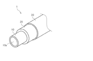
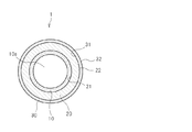
図1は、本構造1の一例についての斜視図であり、図2は、当該本構造1の断面図である。図1及び図2に示すように、本構造1は、内部に流体が流通する配管10と、当該配管10の外周を覆う第一の保温材20と、当該第一の保温材20の外周を覆う第二の保温材30と、を有している。なお、図1においては、説明の便宜のために、配管10の外周を覆う第一の保温材20及び第二の保温材30の一部を省略して、当該配管10、第一の保温材20及び第二の保温材30をそれぞれ露出させて図示している。
FIG. 1 is a perspective view of an example of the
配管10は、本構造1が配置される環境の外気温度より高い温度の液体又は気体を輸送するために設置されている。この配管10は、例えば、炭素鋼やステンレス等の金属製である。配管10の内部に形成された中空部10aには、輸送すべき液体又は気体が流通する。
The
第一の保温材20は、配管10の外気による冷却を抑制するために設けられた断熱材である。第一の保温材20として用いることのできる断熱材は、目的に応じた適切な断熱性を有する部材であれば特に限られないが、例えば、けい酸カルシウム(ゾノライト系けい酸カルシウム等)、パーライト等の断熱性無機多孔質成形体や、グラスウール、ロックウール等の断熱性無機繊維体を好ましく用いることができる。また、第一の保温材20としては、例えば、配管10への施工に先立って、円周方向において複数に分割可能な円筒成形体として形成されたものを用いることもできる。
The first
また、第一の保温材20としては、その撥水性を高める処理が施された断熱性無機多孔質成形体又は無機繊維体を用いることができる。ただし、このような撥水化処理によって第一の保温材20に非透水性を付与することはできず、当該第一の保温材20は透水性を有するものとなる。
Moreover, as the 1st
第二の保温材30は、断熱性、水蒸気透過性及び非透水性を備えている。すなわち、第二の保温材30は、第一の保温材20の内部の温度を上昇させることのできる断熱性を有している。
The 2nd
具体的に、第一の保温材20においては、配管10側の表面(図2に示す、配管10の径方向内側の内面21)の温度に比べて、反対側の表面(図2に示す、配管10の径方向外側の外面22)の温度は低くなる。この点、第一の保温材20の外周(すなわち外面22)を第二の保温材30で覆うことにより、当該第二の保温材30で覆わない場合に比べて、当該第一の保温材20の外面22の温度を上昇させることができる。この結果、第一の保温材20において、外面22付近の温度と内面21付近の温度との差が低減されて、当該第一の保温材20の内部の全域において温度を上昇させることができる。
Specifically, in the first
また、第二の保温材30は、第一の保温材20で発生した水蒸気(すなわち、気体状態の水)が透過することのできる水蒸気透過性も有している。さらに、第二の保温材30は、強い雨や風に晒された場合であっても液体状の水が透過することのできない非透水性をも有している。
The second
第二の保温材30としては、水蒸気透過性と非透水性とを兼ね備えた断熱材を用いることができ、例えば、エアロゲルが充填された繊維体(以下、「エアロゲル繊維体」という。)を好ましく用いることができる。
As the second
このエアロゲル繊維体は、繊維基材にエアロゲルを充填することにより製造することのできる断熱性の構造体である。具体的に、エアロゲル繊維体は、例えば、繊維基材の繊維管にエアロゲルの原料を含浸し、次いで、当該エアロゲルの原料が含浸された繊維基材を超臨界乾燥することにより製造することができる。 This airgel fiber body is a heat insulating structure that can be manufactured by filling a fiber substrate with airgel. Specifically, the airgel fiber body can be produced, for example, by impregnating a fiber tube of a fiber base material with an airgel raw material and then supercritically drying the fiber base material impregnated with the airgel raw material. .
エアロゲル繊維体を構成する繊維基材としては、無機繊維又は有機繊維の織布又は不織布を用いることができる。繊維基材として、繊維が不規則に絡み合った不織布を用いることにより、繊維間にエアロゲルをより効果的に保持することができる。 As a fiber base material which comprises an airgel fiber body, the woven fabric or nonwoven fabric of an inorganic fiber or an organic fiber can be used. By using a nonwoven fabric in which fibers are entangled irregularly as a fiber base material, the airgel can be more effectively held between the fibers.
また、繊維基材を構成する繊維としては、例えば、ポリエチレンテレフタレート(PET)繊維等の樹脂繊維、炭素繊維、ガラス繊維、アルミナ繊維等のセラミックス繊維を用いることができる。 Moreover, as a fiber which comprises a fiber base material, ceramic fibers, such as resin fibers, such as a polyethylene terephthalate (PET) fiber, carbon fiber, glass fiber, an alumina fiber, can be used, for example.
繊維基材に充填されるエアロゲルとしては、無機材料からなるエアロゲル(無機エアロゲル)又は有機材料からなるエアロゲル(有機エアロゲル)を用いることができる。無機エアロゲルを用いることにより、エアロゲル繊維体の耐熱性を効果的に高めることができる。 As an airgel with which a fiber base material is filled, an airgel (inorganic airgel) made of an inorganic material or an airgel (organic airgel) made of an organic material can be used. By using the inorganic airgel, the heat resistance of the airgel fiber can be effectively increased.
無機エアロゲルとしては、例えば、シリカエアロゲルやアルミナエアロゲルを用いることができる。中でも、シリカエアロゲルを用いることにより、エアロゲル繊維体の断熱性を効果的に高めることができる。 As the inorganic airgel, for example, silica airgel or alumina airgel can be used. Especially, the heat insulation of an airgel fiber body can be effectively improved by using a silica airgel.
また、第二の保温材30としては、第一の保温材20よりも断熱性が高いものを好ましく用いることができる。すなわち、例えば、その熱伝導率が、第一の保温材20の熱伝導率よりも低い第二の保温材30を好ましく用いることができる。
Moreover, as the second
具体的に、ASTM C177に準拠した方法で測定される第二の保温材30の25℃における熱伝導率は、例えば、0.05W/(m・K)以下であることが好ましく、0.02W/(m・K)以下であることがより好ましい。
Specifically, the thermal conductivity at 25 ° C. of the second
すなわち、例えば、その熱伝導率が上記の範囲であるエアロゲル繊維体を第二の保温材30として好ましく用いることができる。なお、エアロゲル繊維体の繊維間の空隙を埋めるエアロゲルは、当該エアロゲル内の微細孔により、当該エアロゲル繊維体の内部における空気の対流を効果的に防止することができる。このため、エアロゲル繊維体は、優れた断熱性を有することができる。
That is, for example, an airgel fiber body whose thermal conductivity is in the above range can be preferably used as the second
また、ASTM E96(Procedure B)に準拠した方法で測定される第二の保温材30の水蒸気透過性は、例えば、600ng/(Pa・S・m2)以上であることが好ましく、1500ng/(Pa・S・m2)以上であることがより好ましい。
In addition, the water vapor permeability of the second
また、ASTM C1104に準拠した方法で測定される第二の保温材30の水中浸漬後の吸水率は、例えば、10重量%以下であることが好ましく、4重量%以下であることがより好ましい。また、ASTM C1511に準拠した方法で測定される第二の保温材30の撥水性は、例えば、5g重量減以下であることが好ましく、3g重量減以下であることがより好ましい。
Moreover, the water absorption rate after immersion in water of the second
すなわち、第二の保温材30としては、例えば、上記の範囲の水蒸気透過性に加えて、上記の範囲の吸水率又は撥水性の両方または一方をさらに備えたエアロゲル繊維体を好ましく用いることができる。なお、エアロゲル繊維体は、上述したようなエアロゲル内の微細孔により、優れた断熱性に加えて、上記のような水蒸気透過性と非透水性とを兼ね備えることができる。
That is, as the second
また、第二の保温材30としてエアロゲル繊維体を用いる場合、当該エアロゲル繊維体の嵩密度は、例えば、100〜300kg/m3の範囲とすることが好ましく、150〜200kg/m3の範囲とすることがより好ましい。嵩密度が上記の範囲であるエアロゲル繊維体を用いることで、本構造1の軽量化を図ることができる。
Moreover, when using an airgel fiber body as the 2nd
また、第二の保温材30は、適度な可撓性を有することが好ましい。すなわち、第二の保温材30としては、第一の保温材20の外周に沿って巻き付けることのできる柔軟性を備えたシート状体を用いることができる。
Moreover, it is preferable that the 2nd
具体的に、例えば、不織布である繊維基材にエアロゲルが充填されてなるエアロゲル繊維体のシートを好ましく用いることができる。この場合、エアロゲル繊維体の厚さは、例えば、2〜20mmの範囲であることが好ましく、3〜10mmの範囲であることがより好ましい。 Specifically, for example, an airgel fiber sheet obtained by filling a fiber base material, which is a nonwoven fabric, with airgel can be preferably used. In this case, the thickness of the airgel fiber body is, for example, preferably in the range of 2 to 20 mm, and more preferably in the range of 3 to 10 mm.
本構造1においては、その断熱性を効果的に維持することができる。すなわち、例えば、第一の保温材20が上述したような断熱性無機多孔質成形体や無機繊維体である場合、本構造1の外部から当該第一の保温材20に水が浸入すると、当該第一の保温材20が水を保持してしまい、その結果、当該第一の保温材20の断熱性が低下することとなる。
In the
これに対し、本構造1においては、最外層を構成する第二の保温材30が非透水性を有しているため、例えば、本構造1が雨や雪に晒された場合においても、本構造1の内部に水が浸入して第一の保温材20に水が含まれることを効果的に防止することができる。
On the other hand, in the
したがって、第二の保温材30で第一の保温材20を被覆することによって、当該第一の保温材20の断熱性を効果的に維持することができる。もちろん、第二の保温材20は、それ自身が非透水性であるため、その断熱性を効果的に維持することができる。
Therefore, by covering the first
また、本構造1においては、第一の保温材20の断熱性が低下した場合であっても、その断熱性を効果的に回復させることができる。すなわち、例えば、第一の保温材20の外周に、シート状の第二の保温材30を巻き付けることにより本構造1を製造した場合には、当該第二の保温材30の一部に継ぎ目(不図示)が形成されることとなる。
Moreover, in this
この場合、本構造1に対して雨や雪が強く吹き付けられることにより、第二の保温材30の継ぎ目の隙間から、当該第二の保温材30と第一の保温材20との間に水が浸入し、当該第一の保温材20が水を含むこととなる場合がある。
In this case, when rain or snow is strongly blown against the
しかしながら、本構造1においては、第一の保温材20から水を効果的に排出させることができる。すなわち、上述のとおり、本構造1においては、第一の保温材20は第二の保温材30によって覆われているため、当該第一の保温材20の内部の温度は、内面21から外面22までの全範囲において、配管10の温度に近い範囲で維持することができる。したがって、第一の保温材20に水が浸入した場合には、この水を当該第一の保温材20の内部で効果的に蒸発させることができる。
However, in this
そして、第一の保温材20を覆う第二の保温材30は、気化した水が透過できる水蒸気透過性を有しているため、第一の保温材20に含まれていた水の蒸発により発生した水蒸気は、当該第二の保温材30を透過して、本構造1の外部に効果的に排出される。すなわち、第一の保温材20の内部で発生した水蒸気は、第二の保温材30の当該第一の保温材20側の表面(図2に示す内面31)から、当該第二の保温材30の外気中に露出した表面(図2に示す外面32)まで、当該第二の保温材30の内部を通過して、当該外気中に排出される。
And since the 2nd
このように、本構造1においては、断熱性、水蒸気透過性及び非透水性を備えた第二の保温材30により第一の保温材20が覆われているため、当該第一の保温材20に浸入した水を蒸発させるとともに、当該第二の保温材30を介して排出し、当該第一の保温材20を再び乾燥させることができる。すなわち、本構造1は、断熱性の自己回復能力を備えている。
Thus, in this
また、本構造1においては、第二の保温材30の外周をさらに金属製の外装材で覆うこととしてもよい。図3は、この場合の本構造1の一例についての斜視図であり、図4は、当該本構造1の断面図である。
Moreover, in this
図3及び図4に示す例において、本構造1は、配管10、第一の保温材20、及び第二の保温材30に加えて、さらに当該第二の保温材30の外周を覆う金属製の外装材40を有している。
In the example shown in FIGS. 3 and 4, the
したがって、この本構造1においては、第二の保温材30と外装材40とによって第一の保温材20を被覆するため、外部から当該第一の保温材20に水が浸入することをより効果的に防止することができる。
Therefore, in this
また、本構造1は、最外層として金属製の外装材40を有することによって、その力学的強度を向上させることができる。このため、例えば、作業者が本構造1の上(すなわち、外装材40の上)に乗って所定の作業を行うこともできる。
Moreover, this
次に、具体的な実施例について説明する。 Next, specific examples will be described.
[実施例]
この実施例においては、図3及び図4に示す本構造1における断熱性の自己回復能力を確認した。すなわち、被保温体として、温水を輸送するための配管10を準備した。この配管10は、外径が約200mmである炭素鋼製の円筒状構造体であり、略水平に延びるよう屋外に設置されていた。
[Example]
In this example, the heat-insulating self-healing ability in the
また、第一の保温材20として、けい酸カルシウムを主成分とする円筒状の断熱性無機多孔質成形体を準備した。この新設保温材は、厚さが40mmであり、円周方向において4つに分割可能であった。
Moreover, the cylindrical heat-insulating inorganic porous molded object which has calcium silicate as a main component as the 1st
また、第二の保温材30として、炭素繊維とガラス繊維とを含む混合繊維の不織布である繊維基材に、シリカ系エアロゲルを充填したエアロゲル繊維体(Pyrogel 6350、Aspen Aerogels Inc.)を用いた。このエアロゲル繊維体は、厚さが6mmであって適度な可撓性を有するシート状成形体であった。また、外装材40として、厚さが0.4mmである着色亜鉛メッキ鋼板製の円筒状カバー材を準備した。
Further, as the second
第一の条件においては、まず、樹脂製の袋内において、4つに分割された第一の保温材20の各部分を水中に一昼夜浸漬した。次いで、浸漬により水を含んだ第一の保温材20を容器から取り出し、当該第一の保温材20を配管10の外周を覆うように取り付けた。
In the first condition, first, each part of the first
そして、この水を含んだ第一の保温材20の外周を覆うように第二の保温材30を取り付け、図1及び図2に示すような本構造1を製造した。さらに、第二の保温材30の外周を覆うように、外装材40を取り付けて、図3及び図4に示すような本構造1を製造した。
And the 2nd
こうして、配管10と、浸漬処理によって水を含ませた第一の保温材20と、エアロゲル繊維体からなる第二の保温材30と、金属製の外装材40と、を有する配管構造(構造1)を製造した。
Thus, a piping structure (structure 1) having the piping 10, the first
第二の条件においては、上述の第一の条件と同様に、第一の保温材20を水中に浸漬し、水を含んだ当該第一の保温材20を配管10に取り付けた。そして、第二の保温材30を取り付けることなく、第一の保温材20の外周を外装材40で覆った。こうして、配管10と、浸漬処理によって水を含ませた第一の保温材20と、金属製の外装材40と、を有する配管構造(構造2)を製造した。
In the second condition, similar to the first condition described above, the first
第三の条件においては、水中に浸漬していない乾燥した第一の保温材20を配管10の外周を覆うように取り付けた。そして、この第一の保温材20の外周を覆うように外装材40を取り付けた。こうして、配管10と、乾燥した第一の保温材20と、金属製の外装材40と、を有する配管構造(構造3)を製造した。
Under the third condition, the dried first
このようにして3種類の構造1〜3を屋外において製造した。そして、各構造1〜3の配管10内に温度が61.5℃〜65.8℃の範囲である水を流通させた。さらに、温水の輸送に使用されている各構造1〜3について、最外層である外装材40の外表面の温度と、当該外装材40に覆われた第一の保温材20に含まれる水分の量と、の経時的な変化を測定した。
In this way, three types of
すなわち、構造1〜3を構築してから12日が経過した時点、及び45日が経過した時点のそれぞれのタイミングで表面温度及び水分量を測定した。また、表面温度及び水分量は、水平方向に延びる構造1〜3のうち、鉛直方向における外装材40の上方側表面及び下方側表面のそれぞれに計測器を接触させて測定した。なお、水分の量は、中性子水分計(MCM−2型、CPN社製)により測定した。
That is, the surface temperature and the amount of water were measured at the timing when 12 days had elapsed since the construction of
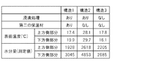
図5には、12日目において測定した結果を示し、図6には、45日目において測定した結果を示す。図5及び図6には、構造1〜3のそれぞれについて、第一の保温材20に水を含ませる浸漬処理を施したか否か、当該第一の保温材20を第二の保温材30で覆ったか否かという条件と、外装材40の上方側部分及び下方側部分のそれぞれで測定された表面温度(℃)、及び外装材40の上方側部分及び下方側部分のそれぞれで測定された水分量(測定値)を示している。
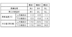
FIG. 5 shows the results measured on the 12th day, and FIG. 6 shows the results measured on the 45th day. In FIG.5 and FIG.6, about each of the structures 1-3, whether the 1st
なお、図5及び図6に示す水分量は、中性子水分計で測定された数値である。第一の保温材20に含まれている水分の量が増加するほど、中性子水分計による測定値も増加する。また、12日目の測定時における気温は13℃、湿度は42%であり、45日目の測定時における気温は10℃、湿度は66%であった。
In addition, the moisture content shown in FIG.5 and FIG.6 is the numerical value measured with the neutron moisture meter. As the amount of moisture contained in the first
図5に示すように、12日目の時点では、構造1〜3のいずれにおいても、上方側の表面温度が下方側部分より高く、また、上方側の水分量も下方側より高かった。これは、構造1〜3のいずれにおいても、保温材に含まれる水分が重力の作用によって下方側に溜まっているためと考えられた。
As shown in FIG. 5, at the time of the twelfth day, in any of the
また、浸漬処理により水を含んだ第一の保温材20を第二の保温材30で被覆することにより製造した構造1の表面温度は、水を含んだ第一の保温材20を第二の保温材30で被覆することなく構築した構造2のそれに比べて低く、また、浸漬処理が施されていない第一の保温材20を有する構造3のそれと同程度であった。
Further, the surface temperature of the
このように、第一の保温材20が第二の保温材30で覆われている構造1の断熱性は、第一の保温材20が第二の保温材30で覆われていない構造2のそれに比べて高くなっていることが確認された。
As described above, the heat insulating property of the
また、構造1の水分量は、構造2に比べて顕著に低かった。すなわち、第一の保温材20が第二の保温材30で覆われている構造1においては、第一の保温材20が第二の保温材30で覆われていない構造2に比べて、水分の排出(すなわち乾燥)がより進行していることが確認された。
In addition, the water content of
さらに、図6に示すように、45日目において、第二の保温材30を有する構造1の表面温度は、第一の保温材20に浸漬処理を施していない構造3のそれと同程度となっていた。また、構造1においては、上面側の表面温度と下面側の表面温度とがほぼ一致していた。さらに、構造1の水分量は、構造3のそれにほぼ一致した。
Furthermore, as shown in FIG. 6, on the 45th day, the surface temperature of the
これに対し、第二の保温材30を有しない構造2の表面温度は、第一の保温材20に浸漬処理を施していない構造3のそれより高かった。また、構造2においては、上面側の表面温度より下面側の表面温度が高かった。さらに、構造2の水分量は、構造3のそれより高かった。
On the other hand, the surface temperature of the structure 2 without the second
このように、第一の保温材20を第二の保温材30で被覆することにより製造された構造1においては、当該第一の保温材20から水分を略完全に排出することができ、その結果、当該第一の保温材20の断熱性を略完全に回復させることができた。
Thus, in the
なお、本発明は、本実施形態に限られるものではない。すなわち、本発明に係る保温構造は、上述したような配管構造に限られない。例えば、保温材で覆われた、横型又は縦型の既設の機器の胴体部や鏡部もまた、本方法による補修の対象となり得る。 Note that the present invention is not limited to this embodiment. That is, the heat retaining structure according to the present invention is not limited to the piping structure as described above. For example, a body part and a mirror part of existing horizontal or vertical equipment covered with a heat insulating material can also be repaired by this method.
1 保温構造、10 配管、10a 中空部、20 第一の保温材、21 第一の保温材の内面、22 第一の保温材の外面、30 第二の保温材、31 第二の保温材の内面、32 第二の保温材の外面、40 外装材。
DESCRIPTION OF
Claims (3)
前記被保温体を覆う第一の保温材と、
前記第一の保温材を覆う、水蒸気透過性と非透水性とを兼ね備えた第二の保温材と、
を有する
ことを特徴とする保温構造。 A body to be insulated,
A first heat insulating material covering the heat insulating body;
A second heat insulating material that covers the first heat insulating material and has both water vapor permeability and non-water permeability;
A heat insulating structure characterized by having.
前記第一の保温材は、前記配管の外周を覆い、
前記第二の保温材は、前記第一の保温材の外周を覆う
ことを特徴とする請求項1に記載された保温構造。 The insulated body is a pipe through which a fluid flows,
The first heat insulating material covers the outer periphery of the pipe,
The heat insulating structure according to claim 1, wherein the second heat insulating material covers an outer periphery of the first heat insulating material.
ことを特徴とする請求項1又は2に記載された保温構造。 The heat insulating structure according to claim 1 or 2, wherein the second heat insulating material is a fibrous body filled with airgel.
Priority Applications (1)
| Application Number | Priority Date | Filing Date | Title |
|---|---|---|---|
| JP2008162611A JP4997187B2 (en) | 2008-06-20 | 2008-06-20 | Thermal insulation structure |
Applications Claiming Priority (1)
| Application Number | Priority Date | Filing Date | Title |
|---|---|---|---|
| JP2008162611A JP4997187B2 (en) | 2008-06-20 | 2008-06-20 | Thermal insulation structure |
Related Child Applications (1)
| Application Number | Title | Priority Date | Filing Date |
|---|---|---|---|
| JP2012047101A Division JP4997353B2 (en) | 2012-03-02 | 2012-03-02 | Thermal insulation structure |
Publications (2)
| Publication Number | Publication Date |
|---|---|
| JP2010002016A true JP2010002016A (en) | 2010-01-07 |
| JP4997187B2 JP4997187B2 (en) | 2012-08-08 |
Family
ID=41583891
Family Applications (1)
| Application Number | Title | Priority Date | Filing Date |
|---|---|---|---|
| JP2008162611A Active JP4997187B2 (en) | 2008-06-20 | 2008-06-20 | Thermal insulation structure |
Country Status (1)
| Country | Link |
|---|---|
| JP (1) | JP4997187B2 (en) |
Cited By (3)
| Publication number | Priority date | Publication date | Assignee | Title |
|---|---|---|---|---|
| JP2012063007A (en) * | 2010-08-18 | 2012-03-29 | Imae Kogyo Kk | Cylindrical heat insulating material and thermal device using the same |
| JP2012127495A (en) * | 2010-11-25 | 2012-07-05 | Nichias Corp | Heat insulating structure |
| CN105020496A (en) * | 2015-07-07 | 2015-11-04 | 陕西延长石油压裂材料有限公司 | Hot coal gas pipeline inner heat preservation method |
Citations (10)
| Publication number | Priority date | Publication date | Assignee | Title |
|---|---|---|---|---|
| JPS60237295A (en) * | 1984-05-09 | 1985-11-26 | 株式会社 美庵 | Heat-insulating execution method of piping member |
| JPS61233293A (en) * | 1985-04-03 | 1986-10-17 | 牧瀬 慎一 | Seamless heat-insulating execution method of piping and sheathing material used for said method |
| JPS62188692U (en) * | 1986-05-20 | 1987-12-01 | ||
| JP2001336692A (en) * | 2000-05-29 | 2001-12-07 | Cd Technos Kk | Heat insulating structure |
| JP2002181280A (en) * | 2000-12-19 | 2002-06-26 | Meisei Ind Co Ltd | Moisture removing method for heat insulating material |
| JP2002321910A (en) * | 2001-04-24 | 2002-11-08 | Matsushita Electric Works Ltd | Method for forming aerogel membrane |
| JP2004340420A (en) * | 2003-05-13 | 2004-12-02 | Toshiba Corp | Refrigerator |
| JP2007508511A (en) * | 2003-10-17 | 2007-04-05 | サン−ゴバン・イソベール | Thermal insulation system for industrial equipment |
| JP2007510794A (en) * | 2003-11-10 | 2007-04-26 | ゴア エンタープライズ ホールディングス,インコーポレイティド | Airgel / PTFE composite insulation material |
| JP2008505261A (en) * | 2004-06-29 | 2008-02-21 | アスペン エアロジェルス,インク. | Energy-efficient building insulation with insulating properties |
-
2008
- 2008-06-20 JP JP2008162611A patent/JP4997187B2/en active Active
Patent Citations (10)
| Publication number | Priority date | Publication date | Assignee | Title |
|---|---|---|---|---|
| JPS60237295A (en) * | 1984-05-09 | 1985-11-26 | 株式会社 美庵 | Heat-insulating execution method of piping member |
| JPS61233293A (en) * | 1985-04-03 | 1986-10-17 | 牧瀬 慎一 | Seamless heat-insulating execution method of piping and sheathing material used for said method |
| JPS62188692U (en) * | 1986-05-20 | 1987-12-01 | ||
| JP2001336692A (en) * | 2000-05-29 | 2001-12-07 | Cd Technos Kk | Heat insulating structure |
| JP2002181280A (en) * | 2000-12-19 | 2002-06-26 | Meisei Ind Co Ltd | Moisture removing method for heat insulating material |
| JP2002321910A (en) * | 2001-04-24 | 2002-11-08 | Matsushita Electric Works Ltd | Method for forming aerogel membrane |
| JP2004340420A (en) * | 2003-05-13 | 2004-12-02 | Toshiba Corp | Refrigerator |
| JP2007508511A (en) * | 2003-10-17 | 2007-04-05 | サン−ゴバン・イソベール | Thermal insulation system for industrial equipment |
| JP2007510794A (en) * | 2003-11-10 | 2007-04-26 | ゴア エンタープライズ ホールディングス,インコーポレイティド | Airgel / PTFE composite insulation material |
| JP2008505261A (en) * | 2004-06-29 | 2008-02-21 | アスペン エアロジェルス,インク. | Energy-efficient building insulation with insulating properties |
Cited By (4)
| Publication number | Priority date | Publication date | Assignee | Title |
|---|---|---|---|---|
| JP2012063007A (en) * | 2010-08-18 | 2012-03-29 | Imae Kogyo Kk | Cylindrical heat insulating material and thermal device using the same |
| JP2012127495A (en) * | 2010-11-25 | 2012-07-05 | Nichias Corp | Heat insulating structure |
| CN105020496A (en) * | 2015-07-07 | 2015-11-04 | 陕西延长石油压裂材料有限公司 | Hot coal gas pipeline inner heat preservation method |
| CN105020496B (en) * | 2015-07-07 | 2017-11-17 | 陕西延长石油压裂材料有限公司 | A kind of method of heating gas pipeline inside holding |
Also Published As
| Publication number | Publication date |
|---|---|
| JP4997187B2 (en) | 2012-08-08 |
Similar Documents
| Publication | Publication Date | Title |
|---|---|---|
| JP4897858B2 (en) | Thermal insulation repair method and thermal insulation structure | |
| JP2009243518A5 (en) | Flexible tube for cryogenic fluid transport | |
| CN202914905U (en) | Steam conveying pipeline with three-layer heat preservation structure adopted | |
| JP4997187B2 (en) | Thermal insulation structure | |
| JP5905861B2 (en) | Endothermic material using inorganic porous material | |
| JP4997186B2 (en) | Thermal insulation structure and repair method | |
| CN106195464B (en) | A kind of bamboo winding composite pressure pipe | |
| JP4997353B2 (en) | Thermal insulation structure | |
| PL181809B1 (en) | Insulation and method of placing it onto a pipe or container | |
| JP6618879B2 (en) | Thermal insulation structure and method for attaching the thermal insulation structure to piping | |
| JP2011127624A (en) | Low-temperature tank and method of manufacturing the same | |
| KR101949228B1 (en) | Heat insulating materials for ducts | |
| US11680672B2 (en) | Insulation blanket having a deposited passivator for industrial insulation applications | |
| CN205955362U (en) | Constant temperature tent | |
| CN206299946U (en) | Superhigh temperature prefabricated direct-buried thermal insulation pipe | |
| JP5613490B2 (en) | Refractory double-layer pipe and method for producing the same | |
| RU185206U1 (en) | Tank container | |
| JP5972556B2 (en) | Thermal insulation structure | |
| CN103291019A (en) | Heat preserving, damp proofing and vapor permeating method for metal roof | |
| BR112018069418B1 (en) | DEVICE OPERATING AT HIGH TEMPERATURE COMPRISING AN INSULATING PRODUCT, INSULATING PRODUCT ADAPTED TO SUCH A DEVICE, USE AND PROCESS FOR OBTAINING SUCH INSULATING PRODUCT | |
| Ananthan et al. | Silica aerogels for energy conservation and saving | |
| CN202324231U (en) | External heat-preserving structure of wall body | |
| Bhatia | Overview of Insulation Materials | |
| CN217711191U (en) | Aerogel heat insulation board | |
| CN104879612B (en) | A kind of compound insulating material and heat preserving method |
Legal Events
| Date | Code | Title | Description |
|---|---|---|---|
| A621 | Written request for application examination |
Free format text: JAPANESE INTERMEDIATE CODE: A621 Effective date: 20101109 |
|
| A871 | Explanation of circumstances concerning accelerated examination |
Free format text: JAPANESE INTERMEDIATE CODE: A871 Effective date: 20110908 |
|
| A975 | Report on accelerated examination |
Free format text: JAPANESE INTERMEDIATE CODE: A971005 Effective date: 20110926 |
|
| A977 | Report on retrieval |
Free format text: JAPANESE INTERMEDIATE CODE: A971007 Effective date: 20111226 |
|
| A131 | Notification of reasons for refusal |
Free format text: JAPANESE INTERMEDIATE CODE: A131 Effective date: 20120110 |
|
| A521 | Request for written amendment filed |
Free format text: JAPANESE INTERMEDIATE CODE: A523 Effective date: 20120302 |
|
| TRDD | Decision of grant or rejection written | ||
| A01 | Written decision to grant a patent or to grant a registration (utility model) |
Free format text: JAPANESE INTERMEDIATE CODE: A01 Effective date: 20120424 |
|
| A01 | Written decision to grant a patent or to grant a registration (utility model) |
Free format text: JAPANESE INTERMEDIATE CODE: A01 |
|
| A61 | First payment of annual fees (during grant procedure) |
Free format text: JAPANESE INTERMEDIATE CODE: A61 Effective date: 20120514 |
|
| FPAY | Renewal fee payment (event date is renewal date of database) |
Free format text: PAYMENT UNTIL: 20150518 Year of fee payment: 3 |
|
| R150 | Certificate of patent or registration of utility model |
Free format text: JAPANESE INTERMEDIATE CODE: R150 Ref document number: 4997187 Country of ref document: JP Free format text: JAPANESE INTERMEDIATE CODE: R150 |
|
| FPAY | Renewal fee payment (event date is renewal date of database) |
Free format text: PAYMENT UNTIL: 20150518 Year of fee payment: 3 |
|
| S531 | Written request for registration of change of domicile |
Free format text: JAPANESE INTERMEDIATE CODE: R313531 |
|
| R350 | Written notification of registration of transfer |
Free format text: JAPANESE INTERMEDIATE CODE: R350 |
|
| R250 | Receipt of annual fees |
Free format text: JAPANESE INTERMEDIATE CODE: R250 |
|
| S111 | Request for change of ownership or part of ownership |
Free format text: JAPANESE INTERMEDIATE CODE: R313114 |
|
| R350 | Written notification of registration of transfer |
Free format text: JAPANESE INTERMEDIATE CODE: R350 |
|
| R250 | Receipt of annual fees |
Free format text: JAPANESE INTERMEDIATE CODE: R250 |
|
| R250 | Receipt of annual fees |
Free format text: JAPANESE INTERMEDIATE CODE: R250 |
|
| R250 | Receipt of annual fees |
Free format text: JAPANESE INTERMEDIATE CODE: R250 |
|
| R250 | Receipt of annual fees |
Free format text: JAPANESE INTERMEDIATE CODE: R250 |
|
| R250 | Receipt of annual fees |
Free format text: JAPANESE INTERMEDIATE CODE: R250 |
|
| R250 | Receipt of annual fees |
Free format text: JAPANESE INTERMEDIATE CODE: R250 |
|
| R250 | Receipt of annual fees |
Free format text: JAPANESE INTERMEDIATE CODE: R250 |
|
| R250 | Receipt of annual fees |
Free format text: JAPANESE INTERMEDIATE CODE: R250 |
|
| R250 | Receipt of annual fees |
Free format text: JAPANESE INTERMEDIATE CODE: R250 |