JP2010001109A - Sheet treatment device and image forming device - Google Patents

Sheet treatment device and image forming device Download PDF

Info

Publication number
JP2010001109A
JP2010001109A JP2008159784A JP2008159784A JP2010001109A JP 2010001109 A JP2010001109 A JP 2010001109A JP 2008159784 A JP2008159784 A JP 2008159784A JP 2008159784 A JP2008159784 A JP 2008159784A JP 2010001109 A JP2010001109 A JP 2010001109A
Authority
JP
Japan
Prior art keywords
sheet
folded
processing apparatus
folding
pressing
Prior art date
Legal status (The legal status is an assumption and is not a legal conclusion. Google has not performed a legal analysis and makes no representation as to the accuracy of the status listed.)
Granted
Application number
JP2008159784A
Other languages
Japanese (ja)
Other versions
JP5219642B2 (en
Inventor
Takashi Yokoya
貴司 横谷
Current Assignee (The listed assignees may be inaccurate. Google has not performed a legal analysis and makes no representation or warranty as to the accuracy of the list.)
Canon Inc
Original Assignee
Canon Inc
Priority date (The priority date is an assumption and is not a legal conclusion. Google has not performed a legal analysis and makes no representation as to the accuracy of the date listed.)
Filing date
Publication date
Application filed by Canon Inc filed Critical Canon Inc
Priority to JP2008159784A priority Critical patent/JP5219642B2/en
Publication of JP2010001109A publication Critical patent/JP2010001109A/en
Application granted granted Critical
Publication of JP5219642B2 publication Critical patent/JP5219642B2/en
Expired - Fee Related legal-status Critical Current
Anticipated expiration legal-status Critical

Links

Images

Abstract

<P>PROBLEM TO BE SOLVED: To prevent reduction of alignment property of a bundle of sheets by preventing loading failure, and to prevent reduction of dignity of a binding product. <P>SOLUTION: Sheet pressing members 590a, 590b can be moved to a pressing position for pressing the bundle of sheets stacked on a sheet stacking part 530 and a retreating position spaced from the bundle of sheets and retreated in a direction crossing to a sheet conveying direction. Further, before the sheet is conveyed to the sheet stacking part 530 by crossing movement parts 600a, 600b, the sheet pressing members 590a, 590b are moved to the pressing position to press the bundle of sheets stacked on the sheet stacking part 530. Subsequently, after the sheet is conveyed to the sheet stacking part 530, the sheet pressing members 590a, 590b are moved to a retreating position. <P>COPYRIGHT: (C)2010,JPO&INPIT

Description

本発明は、シート積載部にシートを搬送してシート束を形成するシート処理装置及びこのシート処理装置を備えた画像形成装置に関する。   The present invention relates to a sheet processing apparatus that conveys a sheet to a sheet stacking unit to form a sheet bundle, and an image forming apparatus including the sheet processing apparatus.

従来、画像形成されたシートを順次取り込み、シート束を形成してシート束の略中央付近に綴じ処理、折り処理を施し、冊子を形成する中綴じ製本処理を行うシート処理装置を備えた画像形成装置が知られている(特許文献1参照)。綴じ位置で折り曲げられて中綴じ製本処理が施されたシート束は、機外に配置されるシート積載トレイに製本成果物が排出される。   2. Description of the Related Art Conventionally, an image forming apparatus having a sheet processing apparatus that sequentially captures image-formed sheets, forms a sheet bundle, performs a binding process and a folding process near the center of the sheet bundle, and performs a saddle stitch bookbinding process to form a booklet. An apparatus is known (see Patent Document 1). For the sheet bundle that has been folded at the binding position and subjected to the saddle stitch binding process, the bookbinding product is discharged to a sheet stacking tray disposed outside the apparatus.

また、シートに対して所定の折り処理を行い、折りシートを形成するシート折り処理手段を有するシート処理装置を備えた画像形成装置が知られている(特許文献2参照)。   An image forming apparatus including a sheet processing apparatus having a sheet folding processing unit that performs a predetermined folding process on a sheet to form a folded sheet is known (see Patent Document 2).

近年、予めシート折り処理手段にて2つ折りされたシートを、中紙として使用して中綴じ製本処理する画像形成装置が提案されている。製本成果物の中紙に折りシートを使用することで、例えば見開きのページなどを作成することができ、製本物の付加価値を向上させることが可能となる。   In recent years, there has been proposed an image forming apparatus that performs saddle stitching using a sheet folded in advance by a sheet folding processing unit as a saddle sheet. By using a folded sheet for the middle paper of the bookbinding product, for example, a spread page can be created, and the added value of the bookbinding product can be improved.

特開2007−62959号公報JP 2007-62959 A 特開2001−26353号公報JP 2001-26353 A

しかしながら、上述したシート処理装置において、シート搬送方向と直交する方向の折り目を有する折りシートを製本成果物の中紙とする場合には、既積載の折りシートの折り開口側に搬送されてきた次のシートが入り込んでしまうおそれがあった。具体例を挙げて説明すると、図28〜図30は、従来のシート処理装置におけるシート積載部近傍を示す説明図である。シート処理装置は、図28に示すように、略垂直に傾斜して配置された製本処理トレイ(積載部本体)560と、製本処理トレイ560の下端に配置されるシート位置決め部材(シート束受け部)554とを有するシート積載部530を備えている。そして、シート積載部530にシートPが順次搬送されてきて積重ねられ、シート束が形成されるようになっている。   However, in the above-described sheet processing apparatus, when a folded sheet having a fold line in a direction orthogonal to the sheet conveying direction is used as the middle sheet of the bookbinding product, the next sheet that has been conveyed to the folding opening side of the already loaded folded sheets. There was a risk that the sheet of rushed in. A specific example will be described. FIGS. 28 to 30 are explanatory views showing the vicinity of a sheet stacking unit in a conventional sheet processing apparatus. As shown in FIG. 28, the sheet processing apparatus includes a bookbinding processing tray (stacking unit main body) 560 that is inclined substantially vertically, and a sheet positioning member (sheet bundle receiving unit) that is disposed at the lower end of the bookbinding processing tray 560. 554). The sheets P are sequentially conveyed and stacked on the sheet stacking unit 530 to form a sheet bundle.

そして、シート積載部530に積載された折りシートPに続けて、次のシートP’が搬送されてきた場合、折りシートPの折り返し部が図29に示すように開いた状態となっていると、次のシートP’が折りシートPの折り開口側に入り込んでしまうことがあった。   Then, when the next sheet P ′ is conveyed after the folded sheet P stacked on the sheet stacking unit 530, the folded portion of the folded sheet P is in an open state as shown in FIG. In some cases, the next sheet P ′ enters the folding opening side of the folded sheet P.

また、次のシートP’が折りシートPの折り開口側に入り込まなかったとしても、図30に示すように、折りシートPの開きによって次のシートP’との間に隙間が生じてしまうことがある。このようにシート間に隙間が生じてしまうと、その後搬送されてきたシートが隙間に入り込んでしまうことがあった。   Further, even if the next sheet P ′ does not enter the folding opening side of the folded sheet P, as shown in FIG. 30, a gap is generated between the next sheet P ′ due to the opening of the folded sheet P. There is. If a gap is generated between the sheets as described above, the sheet that has been conveyed after that may enter the gap.

また、このようにシート積載部530に積載されているシート束にシート搬送方向と直交する方向の折り目を有する折りシートが含まれていなくても、シートが膨らんでシート間に隙間が生じてしまうことがある。例えば、シート束にシート搬送方向と平行な方向の折り目を有する折りシートが含まれている場合や製本処理トレイ560に積載されているシートがカールしている場合等である。このように製本処理トレイ560においてシート間に隙間が生じてしまうと、製本処理トレイ560に搬送られてきた次のシートが隙間に入り込んでしまうことがあった。   Further, even if the sheet bundle stacked in the sheet stacking unit 530 does not include a folded sheet having a fold in a direction orthogonal to the sheet conveying direction, the sheet swells and a gap is generated between the sheets. Sometimes. For example, the sheet bundle includes a folded sheet having a fold in a direction parallel to the sheet conveying direction, or a sheet stacked on the bookbinding tray 560 is curled. If a gap is generated between sheets in the bookbinding tray 560 as described above, the next sheet conveyed to the bookbinding tray 560 may enter the gap.

そして、搬送されてきたシートが、折りシートの折り開口側に入り込んだり、シート間の隙間に入り込んだりする積載不良が発生すると、シート積載部に積載されたシート束の整合性が損なわれるという問題がある。   Then, when a stacking failure occurs in which the conveyed sheet enters the folding opening side of the folded sheet or enters the gap between the sheets, the consistency of the sheet bundle stacked on the sheet stacking unit is impaired. There is.

そこで、本発明は、上述の事情に鑑みてなされたものであり、積載不良を防止して、シート束の整合性の低下を防止するシート処理装置及び画像形成装置を提供することを目的とするものである。   SUMMARY An advantage of some aspects of the invention is that it provides a sheet processing apparatus and an image forming apparatus that prevent poor stacking and prevent deterioration of sheet bundle alignment. Is.

本発明は、折りシートを含むシート束を処理するシート処理装置において、搬送されたシートを積載するシート積載部と、前記シート積載部に積載されたシートを押える押え位置と、シートから離間する退避位置とに移動可能なシート押え部材と、を備え、前記シート押え部材は、折りシートの折り返し部を押える、ことを特徴とするものである。   The present invention relates to a sheet processing apparatus that processes a bundle of sheets including folded sheets, a sheet stacking unit for stacking conveyed sheets, a pressing position for pressing the sheets stacked on the sheet stacking unit, and a retreat separated from the sheet. A sheet pressing member movable to a position, and the sheet pressing member presses a folded portion of the folded sheet.

また、本発明は、シートに画像を形成する画像形成部と、前記画像形成部により画像形成されたシートを処理する上記シート処理装置と、を備えた、ことを特徴とするものである。   In addition, the present invention includes an image forming unit that forms an image on a sheet, and the sheet processing apparatus that processes the sheet on which an image is formed by the image forming unit.

本発明によれば、シート押え部材によりシート積載部に搬送されたシート束を押えることで、折りシートの開きやシート間の隙間の発生を抑制し、搬送されてきたシートが折りシートの折り開口側やシート間の隙間に入り込む積載不良を防止することができる。これにより、シート束の整合性の低下を防止することができる。   According to the present invention, by pressing the sheet bundle conveyed to the sheet stacking unit by the sheet pressing member, it is possible to suppress the opening of the folded sheet and the generation of a gap between the sheets, and the conveyed sheet is folded to the folded sheet. It is possible to prevent stacking defects that enter the gaps between the sides and the sheets. Thereby, it is possible to prevent a decrease in the consistency of the sheet bundle.

以下、本発明を実施するための最良の形態を図面を参照しながら詳細に説明する。   Hereinafter, the best mode for carrying out the present invention will be described in detail with reference to the drawings.

図1は、本発明の実施の形態に係るシート処理装置を備えた画像形成装置の一例である複写機の断面図である。   FIG. 1 is a sectional view of a copying machine as an example of an image forming apparatus provided with a sheet processing apparatus according to an embodiment of the present invention.

図1において、画像形成装置としての複写機10は、画像形成装置本体としての複写機本体300と、複写機本体300の上面に配されたイメージリーダ200とを備えている。   In FIG. 1, a copying machine 10 as an image forming apparatus includes a copying machine body 300 as an image forming apparatus body and an image reader 200 disposed on the upper surface of the copying machine body 300.

ここで、原稿画像を読み取るイメージリーダ200は、原稿給送装置100、スキャナユニット104、レンズ108、イメージセンサ109等を備えている。そして、このイメージリーダ200により原稿Dを読み取る際には、まずユーザが原稿給送装置100のトレイ100a上に原稿Dをセットする。このとき原稿Dは、トレイ100a上に画像が形成されている面が上向きのフェイスアップ状態でセットされているものとする。   Here, the image reader 200 that reads a document image includes a document feeder 100, a scanner unit 104, a lens 108, an image sensor 109, and the like. When reading the document D with the image reader 200, first, the user sets the document D on the tray 100 a of the document feeder 100. At this time, it is assumed that the document D is set with the face on which the image is formed on the tray 100a facing upward.

次に、このようにセットされた原稿Dを原稿給送装置100により先頭ページから順に1枚ずつ左方向に搬送した後、湾曲したパスを介してプラテンガラス102上を左方向から右方向へ搬送し、この後、排紙トレイ112上に排出する。   Next, the document D set in this way is transported one by one from the first page in order to the left by the document feeder 100, and then transported from the left to the right on the platen glass 102 through a curved path. Thereafter, the paper is discharged onto the paper discharge tray 112.

この際、所謂流し読みによる原稿読み取りの際には、スキャナユニット104は、所定の位置に保持された状態にあり、このスキャナユニット104上を原稿Dが左から右へと通過することにより原稿Dの読取処理が行われる。この読取処理においては、プラテンガラス102上を通過する際、原稿Dに対してスキャナユニット104のランプ103により光を照射し、その反射光をミラー105,106,107、レンズ108を介してイメージセンサ109に導くようにする。なお、このイメージセンサ109により読み取られた原稿の画像データは、所定の画像処理が施されて露光制御部110にビデオ信号として入力される。   At this time, when reading the original by so-called flow reading, the scanner unit 104 is held in a predetermined position, and the original D passes through the scanner unit 104 from left to right. The reading process is performed. In this reading process, when passing through the platen glass 102, the document D is irradiated with light from the lamp 103 of the scanner unit 104, and the reflected light is imaged through the mirrors 105, 106, 107 and the lens 108. Lead to 109. The document image data read by the image sensor 109 is subjected to predetermined image processing and is input to the exposure control unit 110 as a video signal.

一方、所謂固定読みによる原稿読み取りの際には、原稿給送装置100により搬送した原稿Dをプラテンガラス102上に一旦停止させ、この状態でスキャナユニット104を左から右へと移動させることにより原稿の読取処理を行う。さらに、原稿給送装置100を使用しないで原稿の読み取りを行う場合には、ユーザは、原稿給送装置100を持ち上げ、プラテンガラス102上に原稿をセットする。   On the other hand, when reading a document by so-called fixed reading, the document D transported by the document feeder 100 is temporarily stopped on the platen glass 102, and the scanner unit 104 is moved from left to right in this state, thereby moving the document. The reading process is performed. Further, when reading a document without using the document feeder 100, the user lifts the document feeder 100 and sets the document on the platen glass 102.

また、複写機本体300は、カセット114,115に収納されたシートPを給送するシート給送部1002と、シート給送部1002により給送されたシートPに画像を形成する画像形成部1003とを備えている。更に、複写機本体300は、画像形成に関する各種機能を設定する複数のキー、設定状態を示す情報を表示するための表示部等を有する操作表示装置400を備えている。   Further, the copying machine main body 300 includes a sheet feeding unit 1002 that feeds the sheets P stored in the cassettes 114 and 115, and an image forming unit 1003 that forms an image on the sheet P fed by the sheet feeding unit 1002. And. The copying machine main body 300 further includes an operation display device 400 having a plurality of keys for setting various functions relating to image formation, a display unit for displaying information indicating the setting state, and the like.

ここで、画像形成部1003は、感光体ドラム111、現像器113、転写帯電器116等を備えている。そして、画像形成の際には、露光制御部110からのレーザ光が感光体ドラム111上に照射されることにより、感光体ドラム111上に潜像が形成され、さらにこの潜像は、この後、現像器113によってトナー像として顕像化されるようになっている。なお、画像形成部1003の下流側には定着部117、排出ローラ対118等が配設されている。   Here, the image forming unit 1003 includes a photosensitive drum 111, a developing unit 113, a transfer charging unit 116, and the like. When forming an image, a laser beam from the exposure control unit 110 is irradiated onto the photosensitive drum 111, thereby forming a latent image on the photosensitive drum 111. The developer 113 visualizes the toner image. A fixing unit 117, a discharge roller pair 118, and the like are disposed on the downstream side of the image forming unit 1003.

また、シート給送部1002は、各カセット114,115に収納されたシートPを繰り出すピックアップローラ127,128と、フィードローラ及びリタードローラからなる分離ローラ対129,130とを備えている。そして、分離ローラ対129,130によってカセット114,115の最上位のシートPのみが分離搬送される。   The sheet feeding unit 1002 includes pickup rollers 127 and 128 for feeding out the sheets P stored in the respective cassettes 114 and 115, and separation roller pairs 129 and 130 including a feed roller and a retard roller. Then, only the uppermost sheet P of the cassettes 114 and 115 is separated and conveyed by the pair of separation rollers 129 and 130.

次に、このような構成の複写機本体300の画像形成動作ついて説明する。   Next, an image forming operation of the copying machine main body 300 having such a configuration will be described.

まず、既述したようにイメージリーダ200における流し読み、或は固定読み等において、イメージセンサ109により読み取られた原稿Dの画像データは、所定の画像処理が施された後、露光制御部110へ送られる。露光制御部110は、入力したビデオ信号に基づきレーザ光を変調して出力する。   First, as described above, the image data of the document D read by the image sensor 109 in the flow reading or the fixed reading in the image reader 200 is subjected to predetermined image processing, and then to the exposure control unit 110. Sent. The exposure control unit 110 modulates and outputs laser light based on the input video signal.

そして、このレーザ光は、ポリゴンミラー110aにより走査されながら感光体ドラム111上に照射され、感光体ドラム111上には走査されたレーザ光に応じた静電潜像が形成される。次に、感光体ドラム111上に形成された静電潜像を現像器113により現像し、トナー像として可視化する。   The laser beam is irradiated onto the photosensitive drum 111 while being scanned by the polygon mirror 110a, and an electrostatic latent image corresponding to the scanned laser beam is formed on the photosensitive drum 111. Next, the electrostatic latent image formed on the photosensitive drum 111 is developed by the developing unit 113 and visualized as a toner image.

一方、シートPは、カセット114,115、手差し給紙部125、両面搬送パス124の何れかから感光体ドラム111と転写帯電器116とにより構成される転写部へ搬送される。そして、この転写部において可視化された感光体ドラム111上のトナー像がシートPに転写される。この後、シートPは、定着部117にて定着処理が施される。   On the other hand, the sheet P is conveyed from any of the cassettes 114 and 115, the manual sheet feeding unit 125, and the double-sided conveyance path 124 to a transfer unit including the photosensitive drum 111 and the transfer charger 116. Then, the toner image on the photosensitive drum 111 visualized in the transfer portion is transferred to the sheet P. Thereafter, the sheet P is subjected to a fixing process by the fixing unit 117.

次に、定着部117を通過したシートPを切換部材121により一旦パス122に導き、シートPの後端が切換部材121を抜けた後に、シートPをスイッチバックさせ、切換部材121により排出ローラ対118へ搬送し、複写機本体300から排出する。これにより、シートPをトナー像が形成された面が下向きの状態(フェイスダウン)で複写機本体300から排出することができる。   Next, the sheet P that has passed through the fixing unit 117 is once guided to the path 122 by the switching member 121, and after the trailing end of the sheet P has passed through the switching member 121, the sheet P is switched back, and the switching member 121 causes the discharge roller pair It is conveyed to 118 and discharged from the copying machine main body 300. As a result, the sheet P can be discharged from the copying machine main body 300 with the surface on which the toner image is formed facing down (face down).

なお、このような所謂反転排紙により、フェイスダウンでシートPを排出することにより、先頭ページから順に画像形成処理を行う場合、例えば、原稿給送装置100を使用して画像形成処理を行う場合には、ページ順序を揃えることができる。また、コンピュータからの画像データに対する画像形成処理を行う場合にもページ順序を揃えることができる。   In addition, when image forming processing is performed in order from the first page by discharging the sheet P face-down by such so-called reverse paper discharging, for example, when image forming processing is performed using the document feeder 100. The page order can be aligned. Also, the page order can be aligned when image forming processing is performed on image data from a computer.

手差し給紙部125から搬送するOHPシート等の硬いシートPに対して画像形成処理を行う場合は、パス122にシートPを導くことなく、トナー像が形成された面を上向きの状態(フェイスアップ)で排出ローラ対118により複写機本体300から排出する。   When image forming processing is performed on a hard sheet P such as an OHP sheet conveyed from the manual sheet feeding unit 125, the surface on which the toner image is formed is faced up (face up) without guiding the sheet P to the path 122. ), The paper is discharged from the copying machine main body 300 by the discharge roller pair 118.

また、シートPの両面に画像形成処理を行う場合は、シートPを定着部117からまっすぐ排出ローラ方向へと導き、シートPの後端が切換部材121を抜けた直後にシートPをスイッチバックし、切換部材121により両面搬送パス124へと搬送する。両面搬送パス124へ導かれたシートPは、感光体ドラム111と転写帯電器116との間に再度給送される。   When image forming processing is performed on both sides of the sheet P, the sheet P is guided straight from the fixing unit 117 toward the discharge roller, and the sheet P is switched back immediately after the rear end of the sheet P passes through the switching member 121. Then, the sheet is conveyed to the double-sided conveyance path 124 by the switching member 121. The sheet P guided to the duplex conveying path 124 is fed again between the photosensitive drum 111 and the transfer charger 116.

ところで、複写機10は、複写機本体300のシート搬送方向下流側に配設され、複写機本体300の画像形成部1003により画像形成されたシートPを処理するシート処理装置1000を備えている。   Incidentally, the copying machine 10 includes a sheet processing apparatus 1000 that is disposed on the downstream side of the copying machine main body 300 in the sheet conveyance direction and that processes the sheet P on which an image is formed by the image forming unit 1003 of the copying machine main body 300.

シート処理装置1000は、複写機本体300から排出される画像形成済みのシートPを折り処理するシート折り処理手段としてのシート折り装置700と、シートPに対して綴じ処理や製本処理を行うフィニッシャ500と、を備えている。   The sheet processing apparatus 1000 includes a sheet folding apparatus 700 serving as a sheet folding processing unit that performs folding processing on the image-formed sheet P discharged from the copying machine main body 300, and a finisher 500 that performs binding processing and bookbinding processing on the sheet P. And.

複写機本体300の排出ローラ対118により排出されたシートPは、シート折り装置700に送られて選択的に折り処理が行われる。シート折り装置700を通過したシートPは、フィニッシャ500に送られ、フィニッシャ500では綴じ処理や製本処理などの各処理が行われる。   The sheet P discharged by the discharge roller pair 118 of the copying machine main body 300 is sent to the sheet folding device 700 and selectively folded. The sheet P that has passed through the sheet folding apparatus 700 is sent to the finisher 500, and the finisher 500 performs various processes such as a binding process and a bookbinding process.

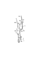
次に、シート折り装置700について詳細に説明する。図2は、シート折り装置700及びフィニッシャ500を有するシート処理装置1000を示す説明図である。また、図3及び図4は、シート折り装置700を示す説明図である。   Next, the sheet folding apparatus 700 will be described in detail. FIG. 2 is an explanatory diagram showing a sheet processing apparatus 1000 having a sheet folding apparatus 700 and a finisher 500. 3 and 4 are explanatory views showing the sheet folding apparatus 700. FIG.

複写機本体300から排出されたシートPは、シート折り装置700の搬送路150又は受入搬送路152へ切換部材151によって選択的に案内される。例えば、A3サイズやB4サイズのシートPで且つ折り処理の指定が操作表示装置400よりなされている場合、複写機本体300より排出されたシートPは、受入搬送路152へ案内され、折り処理が行なわれる。   The sheet P discharged from the copying machine main body 300 is selectively guided to the conveyance path 150 or the reception conveyance path 152 of the sheet folding apparatus 700 by the switching member 151. For example, when an A3 size or B4 size sheet P is specified and the folding display is designated by the operation display device 400, the sheet P discharged from the copying machine main body 300 is guided to the receiving conveyance path 152 and the folding process is performed. Done.

一方、それ以外の場合、複写機本体300から排出されたシートPは、搬送路150に案内され、折り処理を行うことなくそのままフィニッシャ500へと搬送される。このように、シート折り装置700では、シートPを2つに折り畳む2つ折り処理が選択的に行われる。   On the other hand, in other cases, the sheet P discharged from the copying machine main body 300 is guided to the conveyance path 150 and is conveyed to the finisher 500 as it is without being folded. As described above, in the sheet folding apparatus 700, the folding process for folding the sheet P in two is selectively performed.

シート搬送方向と直交する方向に折り目を有する2つ折り処理を実行する場合、シート折り装置700は、シートPを切換部材151によって、図3に示す受入搬送路152に案内し、搬送ローラ対153で搬送し、シート先端受けストッパ154で受け止める。   When performing a two-fold process having a fold in a direction orthogonal to the sheet conveyance direction, the sheet folding apparatus 700 guides the sheet P to the receiving conveyance path 152 shown in FIG. The sheet is conveyed and received by the sheet leading edge receiving stopper 154.

このとき、図示しないモータにより、図3に示すシート先端受けストッパ154を、シートサイズ及びシートPの折り量情報に基づいて+方向(下方向)又は−方向(上方向)に移動して待機させる。これにより、折り目から折りシートPの折り返し部の端部(折り端部)までの長さを調節することが可能となる。シートサイズや、シートPの折りシート情報は、複写機本体300から送られてくる情報である。   At this time, a sheet leading edge stopper 154 shown in FIG. 3 is moved in the + direction (downward) or the − direction (upward) based on the sheet size and the folding amount information of the sheet P by a motor (not shown) and waits. . Thereby, it becomes possible to adjust the length from the fold to the end (folded end) of the folded portion of the folded sheet P. The sheet size and the folded sheet information of the sheet P are information sent from the copying machine main body 300.

ところで、搬送されてきたシートPがシート先端受けストッパ154に勢いよくぶつかり、振動したり、シート先端受けストッパ154上で飛び跳ねて斜めになったりすることがある。そして、そのようなシートPを折り曲げローラ155,156によって折り曲げたとき、シートPの先端に対して平行にシートPを折り曲げることができなくなる。これにより、シートPに皺が生じたり、或は、折られたシートPの側端同士を揃えることができず、一方の側端が他方の側端からはみ出し、その後のシートPの搬送に支障をきたし、ジャムの発生原因になることがある。   By the way, the conveyed sheet P may strike the sheet leading edge receiving stopper 154 vigorously and vibrate, or may jump on the sheet leading edge receiving stopper 154 and be inclined. When such a sheet P is folded by the folding rollers 155 and 156, the sheet P cannot be folded parallel to the leading end of the sheet P. As a result, the sheet P is wrinkled or the side edges of the folded sheet P cannot be aligned with each other, and one side edge protrudes from the other side edge, hindering the subsequent conveyance of the sheet P. May cause jams.

そこで、搬送されてきたシートPがシート先端受けストッパ154上で飛び跳ねないようにするため、シートPの先端がシート先端受けストッパ154よりやや上流側に到達したとき、シート先端検知センサ157によってシートPの先端を検知している。そして、シートPを搬送中に搬送ローラ対153を回転させている搬送モータM21に1回目の停止をさせ、所定時間後に、再始動(1回目の始動)させて、シートPの先端をシート先端受けストッパ154に当接させる。   Accordingly, in order to prevent the conveyed sheet P from jumping on the sheet leading edge receiving stopper 154, when the leading edge of the sheet P reaches slightly upstream from the sheet leading edge receiving stopper 154, the sheet leading edge detection sensor 157 causes the sheet P to be detected. The tip of is detected. Then, the conveyance motor M21 that rotates the conveyance roller pair 153 during the conveyance of the sheet P is stopped for the first time, and restarted after the predetermined time (first activation), and the leading edge of the sheet P is moved to the leading edge of the sheet P. It is brought into contact with the receiving stopper 154.

これによって、シートPは、シート先端受けストッパ154上で飛び跳ねることなく、静かにシート先端受けストッパ154上に着地する。   As a result, the sheet P quietly lands on the sheet leading edge receiving stopper 154 without jumping on the sheet leading edge receiving stopper 154.

その後、搬送ローラ対153は、シートPの先端をシート先端受けストッパ154に当接させたまま、シートPの搬送を継続する。シートPに発生したループ(湾曲)部は、案内壁158の開口部159からはみ出して、座屈状態で、折り曲げローラ155,156のニップ部に接近する。   Thereafter, the conveyance roller pair 153 continues to convey the sheet P while keeping the leading edge of the sheet P in contact with the sheet leading edge receiving stopper 154. The loop (curved) portion generated in the sheet P protrudes from the opening 159 of the guide wall 158 and approaches the nip portion of the folding rollers 155 and 156 in a buckled state.

シートPのループ部が、折り曲げローラ155,156のニップ部に接近したとき、搬送モータM21に2回目の停止をさせ、ループ部の振動が収まってから、2回目の始動をさせる。このため、ループ部は、安定した状態でニップ部に送り込まれる。搬送モータM21の2回目の停止のタイミングは、シートPの先端がシート先端受けストッパ154に当接する前に、シート先端検知センサ157によってシート先端が検知され、その後、搬送モータM21が1回目の始動をしてからの回転数に基づいて行われる。   When the loop portion of the sheet P approaches the nip portion of the folding rollers 155 and 156, the conveyance motor M21 is stopped for the second time, and the second start is performed after the vibration of the loop portion is settled. For this reason, the loop portion is fed into the nip portion in a stable state. The second stop timing of the conveyance motor M21 is that the sheet leading edge detection sensor 157 detects the sheet leading edge before the leading edge of the sheet P contacts the sheet leading edge receiving stopper 154, and then the conveying motor M21 is started for the first time. This is based on the number of rotations since

なお、シートPが、シート先端受けストッパ154に接近したとき、あるいはニップ部に近づいたとき、搬送モータM21を一旦停止(1回目と2回目の停止を)させているが、減速回転させてもよい。従って、シートPは、シート先端受けストッパ154に当接する直前と、折り曲げローラ155,156のニップ部に送り込まれる直前とにおいて、減速、或は一旦停止させられので、皺や折りズレを生じることなく、正確に2つに折り曲げられる。   Note that when the sheet P approaches the sheet leading edge receiving stopper 154 or approaches the nip portion, the conveyance motor M21 is temporarily stopped (the first and second stops). Good. Accordingly, the sheet P is decelerated or temporarily stopped immediately before contacting the sheet leading edge receiving stopper 154 and immediately before being fed into the nip portion of the folding rollers 155 and 156, so that there is no wrinkling or misalignment. , Bend in exactly two.

その後、図4(a)に示すように、折り曲げローラ155,156は、シートPを2つ折りにして搬送路165に搬送する。このとき、折り返し部の長さは、図4(b)に示すように、シート搬送方向に対して上流側(当初のシートPの先端から折り目まで)の折り返し部の端部までの長さが下流側の折り返し部の端部までの長さよりも短くなる状態となる。そして、このように形成された折りシートPは、シート搬送方向に対して下流端側に折り目が形成された状態で搬送される。折りシートPは、搬送路165を経て、排出ローラ対166によってフィニッシャ500に送り込まれる。   Thereafter, as shown in FIG. 4A, the folding rollers 155 and 156 fold the sheet P in half and convey it to the conveyance path 165. At this time, as shown in FIG. 4B, the length of the folded portion is the length to the end of the folded portion on the upstream side (from the leading edge of the original sheet P to the fold) in the sheet conveying direction. It will be in the state where it becomes shorter than the length to the edge part of the folding | turning part of a downstream side. And the folded sheet P formed in this way is conveyed in the state by which the crease | fold was formed in the downstream end side with respect to the sheet conveyance direction. The folded sheet P is sent to the finisher 500 by the discharge roller pair 166 through the conveyance path 165.

次に、フィニッシャ500ついて詳細に説明する。図5は、フィニッシャ500の構成を示す説明図である。   Next, the finisher 500 will be described in detail. FIG. 5 is an explanatory diagram showing the configuration of the finisher 500.

フィニッシャ500は、シート折り装置700から排出されたシートPを順に取り込み、取り込んだ複数のシートPを整合して1つのシート束に束ねる処理、シート束の後端をステイプルで綴じるステイプル処理を行う。また、フィニッシャ500は、取り込んだシートPの後端付近に穴あけをするパンチ処理、ソート処理、ノンソート処理、及び製本処理などの各シート後処理を行う。   The finisher 500 sequentially takes in the sheets P discharged from the sheet folding device 700, aligns a plurality of the fetched sheets P and bundles them into one sheet bundle, and performs a stapling process that binds the rear end of the sheet bundle with staples. The finisher 500 also performs post-sheet processing such as punching, punching, sorting, non-sorting, and bookbinding, in which a hole is formed near the rear end of the fetched sheet P.

フィニッシャ500は、シート折り装置700から排出されたシートPを入口ローラ対501により内部に取り込む。入口ローラ対501の下流には切換部材551が配置されており、切換部材551は、フィニッシャパス515又は製本パス550へシートPを導く。フィニッシャパス515に導かれたシートPは、搬送ローラ対502を介してバッファローラ503に向けて送られる。入口ローラ対501と搬送ローラ対502との間の搬送経路途中には、入口センサ570が設けられている。   The finisher 500 takes in the sheet P discharged from the sheet folding apparatus 700 into the inside by the pair of entrance rollers 501. A switching member 551 is disposed downstream of the entrance roller pair 501, and the switching member 551 guides the sheet P to the finisher path 515 or the bookbinding path 550. The sheet P guided to the finisher path 515 is sent toward the buffer roller 503 via the conveyance roller pair 502. An entrance sensor 570 is provided in the middle of the transport path between the entrance roller pair 501 and the transport roller pair 502.

バッファローラ503は、その外周に搬送ローラ対502を介して送られたシートPを所定枚数積層して巻き付け可能なローラであって、バッファローラ503の外周にはその回転中にシートPが各押下コロ504,505,506により巻き付けられる。巻き付けられたシートPはバッファローラ503の回転方向に搬送される。   The buffer roller 503 is a roller capable of laminating a predetermined number of sheets P sent via the conveying roller pair 502 around the buffer roller 503, and winding the sheet P on the outer periphery of the buffer roller 503 during the rotation. It is wound by rollers 504, 505 and 506. The wound sheet P is conveyed in the rotation direction of the buffer roller 503.

押下コロ505,506間には、切換部材507が配置され、押下コロ506下流側には、切換部材508が配置されている。   A switching member 507 is disposed between the pressing rollers 505 and 506, and a switching member 508 is disposed on the downstream side of the pressing rollers 506.

切換部材507は、バッファローラ503に巻き付けられたシートPをバッファローラ503から剥離してノンソートパス509に、又はバッファローラ503に巻き付けられたシートPを巻き付けられた状態でバッファパス511に導く。また、切換部材508は、バッファローラ503に巻き付けられたシートPをバッファローラ503から剥離してソートパス510に、又はバッファローラ503に巻き付けられたシートPを巻き付けられた状態でバッファパス511に導く。なお、バッファパス511途中には、バッファパス511上のシートPを検出するためのバッファパスセンサ572が設けられている。   The switching member 507 peels the sheet P wound around the buffer roller 503 from the buffer roller 503 and guides it to the non-sort path 509 or the sheet P wound around the buffer roller 503 to the buffer path 511. Further, the switching member 508 separates the sheet P wound around the buffer roller 503 from the buffer roller 503 and guides the sheet P to the sort path 510 or the buffer path 511 in a state where the sheet P wound around the buffer roller 503 is wound. A buffer path sensor 572 for detecting the sheet P on the buffer path 511 is provided in the middle of the buffer path 511.

ノンソートパス509に導かれたシートPは、排出ローラ対512を介してサンプルトレイ580上に排出される。ノンソートパス509の途中には、排紙センサ571が設けられている。   The sheet P guided to the non-sort path 509 is discharged onto the sample tray 580 via the discharge roller pair 512. A paper discharge sensor 571 is provided in the middle of the non-sort path 509.

また、ソートパス510に導かれたシートPは、搬送ローラ対513及びその下流側に配置された搬送ローラ対514を介して処理トレイ520上に積載される。ソートパス510の途中には、ソートパス510を通過するシートPを検知するためのソートパスセンサ573が設けられている。   Further, the sheet P guided to the sort path 510 is stacked on the processing tray 520 through the conveying roller pair 513 and the conveying roller pair 514 disposed on the downstream side thereof. In the middle of the sort path 510, a sort path sensor 573 for detecting the sheet P passing through the sort path 510 is provided.

処理トレイ520上に束状に積載されたシートPは、必要に応じて手前側と奥側に設けられた整合部材521による整合処理、ステイプル処理などが施された後に、排出ローラ522a,522bによりスタックトレイ581上に排出される。   The sheets P stacked in a bundle on the processing tray 520 are subjected to alignment processing, stapling processing, and the like by the alignment members 521 provided on the front side and the back side as necessary, and then are discharged by the discharge rollers 522a and 522b. It is discharged onto the stack tray 581.

排出ローラ522bは揺動ガイド524に支持され、揺動ガイド524は揺動モータ(図示せず)により排出ローラ522bを処理トレイ520上の最上部のシートPに当接させるように揺動する。   The discharge roller 522b is supported by a swing guide 524, and the swing guide 524 swings so that the discharge roller 522b contacts the uppermost sheet P on the processing tray 520 by a swing motor (not shown).

排出ローラ522bが処理トレイ520上の最上部のシートPに当接された状態にあるときには、排出ローラ522bは排出ローラ522aと協働して処理トレイ520上のシート束をスタックトレイ581に向けて排出することが可能である。   When the discharge roller 522b is in contact with the uppermost sheet P on the processing tray 520, the discharge roller 522b cooperates with the discharge roller 522a to direct the sheet bundle on the processing tray 520 toward the stack tray 581. It is possible to discharge.

上述のステイプル処理は、ステイプラ523により行われる。ステイプラ523は、処理トレイ520の外周に沿って移動可能に構成され、処理トレイ520に積載されたシート束を、シート搬送方向に対してシートPの最後尾位置(後端)で綴じることが可能である。   The above-described stapling process is performed by the stapler 523. The stapler 523 is configured to be movable along the outer periphery of the processing tray 520, and can bind the sheet bundle stacked on the processing tray 520 at the last position (rear end) of the sheet P in the sheet conveyance direction. It is.

次に、製本パス550に導かれたシートPは、搬送ローラ対552を介してシート積載部530に搬送される。製本パス550の途中には製本入口センサ574が設けられている。そして、シートが順次シート積載部530に搬送されて、シート積載部530にシート束が形成される。このシート積載部530には、製本する際のシート束が積載される。   Next, the sheet P guided to the bookbinding path 550 is conveyed to the sheet stacking unit 530 via the conveyance roller pair 552. A bookbinding entrance sensor 574 is provided in the middle of the bookbinding path 550. Then, the sheets are sequentially conveyed to the sheet stacking unit 530, and a sheet bundle is formed in the sheet stacking unit 530. In this sheet stacking unit 530, a sheet bundle for bookbinding is stacked.

シート積載部530は、略垂直に傾斜して配置される積載部本体としての製本処理トレイ560と、製本処理トレイ560の下端(シート搬送方向下流端)に配置されるシート束受け部としての可動式のシート位置決め部材554を有している。製本処理トレイ560近傍には、中間ローラ553が設けられている。また、ステイプラ555と対向する位置にはアンビル(図示せず)が設けられており、ステイプラ555とアンビルが協働して、製本処理トレイ560に収納されたシート束に対してステイプル処理を行える構成となっている。   The sheet stacking unit 530 is movable as a bookbinding processing tray 560 serving as a stacking unit main body that is inclined substantially vertically and a sheet bundle receiving unit disposed at the lower end (downstream end in the sheet conveying direction) of the bookbinding processing tray 560. A sheet positioning member 554 of the type. An intermediate roller 553 is provided in the vicinity of the bookbinding tray 560. Further, an anvil (not shown) is provided at a position facing the stapler 555, and the stapler 555 and the anvil cooperate to perform a stapling process on the sheet bundle stored in the bookbinding processing tray 560. It has become.

ステイプラ555の下流側には、折りローラ対556と折りローラ対556の対向位置に突き出し部材557が設けられている。突き出し部材557をシート積載部530に収納されたシート束に向けて突出することにより、シート積載部530に収納されたシート束を折り曲げ手段としての折りローラ対556間に押し出す。折りローラ対556は、シート束を折り曲げると共に下流へとシート束を搬送する。折り込まれたシート束は、搬送ローラ対558を介して機外又は他装置へ排出される。搬送ローラ対558の下流には排紙センサ575が設けられている。   On the downstream side of the stapler 555, a folding roller pair 556 and a protruding member 557 are provided at positions facing the folding roller pair 556. By projecting the protruding member 557 toward the sheet bundle stored in the sheet stacking unit 530, the sheet bundle stored in the sheet stacking unit 530 is pushed out between a pair of folding rollers 556 as a folding unit. A pair of folding rollers 556 bends the sheet bundle and conveys the sheet bundle downstream. The folded sheet bundle is discharged to the outside of the apparatus or another apparatus via the conveying roller pair 558. A paper discharge sensor 575 is provided downstream of the conveying roller pair 558.

次に、フィニッシャ500における製本モード時の動作について説明する。図6〜図10は、フィニッシャ500における製本モード時の動作を示す説明図である。   Next, the operation in the bookbinding mode in the finisher 500 will be described. 6 to 10 are explanatory diagrams showing the operation in the bookbinding mode in the finisher 500. FIG.

図1における操作表示装置400において、ユーザにより製本モードが指定されると、図6が示すように、入口ローラ対501及び搬送ローラ対552が回転駆動される。複写機本体300から排出されたシートPは、フィニッシャ500内に入口ローラ対501により取り込まれる。   In the operation display device 400 in FIG. 1, when the bookbinding mode is designated by the user, the inlet roller pair 501 and the transport roller pair 552 are rotationally driven as shown in FIG. The sheet P discharged from the copying machine main body 300 is taken into the finisher 500 by the entrance roller pair 501.

切換部材551は、シートPを製本パス550へ導く状態で保持されており、シートPは、製本パス550を通過して搬送ローラ対552により順次シート積載部530に収納される。   The switching member 551 is held in a state in which the sheet P is guided to the bookbinding path 550, and the sheet P passes through the bookbinding path 550 and is sequentially stored in the sheet stacking unit 530 by the conveyance roller pair 552.

このとき、中間ローラ553が回転駆動されており、シート積載部530の製本処理トレイ560に収納されているシートPの先端(下流側端部)がシート位置決め部材554に当接するまで搬送される。シートPの先端がシート位置決め部材554に当接し搬送が停止すると、不図示の整合部材がシート搬送方向と直交する幅方向に動作し、シートPの幅方向の整合が行われる。   At this time, the intermediate roller 553 is rotated and conveyed until the leading end (downstream end) of the sheet P stored in the bookbinding tray 560 of the sheet stacking unit 530 comes into contact with the sheet positioning member 554. When the leading edge of the sheet P comes into contact with the sheet positioning member 554 and the conveyance is stopped, an alignment member (not shown) operates in the width direction orthogonal to the sheet conveyance direction, and the alignment of the sheet P in the width direction is performed.

所定枚数のシートPが整合されて収納されると、図7に示すように、シート位置決め部材554は、ステイプラ555によりシート束の中央にステイプル処理(中綴じ処理)が行われる位置へ移動する。そして、ステイプラ555によりシート束の中央に中綴じ処理が行われる。   When a predetermined number of sheets P are aligned and stored, the sheet positioning member 554 is moved by the stapler 555 to the position where the staple processing (saddle stitching processing) is performed in the center of the sheet bundle as shown in FIG. Then, the stapler 555 performs saddle stitching processing at the center of the sheet bundle.

次いで、図8及び図9に示すように、ステイプル位置(シートPの中央)が折りローラ対556の中央位置になる位置までシート位置決め部材554を下降させる。そして、折りローラ対556、搬送ローラ対558を回転駆動させると同時に、突き出し部材557を突出させてシート束を折りローラ対556間に押し出す。   Next, as shown in FIGS. 8 and 9, the sheet positioning member 554 is lowered to a position where the staple position (the center of the sheet P) becomes the center position of the folding roller pair 556. The folding roller pair 556 and the conveying roller pair 558 are driven to rotate, and at the same time, the protruding member 557 is protruded to push the sheet bundle between the folding roller pair 556.

シート束は、図10に示すように、折りローラ対556に折り曲げられて製本されつつ下流へと搬送され、搬送ローラ対558により、機外又は他装置へと排出される。   As shown in FIG. 10, the sheet bundle is folded by the folding roller pair 556 and conveyed downstream, and is discharged to the outside of the apparatus or to another apparatus by the conveying roller pair 558.

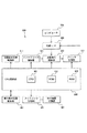
図11は、複写機10の制御装置800のブロック図である。   FIG. 11 is a block diagram of the control device 800 of the copying machine 10.

制御装置800は、複写機10全体を制御するCPU回路部900を備えている。CPU回路部900は、CPU901、ROM902及びRAM903を有し、ROM902には、制御プログラムが格納されている。   The control device 800 includes a CPU circuit unit 900 that controls the entire copying machine 10. The CPU circuit unit 900 includes a CPU 901, a ROM 902, and a RAM 903, and the ROM 902 stores a control program.

CPU回路部900は、制御プログラム及び操作表示装置制御部941の設定に従い、原稿給送装置制御部911、イメージリーダ制御部921、画像信号制御部922、プリンタ制御部931を制御する。更に、CPU回路部900は、制御プログラム及び操作表示装置制御部941の設定に従い、フィニッシャ制御部951及び折り装置制御部961を制御する。   The CPU circuit unit 900 controls the document feeder control unit 911, the image reader control unit 921, the image signal control unit 922, and the printer control unit 931 according to the settings of the control program and the operation display device control unit 941. Further, the CPU circuit unit 900 controls the finisher control unit 951 and the folding device control unit 961 according to the settings of the control program and the operation display device control unit 941.

RAM903は、制御データを一時的に保持し、また制御に伴う演算処理の作業領域として用いられる。   The RAM 903 temporarily stores control data and is used as a work area for arithmetic processing associated with control.

原稿給送装置制御部911は、原稿給送装置100をCPU回路部900からの指示に基づき駆動制御する。イメージリーダ制御部921は、上述のスキャナユニット104、イメージセンサ109などに対する駆動制御を行い、イメージセンサ109から出力されたアナログ画像信号を画像信号制御部922に転送する。   The document feeder control unit 911 drives and controls the document feeder 100 based on an instruction from the CPU circuit unit 900. The image reader control unit 921 performs drive control on the scanner unit 104 and the image sensor 109 described above, and transfers an analog image signal output from the image sensor 109 to the image signal control unit 922.

画像信号制御部922は、イメージセンサ109からのアナログ画像信号をデジタル信号に変換した後に各処理を施し、このデジタル信号をビデオ信号に変換してプリンタ制御部931に出力する。また、コンピュータ904から外部I/F905を介して入力されたデジタル画像信号に各種処理を施し、このデジタル画像信号をビデオ信号に変換してプリンタ制御部931に出力する。この画像信号制御部922による処理動作は、CPU回路部900により制御される。プリンタ制御部931は、入力されたビデオ信号に基づき上述の露光制御部110を駆動する。   The image signal control unit 922 performs each process after converting the analog image signal from the image sensor 109 into a digital signal, converts the digital signal into a video signal, and outputs the video signal to the printer control unit 931. Further, the digital image signal input from the computer 904 via the external I / F 905 is subjected to various processes, and the digital image signal is converted into a video signal and output to the printer control unit 931. The processing operation by the image signal control unit 922 is controlled by the CPU circuit unit 900. The printer control unit 931 drives the above-described exposure control unit 110 based on the input video signal.

操作表示装置制御部401は、操作表示装置400とCPU回路部900との間で情報のやり取りを行う。操作表示装置400(図1)は、画像形成に関する各種機能を設定する複数のキー、設定状態を示す情報を表示するための表示部などを有している。そして操作表示装置400(図1)は、各キーの操作に対応するキー信号を、CPU回路部900に出力するとともに、CPU回路部900からの信号に基づき対応する情報を表示部に表示する。   The operation display device control unit 401 exchanges information between the operation display device 400 and the CPU circuit unit 900. The operation display device 400 (FIG. 1) includes a plurality of keys for setting various functions relating to image formation, a display unit for displaying information indicating a setting state, and the like. The operation display device 400 (FIG. 1) outputs a key signal corresponding to the operation of each key to the CPU circuit unit 900 and displays corresponding information on the display unit based on the signal from the CPU circuit unit 900.

制御手段としてのフィニッシャ制御部951は、フィニッシャ500に搭載され、CPU回路部900と情報のやり取りを行うことによってフィニッシャ500全体の駆動制御を行う。この制御内容については後述する。   A finisher control unit 951 serving as a control unit is mounted on the finisher 500 and performs drive control of the entire finisher 500 by exchanging information with the CPU circuit unit 900. This control content will be described later.

折り装置制御部961はシート折り装置700に搭載され、フィニッシャ制御部951と情報のやり取りを行いシート折り装置700全体の駆動制御を行う。   The folding device control unit 961 is mounted on the sheet folding device 700, exchanges information with the finisher control unit 951, and performs drive control of the entire sheet folding device 700.

次に、操作表示装置400について詳細に説明する。図12は、複写機10における操作表示装置400を示す説明図である。   Next, the operation display device 400 will be described in detail. FIG. 12 is an explanatory diagram showing the operation display device 400 in the copying machine 10.

操作表示装置400には、画像形成動作を開始するためのスタートキー402、画像形成動作を中断するためのストップキー403、置数設定等を行うテンキー404〜413、IDキー414、クリアキー415、リセットキー416などが配置されている。また、上部にタッチパネルが形成された液晶の表示部420が配置されており、画面上にソフトキーを作成可能となっている。   The operation display device 400 includes a start key 402 for starting an image forming operation, a stop key 403 for interrupting the image forming operation, ten keys 404 to 413 for setting numerical values, an ID key 414, a clear key 415, A reset key 416 and the like are arranged. In addition, a liquid crystal display unit 420 having a touch panel formed thereon is disposed, and a soft key can be created on the screen.

複写機10は、後処理モードとしてノンソート、ソート、ステイプルソート(綴じモード)、製本モードなどの各処理モードを有する。このような処理モードの設定などは操作表示装置400からの入力操作により行われる。例えば、後処理モードを設定する際には、図12に示す初期画面でソフトキーである「ソータ」を選択すると、メニュー選択画面が表示部420に表示され、このメニュー選択画面を用いて処理モードの設定が行われる。   The copying machine 10 has various processing modes such as non-sorting, sorting, stapling sorting (binding mode), and bookbinding mode as post-processing modes. Such setting of the processing mode is performed by an input operation from the operation display device 400. For example, when setting the post-processing mode, when the “sorter” soft key is selected on the initial screen shown in FIG. 12, a menu selection screen is displayed on the display unit 420, and the processing mode is selected using this menu selection screen. Is set.

次に、操作表示装置400における製本モードの流れについて説明する。図13〜図18は、操作表示装置400の表示部420を示す説明図である。   Next, the flow of the bookbinding mode in the operation display device 400 will be described. 13 to 18 are explanatory diagrams illustrating the display unit 420 of the operation display device 400.

まず、ユーザにより図12に示す初期画面でソフトキーである「応用モード」が選択されると、表示部420が図13に示すような各種モードを選択する画面に切り換わる。この状態で「製本」がユーザにより選択されると、図14に示すように、使用するサイズのシートPを選択可能なキーが表示される。   First, when the user selects the “applied mode” soft key on the initial screen shown in FIG. 12, the display unit 420 switches to a screen for selecting various modes as shown in FIG. When “bookbinding” is selected by the user in this state, as shown in FIG. 14, a key capable of selecting a sheet P of a size to be used is displayed.

ここで、複写機本体300の各カセットには、それぞれ異なるサイズのシートPが格納されており、ユーザは、使用するシートPが格納されているカセットを選択することとなる。   Here, sheets P of different sizes are stored in the respective cassettes of the copying machine main body 300, and the user selects a cassette storing the sheets P to be used.

そして、ユーザによりカセット(図14では、「A3」のカセット)が選択され、「次へ」のソフトキーが押下されると、図15に示すように、製本するシート束に対する処理を設定する画面となる。   When the user selects a cassette ("A3" cassette in FIG. 14) and presses the "Next" soft key, a screen for setting processing for a bundle of sheets to be bound as shown in FIG. It becomes.

製本モードが選択された場合、少なくともシート束の中折りを行うが、中綴じ処理を行うか否かはユーザが選択可能であり、ユーザは、「中綴じする」と「中綴じしない」のいずれかのソフトキーを選択する。更に、中綴じ処理とは独立に、シート束の中紙に対して折りシートを使用するか否かを選択可能となっている。   When the bookbinding mode is selected, at least the sheet bundle is folded, but the user can select whether or not to perform the saddle stitching process. The user can select either “saddle stitching” or “not saddle stitching”. Select the soft key. Furthermore, independent of the saddle stitching process, it is possible to select whether or not to use a folded sheet for the middle sheet of the sheet bundle.

ここで、中綴じ処理の設定に拘らず、「折り紙を挿入しない」が選択され、「OK」キーが押されると設定が終了する。   Here, regardless of the setting of the saddle stitching process, when “Don't insert origami” is selected and the “OK” key is pressed, the setting is completed.

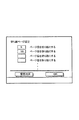
また、中綴じ処理の設定に拘らず、「折り紙を挿入する」が選択され、「OK」キーが押されると、次に、図16の折りシートの挿入ページを設定する画面となり、折りシートを使用するページの設定を行う。   If “insert origami” is selected and the “OK” key is pressed regardless of the setting of the saddle stitching process, a screen for setting a page for inserting a folded sheet shown in FIG. Set the page to be used.

折りシートのページ設定は、複数ページ設定可能となっており、折りシートを入れたいページ数を入力する。図16で折りシートのページ設定が終了すると、図17で、折りシートで使用するカセットを選択する。折りシートとして使用するカセットを選択し、「OK」キーが押されると、次に図18で折り返し部の長さの設定を行う。ここで設定された折り返し部の長さを含む折りシート情報に基づいて、後述するシート押え部材の位置を決定する。   The page setting of the folded sheet can be set to a plurality of pages, and the number of pages into which the folded sheet is to be input is input. When the page setting of the folded sheet is completed in FIG. 16, the cassette used for the folded sheet is selected in FIG. When a cassette to be used as a folded sheet is selected and the “OK” key is pressed, the length of the folded portion is set in FIG. Based on the folded sheet information including the length of the folded portion set here, the position of a sheet pressing member described later is determined.

図19は、フィニッシャ500におけるシート積載部530近傍を示す概略斜視図である。   FIG. 19 is a schematic perspective view showing the vicinity of the sheet stacking unit 530 in the finisher 500.

フィニッシャ500は、シート積載部530においてシート搬送方向(矢印A方向)と直交する幅方向(矢印B方向)のそれぞれの端部近傍に配置される一対のシート押えユニット595a,595bを備えている。各シート押えユニット595a,595bは、シート積載部530の幅方向中心に対して左右対称に配置されている。ここで、図19に示すシート押えユニット595a,595bの各XYZ直交座標は、シート積載部530の幅方向中心に対して左右対称である。   The finisher 500 includes a pair of sheet pressing units 595a and 595b disposed in the vicinity of the respective end portions in the width direction (arrow B direction) orthogonal to the sheet conveyance direction (arrow A direction) in the sheet stacking unit 530. The sheet pressing units 595a and 595b are arranged symmetrically with respect to the center in the width direction of the sheet stacking unit 530. Here, the XYZ orthogonal coordinates of the sheet pressing units 595 a and 595 b shown in FIG. 19 are symmetrical with respect to the center in the width direction of the sheet stacking unit 530.

シート押えユニット595a,595bは、シート押え部材590a,590bを備えている。また、シート押えユニット595a,595bは、シート押え部材590a,590bをシート搬送方向と直交する方向(X,Z方向及びX,Z方向と反対の−X,−Z方向)に移動させる交差移動手段としての交差移動部600a,600bを備えている。また、フィニッシャ500は、シート押えユニット595a,595bをそれぞれシート搬送方向と平行な方向(Y方向及びY方向と反対の−Y方向)に移動させる平行移動手段として平行移動部610a,610bを備えている。そして、平行移動手段としての平行移動部610a,610bと、交差移動手段としての交差移動部600a,600bとによりシート押え部材590a,590bを移動させる移動手段が構成されている。ここで、製本処理トレイ560は、略垂直に傾斜して配置されており、平行移動部610a,610bは、略垂直方向に移動することとなり、交差移動部600a,600bは、略水平方向に移動することとなる。   The sheet pressing units 595a and 595b include sheet pressing members 590a and 590b. Further, the sheet pressing units 595a and 595b are cross moving means for moving the sheet pressing members 590a and 590b in a direction orthogonal to the sheet conveying direction (X, Z direction and -X, -Z direction opposite to the X, Z direction). Are provided with cross moving parts 600a and 600b. Further, the finisher 500 includes parallel moving units 610a and 610b as parallel moving means for moving the sheet pressing units 595a and 595b in directions parallel to the sheet conveying direction (Y direction and -Y direction opposite to the Y direction), respectively. Yes. The parallel moving units 610a and 610b as the parallel moving means and the cross moving units 600a and 600b as the cross moving means constitute moving means for moving the sheet pressing members 590a and 590b. Here, the bookbinding tray 560 is inclined substantially vertically, the parallel moving portions 610a and 610b move in a substantially vertical direction, and the cross moving portions 600a and 600b move in a substantially horizontal direction. Will be.

シート押え部材590a,590bは、シート積載部530に積載されているシート束を押える押え位置と、シート束から離間すると共にシート搬送方向と直交する幅方向に退避する退避位置とに移動可能にシート位置決め部材554の上方に配置されている。   The sheet pressing members 590a and 590b are movably moved between a pressing position for pressing the sheet bundle stacked on the sheet stacking unit 530 and a retreat position that is separated from the sheet bundle and retracts in the width direction orthogonal to the sheet conveying direction. It is disposed above the positioning member 554.

また、シート押え部材590a,590bは、積載部本体側である製本処理トレイ560側にシート束を押し付ける押付面590Aと、押付面590Aの反対側に形成され、シートをシート位置決め部材554に案内する案内面590Bとを有している。各シート押え部材590a,590bの案内面590Bは、シート搬送方向上流側(矢印Y方向)に向かって製本処理トレイ560側に傾斜する傾斜面である。   The sheet pressing members 590a and 590b are formed on the pressing surface 590A for pressing the sheet bundle to the bookbinding processing tray 560 which is the stacking unit main body side, and on the opposite side of the pressing surface 590A, and guides the sheet to the sheet positioning member 554. And a guide surface 590B. The guide surfaces 590B of the sheet pressing members 590a and 590b are inclined surfaces that incline toward the bookbinding tray 560 toward the upstream side in the sheet conveyance direction (arrow Y direction).

交差移動部600a,600bは、それぞれモータM13,M14と、モータM13,M14の駆動力を伝達するベルト596a,596bとを備えている。更に、交差移動部600a,600bは、それぞれ略円盤形状に形成され、ベルト596a,596bによりシート搬送方向に平行な回動軸を中心に回動するカム部材591a,591bを備えている。更に、交差移動部600a,600bは、それぞれ基端がL字形状に屈曲してカム部材591a,591bに取り付けられ、先端がシート押え部材590a,590bに取り付けられる軸594a,594bを備えている。   The cross moving units 600a and 600b include motors M13 and M14, and belts 596a and 596b that transmit driving forces of the motors M13 and M14, respectively. Furthermore, the cross moving parts 600a and 600b are formed in a substantially disc shape, respectively, and include cam members 591a and 591b that are rotated by belts 596a and 596b about a rotation axis parallel to the sheet conveying direction. Further, the cross moving parts 600a and 600b are respectively provided with shafts 594a and 594b which are bent at L-shaped base ends and attached to the cam members 591a and 591b, and the tip ends are attached to the sheet pressing members 590a and 590b.

図20及び図21は、交差移動部600a,600bによるシート押え部材590a,590bの移動動作を示す説明図である。   20 and 21 are explanatory views showing the movement operation of the sheet pressing members 590a and 590b by the cross moving portions 600a and 600b.

モータM13,M14が駆動すると、その駆動力がベルト596a,596b(図19)を介してカム部材591a,591bに伝達され、カム部材591a,591bが回動し、シート押え部材590a,590bが軸594a,594bを介して動作する。   When the motors M13 and M14 are driven, the driving force is transmitted to the cam members 591a and 591b via the belts 596a and 596b (FIG. 19), the cam members 591a and 591b rotate, and the sheet pressing members 590a and 590b are pivoted. It operates via 594a and 594b.

具体的に説明すると、シート押え部材590a,590bは、カム部材591a,591bが回動することにより、シート搬送方向と直交する幅方向(X方向及びX方向と反対の−X方向)に移動する。更に、シート押え部材590a,590bは、カム部材591a,591bが回動することにより、製本処理トレイ560上に積載されたシート束に接離する接離方向(Z方向及びZ方向と反対の−Z方向)に移動する。このカム部材591a,591bの回動動作により、シート押え部材590a,590bは押え位置(図20)と退避位置(図21)との間を移動することとなる。つまり、交差移動部600a,600bのモータM13,M14を順方向に駆動することにより、カム部材591a,591bが順方向に回動し、シート押え部材590a,590bが、退避位置から−X/−Z方向に移動して押え位置(図20)に移動する。逆に、交差移動部600a,600bのモータM13,M14を逆方向に駆動することにより、カム部材591a,591bが逆方向に回動し、シート押え部材590a,590bが、押え位置からX/Z方向に移動して退避位置(図21)に移動する。   More specifically, the sheet pressing members 590a and 590b move in the width direction (the X direction and the −X direction opposite to the X direction) orthogonal to the sheet conveying direction by rotating the cam members 591a and 591b. . Further, the sheet pressing members 590a and 590b are moved toward and away from the sheet bundle stacked on the bookbinding processing tray 560 (as opposed to the Z direction and the Z direction) by rotating the cam members 591a and 591b. Z direction). As the cam members 591a and 591b rotate, the sheet pressing members 590a and 590b move between the pressing position (FIG. 20) and the retracted position (FIG. 21). That is, by driving the motors M13 and M14 of the cross moving portions 600a and 600b in the forward direction, the cam members 591a and 591b are rotated in the forward direction, and the sheet pressing members 590a and 590b are moved from the retracted position to −X / −. It moves in the Z direction and moves to the presser position (FIG. 20). On the contrary, by driving the motors M13 and M14 of the cross moving parts 600a and 600b in the reverse direction, the cam members 591a and 591b are rotated in the reverse direction, and the sheet pressing members 590a and 590b are moved from the press position to the X / Z. It moves in the direction and moves to the retracted position (FIG. 21).

なお、本実施の形態では、各モータM13,M14により各シート押え部材590a,590bを動作させているが、これに限らず、1つのモータで一対のシート押え部材590a,590bを動作させてもよい。   In this embodiment, the sheet pressing members 590a and 590b are operated by the motors M13 and M14. However, the present invention is not limited to this, and the pair of sheet pressing members 590a and 590b may be operated by one motor. Good.

図22は、平行移動部610a,610bによるシート押え部材590a,590bの移動動作を示す説明図である。   FIG. 22 is an explanatory diagram showing the movement operation of the sheet pressing members 590a and 590b by the parallel moving portions 610a and 610b.

シート押え部材590a,590bは、平行移動部610a,610bによりシート搬送方向に沿って移動可能である。つまり、シート押えユニット595a,595bがシート搬送方向に沿って移動することにより、シート押え部材590a,590bがシート搬送方向に沿って移動する。   The sheet pressing members 590a and 590b can be moved along the sheet conveying direction by the parallel moving portions 610a and 610b. That is, as the sheet pressing units 595a and 595b move along the sheet conveying direction, the sheet pressing members 590a and 590b move along the sheet conveying direction.

平行移動部610a,610bは、それぞれシート積載部530の幅方向の端部近傍に配置されるモータM10,M11と、モータM10,M11の駆動力をシート押えユニット595a,595bに伝達するベルト593a,593bとを有している。そして、モータM10、M11の駆動により、シート押えユニット595a,595b(即ち、シート押え部材590a,590b)は、シート搬送方向に対して平行方向に移動可能となっている。   The translation units 610a and 610b include motors M10 and M11 disposed near the width direction end of the sheet stacking unit 530, and belts 593a and 593a that transmit the driving force of the motors M10 and M11 to the sheet pressing units 595a and 595b, respectively. 593b. The sheet pressing units 595a and 595b (that is, the sheet pressing members 590a and 590b) are movable in a direction parallel to the sheet conveying direction by driving the motors M10 and M11.

なお、本実施の形態では、各モータM10,M11により各シート押えユニット595a,595bを動作させているが、これに限らず、1つのモータで一対のシート押えユニット595a,595bを動作させてもよい。   In this embodiment, the sheet pressing units 595a and 595b are operated by the motors M10 and M11. However, the present invention is not limited to this, and the pair of sheet pressing units 595a and 595b may be operated by one motor. Good.

ここで、各交差移動部600a,600b及び各平行移動部610a,610bは、制御手段としてのフィニッシャ制御部951(図11)により駆動制御される。   Here, the cross moving units 600a and 600b and the parallel moving units 610a and 610b are driven and controlled by a finisher control unit 951 (FIG. 11) as control means.

ところで、製本モードが選択されている場合は、図6〜図10を参照して説明したように、最終的にシート積載部530に積載されているシート束を折りローラ対556で折り曲げて製本する。また、図15において説明した中綴じ処理の設定がされた場合は、シート積載部530に積載されたシート束にステイプラ555で中綴じ処理が行われる。このように、シート束に処理を施して製本する場合には、シート束の整合性が重要となる。つまり、製本してしまうと、その後に乱れているシートを修正しようとしても修正が困難である。   By the way, when the bookbinding mode is selected, as described with reference to FIGS. 6 to 10, the sheet bundle finally stacked on the sheet stacking unit 530 is folded by the folding roller pair 556 for bookbinding. . When the saddle stitching process described in FIG. 15 is set, the stapler 555 performs the saddle stitching process on the sheet bundle stacked on the sheet stacking unit 530. Thus, when the sheet bundle is processed and bound, the consistency of the sheet bundle is important. In other words, once the book is bound, it is difficult to correct it even if an attempt is made to correct the disordered sheet thereafter.

そこで、本実施の形態では、シート押え部材590a,590bを以下のように動作させている。   Therefore, in the present embodiment, the sheet pressing members 590a and 590b are operated as follows.

図23は、製本モードが選択された場合のフィニッシャ制御部951によるシート積載処理の制御動作を示すフローチャートである。図24は、シート押え部材590a,590bを折りシートPの折り端部Paに移動させる動作を示す説明図である。図25は、シート押え部材590a,590bを退避位置から押え位置に移動させている途中を示す説明図である。図26は、シート押え部材590a,590bを押え位置に移動させた状態で次のシートP’が搬送されてきた場合を示す説明図である。図27は、シート押え部材590a,590bを押え位置から退避位置に移動させる動作を示す説明図である。   FIG. 23 is a flowchart showing a control operation of the sheet stacking process by the finisher control unit 951 when the bookbinding mode is selected. FIG. 24 is an explanatory diagram illustrating an operation of moving the sheet pressing members 590a and 590b to the folded end portion Pa of the folded sheet P. FIG. 25 is an explanatory diagram showing a state in which the sheet pressing members 590a and 590b are being moved from the retracted position to the pressing position. FIG. 26 is an explanatory diagram showing a case where the next sheet P ′ is conveyed in a state where the sheet pressing members 590a and 590b are moved to the pressing position. FIG. 27 is an explanatory diagram illustrating an operation of moving the sheet pressing members 590a and 590b from the pressing position to the retracted position.

なお、本実施の形態で各シート押え部材590a,590bの初期位置(ホームポジション)は退避位置である。   In the present embodiment, the initial position (home position) of each sheet pressing member 590a, 590b is the retracted position.

以下、図23のフローチャートに沿って、図24〜図27を参照しながら説明する。   Hereinafter, it demonstrates along the flowchart of FIG. 23, referring FIGS. 24-27.

まず、フィニッシャ制御部951(図11)は、搬送ローラ対552を動作させてシート積載部530に搬送し、1枚目のシートPの積載を完了させる(S1)。   First, the finisher control unit 951 (FIG. 11) operates the conveyance roller pair 552 to convey the sheet to the sheet stacking unit 530 and complete the stacking of the first sheet P (S1).

次に、フィニッシャ制御部951は、シート積載部530に搬送されたシートPが折りシートであるか、又は積載済みのシート束の中に折りシートが含まれているか否かを判断する(S2)。   Next, the finisher control unit 951 determines whether the sheet P conveyed to the sheet stacking unit 530 is a folded sheet or whether the stacked sheet bundle includes a folded sheet (S2). .

フィニッシャ制御部951は、シート積載部530に搬送されたシートPが折りシートであると判断した場合(S2:Yes)、図24(a)の如く、折り端部Paと対応する位置にシート押え部材590a,590bをY方向又は−Y方向に移動させる(S3)。   When the finisher control unit 951 determines that the sheet P conveyed to the sheet stacking unit 530 is a folded sheet (S2: Yes), the sheet presser is positioned at a position corresponding to the folded end portion Pa as shown in FIG. The members 590a and 590b are moved in the Y direction or the −Y direction (S3).

ここで、折りシートPの折り端部Paとは、シートを折った場合の折り目と反対側の2つの端部の内、折りシートPにおけるシート搬送方向の折り返し部の長さが短い方の折り端部Paのことである。そして、本実施の形態では、折りシートPは、シート搬送方向と直交する方向の折り目がシート搬送方向下流側となるようにシート積載部530に搬送される。   Here, the folding end portion Pa of the folded sheet P refers to the folding of the shorter end portion of the folded sheet P in the sheet conveying direction among the two ends opposite to the fold when the sheet is folded. It is the end Pa. In the present embodiment, the folded sheet P is conveyed to the sheet stacking unit 530 so that the fold in the direction orthogonal to the sheet conveying direction is on the downstream side in the sheet conveying direction.

また、フィニッシャ制御部951は、シート積載部530に積載済みのシート束の中に折りシートが含まれていると判断した場合(S2:Yes)、折り端部Paと対応する位置にシート押え部材590a,590bをY方向又は−Y方向に移動させる(S3)。シート積載部530に積載されているシート束に複数の折りシートが含まれている場合には、複数の折りシートのうち、最上部に位置する折りシートの折り端部に対応する位置にシート押え部材590a,590bを移動させている。このようにS3においては、平行移動部610a,610bにより、シート押え部材590a,590bを折り端部Paの位置に応じて移動させている。   Further, when the finisher control unit 951 determines that the folded sheet is included in the sheet bundle already stacked on the sheet stacking unit 530 (S2: Yes), the sheet pressing member is positioned at a position corresponding to the folded end portion Pa. 590a and 590b are moved in the Y direction or -Y direction (S3). When a plurality of folded sheets are included in the sheet bundle stacked on the sheet stacking unit 530, the sheet presser is positioned at a position corresponding to the folded end portion of the folded sheet positioned at the top of the plurality of folded sheets. The members 590a and 590b are moved. As described above, in S3, the sheet pressing members 590a and 590b are moved according to the position of the folded end portion Pa by the parallel moving portions 610a and 610b.

ここで、図24(b)に示すように、折りシートPの折り端部Paと対応する位置とは異なる位置にシート押え部材590a,590bを移動させた状態で押え位置に移動させたと仮定する。これでは、折りシートPがカールしている場合には、折りシートPの折り端部Paが次に搬送されてきたシートに引っ掛って折れ曲がり、また、シート束の整合性が損なわれてしまうおそれがある。   Here, as shown in FIG. 24B, it is assumed that the sheet pressing members 590a and 590b are moved to the pressing position in a state where the sheet pressing members 590a and 590b are moved to positions different from the positions corresponding to the folding end portion Pa of the folded sheet P. . In this case, when the folded sheet P is curled, the folded end portion Pa of the folded sheet P is caught by the next conveyed sheet and bent, and the consistency of the sheet bundle may be impaired. There is.

これに対し、本実施の形態では、図24(a)に示すように、フィニッシャ制御部951は、シート搬送方向においてシート積載部530に積載されている折りシートPの折り端部Paに対応する位置にシート押え部材590a,590bを移動させる。具体的に説明すると、フィニッシャ制御部951は、折りシート情報に基づいて、モータM10,M11(図19)を駆動し、シート積載部530に積載されている折りシートPの折り端部Paに対応する位置にシート押え部材590a,590bを移動させる。ここで、折りシート情報は、図18を参照して説明した、ユーザにより設定された折り返し部のシート搬送方向の長さを示す情報である。これにより、折りシートPの折り端部Pa側が外側にカールしていても、折り端部Paがシート押え部材590a,590bにより押え付けられることとなるので、積載不良を抑制することができる。これにより、シートの整合性の低下を防止でき、ひいては製本物の品位低下を防止できる。   On the other hand, in this embodiment, as shown in FIG. 24A, the finisher control unit 951 corresponds to the folded end portion Pa of the folded sheet P stacked on the sheet stacking unit 530 in the sheet conveying direction. The sheet pressing members 590a and 590b are moved to the positions. More specifically, the finisher control unit 951 drives the motors M10 and M11 (FIG. 19) based on the folded sheet information, and corresponds to the folded end portion Pa of the folded sheet P stacked on the sheet stacking unit 530. The sheet pressing members 590a and 590b are moved to the positions to be moved. Here, the folded sheet information is information indicating the length in the sheet conveyance direction of the folded portion set by the user, as described with reference to FIG. Accordingly, even if the folded end portion Pa side of the folded sheet P is curled outward, the folded end portion Pa is pressed by the sheet pressing members 590a and 590b, and thus stacking failure can be suppressed. Thereby, the fall of the integrity of a sheet | seat can be prevented and by extension, the quality fall of a bookbinding product can be prevented.

また、S3でシート押え部材590a,590bを退避位置に退避させた状態でシート押え部材590a,590bをY方向又は−Y方向に移動させるようにしたので、シート押え部材590a,590bがシート表面を擦りながら摺動することはない。従って、シートの整合性が低下することはなく、また、シート表面に形成された画像の品質が低下することがない。なお、シート押え部材590a,590bの押付面590Aが滑らかな摺動面であり、シートの汚損や整合性の低下のおそれがない場合は、シート押え部材590a,590bを押え位置に移動させた状態でY方向又は−Y方向に移動させてもよい。   In S3, since the sheet pressing members 590a and 590b are moved in the Y direction or the −Y direction with the sheet pressing members 590a and 590b retracted to the retracted position, the sheet pressing members 590a and 590b move the sheet surface. There is no sliding while rubbing. Accordingly, the sheet alignment does not deteriorate, and the quality of the image formed on the sheet surface does not deteriorate. When the pressing surfaces 590A of the sheet pressing members 590a and 590b are smooth sliding surfaces, and there is no risk of sheet contamination or deterioration of alignment, the sheet pressing members 590a and 590b are moved to the pressing position. May be moved in the Y direction or -Y direction.

なお、フィニッシャ制御部951は、既にシート積載部530に積載されている折り端部Paに対応する位置にシート押え部材590a,590bが移動している場合は、移動させる必要はないので、シート押え部材590a,590bをその位置に保持する。   Note that the finisher control unit 951 does not need to move the sheet pressing members 590a and 590b to the position corresponding to the folded end portion Pa already stacked on the sheet stacking unit 530, and therefore, the sheet pressing unit 951 is not required to move. The members 590a and 590b are held in that position.

本実施の形態では、折りシートPの折り端部Paに対応する位置として、シート押え部材590a,590bが折りシートPの折り端部Paを跨ぐ位置にシート押え部材590a,590bを移動させている。これによって、折りシートPを効果的に押えることができ、次のシートP’が搬送されてきても、次のシートP’が折りシートPの折り開口側に入り込むことはない。   In the present embodiment, the sheet pressing members 590a and 590b are moved to positions where the sheet pressing members 590a and 590b straddle the folding end portion Pa of the folded sheet P as positions corresponding to the folding end portion Pa of the folded sheet P. . Accordingly, the folded sheet P can be effectively pressed, and even if the next sheet P ′ is conveyed, the next sheet P ′ does not enter the folding opening side of the folded sheet P.

次いで、フィニッシャ制御部951は、S3の後、シート押え部材590a,590bを、図25に示すように、押え位置に移動させる(S4)。具体的に説明すると、フィニッシャ制御部951は、モータM13,M14(図19)を駆動してカム部材591a,591bを順方向に回動させてシート押え部材590a,590bを退避位置から−X/−Z方向に移動させて押え位置に移動させている。このように、シートP’がシート積載部530に搬送される前に、シート押え部材590a,590bを押え位置に移動させて、先にシート積載部530に積載されたシートPを押えている。   Next, after S3, the finisher control unit 951 moves the sheet pressing members 590a and 590b to the pressing position as shown in FIG. 25 (S4). Specifically, the finisher control unit 951 drives the motors M13 and M14 (FIG. 19) to rotate the cam members 591a and 591b in the forward direction to move the sheet pressing members 590a and 590b from the retracted position to −X / -Moved in the -Z direction to the presser position. As described above, before the sheet P ′ is conveyed to the sheet stacking unit 530, the sheet pressing members 590 a and 590 b are moved to the pressing position to press the sheet P previously stacked on the sheet stacking unit 530.

S4で折りシートPの折り端部Paを押えた後、フィニッシャ制御部951は、図26に示すように、搬送ローラ対552を動作させて次のシートP’をシート積載部530に搬送し、次のシートP’の積載を完了させる(S5)。   After pressing the folded end portion Pa of the folded sheet P in S4, the finisher control unit 951 operates the conveying roller pair 552 to convey the next sheet P ′ to the sheet stacking unit 530, as shown in FIG. The stacking of the next sheet P ′ is completed (S5).

このとき、シート押え部材590a,590bがシート束を押えている状態であるが、次のシートP’はシート押え部材590a,590bの案内面590Bによりスムーズにシート位置決め部材554に案内される。従って、シートP’はシート押え部材590a,590bに引っ掛ることはないので、シートの積載不良が防止され、これにより、シート束の整合性の低下が防止され、ひいては製本物の品位の低下が防止される。   At this time, although the sheet pressing members 590a and 590b are pressing the sheet bundle, the next sheet P 'is smoothly guided to the sheet positioning member 554 by the guide surfaces 590B of the sheet pressing members 590a and 590b. Accordingly, since the sheet P ′ is not caught by the sheet pressing members 590a and 590b, the sheet stacking failure is prevented, thereby preventing the sheet bundle alignment from being deteriorated, and hence the quality of the bookbinding product. Is prevented.

このとき、シート押え部材590a,590bは、シートPとシートP’との間に挟まれている状態である。次に、フィニッシャ制御部951は、図27に示すように、シート押え部材590a,590bを押え位置からX/Z方向へ移動させて退避位置に移動させる(S6)。つまり、シート押え部材590a,590bは、Z方向へ移動することにより、シートPの表面から離間し、更に、X方向へ移動することにより、シートPとシートP’の間から退避することとなる。これにより、シート押え部材590a,590bを退避させる際に、シートP’の脱落やシートP’の積載不良が抑制される。   At this time, the sheet pressing members 590a and 590b are sandwiched between the sheet P and the sheet P '. Next, as shown in FIG. 27, the finisher control unit 951 moves the sheet pressing members 590a and 590b from the pressing position in the X / Z direction to the retracted position (S6). That is, the sheet pressing members 590a and 590b move away from the surface of the sheet P by moving in the Z direction, and further retreat from between the sheet P and the sheet P ′ by moving in the X direction. . Accordingly, when the sheet pressing members 590a and 590b are retracted, the sheet P 'is not dropped and the sheet P' is not stacked properly.

次に、フィニッシャ制御部951は、設定された製本に必要な全てのシートがシート積載部530に積載完了したか否かを判断する(S8)。積載完了した場合(S8:Yes)は、製本モードにおける積載処理を終了し、製本動作に移行する。積載完了していない場合(S8:No)は、S2に移行する。S2で、シート積載部530に搬送されたシートPが折りシートではなく、且つ積載済みのシート束の中に折りシートが含まれていない場合(S2:No)、フィニッシャ制御部951は、次のシートをシート積載部530に搬送して積載を完了させる(S7)。次いで、S8に移行する。   Next, the finisher control unit 951 determines whether or not all the sheets necessary for the set bookbinding have been stacked on the sheet stacking unit 530 (S8). When the stacking is completed (S8: Yes), the stacking process in the bookbinding mode is terminated and the bookbinding operation is started. If the loading is not completed (S8: No), the process proceeds to S2. In S2, when the sheet P conveyed to the sheet stacking unit 530 is not a folded sheet and a folded sheet is not included in the stacked sheet bundle (S2: No), the finisher control unit 951 The sheet is conveyed to the sheet stacking unit 530 to complete stacking (S7). Next, the process proceeds to S8.

つまり、シート束の最上位に折りシートがある場合のみならず、本実施の形態では、シート束に折りシートが含まれている場合(S2:Yes)でも、シート積載部530のシート束をシート押え部材590a,590bで押えるようにしている。これは、折りシートがシート束に含まれることにより、シート束が膨らんでしまうことがあるからである。これにより、シート束に含まれている折りシートによりシート束が膨むような場合でも、シート押え部材590a,590bによりシート束の膨らみが抑制される。従って、シート束に搬送されてきたシートが入り込むのを防止することができ、積載不良を防止することができる。これにより、シート束の整合性の低下を防止することができ、ひいては製本物の品位低下を防止することができる。   That is, not only when there is a folded sheet at the top of the sheet bundle, but also in the present embodiment, when the folded sheet is included in the sheet bundle (S2: Yes), the sheet bundle of the sheet stacking unit 530 is used as the sheet. The pressing members 590a and 590b are used for pressing. This is because the sheet bundle may swell when the folded sheet is included in the sheet bundle. Thereby, even when the sheet bundle is swollen by the folded sheets included in the sheet bundle, the swollenness of the sheet bundle is suppressed by the sheet pressing members 590a and 590b. Accordingly, it is possible to prevent the sheet conveyed to the sheet bundle from entering, and to prevent a stacking failure. As a result, it is possible to prevent a decrease in the consistency of the sheet bundle, and as a result, it is possible to prevent a decrease in quality of the bookbinding product.

以上、本実施の形態によれば、シートP’がシート積載部530に搬送される前にシート押え部材590a,590bを押え位置に移動させて先にシート積載部に積載されたシートPを押えたことにより、シート積載部530のシート束の膨らみが抑制される。そして、シートPを押えた状態で次のシートP’がシート積載部530に搬送されたときは、シートPの折り端部Paに引っ掛ったり、折りシートであるシートPの折り開口側にシートP’が入り込んだりするのを防止することができる。これにより、シート束の整合性の低下を防止することができる。そして、製本する際には、シート束の整合性の低下が防止されているので、製本物の品位低下を防止することができる。   As described above, according to the present embodiment, before the sheet P ′ is conveyed to the sheet stacking unit 530, the sheet pressing members 590a and 590b are moved to the pressing position to press the sheet P previously stacked on the sheet stacking unit. As a result, the swelling of the sheet bundle of the sheet stacking unit 530 is suppressed. Then, when the next sheet P ′ is conveyed to the sheet stacking unit 530 with the sheet P being pressed, the sheet P is caught on the folding end portion Pa of the sheet P, or on the folding opening side of the sheet P which is a folded sheet. P ′ can be prevented from entering. Thereby, it is possible to prevent a decrease in the consistency of the sheet bundle. And when bookbinding, since the fall of the consistency of a sheet bundle is prevented, the quality reduction of a bookbinding product can be prevented.

なお、上記実施の形態に基づいて本発明を説明したが、本発明はこれに限定されるものではない。   Although the present invention has been described based on the above embodiment, the present invention is not limited to this.

上記実施の形態では、シート搬送方向と直交する方向に折り目を有する折りシートを押える構成について説明したが、シート搬送方向と平行な方向に折り目を有する折りシートを押える構成においても本発明は有効である。また、折りシートの折り目がシート搬送方向下流側となるようにシート積載部に搬送される場合について説明したが、折りシートの折り目がシート搬送方向上流側となるようにシート積載部に搬送される場合にも本発明は有効である。   In the above embodiment, the configuration for pressing a folded sheet having a fold in the direction orthogonal to the sheet conveying direction has been described. However, the present invention is effective even in a configuration for pressing a folded sheet having a fold in a direction parallel to the sheet conveying direction. is there. Further, the case where the folded sheet fold is conveyed to the sheet stacking unit so as to be on the downstream side in the sheet conveying direction has been described, but the folded sheet fold is conveyed to the sheet stacking unit so that it is on the upstream side in the sheet conveying direction. Even in this case, the present invention is effective.

また、上記実施の形態では、シート積載部530に折りシートが積載された場合に、シート押え部材590a,590bによりシート束を押える制御を行う。そして、シート積載部530に折りシートが積載されていない場合は、シート押え部材590a,590bにより押える制御は行わない。しかし、本発明は、これに限定するものではなく、シート積載部にシートが積載されていれば、シート押え部材によりシート束を押える制御を行ってもよい。これにより、シートがカールしている場合等、なんらかの理由でシート間に隙間が生ずるような場合には、シートのカールを抑制することができ、搬送されてきたシートがシート間の隙間に入り込むような積載不良を防止することができる。これにより、シート束の整合性の低下を防止することができ、ひいては製本物の品位低下を防止することができる。   Further, in the above embodiment, when folded sheets are stacked on the sheet stacking unit 530, control is performed to press the sheet bundle by the sheet pressing members 590a and 590b. When the folded sheet is not stacked on the sheet stacking unit 530, the sheet pressing members 590a and 590b do not perform pressing control. However, the present invention is not limited to this, and as long as sheets are stacked on the sheet stacking unit, control for pressing the sheet bundle by the sheet pressing member may be performed. As a result, when there is a gap between the sheets for any reason, such as when the sheets are curled, the curling of the sheets can be suppressed so that the conveyed sheet enters the gap between the sheets. Can be prevented. As a result, it is possible to prevent a decrease in the consistency of the sheet bundle, and as a result, it is possible to prevent a decrease in quality of the bookbinding product.

また、上記実施の形態では、シート押え部材がシート搬送方向と直交(直角に交差)する幅方向に移動して押え位置と退避位置とに移動する場合について説明したが、直角に交差する方向に限定するものではない。つまり、シート積載部の積載面に沿う方向であれば、シート押え部材をシート搬送方向と交差する方向に移動させて押え位置と退避位置とに移動させればよい。   In the above embodiment, the case where the sheet pressing member moves in the width direction orthogonal to the sheet conveying direction (crosses at right angles) and moves to the pressing position and the retracted position has been described. It is not limited. That is, in the direction along the stacking surface of the sheet stacking unit, the sheet pressing member may be moved to the pressing position and the retreat position by moving in the direction intersecting the sheet conveying direction.

また、上記実施の形態では、折りシートPの折り端部Paに跨って折り返し部を押える場合について説明したが、これに限るものではない。次に搬送されてくるシートが折り端部Paに引っ掛るおそれがなければ、折りシートPの折り目と折り端部Paとの間の折り返し部を押えるようにすればよく、シート押え部材が折り端部Paを跨がなくてもよい。   Moreover, although the said embodiment demonstrated the case where a folding | turning part was pressed over the folding edge part Pa of the folding sheet P, it does not restrict to this. If there is no possibility that the next conveyed sheet will be caught by the folded end portion Pa, the folded portion between the folds of the folded sheet P and the folded end portion Pa may be pressed, and the sheet pressing member may be folded. The part Pa may not be straddled.

また、上記実施の形態では、積載部本体としての製本処理トレイ560が略垂直に傾斜している場合について説明したが、これに限定するものではない。シート束の整合性がよければ、傾斜角度は特に限定するものではない。また製本処理トレイ560を垂直或いは水平に配置しても本発明は有効である。   Moreover, although the said embodiment demonstrated the case where the bookbinding processing tray 560 as a stacking unit main body inclined substantially perpendicularly, it is not limited to this. If the alignment of the sheet bundle is good, the inclination angle is not particularly limited. Further, the present invention is effective even if the bookbinding tray 560 is arranged vertically or horizontally.

また、上記実施の形態では、積載部本体としての製本処理トレイ560と、シート束受け部としてのシート位置決め部材554とが別体である場合について説明したが、一体であってもよい。   In the above-described embodiment, the case where the bookbinding processing tray 560 serving as the stacking unit main body and the sheet positioning member 554 serving as the sheet bundle receiving unit are separate bodies has been described.

本発明の実施の形態に係るシート処理装置を備えた画像形成装置の一例である複写機の断面図である。1 is a cross-sectional view of a copier that is an example of an image forming apparatus including a sheet processing apparatus according to an embodiment of the present invention. シート折り装置及びフィニッシャを有するシート処理装置を示す説明図である。It is explanatory drawing which shows the sheet processing apparatus which has a sheet folding apparatus and a finisher. シート折り装置を示す説明図である。It is explanatory drawing which shows a sheet folding apparatus. シート折り装置を示す説明図である。It is explanatory drawing which shows a sheet folding apparatus. フィニッシャの構成を示す説明図である。It is explanatory drawing which shows the structure of a finisher. フィニッシャにおける製本モード時の動作を示す説明図である。It is explanatory drawing which shows the operation | movement at the time of bookbinding mode in a finisher. フィニッシャにおける製本モード時の動作を示す説明図である。It is explanatory drawing which shows the operation | movement at the time of bookbinding mode in a finisher. フィニッシャにおける製本モード時の動作を示す説明図である。It is explanatory drawing which shows the operation | movement at the time of bookbinding mode in a finisher. フィニッシャにおける製本モード時の動作を示す説明図である。It is explanatory drawing which shows the operation | movement at the time of bookbinding mode in a finisher. フィニッシャにおける製本モード時の動作を示す説明図である。It is explanatory drawing which shows the operation | movement at the time of bookbinding mode in a finisher. 複写機の制御装置のブロック図である。It is a block diagram of a control device of a copying machine. 複写機における操作表示装置を示す説明図である。It is explanatory drawing which shows the operation display apparatus in a copying machine. 操作表示装置の表示部を示す説明図である。It is explanatory drawing which shows the display part of an operation display apparatus. 操作表示装置の表示部を示す説明図である。It is explanatory drawing which shows the display part of an operation display apparatus. 操作表示装置の表示部を示す説明図である。It is explanatory drawing which shows the display part of an operation display apparatus. 操作表示装置の表示部を示す説明図である。It is explanatory drawing which shows the display part of an operation display apparatus. 操作表示装置の表示部を示す説明図である。It is explanatory drawing which shows the display part of an operation display apparatus. 操作表示装置の表示部を示す説明図である。It is explanatory drawing which shows the display part of an operation display apparatus. フィニッシャにおけるシート積載部近傍を示す概略斜視図である。FIG. 6 is a schematic perspective view illustrating the vicinity of a sheet stacking portion in a finisher. 交差移動部によるシート押え部材の移動動作を示す説明図である。It is explanatory drawing which shows the movement operation | movement of the sheet | seat pressing member by an intersection moving part. 交差移動部によるシート押え部材の移動動作を示す説明図である。It is explanatory drawing which shows the movement operation | movement of the sheet | seat pressing member by an intersection moving part. 平行移動部によるシート押え部材の移動動作を示す説明図である。It is explanatory drawing which shows the movement operation | movement of the sheet pressing member by a translation part. 製本モードが選択された場合のフィニッシャ制御部によるシート積載処理の制御動作を示すフローチャートである。10 is a flowchart illustrating a sheet stacking process control operation performed by a finisher control unit when a bookbinding mode is selected. シート押え部材を折りシートの折り端部に移動させる動作を示す説明図である。It is explanatory drawing which shows the operation | movement which moves a sheet | seat pressing member to the folding end part of a folded sheet. シート押え部材を退避位置から押え位置に移動させている途中を示す説明図である。It is explanatory drawing which shows the middle of moving the sheet pressing member from the retracted position to the pressing position. シート押え部材を押え位置に移動させた状態で次のシートが搬送されてきた場合を示す説明図である。FIG. 10 is an explanatory diagram illustrating a case where a next sheet is conveyed in a state where a sheet pressing member is moved to a pressing position. シート押え部材を押え位置から退避位置に移動させる動作を示す説明図である。It is explanatory drawing which shows the operation | movement which moves a sheet | seat pressing member from a pressing position to a retracted position. 従来のシート処理装置におけるシート積載部近傍を示す説明図である。FIG. 10 is an explanatory view showing the vicinity of a sheet stacking unit in a conventional sheet processing apparatus. 従来のシート処理装置におけるシート積載部近傍を示す説明図である。FIG. 10 is an explanatory view showing the vicinity of a sheet stacking unit in a conventional sheet processing apparatus. 従来のシート処理装置におけるシート積載部近傍を示す説明図である。FIG. 10 is an explanatory view showing the vicinity of a sheet stacking unit in a conventional sheet processing apparatus.

符号の説明Explanation of symbols

10 画像形成装置(複写機)
530 シート積載部
554 シート束受け部(シート位置決め部材)
556 折り曲げ手段(折りローラ対)
560 積載部本体(製本処理トレイ)
590a,590b シート押え部材
590A 押付面
590B 案内面
600a,600b 移動手段(交差移動部)
610a,610b 移動手段(平行移動部)
700 シート折り処理手段(シート折り装置)
1000 シート処理装置
1003 画像形成部
10 Image forming device (copier)
530 Sheet stacking unit 554 Sheet bundle receiving unit (sheet positioning member)
556 Folding means (folding roller pair)
560 Stacker body (bookbinding tray)
590a, 590b Sheet pressing member 590A Pressing surface 590B Guide surface 600a, 600b Moving means (cross moving part)
610a, 610b moving means (parallel moving part)
700 Sheet folding processing means (sheet folding apparatus)
1000 Sheet processing apparatus 1003 Image forming unit

Claims (7)

折りシートを含むシート束を処理するシート処理装置において、
搬送されたシートを積載するシート積載部と、
前記シート積載部に積載されたシートを押える押え位置と、シートから離間する退避位置とに移動可能なシート押え部材と、を備え、
前記シート押え部材は、折りシートの折り返し部を押える、
ことを特徴とするシート処理装置。
In a sheet processing apparatus that processes a sheet bundle including folded sheets,
A sheet stacking unit for stacking conveyed sheets;
A presser position that presses the sheets stacked on the sheet stacking unit, and a sheet presser member that is movable to a retracted position that is separated from the sheets,
The sheet pressing member presses a folded portion of the folded sheet;
A sheet processing apparatus.
前記シート押え部材を移動させる移動手段を備え、
前記移動手段は、前記シート押え部材を前記折り返し部の端部の位置に応じて移動させる、
ことを特徴とする請求項1に記載のシート処理装置。
A moving means for moving the sheet pressing member;
The moving means moves the sheet pressing member according to the position of the end of the folded portion,
The sheet processing apparatus according to claim 1.
前記移動手段は、前記シート押え部材をシート搬送方向に沿って移動可能であり、
折りシートがシート搬送方向と直交する方向の折り目を有する場合、前記移動手段は、前記シート押え部材を前記折り返し部のシート搬送方向における端部の位置に応じて移動させる、
ことを特徴とする請求項2に記載のシート処理装置。
The moving means is capable of moving the sheet pressing member along a sheet conveying direction,
When the folded sheet has a fold in a direction perpendicular to the sheet conveying direction, the moving means moves the sheet pressing member according to the position of the end of the folded portion in the sheet conveying direction.
The sheet processing apparatus according to claim 2.
前記シート積載部は、傾斜して配置される積載部本体と、前記積載部本体のシート搬送方向下流端に配置されるシート束受け部と、を有し、
前記シート押え部材は、前記積載部本体側にシートを押し付ける押付面と、前記押付面の反対側に形成され、搬送されてきたシートを前記シート束受け部に案内する案内面と、を有する、
ことを特徴とする請求項1乃至3のいずれか1項に記載のシート処理装置。
The sheet stacking unit includes a stacking unit main body disposed at an inclination, and a sheet bundle receiving unit disposed at a downstream end of the stacking unit main body in the sheet conveying direction,
The sheet pressing member includes a pressing surface that presses a sheet to the stacking unit main body side, and a guide surface that is formed on the opposite side of the pressing surface and guides the conveyed sheet to the sheet bundle receiving unit.
The sheet processing apparatus according to claim 1, wherein the sheet processing apparatus is a sheet processing apparatus.
シートを折り畳むシート折り処理手段を備え、
前記シート折り処理手段により形成された折りシートが前記シート積載部に搬送される、
ことを特徴とする請求項1乃至4のいずれか1項に記載のシート処理装置。
A sheet folding means for folding the sheet,
The folded sheet formed by the sheet folding processing means is conveyed to the sheet stacking unit.
The sheet processing apparatus according to claim 1, wherein the sheet processing apparatus is a sheet processing apparatus.
前記シート積載部に積載されたシート束を折り曲げる折り曲げ手段を備えた、
ことを特徴とする請求項1乃至5のいずれか1項に記載のシート処理装置。
A folding means for folding the sheet bundle stacked on the sheet stacking unit;
The sheet processing apparatus according to claim 1, wherein the sheet processing apparatus is a sheet processing apparatus.
シートに画像を形成する画像形成部と、
前記画像形成部により画像形成されたシートを処理する請求項1乃至6のいずれか1項に記載のシート処理装置と、を備えた、
ことを特徴とする画像形成装置。
An image forming unit for forming an image on a sheet;
The sheet processing apparatus according to any one of claims 1 to 6, which processes a sheet image-formed by the image forming unit.
An image forming apparatus.
JP2008159784A 2008-06-18 2008-06-18 Sheet processing apparatus and image forming apparatus Expired - Fee Related JP5219642B2 (en)

Priority Applications (1)

Application Number Priority Date Filing Date Title
JP2008159784A JP5219642B2 (en) 2008-06-18 2008-06-18 Sheet processing apparatus and image forming apparatus

Applications Claiming Priority (1)

Application Number Priority Date Filing Date Title
JP2008159784A JP5219642B2 (en) 2008-06-18 2008-06-18 Sheet processing apparatus and image forming apparatus

Publications (2)

Publication Number Publication Date
JP2010001109A true JP2010001109A (en) 2010-01-07
JP5219642B2 JP5219642B2 (en) 2013-06-26

Family

ID=41583153

Family Applications (1)

Application Number Title Priority Date Filing Date
JP2008159784A Expired - Fee Related JP5219642B2 (en) 2008-06-18 2008-06-18 Sheet processing apparatus and image forming apparatus

Country Status (1)

Country Link
JP (1) JP5219642B2 (en)

Cited By (2)

* Cited by examiner, † Cited by third party
Publication number Priority date Publication date Assignee Title
JP2011184177A (en) * 2010-03-10 2011-09-22 Kyocera Mita Corp Paper post-processing device
US9511964B2 (en) 2013-09-05 2016-12-06 Konica Minolta, Inc. Sheet processing apparatus and image forming system

Citations (2)

* Cited by examiner, † Cited by third party
Publication number Priority date Publication date Assignee Title
JP2006089227A (en) * 2004-09-24 2006-04-06 Fuji Xerox Co Ltd Sheet loading device
JP2006124051A (en) * 2004-10-26 2006-05-18 Konica Minolta Business Technologies Inc Sheet stacking device and image forming device

Patent Citations (2)

* Cited by examiner, † Cited by third party
Publication number Priority date Publication date Assignee Title
JP2006089227A (en) * 2004-09-24 2006-04-06 Fuji Xerox Co Ltd Sheet loading device
JP2006124051A (en) * 2004-10-26 2006-05-18 Konica Minolta Business Technologies Inc Sheet stacking device and image forming device

Cited By (3)

* Cited by examiner, † Cited by third party
Publication number Priority date Publication date Assignee Title
JP2011184177A (en) * 2010-03-10 2011-09-22 Kyocera Mita Corp Paper post-processing device
US8608150B2 (en) 2010-03-10 2013-12-17 Kyocera Document Solutions Inc. Sheet post-processing apparatus with branched holding path
US9511964B2 (en) 2013-09-05 2016-12-06 Konica Minolta, Inc. Sheet processing apparatus and image forming system

Also Published As

Publication number Publication date
JP5219642B2 (en) 2013-06-26

Similar Documents

Publication Publication Date Title
JP4227640B2 (en) Sheet processing apparatus and image forming apparatus provided with the same
JP4438071B2 (en) Sheet processing apparatus and image forming apparatus provided with the apparatus
US7980542B2 (en) Sheet processing apparatus and image forming apparatus
JP2009120398A (en) Sheet processing apparatus and image forming apparatus
US9833967B2 (en) Sheet processing apparatus and image forming apparatus
JP4871551B2 (en) Sheet processing apparatus, image forming apparatus, and image forming system
JP5555096B2 (en) Sheet processing apparatus and image forming apparatus
US20100187742A1 (en) Sheet post-processing apparatus and image forming apparatus having the same
JP2013047133A (en) Post-processing device
JP4761303B2 (en) Sheet processing apparatus and image forming apparatus
JP5006582B2 (en) Sheet processing apparatus and image forming apparatus
JP2014021268A (en) Image forming apparatus
JP5219642B2 (en) Sheet processing apparatus and image forming apparatus
JP2008094570A (en) Image forming system
JP4722643B2 (en) Sheet processing apparatus and image forming apparatus
US8544834B2 (en) Sheet processing apparatus and image forming apparatus
JP2009101439A (en) Cutting device, sheet processor, and image forming device
JP5522922B2 (en) Sheet conveying apparatus, sheet processing apparatus, and image forming apparatus
JP4764504B2 (en) Sheet processing apparatus and image forming apparatus provided with the apparatus
JP3958043B2 (en) Sheet material post-processing apparatus and method
JP2006027864A (en) Sheet processing device and image forming device having the same
JP5268582B2 (en) Sheet stacking apparatus and image forming apparatus
JP2010052919A (en) Sheet processing device and image forming device
JP2008189475A (en) Sheet processing device
JP5165036B2 (en) Sheet processing apparatus, image forming apparatus, and image forming system

Legal Events

Date Code Title Description
A621 Written request for application examination

Free format text: JAPANESE INTERMEDIATE CODE: A621

Effective date: 20110615

RD05 Notification of revocation of power of attorney

Free format text: JAPANESE INTERMEDIATE CODE: A7425

Effective date: 20120125

RD03 Notification of appointment of power of attorney

Free format text: JAPANESE INTERMEDIATE CODE: A7423

Effective date: 20120203

A977 Report on retrieval

Free format text: JAPANESE INTERMEDIATE CODE: A971007

Effective date: 20121018

A131 Notification of reasons for refusal

Free format text: JAPANESE INTERMEDIATE CODE: A131

Effective date: 20121023

A521 Written amendment

Free format text: JAPANESE INTERMEDIATE CODE: A523

Effective date: 20121220

TRDD Decision of grant or rejection written
A01 Written decision to grant a patent or to grant a registration (utility model)

Free format text: JAPANESE INTERMEDIATE CODE: A01

Effective date: 20130205

A61 First payment of annual fees (during grant procedure)

Free format text: JAPANESE INTERMEDIATE CODE: A61

Effective date: 20130305

FPAY Renewal fee payment (event date is renewal date of database)

Free format text: PAYMENT UNTIL: 20160315

Year of fee payment: 3

FPAY Renewal fee payment (event date is renewal date of database)

Free format text: PAYMENT UNTIL: 20160315

Year of fee payment: 3

LAPS Cancellation because of no payment of annual fees