JP2010001018A - Folding bicycle - Google Patents
Folding bicycle Download PDFInfo
- Publication number
- JP2010001018A JP2010001018A JP2009192630A JP2009192630A JP2010001018A JP 2010001018 A JP2010001018 A JP 2010001018A JP 2009192630 A JP2009192630 A JP 2009192630A JP 2009192630 A JP2009192630 A JP 2009192630A JP 2010001018 A JP2010001018 A JP 2010001018A
- Authority
- JP
- Japan
- Prior art keywords
- bicycle
- tube
- seat
- item
- folding
- Prior art date
- Legal status (The legal status is an assumption and is not a legal conclusion. Google has not performed a legal analysis and makes no representation as to the accuracy of the status listed.)
- Granted
Links
Images


Classifications
-
- B—PERFORMING OPERATIONS; TRANSPORTING
- B62—LAND VEHICLES FOR TRAVELLING OTHERWISE THAN ON RAILS
- B62K—CYCLES; CYCLE FRAMES; CYCLE STEERING DEVICES; RIDER-OPERATED TERMINAL CONTROLS SPECIALLY ADAPTED FOR CYCLES; CYCLE AXLE SUSPENSIONS; CYCLE SIDE-CARS, FORECARS, OR THE LIKE
- B62K13/00—Cycles convertible to, or transformable into, other types of cycles or land vehicle
- B62K13/02—Cycles convertible to, or transformable into, other types of cycles or land vehicle to a tandem
-
- B—PERFORMING OPERATIONS; TRANSPORTING
- B62—LAND VEHICLES FOR TRAVELLING OTHERWISE THAN ON RAILS
- B62K—CYCLES; CYCLE FRAMES; CYCLE STEERING DEVICES; RIDER-OPERATED TERMINAL CONTROLS SPECIALLY ADAPTED FOR CYCLES; CYCLE AXLE SUSPENSIONS; CYCLE SIDE-CARS, FORECARS, OR THE LIKE
- B62K15/00—Collapsible or foldable cycles
- B62K15/006—Collapsible or foldable cycles the frame being foldable
- B62K15/008—Collapsible or foldable cycles the frame being foldable foldable about 2 or more axes
-
- B—PERFORMING OPERATIONS; TRANSPORTING
- B62—LAND VEHICLES FOR TRAVELLING OTHERWISE THAN ON RAILS
- B62K—CYCLES; CYCLE FRAMES; CYCLE STEERING DEVICES; RIDER-OPERATED TERMINAL CONTROLS SPECIALLY ADAPTED FOR CYCLES; CYCLE AXLE SUSPENSIONS; CYCLE SIDE-CARS, FORECARS, OR THE LIKE
- B62K25/00—Axle suspensions
- B62K25/04—Axle suspensions for mounting axles resiliently on cycle frame or fork
- B62K25/12—Axle suspensions for mounting axles resiliently on cycle frame or fork with rocking arm pivoted on each fork leg
- B62K25/14—Axle suspensions for mounting axles resiliently on cycle frame or fork with rocking arm pivoted on each fork leg with single arm on each fork leg
- B62K25/16—Axle suspensions for mounting axles resiliently on cycle frame or fork with rocking arm pivoted on each fork leg with single arm on each fork leg for front wheel
Abstract
Description
本出願は、同時係属中のPCT国際特許出願番号PCT/IB03/01243(2003年3月3日出願、標題「Folding Bicycle」の一部継続出願であり、この継続出願は、本明細書中に参考として援用される。 This application is a continuation-in-part of co-pending PCT International Patent Application No. PCT / IB03 / 01243 (filed March 3, 2003, entitled “Folding Bicycle”, which is hereby incorporated by reference herein) Incorporated as a reference.
(発明の分野)
本発明は、一般に、比較的小型の配置に折りたたまれ得、かつ乗車のために展開され得る、折りたたみ自転車に関する。
(Field of Invention)
The present invention generally relates to a folding bicycle that can be folded into a relatively small arrangement and deployed for riding.
(発明の背景)
折りたたみ式自転車は、収納または輸送のために比較的小型の配置にされるという利点を有し、収納空間を縮小しようとするユーザー(例えば、とりわけ、通勤通学者(commuter)、レクリエーションファン、およびキャンプする人)に人気がある。既知の折りたたみ自転車は、標準的な非折りたたみ自転車と比較した場合、多くの欠点を有する。例えば、公知の折りたたみ自転車は、2以上の部品のフレームを有し、これらの部品は解体され得るか、折りたたまれ得るか、または入れ子式に短くされ得る。いくつかの公知の折りたたみ自転車において、その折りたたまれた寸法は、それらのホイールの取り外しを介してさらに縮小され得る。
(Background of the Invention)
Folding bicycles have the advantage of being placed in a relatively small size for storage or transportation, and users (e.g., commuters, recreation fans, and camping, among others) who want to reduce storage space Popular among people who Known folding bicycles have a number of disadvantages when compared to standard non-folding bicycles. For example, known folding bicycles have a frame of two or more parts, which can be disassembled, folded or telescopically shortened. In some known folding bicycles, the folded dimensions can be further reduced through the removal of their wheels.
いくつかの従来の自転車折りたたみ継ぎ手(folding joint)は、そのフレームの中心領域に、例えば、ダウンチューブ、トップチューブ、シートチューブおよびヘッドチューブ、またはベアリングチューブのうちの1つ以上の中に設置される。このような配置の欠点は、そのフレームの剛性が低下し、ペダル踏みの効率、およびその全体的な安定性に不利益に影響を及ぼすことである。 Some conventional bicycle folding joints are installed in the central region of the frame, for example, in one or more of a down tube, top tube, seat tube and head tube, or bearing tube . The disadvantage of such an arrangement is that the rigidity of the frame is reduced, adversely affecting the pedaling efficiency and its overall stability.
このような公知の折りたたみ自転車と関連する別の欠点は、折りたたみを可能にするその継ぎ手が、ギャップを発生させ得るか、または使用の間に「あそび」を発生させ得ることである。このあそびは、曲がる(flex)自転車において生じ、自転車を推進させるために付与される力が、曲がる継ぎ手によって部分的に吸収されるので、ペダル踏みの効率を低下させる。さらに、その継ぎ手自体が、その自転車において弱点であり得、構造的破損、不安定性または他の望ましくない自転車運転(riding)特性を引き起こし得る。 Another drawback associated with such known folding bicycles is that their joints that allow folding can create gaps or "play" during use. This play occurs in a flex bicycle, and the force applied to propel the bicycle is partially absorbed by the bending joint, thus reducing the pedaling efficiency. In addition, the joint itself can be a weak point in the bicycle and can cause structural breakage, instability or other undesirable cycling characteristics.
さらなる欠点は、公知の折りたたみ自転車が頻繁に、匹敵する標準的な非折りたたみ自転車のフレームよりも小さいフレームを有することである。このことは、乗り手にとっての人間工学的適切性を低下させる。この結果は、多くの乗り手にとって、快適に乗られ得る距離の減少である。自転車運転が不快であると、ペダル踏みの効率が減少し得、自転車運転特性を減少させ、非折りたたみ自転車と比較して、フロントホイールの異なる位置およびより小さなホイールサイズに起因して、あまり好都合ではない。 A further disadvantage is that known folding bicycles often have a smaller frame than comparable standard non-folding bicycle frames. This reduces the ergonomic suitability for the rider. The result is a reduction in the distance that many riders can ride comfortably. Uncomfortable bicycle driving can reduce pedaling efficiency, reduce bicycle driving characteristics, and less favorably due to the different position of the front wheel and smaller wheel size compared to non-folding bicycles Absent.
従って、自転車運転時に人間工学的に快適な、必要に応じて、一体式中心フレーム構造(unitary central frame structure)を有し、必要に応じて、容易に小型の配置に折りたたまれ得、そして/または必要に応じて、折りたたみおよび展開の繰り返しにも拘わらず、その構造的剛性および完全性を維持し得る折りたたみ自転車が必要である。 Thus, it is ergonomically comfortable when riding a bicycle and, if necessary, has a unitary central frame structure, and can be easily folded into a small arrangement, if necessary, and / or There is a need for a folding bicycle that can maintain its structural rigidity and integrity despite repeated folding and unfolding, as needed.
(発明の要旨)
本発明は、公知の折りたたみ自転車の欠点(そのうちのいくつかは、上記で議論されている)を、小型のサイズに折りたたみ可能であると同時に、あらゆる折りたたみ継ぎ手なくして、中心フレームをなお有する自転車を提供することによって、大いに解消する。本発明の折りたたみ自転車は、好ましくは、一般に、標準的な非折りたたみ自転車の自転車運転経験および耐久性を提供すると同時に折りたたみ可能である。
(Summary of the Invention)
The present invention eliminates the disadvantages of known folding bicycles, some of which have been discussed above, while at the same time folding a bicycle that still has a central frame without any folding joints. By providing it, it will be greatly eliminated. The folding bicycle of the present invention is preferably generally foldable while providing a standard non-folding bicycle riding experience and durability.
本発明の一実施形態は、ダウンチューブ、シートチューブ、トップチューブ、およびベアリングチューブの中心フレームアセンブリを備え、ここでそのダウンチューブ、シートチューブ、トップチューブおよびベアリングチューブは、実質的に互いに固定される。この配置は、非折りたたみ自転車の人間工学的自転車運転特性を増進し得る。 One embodiment of the present invention comprises a central frame assembly of a down tube, seat tube, top tube, and bearing tube, wherein the down tube, seat tube, top tube and bearing tube are substantially secured together. . This arrangement can enhance the ergonomic bicycle driving characteristics of a non-folding bicycle.
本発明の折りたたみ可能な要素は、必要に応じて、折りたたみ可能なフロントフォークアセンブリ、折りたたみ可能なリヤホイールアセンブリおよび折りたたみ可能なハンドルバーアセンブリを備える。これらのアセンブリの各々は、本発明の選択肢的な特徴であるが、これらのアセンブリはともに機能して、その折りたたみ式自転車の折りたたまれたサイズを縮小し、例えば、その自転車を容易に輸送可能にする。その選択肢的フロントフォークアセンブリは、その下端にフロントホイールを装備し、コネクタ支柱においてまたはその付近で接続される。操作時に、そのフロントフォークアセンブリは、そのフレームにおける上端をそのホイールと、その車軸において接続する連結バーを備える。その継ぎ手は、ロック解除し、そのフレームのダウンチューブアセンブリの方向に、そのフロントフォークアセンブリがその継ぎ手の周りで回転することを可能にするように作動され得る。そのフレームのダウンチューブは、好ましくは、互いに間隔を空けられた、2つの空間的に分離した部分を有する。よって、そのフロントフォークアセンブリが、その継ぎ手の周りで回転されると、そのホイールは、その分離した部分の間の領域に折りたたまれ得、それによって、そのフレームの中心へと、そのダウンチューブの2つの間隔を空けて配置された部分を通って、回転する。あるいは、そのホイールおよびフロントフォークアセンブリは、その継ぎ手の周りに折りたたまれる前に、180°回転し得る。
その選択肢的なハンドルバーアセンブリはまた、その折りたたまれた自転車の折りたたまれた寸法を小さくするように働く。特に、そのハンドルバーは、ロックされているが、ロック解除可能な様式でチューブに取り付けられる。その自転車を折りたたむことが望ましい場合、そのハンドルバーは、ロック解除され、下向きに、好ましくは、そのフレームの中心部分の領域内の位置に回転される。好ましい実施形態において、そのハンドルバーは、折りたたむ前に180°完全に回転され、そのハンドルバーは、次いで、ロック解除され、一方のハンドルグリップが、そのフレームの中心部分の左側に接する位置へと下向きに回転され、もう一方のハンドルグリップは、そのフレームの中心部分右側に接している。次いで、ロック可能な継ぎ手を使用して、そのそれぞれのハンドルバーは、互いに向かって内側に折りたたまれ得、そのハンドルグリップが互いに交差するように、十分量、内側に折りたたまれ得る。
The foldable element of the present invention comprises a foldable front fork assembly, a foldable rear wheel assembly, and a foldable handlebar assembly as required. Each of these assemblies is an optional feature of the present invention, but these assemblies work together to reduce the collapsed size of the foldable bicycle, for example, making it easier to transport the bicycle. To do. The optional front fork assembly is equipped with a front wheel at its lower end and is connected at or near the connector post. In operation, the front fork assembly includes a coupling bar that connects the upper end of the frame with the wheel at the axle. The joint may be unlocked and actuated in the direction of the frame's down tube assembly to allow the front fork assembly to rotate about the joint. The downtube of the frame preferably has two spatially separated portions that are spaced apart from each other. Thus, when the front fork assembly is rotated around the joint, the wheel can be folded into the area between the separated parts, thereby bringing the downtube 2 into the center of the frame. Rotate through two spaced parts. Alternatively, the wheel and front fork assembly can be rotated 180 ° before being folded around the joint.
The optional handlebar assembly also serves to reduce the folded dimensions of the folded bicycle. In particular, the handlebar is locked but attached to the tube in an unlockable manner. When it is desirable to fold the bicycle, the handlebar is unlocked and rotated downward, preferably to a position in the region of the central portion of the frame. In a preferred embodiment, the handlebar is fully rotated 180 ° before folding, and the handlebar is then unlocked, with one handlegrip pointing down to a position that touches the left side of the center portion of the frame The other handle grip is in contact with the right side of the center portion of the frame. Then, using a lockable joint, their respective handlebars can be folded inward toward each other and can be folded inward in a sufficient amount so that their handlegrips cross each other.
その選択肢的リヤホイールアセンブリはまた、その折りたたまれた自転車の折りたたまれた寸法をさらに小さくするように働く。この実施形態において、支柱アセンブリは、そのシートの直ぐ下からそのリヤホイール車軸までの角度において下がる。好ましくは、その支柱アセンブリは、間隔を空けて配置されたバー、または平行なバーを備え、その間に、そのリヤホイールが取り付けられる。そのシートとそのリヤホイール車軸との間の位置において、その支柱アセンブリは、ロッキングアセンブリを備える。そのロッキングアセンブリが解放されると、そのリヤホイールは、その支柱アセンブリの空間を空けて分離したバーの間で上方向に回転する。好ましい実施形態において、この配置が小型であることは、中間スプロケットとともに、二重トランスミッションチェーンを使用することによって増強され得る。チェーンステイは、そのリヤホイールとともに、そのシートに向かって上方向に折りたたまれる。そのチェーンステイおよびそのリヤホイールの折りたたみを容易にするために、そのチェーンリングからスプロケットへのトランスミッションは、2つのスプロケットおよびシャフトによって完全にされ、すなわち、直列で2つの鎖を構成し、これは、さらなるトランスミッション率を生じる。そのシャフトはまた、ピボットとして働き、そのピボットの周りで、そのチェーンステイおよびそのリヤホイールが折りたたまれる。そのフロントチェーンは、そのフロントチェーンリングとその中間スプロケットとの間にある一方、そのシャフトの上には、そのリヤチェーンが、その中間スプロケットとそのリヤスプロケットとの間にあり、そのフロントスプロケットとそのリヤスプロケットとの間の距離を変化させることなく、そのチェーンステイおよびそのリヤホイールとともに、上方向にずれる。この実施形態において、そのリヤホイールは、そのホイールを上方向に折りたたむ場合、その中間スプロケットの周りで回転する。そのチェーンステイは、そのリヤホイールとともに、そのシートに向かって上方向に折りたたみ可能である。自転車運転位置において、動力は、チェーンを介して、ペダルスプロケットからその中間スプロケットへと伝えられ、次いで、第2のチェーンを介して、その中間スプロケットからそのリヤホイール車軸に取り付けられたリヤホイールスプロケットへと伝えられる。そのリヤホイールが取り外される場合、その自転車の長さは、その折りたたまれた位置においてさらに小さくなり得る。 The optional rear wheel assembly also serves to further reduce the folded dimensions of the folded bicycle. In this embodiment, the strut assembly is lowered at an angle from just below its seat to its rear wheel axle. Preferably, the strut assembly comprises spaced or parallel bars, between which the rear wheel is mounted. At a position between the seat and the rear wheel axle, the post assembly includes a locking assembly. When the locking assembly is released, the rear wheel rotates upwardly between the bars separated by the space of the column assembly. In a preferred embodiment, the small size of this arrangement can be enhanced by using a double transmission chain with an intermediate sprocket. The chain stay, together with its rear wheel, is folded upward toward the seat. In order to facilitate the folding of the chain stay and the rear wheel, the transmission from the chain ring to the sprocket is completed by two sprockets and a shaft, i.e. constitutes two chains in series, Generate additional transmission rates. The shaft also acts as a pivot around which the chain stay and the rear wheel are folded. The front chain is between the front chainring and the intermediate sprocket, while on the shaft, the rear chain is between the intermediate sprocket and the rear sprocket, and the front sprocket and the Without changing the distance to the rear sprocket, the chain stay and the rear wheel are shifted upward. In this embodiment, the rear wheel rotates around the intermediate sprocket when the wheel is folded upward. The chain stay, together with the rear wheel, can be folded upward toward the seat. In the bicycle driving position, power is transferred from the pedal sprocket to the intermediate sprocket via the chain and then from the intermediate sprocket to the rear wheel sprocket attached to the rear wheel axle via the second chain. It is told. If the rear wheel is removed, the length of the bicycle can be even smaller in the folded position.
その折りたたまれた自転車の幅を小さくするために、そのペダルはまた、折りたたまれ得る。 In order to reduce the width of the folded bicycle, the pedal can also be folded.
本発明の代替的実施形態において、折りたたみ可能な2人乗り用(tandem)自転車が提供される。この配置において、第2のシートは、そのフロントシートの後ろに設置され、第2のセットのペダルが提供される。その2人乗り用配置において、第2のセットのペダルは、必ずしも必要でない。例えば、フットレスト(footrest)は、二人目の乗り手の足を受容するための任意の適切な位置に付加され得るが、好ましくは、第1のペダルの作動構成要素から安全に離れた位置に付加される。さらに、その第2のシートの代わりとして、またはその第2のシートに加えて、他の選択肢的な構成要素(例えば、チャイルドシート、バスケット、ブリーフケースホルダ、ラックなど)が付加され得る。このような構成要素は、その第2のシートと類似の様式および位置で取り付けられ得る。 In an alternative embodiment of the invention, a collapsible two-seat bicycle is provided. In this arrangement, the second seat is placed behind the front seat and a second set of pedals is provided. In that two-seater arrangement, the second set of pedals is not necessarily required. For example, a footrest can be added at any suitable location for receiving the foot of the second rider, but preferably it is added at a location that is safely away from the operating components of the first pedal. The In addition, other optional components (eg, child seats, baskets, briefcase holders, racks, etc.) can be added in place of or in addition to the second seat. Such components can be attached in a manner and position similar to that second sheet.
さらなる実施形態において、その自転車は、そのスプロケットまたはチェーンリングのうちの1つにおいて、トルクを提供するモーターが装備され得る。
より特定すれば、本発明は以下の項目に関し得る。
(項目1)
折りたたみ式自転車であって、以下:
ダウンチューブ;
シートチューブ;
トップチューブ;および
ベアリングチューブ、
を備え、上記ダウンチューブ、シートチューブ、トップチューブおよびベアリングチューブは、互いに対して実質的に固定されている、折りたたみ式自転車。
(項目2)
項目1に記載の折りたたみ式自転車であって、さらに、以下:
折りたたみ可能なフォークアセンブリであって、以下:
フロントホイールフォーク;
上記フロントホイールフォークに旋回可能に連結されたスイングアーム;および
上記フロントホイールフォークに取り外し可能に連結され、そして上記スイングアームに固定されて取り付けられたスターラップ、
を備える、折りたたみ可能なフォークアセンブリ、
を備える、折りたたみ式自転車。
(項目3)
上記スターラップが、ホイールを収容するための大きさにされている、項目2に記載の折りたたみ式自転車。
(項目4)
上記スイングアームまたは上記スターラップのいずれかに取り外し可能に連結されたホイールをさらに備える、項目2に記載の折りたたみ式自転車。
(項目5)
折りたたみ式自転車であって、以下:
ダウンチューブ;
上記ダウンチューブに接続されたシートチューブ;
上記シートチューブに接続されたトップチューブ;ならびに
上記トップチューブおよび上記ダウンチューブに接続されたベアリングチューブ、
を備え、上記ダウンチューブ、シートチューブ、トップチューブおよびベアリングチューブは、互いに対して実質的に固定されている、折りたたみ式自転車。
(項目6)
自転車用の折りたたみ可能なフォークであって、以下:
フロントホイールフォーク;
上記フロントホイールフォークに旋回可能に連結されたスイングアーム;および
上記フロントホイールフォークに取り外し可能に連結され、そして上記スイングアームに固定されて取り付けられたスターラップ、
を備える、折りたたみ可能なフォークアセンブリ。
(項目7)
上記スイングアームまたは上記スターラップのいずれかに取り外し可能に連結されたホイールをさらに備える、項目6に記載の折りたたみ可能なフォーク。
(項目8)
上記スターラップが、ホイールを収容するための大きさにされている、項目6に記載の折りたたみ可能なフォーク。
(項目9)
自転車のフォークを折りたたむ方法であって、上記方法は、以下の工程:
フロントホイールフォークを約180°回転させる工程;
スターラップを上記フロントホイールフォークから取り外す工程であって、上記スターラップは、取り外し可能に連結されたホイールを備える、工程;
上記ホイールが自転車のダウンチューブの間に位置決めされるような位置に、上記スターラップを上記フロントホイールフォークの周りに提供する工程、
を包含する、方法。
(項目10)
上記自転車のダウンチューブが、少なくとも2つのチューブセグメントを備え、そして上記ホイールの一部分が、上記チューブセグメントのうちの2つの間に位置決めされている、項目9に記載の方法。
(項目11)
上記スターラップが、スイングアームに固定されて取り付けられて、そして上記スイングアームが、上記フロントホイールフォークに旋回可能に取り付けられる、項目9に記載の方法。
(項目12)
上記スターラップが、上記スターラップを上記フロントホイールフォークに取り外し可能に連結しているラッチを外すことによって解放される、項目9に記載の方法。
(項目13)
2人乗り用の折りたたみ可能な自転車であって、以下
単一の運転者を受容するような大きさにされたフレーム、
上記フレームに移動可能に連結され、そして上記単一の運転者を受容するような構造にされた、第一のシート;および
上記フレームに取り外し可能に連結され、そして第二の運転者を受容するような構成にされた、第二のシート、
を備え、上記フレームが、上記単一の運転者を受容するような大きさのままである、2人乗り用の折りたたみ可能な自転車。
(項目14)
上記単一の運転者を受容するような大きさにされた上記フレームが、上記単一の運転者のために構成されたフレーム形状を備える、項目13に記載の2人乗り用の折りたたみ可能な自転車。
(項目15)
上記フレーム形状が、以下:
ダウンチューブ;
シートチューブ;
トップチューブ;および
ベアリングチューブ、
を備え、上記ダウンチューブ、シートチューブ、トップチューブおよびベアリングチューブは、互いに対して実質的に固定されている、項目14に記載の2人乗り用の折りたたみ可能な自転車。
(項目16)
項目13に記載の2人乗り用の折りたたみ可能な自転車であって、さらに、以下:
上記フレームに取り外し可能に連結された、少なくとも2つのホイールであって、ホイールベースを形成する、ホイール、
を備え、上記ホイールベースが、単一の運転者のための大きさであり、そして上記第二のシートが上記フレームに取り外し可能に連結される場合に、実質的に変化されないままである、2人乗り用の折りたたみ可能な自転車。
(項目17)
上記ホイールベースが、上記2つのホイールの間の距離を含む、項目16に記載の2人乗り用の折りたたみ可能な自転車。
(項目18)
上記第二のシートが、上記第一のシートの後ろでありかつリヤホイールの前で、上記フレームに取り外し可能に連結されるように構成される、項目13に記載の2人乗り用の折りたたみ可能な自転車。
(項目19)
上記第二のシートが、シートチューブを備え、上記シートチューブが、第一のリアホイールダウンチューブと第二のリアホイールダウンチューブとの間に、ファスナーによって取り外し可能に連結される、項目13に記載の2人乗り用の折りたたみ可能な自転車。
(項目20)
上記第二のシートが、シートチューブを備え、上記シートチューブが、基部を備え、上記基部が、二重のブラケットの第一の部材と第二の部材との間に位置する第二のシート支持体に取り外し可能に接触するように構成されている、項目13に記載の2人乗り用の折りたたみ可能な自転車。
(項目21)
自転車用の折りたたみ可能なホイールアセンブリであって、以下:
第一のダウンチューブ要素;
上記第一のダウンチューブ要素に取り外し可能に連結された、第二のダウンチューブ要素;
上記第二のダウンチューブ要素に取り付けられた、底部ブラケット要素;
上記底部ブラケット要素に取り付けられた、旋回部材;および
上記底部ブラケット要素に取り外し可能に連結された、ホイール、
を備える、折りたたみ可能なホイールアセンブリ。
(項目22)
上記第一のダウンチューブ要素が、少なくとも2つのチューブを備え、そして上記第二のダウンチューブ要素を受容するように構成されている、項目21に記載の折りたたみ可能なホイールアセンブリ。
(項目23)
上記第二のダウンチューブ要素が、少なくとも2つのチューブを備え、そして上記第一のダウンチューブ要素に取り外し可能に連結するためのファスナーを備える、項目21に記載の折りたたみ可能なホイールアセンブリ。
(項目24)
上記底部ブラケット要素が、少なくとも2つのチューブを備え、そして上記ホイールを取り外し可能に受容するように構成されている、項目21に記載の折りたたみ可能なホイールアセンブリ。
(項目25)
項目21に記載の折りたたみ可能なホイールアセンブリであって、前方底部ブラケット要素をさらに備え、上記前方底部ブラケット要素は、シートに取り付けられ、そして上記旋回部材によって、上記底部ブラケット要素に旋回可能に連結されている、折りたたみ可能なホイールアセンブリ。
(項目26)
上記ホイールが、上記旋回部材の周りで旋回し、その結果、上記ホイールの一部分が、上記第一のダウンチューブ要素を構成する少なくとも2つのチューブの間に位置決めされる、項目21に記載の折りたたみ可能なホイールアセンブリ。
(項目27)
上記旋回部材に回転可能に連結されたスプロケットをさらに備える、項目21に記載の折りたたみ可能なホイールアセンブリ。
(項目28)
上記旋回部材に回転可能に連結されたペダルアセンブリをさらに備える、項目21に記載の折りたたみ可能なホイールアセンブリ。
(項目29)
項目21に記載の折りたたみ可能なホイールアセンブリであって、衝撃吸収体をさらに備え、上記衝撃吸収体は、上記第一のダウンチューブ要素、上記第二のダウンチューブ要素、および上記底部ブラケット要素のうちの少なくとも1つに選択的に取り付けられている、折りたたみ可能なホイールアセンブリ。
(項目30)
上記ホイールに動力を供給するように構成された、電気モーターまたは内燃モーターをさらに備える、項目21に記載の折りたたみ可能なホイールアセンブリ。
(項目31)
自転車のホイールアセンブリを折りたたむ方法であって、上記方法は、以下:
第二のシートステイ要素を第一のシートステイ要素から取り外す工程であって、上記第一のシートステイ要素が、間隔を空けた2つの部材から構成される、工程;および
底部ブラケット要素に取り外し可能に連結されたホイールの一部分が、上記間隔を空けた2つの部材の間に位置決めされるように、上記底部ブラケット要素を旋回させる工程、
を包含する、方法。
(項目32)
上記第二のシートステイ要素が、少なくとも2つのチューブを備え、そして上記第一のシートステイ要素に取り外し可能に連結するためのファスナーを備える、項目31に記載の方法。
(項目33)
上記底部ブラケット要素が、少なくとも2つのチューブを備え、そして上記ホイールを取り外し可能に受容するように構成されている、項目31に記載の方法。
(項目34)
前方底部ブラケット要素をさらに備え、上記前方底部ブラケット要素は、シートチューブに取り付けられており、そして旋回部材によって上記底部ブラケット要素に旋回可能に連結されている、項目31に記載の方法。
(項目35)
自転車用の折りたたみ可能なハンドルバーアセンブリであって、以下:
ベアリングチューブに連結された支持部材;
上記支持部材に旋回可能に連結された、第一のハンドルバー要素;
上記支持部材に旋回可能に連結された、第二のハンドルバー要素;ならびに
第一の部分および第二の部分を備えるファスナーであって、上記第一の部分は、上記第一のハンドルバー要素に取り付けられており、そして上記第二の部分は、上記第二のハンドルバー要素に取り付けられている、ファスナー、
を備える、折りたたみ可能なハンドルバーアセンブリ。
(項目36)
上記第一のファスナー部分および上記第二のファスナー部分の各々が、上記第一のハンドルバー要素および上記第二のハンドルバー要素にそれぞれ旋回可能に連結されている、項目35に記載の折りたたみ可能なハンドルバーアセンブリ。
(項目37)
自転車用のハンドルバーアセンブリを折りたたむ方法であって、以下の工程:
第一のハンドルバー要素と第二のハンドルバー要素とを取り外し可能に接合しているファスナーを解放する工程;および
第一のハンドグリップおよび第二のハンドグリップが互いに隣接して位置決めされるように、上記第一のハンドルバー要素および上記第二のハンドルバー要素を旋回させる工程、
を包含する、方法。
(項目38)
上記第一のハンドグリップおよび第二のハンドグリップが、トップチューブとダウンチューブとの間に位置決めされるように、上記第一のハンドルバー要素および上記第二のハンドルバー要素が旋回される、項目37に記載の方法。
In a further embodiment, the bicycle may be equipped with a motor that provides torque in one of the sprockets or chainrings.
More specifically, the present invention can relate to the following items.
(Item 1)
Folding bicycle, the following:
Down tube;
Seat tube;
A top tube; and
Bearing tube,
A folding bicycle, wherein the down tube, seat tube, top tube and bearing tube are substantially fixed relative to each other.
(Item 2)
The folding bicycle according to item 1, further comprising:
A collapsible fork assembly, the following:
Front wheel fork;
A swing arm pivotably connected to the front wheel fork; and
A star wrap removably coupled to the front wheel fork and fixedly attached to the swing arm;
A foldable fork assembly comprising:
Folding bike with
(Item 3)
Item 3. The folding bicycle according to item 2, wherein the stirrup is sized to accommodate a wheel.
(Item 4)
Item 3. The folding bicycle according to Item 2, further comprising a wheel removably coupled to either the swing arm or the stirrup.
(Item 5)
Folding bicycle, the following:
Down tube;
A seat tube connected to the down tube;
A top tube connected to the seat tube; and
A bearing tube connected to the top tube and the down tube;
A folding bicycle, wherein the down tube, seat tube, top tube and bearing tube are substantially fixed relative to each other.
(Item 6)
A foldable fork for a bicycle, the following:
Front wheel fork;
A swing arm pivotably connected to the front wheel fork; and
A star wrap removably coupled to the front wheel fork and fixedly attached to the swing arm;
A collapsible fork assembly comprising:
(Item 7)
7. The foldable fork of
(Item 8)
7. The foldable fork of
(Item 9)
A method for folding a bicycle fork comprising the following steps:
Rotating the front wheel fork about 180 °;
Removing the star wrap from the front wheel fork, the stir wrap comprising a removably coupled wheel;
Providing the stirrup around the front wheel fork in a position such that the wheel is positioned between a bicycle down tube;
Including the method.
(Item 10)
10. The method of item 9, wherein the bicycle downtube comprises at least two tube segments and a portion of the wheel is positioned between two of the tube segments.
(Item 11)
10. A method according to item 9, wherein the stirrup is fixedly attached to a swing arm and the swing arm is pivotally attached to the front wheel fork.
(Item 12)
10. The method of item 9, wherein the stirrup is released by releasing a latch that removably connects the stirrup to the front wheel fork.
(Item 13)
A foldable bicycle for two people,
A frame sized to accept a single driver,
A first seat movably coupled to the frame and structured to receive the single driver; and
A second seat removably coupled to the frame and configured to receive a second driver;
A foldable bicycle for two people, wherein the frame remains sized to receive the single driver.
(Item 14)
14. The two-seater foldable of item 13, wherein the frame sized to receive the single driver comprises a frame shape configured for the single driver. bicycle.
(Item 15)
The frame shape is as follows:
Down tube;
Seat tube;
A top tube; and
Bearing tube,
15. A two-seater foldable bicycle according to
(Item 16)
A two-seater foldable bicycle according to item 13, further comprising:
At least two wheels removably coupled to the frame, forming a wheel base;
The wheelbase is sized for a single driver and remains substantially unchanged when the second seat is removably coupled to the frame, 2 A foldable bicycle for passengers.
(Item 17)
17. A two-seater foldable bicycle according to
(Item 18)
The two-seater foldable of item 13, wherein the second seat is configured to be removably coupled to the frame behind the first seat and in front of a rear wheel. Bicycle.
(Item 19)
(Item 20)
The second seat includes a seat tube, the seat tube includes a base, and the base is positioned between the first member and the second member of the double bracket. 14. A two-seater collapsible bicycle according to item 13, configured to removably contact the body.
(Item 21)
A foldable wheel assembly for a bicycle, the following:
A first downtube element;
A second downtube element removably coupled to the first downtube element;
A bottom bracket element attached to the second downtube element;
A pivot member attached to the bottom bracket element; and
A wheel removably coupled to the bottom bracket element,
A collapsible wheel assembly comprising:
(Item 22)
The collapsible wheel assembly according to item 21, wherein the first downtube element comprises at least two tubes and is configured to receive the second downtube element.
(Item 23)
The collapsible wheel assembly according to item 21, wherein the second down tube element comprises at least two tubes and comprises a fastener for releasably coupling to the first down tube element.
(Item 24)
The collapsible wheel assembly according to item 21, wherein the bottom bracket element comprises at least two tubes and is configured to removably receive the wheel.
(Item 25)
26. The collapsible wheel assembly according to item 21, further comprising a front bottom bracket element, wherein the front bottom bracket element is attached to a seat and is pivotally connected to the bottom bracket element by the pivot member. A collapsible wheel assembly.
(Item 26)
26. The foldable of item 21, wherein the wheel pivots about the pivot member so that a portion of the wheel is positioned between at least two tubes comprising the first down tube element. Wheel assembly.
(Item 27)
The collapsible wheel assembly according to item 21, further comprising a sprocket rotatably connected to the pivot member.
(Item 28)
The collapsible wheel assembly according to item 21, further comprising a pedal assembly rotatably coupled to the pivot member.
(Item 29)
26. The collapsible wheel assembly according to item 21, further comprising a shock absorber, wherein the shock absorber is one of the first down tube element, the second down tube element, and the bottom bracket element. A collapsible wheel assembly selectively attached to at least one of the
(Item 30)
24. The collapsible wheel assembly according to item 21, further comprising an electric motor or an internal combustion motor configured to power the wheel.
(Item 31)
A method for folding a bicycle wheel assembly, the method comprising:
Removing the second seat stay element from the first seat stay element, the first seat stay element comprising two spaced apart members; and
Pivoting the bottom bracket element such that a portion of the wheel removably coupled to the bottom bracket element is positioned between the two spaced apart members;
Including the method.
(Item 32)
32. A method according to item 31, wherein the second seat stay element comprises at least two tubes and comprises a fastener for releasably coupling to the first seat stay element.
(Item 33)
32. A method according to item 31, wherein the bottom bracket element comprises at least two tubes and is configured to removably receive the wheel.
(Item 34)
32. The method of item 31, further comprising a front bottom bracket element, wherein the front bottom bracket element is attached to a seat tube and is pivotally connected to the bottom bracket element by a pivot member.
(Item 35)
A foldable handlebar assembly for a bicycle comprising:
A support member connected to the bearing tube;
A first handlebar element pivotally connected to the support member;
A second handlebar element pivotally connected to the support member; and
A fastener comprising a first portion and a second portion, wherein the first portion is attached to the first handlebar element, and the second portion is the second handlebar. Fasteners attached to the elements,
A collapsible handlebar assembly comprising:
(Item 36)
36. The foldable of
(Item 37)
A method for folding a handlebar assembly for a bicycle comprising the following steps:
Releasing a fastener removably joining the first handlebar element and the second handlebar element; and
Pivoting the first handlebar element and the second handlebar element such that the first handgrip and the second handgrip are positioned adjacent to each other;
Including the method.
(Item 38)
The first handlebar element and the second handlebar element are pivoted such that the first handgrip and the second handgrip are positioned between the top tube and the downtube 38. The method according to 37.
本発明のこれらおよび他の特徴および利点は、以下の発明の詳細な説明を、添付の図面とともに検討することによって理解される。その図面において、類似の参照番号は、全体を通して類似の部品に言及する。 These and other features and advantages of the present invention will be understood by considering the following detailed description of the invention in conjunction with the accompanying drawings. In the drawings, like reference numerals refer to like parts throughout.
図面のいくつかまたは全ては、例示目的のための模式例であり、示される要素の実際の相対サイズまたは位置を必ずしも示す必要はないことが認識される。 It will be appreciated that some or all of the drawings are exemplary for purposes of illustration and need not necessarily indicate the actual relative sizes or positions of the elements shown.
(発明の詳細な説明)
以下の項において、本発明は、添付の図面を参照して例示によって詳細に示される。この説明全体を通して、示される好ましい実施形態および例は、本発明に対する限定としてではなく、例示とみなされるべきである。本明細書中に示されるように、本発明は、本明細書中に記載される発明の実施形態のいずれか1つ、および任意の等価物に言及する。さらに、この文書全体を通して、「本発明」の種々の実施形態に対する言及は、全ての本願実施形態または方法が、参照される特徴をそなえなければならないことを意味しない。
(Detailed description of the invention)
In the following section, the present invention will be illustrated in detail by way of example with reference to the accompanying drawings. Throughout this description, the preferred embodiments and examples shown should be regarded as illustrative rather than as limitations on the present invention. As indicated herein, the present invention refers to any one of the embodiments of the invention described herein, and any equivalents. Further, throughout this document, references to various embodiments of the “invention” do not imply that all embodiments or methods of the present application must have the referenced features.
本発明は、折りたたみ式自転車に関し、この折りたたみ式自転車は、その折りたたまれた状態および折りたたまれていない状態の両方において、互いに同じ関係で種々の構成要素を提供するフレーム外形を備える。本明細書中に規定されるように、「フレーム外形」とは、自転車フレームを構成するチューブの配置をいう。その自転車フレームを備えるチューブ間の関係は、特定の「フレーム外形」全体を作り出す。本発明の折りたたみ式自転車の1つの特徴は、そのフレームコアが、好ましくは、一体式構成である(すなわち、動く部品を接続する継手を含まない)ことである。 The present invention relates to a folding bicycle that includes a frame profile that provides various components in the same relationship to each other in both the folded and unfolded states. As defined in this specification, the “frame outer shape” refers to the arrangement of the tubes constituting the bicycle frame. The relationship between the tubes comprising the bicycle frame creates a specific “frame outline” overall. One feature of the foldable bicycle of the present invention is that its frame core is preferably of a unitary construction (ie, does not include a joint connecting moving parts).
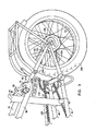
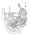
図1、13および15を参照すると、本発明の折りたたみ式自転車10の一実施形態が例示される。本発明のこの実施形態は、コアフレームアセンブリ12を備え、このコアフレームアセンブリは、一本のダウンチューブ20(または好ましくは間隔を空けて分離したダウンチューブ165、170)、シートチューブ25、トップチューブ15およびベアリングチューブ30を備え、ここでそのダウンチューブ20、シートチューブ25、トップチューブ15およびベアリングチューブ30は、互いに実質的に固定した関係にある。そのダウンチューブ165、170は、好ましくは、それらの間にギャップを有し、そのギャップは、フロントホイール175とほぼ同じ幅であるか、またはわずかに広い幅である。そのダウンチューブ165、170は、互いに平行であってもよいし、角度がついていてもよいし、または弯曲していてもよい。あるいは、弯曲を有する一本のダウンチューブが提供されるか、または中間部で分離された一本のチューブが提供され、それが上方向に折りたたまれる場合に、そのフロントホイールを収容する形状にされる。
With reference to FIGS. 1, 13 and 15, one embodiment of a
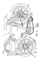
本発明の第2の実施形態は、図2および18に例示される。この実施形態において、2人乗り用折りたたみ式自転車70が提供される。この実施形態は、その単一のシート実施形態10において見出される種々の特徴を備え、ダウンチューブ20または空間的に分離したダウンチューブ165、170のコアフレームアセンブリ、シートチューブ25、トップチューブ15およびベアリングチューブ30を備え、ここでそのダウンチューブ165、170、シートチューブ25、トップチューブ15およびベアリングチューブ30は、実質的に互いに対して固定されている。図2、3および18を参照すると、その2人乗り用折りたたみ式自転車70は、第2のシート40および第2のシートチューブファスナー50とともに、第2のシートチューブ45を備える。好ましくは、その第2のシートチューブファスナー50は、クイックリリースファスナーであるが、ファスナー(例えば、ラッチ、ロック、および適切なナットとボルトの構成)が使用されてもよい。
A second embodiment of the present invention is illustrated in FIGS. In this embodiment, a two-
必要に応じて、1人乗り自転車は、2人乗り用折りたたみ自転車へと、その第2のシートチューブ45を、その上部シートステイ85を備えるその2つの上部シートステイチューブ75、80の間に配置することによって、変換され得る。その上部シートステイ85には、その第2のシートチューブファスナー受容部55が取り付けられ、この受容部は、その第2のシートチューブファスナー50を受容するようなサイズにされる。その第2のシートチューブ45の下端は、その第2のシートチューブ支持体60に対して配置され、図3に示されるように、その2つの前方ボトムブラケットチューブ90、95の間に位置する。この様式で、その折りたたみ式自転車10は、そのフレーム寸法を変化させることも、その自転車ホイールベースを変化させることもなく、2人乗り用折りたたみ式自転車70に変換され得る。
If necessary, the single-seater bicycle is arranged into a two-seater folding bicycle with its
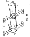
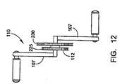
ここで図18を参照すると、その2人乗り用折りたたみ式自転車70は、必要に応じて、中間スプロケットアセンブリ110と連結した第2のペダルアセンブリ107を備え得る。図11および18に示されるように、好ましくはその第2のペダルアセンブリ107は、その第1のペダルアセンブリ100と同じ角度位置において整列される。あるいは、1対のフットレスト(示さず)は、適切で、安全かつ便利な場合、フレームの何れの場所にも(例えば、その2つの前方ボトムブラケットチューブ90、95の上に)取り付けられ得る。
Referring now to FIG. 18, the two-seater
その2人乗り用自転車のさらなる実施形態において、その第2のシート40は、シート40の乗り手が後ろに向き得るように配置される。選択肢的なフットレストは、その後ろに向いている乗り手のシートに快適な休息場所を与えるように提供され得る。同様に、そのシート40は、前に向いているか、または後ろに向いていると、乗り手の快適性を増す背もたれのような快適さが備えられ得る。
In a further embodiment of the two-seater bicycle, the
図4および14を参照すると、本発明の折りたたみ式自転車10は、折りたたまれた構成において例示される。種々の選択肢的な折りたたみ特徴が、その図面に例示されている。図1、4、13および15における例示された実施形態において、その選択肢的な折りたたみ要素は、折りたたみ式フロントフォークアセンブリ115、折りたたみ式リヤホイールアセンブリ120および折りたたみ式ハンドルバーアセンブリ125を備える。さらに、そのシート35は、必要に応じて、シートロック123を解放し、そのシート取り付けチューブ124が、そのシートチューブ25の中へ滑るようにすることによって、シートチューブ25の中へと引っ込められ得る。よって、好ましくは、そのシート取り付けチューブ124は、シートチューブ25の寸法よりも小さな寸法を有し、シート取り付けチューブ124が、シートチューブ25内で動くことを可能にする。
With reference to FIGS. 4 and 14, the
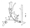
図5および6に示されるように、その折りたたみ式ハンドルバーアセンブリ125は、ベアリングチューブ30(ヘッドチューブともいわれる)と回転可能に連結された、取り付け部材135(グーズネックともいわれる)を備える。そのハンドルバー140は、ハンドルバーピボット軸130の周りにその取り付け部材135に取り付けられる。好ましくは、そのハンドルバー140は、図1、2および5に例示されるような上を向いた位置から、例えば、図3、4および6に示されるような折りたたまれた下向きの位置まで回転され得る。任意の機構が使用され得、そのハンドルバー140が、自転車運転位置で上を向いて、かつ安全なステアリングを可能にするように十分に固定され、その後、解放可能であり、かつ自転車10、70の折りたたまれた構成において、下向きに回転されるようにする。一実施形態において、そのハンドルバーチューブとその取り付け部材135との間の摩擦ばめが存在し、その取り付け部材は、そのハンドルバーチューブを受容するために適した形状にされる。別の実施形態において、ラッチング機構が提供され、別の実施形態においては、ラチェット機構が提供される。そのハンドルバー要素140は、それらのそれぞれの端部でチュービング、およびハンドル142を備え得る。
As shown in FIGS. 5 and 6, the
一実施形態において、そのそれぞれのハンドルバー要素140は、その自転車の折りたたまれたサイズをさらに小さくするために、内側に同様に折りたたまれ得る。この実施形態において、ハンドルバーピボット軸130は、ハンドルバー140とその取り付け部材135の交点で提供される。一実施形態のハンドルバーラッチ145(これは、ハンドルバー要素140を解放する)は、フックアンドループ(hook−and−loop)型であるが、他の型のラッチ(例えば、クイック−リリースラッチ、または任意の他の型の適切なラッチもしくはファスナー)が使用されてもよい。
In one embodiment, the
ここで図6、7および8を参照すると、そのハンドルバーアセンブリ125を折りたたむ好ましい方法は、ここで記載される。好ましくは、そのハンドルバーアセンブリ125全体は(そのフロントホイール175とともに)、そのアセンブリ全体が、後ろ向きの方向にあるように、約180°回転される。この回転を達成するために、その取り付け部材135は、所望される場合、そのベアリングチューブ30内で回転される。この回転力は、フロントホイール175へと、その関連づけられた取り付け要素を介して伝えられる。この最初の回転の後に、次いで、そのハンドルバーラッチ145は解放されて、各ハンドルバーチューブ140が、その関連づけられた要素とともに、それら自体のハンドルバーピボット軸130の周りに回転するようにされる。本発明の一実施形態において、一方のハンドルバーピボット軸130は、45°の角度を付けられ、他方のハンドルバーピボット軸130は、35°の角度を付けられ、そのハンドルバーチューブ140の端部に取り付けられたそのハンドル142が、トップチューブ15の下に折りたたまれた位置にある場合、互いに接触しないようにされる。
Referring now to FIGS. 6, 7 and 8, a preferred method for folding the
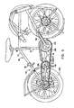
図7および8を参照すると、そのフロントフォークアセンブリ115が例示される。図1に示されるような自転車運転時の構成において、そのフロントフォークアセンブリ115は、そのフロントホイール175を、軸を介してそのフレーム12に装備する。フロントフォークアセンブリ115の要素の任意の配置が使用され得、そのフロントホイール115を回転可能に装備し、必要に応じて、そのフロントホイールが、折りたたみ操作時にそのフレーム12に向かって動くことを可能にすることが認識される。例示された実施形態において、そのフロントフォークアセンブリ115は、そのフレーム12のベアリングチューブ30にピボット可能に取り付けられる。これは、折りたたみ式自転車10が、図1に示されるように、自転車運転時の構成において配置される場合、前方に延びるフロントフォーク150を備える。取り外し可能かつ回転可能に連結されたフロントホイール175を有するスイングアーム155が、フォークピボット軸157の周りに、そのフロントフォーク150にピボット可能に取り付けられる。スターラップラッチ(stirrup latch)180を備えるスターラップ160は、そのスイングアーム155に固定して取り付けられる。そのスイングアーム155およびそのスターラップ160はともに、そのフロントホイール175の周りに配置される。
With reference to FIGS. 7 and 8, the
好ましい実施形態において、そのスターラップラッチ180は、バネロックであるが、他の型のラッチおよびファスナー(例えば、フックアンドループファスナー、またはクイックリリースファスナー)が使用されてもよい。そのフロントフォークアセンブリ115は、そのフロントフォーク150を約180°回転させることによって折りたたまれる。そのスターラップラッチ180は、次いで、解放され、そのスターラップ160を自由にし、図7および8に示されるように、乗り手が、そのスイングアーム155およびスターラップ160を、フォークピボット軸157の周りに回転させるようにする。
In a preferred embodiment, the
折りたたまれた構成の例は、図4および8に例示される。折りたたまれた構成において、そのフロントホイール175は、フレームに向かって動く。これは、好ましくは、そのダウンチューブ20を備える2つのダウンチューブ要素165,170の間に配置される。
An example of a folded configuration is illustrated in FIGS. In the folded configuration, its
別の実施形態のフロントフォークアセンブリ115は、図15、16および17に示されるように、2つのバネまたは衝撃吸収体14を備え得る。これらのバネまたは衝撃吸収体は、フロントフォーク150とそのスターラップ160および/もしくはスイングアーム155のいずれかとの間に取り付けられる。その2つのバネもしくは衝撃吸収体14は、その折りたたみ式自転車10がその運転モードにおいて構成されている場合、そのスターラップラッチ180をその閉じた位置で固定する。そのバネまたは衝撃吸収体14は、任意の型(例えば、エラストマー型、液圧式または空気圧式)であり得る。1以上のバネまたは衝撃吸収体14が、フロントフォークアセンブリ115内のどこの場所でも、任意の適切な位置に取り付けられ得ることが理解される。
Another embodiment of the
その折りたたみ式フロントフォークアセンブリ155の1つの特徴は、ベアリングチューブの「ヘッド角」が、非折りたたみ自転車のヘッド角と同様に構成され得ることである。そのヘッド角は、フロントフォークすくい角を決定し、このフロントフォークすくい角は、ステアリングの「素早さ」に影響を及ぼす。すなわち、本発明のステアリングは、急なフロントフォークすくい角を生じる、より急なヘッド角を有する従来の折りたたみ自転車とは対照的に、非折りたたみ自転車に慣れた乗り手に自然であると感じさせる。これは、比較的素早いステアリングを作り出すために提供され、所望される場合、不安定な、または乱れたステアリングの感触を生じる。
One feature of the folding
任意のリヤホイールアセンブリ120もまた提供される。リヤホイールをフレーム12に対して回転可能に設置するため、および所望されるように1つ以上のシートアセンブリを設置するために適切な任意のアセンブリが、使用され得る。図示される実施形態において、シートステイは、上部シートステイ85および下部シートステイ185に分割される。上部シートステイ85は、必要に応じて、2つの上部シートステイチューブ75、80を有し得る(図3に示される)。下部シートステイ185は、図3、9、および10に示されるように、必要に応じて、2つの下部シートステイチューブ190、195を備える。下部シートステイ185に、シートステイファスナーレシーバー215が取り付けられており、このレシーバーは、シートステイファスナー210を受容するような大きさにされる。この様式で、下部シートステイ185は、上部シートステイ85に取り外し可能に連結される。好ましくは、シートステイファスナー210は、迅速に解放される型であるが、他の適切なファスナーまたはラッチが使用され得る。また、レシーバーに対するファスナーの配置は、切り替えられ得る。
An optional
図3、9、および10に示されるように、本発明の1つの特徴は、底部ブラケットが、前方底部ブラケット(2つの前方底部ブラケットチューブ90、95を備える)と後方底部ブラケット(2つの後方底部ブラケットチューブ200、205を備える)とに分割されることである。これらのチューブは、ピボット220によって旋回可能に接続される。中心スプロケットアセンブリ110が、ピボット220の周りに回転可能に連結される。中心スプロケットアセンブリ110は、前方チェーン225によって前方スプロケット105に接続されており、この前方チェーンは、中心スプロケットアセンブリ110の上で前方スプロケット105から第一の中心スプロケット112へと延びる(図11および12に記載されるとおり)。後方チェーン230は、第二の中心スプロケット114を後方ハブ235に接続し、この後方ハブは、1つ以上のスプロケット237を備え得、異なるギア比を提供する。
As shown in FIGS. 3, 9, and 10, one feature of the present invention is that the bottom bracket comprises a front bottom bracket (comprising two front
好ましい2人乗り用自転車の実施形態において、第一のスプロケット105の直径は、第一の中心スプロケット112の直径と同じであり、そして第二の中心スプロケット114の直径は、後方ハブ235上の1つ以上のスプロケット237の直径より大きいが、ペダルアセンブリ100、107のいずれかにおいて発生したペダルの力をリヤホイール240に伝えることを可能にする、任意のスプロケットサイズが使用され得る。
In the preferred two-seater bicycle embodiment, the diameter of the
本発明の1つの実施形態において、後方ハブ235は、内部ギアを備え得るか、または後方ハブ235は、外部ギアおよび変速装置を備えて、これらのギアの間でチェーンを移動させ得る。さらに、前方スプロケット105は、図示における2つのスプロケット112、114以外に、さらなるスプロケットを備え得る。この様式で、さまざまなギア比が提供され得る。本発明の1つの特徴は、2つのスプロケットアセンブリ105、110が、ほとんどの自転車速度の要件に適切であり得るギア比を提供することである。
In one embodiment of the invention, the
チェーン225および230は、それぞれのスプロケット105、110の間で力を伝達するための機構を提供すると記載されるが、ハブ機構235の力が、乗る人の足または手から適切に駆動されるホイールへと力が適切に伝達されることを可能にする任意の機構を介して伝達され得ることが注目されるべきである。例えば、力は、ペダル100または107から、駆動シャフトを介して、リヤホイール240またはフロントホイール175に伝達され得る。このような駆動シャフトシステムは、広範に公知であり、そして例えば、エンジンから1つ以上のホイールへと推進力を伝達するために、モーター付きの乗り物において使用されている。あるいは、電力供給源65が、推進力を提供するために備えられ得る。電力源65は、電気モーターまたは内燃モーターを備え得、これらは、好ましい実施形態において、折りたたみ可能な自転車10または2人乗り用の折りたたみ可能な自転車70の折りたたまれた寸法を増加させない。
Although the
再度図3、9および10を参照して、リヤホイールアセンブリ120を折りたたむ方法が、記載される。シートステイファスナー210がシートステイファスナーレシーバー215から取り外されると、リヤホイール240が、ピボット220の周りでシート35の方へと回転される。前方チェーン225は、前方スプロケット105と後方スプロケット110との間に位置決めされたままであり、一方で、後方チェーン230は、後方スプロケット110と後方ハブ230との間に位置決めされたままである。2つの後方底部ブラケットチューブ200、205は、リヤホイール240とともに上方に移動する。この構成要素の配置は、折りたたみ式プロセスの間、前方スプロケット105と後方スプロケット110との間の寸法を、実質的に一定に維持して、それぞれのチェーン225、230におけるあらゆるたるみを回避する。従って、折りたたみ可能な自転車10の折りたたみ式および展開の間にチェーン225、230が外れることが不可能である。本発明の代替の実施形態は、チェーンの代わりに、駆動ベルト(好ましくは、ギア付きの駆動ベルト)を使用し得る。
With reference again to FIGS. 3, 9 and 10, a method of folding the
図4に示されるように、完全に折りたたまれると、リヤホイール240は、シート35に隣接して位置決めされる。ロックデバイスが、リヤホイール240を折りたたまれた位置に維持するために使用され得る。これは、折りたたまれた自転車10のサイズを大いに減少させ、この自転車が、大きい鞄、リュックサックにおいて運ばれ、そして小さい乗り物に容易に積み込まれることを可能にする。
As shown in FIG. 4, when fully folded, the
さらに、折りたたみ可能な自転車10または2人乗り用の折りたたみ可能な自転車70の幅を減少させるために、ペダルもまた折りたたまれ得る。さらに、折りたたみ可能な自転車10、または2人乗り用の折りたたみ可能な自転車70は、折りたたまれた寸法を増加させることなく、電気モーターまたは内燃モーターを備えられ得る。
Furthermore, the pedals may also be folded to reduce the width of the
提供されたフレームアセンブリ12を使用してホイールが適切に折りたたまれる、任意の大きさのホイール直径が使用され得る。例えば、フロントホイール175とリヤホイール240との両方が、直径14インチまたは16インチであり得るが、他のホイールサイズ(たとえば、直径23インチまたはほかのサイズなど)が使用され得る。さらに、折りたたみ可能な自転車10および2人乗り用の折りたたみ可能な自転車70は、ブラケット、ライト、フェンダー、キックスタンド、および他の設備を備え得る。さらに、フレームは、小児、または大きい大人に適合するような大きさにされ得るか、あるいは図16に示されるように、女性用自転車に伝統的に提供されるように、トップチューブ15が、ダウンチューブ20により近く位置決めされ得る。
Any size wheel diameter can be used that allows the wheel to be properly folded using the provided
ここで図19から20を参照すると、折りたたみ可能なペダルアセンブリ11が図示されている。ペダルクランク16に、ペダルマウント51が取り付けられている。細いペダル部材52が、ペダルマウント51に連結される。細いペダル部材52またはペダルマウント51のいずれかが、ペダルクランク16の周りで回転し得ることが理解される。外側フットレスト57が、ペダル旋回軸58の周りに旋回可能に連結され、そして折りたたまれた位置にある場合に、図20に示されるように、折りたたみ可能なペダルアセンブリ11の幅をかなり減少させる。展開された位置にある場合に、図19に示されるように、外側フットレスト57は、細いペダル部材52と組み合わせて、運転者の足を受容するためのかなりの面積を提供する。
Referring now to FIGS. 19-20, a
従って、折りたたみ可能な自転車が提供されることがわかる。当業者は、本発明が、上記実施形態以外に実施され得ることを理解し、これらの実施形態は、説明の目的で記載されており、そして限定の目的ではない。本明細書および添付の図面に記載される説明および実施例は、本発明の実施形態を記載するのみである。本明細書および図面は、この特許文献の範囲を排他的に限定するとは意図されない。上記実施形態以外の多くの設計が、添付の特許請求の範囲の文言的範囲および/または法律的範囲内にあり、そして本発明は、特許請求の範囲によってのみ限定される。本明細書において議論された特定の実施形態に対する種々の均等物が、同様に、本発明を実施し得ることが、注目される。 Thus, it can be seen that a foldable bicycle is provided. Those skilled in the art will appreciate that the present invention may be practiced other than as described above, which have been described for purposes of illustration and not limitation. The description and examples set forth in this specification and the accompanying drawings only describe embodiments of the invention. The specification and drawings are not intended to limit the scope of this patent document exclusively. Many designs other than the above embodiments are within the wording and / or legal scope of the appended claims, and the present invention is limited only by the claims. It is noted that various equivalents to the specific embodiments discussed herein can similarly practice the invention.
10 折りたたみ式自転車10 Folding bicycle
12 コアフレームアセンブリ12 Core frame assembly
15 トップチューブ15 Top tube
20 ダウンチューブ20 Down tube
25 シートチューブ25 seat tube
30 ベアリングチューブ30 Bearing tube
Claims (1)
ダウンチューブ;
シートチューブ;
トップチューブ;および
ベアリングチューブ、
を備え、該ダウンチューブ、シートチューブ、トップチューブおよびベアリングチューブは、互いに対して実質的に固定されている、折りたたみ式自転車。 A folding bicycles, the following:
Down tube;
Seat tube;
The top tube; and bearing tube,
And the down tube, seat tube, top tube and bearing tube are substantially fixed relative to each other.
Applications Claiming Priority (6)
| Application Number | Priority Date | Filing Date | Title |
|---|---|---|---|
| SI200200308A SI21365A (en) | 2002-12-18 | 2002-12-18 | Folding bicycle |
| SIP-200200308 | 2002-12-18 | ||
| PCT/IB2003/001243 WO2003086848A1 (en) | 2002-04-15 | 2003-03-03 | Folding bicycle |
| IBPCT/IB03/01243 | 2003-03-03 | ||
| US10/461,017 | 2003-06-12 | ||
| US10/461,017 US7229089B2 (en) | 2002-04-15 | 2003-06-12 | Folding bicycle |
Related Parent Applications (1)
| Application Number | Title | Priority Date | Filing Date |
|---|---|---|---|
| JP2005502443A Division JP4658804B2 (en) | 2002-12-18 | 2003-12-12 | folding bicycle |
Related Child Applications (1)
| Application Number | Title | Priority Date | Filing Date |
|---|---|---|---|
| JP2012000635A Division JP2012091788A (en) | 2002-12-18 | 2012-01-05 | Foldable bicycle |
Publications (3)
| Publication Number | Publication Date |
|---|---|
| JP2010001018A true JP2010001018A (en) | 2010-01-07 |
| JP2010001018A5 JP2010001018A5 (en) | 2011-08-04 |
| JP5032537B2 JP5032537B2 (en) | 2012-09-26 |
Family
ID=41583081
Family Applications (3)
| Application Number | Title | Priority Date | Filing Date |
|---|---|---|---|
| JP2005502443A Expired - Fee Related JP4658804B2 (en) | 2002-12-18 | 2003-12-12 | folding bicycle |
| JP2009192630A Expired - Fee Related JP5032537B2 (en) | 2002-12-18 | 2009-08-21 | folding bicycle |
| JP2012000635A Pending JP2012091788A (en) | 2002-12-18 | 2012-01-05 | Foldable bicycle |
Family Applications Before (1)
| Application Number | Title | Priority Date | Filing Date |
|---|---|---|---|
| JP2005502443A Expired - Fee Related JP4658804B2 (en) | 2002-12-18 | 2003-12-12 | folding bicycle |
Family Applications After (1)
| Application Number | Title | Priority Date | Filing Date |
|---|---|---|---|
| JP2012000635A Pending JP2012091788A (en) | 2002-12-18 | 2012-01-05 | Foldable bicycle |
Country Status (26)
| Country | Link |
|---|---|
| EP (2) | EP1575823B1 (en) |
| JP (3) | JP4658804B2 (en) |
| KR (1) | KR100920263B1 (en) |
| CN (1) | CN100408418C (en) |
| AT (1) | ATE422462T1 (en) |
| AU (1) | AU2003296681B2 (en) |
| BR (1) | BR0317515A (en) |
| CA (1) | CA2509674C (en) |
| CU (1) | CU23457A3 (en) |
| DK (1) | DK1575823T3 (en) |
| EA (1) | EA008234B1 (en) |
| EG (1) | EG24492A (en) |
| ES (1) | ES2320653T3 (en) |
| GE (1) | GEP20084389B (en) |
| HK (1) | HK1087387A1 (en) |
| HR (1) | HRP20050752B1 (en) |
| IL (1) | IL169079A (en) |
| MX (1) | MXPA05006542A (en) |
| NO (1) | NO325574B1 (en) |
| NZ (1) | NZ540687A (en) |
| PL (1) | PL209380B1 (en) |
| RS (1) | RS51765B (en) |
| SI (1) | SI1575823T1 (en) |
| UA (1) | UA87451C2 (en) |
| WO (1) | WO2004054871A2 (en) |
| ZA (1) | ZA200504680B (en) |
Cited By (1)
| Publication number | Priority date | Publication date | Assignee | Title |
|---|---|---|---|---|
| JP2012153353A (en) * | 2011-01-27 | 2012-08-16 | Toshio Suzuki | Bicycle with sprockets installed at three locations |
Families Citing this family (8)
| Publication number | Priority date | Publication date | Assignee | Title |
|---|---|---|---|---|
| DE102007037648B4 (en) | 2007-08-09 | 2010-11-25 | Topeak, Inc. | Folding |
| DE102010042570B4 (en) | 2010-10-18 | 2012-07-26 | Jörg Funke | Folding and partially dismountable bicycle |
| HU4497U (en) | 2011-07-22 | 2015-01-28 | Gábor Gerencsér | Foldable bicycle |
| DE102012203859B3 (en) * | 2012-03-13 | 2013-09-19 | Markus Hartmann | Folding |
| TWI592326B (en) * | 2016-03-01 | 2017-07-21 | 洪銚亨 | Folding bicycles, and folding structures and for the folding bicycles |
| EP3587231B1 (en) | 2017-02-24 | 2021-11-17 | Aruanã Energia S/A | Improvements to a folding elliptical bicycle |
| US11084551B1 (en) | 2020-04-22 | 2021-08-10 | Peter Stull | Foldable recumbent tricycle frame |
| IT202000014527A1 (en) * | 2020-06-17 | 2021-12-17 | Rosario Cuda | BICYCLE TRANSMISSION |
Citations (8)
| Publication number | Priority date | Publication date | Assignee | Title |
|---|---|---|---|---|
| JPS5225342A (en) * | 1975-08-15 | 1977-02-25 | Taku Sasagawa | Foldable bicycle for reducing width to half |
| JPS57205284A (en) * | 1981-06-08 | 1982-12-16 | Kikushirou Hashimoto | Folding type bicycle |
| JPS628894U (en) * | 1985-07-02 | 1987-01-20 | ||
| JPH01175587A (en) * | 1987-12-28 | 1989-07-12 | Giorgi Gianfranco | Foldable bicycle |
| JPH01237277A (en) * | 1988-03-18 | 1989-09-21 | Seiichi Ogawa | Bicycle |
| JPH0699871A (en) * | 1992-09-17 | 1994-04-12 | Fuji Heavy Ind Ltd | Portable bicycle |
| JPH09207858A (en) * | 1996-02-05 | 1997-08-12 | Matsushita Electric Ind Co Ltd | Bicycle |
| GB2373770A (en) * | 2001-03-30 | 2002-10-02 | Atb Sales Ltd | Folding bicycle |
Family Cites Families (13)
| Publication number | Priority date | Publication date | Assignee | Title |
|---|---|---|---|---|
| GB526773A (en) * | 1939-03-31 | 1940-09-25 | Andre Jules Marcelin | Improvements in or relating to velocipedes |
| FR1011990A (en) * | 1949-05-11 | 1952-07-02 | Folding bicycle | |
| US3710883A (en) * | 1971-10-22 | 1973-01-16 | P Rizzo | Folding motorcycle or the like |
| US4029326A (en) * | 1976-01-21 | 1977-06-14 | Blow Jr James H | Bicycle construction |
| US4433852A (en) * | 1981-02-12 | 1984-02-28 | Hon Corporation | Foldable and portable vehicle |
| JPS59169286U (en) * | 1983-04-27 | 1984-11-13 | 山村 茂 | Folding bike |
| CN2050024U (en) * | 1988-07-04 | 1989-12-27 | 张汉清 | Portable bicycle |
| JPH0358882U (en) * | 1989-10-16 | 1991-06-10 | ||
| DE4313832A1 (en) * | 1993-04-28 | 1994-11-03 | Markus Riese | Foldable bicycle frame |
| JPH10119866A (en) * | 1996-10-21 | 1998-05-12 | Kikuo Kondou | Folding type handle for bicycle |
| CN2352431Y (en) * | 1998-09-30 | 1999-12-08 | 刘尚明 | Portable bicycle |
| EA008789B1 (en) * | 2002-04-15 | 2007-08-31 | Студио Модерна Са | Folding bicycle |
| KR100650947B1 (en) * | 2004-04-14 | 2006-11-29 | 주식회사 이지업 | A multi-function bicycle |
-
2003
- 2003-12-12 BR BR0317515-4A patent/BR0317515A/en not_active IP Right Cessation
- 2003-12-12 PL PL378031A patent/PL209380B1/en unknown
- 2003-12-12 EA EA200500992A patent/EA008234B1/en not_active IP Right Cessation
- 2003-12-12 CA CA2509674A patent/CA2509674C/en not_active Expired - Fee Related
- 2003-12-12 NZ NZ540687A patent/NZ540687A/en not_active IP Right Cessation
- 2003-12-12 ES ES03813142T patent/ES2320653T3/en not_active Expired - Lifetime
- 2003-12-12 RS YU20050706A patent/RS51765B/en unknown
- 2003-12-12 UA UAA200507051A patent/UA87451C2/en unknown
- 2003-12-12 MX MXPA05006542A patent/MXPA05006542A/en active IP Right Grant
- 2003-12-12 CN CNB200380106924XA patent/CN100408418C/en not_active Expired - Fee Related
- 2003-12-12 GE GEAP20038902A patent/GEP20084389B/en unknown
- 2003-12-12 AU AU2003296681A patent/AU2003296681B2/en not_active Ceased
- 2003-12-12 WO PCT/EP2003/014564 patent/WO2004054871A2/en active IP Right Grant
- 2003-12-12 JP JP2005502443A patent/JP4658804B2/en not_active Expired - Fee Related
- 2003-12-12 DK DK03813142T patent/DK1575823T3/en active
- 2003-12-12 EP EP03813142A patent/EP1575823B1/en not_active Expired - Lifetime
- 2003-12-12 EP EP09152489A patent/EP2060480A3/en not_active Withdrawn
- 2003-12-12 AT AT03813142T patent/ATE422462T1/en not_active IP Right Cessation
- 2003-12-12 SI SI200331573T patent/SI1575823T1/en unknown
-
2005
- 2005-06-08 ZA ZA200504680A patent/ZA200504680B/en unknown
- 2005-06-08 IL IL169079A patent/IL169079A/en not_active IP Right Cessation
- 2005-06-13 NO NO20052869A patent/NO325574B1/en not_active IP Right Cessation
- 2005-06-17 KR KR1020057011259A patent/KR100920263B1/en not_active IP Right Cessation
- 2005-06-18 EG EGNA2005000314 patent/EG24492A/en active
- 2005-06-20 CU CU20050121A patent/CU23457A3/en not_active IP Right Cessation
- 2005-08-30 HR HRP20050752AA patent/HRP20050752B1/en not_active IP Right Cessation
-
2006
- 2006-08-22 HK HK06109322A patent/HK1087387A1/en not_active IP Right Cessation
-
2009
- 2009-08-21 JP JP2009192630A patent/JP5032537B2/en not_active Expired - Fee Related
-
2012
- 2012-01-05 JP JP2012000635A patent/JP2012091788A/en active Pending
Patent Citations (8)
| Publication number | Priority date | Publication date | Assignee | Title |
|---|---|---|---|---|
| JPS5225342A (en) * | 1975-08-15 | 1977-02-25 | Taku Sasagawa | Foldable bicycle for reducing width to half |
| JPS57205284A (en) * | 1981-06-08 | 1982-12-16 | Kikushirou Hashimoto | Folding type bicycle |
| JPS628894U (en) * | 1985-07-02 | 1987-01-20 | ||
| JPH01175587A (en) * | 1987-12-28 | 1989-07-12 | Giorgi Gianfranco | Foldable bicycle |
| JPH01237277A (en) * | 1988-03-18 | 1989-09-21 | Seiichi Ogawa | Bicycle |
| JPH0699871A (en) * | 1992-09-17 | 1994-04-12 | Fuji Heavy Ind Ltd | Portable bicycle |
| JPH09207858A (en) * | 1996-02-05 | 1997-08-12 | Matsushita Electric Ind Co Ltd | Bicycle |
| GB2373770A (en) * | 2001-03-30 | 2002-10-02 | Atb Sales Ltd | Folding bicycle |
Cited By (1)
| Publication number | Priority date | Publication date | Assignee | Title |
|---|---|---|---|---|
| JP2012153353A (en) * | 2011-01-27 | 2012-08-16 | Toshio Suzuki | Bicycle with sprockets installed at three locations |
Also Published As
Similar Documents
| Publication | Publication Date | Title |
|---|---|---|
| US7229089B2 (en) | Folding bicycle | |
| JP5032537B2 (en) | folding bicycle | |
| US6953203B2 (en) | Human powered vehicle | |
| US7249779B2 (en) | Convertible stroller/tricycle | |
| US20050001404A1 (en) | Folding bicycle apparatus and method | |
| JP2006511397A5 (en) | ||
| EP1638835B1 (en) | Folding bicycle apparatus and method | |
| RU1782856C (en) | Bio-vehicle |
Legal Events
| Date | Code | Title | Description |
|---|---|---|---|
| A521 | Request for written amendment filed |
Free format text: JAPANESE INTERMEDIATE CODE: A523 Effective date: 20100816 |
|
| A521 | Request for written amendment filed |
Free format text: JAPANESE INTERMEDIATE CODE: A523 Effective date: 20110622 |
|
| A977 | Report on retrieval |
Free format text: JAPANESE INTERMEDIATE CODE: A971007 Effective date: 20110930 |
|
| A131 | Notification of reasons for refusal |
Free format text: JAPANESE INTERMEDIATE CODE: A131 Effective date: 20111005 |
|
| A521 | Request for written amendment filed |
Free format text: JAPANESE INTERMEDIATE CODE: A523 Effective date: 20120105 |
|
| TRDD | Decision of grant or rejection written | ||
| A01 | Written decision to grant a patent or to grant a registration (utility model) |
Free format text: JAPANESE INTERMEDIATE CODE: A01 Effective date: 20120605 |
|
| A01 | Written decision to grant a patent or to grant a registration (utility model) |
Free format text: JAPANESE INTERMEDIATE CODE: A01 |
|
| A61 | First payment of annual fees (during grant procedure) |
Free format text: JAPANESE INTERMEDIATE CODE: A61 Effective date: 20120628 |
|
| R150 | Certificate of patent or registration of utility model |
Free format text: JAPANESE INTERMEDIATE CODE: R150 |
|
| FPAY | Renewal fee payment (event date is renewal date of database) |
Free format text: PAYMENT UNTIL: 20150706 Year of fee payment: 3 |
|
| LAPS | Cancellation because of no payment of annual fees |