JP2010000335A - Ultrasonic therapeutic devices - Google Patents
Ultrasonic therapeutic devices Download PDFInfo
- Publication number
- JP2010000335A JP2010000335A JP2009018560A JP2009018560A JP2010000335A JP 2010000335 A JP2010000335 A JP 2010000335A JP 2009018560 A JP2009018560 A JP 2009018560A JP 2009018560 A JP2009018560 A JP 2009018560A JP 2010000335 A JP2010000335 A JP 2010000335A
- Authority
- JP
- Japan
- Prior art keywords
- treatment
- main body
- ultrasonic
- transmission member
- longitudinal axis
- Prior art date
- Legal status (The legal status is an assumption and is not a legal conclusion. Google has not performed a legal analysis and makes no representation as to the accuracy of the status listed.)
- Granted
Links
Images


Classifications
-
- A—HUMAN NECESSITIES
- A61—MEDICAL OR VETERINARY SCIENCE; HYGIENE
- A61B—DIAGNOSIS; SURGERY; IDENTIFICATION
- A61B17/00—Surgical instruments, devices or methods, e.g. tourniquets
- A61B17/32—Surgical cutting instruments
- A61B17/320068—Surgical cutting instruments using mechanical vibrations, e.g. ultrasonic
-
- A—HUMAN NECESSITIES
- A61—MEDICAL OR VETERINARY SCIENCE; HYGIENE
- A61B—DIAGNOSIS; SURGERY; IDENTIFICATION
- A61B17/00—Surgical instruments, devices or methods, e.g. tourniquets
- A61B17/32—Surgical cutting instruments
- A61B17/320016—Endoscopic cutting instruments, e.g. arthroscopes, resectoscopes
-
- A—HUMAN NECESSITIES
- A61—MEDICAL OR VETERINARY SCIENCE; HYGIENE
- A61B—DIAGNOSIS; SURGERY; IDENTIFICATION
- A61B17/00—Surgical instruments, devices or methods, e.g. tourniquets
- A61B17/32—Surgical cutting instruments
- A61B17/3205—Excision instruments
- A61B17/32056—Surgical snare instruments
-
- A—HUMAN NECESSITIES
- A61—MEDICAL OR VETERINARY SCIENCE; HYGIENE
- A61B—DIAGNOSIS; SURGERY; IDENTIFICATION
- A61B17/00—Surgical instruments, devices or methods, e.g. tourniquets
- A61B17/32—Surgical cutting instruments
- A61B17/3205—Excision instruments
- A61B17/3207—Atherectomy devices working by cutting or abrading; Similar devices specially adapted for non-vascular obstructions
-
- A—HUMAN NECESSITIES
- A61—MEDICAL OR VETERINARY SCIENCE; HYGIENE
- A61B—DIAGNOSIS; SURGERY; IDENTIFICATION
- A61B17/00—Surgical instruments, devices or methods, e.g. tourniquets
- A61B17/32—Surgical cutting instruments
- A61B17/320068—Surgical cutting instruments using mechanical vibrations, e.g. ultrasonic
- A61B2017/320089—Surgical cutting instruments using mechanical vibrations, e.g. ultrasonic node location
-
- A—HUMAN NECESSITIES
- A61—MEDICAL OR VETERINARY SCIENCE; HYGIENE
- A61B—DIAGNOSIS; SURGERY; IDENTIFICATION
- A61B17/00—Surgical instruments, devices or methods, e.g. tourniquets
- A61B17/32—Surgical cutting instruments
- A61B17/320068—Surgical cutting instruments using mechanical vibrations, e.g. ultrasonic
- A61B17/320092—Surgical cutting instruments using mechanical vibrations, e.g. ultrasonic with additional movable means for clamping or cutting tissue, e.g. with a pivoting jaw
- A61B2017/320093—Surgical cutting instruments using mechanical vibrations, e.g. ultrasonic with additional movable means for clamping or cutting tissue, e.g. with a pivoting jaw additional movable means performing cutting operation
Abstract
Description
本発明は、骨などを処置する整形外科用の超音波処置具に関する。 The present invention relates to an orthopedic ultrasonic treatment instrument for treating bones and the like.
一般に整形外科手術における骨や軟骨などの硬組織が切除または切削される場合、機器が用いられる。この機器は、例えばコールドナイフ、手動式のパンチ鉗子、電動モータによって駆動するシェーバー、ドリルである。 In general, an instrument is used when a hard tissue such as bone or cartilage in an orthopedic surgery is excised or cut. This apparatus is, for example, a cold knife, a manual punch forceps, a shaver driven by an electric motor, or a drill.
例えば特許文献1には、超音波ハンドピースとこれに使用する超音波ホーンが開示されている。超音波ホーンは、超音波ハンドピースの構成部材である。超音波ホーンは、少なくとも1以上の面部からなる作業部と、作業部により微細に破砕された骨組織を掻き取るためのエッジ部とを有している。超音波ハンドピースと超音波ホーンとは、硬組織の切削に使用する超音波ハンドピースにおいて、メス部の被切削部位へに過刺に起因する種々の弊害を防止して、広い視野の下にメス部の動きを精妙にコントロールし治療目的に則した正確な骨などの硬組織の切削を実現する。 For example, Patent Document 1 discloses an ultrasonic handpiece and an ultrasonic horn used therefor. The ultrasonic horn is a constituent member of an ultrasonic handpiece. The ultrasonic horn has a working part composed of at least one surface part and an edge part for scraping off bone tissue finely crushed by the working part. Ultrasonic handpiece and ultrasonic horn are an ultrasonic handpiece used for cutting hard tissue. Accurately control the movement of the female part and realize accurate cutting of hard tissues such as bone according to the purpose of treatment.
一般的に、上述した機器による硬組織(処置対象部位)の処置(切除または切削)では、繊細な処置が困難であり、硬組織の周囲の軟組織を巻き込んでしまうために、意図しない損傷が生じてしまう。 In general, in the treatment (resection or cutting) of the hard tissue (treatment target site) with the above-described device, it is difficult to perform a delicate treatment, and the soft tissue surrounding the hard tissue is involved, and unintended damage occurs. End up.
そのため本発明は、上記課題を鑑みて、処置対象部位を容易且つ繊細に処置することができ、軟組織を巻き込むことなく処置でき、意図しない損傷を生じさせることなく処置できる超音波処置具を提供することを目的とする。 Therefore, in view of the above problems, the present invention provides an ultrasonic treatment instrument that can easily and delicately treat a site to be treated, can be treated without involving soft tissue, and can be treated without causing unintended damage. For the purpose.
本発明は、超音波振動を発生する超音波振動子ユニットと、前記超音波振動子ユニットと基端側にて接続し、前記超音波振動子ユニットにて発生した超音波振動を基端側から先端側に伝達する伝達部材と、前記伝達部材が挿通されるシースと、前記シースの先端から突出するように前記伝達部材の先端に配設され、前記伝達部材から伝達される超音波振動によって処置対象部位を処置する処置部と、前記処置部に配設され、前記処置対象部位を処置する処置部本体部と、前記シースの先端から突出するように前記シースの中に配設され、前記処置対象部位を処置する処置部材と、前記処置部材の先端に配設され、前記処置対象部位を処置する処置部材本体部と、を具備し、前記処置部材本体部が前記処置部本体部と重なることで、前記処置部材本体部と前記処置部本体部とは前記処置対象部位を処置する超音波処置具を提供する。 The present invention relates to an ultrasonic transducer unit that generates ultrasonic vibrations, and is connected to the ultrasonic transducer unit at the proximal end side, and the ultrasonic vibrations generated by the ultrasonic transducer unit from the proximal end side. A transmission member that transmits to the distal end side, a sheath through which the transmission member is inserted, a treatment by ultrasonic vibration that is disposed at the distal end of the transmission member so as to protrude from the distal end of the sheath, and is transmitted from the transmission member A treatment section that treats a target site; a treatment section body that is disposed in the treatment section and treats the treatment target site; and is disposed in the sheath so as to protrude from a distal end of the sheath; A treatment member that treats a target site; and a treatment member main body that is disposed at a distal end of the treatment member and treats the treatment target site; and the treatment member main body overlaps the treatment portion main body In the treatment section The said treatment portion body portion and the body portion to provide an ultrasonic treatment instrument for treating the surgical target portion.
本発明によれば、処置対象部位を容易且つ繊細に処置することができ、軟組織を巻き込むことなく処置でき、意図しない損傷を生じさせることなく処置できる超音波処置具を提供することができる。 According to the present invention, it is possible to provide an ultrasonic treatment tool that can easily and delicately treat a site to be treated, can be treated without involving soft tissue, and can be treated without causing unintended damage.
以下、図面を参照して本発明の実施形態について詳細に説明する。
図1から図5を参照し、第1の実施形態について説明する。
図1に示すように整形外科用の超音波処置具1は、例えば整形外科手術における処置対象部位を処置する。処置対象部位とは、例えば骨や軟骨などの硬組織等である。処置とは、例えば切除や切削などである。
Hereinafter, embodiments of the present invention will be described in detail with reference to the drawings.
The first embodiment will be described with reference to FIGS. 1 to 5.
As shown in FIG. 1, an orthopedic ultrasonic treatment instrument 1 treats a treatment target site in, for example, orthopedic surgery. The treatment target site is, for example, a hard tissue such as bone or cartilage. The treatment is, for example, excision or cutting.
超音波処置具1は、超音波処置具1の基端側に配設される略円筒形状のケース11と、ケース11の先端側に配設されているシース20とを有している。
The ultrasonic treatment instrument 1 includes a substantially
ケース11の基端側には、出力用接続ケーブル2が接続している。ケース11は、出力用接続ケーブル2を通じて図示しない超音波振動駆動装置と接続している。
The output connection cable 2 is connected to the base end side of the
図1と図2とに示すようにケース11には、超音波振動子ユニット12がケース11の内部に固定されている。超音波振動子ユニット12は、超音波振動を発生する圧電素子と、ケース11の長手軸方向において、超音波振動子ユニット12の先端側に配設され、超音波振動を増幅するホーン12aとを有している。
As shown in FIGS. 1 and 2, the
超音波振動子ユニット12は、電力を超音波振動に変換する部材である。この電力は、図示しない超音波振動駆動装置にて発生し、超音波振動駆動装置から出力用接続ケーブル2を通じて超音波振動子ユニット12に供給され、超音波振動に変換される。
The
超音波振動子ユニット12は、例えばボルト締めのランジュバン型振動子(Bolt−clamped Langevin type Transducer(BLT))である。
The
ホーン12aは、例えばチタンやジュラルミンやステンレス等の金属材料である。
The
ホーン12aの先端には、プローブ30がシース20を挿通するように取り付けられている。プローブ30は、ホーン12aで増幅された超音波振動を超音波処置具1の先端側に伝達する伝達部材である。プローブ30は、ホーン12aに対して例えばネジなどによって着脱自在に締結(固定)されている。つまりプローブ30は、プローブ30の基端側にてホーン12aを介して超音波振動子ユニット12と接続し、超音波振動子ユニット12にて発生した超音波振動をプローブ30の基端側からプローブ30の先端側(超音波処置具1の先端側)に伝達することとなる。
A
プローブ30は、例えばチタンやジュラルミンやステンレス等の金属材料である。
The
プローブ30は、プローブ30の基端側に、超音波振動子ユニット12(ホーン12a)から伝達される超音波振動をさらに増幅するホーン30dを有している。
The
プローブ30の先端には、処置部31がシース20の先端から突出するように配設されている。処置部31は、超音波振動子ユニット12にて発生しプローブ30から伝達される超音波振動によって処置対象部位を処置する。処置部31は、略平板形状を有している。処置部31は、処置対象部位と接触することで、超音波振動によって処置対象部位を処置する。
A
またプローブ30は、超音波振動の腹位置において、プローブ30をシース20内に固定するための支持部材(ゴムライニング)30eを有している。支持部材30eは、例えばシリコンゴムなどの樹脂である。
The
また処置部31は、ケース11の長手軸方向(プローブ30の長手軸方向)に長径なループ形状を有している。そのため処置部31には、処置部31の厚み方向に貫通している開口部31aが形成されている。プローブ30の長手軸方向における開口部31aの先端側には、後述する外刃21aと共に処置対象部位をせん断するせん断エッジ31b(図4参照)がプローブ30の長手軸方向に対して所望に傾いて形成されている。せん断エッジ31bは、ループ内のプローブ30の長手軸方向の先端側にて、プローブ30の長手軸方向に対して所望に傾いて配設されている。言い換えると、せん断エッジ31bは、処置部31の一方の面(例えば上面31c)から他方の面(例えば下面31d)に向けて所望に傾いて配設されている。せん断エッジ31bは、後述する外刃21aと共に処置対象部位をせん断により処置する処置部本体部であり、せん断部である。
The
またシース20には、超音波処置具1を把持するための把持部(グリップ)13が配設されている。把持部13は、弾性力を有している。把持部13は、処置部31を含むプローブ30に対して後述するせん断部材21を、プローブ30の長手軸方向に沿ってスライド(摺動)させる操作部でもある。
The
またケース11には、上述したようにプローブ30が挿通されるシース20がケース11の先端側において配設されている。言い換えるとシース20は、プローブ30を覆っていることとなる。
Further, in the
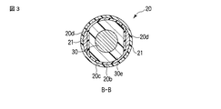
シース20は、図1乃至図3に示すように支持部材30eを覆う内側チューブ20bと、内側チューブ20bを覆う外側チューブ20cとを有している。
The
内側チューブ20bと外側チューブ20cとは、例えばステンレス等の金属材料である。
The
図3に示すように外側チューブ20cは略円筒形状を有しており、内側チューブ20bは非円形筒形状を有している。そのため外側チューブ20cと内側チューブ20bと間には、空間部20dが形成される。空間部20dは、シース20の長手軸方向に沿って配設されている。この空間部20dには、せん断部材21が配設されている。せん断部材21の基端は、図1に示すように把持部13と連結している。またせん断部材21の先端は、図1と図2に示すように処置部31と同様にシース20の先端から突出しており、金属製の外刃21aを有している。つまりせん断部材21は、シース20の先端から突出するようにシース20の中に配設され、処置対象部位をせん断するせん断部材である。言い換えると、せん断部材21は、処置対象部位をせん断により処置する処置部材である。また外刃21aは、せん断エッジ31bと共に処置対象部位をせん断により処置する処置部材本体部となる。
As shown in FIG. 3, the
せん断部材21は、把持部13の操作によって、プローブ30の長手軸方向に沿って処置部31を含むプローブ30に対してスライド可能である。把持部13の操作とは、把持部13が術者によって握られたり、握りを離されることである。つまりせん断部材21は、把持部13の操作によって、処置部31を含むプローブ30に対して、シース20の長手方向に沿って、シース20内(外側チューブ20cと内側チューブ20bとの間、つまり空間部20d内)をスライド可能な形状を有している。そのためせん断部材21の形状は、空間部20dの形状と同一である必要はない。
The shearing
せん断部材21がシース20の長手方向に沿って処置部31を含むプローブ30に対してスライドする際、外刃21aは、図5に示すように処置部31(上面31cと下面31d)をスライドし、せん断エッジ31bまでに移動することとなる。そのとき外刃21aがせん断エッジ31bと重なることで、外刃21aとせん断エッジ31bとは処置対象部位をせん断する。
When the shearing
次に本実施形態における動作方法について説明する。
処置部31が生体組織の処置対象部位に接触する。この状態で図示しない超音波振動駆動装置にて発生した電力は、図示しない超音波振動駆動装置から出力用接続ケーブル2を通じて超音波振動子ユニット12に供給され、超音波振動子ユニット12によって超音波振動に変換される。超音波振動は、ホーン12aによって増幅され、プローブ30に伝達される。このとき超音波振動は、ホーン30dによってさらに増幅され、プローブ30から処置部31を通じて処置対象部位に伝達される。つまり超音波振動は、プローブ30の基端側から先端側に伝達される。これにより処置対象部位は、処置部31にて超音波振動によって処置される。
Next, an operation method according to this embodiment will be described.
The
また把持部13が術者によって握られると、せん断部材21がプローブ30の長手軸方向に沿って処置部31の先端側に向かってスライドする。これにより外刃21aは処置部31(上面31cと下面31d)をスライドし、せん断エッジ31bまでに移動することとなる。そのとき外刃21aがせん断エッジ31bと重なり、処置対象部位は、外刃21aと超音波振動しているせん断エッジ31bとによってせん断される。
When the grasping
また把持部13が術者によって握りを離されると、把持部13は、把持部13が有する弾性力によって、把持部13が術者によって握られる前の状態に戻る。これによりせん断部材21がプローブ30の長手軸方向に沿ってシース20の先端側に向かってスライドする。
When the grasping
このように本実施形態では、超音波振動によって処置部31にて処置対象部位を容易に処置することができる。また本実施形態では、把持部13を把持することによって、せん断部材21をスライドさせることができ、外刃21aと超音波振動しているせん断エッジ31bとによって処置対象部位をせん断することができる。これにより本実施形態では、処置対象部位を容易且つ繊細に処置することができ、軟組織を巻き込むことなく処置でき、意図しない損傷を生じさせることなく処置できる。
Thus, in this embodiment, the treatment target site can be easily treated by the
また本実施形態では、開口部31a内に処置対象部位を配置することで、超音波振動によって容易に切削等の処置を行うことができる。
Moreover, in this embodiment, treatment, such as cutting, can be easily performed by ultrasonic vibration by disposing the treatment target portion in the
このように本実施形態では、超音波振動による切削とせん断との2種類の処置方法を提供することができる。 Thus, in this embodiment, two types of treatment methods, cutting and shearing by ultrasonic vibration, can be provided.
また本実施形態では、せん断エッジ31bにおける超音波振動により処置対象部位のせん断面を滑らかにすることができ、術後における患者の痛みをやわらげることができる。
Moreover, in this embodiment, the shear surface of a treatment object site | part can be smoothed by the ultrasonic vibration in the
また本実施形態では、せん断部材21をスライドさせて処置対象部位を処置できるために、軟組織を巻き込むことなく処置でき、意図しない損傷を生じさせることなく処置できる(処置対象部位を損傷することを防止することができる)。
In the present embodiment, since the treatment target region can be treated by sliding the shearing
また本実施形態では、把持部13を把持することで、処置対象部位をせん断することができるために、せん断のための操作が容易である。
Moreover, in this embodiment, since the treatment target site can be sheared by grasping the grasping
なおせん断エッジ31bは、図4に示す形状に限定する必要はない。
The
例えば図6Aに示すようにせん断エッジ31bは、処置部31の上面31cからプローブ30の長手軸方向にむけて斜めに、また処置部31の下面31dからプローブ30の長手軸方向にむけて斜めに形成されていても良い。
For example, as shown in FIG. 6A, the
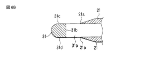
また図6Bに示すように、せん断エッジ31bは、処置部31の上面31cから下面31dに向けて、プローブ30の長手軸方向に対して略垂直に配設されていても良い。
As shown in FIG. 6B, the
次に本発明に係る第2の実施形態について図7と図8を参照して説明する。なお上述した第1の実施形態とその変形例との同一の構成については第1の実施形態と同一の参照符号を付すことにより説明を省略する。
本実施形態の処置部33は、開口部31aを有しておらず、プローブ30の長手軸方向に対して略垂直方向に起上している突起部33aを一体的に有している。つまり突起部33aを含む処置部33は、鉤形状を有している。突起部33aは、上述した略垂直方向における突起部33aの先端にせん断エッジ31bと同様のせん断部であるせん断エッジ33b(処置部本体部)を有している。突起部33aは、上述した略垂直方向において、せん断エッジ33bが外刃21aと重なる所望な高さを有している。
Next, a second embodiment according to the present invention will be described with reference to FIGS. In addition, about the same structure of 1st Embodiment mentioned above and its modification, description is abbreviate | omitted by attaching | subjecting the same referential mark as 1st Embodiment.
The
処置部33が処置対象部位を処置する際、処置部33はシース20の先端から突出した状態で、処置部33を含む超音波処置具1全体が移動する。処置部33は、突起部33aを処置対象部位に接触させることで、超音波振動によって処置対象部位を処置する。
When the
また把持部13が術者によって握られると、図8に示すようにせん断部材21がプローブ30の長手軸方向に沿って突起部33aに向かってスライドする。これにより外刃21aはせん断エッジ33bに向かって移動することとなる。そのとき外刃21aがせん断エッジ33bと重なることで、処置対象部位は外刃21aとせん断エッジ33bによって切断または処置される。
Further, when the grasping
このように本実施形態では、第1の実施形態と同様の効果を得ることができる。 Thus, in this embodiment, the same effect as that of the first embodiment can be obtained.
また本実施形態の処置部33は鉤形状を有している。そのため本実施形態では、処置部33を容易に処置対象部位に引っ掛けることができ、処置をまでの動作を簡略化することができる。
Moreover, the
次に本発明に係る第3の実施形態について図9乃至と図13を参照して説明する。なお上述した第1の実施形態とその変形例との同一の構成については第1の実施形態と同一の参照符号を付すことにより説明を省略する。
本実施形態の超音波処置具1は、操作部40が回動操作された際に、操作部40の回動操作に応じて、処置部42に対して回動する切断部材44を有している。切断部材44は、処置部42に対して回動可能であり、処置対象部位を切断により処置する処置部材である。
Next, a third embodiment according to the present invention will be described with reference to FIGS. 9 to 13. In addition, about the same structure of 1st Embodiment mentioned above and its modification, description is abbreviate | omitted by attaching | subjecting the same referential mark as 1st Embodiment.
The ultrasonic treatment instrument 1 of the present embodiment includes a cutting
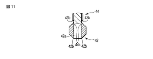
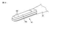
処置部42は、略平板形状を有しており、処置対象部位と接触することで、超音波振動によって処置対象部位を処置する。処置部42は、ケース11の長手軸方向(プローブ30の長手軸方向)に長径なループ形状を有している。そのため処置部42には、処置部42の厚み方向に貫通している開口部42aが形成されている。開口部42aは、開口部42aの外径において、後述する刃44aと共に処置対象部位を切断する切断部である切断エッジ42bを有している。言い換えると切断エッジ42bは、ループ内にて、プローブ30の長手軸方向に沿って配設される。切断エッジ42bは、後述する刃44aと共に処置対象部位を切断により処置する処置部本体部である。
The
この開口部42aには、処置部42に対して回動する切断部材44が挿入する。切断部材44は、開口部42a側に向けて形成される金属製の刃44aを有している。刃44aは、処置部材本体部となる。
A cutting
切断部材44は、操作部40の操作によって、処置部42を含むプローブ30に対して回動可能である。操作部40の操作に応じて切断部材44を回動させる回動機構は、図面の簡略化のために省略するが、当業者に周知の回動機構を備えることはいうまでもない。
The cutting
切断部材44が回動すると、刃44aは切断エッジ42bに向かって移動することとなる。そのとき刃44aが切断エッジ42bと重なり、刃44aと切断エッジ42bとが処置対象部位を挟むことで、刃44aと切断エッジ42bとは処置対象部位を切断する。
When the cutting
次に本実施形態における動作方法について説明する。 Next, an operation method according to this embodiment will be described.
操作部40が術者によって握られると、切断部材44が開口部42aに向かって回動する。これにより刃44aは切断エッジ42bに向かって移動することとなる。
When the operation unit 40 is gripped by the operator, the cutting
このとき処置部42と切断部材44との間には、生体組織の処置対象部位が配置される(挟み込まれる)。この状態からさらに切断部材44が開口部42aに向かい回動する。また超音波振動駆動装置にて発生した電力は、第1の実施形態と同様に超音波振動に変換される。超音波振動は、第1の実施形態と同様に増幅され、プローブ30に伝達される。このとき超音波振動は、処置部42を通じて処置対象部位に伝達される。
At this time, a treatment target site of the living tissue is disposed (sandwiched) between the
そのとき刃44aが切断エッジ42bと重なり、刃44aと切断エッジ42bとが処置対象部位を挟むことで、処置対象部位は刃44aと切断エッジ42bとによって切断される。
At that time, the
このように本実施形態では、第1の実施形態と同様の効果を得ることができる。 Thus, in this embodiment, the same effect as that of the first embodiment can be obtained.
また本実施形態では、切断部材44を開口部42aに向かって回動させ、刃44aと切断エッジ42bとによって処置対象部位を挟むことで、処置対象部位をぶれることなく切断できる。また本実施形態では、処置対象部位を挟み込んで処置するために、厚みを有する処置対象部位でも容易に切断することができる。
Moreover, in this embodiment, the cutting
なお本実施形態の処置部42の形状は、上記に限定されない。例えば図14に示すように、処置部42は、プローブ30の長手軸方向の略垂直な方向から平面視した際に、略U字形状を有していてもよい。処置部42は、処置部42を平面視した際に相対する辺の一方である第1の切断エッジ46aと、平面視した際に相対する辺の他方である第2の切断エッジ46bとを有している。第1の切断エッジ46aと第2の切断エッジ46bとは、処置部本体部である。つまり、第1の切断エッジ46aと第2の切断エッジ46bとは、平面視した際に相対するU字形状の一方の辺とU字形状の他方の辺とにそれぞれ配設されていることとなる。また第1の切断エッジ46aと第2の切断エッジ46bとは、プローブ30の長手軸方向に沿って略平行に配設されている。第1の切断エッジ46aと第2の切断エッジ46bの間の空間部48には、処置部42に対して回動する切断部材44が挿入される。
In addition, the shape of the
このように本発明は、上記実施形態そのままに限定されるものではなく、実施段階ではその要旨を逸脱しない範囲で構成要素を変形して具体化できる。また、上記実施形態に開示されている複数の構成要素の適宜な組み合せにより種々の発明を形成できる。 As described above, the present invention is not limited to the above-described embodiment as it is, and can be embodied by modifying the constituent elements without departing from the scope of the invention in the implementation stage. Further, various inventions can be formed by appropriately combining a plurality of constituent elements disclosed in the embodiment.
1…超音波処置具、2…出力用接続ケーブル、11…ケース、12…超音波振動子ユニット、12a…ホーン、13…把持部、20…シース、20b…内側チューブ、20c…外側チューブ、20d…空間部、21a…外刃(処置部材本体部)、21…せん断部材(処置部材)、30…プローブ(伝達部材)、30d…ホーン、30e…支持部材、31…処置部、31a…開口部、31b…せん断エッジ(処置部本体部)、31c…上面、31d…下面、33…処置部、33a…突起部、33b…せん断エッジ(処置部本体部)、40…操作部、42…処置部、42a…開口部、42b…切断エッジ(処置部本体部、切断部)、44…切断部材(処置部材、切断部材)、44a…刃(処置部材本体部)、46a…第1の切断エッジ、46b…第2の切断エッジ、48…空間部。
DESCRIPTION OF SYMBOLS 1 ... Ultrasonic treatment tool, 2 ... Output connection cable, 11 ... Case, 12 ... Ultrasonic transducer unit, 12a ... Horn, 13 ... Holding part, 20 ... Sheath, 20b ... Inner tube, 20c ... Outer tube, 20d ... Space part, 21a ... Outer blade (treatment member main body part), 21 ... Shear member (treatment member), 30 ... Probe (transmission member), 30d ... Horn, 30e ... Support member, 31 ... Treatment part, 31a ... Opening
Claims (8)
前記超音波振動子ユニットと基端側にて接続し、前記超音波振動子ユニットにて発生した超音波振動を基端側から先端側に伝達する伝達部材と、
前記伝達部材が挿通されるシースと、
前記シースの先端から突出するように前記伝達部材の先端に配設され、前記伝達部材から伝達される超音波振動によって処置対象部位を処置する処置部と、
前記処置部に配設され、前記処置対象部位を処置する処置部本体部と、
前記シースの先端から突出するように前記シースの中に配設され、前記処置対象部位を処置する処置部材と、
前記処置部材の先端に配設され、前記処置対象部位を処置する処置部材本体部と、
を具備し、
前記処置部材本体部が前記処置部本体部と重なることで、前記処置部材本体部と前記処置部本体部とは前記処置対象部位を処置することを特徴とする超音波処置具。 An ultrasonic transducer unit that generates ultrasonic vibrations;
A transmission member connected to the ultrasonic transducer unit on the proximal end side and transmitting ultrasonic vibration generated in the ultrasonic transducer unit from the proximal end side to the distal end side;
A sheath through which the transmission member is inserted;
A treatment section disposed at the distal end of the transmission member so as to protrude from the distal end of the sheath, and treating a treatment target site by ultrasonic vibration transmitted from the transmission member;
A treatment portion main body disposed in the treatment portion and treating the treatment target site;
A treatment member disposed in the sheath so as to protrude from the distal end of the sheath and treating the treatment target site;
A treatment member main body disposed at the distal end of the treatment member and treating the treatment target site;
Comprising
The ultrasonic treatment instrument, wherein the treatment member main body and the treatment portion main body treat the treatment target site by overlapping the treatment member main body with the treatment portion main body.
前記処置部本体部は、ループ内の前記伝達部材の長手軸方向の先端側にて、前記伝達部材の長手軸方向に対して所望に傾いて配設されていることを特徴とする請求項2に記載の超音波処置具。 The treatment portion has a loop shape having a long diameter in the longitudinal axis direction of the transmission member,
3. The treatment portion main body is disposed at a distal end side in a longitudinal axis direction of the transmission member in a loop and is inclined as desired with respect to the longitudinal axis direction of the transmission member. The ultrasonic treatment tool according to 1.
前記処置部本体部は、ループ内の前記伝達部材の長手軸方向の先端側にて、前記伝達部材の長手軸方向に対して略垂直に配設されていることを特徴とする請求項2に記載の超音波処置具。 The treatment portion has a loop shape having a long diameter in the longitudinal axis direction of the transmission member,
3. The treatment portion main body portion is disposed substantially perpendicular to the longitudinal axis direction of the transmission member at the distal end side in the longitudinal axis direction of the transmission member in the loop. The ultrasonic treatment device described.
前記突起部は、略垂直方向における前記突起部の先端に前記処置部本体部を有していることを特徴とする請求項2に記載の超音波処置具。 The treatment portion has a protrusion that rises in a direction substantially perpendicular to the longitudinal axis direction of the transmission member;
The ultrasonic treatment instrument according to claim 2, wherein the protrusion has the treatment portion main body at a tip of the protrusion in a substantially vertical direction.
前記処置部本体部は、ループ内にて、前記伝達部材の長手軸方向に沿って配設され切断部であり、
前記処置部材は、切断部材であり、
前記処置部材が前記処置部に向かって回動し、前記処置部材本体部と前記処置部本体部とが重なり、前記処置部材本体部と前記処置部本体部とが前記処置対象部位を挟むことで、前記処置部材本体部と前記処置部本体部とは前記処置対象部位を切断によって処置することを特徴とする請求項6に記載の超音波処置具。 The treatment portion has a loop shape having a long diameter in the longitudinal axis direction of the transmission member,
The treatment portion main body is a cutting portion disposed along a longitudinal axis direction of the transmission member in a loop,
The treatment member is a cutting member;
The treatment member rotates toward the treatment portion, the treatment member main body portion and the treatment portion main body portion overlap, and the treatment member main body portion and the treatment portion main body portion sandwich the treatment target site. The ultrasonic treatment instrument according to claim 6, wherein the treatment member main body and the treatment portion main body treat the treatment target site by cutting.
前記処置部本体部は、平面視した際に相対するU字形状の一方の辺とU字形状の他方の辺とにそれぞれ配設されていることを特徴とする請求項7に記載の超音波処置具。 The treatment portion has a substantially U shape when viewed in plan from a direction substantially perpendicular to the longitudinal axis direction of the transmission member;
The ultrasonic wave according to claim 7, wherein the treatment portion main body is disposed on one side of the U shape and the other side of the U shape that face each other when viewed in plan. Treatment tool.
Applications Claiming Priority (2)
| Application Number | Priority Date | Filing Date | Title |
|---|---|---|---|
| US7389908P | 2008-06-19 | 2008-06-19 | |
| US61/073,899 | 2008-06-19 |
Publications (2)
| Publication Number | Publication Date |
|---|---|
| JP2010000335A true JP2010000335A (en) | 2010-01-07 |
| JP5379501B2 JP5379501B2 (en) | 2013-12-25 |
Family
ID=41278339
Family Applications (1)
| Application Number | Title | Priority Date | Filing Date |
|---|---|---|---|
| JP2009018560A Active JP5379501B2 (en) | 2008-06-19 | 2009-01-29 | Ultrasonic treatment device |
Country Status (3)
| Country | Link |
|---|---|
| US (1) | US8236018B2 (en) |
| EP (1) | EP2135570B1 (en) |
| JP (1) | JP5379501B2 (en) |
Cited By (3)
| Publication number | Priority date | Publication date | Assignee | Title |
|---|---|---|---|---|
| JP6033503B1 (en) * | 2015-07-23 | 2016-11-30 | オリンパス株式会社 | Ultrasonic treatment device and ultrasonic treatment assembly |
| WO2018078828A1 (en) * | 2016-10-28 | 2018-05-03 | オリンパス株式会社 | Ultrasonic probe |
| WO2018078825A1 (en) * | 2016-10-28 | 2018-05-03 | オリンパス株式会社 | Ultrasonic probe |
Families Citing this family (138)
| Publication number | Priority date | Publication date | Assignee | Title |
|---|---|---|---|---|
| US10835307B2 (en) | 2001-06-12 | 2020-11-17 | Ethicon Llc | Modular battery powered handheld surgical instrument containing elongated multi-layered shaft |
| US8182501B2 (en) | 2004-02-27 | 2012-05-22 | Ethicon Endo-Surgery, Inc. | Ultrasonic surgical shears and method for sealing a blood vessel using same |
| MX2007004151A (en) | 2004-10-08 | 2007-09-11 | Johnson & Johnson | Ultrasonic surgical instrument. |
| US20070191713A1 (en) | 2005-10-14 | 2007-08-16 | Eichmann Stephen E | Ultrasonic device for cutting and coagulating |
| US7621930B2 (en) | 2006-01-20 | 2009-11-24 | Ethicon Endo-Surgery, Inc. | Ultrasound medical instrument having a medical ultrasonic blade |
| EP1835699A1 (en) * | 2006-03-17 | 2007-09-19 | ABB PATENT GmbH | Robot controller |
| US8057498B2 (en) | 2007-11-30 | 2011-11-15 | Ethicon Endo-Surgery, Inc. | Ultrasonic surgical instrument blades |
| US8226675B2 (en) | 2007-03-22 | 2012-07-24 | Ethicon Endo-Surgery, Inc. | Surgical instruments |
| US8142461B2 (en) | 2007-03-22 | 2012-03-27 | Ethicon Endo-Surgery, Inc. | Surgical instruments |
| US8911460B2 (en) | 2007-03-22 | 2014-12-16 | Ethicon Endo-Surgery, Inc. | Ultrasonic surgical instruments |
| US20080234709A1 (en) | 2007-03-22 | 2008-09-25 | Houser Kevin L | Ultrasonic surgical instrument and cartilage and bone shaping blades therefor |
| US8523889B2 (en) | 2007-07-27 | 2013-09-03 | Ethicon Endo-Surgery, Inc. | Ultrasonic end effectors with increased active length |
| US8808319B2 (en) | 2007-07-27 | 2014-08-19 | Ethicon Endo-Surgery, Inc. | Surgical instruments |
| US8348967B2 (en) | 2007-07-27 | 2013-01-08 | Ethicon Endo-Surgery, Inc. | Ultrasonic surgical instruments |
| US8882791B2 (en) | 2007-07-27 | 2014-11-11 | Ethicon Endo-Surgery, Inc. | Ultrasonic surgical instruments |
| US8512365B2 (en) | 2007-07-31 | 2013-08-20 | Ethicon Endo-Surgery, Inc. | Surgical instruments |
| US8430898B2 (en) | 2007-07-31 | 2013-04-30 | Ethicon Endo-Surgery, Inc. | Ultrasonic surgical instruments |
| US8252012B2 (en) | 2007-07-31 | 2012-08-28 | Ethicon Endo-Surgery, Inc. | Ultrasonic surgical instrument with modulator |
| US9044261B2 (en) | 2007-07-31 | 2015-06-02 | Ethicon Endo-Surgery, Inc. | Temperature controlled ultrasonic surgical instruments |
| AU2008308606B2 (en) | 2007-10-05 | 2014-12-18 | Ethicon Endo-Surgery, Inc. | Ergonomic surgical instruments |
| US10010339B2 (en) | 2007-11-30 | 2018-07-03 | Ethicon Llc | Ultrasonic surgical blades |
| US9089360B2 (en) | 2008-08-06 | 2015-07-28 | Ethicon Endo-Surgery, Inc. | Devices and techniques for cutting and coagulating tissue |
| US8058771B2 (en) | 2008-08-06 | 2011-11-15 | Ethicon Endo-Surgery, Inc. | Ultrasonic device for cutting and coagulating with stepped output |
| US9700339B2 (en) | 2009-05-20 | 2017-07-11 | Ethicon Endo-Surgery, Inc. | Coupling arrangements and methods for attaching tools to ultrasonic surgical instruments |
| US8334635B2 (en) | 2009-06-24 | 2012-12-18 | Ethicon Endo-Surgery, Inc. | Transducer arrangements for ultrasonic surgical instruments |
| US8461744B2 (en) | 2009-07-15 | 2013-06-11 | Ethicon Endo-Surgery, Inc. | Rotating transducer mount for ultrasonic surgical instruments |
| US9017326B2 (en) | 2009-07-15 | 2015-04-28 | Ethicon Endo-Surgery, Inc. | Impedance monitoring apparatus, system, and method for ultrasonic surgical instruments |
| US8663220B2 (en) | 2009-07-15 | 2014-03-04 | Ethicon Endo-Surgery, Inc. | Ultrasonic surgical instruments |
| US9168054B2 (en) | 2009-10-09 | 2015-10-27 | Ethicon Endo-Surgery, Inc. | Surgical generator for ultrasonic and electrosurgical devices |
| USRE47996E1 (en) | 2009-10-09 | 2020-05-19 | Ethicon Llc | Surgical generator for ultrasonic and electrosurgical devices |
| US10441345B2 (en) | 2009-10-09 | 2019-10-15 | Ethicon Llc | Surgical generator for ultrasonic and electrosurgical devices |
| US11090104B2 (en) | 2009-10-09 | 2021-08-17 | Cilag Gmbh International | Surgical generator for ultrasonic and electrosurgical devices |
| US8951248B2 (en) | 2009-10-09 | 2015-02-10 | Ethicon Endo-Surgery, Inc. | Surgical generator for ultrasonic and electrosurgical devices |
| US8951272B2 (en) | 2010-02-11 | 2015-02-10 | Ethicon Endo-Surgery, Inc. | Seal arrangements for ultrasonically powered surgical instruments |
| US8419759B2 (en) * | 2010-02-11 | 2013-04-16 | Ethicon Endo-Surgery, Inc. | Ultrasonic surgical instrument with comb-like tissue trimming device |
| US8961547B2 (en) | 2010-02-11 | 2015-02-24 | Ethicon Endo-Surgery, Inc. | Ultrasonic surgical instruments with moving cutting implement |
| US8579928B2 (en) | 2010-02-11 | 2013-11-12 | Ethicon Endo-Surgery, Inc. | Outer sheath and blade arrangements for ultrasonic surgical instruments |
| US8323302B2 (en) * | 2010-02-11 | 2012-12-04 | Ethicon Endo-Surgery, Inc. | Methods of using ultrasonically powered surgical instruments with rotatable cutting implements |
| US8531064B2 (en) | 2010-02-11 | 2013-09-10 | Ethicon Endo-Surgery, Inc. | Ultrasonically powered surgical instruments with rotating cutting implement |
| US8469981B2 (en) | 2010-02-11 | 2013-06-25 | Ethicon Endo-Surgery, Inc. | Rotatable cutting implement arrangements for ultrasonic surgical instruments |
| US8382782B2 (en) | 2010-02-11 | 2013-02-26 | Ethicon Endo-Surgery, Inc. | Ultrasonic surgical instruments with partially rotating blade and fixed pad arrangement |
| US8486096B2 (en) | 2010-02-11 | 2013-07-16 | Ethicon Endo-Surgery, Inc. | Dual purpose surgical instrument for cutting and coagulating tissue |
| US9259234B2 (en) | 2010-02-11 | 2016-02-16 | Ethicon Endo-Surgery, Llc | Ultrasonic surgical instruments with rotatable blade and hollow sheath arrangements |
| US8409235B2 (en) * | 2010-04-30 | 2013-04-02 | Medtronic Xomed, Inc. | Rotary cutting tool with improved cutting and reduced clogging on soft tissue and thin bone |
| GB2480498A (en) | 2010-05-21 | 2011-11-23 | Ethicon Endo Surgery Inc | Medical device comprising RF circuitry |
| US8795327B2 (en) | 2010-07-22 | 2014-08-05 | Ethicon Endo-Surgery, Inc. | Electrosurgical instrument with separate closure and cutting members |
| US9192431B2 (en) | 2010-07-23 | 2015-11-24 | Ethicon Endo-Surgery, Inc. | Electrosurgical cutting and sealing instrument |
| US9259265B2 (en) | 2011-07-22 | 2016-02-16 | Ethicon Endo-Surgery, Llc | Surgical instruments for tensioning tissue |
| EP2811932B1 (en) | 2012-02-10 | 2019-06-26 | Ethicon LLC | Robotically controlled surgical instrument |
| US9226766B2 (en) | 2012-04-09 | 2016-01-05 | Ethicon Endo-Surgery, Inc. | Serial communication protocol for medical device |
| US9241731B2 (en) | 2012-04-09 | 2016-01-26 | Ethicon Endo-Surgery, Inc. | Rotatable electrical connection for ultrasonic surgical instruments |
| US9439668B2 (en) | 2012-04-09 | 2016-09-13 | Ethicon Endo-Surgery, Llc | Switch arrangements for ultrasonic surgical instruments |
| US9724118B2 (en) | 2012-04-09 | 2017-08-08 | Ethicon Endo-Surgery, Llc | Techniques for cutting and coagulating tissue for ultrasonic surgical instruments |
| US9237921B2 (en) | 2012-04-09 | 2016-01-19 | Ethicon Endo-Surgery, Inc. | Devices and techniques for cutting and coagulating tissue |
| US20140005705A1 (en) | 2012-06-29 | 2014-01-02 | Ethicon Endo-Surgery, Inc. | Surgical instruments with articulating shafts |
| US9326788B2 (en) | 2012-06-29 | 2016-05-03 | Ethicon Endo-Surgery, Llc | Lockout mechanism for use with robotic electrosurgical device |
| US9820768B2 (en) | 2012-06-29 | 2017-11-21 | Ethicon Llc | Ultrasonic surgical instruments with control mechanisms |
| US9283045B2 (en) | 2012-06-29 | 2016-03-15 | Ethicon Endo-Surgery, Llc | Surgical instruments with fluid management system |
| US9198714B2 (en) | 2012-06-29 | 2015-12-01 | Ethicon Endo-Surgery, Inc. | Haptic feedback devices for surgical robot |
| US9226767B2 (en) | 2012-06-29 | 2016-01-05 | Ethicon Endo-Surgery, Inc. | Closed feedback control for electrosurgical device |
| US9393037B2 (en) | 2012-06-29 | 2016-07-19 | Ethicon Endo-Surgery, Llc | Surgical instruments with articulating shafts |
| US9351754B2 (en) | 2012-06-29 | 2016-05-31 | Ethicon Endo-Surgery, Llc | Ultrasonic surgical instruments with distally positioned jaw assemblies |
| US20140005702A1 (en) | 2012-06-29 | 2014-01-02 | Ethicon Endo-Surgery, Inc. | Ultrasonic surgical instruments with distally positioned transducers |
| US9408622B2 (en) | 2012-06-29 | 2016-08-09 | Ethicon Endo-Surgery, Llc | Surgical instruments with articulating shafts |
| US9492224B2 (en) | 2012-09-28 | 2016-11-15 | EthiconEndo-Surgery, LLC | Multi-function bi-polar forceps |
| US9095367B2 (en) | 2012-10-22 | 2015-08-04 | Ethicon Endo-Surgery, Inc. | Flexible harmonic waveguides/blades for surgical instruments |
| US10201365B2 (en) | 2012-10-22 | 2019-02-12 | Ethicon Llc | Surgeon feedback sensing and display methods |
| US20140135804A1 (en) | 2012-11-15 | 2014-05-15 | Ethicon Endo-Surgery, Inc. | Ultrasonic and electrosurgical devices |
| US10226273B2 (en) | 2013-03-14 | 2019-03-12 | Ethicon Llc | Mechanical fasteners for use with surgical energy devices |
| US9241728B2 (en) | 2013-03-15 | 2016-01-26 | Ethicon Endo-Surgery, Inc. | Surgical instrument with multiple clamping mechanisms |
| US9814514B2 (en) | 2013-09-13 | 2017-11-14 | Ethicon Llc | Electrosurgical (RF) medical instruments for cutting and coagulating tissue |
| US9265926B2 (en) | 2013-11-08 | 2016-02-23 | Ethicon Endo-Surgery, Llc | Electrosurgical devices |
| GB2521229A (en) | 2013-12-16 | 2015-06-17 | Ethicon Endo Surgery Inc | Medical device |
| GB2521228A (en) | 2013-12-16 | 2015-06-17 | Ethicon Endo Surgery Inc | Medical device |
| US9795436B2 (en) | 2014-01-07 | 2017-10-24 | Ethicon Llc | Harvesting energy from a surgical generator |
| US9554854B2 (en) | 2014-03-18 | 2017-01-31 | Ethicon Endo-Surgery, Llc | Detecting short circuits in electrosurgical medical devices |
| US10463421B2 (en) | 2014-03-27 | 2019-11-05 | Ethicon Llc | Two stage trigger, clamp and cut bipolar vessel sealer |
| US10092310B2 (en) | 2014-03-27 | 2018-10-09 | Ethicon Llc | Electrosurgical devices |
| US9737355B2 (en) | 2014-03-31 | 2017-08-22 | Ethicon Llc | Controlling impedance rise in electrosurgical medical devices |
| US9913680B2 (en) | 2014-04-15 | 2018-03-13 | Ethicon Llc | Software algorithms for electrosurgical instruments |
| US10285724B2 (en) | 2014-07-31 | 2019-05-14 | Ethicon Llc | Actuation mechanisms and load adjustment assemblies for surgical instruments |
| US10639092B2 (en) | 2014-12-08 | 2020-05-05 | Ethicon Llc | Electrode configurations for surgical instruments |
| US10245095B2 (en) | 2015-02-06 | 2019-04-02 | Ethicon Llc | Electrosurgical instrument with rotation and articulation mechanisms |
| US10321950B2 (en) | 2015-03-17 | 2019-06-18 | Ethicon Llc | Managing tissue treatment |
| US10342602B2 (en) | 2015-03-17 | 2019-07-09 | Ethicon Llc | Managing tissue treatment |
| US10595929B2 (en) | 2015-03-24 | 2020-03-24 | Ethicon Llc | Surgical instruments with firing system overload protection mechanisms |
| US10034684B2 (en) | 2015-06-15 | 2018-07-31 | Ethicon Llc | Apparatus and method for dissecting and coagulating tissue |
| US11020140B2 (en) | 2015-06-17 | 2021-06-01 | Cilag Gmbh International | Ultrasonic surgical blade for use with ultrasonic surgical instruments |
| US11051873B2 (en) | 2015-06-30 | 2021-07-06 | Cilag Gmbh International | Surgical system with user adaptable techniques employing multiple energy modalities based on tissue parameters |
| US10765470B2 (en) | 2015-06-30 | 2020-09-08 | Ethicon Llc | Surgical system with user adaptable techniques employing simultaneous energy modalities based on tissue parameters |
| US10034704B2 (en) | 2015-06-30 | 2018-07-31 | Ethicon Llc | Surgical instrument with user adaptable algorithms |
| US10357303B2 (en) | 2015-06-30 | 2019-07-23 | Ethicon Llc | Translatable outer tube for sealing using shielded lap chole dissector |
| US10898256B2 (en) | 2015-06-30 | 2021-01-26 | Ethicon Llc | Surgical system with user adaptable techniques based on tissue impedance |
| US11129669B2 (en) | 2015-06-30 | 2021-09-28 | Cilag Gmbh International | Surgical system with user adaptable techniques based on tissue type |
| US10154852B2 (en) | 2015-07-01 | 2018-12-18 | Ethicon Llc | Ultrasonic surgical blade with improved cutting and coagulation features |
| WO2017027745A1 (en) | 2015-08-11 | 2017-02-16 | Reach Surgical, Inc. | Double hook ultrasonic surgical blade |
| US10687884B2 (en) | 2015-09-30 | 2020-06-23 | Ethicon Llc | Circuits for supplying isolated direct current (DC) voltage to surgical instruments |
| US10595930B2 (en) | 2015-10-16 | 2020-03-24 | Ethicon Llc | Electrode wiping surgical device |
| US10179022B2 (en) | 2015-12-30 | 2019-01-15 | Ethicon Llc | Jaw position impedance limiter for electrosurgical instrument |
| US10575892B2 (en) | 2015-12-31 | 2020-03-03 | Ethicon Llc | Adapter for electrical surgical instruments |
| US11129670B2 (en) | 2016-01-15 | 2021-09-28 | Cilag Gmbh International | Modular battery powered handheld surgical instrument with selective application of energy based on button displacement, intensity, or local tissue characterization |
| US10251664B2 (en) | 2016-01-15 | 2019-04-09 | Ethicon Llc | Modular battery powered handheld surgical instrument with multi-function motor via shifting gear assembly |
| US11229471B2 (en) | 2016-01-15 | 2022-01-25 | Cilag Gmbh International | Modular battery powered handheld surgical instrument with selective application of energy based on tissue characterization |
| US10716615B2 (en) | 2016-01-15 | 2020-07-21 | Ethicon Llc | Modular battery powered handheld surgical instrument with curved end effectors having asymmetric engagement between jaw and blade |
| US10555769B2 (en) | 2016-02-22 | 2020-02-11 | Ethicon Llc | Flexible circuits for electrosurgical instrument |
| US10646269B2 (en) | 2016-04-29 | 2020-05-12 | Ethicon Llc | Non-linear jaw gap for electrosurgical instruments |
| US10485607B2 (en) | 2016-04-29 | 2019-11-26 | Ethicon Llc | Jaw structure with distal closure for electrosurgical instruments |
| US10702329B2 (en) | 2016-04-29 | 2020-07-07 | Ethicon Llc | Jaw structure with distal post for electrosurgical instruments |
| US10456193B2 (en) | 2016-05-03 | 2019-10-29 | Ethicon Llc | Medical device with a bilateral jaw configuration for nerve stimulation |
| US10245064B2 (en) | 2016-07-12 | 2019-04-02 | Ethicon Llc | Ultrasonic surgical instrument with piezoelectric central lumen transducer |
| US10893883B2 (en) | 2016-07-13 | 2021-01-19 | Ethicon Llc | Ultrasonic assembly for use with ultrasonic surgical instruments |
| US10842522B2 (en) | 2016-07-15 | 2020-11-24 | Ethicon Llc | Ultrasonic surgical instruments having offset blades |
| US10376305B2 (en) | 2016-08-05 | 2019-08-13 | Ethicon Llc | Methods and systems for advanced harmonic energy |
| US10285723B2 (en) | 2016-08-09 | 2019-05-14 | Ethicon Llc | Ultrasonic surgical blade with improved heel portion |
| USD847990S1 (en) | 2016-08-16 | 2019-05-07 | Ethicon Llc | Surgical instrument |
| US10779847B2 (en) | 2016-08-25 | 2020-09-22 | Ethicon Llc | Ultrasonic transducer to waveguide joining |
| US10952759B2 (en) | 2016-08-25 | 2021-03-23 | Ethicon Llc | Tissue loading of a surgical instrument |
| CN109792580B (en) * | 2016-09-30 | 2020-11-10 | 奥林巴斯株式会社 | Ultrasonic transducer and method for manufacturing ultrasonic transducer |
| US10603064B2 (en) | 2016-11-28 | 2020-03-31 | Ethicon Llc | Ultrasonic transducer |
| US11266430B2 (en) | 2016-11-29 | 2022-03-08 | Cilag Gmbh International | End effector control and calibration |
| US10820920B2 (en) | 2017-07-05 | 2020-11-03 | Ethicon Llc | Reusable ultrasonic medical devices and methods of their use |
| US11786259B1 (en) * | 2019-05-28 | 2023-10-17 | Mirus Llc | Systems and methods for ultrasonically-assisted placement of orthopedic implants |
| US11452525B2 (en) | 2019-12-30 | 2022-09-27 | Cilag Gmbh International | Surgical instrument comprising an adjustment system |
| US11911063B2 (en) | 2019-12-30 | 2024-02-27 | Cilag Gmbh International | Techniques for detecting ultrasonic blade to electrode contact and reducing power to ultrasonic blade |
| US20210196349A1 (en) | 2019-12-30 | 2021-07-01 | Ethicon Llc | Electrosurgical instrument with flexible wiring assemblies |
| US11786294B2 (en) | 2019-12-30 | 2023-10-17 | Cilag Gmbh International | Control program for modular combination energy device |
| US11944366B2 (en) | 2019-12-30 | 2024-04-02 | Cilag Gmbh International | Asymmetric segmented ultrasonic support pad for cooperative engagement with a movable RF electrode |
| US11786291B2 (en) | 2019-12-30 | 2023-10-17 | Cilag Gmbh International | Deflectable support of RF energy electrode with respect to opposing ultrasonic blade |
| US20210196361A1 (en) | 2019-12-30 | 2021-07-01 | Ethicon Llc | Electrosurgical instrument with monopolar and bipolar energy capabilities |
| US11937866B2 (en) | 2019-12-30 | 2024-03-26 | Cilag Gmbh International | Method for an electrosurgical procedure |
| US11696776B2 (en) | 2019-12-30 | 2023-07-11 | Cilag Gmbh International | Articulatable surgical instrument |
| US11660089B2 (en) | 2019-12-30 | 2023-05-30 | Cilag Gmbh International | Surgical instrument comprising a sensing system |
| US11950797B2 (en) | 2019-12-30 | 2024-04-09 | Cilag Gmbh International | Deflectable electrode with higher distal bias relative to proximal bias |
| US11812957B2 (en) | 2019-12-30 | 2023-11-14 | Cilag Gmbh International | Surgical instrument comprising a signal interference resolution system |
| US11937863B2 (en) | 2019-12-30 | 2024-03-26 | Cilag Gmbh International | Deflectable electrode with variable compression bias along the length of the deflectable electrode |
| US11684412B2 (en) | 2019-12-30 | 2023-06-27 | Cilag Gmbh International | Surgical instrument with rotatable and articulatable surgical end effector |
| US11779387B2 (en) | 2019-12-30 | 2023-10-10 | Cilag Gmbh International | Clamp arm jaw to minimize tissue sticking and improve tissue control |
| US11779329B2 (en) | 2019-12-30 | 2023-10-10 | Cilag Gmbh International | Surgical instrument comprising a flex circuit including a sensor system |
Citations (7)
| Publication number | Priority date | Publication date | Assignee | Title |
|---|---|---|---|---|
| JPH05220157A (en) * | 1992-02-18 | 1993-08-31 | Olympus Optical Co Ltd | Excision device for medical treatment |
| JPH09131350A (en) * | 1995-11-10 | 1997-05-20 | Olympus Optical Co Ltd | Ultrasonic coagulation and incision device |
| JPH105237A (en) * | 1996-06-26 | 1998-01-13 | Olympus Optical Co Ltd | Ultrasonic processor |
| US6117152A (en) * | 1999-06-18 | 2000-09-12 | Ethicon Endo-Surgery, Inc. | Multi-function ultrasonic surgical instrument |
| JP2001524842A (en) * | 1996-10-04 | 2001-12-04 | ユナイテッド ステイツ サージカル コーポレイション | Ultrasound incision and coagulation system |
| JP2002224133A (en) * | 2001-02-02 | 2002-08-13 | Olympus Optical Co Ltd | Ultrasonic treatment apparatus |
| JP2003116863A (en) * | 2001-10-10 | 2003-04-22 | Olympus Optical Co Ltd | Ultrasonic treating apparatus |
Family Cites Families (8)
| Publication number | Priority date | Publication date | Assignee | Title |
|---|---|---|---|---|
| US6056735A (en) | 1996-04-04 | 2000-05-02 | Olympus Optical Co., Ltd. | Ultrasound treatment system |
| US5906628A (en) | 1996-06-26 | 1999-05-25 | Olympus Optical Co., Ltd. | Ultrasonic treatment instrument |
| US6231578B1 (en) | 1998-08-05 | 2001-05-15 | United States Surgical Corporation | Ultrasonic snare for excising tissue |
| JP2002143177A (en) | 2000-11-07 | 2002-05-21 | Miwatec:Kk | Ultrasonic hand piece and ultrasonic horn used therefor |
| US7229455B2 (en) | 2001-09-03 | 2007-06-12 | Olympus Corporation | Ultrasonic calculus treatment apparatus |
| US20030204199A1 (en) * | 2002-04-30 | 2003-10-30 | Novak Theodore A. D. | Device and method for ultrasonic tissue excision with tissue selectivity |
| US20030212422A1 (en) * | 2002-05-13 | 2003-11-13 | Paul Fenton | Ultrasonic soft tissue cutting and coagulation systems with movable vibrating probe and fixed receiving clamp |
| US7645278B2 (en) | 2006-02-22 | 2010-01-12 | Olympus Corporation | Coagulating cutter |
-
2009
- 2009-01-29 JP JP2009018560A patent/JP5379501B2/en active Active
- 2009-04-06 US US12/418,667 patent/US8236018B2/en active Active
- 2009-04-08 EP EP09005173.1A patent/EP2135570B1/en not_active Not-in-force
Patent Citations (7)
| Publication number | Priority date | Publication date | Assignee | Title |
|---|---|---|---|---|
| JPH05220157A (en) * | 1992-02-18 | 1993-08-31 | Olympus Optical Co Ltd | Excision device for medical treatment |
| JPH09131350A (en) * | 1995-11-10 | 1997-05-20 | Olympus Optical Co Ltd | Ultrasonic coagulation and incision device |
| JPH105237A (en) * | 1996-06-26 | 1998-01-13 | Olympus Optical Co Ltd | Ultrasonic processor |
| JP2001524842A (en) * | 1996-10-04 | 2001-12-04 | ユナイテッド ステイツ サージカル コーポレイション | Ultrasound incision and coagulation system |
| US6117152A (en) * | 1999-06-18 | 2000-09-12 | Ethicon Endo-Surgery, Inc. | Multi-function ultrasonic surgical instrument |
| JP2002224133A (en) * | 2001-02-02 | 2002-08-13 | Olympus Optical Co Ltd | Ultrasonic treatment apparatus |
| JP2003116863A (en) * | 2001-10-10 | 2003-04-22 | Olympus Optical Co Ltd | Ultrasonic treating apparatus |
Cited By (5)
| Publication number | Priority date | Publication date | Assignee | Title |
|---|---|---|---|---|
| JP6033503B1 (en) * | 2015-07-23 | 2016-11-30 | オリンパス株式会社 | Ultrasonic treatment device and ultrasonic treatment assembly |
| WO2018078828A1 (en) * | 2016-10-28 | 2018-05-03 | オリンパス株式会社 | Ultrasonic probe |
| WO2018078970A1 (en) * | 2016-10-28 | 2018-05-03 | オリンパス株式会社 | Ultrasonic probe |
| WO2018078825A1 (en) * | 2016-10-28 | 2018-05-03 | オリンパス株式会社 | Ultrasonic probe |
| US10987122B2 (en) | 2016-10-28 | 2021-04-27 | Olympus Corporation | Ultrasonic probe |
Also Published As
| Publication number | Publication date |
|---|---|
| JP5379501B2 (en) | 2013-12-25 |
| EP2135570A3 (en) | 2009-12-30 |
| EP2135570B1 (en) | 2016-12-07 |
| EP2135570A2 (en) | 2009-12-23 |
| US8236018B2 (en) | 2012-08-07 |
| US20090318945A1 (en) | 2009-12-24 |
Similar Documents
| Publication | Publication Date | Title |
|---|---|---|
| JP5379501B2 (en) | Ultrasonic treatment device | |
| US10835768B2 (en) | Dual purpose surgical instrument for cutting and coagulating tissue | |
| JP5930247B2 (en) | Ultrasonic surgical device | |
| EP1049411B1 (en) | Ultrasonic cutting tool | |
| US8382782B2 (en) | Ultrasonic surgical instruments with partially rotating blade and fixed pad arrangement | |
| EP3524190B1 (en) | Ultrasonic bone cutting instrument | |
| JP2005040222A (en) | Ultrasonic treatment apparatus | |
| JP2003116870A (en) | Ultrasonic hand piece and ultrasonic horn used for this | |
| JP2009247892A (en) | Ultrasonic needle driver | |
| JPH10127654A (en) | Ultrasonic treatment tool | |
| JP2002143177A (en) | Ultrasonic hand piece and ultrasonic horn used therefor | |
| JP6151776B2 (en) | Ultrasonic surgical micromotor | |
| US20150182249A1 (en) | Loading features for ultrasonic surgical instrument |
Legal Events
| Date | Code | Title | Description |
|---|---|---|---|
| A621 | Written request for application examination |
Free format text: JAPANESE INTERMEDIATE CODE: A621 Effective date: 20111116 |
|
| A977 | Report on retrieval |
Free format text: JAPANESE INTERMEDIATE CODE: A971007 Effective date: 20130225 |
|
| A131 | Notification of reasons for refusal |
Free format text: JAPANESE INTERMEDIATE CODE: A131 Effective date: 20130312 |
|
| A521 | Request for written amendment filed |
Free format text: JAPANESE INTERMEDIATE CODE: A523 Effective date: 20130502 |
|
| TRDD | Decision of grant or rejection written | ||
| A01 | Written decision to grant a patent or to grant a registration (utility model) |
Free format text: JAPANESE INTERMEDIATE CODE: A01 Effective date: 20130910 |
|
| A61 | First payment of annual fees (during grant procedure) |
Free format text: JAPANESE INTERMEDIATE CODE: A61 Effective date: 20130927 |
|
| R151 | Written notification of patent or utility model registration |
Ref document number: 5379501 Country of ref document: JP Free format text: JAPANESE INTERMEDIATE CODE: R151 |
|
| S111 | Request for change of ownership or part of ownership |
Free format text: JAPANESE INTERMEDIATE CODE: R313111 |
|
| R350 | Written notification of registration of transfer |
Free format text: JAPANESE INTERMEDIATE CODE: R350 |
|
| S531 | Written request for registration of change of domicile |
Free format text: JAPANESE INTERMEDIATE CODE: R313531 |
|
| R350 | Written notification of registration of transfer |
Free format text: JAPANESE INTERMEDIATE CODE: R350 |
|
| R250 | Receipt of annual fees |
Free format text: JAPANESE INTERMEDIATE CODE: R250 |
|
| R250 | Receipt of annual fees |
Free format text: JAPANESE INTERMEDIATE CODE: R250 |
|
| R250 | Receipt of annual fees |
Free format text: JAPANESE INTERMEDIATE CODE: R250 |
|
| R250 | Receipt of annual fees |
Free format text: JAPANESE INTERMEDIATE CODE: R250 |
|
| R250 | Receipt of annual fees |
Free format text: JAPANESE INTERMEDIATE CODE: R250 |