JP2010000019A - Fertilizer apparatus - Google Patents
Fertilizer apparatus Download PDFInfo
- Publication number
- JP2010000019A JP2010000019A JP2008160200A JP2008160200A JP2010000019A JP 2010000019 A JP2010000019 A JP 2010000019A JP 2008160200 A JP2008160200 A JP 2008160200A JP 2008160200 A JP2008160200 A JP 2008160200A JP 2010000019 A JP2010000019 A JP 2010000019A
- Authority
- JP
- Japan
- Prior art keywords
- mud
- fertilizer
- measuring
- electrical conductivity
- fertilization
- Prior art date
- Legal status (The legal status is an assumption and is not a legal conclusion. Google has not performed a legal analysis and makes no representation as to the accuracy of the status listed.)
- Granted
Links
- 239000003337 fertilizer Substances 0.000 title claims abstract description 89
- 230000004720 fertilization Effects 0.000 claims abstract description 55
- 239000002689 soil Substances 0.000 claims abstract description 33
- 230000035558 fertility Effects 0.000 claims abstract description 32
- 238000005259 measurement Methods 0.000 claims description 16
- 230000007423 decrease Effects 0.000 claims description 10
- 238000009331 sowing Methods 0.000 claims description 3
- 238000000034 method Methods 0.000 description 12
- 238000003860 storage Methods 0.000 description 9
- 241000209094 Oryza Species 0.000 description 6
- 235000007164 Oryza sativa Nutrition 0.000 description 6
- 235000009566 rice Nutrition 0.000 description 6
- 238000007542 hardness measurement Methods 0.000 description 4
- 241000196324 Embryophyta Species 0.000 description 2
- 230000003247 decreasing effect Effects 0.000 description 2
- 238000001514 detection method Methods 0.000 description 2
- 238000005527 soil sampling Methods 0.000 description 2
- XLYOFNOQVPJJNP-UHFFFAOYSA-N water Substances O XLYOFNOQVPJJNP-UHFFFAOYSA-N 0.000 description 2
- 239000004020 conductor Substances 0.000 description 1
- 238000010586 diagram Methods 0.000 description 1
- 230000005611 electricity Effects 0.000 description 1
- 230000007613 environmental effect Effects 0.000 description 1
- 231100000502 fertility decrease Toxicity 0.000 description 1
- 238000003306 harvesting Methods 0.000 description 1
- 239000007788 liquid Substances 0.000 description 1
- 238000007790 scraping Methods 0.000 description 1
- 239000007921 spray Substances 0.000 description 1
- 238000005507 spraying Methods 0.000 description 1
Images


Landscapes
- Fertilizing (AREA)
- Transplanting Machines (AREA)
Abstract
Description
本発明は施肥装置に関し、詳しくは泥部を走行する走行手段と、泥部の土壌特性を測定する測定手段と、泥部に肥料を施す施肥手段とを備えた施肥装置に関する。 The present invention relates to a fertilizer application, and more particularly, to a fertilizer application apparatus including travel means for traveling in a mud, measurement means for measuring soil characteristics of the mud, and fertilizer for applying fertilizer to the mud.
従来、水田を走行する走行手段と、水田に肥料を施す施肥手段とを備えた施肥装置が知られている。
このような施肥装置として、水田の硬盤層から水田表面までの距離を検出する水田深さ検出装置を備えたものが知られ、水田の深さが深くなると施肥量を少量にするようになっている(特許文献1)
また、予め土壌サンプリング車などによって土壌データとその測定位置とを記憶しておき、この測定結果に応じて施肥量を変化させながら施肥を行う施肥装置も知られている(特許文献2)。
As such a fertilizer, what is equipped with a paddy depth detection device that detects the distance from the hard disk layer of the paddy field to the paddy surface is known, and when the depth of the paddy field becomes deeper, the amount of fertilizer is reduced to a small amount (Patent Document 1)
There is also known a fertilizer application device that stores soil data and its measurement position in advance using a soil sampling vehicle or the like, and performs fertilization while changing the fertilization amount according to the measurement result (Patent Document 2).
ここで、上記特許文献1の施肥装置は、水田の深さが深くなると車輪がスリップして走行速度が遅くなり、その部分の施肥量が相対的に多くなってしまうことを防止するため、施肥量を少なくするものであり、水田全体に均等に施肥することが目的となっている。
しかしながら、水田によっては場所毎に土壌特性が異なっている場合があり、均一に施肥をした場合、場所によっては過剰施肥となって倒伏や米品質が低下することがあるなど、同じ水田でも品質のばらつきが発生するという問題があった。
また、特許文献2の施肥装置では、予め土壌データを土壌サンプリング車などによって収集しなければならず、リアルタイムに土壌特性を測定して施肥を行うことができないものであった。
このような問題に鑑み、本発明は土壌特性に応じた施肥を行うことができ、かつ効率的に施肥を行うことの可能な施肥装置を提供するものである。
Here, the fertilizer application of the said
However, depending on the paddy field, the soil characteristics may be different from place to place, and when uniformly fertilized, depending on the place, there may be over fertilization and lodging or rice quality may be reduced. There was a problem that variations occurred.
Moreover, in the fertilizer application apparatus of
In view of such problems, the present invention provides a fertilizer application apparatus that can perform fertilization according to soil characteristics and can efficiently perform fertilization.
すなわち、請求項1に記載の施肥装置は、硬盤層上の泥部を走行する走行手段と、上記泥部の土壌特性を測定する測定手段と、泥部に肥料を施す施肥手段とを備えた施肥装置において、
上記測定手段は、土壌特性としての泥部の深度を測定する深度測定手段と、土壌特性としての泥部の電気伝導度を測定する電気伝導度測定手段とを備え、
さらに、上記泥部の深度および電気伝導度とから肥沃度を求めるとともに、該肥沃度に応じて上記施肥手段による施肥量を制御する制御手段を設けたことを特徴としている。
That is, the fertilizer application device according to
The measuring means includes depth measuring means for measuring the depth of the mud as soil characteristics, and electrical conductivity measuring means for measuring the electrical conductivity of the mud as soil characteristics,
Further, the present invention is characterized in that a fertilizer is obtained from the depth and electrical conductivity of the mud and control means is provided for controlling the fertilization amount by the fertilizer according to the fertility.
上記発明によれば、泥部の深度と電気伝導度から肥沃度を求め、この肥沃度に応じて施肥量を制御するので、場所ごとに異なる土壌特性に応じて適切な量の肥料を施肥することができる。また、土壌測定と施肥とを同時に行うことができ、効率的な施肥を行うことができる。 According to the above invention, the fertility is obtained from the depth and electrical conductivity of the mud, and the amount of fertilization is controlled according to the fertility, so that an appropriate amount of fertilizer is applied according to different soil characteristics for each place be able to. Moreover, soil measurement and fertilization can be performed simultaneously, and efficient fertilization can be performed.
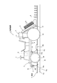
以下、図示実施例について説明すると、図1は本発明にかかる施肥装置1を示し、水田Fを走行する走行手段2と、水田Fに苗Rの植付を行う植付手段3と、水田Fに肥料を施す施肥手段4と、水田Fの土壌特性を測定する測定手段5とを備え、これらは制御手段6に接続されている。
上記水田Fは、走行手段2が走行する硬盤層Faの上に泥部Fbが形成された状態となっており、走行手段2は泥部Fbに沈んだ状態で硬盤層Fa上を走行するようになっている。また本実施例では、通常は張られている泥部Fbの上部の水が予め抜かれている。
そして上記施肥装置1によれば、走行手段2が水田Fを走行すると、上記測定手段5が走行した部分の泥部Fbの土壌特性を測定し、制御手段6で泥部Fbの肥沃度を求めるとともに、施肥手段4を制御して土壌特性に応じた適切な量の肥料を施肥し、併せて上記植付手段3により苗Rの植付を行うようになっている。
このようにすることで、水田F全体の土壌特性を均一とすることができ、また土壌特性の測定と同時に苗Rの植付を行うことができるので、安定した収穫を期待できるとともに効率的な農作業を行うことができる。
Hereinafter, the illustrated embodiment will be described. FIG. 1 shows a
The paddy field F is in a state in which a mud portion Fb is formed on the hard disk layer Fa on which the traveling means 2 travels, and the traveling means 2 travels on the hard disk layer Fa while being submerged in the mud portion Fb. It has become. In the present embodiment, the water on the upper part of the mud Fb that is normally stretched is previously removed.
According to the
By doing in this way, the soil characteristic of the whole paddy field F can be made uniform, and since the seedling R can be planted simultaneously with the measurement of the soil characteristic, stable harvest can be expected and efficient. Agricultural work can be done.
上記走行手段2には従来公知のトラクタを利用することができ、また走行手段2と植付手段3からなる従来公知の田植え機を用いることができる。なお、図示運転席やハンドルを備えた走行手段の他、他の構成を有する従来公知の走行手段を使用することができる。
上記植付手段3は従来公知であって詳細な説明は省略するが、苗Rを走行手段2の幅方向に等間隔に植付けるととともに、走行手段2の走行速度に応じて所定間隔で苗Rを植えるようになっている。
また走行手段2には、走行手段2の位置を測定する位置測定手段7と、走行手段2の絶対速度を測定する速度測定手段8とが設けられている。
位置測定手段7にはGPS(Global Positioning System)を用いることができ、走行手段2が水田Fを走行すると、該走行手段2の位置情報を順次取得するようになっている。
上記速度測定手段8は、超音波速度計など、水田Fの表面に対する走行手段2の対地絶対速度を測定するセンサであって、走行手段2が備える速度計では、泥部Fbにより車輪が空転すると正確な速度が測定できないことから、速度測定手段8による絶対速度を測定するようになっている。
A conventionally known tractor can be used as the traveling means 2, and a conventionally known rice planting machine comprising the traveling means 2 and the planting means 3 can be used. In addition to the traveling means provided with the illustrated driver's seat and steering wheel, conventionally known traveling means having other configurations can be used.
Although the said planting means 3 is conventionally well-known and detailed description is abbreviate | omitted, while planting the seedling R at equal intervals in the width direction of the traveling means 2, it is seedling at predetermined intervals according to the traveling speed of the traveling means 2. R is planted.
The
The position measuring means 7 can be a GPS (Global Positioning System). When the traveling means 2 travels on the paddy field F, the position information of the traveling means 2 is sequentially acquired.
The speed measuring means 8 is a sensor for measuring the absolute speed of the traveling means 2 with respect to the surface of the paddy field F, such as an ultrasonic speedometer. In the speedometer provided in the traveling means 2, the wheel is idled by the mud Fb. Since an accurate speed cannot be measured, the absolute speed by the speed measuring means 8 is measured.
上記施肥手段4は、粒状肥料を収容したタンク11と、該タンク11から所定量の肥料を送出する送出手段12と、肥料を散布するノズル13とから構成され、上記制御手段6が送出手段12を制御することで、施肥量を調整することが可能となっている。
このような施肥手段4は、植付手段3で植えつけられる苗Rの列数に応じて設けられ、上記ノズル13は苗Rが植付けられる位置をめがけて肥料を散布するようになっている。
また、本実施例では、上記ノズル13は上記植付手段3よりも前方に設けられており、走行手段2が走行すると、先にノズル13から肥料を散布し、その後植付手段3が肥料の散布された位置に苗Rを植付けるようになっている。
なお、ノズル13を植付手段3の植付位置近傍に位置させ、植付と同時に施肥するようにしても良く、施肥手段4で施肥する肥料は粒状に限らず、液状であっても良い。
The fertilizer application means 4 comprises a
Further, in this embodiment, the
The
上記測定手段5は、泥部Fbの深度を測定する深度測定手段14と、泥部Fbの電気伝導度を測定する電気伝導度測定手段15と、泥部Fbの硬さを測定する硬軟測定手段16とから構成されている。
上記深度測定手段14は、上記走行手段2の下面に設けられた第1ポテンショメータ14aと、第1ポテンショメータ14aに回転可能に設けられた第1ロッド14bと、該第1ロッド14bの先端に設けられたフロート14cとから構成されている。
フロート14cは泥部Fbの表面に浮上するようになっており、泥部Fbの深さが変化して走行手段2の位置が上下に変動すると、走行手段2に対して相対的に上下動するようになっている。
走行手段2に対してフロート14cが上下動することにより、上記第1ロッド14bが第1ポテンショメータ14aを中心に回転し、第1ポテンショメータ14aはこの第1ロッド14bの回転角度に基づいて泥部Fbの深さの変化を測定する。
The measuring means 5 includes a depth measuring means 14 for measuring the depth of the mud Fb, an electric conductivity measuring means 15 for measuring the electric conductivity of the mud Fb, and a hardness measuring means for measuring the hardness of the mud Fb. 16.
The depth measuring
The
When the
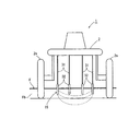
上記電気伝導度測定手段15は、図3に示すように走行手段2の車輪2a(例えば前輪)の内側に設けられた2つの円盤状の電極15aと、これら電極15aに電流を印加する図示しない電流発生手段と、電極15aの泥部Fbへの沈下量を測定する図示しない沈下センサと、電極15a間の電圧を測定する図示しない電圧測定手段と、上記沈下量と電圧とから電気伝導度を算出する電気伝導度算出手段とから構成されている。
上記電極15aは、走行手段2に対して絶縁状態で車輪2aに固定されており、その外径は車輪2aと略同径もしくは若干小径となっている。このため、泥部Fbには電極15aの一部が常時沈下しており、この沈下量は上記沈下センサによって測定される。
このように、本実施例の電気伝導度測定手段15は2つの電極15aを備えており、いわゆる2端子法により電気伝導度を測定するようになっている。
具体的には、上記電流発生手段が一方の電極15aに電流を印加すると、この電流は泥部Fbを介して他方の電極15aに流れ、上記電圧測定手段は2つの電極15a,15a間の電圧を測定する。
そして、電気伝導度算出手段は、上記沈下センサによる電極15aの沈下量と、2つの電極15a,15a間を流れる電流値と、電圧測定手段が測定した電圧とから、泥部Fbの電気伝導度を算出するようになっている。
なお、上記電極15aとして、車輪2aが導電体である場合には上記電極15aに代えて該車輪2aをそのまま用いることが可能である。
As shown in FIG. 3, the electric conductivity measuring means 15 includes two disk-
The
As described above, the electrical conductivity measuring means 15 of this embodiment includes the two
Specifically, when the current generating means applies a current to one
Then, the electrical conductivity calculating means calculates the electrical conductivity of the mud Fb from the sinking amount of the
If the
上記硬軟測定手段16は、上記走行手段2の下面に設けられた第2ポテンショメータ16aと、第2ポテンショメータ16aに回転可能に設けられた第2ロッド16bとから構成されている。
上記第2ロッド16bは第2ポテンショメータ16aから下方に向けて設けられており、走行手段2の進行方向前方に付勢された状態で、その下端が泥部Fb内に挿入されるようになっている。
このような構成により、走行手段2が走行すると、泥部Fbの抵抗によって第2ロッド16bの下端が後方に押され、これにより第2ロッド16bが第2ポテンショメータ16aに対して回転するので、第2ポテンショメータ16aはこの第2ロッド16bの回転角度に基づいて泥部Fbの硬さの変化を測定する。
なお、第2ポテンショメータ16aに代えて、歪センサやロードセルを設け、泥部Fbの抵抗により、第2ロッド16bに印加された応力を検出して、硬さの変化を測定するようにしてもよい。
The hardness measurement means 16 is composed of a
The
With such a configuration, when the traveling means 2 travels, the lower end of the
Instead of the
上記制御手段6は、図2に示すように、上記測定手段5などから土壌特性などに関する信号を受信する信号処理部21と、測定された土壌特性から施肥量を算出する施肥量算出部22と、該施肥量に応じて上記施肥手段4を制御する施肥手段制御部23と、上記植付手段3を制御する植付手段制御部24と、施肥量や土壌特性を記憶する記憶部25と、作業者による設定操作などを行うための入力表示手段26とを備えている。
信号処理部21は、それぞれ位置測定手段7、速度測定手段8、深度測定手段14、電気伝導度測定手段15、硬軟測定手段16から、それぞれ走行手段2の位置情報および絶対速度、泥部Fbの深度、泥部Fbの電気伝導度、泥部Fbの硬さの情報を入力し、処理するようになっている。
施肥量算出部22では、水田Fの各位置ごとに、上記深度測定手段14、電気伝導度測定手段15、硬軟測定手段16が測定した各土壌特性に関するデータから、後述する手順で施肥量を算出するようになっている。
上記施肥手段制御部23は、上記施肥手段4の送出手段12を制御し、上記施肥量算出部22が算出した施肥量に応じて上記施肥手段4による施肥量を制御するようになっている。
上記植付手段制御部24は、上記速度測定手段8による走行手段2の絶対速度に基づいて、苗Rを等間隔で植付るよう、上記植付手段3の動作を制御するようになっている。
上記記憶部25には、位置測定手段7が測定した位置情報とともに、その位置情報に関する上記土壌特性のデータや施肥量を記憶し、また以下に説明する施肥量の算出に使用する各定数などを記憶し、さらに、過去の土壌特性の測定データや施肥量を記憶するようになっている。
上記入力表示手段26は、上記測定手段5による測定結果や上記施肥量算出部22が算出した施肥量などを表示するモニタや、上記記憶部25に施肥量の算出に使用する各定数などを登録するための入力手段を備えている。
As shown in FIG. 2, the control means 6 includes a
The
In the fertilizer application
The fertilizing means
The planting means
The
The input display means 26 registers a monitor for displaying the measurement result by the measurement means 5 and the fertilization amount calculated by the fertilization
以下、図4を用いながら、上記施肥装置1を用いた水田Fへの施肥作業について説明する。
最初に、作業者の操作により走行手段2が水田F内に入ると、上記位置測定手段7が走行手段2の位置を測定し、この「位置情報:P」が制御手段6の信号処理部21を介して施肥量算出部22に取得される。
これと同時に、上記深度測定手段14、電気伝導度測定手段15、硬軟測定手段16がそれぞれ「泥部の電気伝導度:EC」、「泥部の深度:D」、「泥部の硬度:H」を測定し、それぞれ信号処理部21を介して施肥量算出部22に取得される(101)。
Hereinafter, the fertilization work to the paddy field F using the
First, when the traveling means 2 enters the paddy field F by the operator's operation, the position measuring means 7 measures the position of the traveling means 2, and this “position information: P” is the
At the same time, the depth measuring means 14, the electrical conductivity measuring means 15, and the hardness / softness measuring means 16 are “mud electrical conductivity: EC”, “mud depth: D”, and “mud hardness: H”, respectively. Is measured and obtained by the fertilizer application
次に施肥量算出部22は、記憶部25から「位置情報:P」に関連付けて「過去の電気伝導度:ECo」、「過去の深度:Do」を検索する(102)。
これらのデータが記憶部25に記憶されていない場合には、そのまま後述する手順(107)に移行し、これら過去のデータが記憶されている場合には、これに基づいて水田Fの中の各位置ごとに「過去の肥沃度:Fo」を算出する(103)。このときの計算式は以下の通りである。
Fo=ECo×Do…(式1)
次に、水田Fの中の各位置毎の「過去の肥沃度:Fo」から、水田F全体の「過去の肥沃度の平均値:Fa」および「過去の肥沃度の標準偏差:Fd」を算出する(104)。
さらに、施肥量算出部22は「位置情報:P」に関連付けられた「過去の硬度:Ho」を呼び出すとともに、あわせて水田F全体の「過去の硬度の平均値:Ha」および「過去の硬度の標準偏差:Hd」をそれぞれ算出する(105)。ここで、過去のデータとしては直近のデータを用いることが望ましい。
そして、施肥量算出部22は「肥沃度の基準値:Fs」を算出する(106)。このときの計算式は以下の通りである。
Fs=Fa(1+C)…(式2)
ここで、Cは任意定数で適宜変更可能であり、通常は0に設定されている。
なお上記「肥沃度の基準値:Fs」については、別途測定した水田Fの土壌特性などから、推定した値を使用することも可能である。さらには、これらの値の算出を予め作業前に行っておくことで、施肥量の算出時間を短縮できる。
Next, the fertilizer application
If these data are not stored in the
Fo = ECo × Do (Formula 1)
Next, from the “past fertility: Fo” for each position in the paddy field F, the “average value of past fertility: Fa” and the “standard deviation of past fertility: Fd” of the entire paddy field F are calculated. Calculate (104).
Furthermore, the fertilizer application
Then, the fertilizer application
Fs = Fa (1 + C) (Formula 2)
Here, C is an arbitrary constant and can be changed as appropriate, and is normally set to zero.
As for the above-mentioned “reference value of fertility: Fs”, it is also possible to use an estimated value from the soil characteristics of the paddy field F measured separately. Furthermore, the calculation time of the fertilizer application amount can be shortened by calculating these values in advance before work.
次に、施肥量算出部22は「位置情報:P」に対応した、上記硬軟測定手段16が測定した現在の「泥部の硬度:H」を以下の条件式にあてはめる(107)。
H>A×Ht…(式3)
ここで、Aは任意定数で適宜変更可能であり、通常は1に設定されている。またHtは「泥部の硬度の閾値」を示し、使用する水田Fの土壌特性にあわせて個別に設定可能な経験値等のパラメータとなっている。
そして、「泥部の硬度:H」が上記条件式を満たさない場合、施肥量算出部22は「施肥量:Y」を0とする(108)。
すなわち、設定した閾値を下回る程度に泥部15bが軟らかい場合には、稲が高く伸びることで倒伏しやすくなることから、施肥をせず生育を抑えるようにしている。なお、この場合に施肥量を0とはせずに少なくして、最低限の肥料を施肥するように設定することも可能である。
Next, the fertilizer application
H> A × Ht (Formula 3)
Here, A is an arbitrary constant and can be appropriately changed, and is normally set to 1. Ht indicates a “threshold hardness threshold”, and is a parameter such as an experience value that can be individually set according to the soil characteristics of the paddy field F to be used.
If “the hardness of the mud portion: H” does not satisfy the above conditional expression, the fertilizer application
That is, when the mud 15b is soft enough to fall below the set threshold, the rice grows high and tends to fall down, so that the growth is suppressed without fertilization. In this case, it is also possible to set the amount of fertilizer to be reduced without reducing it to 0 and to apply the minimum amount of fertilizer.
手順107において「泥部の硬度:H」が上記条件式(式3)を満たし、かつ測定手段5によって「泥部の電気伝導度:EC」および「泥部の深度:D」が測定された場合には、施肥量算出部22は以下の式を用いて「肥沃度:F」を算出する(109)。
F=EC×D…(式4)
上記式4により、本実施例では「泥部の電気伝導度:EC」が高くなるに応じて肥沃度が高く、低くなるに応じて肥沃度が低くなるように算出され、また「泥部の深度:D」が深くなるに応じてい肥沃度が高く、浅くなるに応じて肥沃度が低くなるように算出されるようになっている。
In
F = EC × D (Formula 4)
According to the
上記「肥沃度:F」を算出したら、施肥量算出部22はこの「肥沃度:F」を「肥沃度の閾値:Ft」と比較する(110)。ここで「肥沃度の閾値:Ft」とは用いる肥料の成分や経験に基づいて予め設定する値となっている。
「肥沃度:F」が「肥沃度の閾値:Ft」を越える場合、その位置の泥部Fbは十分に肥沃であると考えられるので、この場合、施肥量算出部22は過剰施肥とならないよう、「施肥量:Y」を0とする(108)。
After calculating the “fertility: F”, the fertilization
When “fertility: F” exceeds “fertility threshold: Ft”, it is considered that the mud Fb at that position is sufficiently fertile. In this case, the fertilizer application
手順107において「泥部の硬度:H」が上記条件式(式3)を満たし、かつ手順110において「肥沃度:F」が「肥沃度の閾値:Ft」を越えなかった場合には、施肥量算出部22は以下の式を用いて「施肥量:Y」を算出する(111)。
Y=K[1−N{(F−Fs)/Fd}]…(式5)
ここで、「施肥量:Y」は一苗あたりの施肥量であり、Nは施肥量増減の可変パラメータであって任意に設定可能な数値である。
上記式5により、本実施例では「肥沃度:F」が高くなるに応じて施肥量を少なく、低くなるに応じて施肥量を多くするように「施肥量:Y」が算出されるようになっている。
なお、上記式5において、「過去の肥沃度の標準偏差:Fd」を、上記「肥沃度の基準値:Fs」としてもよい。
If the “mud hardness: H” satisfies the above-mentioned conditional expression (formula 3) in the
Y = K [1-N {(F−Fs) / Fd}] (Formula 5)
Here, “fertilization amount: Y” is the fertilization amount per seedling, and N is a variable parameter for increasing / decreasing the fertilization amount and is a numerical value that can be arbitrarily set.
According to the
In the
一方、手順107において「泥部の硬度:H」が上記条件式(式3)を満たし、かつ手順110において「肥沃度:F」が「肥沃度の閾値:Ft」を越えなかった場合であっても、その水田Fに初めて肥料を施肥する場合など、前述の手順102において過去のデータが記憶部25に記憶されていないなかった場合には、施肥量算出部22は以下の式を用いて「施肥量:Y」の算出を行う(112)。
Y=K[1−L{(D−Ds)/Ds}]…(式6)
ここで、「施肥量:Y」とは一苗あたりの施肥量である。また、Dsは田起こし、代掻きをする際の泥部15bの深度の設計値、あるいは目標値である。さらに、Lは施肥量増減の可変パラメータであって任意に設定可能な数値である。そしてKは一苗あたりの慣行施肥量(kg/10a)であって株密度や環境保全を考慮した施肥量の最大値を言う。
上記式6のように、本実施例では「泥部の深度:D」が深いときには施肥量が少なく、浅いときには施肥量が多くなるように「施肥量:Y」が算出されるようになっている。
On the other hand, the “mud hardness: H” satisfies the above conditional expression (Formula 3) in the
Y = K [1-L {(D−Ds) / Ds}] (Formula 6)
Here, “the amount of fertilization: Y” is the amount of fertilization per seedling. Further, Ds is a design value or a target value of the depth of the mud 15b when raising and scraping. Furthermore, L is a variable parameter for increasing / decreasing the fertilizer application amount and is a numerical value that can be arbitrarily set. K is a conventional fertilizer amount per seedling (kg / 10a), which is the maximum fertilizer amount in consideration of strain density and environmental conservation.
As in the above equation 6, in this embodiment, the “fertilization amount: Y” is calculated so that the amount of fertilization is small when “depth of mud: D” is deep and the amount of fertilization increases when shallow. Yes.
このようにして、上記施肥量算出部22が「施肥量:Y」を算出したら、上記記憶部25は「位置情報:P」に関連付けて、測定した「泥部の電気伝導度:EC」、「泥部の深度:D」「泥部の硬度:H」および、算出した「施肥量:Y」をそれぞれ記憶する(113)。
これにより、次回の施肥の際にはこの記憶部25に記憶したこれらのデータを使用することができ、また、記憶部25に記憶されたデータを用いて水田Fの土壌特性や施肥量に関する水田F全体についての分布図等のマップを作成することができ、効率的な稲の育成のための分析を行うことができる。
Thus, when the fertilization
Thereby, at the time of the next fertilization, these data memorize | stored in this memory |
そして、上記施肥手段制御部23は、上記施肥量算出部22が算出した施肥量に応じて施肥手段4を制御することで水田Fに肥料を施肥し、併せて上記植付手段制御部24は植付手段3を制御して苗Rを水田Fに植えつける(114)。
このとき、走行手段2は泥部Fbにより車輪2aがスリップする場合があるため、車輪2aの回転に基づく速度に基づいて施肥や植付を行うと、これらの間隔が一定とはならなくなる。
このため、施肥手段制御部23は上記速度測定手段8により走行手段2の絶対速度を用いて、施肥手段4により等間隔に施肥を行うようにし、さらに上記植付手段制御部24は、上記施肥手段4が施肥した位置に苗Rを植えつけるようになっている。
And the said fertilizer means
At this time, since the traveling means 2 may slip the
For this reason, the fertilizing
図5は、電気伝導度測定手段15に関する他の実施例を示し、走行手段2の下部に設けられた4つのステー31と、各ステー31の下端に回転可能に設けられた円盤状の電極32とを備えている。
上記電極32の一部は泥部Fb内に挿入されるようになっており、走行手段2の走行に伴って回転するとともに、該電極32の沈下量は図示しない沈下センサによって測定されている。
このように、本実施例の電気伝導度測定手段15は4つの電極32を備えており、いわゆる4端子法により電気伝導度を測定するようになっている。
具体的には、上記電流発生手段は外側に位置する2つの電極32の間で電流を流し、上記電圧測定手段は内側に位置する2つの電極32間の電圧を測定するようになっている。
そして、電気伝導度算出手段15は、上記沈下センサによる電極32の沈下量と、電圧測定手段が測定した電圧とから、泥部Fbの電気伝導度を算出するようになっている。
なお、円盤状の電極32を省略し、ステー31の先端部分を電極として直接泥部15bに挿入した構成や、外側の2つの電極32を第1実施例のように両側の車輪2aに設け、内側の2つの電極32をこれらの間に設けた2つのステー31の先端に設けた構成としてもよい。
また、このようなステー31および円盤状の電極32を使用した構成において、上記第1実施例のような2端子法による電気伝導度測定手段15を構成することも可能である。
さらに、硬軟測定手段16の第2ロッド16bをステー31として利用することも可能である。
FIG. 5 shows another embodiment relating to the electrical conductivity measuring means 15, and four stays 31 provided at the lower part of the traveling means 2 and a disk-
A part of the
Thus, the electrical conductivity measuring means 15 of the present embodiment includes the four
Specifically, the current generating means passes a current between the two
And the electrical conductivity calculation means 15 calculates the electrical conductivity of the mud part Fb from the sinking amount of the
The disc-shaped
Further, in the configuration using the
Further, the
なお、上記各実施例において、位置測定手段7により取得される位置情報の変化に基づいて走行手段2の絶対速度を測定することも可能であり、この場合は上記速度測定手段8は不要であって、上記施肥手段4および植付手段3はこの位置測定手段7による検出結果に基づいて施肥および植え付けを行うことができる。
また、上記植付手段3に代えて、水田Fに種を播く播種手段を設けてもよく、また稲だけに限らず、その他水耕作物にも使用することができる。
さらに、上記実施例では水田Fから水を抜いた状態での使用について説明したが、水田Fに水を張った状態で使用する場合は、上記施肥手段4のノズル13の先端を泥部Fbの内部に挿入した状態で施肥を行うことで、泥部Fbに十分に施肥を行うことができる。
In each of the above embodiments, it is possible to measure the absolute speed of the traveling means 2 based on the change in the position information acquired by the position measuring means 7, and in this case, the speed measuring means 8 is unnecessary. The fertilizing means 4 and the planting means 3 can perform fertilization and planting based on the detection result by the position measuring means 7.
Moreover, it can replace with the said planting means 3, and may provide the sowing means to sow seeds in the paddy field F, and can be used not only for rice but also for other hydroponic crops.
Furthermore, although the said Example demonstrated the use in the state which drained water from the paddy field F, when using it in the state which watered the paddy field F, the front-end | tip of the
1 施肥装置 2 走行手段
3 植付手段 4 施肥手段
5 測定手段 14 深度測定手段
15 電気伝導度測定手段 16 硬軟測定手段
DESCRIPTION OF
Claims (8)
上記測定手段は、土壌特性としての泥部の深度を測定する深度測定手段と、土壌特性としての泥部の電気伝導度を測定する電気伝導度測定手段とを備え、
さらに、上記泥部の深度および電気伝導度とから肥沃度を求めるとともに、該肥沃度に応じて上記施肥手段による施肥量を制御する制御手段を設けたことを特徴とする施肥装置。 In a fertilizer application device comprising traveling means for traveling through the mud on the hard board layer, measuring means for measuring soil characteristics of the mud, and fertilizing means for applying fertilizer to the mud,
The measuring means includes depth measuring means for measuring the depth of the mud as soil characteristics, and electrical conductivity measuring means for measuring the electrical conductivity of the mud as soil characteristics,
Furthermore, a fertilizer applying device is provided, wherein a fertilizer is obtained from the depth and electrical conductivity of the mud, and control means is provided for controlling the fertilizer amount by the fertilizer according to the fertility.
上記制御手段は、肥沃度が高くなるに応じて上記施肥手段による施肥量を少なくし、もしくは施肥をせず、肥沃度が低くなるに応じて施肥量を多くするよう制御することを特徴とする請求項1に記載の施肥装置。 The fertility increases as the depth of the mud increases, increases as the electrical conductivity of the mud increases, decreases as the depth of the mud decreases, and increases the electrical conductivity of the mud. Is calculated to decrease as the value decreases,
The control means controls to reduce the fertilization amount by the fertilizing means as the fertility level increases, or to increase the fertilization amount as the fertility level decreases without applying fertilization. The fertilizer application device according to claim 1.
上記制御手段は、位置測定手段が測定した各位置毎に、上記測定手段が測定した土壌特性を記憶するとともに、同じ位置における過去の土壌特性を加味して施肥量を算出することを特徴とする請求項1ないし請求項4のいずれかに記載の施肥装置。 Providing a position measuring means for measuring the position of the traveling means;
The control means stores, for each position measured by the position measurement means, the soil characteristics measured by the measurement means, and calculates the fertilization amount in consideration of past soil characteristics at the same position. The fertilizer application apparatus in any one of Claim 1 thru | or 4.
Priority Applications (1)
| Application Number | Priority Date | Filing Date | Title |
|---|---|---|---|
| JP2008160200A JP5704293B2 (en) | 2008-06-19 | 2008-06-19 | Fertilizer |
Applications Claiming Priority (1)
| Application Number | Priority Date | Filing Date | Title |
|---|---|---|---|
| JP2008160200A JP5704293B2 (en) | 2008-06-19 | 2008-06-19 | Fertilizer |
Publications (2)
| Publication Number | Publication Date |
|---|---|
| JP2010000019A true JP2010000019A (en) | 2010-01-07 |
| JP5704293B2 JP5704293B2 (en) | 2015-04-22 |
Family
ID=41582266
Family Applications (1)
| Application Number | Title | Priority Date | Filing Date |
|---|---|---|---|
| JP2008160200A Active JP5704293B2 (en) | 2008-06-19 | 2008-06-19 | Fertilizer |
Country Status (1)
| Country | Link |
|---|---|
| JP (1) | JP5704293B2 (en) |
Cited By (10)
| Publication number | Priority date | Publication date | Assignee | Title |
|---|---|---|---|---|
| JP2012055212A (en) * | 2010-09-08 | 2012-03-22 | Ishikawa Prefecture | Seedling transplanter |
| JP2013146219A (en) * | 2012-01-19 | 2013-08-01 | Ishikawa Prefecture | Fertilizing work machine |
| CN104472088A (en) * | 2014-11-13 | 2015-04-01 | 沈阳远大科技园有限公司 | Method for determining plant fertilizing amount by detecting EC values of fertilizing solution and soil |
| JP2015159739A (en) * | 2014-02-26 | 2015-09-07 | 井関農機株式会社 | seedling transplanting machine |
| JP2016086669A (en) * | 2014-10-30 | 2016-05-23 | 井関農機株式会社 | Seedling transplanter |
| JP2017153382A (en) * | 2016-02-29 | 2017-09-07 | 井関農機株式会社 | Work vehicle |
| JP2018093834A (en) * | 2016-12-16 | 2018-06-21 | 三菱マヒンドラ農機株式会社 | Transplanting machine |
| CN112461899A (en) * | 2020-11-04 | 2021-03-09 | 农芯科技(广州)有限责任公司 | Variable rate fertilization system and control method thereof |
| CN113661822A (en) * | 2021-09-16 | 2021-11-19 | 上海联适导航技术股份有限公司 | Variable rate fertilization method and system based on temperature compensation |
| CN115004916A (en) * | 2022-06-01 | 2022-09-06 | 上海联适导航技术股份有限公司 | Real-time variable fertilization equipment, fertilization method and agricultural machine |
Families Citing this family (1)
| Publication number | Priority date | Publication date | Assignee | Title |
|---|---|---|---|---|
| JP6888951B2 (en) * | 2016-12-16 | 2021-06-18 | 三菱マヒンドラ農機株式会社 | Fertilizer application machine |
Citations (9)
| Publication number | Priority date | Publication date | Assignee | Title |
|---|---|---|---|---|
| JPS63254912A (en) * | 1987-04-10 | 1988-10-21 | 井関農機株式会社 | Agricultural working machine for paddy field equipped with fertilizing apparatus |
| JPS63313510A (en) * | 1987-06-15 | 1988-12-21 | Kubota Ltd | Fertilizer working vehicle |
| JPH0491714A (en) * | 1990-08-07 | 1992-03-25 | Yanmar Agricult Equip Co Ltd | Soil regulator of agricultural working machine |
| JPH0463646B2 (en) * | 1986-05-10 | 1992-10-12 | Kubota Kk | |
| JPH0837808A (en) * | 1994-08-03 | 1996-02-13 | Kubota Corp | Paddy working machine |
| JPH09127033A (en) * | 1995-10-26 | 1997-05-16 | Toho Keisoku Kenkyusho:Kk | Method and device for measuring deposit |
| JP2934994B2 (en) * | 1991-10-24 | 1999-08-16 | 農林水産省農業研究センター所長 | Remote cultivation control system |
| JPH11262310A (en) * | 1998-03-17 | 1999-09-28 | Yanmar Agricult Equip Co Ltd | Precision farming system |
| JP2002245845A (en) * | 2001-02-16 | 2002-08-30 | Kansai Electric Power Co Inc:The | Carbon complex with high conductivity and manufacturing method of the same |
-
2008
- 2008-06-19 JP JP2008160200A patent/JP5704293B2/en active Active
Patent Citations (9)
| Publication number | Priority date | Publication date | Assignee | Title |
|---|---|---|---|---|
| JPH0463646B2 (en) * | 1986-05-10 | 1992-10-12 | Kubota Kk | |
| JPS63254912A (en) * | 1987-04-10 | 1988-10-21 | 井関農機株式会社 | Agricultural working machine for paddy field equipped with fertilizing apparatus |
| JPS63313510A (en) * | 1987-06-15 | 1988-12-21 | Kubota Ltd | Fertilizer working vehicle |
| JPH0491714A (en) * | 1990-08-07 | 1992-03-25 | Yanmar Agricult Equip Co Ltd | Soil regulator of agricultural working machine |
| JP2934994B2 (en) * | 1991-10-24 | 1999-08-16 | 農林水産省農業研究センター所長 | Remote cultivation control system |
| JPH0837808A (en) * | 1994-08-03 | 1996-02-13 | Kubota Corp | Paddy working machine |
| JPH09127033A (en) * | 1995-10-26 | 1997-05-16 | Toho Keisoku Kenkyusho:Kk | Method and device for measuring deposit |
| JPH11262310A (en) * | 1998-03-17 | 1999-09-28 | Yanmar Agricult Equip Co Ltd | Precision farming system |
| JP2002245845A (en) * | 2001-02-16 | 2002-08-30 | Kansai Electric Power Co Inc:The | Carbon complex with high conductivity and manufacturing method of the same |
Cited By (10)
| Publication number | Priority date | Publication date | Assignee | Title |
|---|---|---|---|---|
| JP2012055212A (en) * | 2010-09-08 | 2012-03-22 | Ishikawa Prefecture | Seedling transplanter |
| JP2013146219A (en) * | 2012-01-19 | 2013-08-01 | Ishikawa Prefecture | Fertilizing work machine |
| JP2015159739A (en) * | 2014-02-26 | 2015-09-07 | 井関農機株式会社 | seedling transplanting machine |
| JP2016086669A (en) * | 2014-10-30 | 2016-05-23 | 井関農機株式会社 | Seedling transplanter |
| CN104472088A (en) * | 2014-11-13 | 2015-04-01 | 沈阳远大科技园有限公司 | Method for determining plant fertilizing amount by detecting EC values of fertilizing solution and soil |
| JP2017153382A (en) * | 2016-02-29 | 2017-09-07 | 井関農機株式会社 | Work vehicle |
| JP2018093834A (en) * | 2016-12-16 | 2018-06-21 | 三菱マヒンドラ農機株式会社 | Transplanting machine |
| CN112461899A (en) * | 2020-11-04 | 2021-03-09 | 农芯科技(广州)有限责任公司 | Variable rate fertilization system and control method thereof |
| CN113661822A (en) * | 2021-09-16 | 2021-11-19 | 上海联适导航技术股份有限公司 | Variable rate fertilization method and system based on temperature compensation |
| CN115004916A (en) * | 2022-06-01 | 2022-09-06 | 上海联适导航技术股份有限公司 | Real-time variable fertilization equipment, fertilization method and agricultural machine |
Also Published As
| Publication number | Publication date |
|---|---|
| JP5704293B2 (en) | 2015-04-22 |
Similar Documents
| Publication | Publication Date | Title |
|---|---|---|
| JP5704293B2 (en) | Fertilizer | |
| US20220124969A1 (en) | Systems and methods for control, monitoring and mapping of agricultural applications | |
| EP3691436B1 (en) | Systems and apparatuses for soil and seed monitoring | |
| US10390478B2 (en) | Application control and monitoring apparatus, systems, and methods | |
| JP6704130B2 (en) | Agricultural work support system | |
| Gan-Mor et al. | Implement lateral position accuracy under RTK-GPS tractor guidance | |
| WO2017170984A1 (en) | Fertilization map generation method, fertilization map generation system, fertilization map generation device, and fertilization map generation program | |
| JP5906370B2 (en) | Fertilizer application machine | |
| US20120125244A1 (en) | Mapping soil hardness | |
| US20220346304A1 (en) | Speed control of implements during transitions of settings of agricultural parameters | |
| JP6318805B2 (en) | Field shape determination device | |
| JP2016191654A (en) | Salt accumulation determination method and soil ec sensor | |
| Jia et al. | An adaptable tillage depth monitoring system for tillage machine | |
| JP2020113121A (en) | Farming system | |
| JP2014161307A (en) | Work map creation device and working vehicle | |
| JP7281123B2 (en) | Work information generator | |
| KR102098853B1 (en) | Nutrient supplying apparatus for controlling nutrient supply based on the nutrient concentration in culture medium | |
| JP2023016930A (en) | Work-related information management device and work-related information management system | |
| US20210161060A1 (en) | Guidance working depth compensation | |
| Amiama-Ares et al. | Manual GPS guidance system for agricultural vehicles | |
| US20220183215A1 (en) | Methods of operating tillage implements | |
| US20210045284A1 (en) | Tillage implements, systems, and methods for working a field | |
| Gong et al. | Evaluation of soil-N distribution and corn yield in fertigation systems | |
| US20220386519A1 (en) | Automated tillage disk gang angle adjustment | |
| CN115152379A (en) | Multifunctional measuring variable fertilizing system |
Legal Events
| Date | Code | Title | Description |
|---|---|---|---|
| A711 | Notification of change in applicant |
Free format text: JAPANESE INTERMEDIATE CODE: A711 Effective date: 20110121 |
|
| A521 | Request for written amendment filed |
Free format text: JAPANESE INTERMEDIATE CODE: A821 Effective date: 20110121 |
|
| A621 | Written request for application examination |
Free format text: JAPANESE INTERMEDIATE CODE: A621 Effective date: 20110531 |
|
| A521 | Request for written amendment filed |
Free format text: JAPANESE INTERMEDIATE CODE: A821 Effective date: 20110531 |
|
| A977 | Report on retrieval |
Free format text: JAPANESE INTERMEDIATE CODE: A971007 Effective date: 20120907 |
|
| A131 | Notification of reasons for refusal |
Free format text: JAPANESE INTERMEDIATE CODE: A131 Effective date: 20120919 |
|
| A521 | Request for written amendment filed |
Free format text: JAPANESE INTERMEDIATE CODE: A523 Effective date: 20121116 |
|
| A131 | Notification of reasons for refusal |
Free format text: JAPANESE INTERMEDIATE CODE: A131 Effective date: 20130607 |
|
| A521 | Request for written amendment filed |
Free format text: JAPANESE INTERMEDIATE CODE: A523 Effective date: 20130726 |
|
| A131 | Notification of reasons for refusal |
Free format text: JAPANESE INTERMEDIATE CODE: A131 Effective date: 20140304 |
|
| A521 | Request for written amendment filed |
Free format text: JAPANESE INTERMEDIATE CODE: A523 Effective date: 20140423 |
|
| TRDD | Decision of grant or rejection written | ||
| A01 | Written decision to grant a patent or to grant a registration (utility model) |
Free format text: JAPANESE INTERMEDIATE CODE: A01 Effective date: 20150113 |
|
| A61 | First payment of annual fees (during grant procedure) |
Free format text: JAPANESE INTERMEDIATE CODE: A61 Effective date: 20150210 |
|
| R150 | Certificate of patent or registration of utility model |
Ref document number: 5704293 Country of ref document: JP Free format text: JAPANESE INTERMEDIATE CODE: R150 |
|
| R250 | Receipt of annual fees |
Free format text: JAPANESE INTERMEDIATE CODE: R250 |
|
| R250 | Receipt of annual fees |
Free format text: JAPANESE INTERMEDIATE CODE: R250 |
|
| R250 | Receipt of annual fees |
Free format text: JAPANESE INTERMEDIATE CODE: R250 |
|
| R250 | Receipt of annual fees |
Free format text: JAPANESE INTERMEDIATE CODE: R250 |
|
| S111 | Request for change of ownership or part of ownership |
Free format text: JAPANESE INTERMEDIATE CODE: R313115 |
|
| R350 | Written notification of registration of transfer |
Free format text: JAPANESE INTERMEDIATE CODE: R350 |
|
| R250 | Receipt of annual fees |
Free format text: JAPANESE INTERMEDIATE CODE: R250 |
|
| R250 | Receipt of annual fees |
Free format text: JAPANESE INTERMEDIATE CODE: R250 |
|
| R250 | Receipt of annual fees |
Free format text: JAPANESE INTERMEDIATE CODE: R250 |