JP2009545464A - Sanding tools - Google Patents
Sanding tools Download PDFInfo
- Publication number
- JP2009545464A JP2009545464A JP2009522964A JP2009522964A JP2009545464A JP 2009545464 A JP2009545464 A JP 2009545464A JP 2009522964 A JP2009522964 A JP 2009522964A JP 2009522964 A JP2009522964 A JP 2009522964A JP 2009545464 A JP2009545464 A JP 2009545464A
- Authority
- JP
- Japan
- Prior art keywords
- surface treatment
- treatment apparatus
- force control
- stabilizing means
- control device
- Prior art date
- Legal status (The legal status is an assumption and is not a legal conclusion. Google has not performed a legal analysis and makes no representation as to the accuracy of the status listed.)
- Pending
Links
- 238000005498 polishing Methods 0.000 claims abstract description 43
- 230000000087 stabilizing effect Effects 0.000 claims abstract description 40
- 230000033001 locomotion Effects 0.000 claims abstract description 30
- 238000004381 surface treatment Methods 0.000 claims abstract description 25
- 239000000314 lubricant Substances 0.000 claims description 10
- 239000006260 foam Substances 0.000 claims description 9
- 229920001971 elastomer Polymers 0.000 claims description 4
- 230000006641 stabilisation Effects 0.000 claims description 4
- 238000011105 stabilization Methods 0.000 claims description 4
- 239000013013 elastic material Substances 0.000 claims description 3
- 229920001084 poly(chloroprene) Polymers 0.000 claims description 3
- 230000007547 defect Effects 0.000 description 15
- 239000000463 material Substances 0.000 description 6
- 238000000034 method Methods 0.000 description 6
- 239000003082 abrasive agent Substances 0.000 description 5
- 229920005830 Polyurethane Foam Polymers 0.000 description 2
- 239000004820 Pressure-sensitive adhesive Substances 0.000 description 2
- 238000000576 coating method Methods 0.000 description 2
- 239000000428 dust Substances 0.000 description 2
- 238000000227 grinding Methods 0.000 description 2
- 238000012986 modification Methods 0.000 description 2
- 230000004048 modification Effects 0.000 description 2
- 239000004033 plastic Substances 0.000 description 2
- 229920003023 plastic Polymers 0.000 description 2
- 239000011496 polyurethane foam Substances 0.000 description 2
- DVKJHBMWWAPEIU-UHFFFAOYSA-N toluene 2,4-diisocyanate Chemical compound CC1=CC=C(N=C=O)C=C1N=C=O DVKJHBMWWAPEIU-UHFFFAOYSA-N 0.000 description 2
- 230000003213 activating effect Effects 0.000 description 1
- 230000005540 biological transmission Effects 0.000 description 1
- 230000006835 compression Effects 0.000 description 1
- 238000007906 compression Methods 0.000 description 1
- 238000010276 construction Methods 0.000 description 1
- 238000006073 displacement reaction Methods 0.000 description 1
- 230000007613 environmental effect Effects 0.000 description 1
- 238000000605 extraction Methods 0.000 description 1
- 239000004744 fabric Substances 0.000 description 1
- 239000000835 fiber Substances 0.000 description 1
- 239000011521 glass Substances 0.000 description 1
- 238000005461 lubrication Methods 0.000 description 1
- 239000002184 metal Substances 0.000 description 1
- 125000000325 methylidene group Chemical group [H]C([H])=* 0.000 description 1
- 239000000203 mixture Substances 0.000 description 1
- 238000007591 painting process Methods 0.000 description 1
- 239000002245 particle Substances 0.000 description 1
- 230000000704 physical effect Effects 0.000 description 1
- 238000007517 polishing process Methods 0.000 description 1
- 229920000728 polyester Polymers 0.000 description 1
- 229920000642 polymer Polymers 0.000 description 1
- 238000003825 pressing Methods 0.000 description 1
- 238000007670 refining Methods 0.000 description 1
- 230000000284 resting effect Effects 0.000 description 1
- 239000004576 sand Substances 0.000 description 1
- 229920001169 thermoplastic Polymers 0.000 description 1
- 238000012876 topography Methods 0.000 description 1
- 239000012780 transparent material Substances 0.000 description 1
- 125000000391 vinyl group Chemical group [H]C([*])=C([H])[H] 0.000 description 1
- 229920002554 vinyl polymer Polymers 0.000 description 1
- XLYOFNOQVPJJNP-UHFFFAOYSA-N water Substances O XLYOFNOQVPJJNP-UHFFFAOYSA-N 0.000 description 1
- 239000002023 wood Substances 0.000 description 1
Images
Classifications
-
- B—PERFORMING OPERATIONS; TRANSPORTING
- B24—GRINDING; POLISHING
- B24B—MACHINES, DEVICES, OR PROCESSES FOR GRINDING OR POLISHING; DRESSING OR CONDITIONING OF ABRADING SURFACES; FEEDING OF GRINDING, POLISHING, OR LAPPING AGENTS
- B24B23/00—Portable grinding machines, e.g. hand-guided; Accessories therefor
- B24B23/02—Portable grinding machines, e.g. hand-guided; Accessories therefor with rotating grinding tools; Accessories therefor
- B24B23/026—Fluid driven
-
- B—PERFORMING OPERATIONS; TRANSPORTING
- B24—GRINDING; POLISHING
- B24B—MACHINES, DEVICES, OR PROCESSES FOR GRINDING OR POLISHING; DRESSING OR CONDITIONING OF ABRADING SURFACES; FEEDING OF GRINDING, POLISHING, OR LAPPING AGENTS
- B24B23/00—Portable grinding machines, e.g. hand-guided; Accessories therefor
- B24B23/04—Portable grinding machines, e.g. hand-guided; Accessories therefor with oscillating grinding tools; Accessories therefor
-
- B—PERFORMING OPERATIONS; TRANSPORTING
- B24—GRINDING; POLISHING
- B24B—MACHINES, DEVICES, OR PROCESSES FOR GRINDING OR POLISHING; DRESSING OR CONDITIONING OF ABRADING SURFACES; FEEDING OF GRINDING, POLISHING, OR LAPPING AGENTS
- B24B41/00—Component parts such as frames, beds, carriages, headstocks
- B24B41/04—Headstocks; Working-spindles; Features relating thereto
- B24B41/042—Balancing mechanisms
-
- B—PERFORMING OPERATIONS; TRANSPORTING
- B24—GRINDING; POLISHING
- B24B—MACHINES, DEVICES, OR PROCESSES FOR GRINDING OR POLISHING; DRESSING OR CONDITIONING OF ABRADING SURFACES; FEEDING OF GRINDING, POLISHING, OR LAPPING AGENTS
- B24B49/00—Measuring or gauging equipment for controlling the feed movement of the grinding tool or work; Arrangements of indicating or measuring equipment, e.g. for indicating the start of the grinding operation
- B24B49/16—Measuring or gauging equipment for controlling the feed movement of the grinding tool or work; Arrangements of indicating or measuring equipment, e.g. for indicating the start of the grinding operation taking regard of the load
-
- B—PERFORMING OPERATIONS; TRANSPORTING
- B24—GRINDING; POLISHING
- B24B—MACHINES, DEVICES, OR PROCESSES FOR GRINDING OR POLISHING; DRESSING OR CONDITIONING OF ABRADING SURFACES; FEEDING OF GRINDING, POLISHING, OR LAPPING AGENTS
- B24B55/00—Safety devices for grinding or polishing machines; Accessories fitted to grinding or polishing machines for keeping tools or parts of the machine in good working condition
- B24B55/04—Protective covers for the grinding wheel
- B24B55/05—Protective covers for the grinding wheel specially designed for portable grinding machines
Landscapes
- Engineering & Computer Science (AREA)
- Mechanical Engineering (AREA)
- Finish Polishing, Edge Sharpening, And Grinding By Specific Grinding Devices (AREA)
- Polishing Bodies And Polishing Tools (AREA)
Abstract
工作物表面を研磨するための表面処理装置は、研磨ディスクを動かすように構成された運動発生デバイス、安定化手段、及び力制御デバイスを包含する。安定化手段及び力制御デバイスは協働して、研磨ディスクと工作物表面との間の接触力が設定レベルを上回るのを防止する。一実施形態では、力制御デバイスは、最大力制御レベルを有し、設定レベルは、最大力制御レベルよりも小さい。一実施形態では、安定化手段は、固定部及び可動部を有する。A surface treatment apparatus for polishing a workpiece surface includes a motion generating device configured to move a polishing disk, a stabilizing means, and a force control device. The stabilizing means and the force control device cooperate to prevent the contact force between the abrasive disc and the workpiece surface from exceeding a set level. In one embodiment, the force control device has a maximum force control level and the set level is less than the maximum force control level. In one embodiment, the stabilizing means has a fixed part and a movable part.
Description
本開示は、表面処理ツールに関連する。 The present disclosure relates to surface treatment tools.
自動車パネル及び他の表面の塗装及びコーティングプロセスは、典型的には、プライマー、ベースコート、カラーコート、クリアーコート、及びシーラーを含む、多数のコートを採用している。たとえ環境エアフィルターを用いても、塵、汚れ、糸くず、繊維、及び他の粒子が一般に、仕上げの際に塗膜の間に埋め込まれ、それによって欠陥及び他の不完全性を引き起こす。これらの不完全性は、一般に、周囲の表面と同じ水準になるようサンディングされる。 Automotive panel and other surface painting and coating processes typically employ multiple coats, including primers, base coats, color coats, clear coats, and sealers. Even with environmental air filters, dust, dirt, lint, fibers, and other particles are typically embedded between the coatings during finishing, thereby causing defects and other imperfections. These imperfections are generally sanded to the same level as the surrounding surface.
現況技術の手持ち式サンダーを使用する熟練操作者は、適正量の力を適正時間にわたって加え、適切な潤滑を使用しなければならない。サンディングのパラメーターが慎重に制御されなければ、その結果は、補正不足又はサンディング過剰の箇所となることがある。補正不足の箇所は、一般に残留物の欠陥を残し、より多くの作業が必要となる。サンディング過剰の箇所は、もはや残りの表面と同じ水準ではなく、バフ研磨後も依然として認識可能な低い箇所又は平坦な箇所をもたらすことがある。時には、操作者の過失の結果、単に欠陥箇所のみならず、工作物全体の再サンディングと再仕上げを行わなければならなくなる。更には、過度の圧力若しくは時間のかけすぎ、又は不適正な角度は研磨材料の摩耗の増大又は摩耗の不均一を引き起こし、それによって取替えコストの増大及び時間がかかる可能性がある。 A skilled operator using a state-of-the-art handheld sander must apply the right amount of force over the right time and use the right lubrication. If the sanding parameters are not carefully controlled, the result may be an undercorrected or excessively sanded spot. Insufficient correction generally leaves a residue defect and requires more work. Over-sanding spots are no longer at the same level as the rest of the surface, and may result in low or flat spots that are still discernable after buffing. Sometimes, as a result of operator error, the entire workpiece must be re-sanded and refinished, not just the defect. Furthermore, excessive pressure or time, or improper angles can cause increased wear of the abrasive material or uneven wear, thereby increasing replacement costs and time.
それ故、所望の塗布のための適正な研磨パラメーターを自動的に示すよう設定することができ、それによって経験の少ない操作者が所望の結果を達成することのできる手持ち式ツールの必要性が依然として残っている。 Therefore, there is still a need for a handheld tool that can be set to automatically indicate the proper polishing parameters for the desired application, thereby enabling less experienced operators to achieve the desired results. Remaining.
工作物表面を研磨するための表面処理装置の一実施形態は、研磨ディスクを動かすように構成された運動発生デバイスと、安定化手段と、力制御デバイスと、を包含する。安定化手段及び力制御デバイスは、協働して、研磨ディスクと工作物表面との間の接触力が設定レベルを上回るのを防止する。一実施形態では、力制御デバイスが最大力制御レベルを有し、設定レベルが最大力制御レベルよりも小さい。一実施形態では、安定化手段が、固定部及び可動部を有する。 One embodiment of a surface treatment apparatus for polishing a workpiece surface includes a motion generating device configured to move a polishing disk, a stabilizing means, and a force control device. The stabilizing means and the force control device cooperate to prevent the contact force between the abrasive disc and the workpiece surface from exceeding a set level. In one embodiment, the force control device has a maximum force control level and the set level is less than the maximum force control level. In one embodiment, the stabilizing means has a fixed part and a movable part.
上記の図面は本開示の幾つかの例示的実施形態を示すものの、他の実施形態も考えられる。本開示は、代表させるための本発明の例示的実施形態を示すが、制限されるものではない。本開示の範囲及び主要な趣旨に含まれる多数の他の変更及び実施形態が、当業者によって考案されうる。図面は、原寸大ではない。 While the above drawings illustrate some exemplary embodiments of the present disclosure, other embodiments are also contemplated. This disclosure presents, but is not limited to, exemplary embodiments of the present invention that are intended to be representative. Numerous other modifications and embodiments can be devised by those skilled in the art that fall within the scope and spirit of the present disclosure. The drawings are not to scale.
更には、実施形態、構成要素、及び実施例は、表記「第1」、「第2」、「第3」等で表されるものの、これらの説明は、参照の都合により与えらたものであり、優先順位を意味するわけではないことを理解されたい。表記は、異なった実施形態間の区別を明瞭にするためだけのものである。 Further, although the embodiments, components, and examples are represented by the notation “first”, “second”, “third”, etc., these descriptions are given for the convenience of reference. It should be understood that it does not mean priority. The notation is only for clarity of distinction between the different embodiments.
更には、下、上、左、右、上方、下方等などの方向を示す用語は、単に記載を簡略化するために使用される。記載された機構は、いかなる仕方で配向されてもよいことを理解されたい。 Further, terms indicating directions such as down, up, left, right, up, down, etc. are used merely to simplify the description. It should be understood that the described mechanism may be oriented in any manner.
特に指示がない限り、本明細書及び請求項において使用される形状、量、及び物理的性質を表す全ての数字は、全ての場合において「約」という語句によって修正されるものとして理解されるべきである。それ故に、特に異議を唱えない限り、記載した数字は、本明細書にて開示した教示を使用した所望の性質に応じて変化することがある概算である。 Unless otherwise indicated, all numbers representing shapes, amounts, and physical properties used in the specification and claims are to be understood as being modified in all cases by the phrase “about”. It is. Therefore, unless stated to the contrary, the numbers stated are approximations that may vary depending on the desired properties using the teachings disclosed herein.
研磨材は一般に、木、金属、プラスチック、並びに塗装及びコーティングされた表面などの材料表面を研削、サンディング、研磨、及び別の方法で処理するために使用される。研磨物品としては、例えば、コーティングされた研磨材、ラッピングコーティングされた研磨材、不織布研磨材、及びバフ研磨物品が挙げられる。これらの研磨物品は、ディスク、シート、又は多角形の要素など、様々な形態であり得る。幾つかの実施形態では、研磨材シートは、弾性材料のバックアップ支持パッドに固着されるか、又はバックアップ支持パッドと一体的に形成される。更には、研磨物品は、任意に、塵及び残留物の摘出を補助するための穴又はスリットを有してもよい。 Abrasives are commonly used to grind, sand, polish, and otherwise treat material surfaces such as wood, metal, plastic, and painted and coated surfaces. Abrasive articles include, for example, coated abrasives, lapping coated abrasives, nonwoven abrasives, and buffed abrasive articles. These abrasive articles can be in various forms, such as discs, sheets, or polygonal elements. In some embodiments, the abrasive sheet is affixed to or integrally formed with the backup support pad of elastic material. Furthermore, the abrasive article may optionally have holes or slits to assist in the extraction of dust and residue.
本開示のデバイスの一実施形態は、電気式、空気圧式、又は液圧式に動力を供給される表面処理ツール若しくは研磨ツールである。用語「研磨」は、本明細書で使用するとき、研削、サンディング、研磨、磨き仕上げ、又はリファイニングなど、相対運動中の接触表面間の摩擦接触による材料除去のあらゆる方法を包含する。ツールによって生じる相対運動は、例えば、振動運動、直線運動、回転運動、軌道運動、又はランダム軌道運動であり得る。 One embodiment of the device of the present disclosure is a surface treatment tool or polishing tool that is powered electrically, pneumatically, or hydraulically. The term “polishing” as used herein encompasses any method of material removal by frictional contact between contact surfaces in relative motion, such as grinding, sanding, polishing, polishing, or refining. The relative motion produced by the tool can be, for example, oscillating motion, linear motion, rotational motion, orbital motion, or random orbital motion.
回転式ツールは、単に固定軸線を中心として研磨ディスクを回転させるのみである。その結果、ディスクが回転するたびに研磨面が同一の軌跡をたどるので、ディスクの研磨面は、工作物表面内へより深い掻き傷を研磨することがある。この規則的な回転運動は、より深い、よりきめの粗い切削を生じさせる可能性があり、これは、幾つかの用途では望ましいが、他の用途では望ましくないことがある。 A rotary tool simply rotates the abrasive disc about a fixed axis. As a result, the polishing surface of the disk may polish a deeper scratch into the workpiece surface as the polishing surface follows the same trajectory each time the disk rotates. This regular rotational motion can result in deeper, coarser cuts, which may be desirable in some applications but may not be desirable in other applications.
軌道運動式ツールは、研磨ディスクを旋回パターンで動かす。本開示の別タイプの研磨装置は、ランダム軌道運動式ツールである。このタイプのツールは、回転及び軌道運動を組み合わせ、工作物に関する研磨ディスクのランダム運動が得られる。研磨ディスクのランダム運動によって、より深い掻き傷の規則的なパターンが工作物表面に切り込まれる可能性が低減するので、このような運動は望ましい。結果として、工作物表面上に、より微細な仕上げを得ることができる。 The orbital tool moves the abrasive disc in a swivel pattern. Another type of polishing apparatus of the present disclosure is a random orbiting tool. This type of tool combines rotational and orbital motion, resulting in a random motion of the abrasive disc relative to the workpiece. Such movement is desirable because the random movement of the abrasive disc reduces the possibility of a regular pattern of deeper scratches being cut into the workpiece surface. As a result, a finer finish can be obtained on the workpiece surface.
工作物を研磨する1つの方法には、研磨材を工作物に押圧しながら研磨物品を動かすことが含まれる。研磨物品は一般に、工作物内又は工作物上の欠陥を平らにする、任意の切削デバイスでもある。「研磨ディスク」とは、研磨物品が典型的には円形であることを意味するが、本開示の精神及び範囲から逸脱することなく、他の形状(例えば、六角形、八角形、又は帆立貝状など)を使用することができ、これらは用語「ディスク」に包含される。例えば、米国特許第4,920,702号(クロス(Kloss)ら)は一実施形態で、概ね三角形の(a generality triangular)バックアップパッド及び振動する研磨ディスクを有する可搬式ツールを開示する。 One method of polishing the workpiece includes moving the abrasive article while pressing the abrasive against the workpiece. The abrasive article is generally any cutting device that flattens defects in or on the workpiece. “Abrasive disc” means that the abrasive article is typically circular, but other shapes (eg, hexagonal, octagonal, or scalloped, without departing from the spirit and scope of the present disclosure). Etc.) and these are encompassed by the term “disk”. For example, US Pat. No. 4,920,702 (Kloss et al.), In one embodiment, discloses a portable tool having a generality triangular backup pad and a vibrating abrasive disc.
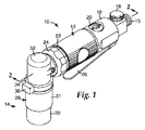
図1は、本開示の表面処理装置10の一実施形態の斜視図である。例示的実施形態では、空気ツール10は、ハンドル部分12及び研磨ヘッド14を包含する。例示的実施形態では、ハンドル部分12は、圧縮空気吸入口15、吸入口調節バルブ16、ハウジング18、バルブプラグ20、キャップロック22、キャップ24、及び手動スロットルレバー26を包含する。研磨ヘッド14は、バンド34で角ハウジング32に取付けられた安定化手段29を包含する。バンド34は、キャップ36で覆われたネジで結合される。安定化手段29は、可動部30、固定部31、及びバネ76(図3a及び3bを参照)を包含する。安定化手段29は、連続的な円筒形のハウジング又は囲い板として示されているものの、他の形状又は非連続形体を使用してもよいことが考慮される。
FIG. 1 is a perspective view of an embodiment of a
例示された実施形態では、ツール10は空気式であり、空気圧縮機(図示せず)に接続される。別の実施形態では、ツール10は、液圧源又は電源などの異なる動力源に接続される。幾つかの実施形態では、ツール10は、それ自体の動力源(電池など)を組み込んでおり、外部動力源への接続を必要としない。
In the illustrated embodiment, the
図2は、図1の線2−2に沿ったツール10の断面図である。操作のために、吸入口15は、圧縮空気源(図示せず)などの動力源に取付けられる。バルブ16は、効果的な吸入口開口部を調節するために使用されてもよい。スロットルレバー26は、バネピン38を中心として枢動可能である。スロットルレバー26を押すと、スロットルバルブ40が上方移動し、バネ42の圧縮が生じ、それによって空気調整器44を通る空気流動が可能になる。圧縮空気は、ギア48と連結したロータ46などの運動発生デバイスの回転を引き起こして、ジャーナル軸受52上のおよそ軸線A−Aにおけるシャフト50の回転を生じさせる。バルブ16を通って流動する空気量を変えると、ロータ46の速度が変化する。研磨ヘッド14の末端部には、研磨ディスク72がある。ツール10は、典型的には研磨ディスク72を3,000〜20,000回転/分、更に典型的には7,500〜10,000回転/分の速度で軌道運動させる。
FIG. 2 is a cross-sectional view of the
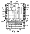
図3aは、非係合位置にあるツール10の研磨ヘッド14の一実施形態の拡大断面図である。更に詳細に示すように、研磨ヘッド14の例示的実施形態は、ネジ58で取付けられた平衡器56を包含する。第2シャフト60の軸線B−Bは、玉軸受62及び64とともに動く。軸線B−Bは、軸線A−A(図2を参照)に対して平行であるが、研磨ディスク72の軌道運動中に軸線A−Aから離れていてもよい。例示的実施形態では、第2シャフト60は、軸線A−Aの周りを旋回する。一実施形態では、軸線B−Bの軸線A−Aからの最大変位は、約1.5mmである。
FIG. 3a is an enlarged cross-sectional view of one embodiment of the polishing
平衡器56は、軸線A−Aの周りの第2シャフト60の旋回を生じさせるのに役立つ。第2シャフト60の回転の速度は、ツールに加えられる力の量、工作物の材料組成及びトポグラフィー、及び使用される研磨材などのパラメーターに依存する場合がある。例えば、非常に小さい圧力の下では、第2シャフト60は比較的速く旋回することがあるのに対して、非常に大きい負荷の下では、第2シャフト60が比較的にゆっくりと旋回することがある。
The
一実施形態では、受け板66は、ネジ68で研磨ヘッド14の末端部に取付けられる。受け板66は、典型的には力制御デバイス74を取付けるための力制御デバイス取付け手段70を包含する。力制御デバイス74は、多数の異なる方法で受け板66に固着されてもよい。例えば、感圧接着剤(PSA)(例えば米国特許第3,849,949号(シュタインハウザー(Steinhauser))ら)を参照)、受け板上の多数のフック部分及び力制御デバイス上の多数のループ部分などの相互係合締結具部材(例えば米国特許第4,609,581号(オット(Ott)を参照)、及び共働する雄型及び雌型の締結具部材を使用することができる。別の好適な取付けシステムは、同一出願人による米国特許第6,988,941号、名称「研磨材バックアップパッド用の係合組立品(Engaging assembly for abrasive back-up pad)」に開示されており、参考として本明細書に組み込まれる。例示された実施形態では、バックアップパッド73及び研磨ディスク72は、順に力制御デバイス74に取付けられる。
In one embodiment, the
例示された実施形態では、スカート28は、角ハウジング32及び受け板66に取付けられて、研磨ディスク72の回転を防止し、それによって研磨ディスク72の軌道運動を生じさせる。別の実施形態では、スカート28が省略されてもよく、そのときはツール10がランダム軌道運動を示すことになる。ランダム軌道運動ツールの一般的な操作原理は、同一出願人による米国特許第5,377,455号、名称「自動ランダム軌道運動研磨システム及び方法(Aumated random orbital abrading system and method)及び同第4,660,329号、名称「動力付き研磨ツール(Poweredl)」に更に記載されており、その両方の内容が参考として本明細書に組み込まれる。本開示の教示を使用したツールは、回転運動、直線運動、又は振動運動など、他のタイプの運動も使用してもよいことが考慮される。
In the illustrated embodiment, the
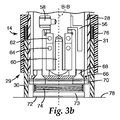
図3aは、非係合位置にあるツール10を示す。この位置では、安定化手段29のバネ76は弛緩している。安定化手段29の可動部30の底面は、研磨ディスク72の下方に延在している。図3bは、係合位置にあるツール10の研磨ヘッド14の拡大断面図である。この位置が実現されるのは、ツールの操作者が安定化手段29の可動部30を工作物表面78に押し付け、それによってバネ76を圧縮させて、研磨ディスク72を工作物表面78と接触させるときである。安定化手段29において、可動部30及び固定部31が、ピンの使用などの手段によって滑動可能に接続されている。
FIG. 3a shows the
例示されるように、力制御デバイス74は、安定化手段29と協働するようにバネで機械的に調整されている。たとえ操作者が必要以上の圧力を加えたとしても、安定化手段29及び力制御デバイス74は、その構造によって、研磨ディスク72を過度の力で工作物表面78と接触させないように構築されている。それ故、安定化手段29及び力制御デバイス74は協働して、研磨ディスク72と工作物表面78との間の接触力が設定レベルを上回るのを防止する。一実施形態では、力制御デバイス74は、最大力制御レベルを有し、設定レベルは、最大力制御レベルよりも小さい。
As illustrated, the
幾つかの実施形態では、安定化手段のバネは、力制御デバイスを超える力を加える。例示的実施形態では、安定化手段のバネは、設定レベルに等しい約22.2N(5ポンドの力)を加えてもよく、一方で、力制御デバイスのバネは、約13.3N(3ポンドの力)を加えてもよい。この構成によって、研磨ディスクと工作物表面との間の全面的な接触(即ち、研磨ディスクのかなりの部分が工作物と接触すること)を確実にし、また、たとえ安定化手段のバネが完全に圧縮されていなくても、所望の圧力(即ち、「設定レベル」)が工作物表面に伝達されるのを確実にする。 In some embodiments, the stabilizing means spring applies a force that exceeds the force control device. In an exemplary embodiment, the stabilizing means spring may apply approximately 22.2 N (5 pounds force) equal to the set level, while the force control device spring is approximately 13.3 N (3 pounds). Power). This arrangement ensures full contact between the abrasive disc and the workpiece surface (ie, a significant portion of the abrasive disc is in contact with the workpiece), and even if the stabilizing means spring is completely Ensures that the desired pressure (ie, “set level”) is transmitted to the workpiece surface, even if not compressed.
別の実施形態では、安定化手段のバネは、力制御デバイスに等しいか、又は力制御デバイスを超える力を加える。図3bは、力制御デバイスを超える力を示す、安定化手段のバネを有する例示的実施形態を示している。図3bに示した係合位置においては、バネ76は、完全に圧縮されており、一方で、力制御デバイス74のバネは、幾分か圧縮されるが完全には圧縮されていない。バネ76が完全に圧縮された地点において、追加の力が操作者によって加えられても、研磨ディスク72と工作物表面78との間の境界面に伝達することはできない。それ故、安定化手段29及び力制御デバイス74は協働して、研磨ディスク72と工作物表面78との間の接触力がそのレベルを上回るのを防止する。
In another embodiment, the spring of the stabilizing means applies a force equal to or exceeding the force control device. FIG. 3b shows an exemplary embodiment with a stabilizing means spring that exhibits a force beyond the force control device. In the engaged position shown in FIG. 3b, the
幾つかの実施形態では、安定化手段は、ツールに関して固定され、バネを備えていない。使用していないとき、力制御デバイスは研磨ディスクが安定化手段を越えて延びるように位置付けられる。使用中においては、固定された安定化手段は、力制御デバイスのバネ(又は他の力制御手段)が完全に圧縮されるのを防止し、いかなる追加の力が操作者によって加えられても、研磨ディスクと工作物表面との間の境界面に伝達できないようになっている。 In some embodiments, the stabilizing means is fixed with respect to the tool and does not comprise a spring. When not in use, the force control device is positioned so that the abrasive disc extends beyond the stabilizing means. In use, the fixed stabilization means prevents the spring (or other force control means) of the force control device from being fully compressed, and any additional force applied by the operator Transmission to the interface between the abrasive disc and the workpiece surface is prevented.
例示的実施形態では、力制御デバイス74が、一定のばね定数を有するバネを包含する。他の実施形態では、力制御デバイス74は、発泡体、ゴム、ネオプレン、又は弾力特性を有する他の材料から形成されてもよい。例示された実施形態は、機械的に調整された力制御デバイス74を包含するものの、力制御デバイスは、例えば空気圧抵抗を使用して空気圧式に調整するか、又は、オイルバルブを使用して液圧式に調整することもできることが考慮される。
In the exemplary embodiment,
一実施形態では、安定化手段29は、研磨ディスク72を包囲する2部からなる円筒形ハウジングを備える例示的実施形態では、安定化手段29は、ツール10の傾き及び工作物表面78への研磨ディスク72の不均一な適用を防止する。代表的な実施形態では、安定化手段29は、それ自体は工作物表面78に掻き傷ないしは別の方法で損傷を与えない、ゴム又はプラスチックなどの材料で作製される。安定化手段29の例示された機構は、バネ76で設定レベルに機械的に調整されるものの、安定化手段29が、例えば空気圧式に又は液圧式に制御されるデバイスであってもよいことも考慮される。
In one embodiment, the stabilizing
例示された実施形態は、力制御デバイス74に取付けられたバックアップパッド73、及びバックアップパッド73に順に取付けられた研磨ディスク72を包含する。取付けの形態は、力制御取付け手段70に関して記載されたものと同一であるか、又は異なり得る。
The illustrated embodiment includes a
バックアップパッド73は、圧縮可能な弾性の材料から構成されてもよく、例えば、所望の硬さ、適合性、及び他の特性に応じて、ビニル、布、開放気泡又は独立気泡ポリマーフォーム(柔軟な独立気泡ネオプレンフォーム、開放気泡ポリエステルフォーム、ポリウレタンフォーム、網目状又は非網状スラブストックフォームなど)などの発泡体、ゴム、又は多孔質熱可塑性ポリマーが挙げられるが、これらに限定されない。典型的なポリウレタン系フォームとしては、トルエンジイソシアネート(TDI)系フォーム及びメチレンジ(又はビス)フェニルジイソシアネート(MDI)系フォームが挙げられる。より柔軟であり、及び/又はより厚いバックアップパッド73は、より微細な仕上げ及び表面の曲線又は工作物表面78の不ぞろいに対してより良好な適合を生じさせることができる。別の実施形態では、バックアップパッド73が除外されてもよく、研磨ディスク72が力制御デバイス74に直接的に取付けられてもよい。
The
研磨ディスク72のための好適な例示的研磨物品は、同一出願人による米国特許第6,231,629号の名称「ガラス上の透明な表面仕上げを提供するための研磨物品(Abrasive article for providing a clear surface finish on glass)」、同第6,312,484号、名称「不織研磨物品及びその作製方法(Nonwoven abrasive articles and method of preparing same)」、及び同第5,454,844号、名称「研磨物品、その製造方法、及び工作物表面を仕上げるためのその使用方法(Abrasive article, a process of making same, and a method of using saminish a workpiece sure)」に開示されており、全てが参考として本明細書に組み込まれる。の好適な研磨ディスクは、スリーエム・カンパニー(3M Company)(ミネソタ州セントポール(St. Paul))から販売名「トライザクト(Trizact)」及び「フィネッセ・イット(Finesse-it)」で市販される。
A suitable exemplary abrasive article for the
幾つかの用途では、サンディングした箇所がその後のバフ研磨をあまり必要としないように、小さな研磨ディスク72を使用するのが望ましい。施形態では、研磨ディスク72は、直径12.7mm(0.5インチ)〜25.4mm(1.0インチ)をする円形又は帆立貝状縁部のディスクである。
In some applications, it may be desirable to use a small
図4は、潤滑剤の塗布及び除去のためのホースを包含する、本開示のツールの実施形態の斜視図である。一実施形態では、ツール10は、潤滑剤塗布ホース80及び真空ホース82を包含する。潤滑剤塗布ホース80は、適正な量のサンディング潤滑剤、例えば水を塗布して、研磨ディスク72が工作物表面78からの研磨済み材料で山積みになるのを防ぐ。山積みになった研磨表面は効果が低いため、これは望ましいのである。一実施形態では、安定化手段29に圧力が加えられるとき、潤滑剤塗布デバイスは、研磨表面72又は工作物表面78に潤滑剤を塗布する。
FIG. 4 is a perspective view of an embodiment of the tool of the present disclosure including a hose for lubricant application and removal. In one embodiment, the
例示された実施形態は、研磨中又は研磨後に研磨残留物及び/又は潤滑剤を除去するために、吸引又は真空ホース82を通じて作用する真空デバイスを包含する。このような残留物又は潤滑剤が除去されなければ、その後に使用されるバフ研磨パッドを汚す可能性があり、それによってバフ研磨プロセス中に不必要な掻き傷を潜在的に生じさせる。
The illustrated embodiment includes a vacuum device that acts through a suction or
図5aは、オン/オフのスイッチ84を包含する、「オフ」位置にあるツールの研磨ヘッドの一実施形態の拡大断面図である。図5bは、「オン」位置にある図5aの研磨ヘッドの拡大断面図である。ツール10の操作を制御するために、スイッチ84が、スロットルレバー26に加えて、又はスロットルレバー26の代わりに使用されてもよい。図5aに例示された「オフ」位置では、スイッチ84は、バネ76の上方で休止しており、スイッチ84のピン83は、安定化手段29の静止部分31の凹部85から外れている。(図5bに示すように)ツールの操作者が安定化手段29の可動部31を工作物表面78に押し付けるとき、バネ76及びスイッチ84が押し上げられ、それによってピン83を凹部85に押し込む。図5bの「オン」位置では、スイッチ84のピン83は、凹部85内に完全に挿入されており、それによってスイッチ84を活性化して研磨ディスク72を動かす。
FIG. 5 a is an enlarged cross-sectional view of one embodiment of the polishing head of the tool in the “off” position, including an on / off
一実施形態では、研磨ディスク72は、スイッチ84が活性化されている間は動く。別の実施形態では、スイッチ84は、研磨ディスク72を指定された時間、例えば約3秒間にわたって自動的に操作し動くタイマー、コンピュータ、又は他の処理装置に接続される。更に多くの操作者の制御が望ましい場合は、代わりに表示灯又は可聴ブザーを使用して、指定された時間が経過したことを操作者に警告することができる。
In one embodiment, the
例示的実施形態では、安定化手段29の可動部30は、欠陥標定機としても働く。可動部30を用いて工作物表面78上の欠陥を包囲することで、操作者は確信を持って欠陥を処理することができる。例示的実施形態では、可動部30は透明な材料から形成されており、これにより、操作者は可動部30を透かし見て、研磨されるべき領域内に工作物の欠陥があることを確認することができる。
In the exemplary embodiment, the
単に回転運動に関する場合は、研磨ディスク72の領域は、可動部30内の領域とほぼ同じであってもよい。軌道運動、ランダム軌道運動、又は他の運動に関する場合、研磨ディスク72の領域は、可動部30内の領域より小さくてもよい。他の実施形態では、欠陥標定機は例えば、工作物表面78上に投影される光又はレーザー画像の形態で提供されてもよい。
In the case of merely rotational movement, the area of the
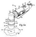
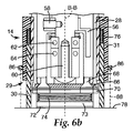
図6aは投影光式欠陥標定機86を包含する、本開示のツール10の実施形態の斜視図である。図6bは、図6aの研磨ヘッド14の拡大断面図である。例示された実施形態では、欠陥標定機86は、安定化手段29に取付けられる。欠陥標定機86は、可視光線パターン88を工作物表面78上に投影する。別の実施形態では、可視光線パターン88は、安定化手段29の可動部30内部から投影される。可視光線パターン88の内の欠陥90を位置付けすることにより、操作者は、確信を持って欠陥90を研磨ディスク72で研磨することができる。可視光線パターン88は、的又は交差する十字線など、他の形状を有することもできる。
FIG. 6 a is a perspective view of an embodiment of the
本明細書で参照又は引用される全ての特許、特許出願、仮出願、及び公報は、本明細書が明白に教示することと矛盾をしない範囲で、全ての図及び表を包含するその全てが参照として組み込まれる。 All patents, patent applications, provisional applications, and publications referenced or cited herein, including all figures and tables, are consistent with the teachings of this specification. Incorporated as a reference.
本明細書に記載される実施例及び実施形態は、単に例示することが目的であり、その種々の変更又は変形が当業者に提示され、本出願の精神及び範囲内に包含されることを理解されるべきである。例えば、ツール10は、角度付きツールとして例示されているものの、ツール10は手持ち式ツールであってもよいこともまた考慮される。加えて、ツール10は、幾つかの実施形態では手持ち式ツールとして記載されているものの、ツール10は、ロボット式に、ないしは別の方法で自動的に操作されてもよいこともまた考慮される。
It is understood that the examples and embodiments described herein are for illustrative purposes only and that various modifications or variations thereof are presented to those skilled in the art and are encompassed within the spirit and scope of this application. It should be. For example, although the
Claims (20)
研磨ディスクを動かすように構成された運動発生デバイスと、
安定化手段と、
力制御デバイスと、を備え、前記安定化手段及び前記力制御デバイスは協働して、前記研磨ディスクと前記工作物表面との間の接触力が設定レベルを上回るのを防止する、表面処理装置。 A surface treatment apparatus for polishing a workpiece surface, the apparatus comprising:
A motion generating device configured to move the abrasive disc;
Stabilizing means;
A surface treatment apparatus comprising: a force control device, wherein the stabilizing means and the force control device cooperate to prevent a contact force between the abrasive disc and the workpiece surface from exceeding a set level. .
固定部及び
可動部を備える、請求項6に記載の表面処理装置。 The stabilizing means
The surface treatment apparatus according to claim 6, comprising a fixed part and a movable part.
Applications Claiming Priority (2)
| Application Number | Priority Date | Filing Date | Title |
|---|---|---|---|
| US11/462,138 US20080032603A1 (en) | 2006-08-03 | 2006-08-03 | Sanding tool |
| PCT/US2007/074547 WO2008016840A1 (en) | 2006-08-03 | 2007-07-27 | Sanding tool |
Publications (2)
| Publication Number | Publication Date |
|---|---|
| JP2009545464A true JP2009545464A (en) | 2009-12-24 |
| JP2009545464A5 JP2009545464A5 (en) | 2010-03-25 |
Family
ID=38997486
Family Applications (1)
| Application Number | Title | Priority Date | Filing Date |
|---|---|---|---|
| JP2009522964A Pending JP2009545464A (en) | 2006-08-03 | 2007-07-27 | Sanding tools |
Country Status (6)
| Country | Link |
|---|---|
| US (1) | US20080032603A1 (en) |
| EP (1) | EP2054194A4 (en) |
| JP (1) | JP2009545464A (en) |
| CN (1) | CN101500752B (en) |
| TW (1) | TW200827094A (en) |
| WO (1) | WO2008016840A1 (en) |
Cited By (4)
| Publication number | Priority date | Publication date | Assignee | Title |
|---|---|---|---|---|
| KR101239733B1 (en) * | 2011-11-22 | 2013-03-06 | 주식회사 대성지티 | Air beveler for narrow gap |
| KR20150020051A (en) * | 2013-08-12 | 2015-02-25 | 더 보잉 컴파니 | Apparatus, system and method for aero-contouring a surface of an aerodynamically functional coating |
| KR101546779B1 (en) * | 2014-03-11 | 2015-08-24 | (주)익산비철 | Rounding and Chamfering device |
| JP2022000323A (en) * | 2020-02-25 | 2022-01-04 | 株式会社ペイントサービス | Air rotary tool for removal of coating film and method for use of air rotary tool |
Families Citing this family (11)
| Publication number | Priority date | Publication date | Assignee | Title |
|---|---|---|---|---|
| US8146194B1 (en) * | 2008-04-07 | 2012-04-03 | James Farrell | Buffing apparatus |
| EP2177314B1 (en) * | 2008-10-20 | 2016-03-23 | X'Pole Precision Tools, Inc. | Ergonomic throttle lever control and hand support |
| DE102008064564A1 (en) | 2008-12-23 | 2010-06-24 | Flex-Elektrowerkzeuge Gmbh | Tool holding head for a hand-held cleaning / grinding machine and hand-held cleaning / grinding machine |
| US10035237B2 (en) * | 2011-11-02 | 2018-07-31 | The Boeing Company | Robotic end effector including multiple abrasion tools |
| WO2014001072A2 (en) * | 2012-06-27 | 2014-01-03 | Atlas Copco Industrial Technique Ab | Power tool and a handle of a pneumatic power tool |
| US9409206B2 (en) * | 2013-05-02 | 2016-08-09 | The Boeing Company | Methods and systems for applying aerodynamically functional coatings to a surface |
| US20150056897A1 (en) * | 2013-08-22 | 2015-02-26 | X'pole Precision Tools Inc. | Sander providing airflow correction |
| DE102013225885A1 (en) * | 2013-12-13 | 2015-06-18 | Robert Bosch Gmbh | Battery operated eccentric sander with a rechargeable battery |
| CN105252125A (en) * | 2015-10-26 | 2016-01-20 | 中国石油天然气集团公司 | Wind-proof device for welding gun |
| KR102116228B1 (en) * | 2016-03-11 | 2020-05-28 | 니토 코키 가부시키가이샤 | Belt grinding tool |
| CN110039420B (en) * | 2018-01-15 | 2024-04-09 | 苏州宝时得电动工具有限公司 | Polishing tool, and method for detaching and installing base plate assembly of polishing tool |
Citations (2)
| Publication number | Priority date | Publication date | Assignee | Title |
|---|---|---|---|---|
| US2922261A (en) * | 1957-04-24 | 1960-01-26 | Samuel J Rabkin | Apparatus for removing surface coatings |
| US5303513A (en) * | 1992-09-22 | 1994-04-19 | Honda Of America Mfg., Inc. | Portable abrading handtool |
Family Cites Families (14)
| Publication number | Priority date | Publication date | Assignee | Title |
|---|---|---|---|---|
| US1653108A (en) * | 1926-04-29 | 1927-12-20 | Koenig Otto Alfred | Surfacing machine |
| US2290533A (en) * | 1942-03-24 | 1942-07-21 | Jr Francis Kavanaugh Campbell | Carbon cleaning brush |
| US3619954A (en) * | 1969-02-07 | 1971-11-16 | Billy G Miller | Surface-treating apparatus and method |
| US4216630A (en) * | 1977-08-25 | 1980-08-12 | The Aro Corporation | Grinder apparatus with pollution control fluid dispensing means |
| US5289605A (en) * | 1991-12-10 | 1994-03-01 | Armbruster Joseph M | DC powered scrubber |
| KR0134955Y1 (en) * | 1996-07-12 | 1998-12-15 | 홍광수 | Apparatus for cutting the receptacles for cultivating the mushroom |
| US6183355B1 (en) * | 1998-09-25 | 2001-02-06 | Walter J. Robinson | Adapter apparatus for sanding, grinding or buffing |
| US6558232B1 (en) * | 2000-05-12 | 2003-05-06 | Multi-Planar Technologies, Inc. | System and method for CMP having multi-pressure zone loading for improved edge and annular zone material removal control |
| CN100433269C (en) * | 2000-05-12 | 2008-11-12 | 多平面技术公司 | Pneumatic diaphragm head having independent retaining ring and multi-region pressure control, and method to use the same |
| DE10347849B4 (en) * | 2003-10-10 | 2016-04-28 | Robert Bosch Gmbh | Exzenterschleifhandwerkzeugmaschine |
| US20050214712A1 (en) * | 2004-02-20 | 2005-09-29 | Farzad Shaygan | Dental stain remover |
| JP4009278B2 (en) * | 2004-06-29 | 2007-11-14 | 株式会社呉英製作所 | Thunder |
| JP2006007402A (en) * | 2004-06-29 | 2006-01-12 | Goei Seisakusho:Kk | Grinding device |
| CN2767056Y (en) * | 2004-10-22 | 2006-03-29 | 江苏省苏美达五金工具有限公司 | Electric tool for sanding or polishing |
-
2006
- 2006-08-03 US US11/462,138 patent/US20080032603A1/en not_active Abandoned
-
2007
- 2007-07-27 JP JP2009522964A patent/JP2009545464A/en active Pending
- 2007-07-27 CN CN2007800288430A patent/CN101500752B/en not_active Expired - Fee Related
- 2007-07-27 WO PCT/US2007/074547 patent/WO2008016840A1/en active Application Filing
- 2007-07-27 EP EP07799871A patent/EP2054194A4/en not_active Withdrawn
- 2007-08-02 TW TW096128423A patent/TW200827094A/en unknown
Patent Citations (2)
| Publication number | Priority date | Publication date | Assignee | Title |
|---|---|---|---|---|
| US2922261A (en) * | 1957-04-24 | 1960-01-26 | Samuel J Rabkin | Apparatus for removing surface coatings |
| US5303513A (en) * | 1992-09-22 | 1994-04-19 | Honda Of America Mfg., Inc. | Portable abrading handtool |
Cited By (6)
| Publication number | Priority date | Publication date | Assignee | Title |
|---|---|---|---|---|
| KR101239733B1 (en) * | 2011-11-22 | 2013-03-06 | 주식회사 대성지티 | Air beveler for narrow gap |
| KR20150020051A (en) * | 2013-08-12 | 2015-02-25 | 더 보잉 컴파니 | Apparatus, system and method for aero-contouring a surface of an aerodynamically functional coating |
| JP2015061735A (en) * | 2013-08-12 | 2015-04-02 | ザ・ボーイング・カンパニーTheBoeing Company | Apparatus, system and method for aero-contouring surface of aerodynamically functional coating |
| KR102152477B1 (en) * | 2013-08-12 | 2020-09-07 | 더 보잉 컴파니 | Apparatus, system and method for aero-contouring a surface of an aerodynamically functional coating |
| KR101546779B1 (en) * | 2014-03-11 | 2015-08-24 | (주)익산비철 | Rounding and Chamfering device |
| JP2022000323A (en) * | 2020-02-25 | 2022-01-04 | 株式会社ペイントサービス | Air rotary tool for removal of coating film and method for use of air rotary tool |
Also Published As
| Publication number | Publication date |
|---|---|
| TW200827094A (en) | 2008-07-01 |
| WO2008016840A1 (en) | 2008-02-07 |
| US20080032603A1 (en) | 2008-02-07 |
| EP2054194A1 (en) | 2009-05-06 |
| CN101500752A (en) | 2009-08-05 |
| CN101500752B (en) | 2011-04-13 |
| EP2054194A4 (en) | 2012-09-26 |
Similar Documents
| Publication | Publication Date | Title |
|---|---|---|
| JP2009545464A (en) | Sanding tools | |
| US6102777A (en) | Lapping apparatus and method for high speed lapping with a rotatable abrasive platen | |
| US6149506A (en) | Lapping apparatus and method for high speed lapping with a rotatable abrasive platen | |
| US5967882A (en) | Lapping apparatus and process with two opposed lapping platens | |
| US5910041A (en) | Lapping apparatus and process with raised edge on platen | |
| US5993298A (en) | Lapping apparatus and process with controlled liquid flow across the lapping surface | |
| US6120352A (en) | Lapping apparatus and lapping method using abrasive sheets | |
| US6048254A (en) | Lapping apparatus and process with annular abrasive area | |
| US6234886B1 (en) | Multiple abrasive assembly and method | |
| JP4287093B2 (en) | Improvement of polishing disc | |
| US6261164B1 (en) | Multiple abrasive assembly and method | |
| US8172650B2 (en) | Automatic shift dual-action tool | |
| EP0868976A2 (en) | Lapping apparatus and method for high speed lapping with a rotatable abrasive platen | |
| JPH0585543U (en) | Automatic control random orbit polishing machine | |
| JPH0852648A (en) | Vibrating hand tool driven with two functions | |
| AU7478598A (en) | Apparatus and method for cleaning and finishing | |
| JP5712290B2 (en) | Plate locking mechanism | |
| WO2002006010A9 (en) | Polishing device | |
| US4986036A (en) | Abrading or polishing tool | |
| EP2262613B1 (en) | Method, apparatus, and system using adapter assembly for modifying surfaces | |
| US3307300A (en) | Abrasive disk unit | |
| US3900976A (en) | Device for supporting a coated abrasive | |
| JP3894693B2 (en) | Coating defect removal method and coating defect removal polishing machine | |
| JP3664663B2 (en) | Polishing machine for wood surface finishing | |
| CN112041114A (en) | Conformable abrasive article |
Legal Events
| Date | Code | Title | Description |
|---|---|---|---|
| A521 | Request for written amendment filed |
Free format text: JAPANESE INTERMEDIATE CODE: A523 Effective date: 20100203 |
|
| A621 | Written request for application examination |
Free format text: JAPANESE INTERMEDIATE CODE: A621 Effective date: 20100203 |
|
| A131 | Notification of reasons for refusal |
Free format text: JAPANESE INTERMEDIATE CODE: A131 Effective date: 20120807 |
|
| A02 | Decision of refusal |
Free format text: JAPANESE INTERMEDIATE CODE: A02 Effective date: 20130108 |
