JP2009544865A - Impregnated inorganic paper and method for producing the same - Google Patents
Impregnated inorganic paper and method for producing the same Download PDFInfo
- Publication number
- JP2009544865A JP2009544865A JP2009521767A JP2009521767A JP2009544865A JP 2009544865 A JP2009544865 A JP 2009544865A JP 2009521767 A JP2009521767 A JP 2009521767A JP 2009521767 A JP2009521767 A JP 2009521767A JP 2009544865 A JP2009544865 A JP 2009544865A
- Authority
- JP
- Japan
- Prior art keywords
- impregnated
- inorganic material
- paper
- mica paper
- impregnating
- Prior art date
- Legal status (The legal status is an assumption and is not a legal conclusion. Google has not performed a legal analysis and makes no representation as to the accuracy of the status listed.)
- Pending
Links
Images


Classifications
-
- B—PERFORMING OPERATIONS; TRANSPORTING
- B32—LAYERED PRODUCTS
- B32B—LAYERED PRODUCTS, i.e. PRODUCTS BUILT-UP OF STRATA OF FLAT OR NON-FLAT, e.g. CELLULAR OR HONEYCOMB, FORM
- B32B29/00—Layered products comprising a layer of paper or cardboard
- B32B29/06—Layered products comprising a layer of paper or cardboard specially treated, e.g. surfaced, parchmentised
-
- D—TEXTILES; PAPER
- D21—PAPER-MAKING; PRODUCTION OF CELLULOSE
- D21H—PULP COMPOSITIONS; PREPARATION THEREOF NOT COVERED BY SUBCLASSES D21C OR D21D; IMPREGNATING OR COATING OF PAPER; TREATMENT OF FINISHED PAPER NOT COVERED BY CLASS B31 OR SUBCLASS D21G; PAPER NOT OTHERWISE PROVIDED FOR
- D21H17/00—Non-fibrous material added to the pulp, characterised by its constitution; Paper-impregnating material characterised by its constitution
- D21H17/63—Inorganic compounds
- D21H17/67—Water-insoluble compounds, e.g. fillers, pigments
- D21H17/68—Water-insoluble compounds, e.g. fillers, pigments siliceous, e.g. clays
-
- B—PERFORMING OPERATIONS; TRANSPORTING
- B32—LAYERED PRODUCTS
- B32B—LAYERED PRODUCTS, i.e. PRODUCTS BUILT-UP OF STRATA OF FLAT OR NON-FLAT, e.g. CELLULAR OR HONEYCOMB, FORM
- B32B17/00—Layered products essentially comprising sheet glass, or glass, slag, or like fibres
- B32B17/06—Layered products essentially comprising sheet glass, or glass, slag, or like fibres comprising glass as the main or only constituent of a layer, next to another layer of a specific material
- B32B17/067—Layered products essentially comprising sheet glass, or glass, slag, or like fibres comprising glass as the main or only constituent of a layer, next to another layer of a specific material of fibres or filaments
-
- B—PERFORMING OPERATIONS; TRANSPORTING
- B32—LAYERED PRODUCTS
- B32B—LAYERED PRODUCTS, i.e. PRODUCTS BUILT-UP OF STRATA OF FLAT OR NON-FLAT, e.g. CELLULAR OR HONEYCOMB, FORM
- B32B5/00—Layered products characterised by the non- homogeneity or physical structure, i.e. comprising a fibrous, filamentary, particulate or foam layer; Layered products characterised by having a layer differing constitutionally or physically in different parts
- B32B5/02—Layered products characterised by the non- homogeneity or physical structure, i.e. comprising a fibrous, filamentary, particulate or foam layer; Layered products characterised by having a layer differing constitutionally or physically in different parts characterised by structural features of a fibrous or filamentary layer
-
- B—PERFORMING OPERATIONS; TRANSPORTING
- B32—LAYERED PRODUCTS
- B32B—LAYERED PRODUCTS, i.e. PRODUCTS BUILT-UP OF STRATA OF FLAT OR NON-FLAT, e.g. CELLULAR OR HONEYCOMB, FORM
- B32B5/00—Layered products characterised by the non- homogeneity or physical structure, i.e. comprising a fibrous, filamentary, particulate or foam layer; Layered products characterised by having a layer differing constitutionally or physically in different parts
- B32B5/22—Layered products characterised by the non- homogeneity or physical structure, i.e. comprising a fibrous, filamentary, particulate or foam layer; Layered products characterised by having a layer differing constitutionally or physically in different parts characterised by the presence of two or more layers which are next to each other and are fibrous, filamentary, formed of particles or foamed
- B32B5/24—Layered products characterised by the non- homogeneity or physical structure, i.e. comprising a fibrous, filamentary, particulate or foam layer; Layered products characterised by having a layer differing constitutionally or physically in different parts characterised by the presence of two or more layers which are next to each other and are fibrous, filamentary, formed of particles or foamed one layer being a fibrous or filamentary layer
- B32B5/28—Layered products characterised by the non- homogeneity or physical structure, i.e. comprising a fibrous, filamentary, particulate or foam layer; Layered products characterised by having a layer differing constitutionally or physically in different parts characterised by the presence of two or more layers which are next to each other and are fibrous, filamentary, formed of particles or foamed one layer being a fibrous or filamentary layer impregnated with or embedded in a plastic substance
-
- B—PERFORMING OPERATIONS; TRANSPORTING
- B32—LAYERED PRODUCTS
- B32B—LAYERED PRODUCTS, i.e. PRODUCTS BUILT-UP OF STRATA OF FLAT OR NON-FLAT, e.g. CELLULAR OR HONEYCOMB, FORM
- B32B7/00—Layered products characterised by the relation between layers; Layered products characterised by the relative orientation of features between layers, or by the relative values of a measurable parameter between layers, i.e. products comprising layers having different physical, chemical or physicochemical properties; Layered products characterised by the interconnection of layers
- B32B7/04—Interconnection of layers
- B32B7/12—Interconnection of layers using interposed adhesives or interposed materials with bonding properties
-
- D—TEXTILES; PAPER
- D21—PAPER-MAKING; PRODUCTION OF CELLULOSE
- D21H—PULP COMPOSITIONS; PREPARATION THEREOF NOT COVERED BY SUBCLASSES D21C OR D21D; IMPREGNATING OR COATING OF PAPER; TREATMENT OF FINISHED PAPER NOT COVERED BY CLASS B31 OR SUBCLASS D21G; PAPER NOT OTHERWISE PROVIDED FOR
- D21H13/00—Pulp or paper, comprising synthetic cellulose or non-cellulose fibres or web-forming material
- D21H13/36—Inorganic fibres or flakes
- D21H13/38—Inorganic fibres or flakes siliceous
- D21H13/40—Inorganic fibres or flakes siliceous vitreous, e.g. mineral wool, glass fibres
-
- D—TEXTILES; PAPER
- D21—PAPER-MAKING; PRODUCTION OF CELLULOSE
- D21H—PULP COMPOSITIONS; PREPARATION THEREOF NOT COVERED BY SUBCLASSES D21C OR D21D; IMPREGNATING OR COATING OF PAPER; TREATMENT OF FINISHED PAPER NOT COVERED BY CLASS B31 OR SUBCLASS D21G; PAPER NOT OTHERWISE PROVIDED FOR
- D21H13/00—Pulp or paper, comprising synthetic cellulose or non-cellulose fibres or web-forming material
- D21H13/36—Inorganic fibres or flakes
- D21H13/38—Inorganic fibres or flakes siliceous
- D21H13/44—Flakes, e.g. mica, vermiculite
-
- D—TEXTILES; PAPER
- D21—PAPER-MAKING; PRODUCTION OF CELLULOSE
- D21H—PULP COMPOSITIONS; PREPARATION THEREOF NOT COVERED BY SUBCLASSES D21C OR D21D; IMPREGNATING OR COATING OF PAPER; TREATMENT OF FINISHED PAPER NOT COVERED BY CLASS B31 OR SUBCLASS D21G; PAPER NOT OTHERWISE PROVIDED FOR
- D21H13/00—Pulp or paper, comprising synthetic cellulose or non-cellulose fibres or web-forming material
- D21H13/36—Inorganic fibres or flakes
- D21H13/46—Non-siliceous fibres, e.g. from metal oxides
- D21H13/50—Carbon fibres
-
- G—PHYSICS
- G02—OPTICS
- G02F—OPTICAL DEVICES OR ARRANGEMENTS FOR THE CONTROL OF LIGHT BY MODIFICATION OF THE OPTICAL PROPERTIES OF THE MEDIA OF THE ELEMENTS INVOLVED THEREIN; NON-LINEAR OPTICS; FREQUENCY-CHANGING OF LIGHT; OPTICAL LOGIC ELEMENTS; OPTICAL ANALOGUE/DIGITAL CONVERTERS
- G02F1/00—Devices or arrangements for the control of the intensity, colour, phase, polarisation or direction of light arriving from an independent light source, e.g. switching, gating or modulating; Non-linear optics
- G02F1/01—Devices or arrangements for the control of the intensity, colour, phase, polarisation or direction of light arriving from an independent light source, e.g. switching, gating or modulating; Non-linear optics for the control of the intensity, phase, polarisation or colour
- G02F1/13—Devices or arrangements for the control of the intensity, colour, phase, polarisation or direction of light arriving from an independent light source, e.g. switching, gating or modulating; Non-linear optics for the control of the intensity, phase, polarisation or colour based on liquid crystals, e.g. single liquid crystal display cells
- G02F1/133—Constructional arrangements; Operation of liquid crystal cells; Circuit arrangements
- G02F1/1333—Constructional arrangements; Manufacturing methods
- G02F1/133305—Flexible substrates, e.g. plastics, organic film
-
- Y—GENERAL TAGGING OF NEW TECHNOLOGICAL DEVELOPMENTS; GENERAL TAGGING OF CROSS-SECTIONAL TECHNOLOGIES SPANNING OVER SEVERAL SECTIONS OF THE IPC; TECHNICAL SUBJECTS COVERED BY FORMER USPC CROSS-REFERENCE ART COLLECTIONS [XRACs] AND DIGESTS
- Y10—TECHNICAL SUBJECTS COVERED BY FORMER USPC
- Y10T—TECHNICAL SUBJECTS COVERED BY FORMER US CLASSIFICATION
- Y10T428/00—Stock material or miscellaneous articles
- Y10T428/24—Structurally defined web or sheet [e.g., overall dimension, etc.]
- Y10T428/24355—Continuous and nonuniform or irregular surface on layer or component [e.g., roofing, etc.]
-
- Y—GENERAL TAGGING OF NEW TECHNOLOGICAL DEVELOPMENTS; GENERAL TAGGING OF CROSS-SECTIONAL TECHNOLOGIES SPANNING OVER SEVERAL SECTIONS OF THE IPC; TECHNICAL SUBJECTS COVERED BY FORMER USPC CROSS-REFERENCE ART COLLECTIONS [XRACs] AND DIGESTS
- Y10—TECHNICAL SUBJECTS COVERED BY FORMER USPC
- Y10T—TECHNICAL SUBJECTS COVERED BY FORMER US CLASSIFICATION
- Y10T428/00—Stock material or miscellaneous articles
- Y10T428/4935—Impregnated naturally solid product [e.g., leather, stone, etc.]
Abstract
特殊な含浸用材料(例えばシルセスキオキサン、SiO2/X2O重量比(XはアルカリNa、Kなどである)が1.6〜3.5であるアルカリケイ酸塩ガラス)を含浸させた細孔/隙間を伴う自立形無機材料(例えば雲母紙、カーボン紙、ガラス繊維紙)から作られる可撓性基板が本明細書で記述される。一実施形態においては、可撓性基板は、(1)自立形無機材料を提供するステップと、(2)含浸用材料を提供するステップと、(3)含浸用材料を自立形無機材料内部の細孔/隙間に含浸させるステップと、および(4)含浸済み細孔/隙間を伴う自立形無機材料を硬化させて可撓性基板を形成させるステップとによって作られる。可撓性基板は典型的には、フレキシブルディスプレイまたは可撓性電子部品を作るのにも用いられる。Impregnating special impregnation material (for example, silsesquioxane, alkali silicate glass having a SiO 2 / X 2 O weight ratio (X is alkali Na, K, etc.) of 1.6 to 3.5) Described herein are flexible substrates made of free-standing inorganic materials (eg, mica paper, carbon paper, glass fiber paper) with open pores / gaps. In one embodiment, the flexible substrate comprises: (1) providing a freestanding inorganic material; (2) providing an impregnating material; and (3) placing the impregnating material within the freestanding inorganic material. Impregnating the pores / gaps and (4) curing the free-standing inorganic material with the impregnated pores / gaps to form a flexible substrate. Flexible substrates are also typically used to make flexible displays or flexible electronic components.
Description
本発明は、含浸済み無機材料およびその製造方法に関する。一実施形態においては、含浸済み無機材料(可撓性基板、含浸済み無機紙)は、フレキシブルディスプレイまたは可撓性電子部品を作るために使用される。 The present invention relates to an impregnated inorganic material and a method for producing the same. In one embodiment, the impregnated inorganic material (flexible substrate, impregnated inorganic paper) is used to make a flexible display or flexible electronic component.
本明細書では略語は以下のように定義づけされ、以下の記述においてはその少なくとも一部分が言及されることになる。 In the present specification, abbreviations are defined as follows, and at least a part thereof will be referred to in the following description.
Al アルミニウム
CTE 熱膨張係数
IPA イソプロピルアルコール
ITO イソジウムスズ酸化物
LCD 液晶ディスプレイ
OLED 有機発光ダイオード
PC ポリカーボネート
PEN ポリエチレンナフタレート
PES ポリエーテルスルホン
RH 相対湿度
RFID 高周波識別
SEM 走査電子顕微鏡法
UV 紫外線
今日、フレキシブルディスプレイ(例えば電気泳動ディスプレイ、コレステリック液晶ディスプレイ、OLEDディスプレイ、LCDディスプレイ)および可撓性電子部品(例えば光起電力技術、太陽電池、RFID、センサー)に付随する利用分野においては、改善された耐久性、重量および曲げ半径を有する低コスト可撓性基板に対する必要性が存在する。例えば、アクティブマトリクス駆動ディスプレイの製造に適したものである寸法的安定性、所望のCTE、靭性、透明度、加熱能力およびバリア特性/密封性を有する可撓性基板が求められている。現在、無充填の熱可塑性物質(PEN、PES、PC…)の基板、金属(ステンレス鋼)基板および薄いガラス基板が、これらの利用分野のために使用されている。
Al Aluminum CTE Coefficient of Thermal Expansion IPA Isopropyl Alcohol ITO Isodium Tin Oxide LCD Liquid Crystal Display OLED Organic Light Emitting Diode PC Polycarbonate PEN Polyethylene Naphthalate PES Polyethersulfone RH Relative Humidity RFID High Frequency Identification SEM Scanning Electron Microscopy UV Ultraviolet Improved durability, weight and bending in applications associated with electrophoretic displays, cholesteric liquid crystal displays, OLED displays, LCD displays) and flexible electronic components (eg photovoltaic technology, solar cells, RFID, sensors) There is a need for a low cost flexible substrate having a radius. For example, there is a need for a flexible substrate having dimensional stability, desired CTE, toughness, transparency, heating capability and barrier properties / sealing properties that are suitable for the manufacture of active matrix driven displays. Currently, unfilled thermoplastic (PEN, PES, PC ...), metal (stainless steel) and thin glass substrates are used for these applications.
しかしながらプラスチック基板自体には、低いO2および水蒸気バリア特性、比較的高いCTE、寸法的安定性、熱限界および化学的耐久性という欠点がある。これに対し、金属基板には、表面粗度、非透明性、および伝導性という欠点があり、一方薄いガラス基板は、脆性で亀裂に敏感であり、従って曲げおよび切断に問題がある。本発明の1つの主要な目的は、プラスチック基板、金属基板および連続的薄ガラス基板の特性と比べた場合に改善された物理的特性を有する可撓性基板を提供することにある。この必要性およびその他の必要性は、本発明の可撓性基板および方法によって満たされる。 However, the plastic substrate itself has the disadvantages of low O 2 and water vapor barrier properties, relatively high CTE, dimensional stability, thermal limits and chemical durability. In contrast, metal substrates have the disadvantages of surface roughness, non-transparency, and conductivity, while thin glass substrates are brittle and sensitive to cracks and therefore have problems with bending and cutting. One principal object of the present invention is to provide a flexible substrate having improved physical properties when compared to those of plastic substrates, metal substrates and continuous thin glass substrates. This need and other needs are met by the flexible substrate and method of the present invention.
特殊な含浸用材料(例えばシルセスキオキサン、SiO2/X2O重量比(XはアルカリNa、Kなどである)が1.6〜3.5であるアルカリケイ酸塩ガラス)を含浸させた細孔/隙間を伴う自立形無機材料(例えば雲母紙)から作られる可撓性基板が本明細書で記述される。一実施形態においては、可撓性基板は、(1)自立形無機材料を提供するステップと、(2)含浸用材料を提供するステップと、(3)含浸用材料を自立形無機材料内部の細孔/隙間に含浸させるステップと、および(4)含浸済み細孔/隙間を伴う自立形無機材料を硬化させて可撓性基板を形成させるステップとによって作られる。可撓性基板は典型的には、フレキシブルディスプレイまたは可撓性電子部品を作るのにも用いられる。 Impregnating special impregnation material (for example, silsesquioxane, alkali silicate glass having a SiO 2 / X 2 O weight ratio (X is alkali Na, K, etc.) of 1.6 to 3.5) Described herein are flexible substrates made of free-standing inorganic material (eg, mica paper) with open pores / gaps. In one embodiment, the flexible substrate comprises: (1) providing a freestanding inorganic material; (2) providing an impregnating material; and (3) placing the impregnating material within the freestanding inorganic material. Impregnating the pores / gaps and (4) curing the free-standing inorganic material with the impregnated pores / gaps to form a flexible substrate. Flexible substrates are also typically used to make flexible displays or flexible electronic components.
本発明は、添付図面と合わせて以下の詳細な記述を参照することによってより完全に理解することができる。 The present invention can be more fully understood by reference to the following detailed description in conjunction with the accompanying drawings.
図1は、本発明の一実施形態に従った可撓性基板100(含浸済み無機材料100)の横断側面図である。可撓性基板100は、特殊な含浸用材料106が含浸された隙間/細孔104を伴う自立形無機材料102(自立形無機紙102)を含む。望ましい場合には、可撓性基板100は、バリア特性の改善を助けるため一方の表面または両方の表面上に設置されたバリアコーティング108を有することができる。例えば、バリアコーティング108は、被着された無機層(例えばシリカ、窒化ケイ素…)、多層無機/有機層スタック(例えば、バイテックス・システムズ(Vitex Systems)製バリックス(Barix)(商標)コーティング…)または連続的薄型有機シート(例えばコーニング(Corning)のマイクロシート(Micro sheet))であり得る。
FIG. 1 is a cross-sectional side view of a flexible substrate 100 (impregnated inorganic material 100) according to one embodiment of the present invention. The
自立形無機材料102は、結晶質または非結晶質のいずれかである無機材料から成る粒子(または繊維)の集合である。例えば、自立形無機材料102は、雲母紙102、グラファイト紙102、カーボンナノチューブ紙102またはガラス繊維紙102であってよい。一般に、特定の利用分野のために用いるべく選択される自立形無機材料102のタイプは、例えば材料組成、機械的特性、細孔体積、粒径、アスペクト比および光吸収を含めたいくつかの物理的特性に基づいている。さらに、自立形無機材料102は、フレキシブルディスプレイ(例えば電気泳動ディスプレイ、コレステリック液晶ディスプレイ、OLEDディスプレイ、LCDディスプレイ、その他の能動または受動マトリクスディスプレイおよび駆動回路)または可撓性電子部品(例えば光起電力技術、太陽電池、RFID、センサー)などといった、製造を補助することになるデバイスのタイプに基づいて選択される。
The free-standing
含浸用材料106は、一部には自立形無機材料102内部の細孔/隙間104にそれがいかにうまく含浸できるかに基づいて選択される。例えば、自立形無機材料102の内部の細孔/隙間104に含浸するように用いられた本明細書で開示されている含浸用材料106の2つのタイプには、ゾル−ゲルシルセスキオキサン材料106およびケイ酸カリウムガラス106(ここでケイ酸カリウムガラスは2.5というSiO2/K2O重量比を有する)が含まれる。ただし、その材料が自立形無機材料102の内部の細孔/隙間104に有効に含浸できるかぎり、その他のタイプの含浸用材料を代りに使用することも可能である。さらに、含浸用材料106は、一部には、フレキシブルディスプレイおよび/または可撓性電子部品を製造するのに使用できるようにそれが所望の物理的特性をもつ可撓性基板を作ることができるか否かに基づいて選択される。表1は、フレキシブルディスプレイおよび/または可撓性電子部品を製造するのに使用できるように例示的可撓性基板100が示した所望の物理的特性の一覧表を含んでいる。

一実施形態においては、可撓性基板100は、自立形雲母紙102とゾル−ゲルシルセスキオキサン含浸用材料106から作られる。シルセスキオキサン含浸用材料106は、(例えば)以下のものを含めたさまざまな理由で使用するべく選択された:
1.シルセスキオキサン含浸用材料106は、予備形成された雲母紙102の細孔/隙間104に有効に浸潤でき、かくして低多効率できわめて無機性の高い複合可撓性材料100を作ることができる。
2.シルセスキオキサン含浸用材料106を用いて、より低温のシリコーンまたは重合体含浸用材料を使用した場合よりも密度の高いマトリクスを有する可撓性基板100を作ることができる。
3.シルセスキオキサン含浸用材料106から、有機含浸用材料を使用した場合よりも高い加熱能力を有する可撓性基板100が作られる。
4.シルセスキオキサン含浸用材料106は、収縮亀裂または開放細孔率を最小限におさえる加工を可能にする最低の収縮および最低の質量損失をもつ穏やかな熱処理を使用して熱硬化できるシルセスキオキサンの加水分解された樹脂を作ることができるという点で、加工可能性が高い。
5.シルセスキオキサン含浸用材料106は、可視スペクトル内で1.40<n<1.60の範囲にわたって変動し得る屈折率を有し、そのため、ガラス繊維紙といったような自立形無機材料102との光学的整合を最適化することが可能である。
6.シルセスキオキサン含浸用材料106は加工が容易であり、ガラスといったような完全に無機の含浸材料と比較して低いモジュラス、高い耐ひずみ性を有する。
7.シルセスキオキサン含浸用材料106は、大部分の有機重合体含浸用材料と比較した場合、より優れた熱耐久性、およびより低い温湿度脆弱性を有する。
8.シルセスキオキサン含浸用材料106と雲母紙102の組合せは所望の形状および所望の物理的特性、例えば可撓性、熱耐久性、浸透抵抗性および低いCTEを有する(表1参照)。
9.シルセスキオキサン含浸用材料106は、ガラス(溶融プロセス由来の)、熱分解炭素またはセラミック含浸用材料といったようなその他の材料よりも低い加工温度しか必要としない。
In one embodiment, the
1. The
2. The
3. From the
4). The
5. The
6). The
7). The
8). The combination of
9. The
平面導波路構造を作るために当初使用されたシルセスキオキサン106の組成についての詳細な論述が、以下の共に譲渡された特許の中で提供されている:
・「光透過性固着材料(Optically Transmissive Bonding Material)」という標題の米国特許第5,991,493号明細書、
・「ハイブリッド有機・無機平面光導波路装置(Hybrid Organic−Inorganic Planar Optical Waveguide Device)」という標題の米国特許第6,144,795号明細書、
・「整形された光学素子を伴う光ファイバコンポーネントおよびその作製方法(Optical Fiber Component with Shaped Optical Element and Method of Making Same)」という標題の米国特許第6,488,414B1号明細書、
・「ハイブリッド有機・無機平面光導波路デバイス(Hybrid Organic−Inorganic Planar Optical Waveguide Device)」という標題の米国特許第6,511,615B1号明細書。
A detailed discussion of the composition of
US Pat. No. 5,991,493, entitled “Optically Transmissive Bonding Material”,
US Pat. No. 6,144,795 entitled “Hybrid Organic-Inorganic Planar Optical Waveguide Device”,
US Pat. No. 6,488,414B1, entitled “Optical Fiber Component With Optical Element and Method of Making Same”, with optical fiber component with shaped optical element,
US Pat. No. 6,511,615 B1, entitled “Hybrid Organic-Inorganic Planar Optical Waveguide Device”.
これらの特許は本明細書に参照により援用されている。 These patents are hereby incorporated by reference.
本発明は、組合せ型雲母紙102/シルセスキオキサン含浸用材料106を試験し、結果として得られた可撓性基板100をフレキシブルディスプレイとして使用できるか否かを判定するべく評価した。これらの試験およびその結果についての論述を次に図2A〜2Oに関連して提供する。
The present invention tested the combined
1.実験
1A.雲母紙の特徴
2種の市販の雲母紙102(およびシルセスキオキサン含浸用材料106)を用いて、含浸済み雲母ディスプレイ材料100を作製した。雲母紙102は両方共、USサマイカ社(US Samica Inc.)およびコジェビ社(Cogebi Inc.)により天然雲母源から作られており、両方共、過去において電子産業(例えばコンデンサの利用分野)で誘電層として標準的に使用されてきた。例えば、コジェビ社のコジェキャップ(Cogecap)雲母紙は、焼成ムスコバイト天然雲母から形成されている。これら2つの雲母紙102の基本材料は、表2に提供されている。
2種の雲母紙102は、雲母微粒子サイズおよび厚さ、ひいては脆性が異なっている。ただし、雲母紙102は両方共、水に曝露された場合に構成雲母片へと急速に崩壊する。
The two types of
1B.ゾル−ゲルアプローチおよび材料
2種の市販の雲母紙102の隙間104に含浸させるためにシルセスキオキサン材料106が使用された。シルセスキオキサン材料106は、一般式RSiO3/2により特徴づけされ、この式中Rは、単純なメチル、エチルおよびフェニル基からメタクリレート、エポキシドおよび架橋化合物といったようなさらに複雑で反応性の高い有機基に至る可能性のある有機変性剤である。反応性有機基を選択することにより含浸済み無機紙100の屈折率を変動させ、熱的および化学的耐久性を最適化することができる。シルセスキオキサン材料106は化学的にシリカ(SiO2)とシリコーン(R2SiO)の間にあり、中間的特性を有する。シロキサン網状結合は、3網状Si−O−Si結合を伴う変性テトラヘドラを形成することから、シルセスキオキサン材料106の密度は比較的高く、これはシリコーン含浸材料よりも優れた浸透性を導く。典型的には、シルセスキオキサン材料106の測定された密度は、組成に応じて1.3〜1.4g/cm3の範囲内にあった。さらに、シルセスキオキサン材料106は、最小限の収縮/質量損失で硬化され得、このことはすなわち、雲母紙102の内部の小規模の細孔104に含浸するのに適しているということを意味している。
1B. Sol-Gel Approach and Material
当初から、雲母紙102/シルセスキオキサン106の間の熱耐久性および屈折率は、結果として得られる可撓性基板100のための貴重なパラメータであったが、ここで前者のパラメータは重合体含浸用材料との根本的な弁別を提供し、一方後者のパラメータは、結果として得られる可撓性基板100における透明性を可能にする。メチルおよびフェニルシルセスキオキサン前駆体の組合せが選択され、従って熱耐久性は両方の材料について350℃を超えることができ、シルセスキオキサン106の屈折率は、組成物内へと置換されるフェニルの割合を増大させることによって1.4から1.6まで変動させることができた。
From the beginning, the thermal durability and refractive index between the
−実施形態においては、ポリジメチルシロキサン、(平均分子量MW約450AMU)、メチルトリエトキシシラン、フェニルトリエトキシシランおよびフェニルトリフルオロシラン/HFが前駆体として使用された。そして、加工手順には、乾燥後完全に加水分解され、部分的に凝縮された粘性樹脂を形成させるための金属有機アルコキシドと水の反応が関与していた。その後、樹脂はイソプロパノール中で再度溶解され、結果として得られるシルセスキオキサン106溶液は、雲母紙102を含浸させるのに用いられた。含浸済み雲母紙102はその後、イソプロパノールを乾燥させ、その後熱硬化により硬化された。
In embodiments, polydimethylsiloxane, (average molecular weight MW about 450 AMU), methyltriethoxysilane, phenyltriethoxysilane and phenyltrifluorosilane / HF were used as precursors. The processing procedure involved the reaction of water with a metal organic alkoxide to form a viscous resin that was completely hydrolyzed and partially condensed after drying. The resin was then redissolved in isopropanol and the resulting
特に、シルセスキオキサン106の合成は以下の通りに進められた:すなわち、合計アルコキシシラン約0.035モルを0.039モルの水および0.012モルのHF(48%溶液として)と混合させた。必要に応じて、HFおよびフェニルトリエトキシシランの一部分を0.022モルのフェニルトリフルオロシランと交換することができた。次に、n=1.41+0.19*(モル%フェニル)という等式に従って目標屈折率を有するシルセスキオキサン材料106を送出するべく、フェニルとメチル官能化シロキサンの比を調整した(詳しい処方は表3に列挙されている)。アルコキシド、水およびHFの混合物を、均質かつ清澄になるまで70℃で振とうさせ、次に合計5時間、70〜80℃で経時変化させた。このプロセスにより、前駆体の加水分解が開始させられ、結果として清澄な流動性溶液またはゾルが得られた。その後、清澄なゾルの試料を、開放型ビーカー内に入れ、一晩乾燥させた。プロセス内のこのステップは、凝縮度を増大させ、溶剤を含まない無色で清澄な乃至は混濁したシロップのような生成物が残された。結果として得られた樹脂は、乾燥時点で30〜50%の標準的質量損失を有していた。噴霧目的のために、樹脂を次にイソプロパノール中に再度溶解させ、かくしてそれは標準的に50%という既知の重量画分を有していた。結果としてのシルセスキオキサン106溶液は流動的で清澄であった。
2.結果と論述
2A.プロセス開発
シルセスキオキサン106を市販の雲母紙102に含浸させるプロセスには、(1)多孔質雲母紙102にゾルシルセスキオキサン106を含浸/充填するステップおよび(2)ゾルシルセスキオキサン106を硬化させて高密度の可撓性基板100を形成させるステップが関与していた。最終目的は、雲母紙102に含浸させている間のエアポケットの取込みを避け、高品質の表面テクスチュアを達成することにあった。雲母紙102の2”×2”の試料を用いてさまざまな実験を行なった。
2. Results and discussion 2A. Process Development The process of impregnating the commercially
雲母紙の含浸
雲母紙にゾルシルセスキオキサン106を均等に配合するために、雲母紙102の両面に浸漬される微細ミストを生成する小さなネブライザを使用した。正しく計量された噴霧を生成するため、質量流システムおよびネブライザに補給を行なう注射器ポンプを、約30秒にわたりゾルシルセスキオキサン106を約0.2グラム送出するようにセットした。こうして2”×2”の雲母紙102の適切な加工が可能となった。これらの実験において使用された最初のネブライザは、ブルゲナー社(Burgener Inc.)により製造された「Mira mist PEEK」ネブライザであった。後に、この「Mira mist PEEK」ネブライザよりも堅牢であるものとして、テキサス・サイエンティフィック・プロダクツ(Texas Scientific Products)製のエキセントリック(Excentric)クウォーツネブライザが使用された。イソプロピルアルコールと共にさまざまな流速の窒素が、紙上に噴霧パターンを作り上げるべくテストされた。2slpmの流量が、均等で制御された噴霧を提供するものと判定された。
Impregnation of mica paper In order to evenly blend the
雲母紙102を含浸するために必要とされるシルセスキオキサン樹脂106の用量を、充分含浸を受けた雲母紙102の密度対未含浸雲母紙102の比率から計算した。USサマイカとコジェビの両方の雲母紙102中の細孔104に含浸するために約30〜35重量%のシルセスキオキサン106が必要となるということが発見された。試料の雲母紙102が過度に少ないゾルシルセスキオキサン106で加工された場合には、結果として得られた可撓性基板100は、低い透明性、可撓性および靭性を示すと考えられた。噴霧プロセスの後、含浸/充填済み雲母紙102を次に空気乾燥させ、粘着性表面が残った。
The dose of
代替的には、まず最初にシロキサン/アルコール溶液を使用に先立ち予備加水分解させるプロセスによって、雲母紙102を含浸させることができる。その後、雲母紙を損傷なく飽和させるために、以下の手順を使用することができる:
1.予め切断された雲母紙フィルムの平坦な部域に近似したガラス基板上の部域を、シロキサン/アルコール溶液の薄い(約150μm〜250μm)の液体フィルムで予めあふれさせる。
2.シロキサン/アルコール溶液が雲母紙102内に入りこれに浸透するにつれて沈降が発生することを認識しながら、雲母紙試料をシロキサン/アルコール溶液の「プール」と「浮動接触」させる。
3.室温で毛細管浸透を通して雲母フィルム102がシロキサン/アルコール溶液を完全に取り込むことができるよう適当な時間(約2〜4分間)放置する。
4.余分のアルコールを取除くため10分間60〜100℃でフィルム/基板を預焼する。
5.預焼したフィルム/基板を、さらに高温の排気されたオーブンに移し、次に20〜30分間150℃で試料を焼いてシロキサン硬化反応が一部完了するまで促進させる。この時点で、潤滑層として作用する部分硬化したシロキサン材料の薄い層に起因して、充填されたフィルム/基板を、基板から除去することができる。
6.充填されたフィルム/基板を硬化させる(次項を参照)。
Alternatively, the
1. The area on the glass substrate that approximates the flat area of the pre-cut mica paper film is pre-filled with a thin (about 150-250 μm) liquid film of siloxane / alcohol solution.
2. The mica paper sample is “floating contacted” with the “pool” of siloxane / alcohol solution, recognizing that sedimentation occurs as the siloxane / alcohol solution enters and permeates the
3. Allow the
4). The film / substrate is baked at 60-100 ° C. for 10 minutes to remove excess alcohol.
5. The pre-baked film / substrate is transferred to a higher temperature evacuated oven and then baked at 150 ° C. for 20-30 minutes to accelerate the siloxane curing reaction until partially completed. At this point, the filled film / substrate can be removed from the substrate due to a thin layer of partially cured siloxane material that acts as a lubrication layer.
6). The filled film / substrate is cured (see next section).
注釈1:雲母および無機紙102を含浸させ硬化させるために連続加工技術を使用することができた。例えば、これには、雲母またはその他の無機紙102がまず最初に含浸用材料106で飽和されその後プレス加工され次に熱処理(必要な場合)されるロール−トゥーロールプロセスが含まれていてもよい。
Note 1: A continuous processing technique could be used to impregnate and cure mica and
注釈2:細孔104の完全な充填を保証するため、雲母または無機紙102内への1つの含浸用材料106または多数の含浸用材料106の多重含浸を実施することができる。さらに、含浸間の即時乾燥そして次に最終的硬化または多数回の硬化が、このプロセスの一部を成し得る。
Note 2: Multiple impregnations of one
注釈3:雲母または無機紙102内の細孔104を充填するその他の方法を使用することができる。例えば、気体を除去するように雲母紙102を排気し、次になおも真空下にあるうちに、この紙を含浸用材料106の溶液中に浸漬させることができる。大気圧へのその後の通気により、含浸用材料106は細孔104内へとさらに強制されると考えられる。
Note 3: Mica or other methods of filling the
含浸済み雲母紙の硬化プレス加工
出発雲母紙102にひとたび適量のゾルシルセスキオキサン106が含浸された時点で、ゾルシルセスキオキサン106を硬化させて弾性形態にするための熱加工ステップが実施された。ここで主要な最終目標は、含浸済み雲母紙102の密度を最大限にしながら、シルセスキオキサンマトリクス106を完全に硬化させることにあった。別の主要な最終目標は、高品質の表面を有する含浸済み雲母紙102を生産することにあった。本明細書では、3つの異なる硬化方法が論述されており、そのうちの任意のものを用いて含浸済み雲母紙102を硬化させることができる。硬化方法としては、(1)2枚のホットプレートの間で含浸済み雲母紙をプレス加工すること;(2)真空内で単一の平坦なプレート上に含浸済み雲母紙102を支持すること;および(3)真空の内部で、懸吊した(垂下した)含浸済み雲母紙102を硬化させることが含まれる。これらの硬化方法は全て、温度が10〜30分間140℃まで上昇させ、その後250℃まで上昇させて10〜60分間保持する同じ例示的硬化計画を用いて実施された。
Curing and pressing of impregnated mica paper Once the starting
プレス加工されたテープ方法
この方法では、樹脂飽和した雲母紙102を、2枚の平坦なプレートの間に設置し、500〜2700ポンド(約227〜1225kg)の圧力でプレス加工した。圧力の付加は、2つの意味で有用であった。まず第1に、雲母紙102内部のゾルシルセスキオキサン106の締め固めを制御することができ、第2に、表面品質は、最良の状態で、プレートの表面粗度を複製することができた。硬質プレス表面および軟質プレス表面の両方をこの方法において使用することができた。PDMS(例えばシルガード(Sylgard)184)といったような軟質プレス表面は、樹脂飽和した雲母紙102から剥ぎ取ることができた。しかしながら、軟質プレス表面は、より薄い圧密済み雲母紙102bを引裂する可能性があり、実際時々これを引裂した。これとは対照的に、硬質プレス表面は、本質的に優れた剥離表面(例えば非粘着性アルミホイル)を有する必要があり、こうして圧密された雲母紙102をプレート間から除去することができた。
Pressed Tape Method In this method, resin-saturated
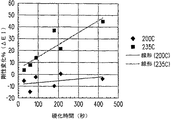
代替的には、含浸済み雲母紙102は、図2Aに示されている通り、加熱プラテンプレス(カーバー(Carver))200を使用することによりプレス加工可能である。加熱プラテンプレス200は、含浸された雲母紙102をその間でプレス加工するのに用いられるプレス対202aおよび202bを有する。この実施例においては、各プレス202aおよび202bは、積層されたカプトンフィルム204aおよび204b、アルミホイル206aおよび206bそしてアルミニウムブロック208aおよび208b(互いに分離された状態で示されている)から作られている。加熱プラテンプレス200は、さまざまな時間、温度および圧力の組合せを調査しながら、含浸済み雲母紙102の試料をプレス加工するために使用されてきた。例えば、含浸済み雲母紙102の試料をプレス加工しながら、2つの温度(200℃および235℃)および最高420秒までの時間が調査された。
Alternatively, the impregnated
支持された薄型テープ方法
樹脂飽和した雲母紙102の2プレート式高温プレス加工を中心とするプロセス開発は、圧力無しの平行な圧密経路方法も追求しながら進められた。この方法においては、樹脂飽和した雲母紙102をシリコーンパッド上に設置しその後前述の熱処理スケジュールによってそれを硬化させることにより、この雲母紙上の圧力を除去するように修正された。この方法は、実際、樹脂飽和した雲母紙102の引裂を有効に防止した。
Supported thin tape method The process development centered on the two-plate high-temperature press working of resin-saturated
垂下式薄型テープ方法
この方法では、含浸および硬化ステップの間雲母紙102を懸吊し支持するように鋳型が開発された。丈夫なアルミニウムホイルの折畳み片の上に雲母紙102の輪郭をトレースすることにより、例示的鋳型を製造した。次にトレースした部域を除去し、鋳型の内側に一片のテープを用いて雲母紙102を取付けた。その後、鋳型を上面に沿って密封し、大型クリップを用いて、リングスタンドからこれを懸吊した。その後、雲母テープ102にゾルシルセスキオキサン106を噴霧し、上述の熱処理スケジュールに従ってこれを硬化させた。必要に応じて、細孔104の含浸済み品質をより良く促進するため、真空オーブン内部において真空下で加熱を行なうことができた。鋳型が雲母紙102の小さい部域を被覆しこれらの部域は処理されなかったためにその縁部を往々にして除去する必要があったにせよ、この方法は最も透明で均等に含浸された雲母紙102を作り出した。この特定の方法は、比較的実施が容易であり、優れた結果をもたらした。
Hanging Thin Tape Method In this method, a mold was developed to suspend and support the
2B.含浸済み雲母紙の結果と特性
目視による特性および顕微鏡による特性
比較的厚いUSサマイカ雲母紙102は、5cmの半径をもつ管のまわりに容易に巻きつけられかつ清澄度が極めて高いものの紙102を通した物体の視界をゆがめる光学散乱を有する含浸済み雲母紙100を作り出した。比較的薄いコジェビの雲母紙102は、5mmの曲率半径のまわりに巻き付けるのに充分な可撓性を有するより透明で可撓性の高い製品を生成した。さらに、コジェビ雲母紙102は、USサマイカ雲母紙102と比較した場合光学散乱に起因するゆがみが著しく少なかった。図2Bは、シルセスキオキサン106での含浸/充填の前後のこれら2種類の雲母紙102の比較を示す。未含浸のUSサマイカ雲母紙102aおよび含浸済みUSサマイカ雲母紙102a’が、左側の写真の中でブックカバーの上面に示されている。又、未含浸のコジェビ雲母紙102bおよび含浸済みコジェビ雲母紙102b’が、右側の写真の中で同じブックカバーの上面に示されている。
2B. Results and properties of impregnated mica paper Visual and microscopic properties The relatively thick US
横断面電子顕微鏡法
2つの含浸済み雲母紙102の研磨された横断面のSEM顕微鏡写真が、図2C(含浸済みUSサマイカ雲母紙102a’)および図2D(含浸済みコジェビ雲母紙102b’)の中に示されている。一般的には、SEM顕微鏡写真は、含浸済み雲母紙102a’および102b’が、(最も明るいコントラストで示された)平行なシート内に大部分が方向づけされた雲母の層状ブック(laminar book)から成ることを表わしている。これらの写真は同様に、ゾル−ゲルシルセスキオキサン106が、大きな内部層状空隙空間ならびに小さい内部層状空間の両方の、複数のタイプの細孔構造を占有していたことをも示している。ここでわかるように、含浸済みUSサマイカ雲母紙102a’は、比較的薄いコジェビ雲母紙102b’に比べて、より粗い構造、より大きい雲母プレートレット(mica platelet)そしてより大きな内部層状空隙を有するように思われる。最も重要なことに、SEM顕微鏡写真は、細孔104を含浸するのに用いられた硬化方法が期せずしてかなり有効であったこと、そして複合構造102a’および102b’が高密度であることを示している。実際、蒸発、オフガス処理または収縮から生じる可能性のある空隙が、SEM顕微鏡写真中には見られなかった。
Cross Section Electron Microscopy SEM micrographs of the polished cross section of two impregnated
表面SEM
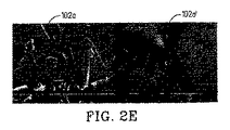
未含浸のUSサマイカ雲母紙102a(左側写真)および含浸済みUSサマイカ雲母紙102a’(右側写真)の表面は、図2Eの250倍SEM顕微鏡写真の中で示されている。そして、未含浸のコンジェビ雲母紙102b(左側写真)および含浸済みコジェビ雲母紙102b’(右側写真)の表面が、図2Fの250倍のSEM顕微鏡写真に示されている。これを見ればわかるように、未含浸USサマイカ雲母紙102aの表面は、大きな雲母ブックの重ね合わさったプレートにより特徴づけられる。実際、USサマイカ雲母紙102a’は、非含浸雲母紙102aおよび硬化済みシルセスキオキサン106にほぼ等しい表面組成を有する一方で、深さが十数マイクロメートルであるように思われるすき間が見える。シルセスキオキサン106は、雲母紙102a内の最も深い空隙の大部分に含浸すると思われたが、表面はなおも不均質であり、有意な表面粗度が明らかであった。これとは対照的に、コジェビ雲母紙102bは、まず粗度が比較的低く、その結果重複した粒子の広がりは比較的小さいものであった。含浸済みコジェビ雲母紙102b’は、わずかにより希薄であり、シルセスキオキサン106は、粒子を互いに粘着させておりかつ雲母紙102bの上部表面上に島状に存在しているのがわかる。この試験において使用された単純なプレス加工および硬化方法は、明らかに、細かく平坦化された表面を提供する場合よりも雲母片の間の大きな空間に含浸する場合により効率の良いものであった。
Surface SEM
The surfaces of unimpregnated US
表面品質−干渉分光法
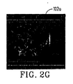
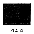
いずれのディスプレイ基板100の表面テクスチャも、その表面上での電子部品の加工後被着を支持できるものである必要がある。例えば、ケイ素被着プロセスでは、粗度が10nm未満の表面上に電子コンポーネントを被着させることが必要である。この実験においては、含浸済み雲母紙102a’および102b’の表面粗度を、WYCO干渉分光法によって測定した。図2Gおよび2Hは、浸潤および2枚のシリコーンプレート間でプレス加工することにより行なわれた圧密の前後のUSサマイカ雲母紙102aおよび102a’の表面マップを示す。ここでわかるように、表面テクスチャは、含浸の前に15マイクロメートルそして含浸後に8マイクロメートルのピークツーバレー高さをもつ雲母片で占められていた。しかしながら、シルセスキオキサン106は、図2EのSEM写真の中で示されたより頻度の高い粗度を削減した。図2Iおよび2Jはそれぞれ、非粘着性アルミニウムホイル単独、および剥離(剤)として非粘着性アルミニウムホイルを用いた2枚の鋼プレート間で圧密された含浸済みUSサマイカ雲母紙102a’の表面粗度を比較している。含浸済みUSサマイカ雲母紙102a’の表面テクスチャは、ホイルのものとほぼ同一であり、これは、硬質プレス表面が雲母粒子および樹脂を立体配座表面(conformational surface)内に移動させることができるということを表わしている。事実、エンボス加工は極めて完全であり、そのため、ブランド名を表わすのに用いられたホイル内にスタンピングされた15マイクロメートルのドットのアレイは、含浸済みUSサマイカ雲母紙102a’の表面に複製された。含浸済みUSサマイカ雲母紙102a’の粗度平均は、約300nm、つまりa−Si被着に必要とされるものの30倍であった。この高忠実度のエンボス加工能力は、圧密の間に平滑エンボス加工方法を使用することにある、表面品質の問題を満たすのに用いることができる別の方法が存在するということを示唆していた。この平滑化プロセスは、付加的なシルセスキオキサン適用ステップとそれに続く連続的ローラー、静止プレスまたはその他のエンボス加工/平滑化方法を含んでいてもよい。さらに、特定の利用分野のための所要表面粗度を達成するために、充填された雲母紙102に対し付加的なシルセスキオキサン106の平坦化層を適用してもよい。
Surface quality-interference spectroscopy The surface texture of any
硬化の機械的評価
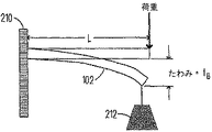
充填済み雲母紙102の試料がひとたび加熱され圧力下で硬化されたならば、パッケージの故障を判定するため、硬化の進行度を監視するための非破壊的方法が望まれた。含浸済み雲母紙102の複合試料がその破壊なく受けた硬化の量を測定する方法が、図2Kの中に示されたもののような片持ち幾何形状210を用いて実証された。ここでわかるように、含浸済み雲母紙102の試料は、支持体/壁210に付着された一方の端部とおもり212に付着されたもう一方の端部を有している。この試験は、含浸済み雲母紙102が荷重の下にある場合に曲がる度合の尺度である弾性たわみfBを決定する。弾性たわみfBは以下のように定義される:
fB=(F*L3)/3*(1/(EI))
式中、F=含浸済み雲母紙102の先端に作用する力、
L=含浸済み雲母紙102の長さ、
E=弾性係数、
I=慣性面積モーメント
(E*I)は、含浸済み雲母紙102の剛性である。
Mechanical Evaluation of Curing Once a sample of filled
f B = (F * L 3 ) / 3 * (1 / (EI))
Where F = force acting on the tip of impregnated
L = length of impregnated
E = elastic modulus,
I = Inertial area moment (E * I) is the stiffness of the impregnated
ここでわかるように、含浸済み雲母紙102のたわみは、含浸済み雲母紙102の剛性に反比例する。この関係は、以下のように表わすことができる:
fBα1/剛性
As can be seen, the deflection of the impregnated
f B α1 / Rigidity
含浸済み雲母紙102が硬化するにつれて、剛性は増大し、かくしてたわみも同様に硬化度に反比例する。この関係は以下のように表わすことができる:
fBα1/「硬化度」
As the impregnated
f B α1 / “Hardness”
次に、印加された質量荷重についてのたわみを測定することにより、含浸済み雲母紙102の4つの試料についてのさまざまな温度における硬化時間とfBの関係を表わす曲線が、図2Lに示されているように構築された。この調査における試料は5cm×5cmであり、質量は6.452gであった。たわみは、試料中のねじれがほとんどまたは全くない状態できわめて均等であった。
Next, curves representing the relationship between cure time and f B at various temperatures for four samples of impregnated
このプロットにおいては、200℃で硬化された含浸済み雲母紙102の2つの試料は、まず最初に、粗たわみ(raw deflection)のわずかな増加を示し、その後より長い時間でたわみのわずかな減少を示すということが認められる。かくして、この低い温度で硬化されたこれら2つの試料についての合計たわみ変化(最初から最後の時間tまで)は、およそゼロであった。しかしながら、235℃で硬化されたその他2つの含浸済み雲母紙102の試料からは、追加された硬化時間でたわみの定常な落ち込みがみられた。ここで、合計たわみ変化は多大であり、200〜400秒の硬化時間の後6〜10mmの大きさであった。
In this plot, two samples of impregnated
この分析をより容易なものとするため、両方の温度における剛性変化%(%ΔEI)対時間のマスター曲線が、以下のようになるように構築された(図2Mに示されたグラフも参照のこと):
%ΔEI=((EIt−EI0)/EI0)*100%=((fB0/fBt)−1)*100%
式中、EIt=時間tにおける剛性変化、
EI0=時間0における初期剛性、
fB0=時間0における初期たわみ、
fBt=時間tにおけるたわみ。
To make this analysis easier, a master curve of% stiffness change (% ΔEI) vs. time at both temperatures was constructed as follows (see also the graph shown in FIG. 2M): thing):
% ΔEI = ((EI t −EI 0 ) / EI 0 ) * 100% = ((fB 0 / fB t ) −1) * 100%
Where EI t = stiffness change at time t,
EI 0 = initial stiffness at
fB 0 = initial deflection at
fB t = deflection at time t.
図2Mに示されているグラフから、より低い200℃の硬化温度については、420秒までの硬化時間について基本的にいかなる変化もない(または非常にわずかな変化しかない)ということが観察できる。一方、235℃というさらに高い硬化時間については、硬化時間が追加されるにつれて試料の含浸済み雲母紙102の剛性が増大したことは明白である。これら2つの曲線の勾配を単純に比較すると、235℃での反応速度(剛性増加)が200℃での反応速度のほぼ7倍であったことがわかる。
From the graph shown in FIG. 2M, it can be observed that for the lower 200 ° C. curing temperature, there is essentially no change (or very little change) for the cure time up to 420 seconds. On the other hand, for the higher cure time of 235 ° C., it is apparent that the stiffness of the sample impregnated
光吸収分光法
ヒューレット・パッカード(Hewlett Packard)8453分光計を用いて300〜1100μmのスペクトル範囲にわたり光吸収について、含浸済み雲母紙102a’および102b’を評価した。ヒューレット・パッカード8453分光計は、電磁スペクトルのUVおよび可視領域内の光を吸収するにつれての分子の電子遷移をプローブ探査することによって機能する。この試験は、透過型ディスプレイコンポーネントでは、可視範囲内での特定の吸収ピークが与えるあらゆる色を最小限におさえ、かつ合計透過を最大限にすることが望ましいことを理由として実施された。しかしながら、基板内部の幾分かの光学散乱度は、OLED光抽出またはその他の目的のために有益であるかもしれない。この試験を実施するために、含浸されたUSサマイカ雲母紙102a’(厚さ80マイクロメートル)および含浸済みコジェビ雲母紙102b’(厚さ15マイクロメートル)を、分光計から約5cmのところで試料ホルダ内に取付けた。この試験で使用されたシルセスキオキサン106は、表3に指示されている通りの組成#1を有していた。スペクトルは図2Nに示されている。
Light Absorption Spectroscopy
ここでわかるように、スペクトルは、UVから青への吸収テールならびに600および800nm近くの小さな吸収を示す。より有意であるのは、全体的減衰がかなり高く、より薄いコジェビ雲母紙102b’についての透過は15%未満、そしてUSサマイカ雲母紙102a’については3%未満であった。そして、厚さについて正規化された場合、減衰は、含浸済み雲母紙の2つの試料102a’および102b’間でほぼ等しいものであった。図2Oは、積分球検出器の備わった日立UV/VIS分光計を用いて含浸済みコジェビ雲母紙102b’上で吸収実験を反復することにより測定された、テクスチャード加工済み試料102a’および102b’の光散乱の影響を示している。この試験においては、プロット内の最高測定値は、積分球検出器で得られ、プロット内の最低測定値は標準透過率検出器設備で得られた。この試験は、含浸済みコジェビ雲母紙102b’の後方に散乱した光を捕捉するように設計されており、従って減衰は、吸収、前方散乱および反射損失に起因すると考えられた。図2Oを見ればわかるように、UVテールからの強い吸収度は青色における透過に影響を与えたが、合計透過はなおも80%近くであった。散乱は、光経路内部の多数の屈折率差から生じると考えられた。残念ながら、試料の複合雲母紙102b’は、シルセスキオキサン106と雲母紙102が同じ屈折率を有するように完全に同調されておらず、その結果、数多くの反射界面が存在し、これが光数の大部分を占めていた。
As can be seen, the spectrum shows an absorption tail from UV to blue and a small absorption near 600 and 800 nm. More significant, the overall attenuation was much higher, the transmission for thinner
熱膨張
図2Pは、ダイナミック・メカニカル(Dynamic Mechanical)分析器によって測定された通りの、含浸済みUSサマイカ雲母紙102a’の膨張挙動を示すグラフである。この試験においては、含浸済みUSサマイカ雲母紙102a’の2×2cm片を20℃〜300℃の温度範囲にわたる寸法変化について測定した。加熱曲線214および冷却曲線216の両方において線形応答が観察され、いかなるヒステリシスも観察されなかった。このことは、含浸済みUSサマイカ雲母紙102a’が測定中に締め固めされないことを表わしていた。これは寸法上の安定性を示している。曲線202および204の勾配から、膨張係数の値は7ppm/℃であるものと計算された。
Thermal Expansion FIG. 2P is a graph showing the expansion behavior of impregnated US
この特定の含浸済みUSサマイカ雲母紙102a’のCTEは、無機シルセスキオキサン106の膨張によって支配され、そのためケイ素層に関する膨張ペナルティ(expansion penalty)はわずか3ppm/℃にすぎなかった(ケイ素は約4ppm/℃の膨張を有する)。これとは対照的に、大部分の重合体基板は、20ppm/℃の範囲内にある高い膨張により特徴づけられている。かくして、従来の重合体基板上に200℃で被着される非晶質ケイ素製品について導出された応力を含浸済みUSサマイカ雲母紙102a’上の300℃の被着プロセスの場合と対比して予想すると、(モジュラスの差を無視し重合体フィルムおよび含浸済み雲母紙102a’についてのそれぞれの比例するΔCTE*ΔT値すなわち重合体基板については[200−40]*180、含浸済み雲母紙102a’については[70−40]*280を計算することにより推定されるように)、重合体基板において3.5倍高い応力が示される。
The CTE of this particular impregnated US
ヘリウム浸透
複合/含浸済み雲母紙102a’および102b’のシートを固定具内に設置し片面をHeで加圧しもう一方の面を排気することにより、ヘリウム浸透を測定した。試料の複合雲母紙102a’および102b’を通過したヘリウムを、次に残留気体分析装置で測定した。この測定に先立ち、システムの完全パージを確実に行う一助となるよう約14時間、試料の複合雲母紙102a’および102b’を排気した。ヘリウムの破過までの時間を測定することにより、比較用浸透挙動を推定した。実際、これは、酸素および水の浸透についての代理測定であり、ヘリウムの拡散率がはるかに高いことからヘリウムの測定によって迅速な評価が可能になるという考えに基づく。
Helium penetration. Helium penetration was measured by placing sheets of composite / impregnated
図2Qは、フレキシブルディスプレイの中で使用できる複数のタイプの有利な材料について測定されたヘリウム流束を示す。従来のトパーズ(Topaz)重合体基板は、その他の重合体システムと比べた場合かなり低い拡散率を提供することがわかっている高温重合体である。合計4つのUSサマイカ雲母紙102a’およびコジェビ雲母紙102b’試料についてのヘリウム流束測定値が、75マイクロメートルの厚さをもつ従来のコーニング(Corning)0211マイクロシート(Micro sheet)ガラス基板を用いて行なわれた測定と共にプロットされた。このタイプの拡散率測定においては、流束が拡散率に正比例し、厚さに対し反比例することを認識すべきである。測定された試料のうち2つのコジェビ雲母紙102b’は、その他の試料の厚さが80マイクロメートル(USサマイカ雲母紙102a’)から最高500マイクロメートル(トパーズ重合体基板)までの範囲内であったのに対し、15マイクロメートルと群を抜いて最薄であった。この測定の2つの局面、すなわち、(時間あたりのヘリウム信号の初期勾配により示される通りの)薄い試料を通してのヘリウムの拡散速度、および定常状態流束が特に重要である。類似の試料についてはこれらの値は互いに相関関係を有していたが、類似ではない試料については、これらの値の各々を定性的に調査することが必要であった。結果は、低い拡散率のマイクロシートガラス基板とかなり浸透性の高い重合体基板の中間位置を、含浸済み雲母紙102a’および102b’が占めていることを示した。1つのケースにおいては、試料のUSサマイカ雲母紙102a’(複合材A)は、非常に低いヘリウム流束を示し、これは、マイクロシートガラス基板にきわめて近いものであった。別のケースにおいては、USサマイカ雲母紙102a’(複合材B)および2つのコジェビ雲母紙102b’は各々、より実質的なものであるヘリウム流束を有していたが、これは、試料の雲母紙102a’および102b’がトパーズ重合体基板より6〜33倍薄いものであるにもかかわらず、トパーズ重合体の流束の1/10以下であった。
FIG. 2Q shows the measured helium flux for several types of advantageous materials that can be used in a flexible display. A conventional Topaz polymer substrate is a high temperature polymer that has been found to provide a much lower diffusivity when compared to other polymer systems. Helium flux measurements for a total of four US
図2Rは、時間の一関数としての複数の含浸済み雲母紙102a’および102b’の相対的He浸透のプロットである。ここでわかるように、(厚さが5分の1であった)プレス加工された雲母紙102a’および102b’の性能は、高い浸透率のUSサマイカ雲母紙102b’(図2Qに示されている複合材B)と類似していた。さらに、300℃で10時間、コジェビ含浸済み雲母紙102b’の1つを経時変化させることにより、流束は約6倍に増大したことがわかる。注釈:この試験で使用された低い屈折率のシルセスキオキサン106をより高い屈折率のシルセスキオキサン106と交換したとすると、流束はさらに2分の1に削減され得たと考えられている。
FIG. 2R is a plot of the relative He penetration of a plurality of impregnated
浸透試験の定性的評価の間に見られた試験対象の複合含浸済み雲母紙102a’および102b’の挙動は、それらが(ポリプロピレン基板よりも1ケタ優れたものであることがわかった)トパーズ重合体基板よりも実質的に低い浸透速度を有することを示した。ただし、究極的な性能は、複合含浸済み雲母紙102a’および102b’の特定の加工によって左右されるように思われた。例えば、浸透は欠陥に敏感であり、試験された雲母紙102a’および102b’で観察された変動の多くが、最適化度の低い加工に起因するものと考えられた。実際、さらなる実験から、含浸済み雲母紙102におけるHe浸透速度が、基板の表面粗度の影響を受ける可能性があり、これにより、試験用器具内のヴィトン(Viton)ガスケットと基板の間のギャップを通した試料含浸済み雲母紙102のまわりの浸透が可能となりうるということがわかった。類似の複合材基板で、USサマイカ雲母紙102a’複合材Aについて得られた性能のいくつかの複製が実証されてきた。さまざまなシルセスキオキサン106の浸透速度はわかっていない(これらがシリコーンおよび重合体に比べてはるかに網状化した構造であることに起因する)ものの、これらが著しく優れた浸透抵抗性を有することが発見されたのは当然であった。
The behavior of the tested composite impregnated
熱重量分析による熱耐久性
この試験においては、部分的に硬化したコジェビ含浸済み雲母紙102b’について熱重量分析を実施した。コジェビ雲母紙102bの複数の試料にシルセスキオキサン106を噴霧により含浸させ、その後試験前に1時間130℃まで予備硬化させた。図2Sは、質量損失事象が260℃、537℃および600℃超を中心としていた、20〜1000℃の温度範囲にわたる熱重量分析結果を示すグラフである。ここでわかるように、部分硬化した雲母紙102b’は、実験全体を通して10%の重量損失を示した。シルセスキオキサン106は試料の合計重量の約30%を構成していることから、損失重量の全てが有機基の焼き払い(burn off)に由来していたという仮定に基づいて、このことは、含浸済み材料106中の約30%の重量損失と相関関係を有していた。グラフ内の示差的トレースは、質量損失事象が次に3つの部域内で発生することを示した:
1.試料が完全に硬化するにつれての水の除去に対応する、200〜300℃での約2%の損失。試料は、当初の水除去のためこれらの温度において熱安定性があるものと予想された。
2.シルセスキオキサン106のマトリクス相からのメチルおよびフェニル基の分解に起因する400〜700℃での約7%の損失。
3.700℃超で約0.5〜1%の損失が、シルセスキオキサン106の連続的酸化、または雲母紙102の脱水に対応していた可能性がある。
Thermal Durability by Thermogravimetric Analysis In this test, a thermogravimetric analysis was performed on partially cured cordieri impregnated
1. About 2% loss at 200-300 ° C. corresponding to water removal as the sample is fully cured. The sample was expected to be thermally stable at these temperatures due to initial water removal.
2. About 7% loss at 400-700 ° C. due to decomposition of methyl and phenyl groups from the matrix phase of
3. About 0.5-1% loss above 700 ° C. may correspond to continuous oxidation of
これらの結果は、複合含浸済み雲母紙102a’および102b’が、網状組織を完全に凝縮させるために250℃近くで加工されるべきであり、潜在的にはこれらを400℃近くの温度で加工することができるという概念を強調した。
These results show that the composite impregnated
熱経時変化による熱SEM耐久性
含浸済みUSサマイカ雲母紙102a’および含浸済みコジェビ雲母紙102b’の試料をまず最初に16分間130℃で、次に10分間180℃で硬化させることによって、これらの試料についての熱耐久性試験を行なった。予備硬化させた含浸済み雲母紙102a’および102b’を次に、異なる温度でさまざまな時間、箱形炉の中で経時変化させた。熱処理の前後に、含浸済み雲母紙102a’および102b’の質量を監視した。さらに、変色またはテクスチャ変化があった場合には、熱処理前にこれを監視した。この試験の結果は、表4および5に提示されている。
含浸済み雲母紙102a’および102b’の試料が完全に硬化しなかったことを考えると、より穏やかな条件(水浸漬85/85、最高300℃で最長10時間の曝露)下での挙動は、きわめて良好であった。
Given that the samples of impregnated
化学的耐久性
両方のタイプの含浸済み雲母紙102a’および102b’をまず最初に45分間150℃そして30分間180℃で硬化させ、その後硬化した含浸済み雲母紙102a’および102b’を一連の化学的曝露に付すことによって、これらの雲母紙についての化学的耐久性試験を実施した。半導体の利用分野において遭遇する可能性のある異なるタイプの加工環境をシミュレートするために、異なる曝露が選択された。
Chemical Durability Both types of impregnated
化学的抵抗性研究
薄いコジェビ含浸済み雲母紙102b’の複数の試料(ここで使用されたシルセスキオキサン106は表3中の組成#1を有していた)を1時間、化学的処理マトリクスに曝露させた。その後1時間試料を60℃のオーブン内で乾燥させ、再度秤量し、外観およびテクスチュアの変化について観察した。さらに、この要領で加工されなかった薄型コジェビ含浸済み雲母紙102b’の試料が2つ存在し、これらを代りにアセトンとイソプロピルアルコールで処理し、再度秤量する前に1時間空気乾燥させた。この試験の結果は表6に示されている。
ここでわかるように、塩基曝露における耐久性は、サンプリングされたコジェビ雲母紙102b’の質量損失および分解を引き起こした。これは、薄型コジェビ雲母紙102bにおける一次雲母相の耐久性の低さに起因する可能性が高かった。これとは対照的に、酸および有機曝露はさほど厳しくなかったが、強リン酸は実際マトリクスの幾分かの軟化を引き起こした。
As can be seen, durability in base exposure caused mass loss and degradation of the sampled
シルセスキオキサンベースの複合材のためには、出発材料としてその他の多孔質形態を使用してもよい。以下の実施例は、可撓性材料100を形成するための前述のプロセスが、無機組成においても多孔率の量および形態においても、多孔質無機形態を広く包含できるということを示している。例えば、シルセスキオキサン106を日本板硝子(Nippon Sheet Glass)製の市販の紙(TGP−010)の中に含浸させることによって、可撓性テープ100が調製された。この実験は、かなり高密度の雲母紙102(前述の通り)から非常に多孔質のガラス繊維紙102(後述の通り)に至るまでの加工能力全般を実証するために行なわれた。この実験は同様に、無機充填材および形状といったようなパラメータにより、充填された多孔質ガラス繊維紙100の特性がいかに影響されるかをも実証した。この実験においては、使用されたTGP010紙102は、90%超の多孔率を有する押出し加工された短繊維であった。紙102の試料を切断し、シルセスキオキサン樹脂106の目標含浸体積をセットするべく秤量した。最終的硬化済み複合材100の目標重量は、原初繊維紙102のマット重量の8.2倍であり、これは、紙102の内部の細孔104を充填するためにどれほどのシルセスキオキサン樹脂106が必要とされるかを表わしていた。
For silsesquioxane-based composites, other porous forms may be used as starting materials. The following examples show that the process described above for forming
次に、表3から処方物2として、所要量のシルセスキオキサン樹脂106を調製した。シルセスキオキサン樹脂106を一晩乾燥させ、秤量した。次に、シルセスキオキサン樹脂106を、処方物の調製されたままの状態の質量の0.914倍まで希釈した。適切な樹脂対ガラス繊維比を提供するべく、紙102に繊維マット1グラムあたり19.4gの希釈したシルセスキオキサン樹脂を配合した。紙がきわめて脆いことから、紙102をセッター上に支持させながら、紙102にゾル106を浸漬させた。各々規定の希釈樹脂106体積の約半分を用いる2回の配合手順が必要とされ、それに続いて12時間室温で乾燥させた。その後、充填された紙102を10分間、200℃で真空オーブン内で予備硬化させ、これにより、粘着性の可撓性テープが残った。
Next, a required amount of
最終的な硬化および表面形成のためには、充填されたテープ102が剥離パッケージ内の2層の間に置かれるホットプレス方法が用いられ、ここで各々の層には、アルミニウムホイルテープの1層とポリイミドフィルムの1層が含まれていた。次に組立てられたパッケージを、カルバー(Carver)油圧プレス内の平行なホットプラテン間に置き、1〜2分間、250℃で均衡化させた。その後、プラテンに対し約100〜1000ポンド(約45〜454kg)または典型的に約100〜200psi(約690〜1380kPa)を印加し、パッケージを30分間250℃で加圧下に保持した。その後圧力を解除し、剥離パッケージを冷却した。(無色でわずかに半透明のテープ100である)ガラス繊維充填樹脂100を、Alホイルおよびカプトンフィルムから剥ぎ取った。このパッケージでは、Alホイル表面は比較的平滑であり、カプトン表面はプレスプロセス中に粗度を防止するのに役立った。代替的なホットプレスパッケージオプションとしては、(1)両方の表面上により多くの残留紙テクスチュアを保持する2つのカプトン層を使用すること、または(2)Alホイルの厚さ変動に起因して全圧力を受けず、従って平滑な表面に完全に適合しないテープ102の領域を導く可能性のある2層のホイルを使用することが含まれる。
For final curing and surface formation, a hot pressing method is used in which the filled
図2Tは、充分に分散した低いガラス繊維画分を示す、結果として得られた充填済みテープ100の横断面のSEMを示している。ガラス繊維は、より暗いシルセスキオキサン106マトリクス内で白色の特長として写っている。複合材テープ100は可撓性であり、7mmのシリンダ全体にわたる多数の曲げに耐えることができる。光吸収試験は、ガラス繊維102とシルセスキオキサン106の屈折率不整合から生じる散乱損失と共に、スペクトル的に中間の色を示した。CTEは、25〜30ppm/℃であるものと測定され、これは、短繊維からの複合効果がほとんどない状態で、シルセスキオキサン106の膨張を反映していた。
FIG. 2T shows a cross-sectional SEM of the resulting filled
代替的な一実施形態においては、別の形態の可撓性充填複合材100を実証するために、カーボンナノチューブ紙102を使用した。この実施形態においては、表3からの処方2としてシルセスキオキサン106を調製した。一晩乾燥した後、シルセスキオキサン106を10分間、カーボン紙と共に140℃まで加熱した。その後、真空下で5分間ゾル106上にカーボンナノチューブ紙ディスク102を浮遊させ、それからシステムを通過させた後、紙102をひっくり返して真空処理を反復した。システムの通気後、紙102を真空オーブン中垂直方向に保持し、その一方でこれを250℃まで1時間加熱してシルセスキオキサン106の硬化を完了させた。温度の上昇中に、一部のシルセスキオキサン樹脂106はカーボン紙102から外に流出した。硬化の後、結果として得たブラックテープ100は、革状で可撓性を有していた(当初0.035gの重さであった紙102がこのプロセスの後0.498gであったという点に留意されたい)。
In an alternative embodiment,
もう1つの実施形態においては、雲母紙102を充填するために含浸用材料106としてケイ酸カリウムを使用した。1つの試験においては、USサマイカ雲母紙102に、2.5というSiO2/K2Oの重量比でケイ酸カリウムの29%固形分水溶液を含浸させた(注釈:PQコーポレーション(PQ Corporation)は、そのカシル(Kasil)(登録商標)製品ライン内でさまざまなケイ酸カリウムを提供している)。溶液を、試料のUSサマイカ雲母紙102a’の表面に塗布し、中に浸漬させた。その後試料のUSサマイカ雲母紙102a’を室温で一晩空気乾燥させ、その後オーブン内において150℃で乾燥させた。形成されたガラス表面に雲母紙102を固着するため、ケイ酸カリウム溶液106をはけ塗りを介してガラスに薄膜として塗布し、その後、その塗布面でガラスに対し雲母紙102を貼り付けた。その後、試料のUSサマイカ雲母紙102a’を乾燥させ硬化させた。これは、隙間または空隙を含む無機材料を含浸させることのできる別の方法および材料システムの一例として役立つ。このタイプの複合材を製造するために必要とされる加工ステップは、1000℃未満の温度にあり、300℃超の温度に耐えることができかつ5cm未満の曲げ半径を有する複合材を提供する。所望の場合、複数の付加的なステップを実施して、化学的硬化を行ない、含浸用材料の機械的耐久性を改変し、化学的耐久性を改変し、或いは又その局所的組成を改変することができる。
In another embodiment, potassium silicate was used as the impregnating
市販の含浸用材料の別の例は、ゲレスト(Gelest)からハードシル(HardSil)(商標)APのブランド名で販売されている。この含浸用材料は、最高360℃の耐用温度をもつ硬化性ポリシルセスキオキサンT−樹脂である。 Another example of a commercially available impregnating material is sold by Gelest under the brand name HardSil ™ AP. This impregnating material is a curable polysilsesquioxane T-resin having a service temperature of up to 360 ° C.
結論
ディスプレイ技術における傾向は、コスト削減および新しい形状因子が将来において増々重要となることを示している。例えば、可撓性基板102のロールを連続するシーケンスで一連の加工ステーション内に通過させ、これにより製造効率を改善することのできる、ディスプレイのリールツーリール式加工が、多大なコスト削減方法とみなされている。引張り応力が加えられた状態で直径30cmのローラーの周囲における曲げに耐えることのできる可撓性基板102の能力は、最終的商品の性能のために望まれるその他の機械的特性に付加的な1つの必要条件を構成している。さらに、適正な靭性を維持しながら最終的ディスプレイを一定サイズに容易に切断する能力も重要である。さらに、ディスプレイの不活動状態が直径2cm未満のロールである、スクロール形態でディスプレイを保管し得る新しい形のフレキシブルディスプレイが想定されている。ここでも又、この極度の可撓性は、画像処理の機能性にとって必要とされるその他の特性に付加的な必要条件である(表1参照)。これらの将来の技術を支持するために、受動および能動マトリクス電子部品を用いる透過型および反射型システム設計のOLED、電気泳動、コレステリック液晶およびケイ素技術を含めた、増大する多数のディスプレイ技術も開発されつつある。その結果、以下の特性の何らかの組合せを可撓性基板100内に有することが重要であると考えられている:(1)30cm未満、5cm未満、1cm未満または0.5cm未満の半径に対する反復的曲げを可能にするための可撓性;(2)300℃超、350℃超または400℃超のa−Si加工またはその他の電子部品を可能にするための熱耐久性;(3)透明性;(4)気体および水に対する低い浸透性;(5)20ppm/℃未満、10ppm/℃未満または7ppm/℃未満の低い膨張;(6)半導体加工液に対する化学的耐久性;(7)85℃/85%RHといったような困難な使用条件下での安定性;(8)0.5マイクロメートル未満、0.3マイクロメートル未満または0.1マイクロメートル未満の表面粗度(Ra)値;(9)1000℃未満、600℃未満または300℃未満の複合製造温度;(10)1.3g/cm3超、1.6g/cm3超、2g/cm3超の密度;(11)200MPa超の引張り強度;(12)1cc/m2/日未満、0.05cc/m2/日未満、0.001cc/m2/日未満(最大)の酸素透過速度;および(12)1g/m2/日未満、0.05g/m2/日未満、0.001g/m2/日未満(最大)の水蒸気遷移速度。ここでわかるように、本明細書で記述された例示的可撓性基板100は、実際、以下のいくつかの所望の有力な特性を有する:
・CTE=7ppm/℃、重合体基板よりもはるかに優れたSiに対する整合。
・重合体基板よりも(2〜3ケタ分)低いもののコーニング・マイクロシートガラス基板よりははるかに高いHe浸透率。
・厚い方のUSサマイカ雲母紙102a’については約5cm、薄い方のコジェビ雲母紙102b’については5mmという曲げ半径能力。
・質量損失または締め固めの無い、350℃に対する熱安定性。
・1週間の期間にわたる85℃/85%RHでの経時変化による著しい影響無し。
・溶剤中での優れた化学的耐久性。
・500℃未満の複合材製造温度。
Conclusion Trends in display technology indicate that cost savings and new form factors will become increasingly important in the future. For example, reel-to-reel processing of displays, which can pass a roll of
CTE = 7 ppm / ° C., much better match for Si than polymer substrate.
-Although it is lower than the polymer substrate (2 to 3 digits), it has a much higher He penetration rate than the Corning microsheet glass substrate.
A bending radius capability of about 5 cm for the thicker US
-Thermal stability to 350 ° C without mass loss or compaction.
No significant effect due to aging at 85 ° C./85% RH over a period of 1 week.
-Excellent chemical durability in solvents.
-Composite material production temperature below 500 ° C.
図3は、本発明の別の実施形態に従ったガラス基板300上の保護コーティングとして使用されている可撓性基板100(含浸済み無機材料100)の横断側面図である。例えば、ガラス基板300は、厚さが50〜100マイクロメートルであり得、保護されていない表面の上に形成された電子デバイス(例えばOLED、半導体、RFID)を有することができる。この利用分野では、ガラス基板300は、全体的バリア性能を提供すると考えられ、可撓性基板100は耐スクラッチ性を提供すると考えられる。特に、可撓性基板100内の無機粒子は、ガラス基板300の表面まで欠陥が伝播するのを阻害することができる。そして可撓性基板100内の無機粒子は、穿刺物体の力を分布させることによってガラス基板300を保護することができる。
FIG. 3 is a cross-sectional side view of a flexible substrate 100 (impregnated inorganic material 100) being used as a protective coating on a
この概念を実証するため、2つの異なる材料すなわちケイ酸カリウムガラス106(例えばSiO2/K2O重量比が2.5であるケイ酸カリウムガラス)およびゾル−ゲルシルセスキオキサン106をそれぞれ使用することによって、イーグル(Eagle)(登録商標)ガラス基板(コーニング社製)に対し2つの未含浸雲母紙102を接着させた。両方のケースにおいて、それぞれの固着剤106は雲母紙102に含浸させ、その後雲母粒子は硬化ステップ後にガラス基板300の表面に固着した。
To demonstrate this concept, two different materials were used, potassium silicate glass 106 (eg, potassium silicate glass with a SiO 2 / K 2 O weight ratio of 2.5) and sol-
別の試験においては、ケイ酸カリウムガラス106を用いて75μmのコーニング0211マイクロシートガラス基板300に、未含浸の市販の雲母紙102をラミネート加工させた。その後、雲母紙がラミネート加工されたマイクロシートガラス基板100/300の上で、リングオンリング強度測定を行なった。さらに、同じ構成のその他の2つの試料セット(300および100/300)を紙やすりで研摩した。研摩は、ラミネート加工された雲母紙が存在する場合、それを有する試料面で行なわれた。3つの試料セット300および100/300全てを次に、研摩された面(存在する場合)に張力を加えた状態で強度試験した。図4は、これらの試料セット300および100/300の各々を破断させるのに必要な平均荷重(力)を比較するプロットである。研摩を受けたおよび受けていないラミネート加工済み試料100/300の試験の結果、類似の破壊荷重が得られた。ただし、裸の研摩済みガラス300の試験は、はるかに低い破壊荷重という結果をもたらした。
In another test, unimpregnated
以下に記すのは、本発明の一部の利点、特徴および用途である:
1.可撓性基板100は、今日用いられている従来の重合体基板に比べて改善されたCTE、加熱能力、O2および水バリア特性、機械的安定性を提供する。これらの特性は全て、最終的利用分野ならびに製造プロセスの両方において利点を提供する。その上、これらの設計における基板材料がその他の重合体基板に比べて低いO2および水浸透値を有するという事実は、潜在的に、低性能/低コストのバリア層108の使用を可能にする。
2.可撓性基板100は、基板の耐久性、寿命、バリア層の微小亀裂に対する抵抗性および製造可能性(フォトリソグラフィによる)を有効に改善する高い寸法安定性を有する。
3.可撓性基板100を薄いガラス基板300にラミネート加工することにより、未保護の薄型ガラス基板に比べ耐久性および耐スクラッチ性が改善される。
4.可撓性基板100は改善された機械的耐久性を有し、存在する可能性のある何らかの表面および縁部欠陥の伝播に起因する破損に対しきわめて高い抵抗性を有する。このことの1つの結果として、潜在的に低コストの切断方法が、機械的耐久性または達成可能な曲げ半径を実質的に減少させずに使用されることになる。
The following are some of the advantages, features and applications of the present invention:
1. The
2. The
3. By laminating the
4). The
本発明の2つの実施形態が添付図面の中に示され、以上の詳細な説明の中で記述されてきたが、本発明は開示された実施形態に制限されず、以下の請求の範囲により規定され定義されている通りの本発明の趣旨から逸脱することなく、数多くの再配置、修正および置換が可能であるということを理解すべきである。 While two embodiments of the invention have been illustrated in the accompanying drawings and described in the foregoing detailed description, the invention is not limited to the disclosed embodiments and is defined by the following claims. It should be understood that numerous rearrangements, modifications, and substitutions are possible without departing from the spirit of the invention as defined and defined.
Claims (14)
雲母紙、
黒鉛紙、
カーボンナノチューブ紙、および
ガラス繊維紙
の中から選択されることを特徴とする請求項1に記載の含浸済み無機材料。 The self-supporting inorganic material is
Mica paper,
Graphite paper,
The impregnated inorganic material according to claim 1, wherein the impregnated inorganic material is selected from carbon nanotube paper and glass fiber paper.
500μm(最大)の厚さ、
20ppm/℃(最大)のCTE、
5cm(最大)の達成可能な曲げ半径、および
0.5μm(最大)の表面粗度
のうちの1つ以上の特性を有することを特徴とする請求項1に記載の含浸済み無機材料。 When the impregnated self-supporting inorganic material / impregnation material is cured / manufactured,
A thickness of 500 μm (maximum),
CTE of 20 ppm / ° C (maximum),
The impregnated inorganic material according to claim 1, characterized in that it has one or more properties of an achievable bending radius of 5 cm (max) and a surface roughness of 0.5 μm (max).
自立形無機材料を提供するステップと、
含浸用材料を提供するステップと、
前記含浸用材料を前記自立形無機材料内部の複数の細孔に含浸させるステップと、
前記含浸済み自立形無機材料を硬化させて前記含浸済み無機材料を形成させるステップと
を含み、含浸および硬化ステップ中の最高温度が1000℃未満であり、硬化された含浸済み無機材料が300℃超の耐用温度を有することを特徴とする製造方法。 A method for producing an impregnated inorganic material,
Providing a self-supporting inorganic material;
Providing a material for impregnation;
Impregnating a plurality of pores inside the self-supporting inorganic material with the impregnating material;
Curing the impregnated freestanding inorganic material to form the impregnated inorganic material, wherein the maximum temperature during the impregnation and curing step is less than 1000 ° C, and the cured impregnated inorganic material is greater than 300 ° C A manufacturing method characterized by having a tolerable temperature.
前記含浸済み自立形無機材料を懸吊するステップと、
前記懸吊された含浸済み自立形無機材料を加熱するステップと
が含まれることを特徴とする請求項7に記載の方法。 The curing step further includes
Suspending the impregnated freestanding inorganic material;
And heating the suspended impregnated free-standing inorganic material.
雲母紙、
黒鉛紙、
カーボンナノチューブ紙、および
ガラス繊維紙
の中から選択されることを特徴とする請求項7に記載の方法。 The self-supporting inorganic material is
Mica paper,
Graphite paper,
8. The method of claim 7, wherein the method is selected from carbon nanotube paper and glass fiber paper.
500μm(最大)の厚さ、
20ppm/℃(最大)のCTE、
5cm(最大)の達成可能な曲げ半径、および/または
0.5μm(最大)の表面粗度
という特性を有することを特徴とする可撓性基板。 A flexible substrate comprising a free-standing inorganic material with a gap impregnated with an impregnating material, wherein the impregnated free-standing inorganic material is cured,
A thickness of 500 μm (maximum),
CTE of 20 ppm / ° C (maximum),
A flexible substrate characterized by having an achievable bend radius of 5 cm (max) and / or a surface roughness of 0.5 μm (max).
1.3g/cm3(最小)超の密度、および/または
200MPa(最小)の引張り強度
という特性を有することを特徴とする請求項11に記載の可撓性基板。 When the impregnated freestanding inorganic material is cured,
The flexible substrate according to claim 11, wherein the flexible substrate has a density of more than 1.3 g / cm 3 (minimum) and / or a tensile strength of 200 MPa (minimum).
1cm/m2/日(最大)未満の酸素透過速度、および/または
1cm/m2/日(最大)未満の水蒸気透過速度
という特性を有することを特徴とする請求項11に記載の可撓性基板。 When the impregnated freestanding inorganic material is cured,
The flexibility according to claim 11, characterized by having an oxygen transmission rate of less than 1 cm / m 2 / day (maximum) and / or a water vapor transmission rate of less than 1 cm / m 2 / day (maximum). substrate.
Applications Claiming Priority (2)
| Application Number | Priority Date | Filing Date | Title |
|---|---|---|---|
| US11/493,741 US20080026180A1 (en) | 2006-07-26 | 2006-07-26 | Impregnated inorganic paper and method for manufacturing the impregnated inorganic paper |
| PCT/US2007/016295 WO2008013719A2 (en) | 2006-07-26 | 2007-07-18 | Impregnated inorganic paper and method for manufacturing the impregnated inorganic paper |
Publications (2)
| Publication Number | Publication Date |
|---|---|
| JP2009544865A true JP2009544865A (en) | 2009-12-17 |
| JP2009544865A5 JP2009544865A5 (en) | 2010-09-02 |
Family
ID=38981982
Family Applications (1)
| Application Number | Title | Priority Date | Filing Date |
|---|---|---|---|
| JP2009521767A Pending JP2009544865A (en) | 2006-07-26 | 2007-07-18 | Impregnated inorganic paper and method for producing the same |
Country Status (6)
| Country | Link |
|---|---|
| US (1) | US20080026180A1 (en) |
| JP (1) | JP2009544865A (en) |
| KR (1) | KR20090035619A (en) |
| CN (1) | CN101495301A (en) |
| TW (1) | TW200819299A (en) |
| WO (1) | WO2008013719A2 (en) |
Families Citing this family (16)
| Publication number | Priority date | Publication date | Assignee | Title |
|---|---|---|---|---|
| WO2010119903A1 (en) * | 2009-04-14 | 2010-10-21 | チッソ株式会社 | Glass fiber-silsesquioxane composite molded article and method for producing same |
| JP2011006610A (en) * | 2009-06-26 | 2011-01-13 | Nagase Chemtex Corp | Transparent composite |
| US20110259416A1 (en) * | 2010-04-27 | 2011-10-27 | Feist Rebekah K | Environmental barrier protection for devices |
| US8580389B2 (en) * | 2010-07-21 | 2013-11-12 | E. I. Dupont De Nemours And Company | Articles comprising phyllosilicate composites containing mica |
| US8449972B2 (en) * | 2010-07-21 | 2013-05-28 | E I Du Pont De Nemours And Company | Phyllosilicate composites containing mica |
| US8652647B2 (en) * | 2010-07-21 | 2014-02-18 | E I Du Pont De Nemours And Company | Articles comprising phyllosilicate composites containing mica |
| US8563125B2 (en) * | 2010-07-21 | 2013-10-22 | E I Du Pont De Nemours And Company | Phyllosilicate composites containing MICA |
| US20120312366A1 (en) * | 2010-12-22 | 2012-12-13 | E. I. Du Pont De Nemours And Company | Fire resistant back-sheet for photovoltaic module |
| KR20120077473A (en) | 2010-12-30 | 2012-07-10 | 삼성모바일디스플레이주식회사 | Flexible substrate and display device including the same |
| CN102363940B (en) * | 2011-09-29 | 2013-09-04 | 嘉兴市秀洲区菲利普自行车有限公司 | Mica paper varnish impregnation controlling method |
| US9522103B2 (en) | 2011-12-20 | 2016-12-20 | Colgate-Palmolive Company | Oral care compositions |
| TWI556953B (en) * | 2013-10-18 | 2016-11-11 | Nat Inst Chung Shan Science & Technology | A metal-based sheet composite graphite sheet |
| GB2520552A (en) * | 2013-11-26 | 2015-05-27 | Nokia Technologies Oy | An apparatus for user input and/or user output |
| CN106120466B (en) * | 2016-07-01 | 2018-10-30 | 昆明纳太科技有限公司 | High-temp. resistant air filter paper and preparation method thereof |
| CN110421904A (en) * | 2019-07-31 | 2019-11-08 | 东莞市汇驰纸业有限公司 | A kind of processing method regenerating corrugated board |
| EP3819114A1 (en) * | 2019-11-06 | 2021-05-12 | COGEBI société anonyme | Mica based sandwich structures |
Citations (6)
| Publication number | Priority date | Publication date | Assignee | Title |
|---|---|---|---|---|
| US2953466A (en) * | 1956-08-09 | 1960-09-20 | North American Aviation Inc | Silicon-mica composition |
| JPS526741A (en) * | 1975-06-30 | 1977-01-19 | Philadelphia Quartz Co | Starchhsilicic acid adhesive and production method |
| JPH02199190A (en) * | 1988-11-28 | 1990-08-07 | Royale Asturienne De Mines:Co | Application of impregnated mica paper composition for covering structural element,and structural element thus obtained |
| JPH0586596A (en) * | 1991-09-25 | 1993-04-06 | Nippon Sheet Glass Co Ltd | Flake-like inorganic substance-mixed paper |
| JPH0921100A (en) * | 1993-11-19 | 1997-01-21 | Nippon Muki Co Ltd | Inorganic paper molding and its production |
| WO2006007385A1 (en) * | 2004-06-15 | 2006-01-19 | Siemens Power Generation, Inc. | Structured resin systems with high thermal conductivity fillers |
Family Cites Families (18)
| Publication number | Priority date | Publication date | Assignee | Title |
|---|---|---|---|---|
| US2595727A (en) * | 1945-03-09 | 1952-05-06 | Westinghouse Electric Corp | Organosiloxanes containing methallyl silicon oxide groups |
| US2647069A (en) * | 1947-01-23 | 1953-07-28 | Philadelphia Quartz Co | Manufacture of silicate-coated papers |
| US2948329A (en) * | 1956-09-24 | 1960-08-09 | Gen Electric | Mica paper |
| US2934464A (en) * | 1958-12-18 | 1960-04-26 | Dow Corning | Organosiloxane resin compositions and glass laminates impregnated therewith |
| US3332817A (en) * | 1966-03-24 | 1967-07-25 | Sprague Electric Co | Method of making a mica paper capacitor |
| US4559264A (en) * | 1983-01-27 | 1985-12-17 | Corning Glass Works | Synthetic mica products |
| US4460639A (en) * | 1983-04-06 | 1984-07-17 | Dow Corning Corporation | Fiber reinforced glass matrix composites |
| US4803113A (en) * | 1985-09-30 | 1989-02-07 | Essex Group, Inc. | Corrugated mica product |
| US4670351A (en) * | 1986-02-12 | 1987-06-02 | General Electric Company | Flexible printed circuits, prepared by augmentation replacement process |
| US4683162A (en) * | 1986-04-09 | 1987-07-28 | Essex Group, Inc. | Mica product |
| US4857395A (en) * | 1987-10-08 | 1989-08-15 | The Standard Oil Company | Graphite composites and process for the manufacture thereof |
| US5991493A (en) * | 1996-12-13 | 1999-11-23 | Corning Incorporated | Optically transmissive bonding material |
| US6144795A (en) * | 1996-12-13 | 2000-11-07 | Corning Incorporated | Hybrid organic-inorganic planar optical waveguide device |
| EP0966001A1 (en) * | 1998-06-17 | 1999-12-22 | COMPAGNIE ROYALE ASTURIENNE DES MINES, Société Anonyme | Manufacture of a mica tape and obtained product |
| WO2000046622A1 (en) * | 1999-02-05 | 2000-08-10 | Corning Incorporated | Optical fiber component with shaped optical element and method of making same |
| JP4586310B2 (en) * | 2001-07-04 | 2010-11-24 | 株式会社Ihi | Manufacturing method of ceramic composite member |
| US7520790B2 (en) * | 2003-09-19 | 2009-04-21 | Semiconductor Energy Laboratory Co., Ltd. | Display device and manufacturing method of display device |
| US20050214556A1 (en) * | 2004-02-20 | 2005-09-29 | Fuji Photo Film Co., Ltd | Organic-inorganic composite composition, plastic substrate, gas barrier laminate film, and image display device |
-
2006
- 2006-07-26 US US11/493,741 patent/US20080026180A1/en not_active Abandoned
-
2007
- 2007-07-18 WO PCT/US2007/016295 patent/WO2008013719A2/en active Application Filing
- 2007-07-18 JP JP2009521767A patent/JP2009544865A/en active Pending
- 2007-07-18 CN CNA2007800287353A patent/CN101495301A/en active Pending
- 2007-07-18 KR KR1020097004087A patent/KR20090035619A/en not_active Application Discontinuation
- 2007-07-23 TW TW96126900A patent/TW200819299A/en unknown
Patent Citations (6)
| Publication number | Priority date | Publication date | Assignee | Title |
|---|---|---|---|---|
| US2953466A (en) * | 1956-08-09 | 1960-09-20 | North American Aviation Inc | Silicon-mica composition |
| JPS526741A (en) * | 1975-06-30 | 1977-01-19 | Philadelphia Quartz Co | Starchhsilicic acid adhesive and production method |
| JPH02199190A (en) * | 1988-11-28 | 1990-08-07 | Royale Asturienne De Mines:Co | Application of impregnated mica paper composition for covering structural element,and structural element thus obtained |
| JPH0586596A (en) * | 1991-09-25 | 1993-04-06 | Nippon Sheet Glass Co Ltd | Flake-like inorganic substance-mixed paper |
| JPH0921100A (en) * | 1993-11-19 | 1997-01-21 | Nippon Muki Co Ltd | Inorganic paper molding and its production |
| WO2006007385A1 (en) * | 2004-06-15 | 2006-01-19 | Siemens Power Generation, Inc. | Structured resin systems with high thermal conductivity fillers |
Also Published As
| Publication number | Publication date |
|---|---|
| CN101495301A (en) | 2009-07-29 |
| KR20090035619A (en) | 2009-04-09 |
| TW200819299A (en) | 2008-05-01 |
| WO2008013719A2 (en) | 2008-01-31 |
| WO2008013719A3 (en) | 2008-03-27 |
| US20080026180A1 (en) | 2008-01-31 |
Similar Documents
| Publication | Publication Date | Title |
|---|---|---|
| JP2009544865A (en) | Impregnated inorganic paper and method for producing the same | |
| Hrubesh et al. | Thin aerogel films for optical, thermal, acoustic and electronic applications | |
| Kim et al. | Thermally stable transparent sol− gel based siloxane hybrid material with high refractive index for light emitting diode (LED) encapsulation | |
| US20150217532A1 (en) | Method of manufacturing a laminate provided with a concave-convex structure and transfer film | |
| CN101877331A (en) | Flexible substrate for display panel and manufacturing method thereof | |
| Yin et al. | Hierarchical surface wrinkles directed by wrinkled templates | |
| KR101675093B1 (en) | Manufacturing method of flexible transparent substrate and flexible transparent substrate thereof | |
| Zhang et al. | Large-area, crack-free polysilazane-based photonic crystals | |
| JP5582355B2 (en) | Composite material, composite film produced thereby, and method for producing composite film | |
| JP6321331B2 (en) | COMPOSITE SHEET, MANUFACTURING METHOD THEREOF AND DISPLAY SUBSTRATE INCLUDING THE SAME | |
| JPWO2020017480A5 (en) | ||
| EP3892688A1 (en) | Curable organopolysiloxane composition for forming film and production method for organopolysiloxane cured product film | |
| JP2006017169A (en) | Vacuum heat insulating material, core material for vacuum heat insulating material and its producing method | |
| TW201629166A (en) | Curable silicone formulations and related cured products, methods, articles, and devices | |
| KR101489959B1 (en) | Gas barrier film, method for preparing thereof and display display member comprising the same | |
| Tang et al. | Preparation of fumed silica compacts for thermal insulation using wet processing method | |
| Zong et al. | Unusual inorganic phase formation in ultraviolet‐curable organic–inorganic hybrid films | |
| KR20210019532A (en) | Imprinting composition and method for forming patterned layer using same | |
| CN110612324A (en) | Transparent composite film and flexible display device comprising same | |
| WO2013129307A1 (en) | Method for manufacturing sealing resin sheet | |
| TW201906932A (en) | Solid organic germanium material, laminated body using the same, and light-emitting element | |
| Ferchichi et al. | Relation between structure and mechanical properties (elastoplastic and fracture behavior) of hybrid organic–inorganic coating | |
| JP2005298796A (en) | Organic metal polymer material and its preparation process | |
| Boyer et al. | Microfabrication with smooth thin carbon nanotube composite sheets | |
| CN110757919A (en) | Novel buffer cushion |
Legal Events
| Date | Code | Title | Description |
|---|---|---|---|
| A521 | Written amendment |
Free format text: JAPANESE INTERMEDIATE CODE: A523 Effective date: 20100714 |
|
| A621 | Written request for application examination |
Free format text: JAPANESE INTERMEDIATE CODE: A621 Effective date: 20100714 |
|
| A521 | Written amendment |
Free format text: JAPANESE INTERMEDIATE CODE: A523 Effective date: 20110207 |
|
| A977 | Report on retrieval |
Free format text: JAPANESE INTERMEDIATE CODE: A971007 Effective date: 20120117 |
|
| A131 | Notification of reasons for refusal |
Free format text: JAPANESE INTERMEDIATE CODE: A131 Effective date: 20120124 |
|
| A02 | Decision of refusal |
Free format text: JAPANESE INTERMEDIATE CODE: A02 Effective date: 20120703 |