JP2009544524A - Container assembly for storing vehicle windshield or headlight cleaning fluid - Google Patents
Container assembly for storing vehicle windshield or headlight cleaning fluid Download PDFInfo
- Publication number
- JP2009544524A JP2009544524A JP2009521365A JP2009521365A JP2009544524A JP 2009544524 A JP2009544524 A JP 2009544524A JP 2009521365 A JP2009521365 A JP 2009521365A JP 2009521365 A JP2009521365 A JP 2009521365A JP 2009544524 A JP2009544524 A JP 2009544524A
- Authority
- JP
- Japan
- Prior art keywords
- hollow structure
- container assembly
- assembly according
- pump
- container
- Prior art date
- Legal status (The legal status is an assumption and is not a legal conclusion. Google has not performed a legal analysis and makes no representation as to the accuracy of the status listed.)
- Abandoned
Links
Images


Classifications
-
- B—PERFORMING OPERATIONS; TRANSPORTING
- B60—VEHICLES IN GENERAL
- B60S—SERVICING, CLEANING, REPAIRING, SUPPORTING, LIFTING, OR MANOEUVRING OF VEHICLES, NOT OTHERWISE PROVIDED FOR
- B60S1/00—Cleaning of vehicles
- B60S1/02—Cleaning windscreens, windows or optical devices
- B60S1/46—Cleaning windscreens, windows or optical devices using liquid; Windscreen washers
- B60S1/48—Liquid supply therefor
- B60S1/50—Arrangement of reservoir
-
- Y—GENERAL TAGGING OF NEW TECHNOLOGICAL DEVELOPMENTS; GENERAL TAGGING OF CROSS-SECTIONAL TECHNOLOGIES SPANNING OVER SEVERAL SECTIONS OF THE IPC; TECHNICAL SUBJECTS COVERED BY FORMER USPC CROSS-REFERENCE ART COLLECTIONS [XRACs] AND DIGESTS
- Y10—TECHNICAL SUBJECTS COVERED BY FORMER USPC
- Y10T—TECHNICAL SUBJECTS COVERED BY FORMER US CLASSIFICATION
- Y10T137/00—Fluid handling
- Y10T137/8593—Systems
- Y10T137/85978—With pump
- Y10T137/86035—Combined with fluid receiver
Landscapes
- Engineering & Computer Science (AREA)
- Water Supply & Treatment (AREA)
- Mechanical Engineering (AREA)
- Body Structure For Vehicles (AREA)
- Cooling, Air Intake And Gas Exhaust, And Fuel Tank Arrangements In Propulsion Units (AREA)
Abstract
【課題】車両への搭載が容易なフロントガラス又はヘッドライトの洗浄液を入れる容器組立体を提供する。
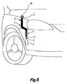
【解決手段】 本発明の容器組立体は、細長い中空構造体1と、注入開口2と、ポンプ5とを有する。中空構造体1は、複数のアコーディオン状の折り畳み部材の壁により形成され、前記アコーディオン状の折り畳み部材により、前記中空構造体は、安定した収縮状態とフレキシブルな拡張状態とを有し、これにより車両のエンジン・ルームの有効スペース内に搭載可能となり、前記拡張状態の中空構造体は、フロントガラス又はヘッドライトの洗浄液を収納でき、前記注入開口2は、前記中空構造体1の入口端部分15に配置され、ポンプ5は、中空構造体に取り付けられ、洗浄液を放出ポイントまで搬送する。
【選択図】 図5
A container assembly for storing a cleaning solution for a windshield or a headlight that can be easily mounted on a vehicle is provided.
A container assembly according to the present invention includes an elongated hollow structure, an injection opening, and a pump. The hollow structure 1 is formed by walls of a plurality of accordion-like folding members, and the accordion-like folding member causes the hollow structure to have a stable contracted state and a flexible expanded state, whereby a vehicle The expanded hollow structure can accommodate windshield or headlight cleaning liquid, and the injection opening 2 is formed in the inlet end portion 15 of the hollow structure 1. Arranged, the pump 5 is attached to the hollow structure and carries the cleaning liquid to the discharge point.
[Selection] Figure 5
Description
本発明は、車両のフロントガラス又はヘッドライトの洗浄液を入れる容器の組立体に関する。この容器組立体は、モータで駆動されるポンプに連結された拡張可能タンクと、この容器組立体を車両のエンジン・ルームに取り付ける手段とを有する。 The present invention relates to a container assembly for containing a cleaning liquid for a windshield or a headlight of a vehicle. The container assembly includes an expandable tank coupled to a motor driven pump and means for attaching the container assembly to a vehicle engine room.
本発明は、ヘッドライト洗浄液の容器を例に説明するが、本発明はフロントガラス洗浄液の容器組立体とヘッドライト洗浄液の容器組立体の両方に適応可能である。 Although the present invention will be described using a headlight cleaning liquid container as an example, the present invention is applicable to both a windshield cleaning liquid container assembly and a headlight cleaning liquid container assembly.
特許文献1は、フロントガラス洗浄液のタンクを開示する。このタンクは、その両端で前壁と後壁により閉鎖されたアコーディオン状の折り畳み部材を具備する管状部分から形成される。この管状部分は、前後方向に収縮し衝撃を受けた時に破損することはない。特許文献1の構成は、タンクをエンジン・ルーム内に組み込むための配置装置あるいは非常に特殊な装置が必要である。しかし特許文献1は、アコーディオン状の折り畳み部材を具備する管状部分が、保管時あるいは輸送時にスペースを節約するのに適したコンパクトで安定した収縮状態を採ることを開示していない。
特許文献2は、第1の剛性のメインタンク部分と第2の拡張可能な補助タンク部分とからなるフロントガラス洗浄液のタンクを開示する。この第1タンク部分は、流体を駆動するポンプを搭載する。一方、第2タンク部分は、アコーディオン状の折り畳み部材を具備する。これら2個のタンク部分は、適宜の拡張部分を具備し、ラック上に搭載される。この拡張部分が、第2タンク部分の拡張/収縮する部分を構成し、タンク全体の容積を可変にしている。特許文献2の構成は、エンジン・ルーム内の限られた場所に特殊な配置装置を必要とし、アコーディオン状の折り畳み部材を有する補助タンク部分が、コンパクトで安定した収縮状態を採ることを開示していない。さらに曲がりくねった狭いスペースに収納できるフレキシブルな構造体を開示していない。
特許文献3は、車両内の洗浄液用剛性タンクを開示する。この剛性タンクは、フレキシブルな複数のアコーディオン状の折り畳み部材により形成された壁を具備する充填用チューブを搭載する。このフレキシブルな充填用チューブは、タンクとして機能せず、充填操作の間、充填用開口から剛性タンク内に流体を導く機能を果たすだけである。 Patent Document 3 discloses a rigid tank for cleaning liquid in a vehicle. This rigid tank carries a filling tube having a wall formed by a plurality of flexible accordion-like folding members. This flexible filling tube does not function as a tank, but only serves to direct fluid from the filling opening into the rigid tank during the filling operation.
アコーディオン状の折り畳み部材を具備するチューブの構造は公知であり、特に特許文献4、5に開示されている。上記の特許は、幾つかのアプリケーションを開示する。例えば、フレキシブルな接続チューブと、トラップ・ドレイン、コンテナ用の格納式ネックと、小型構造の折り畳み式コンテナの本体部分を開示する。しかしこれらの特許文献は、ポンプに関連した車両のフロントガラス又はヘッドライトの洗浄液を入れるフレキシブルで細長いタンクの構造を開示しない。
The structure of a tube having an accordion-like folding member is known, and is disclosed in
特許文献6は、フロントガラス洗浄液用の導管を開示する。この導管は、複数の平滑な部分で分離された複数の波形部分を具備するマニホールドを有し、その両端に露出しない結合手段を具備する折り畳んだ部分を含む。他の従来技術と同様に、特許文献6は、上記の導管を通る循環機能あるいは流体のガイドを開示するが、流体保管用の使用可能なポンプとの関連については開示していない。 U.S. Patent No. 6,057,051 discloses a conduit for windshield cleaning liquid. The conduit has a manifold with a plurality of corrugations separated by a plurality of smooth portions and includes a folded portion with coupling means not exposed at both ends thereof. As with other prior art, US Pat. No. 6,057,086 discloses a circulating function or fluid guide through the conduit described above, but does not disclose its association with an available pump for fluid storage.
本発明は、フロントガラス又はヘッドライト洗浄液のタンクあるいは容器の新たな構造体を提供する。この本発明の構造体は、車両のエンジン・ルーム内の特に製造、物流、組立が容易である。 The present invention provides a new structure for a windshield or headlight cleaning liquid tank or container. This structure of the present invention is particularly easy to manufacture, distribute and assemble in the engine room of a vehicle.
本発明は、車両のフロントガラス又はヘッドライトの洗浄液を入れる容器組立体に関する。本発明の容器組立体は、非対称の複数のアコーディオン状の折り畳み部材を具備する細長い中空構造体を有する。この折り畳み部材により中空構造体は、安定した収縮状態とフレキシブルな拡張状態を採ることができる。この中空構造体が拡張状態にある時は、車両のエンジン・ルーム内に搭載されている時である。拡張状態にある中空構造体は、所定量の洗浄液と所定の柔軟性と伸長性を提供する。この為、異常に小さく曲がりくねったスペース内に配置できる。本発明の容器組立体は、中空構造体の入口端部分に配置された充填用開口と中空構造体の出口端部分に配置された出口部分とを有する。 The present invention relates to a container assembly for containing a cleaning liquid for a windshield or a headlight of a vehicle. The container assembly of the present invention has an elongated hollow structure with a plurality of asymmetric accordion-like folding members. With this folding member, the hollow structure can take a stable contracted state and a flexible expanded state. The hollow structure is in an expanded state when it is mounted in the engine room of the vehicle. The hollow structure in the expanded state provides a predetermined amount of cleaning liquid and predetermined flexibility and extensibility. For this reason, it can be placed in an unusually small and winding space. The container assembly of the present invention has a filling opening disposed at the inlet end portion of the hollow structure and an outlet portion disposed at the outlet end portion of the hollow structure.
本発明の一実施例によれば、本発明の容器組立体は、前記出口端部分に結合され、ポンプを支持するポンプ支持部材をさらに有する。ポンプの吸引口は、前記出口開口と連通する。固定手段が、前記入口端部分と前記ポンプ支持部材をエンジン・ルームに固定するために搭載される。その際に注入開口は出口開口よりも高い位置にある。複数の固定装置が、注入開口部分と出口開口との間にある中空構造体の複数の部分をエンジン・ルームに固定する。その結果、車両の移動中あるいはスピードの変化(加速とブレーキ)の間、容器の安定性を確保できる。 According to an embodiment of the present invention, the container assembly of the present invention further includes a pump support member coupled to the outlet end portion and supporting the pump. The suction port of the pump communicates with the outlet opening. A securing means is mounted for securing the inlet end portion and the pump support member to the engine room. At that time, the injection opening is located higher than the outlet opening. A plurality of securing devices secure a plurality of portions of the hollow structure between the injection opening and the outlet opening to the engine compartment. As a result, the stability of the container can be ensured during movement of the vehicle or during speed changes (acceleration and braking).
本発明の容器組立体は、幾つかの利点がある。第1の利点は、容器組立体を車両に搭載していない時は、容器組立体はコンパクトで安定した収縮状態を採り、剛性チューブやタンクの組立体と比較すると、タンクの保管時や輸送時に占めるスペースが少なくてすむ。さらに本発明の容器組立体の拡張可能タンク部分が拡張状態を採る時は、この拡張可能タンク部分は、極めてフレキシブルで車両のエンジン・ルーム内の利用可能なスペースに容易に収納できる。これにより狭いスペースは、互いに必ずしも直線状である必要はなく、また通常時利用されない空間を利用できる。同じ理由により、フロントガラス又はヘッドライトの洗浄液用容器のスペースの確保が可能であり、車両の設計段階では、洗浄液の容器のことを考慮する必要はない。本発明の容器組立体の一種類のモデルでも、様々なモデルの車両に適用可能である。さらに本発明の容器組立体は、固定装置を除いて、一体部品で形成することができ、これはプラスチック材料の押し出し成形/吹き出し成形法により製造できるために利点がある。本発明は、製造、保管、輸送、搭載、保守、置換の簡素化の点でも利点がある。 The container assembly of the present invention has several advantages. The first advantage is that when the container assembly is not mounted on the vehicle, the container assembly is compact and has a stable contracted state. Compared to the rigid tube and tank assembly, the container assembly is more easily stored and transported. It takes up less space. Further, when the expandable tank portion of the container assembly of the present invention is in an expanded state, the expandable tank portion is extremely flexible and can be easily stored in an available space in the vehicle engine room. Thereby, the narrow space does not necessarily need to be linear with each other, and a space that is not normally used can be used. For the same reason, it is possible to secure the space for the cleaning liquid container of the windshield or the headlight, and it is not necessary to consider the cleaning liquid container at the vehicle design stage. One kind of model of the container assembly of the present invention can be applied to various models of vehicles. Furthermore, the container assembly of the present invention can be formed as a single piece except for the fixing device, which is advantageous because it can be manufactured by an extrusion / blow molding process of plastic material. The present invention is also advantageous in terms of simplification of manufacturing, storage, transportation, mounting, maintenance, and replacement.
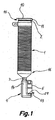
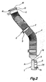
図1、2において、本発明の一実施例のフロントガラス又はヘッドライトの洗浄液を入れる容器の組立体は、フレキシブルで拡張可能な中空構造体1と、前記中空構造体1の端部に結合されるポンプ支持部材4と、複数個の固定装置6とを有する。本発明の容器組立体は、車両のフロントガラス又はヘッドライトの洗浄システムに組み込まれる。中空構造体1は、複数の非対称のアコーディオン状の折り畳み部材を有する。この折り畳み部分により、中空構造体1は、図1の収縮状態又は図2の拡張状態に配置できる。中空構造体1が収縮状態にある時には、中空構造体1は、保管と輸送用に適したコンパクトで縮まった形状を有する。中空構造体1が拡張状態にある時には、中空構造体1は、フレキシブルになり、車両のエンジン・ルーム内に搭載されるのに適するようになる(図5)。拡張状態の中空構造体1は、「相当量」のフロントガラス又はヘッドライトの洗浄液を収納できる容量を有する。「相当量」とは、フロントガラス又はヘッドライトの洗浄液のタンクの製造業者が通常予測する量を言う。例えば、中空構造体1がヘッドライト洗浄システム用の場合には、中空構造体1は、拡張状態で2.5から5リットルの間の容量を有し、中空構造体1がフロントガラス洗浄システム用の場合には、中空構造体1は、拡張状態で2.5から3リットルの間の容量を有する。
1 and 2, an assembly of a container for storing a windshield or headlight cleaning liquid according to an embodiment of the present invention is coupled to a flexible and expandable
図1−4に示す実施例において、中空構造体1は、洗浄液の注ぎ口である注入開口2と出口開口3とを有する。注入開口2は、中空構造体1の入口端部分15に配置される。出口開口3は、中空構造体1の出口端部分16に配置される。ポンプ支持部材4は出口端部分16に結合される。このポンプ支持部材4はモータで駆動されるポンプ5を支持する。ポンプ5の吸引口12(図10に示す)は出口開口3と連通する。ポンプ支持部材4は容器14を有する。この容器14内に中空構造体1の出口開口3が入り込む。ポンプ5の吸引口12は、容器14の出口に接続される。ポンプ5は、放出口13を有する。この放出口13は、フロントガラス又はヘッドライトの洗浄システムの導管装置に接続される。ポンプ支持部材4は、弾性構造体29を有する。この弾性構造体29は、弾性変形するスナップ・フィットにより、ポンプ5を収納し保持する。容器14の出口は、ポンプ5の吸引口12の結合部を、封止用ガスケットによる圧力結合により収納する。
In the embodiment shown in FIGS. 1 to 4, the
入口端部分15とポンプ支持部材4は、固定手段を有する。この固定手段は、容器組立体を車両のエンジン・ルームに固定する。その際、注入開口2が出口開口3より上にくるようにする。容器組立体1は複数個の固定装置6を有する。この固定装置6は、注入開口2と出口開口3の間にある中空構造体1の複数の部分を、エンジン・ルームに固定する。固定装置6の数は、中空構造体1の長さと構造によって変化する。いずれの場合も、その数は、中空構造体1を保持し係合するのに適した数である。更に容器が洗浄液で満杯状態で車両の走行中に加速度に曝された時に、容器の壁にかかるストレス(液体圧力による)を最小にするような数である。
The
本発明の一実施例によれば、中空構造体1と、入口端部分15と、出口端部分16と、容器14を含むポンプ支持部材4とは、一体に形成される。これは、プラスチック材料の押し出し成形法/吹き出し成形法により製造するためである。本発明の他の実施例(図示せず)によれば、中空構造体1と入口端部分15と出口端部分16とを一体に形成し、容器14を含むポンプ支持部材4は、別の部品で形成してもよい。中空構造体1と、入口端部分15と、出口端部分16と、容器14を含むポンプ支持部材4とを別の部品として形成してもよい。入口端部分15にはふた10がはまる。ふた10は、中空構造体1の入口端部分15に連結ビーズ11で連結される。ふた10と連結ビーズ11とは、容器組立体を形成する一体部品で形成できる。そのような場合、中空構造体1と、入口端部分15と、出口端部分16と一体部品にするか、あるいは入口端部分15のみと一体部品にしてもよい。
According to one embodiment of the present invention, the
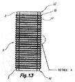
図6、7に示すように、各固定装置6は、フランジとベース8とを有する。このフランジは、中空構造体1の一部を少なくとも部分的に包囲する。このベース8は、エンジン・ルームに取り付けられる。固定装置6のフランジは、一対の弾性アーム7から構成される。この弾性アーム7は、弾性変形のスナップ・フィットにより、中空構造体1の一部を包囲し固定する。この中空構造体1にアコーディオン状の折り畳み部材が形成される。このアコーディオン状の折り畳み部材は、谷部17と山部18とを有する。弾性アーム7は、内側リブ9を具備する。この内側リブ9が、1個或いは複数個の谷部17内にはまりこみ、弾性アーム7が、折り畳み部材の山部8上をスライドするのを阻止する。別の構成として、図8に示すように、弾性アーム7は、折り畳み部材の山部18上に支持される平滑な内側表面19を有してもよい。選択的事項として、図9の実施例において、中空構造体1は、アコーディオン状の折り畳み部材1aの間に配置される平滑部分1bを有してもよい。平滑部分1bは、折り畳み部材1aの最大横方向寸法(即ち、山部18の外径)よりも小さな横方向寸法(例えば、谷部17の外径)を有する。弾性アーム7が、中空構造体1の平滑部分1bに、弾性変形のスナップ・フィットにより結合される。
As shown in FIGS. 6 and 7, each fixing device 6 has a flange and a base 8. This flange at least partially surrounds a part of the
別の構成として、本発明の他の実施例(図示せず)によれば、容器は1個の固定装置6を有する。この固定装置6は、エンジン・ルームに固定されるベースと、複数個の離間して配置されたフランジとを有する。このフランジは、中空構造体の複数の部分を少なくとも部分的に包囲する。固定装置6は、他の変形例として、1個又は複数個のベースに結合されたくさび状構造を有してもよい。このくさび状構造が、中空構造体1の複数の部分を少なくとも部分的に包囲する。
Alternatively, according to another embodiment (not shown) of the invention, the container has a single fixing device 6. This fixing device 6 has a base fixed to the engine room and a plurality of spaced flanges. The flange at least partially surrounds the plurality of portions of the hollow structure. As another modification, the fixing device 6 may have a wedge-shaped structure coupled to one or a plurality of bases. This wedge-shaped structure at least partially surrounds the plurality of portions of the
図1、2に示す実施例において、中空本体は断面が円形である。しかし本発明の中空構造体1は、楕円あるいは多角形の断面でもよい。
1 and 2, the hollow body has a circular cross section. However, the
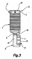
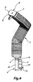
図3、4の容器組立体と図1、2の容器組立体との相違点は、図3,4の中空構造体1の断面が円形ではなく多角形である点である。従って、入口端部分15と、ふた10と、出口端部分16は、互いに適合する多角形をしている。固定装置のフランジは、それらに合う多角形をしている。ポンプ支持部材4と容器14も同様である。
The difference between the container assembly of FIGS. 3 and 4 and the container assembly of FIGS. 1 and 2 is that the cross section of the
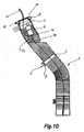
図10、11、12は、中空構造体1に接続されるポンプ5の変形例を示す。
10, 11, and 12 show a modification of the pump 5 connected to the
図10において、ポンプ5は、中空構造体1の中側で注入開口2に隣接して搭載される。吸入チューブ20は、ポンプ5の吸引口12に接続され、容器の底部まで伸びる。
In FIG. 10, the pump 5 is mounted adjacent to the injection opening 2 on the inside of the
図11において、ポンプ5は、中空構造体1の中側で容器の底部に隣接して搭載される。前記ポンプ5は、前記洗浄液内に入っている時に、動作するポンプである。ポンプ5の吸引口12が容器の底にあり、マニホールド21の一端は、容器を通り注入開口2から出て、他端は、ポンプの放出口13に連結される。
In FIG. 11, the pump 5 is mounted adjacent to the bottom of the container on the inside of the
図12において、ポンプ5は、中空構造体1に取り付けられ、その吸引口12は、構造体の出口開口3に直接連結される。
In FIG. 12, the pump 5 is attached to the
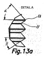
図13aの詳細は、中空構造体1のアコーディオン状部材の壁の形状と傾斜を示す。この実施例において、角度αは約47度で、角度βは約33度である。
The detail of FIG. 13 a shows the shape and inclination of the wall of the accordion-like member of the
以上の説明は、本発明の一実施例に関するもので、この技術分野の当業者であれば、本発明の種々の変形例を考え得るが、それらはいずれも本発明の技術的範囲に包含される。特許請求の範囲の構成要素の後に記載した括弧内の番号は、図面の部品番号に対応し、発明の容易なる理解の為に付したものであり、発明を限定的に解釈するために用いてはならない。また、同一番号でも明細書と特許請求の範囲の部品名は必ずしも同一ではない。これは上記した理由による。 The above description relates to one embodiment of the present invention, and those skilled in the art can consider various modifications of the present invention, all of which are included in the technical scope of the present invention. The The numbers in parentheses described after the constituent elements of the claims correspond to the part numbers in the drawings, are attached for easy understanding of the invention, and are used for limiting the invention. Must not. In addition, the part numbers in the description and the claims are not necessarily the same even with the same number. This is for the reason described above.
1 中空構造体
2 注入開口
3 出口開口
4 ポンプ支持部材
5 ポンプ
6 固定装置
7 弾性アーム
8 ベース
9 内側リブ
10 ふた
11 連結ビーズ
12 吸引口
13 放出口
14 容器
15 入口端部分
16 出口端部分
17 谷部
18 山部
19 内側表面
20 吸入チューブ
21 マニホールド
29 弾性構造体
DESCRIPTION OF
Claims (29)
(A)細長い中空構造体(1)と、
前記中空構造体(1)は、アコーディオン状の折り畳み部材の壁により形成され、
前記折り畳み部材により、前記中空構造体(1)は、収縮状態と拡張状態とを示し、前記拡張状態の中空構造体(1)は、フロントガラス又はヘッドライトの洗浄液を収納でき、
(B)注入開口(2)と、
前記注入開口(2)は、前記中空構造体(1)の入口端部分(15)に配置され、
(C)ポンプ(5)と、
前記ポンプ(5)は、前記中空構造体(1)に取り付けられ、前記洗浄液を供給ポイントまで運ぶ
を有する
ことを特徴とする車両のフロントガラス又はヘッドライトの洗浄液の容器組立体。 In a container assembly for storing a vehicle windshield or headlight cleaning liquid,
(A) an elongated hollow structure (1);
The hollow structure (1) is formed by a wall of an accordion-like folding member,
By means of the folding member, the hollow structure (1) shows a contracted state and an expanded state, and the expanded hollow structure (1) can store a windshield or headlight cleaning liquid,
(B) an injection opening (2);
The injection opening (2) is arranged at the inlet end portion (15) of the hollow structure (1),
(C) the pump (5);
A vehicle windshield or headlight cleaning liquid container assembly, wherein the pump (5) is attached to the hollow structure (1) and carries the cleaning liquid to a supply point.
を更に有し、
前記固定手段は、前記入口端部分(15)と、前記注入開口(2)と中空構造体(1)の端部との間の中空構造体(1)の少なくとも一部とを、車両のエンジン・ルームに固定する
ことを特徴とする請求項1記載の容器組立体。 (D) It further has a fixing means,
The fixing means includes the inlet end portion (15) and at least a part of the hollow structure (1) between the injection opening (2) and the end of the hollow structure (1). The container assembly according to claim 1, wherein the container assembly is fixed to a room.
前記出口開口(3)は、前記中空構造体(1)の出口端部分(16)に配置される
ことを特徴とする請求項2記載の容器組立体。 The hollow structure (1) has an outlet opening (3);
3. Container assembly according to claim 2, characterized in that the outlet opening (3) is arranged at the outlet end portion (16) of the hollow structure (1).
をさらに有し、
前記ポンプ(5)の吸引口が、前記出口開口(3)に直接結合される
ことを特徴とする請求項3記載の容器組立体。 (F) further comprising means for coupling and fixing the pump (5) to the hollow structure (1);
4. A container assembly according to claim 3, characterized in that the suction port of the pump (5) is directly coupled to the outlet opening (3).
をさらに有し、
前記ポンプ支持部材(4)は、前記出口端部分(16)に結合され、前記ポンプ(5)を支持し、
前記ポンプ(5)の吸引口は、前記出口開口(3)と連通する。
ことを特徴とする請求項3記載の容器組立体。 (G) Pump support member (4)
Further comprising
The pump support member (4) is coupled to the outlet end portion (16) and supports the pump (5),
The suction port of the pump (5) communicates with the outlet opening (3).
The container assembly according to claim 3.
吸入チューブ(20)が、前記ポンプ(5)から、前記中空構造体(1)の容器の底部まで伸びる
ことを特徴とする請求項2記載の容器組立体。 The pump (5) is mounted on the inner side of the hollow structure (1) and adjacent to the injection opening (2),
3. A container assembly according to claim 2, wherein a suction tube (20) extends from the pump (5) to the bottom of the container of the hollow structure (1).
前記ポンプ(5)は、前記洗浄液内に入っている時に、動作するポンプである
ことを特徴とする請求項2記載の容器組立体。 The pump (5) is mounted on the inner side of the hollow structure (1) and adjacent to the bottom of the container structure;
3. A container assembly according to claim 2, characterized in that the pump (5) is a pump that operates when in the cleaning liquid.
ことを特徴とする請求項1−7のいずれかに記載の容器組立体。 A container assembly according to any one of the preceding claims, characterized in that the inlet end portion (15) is fitted with a lid (10) for the injection opening (2).
前記ふた(10)は、前記中空構造体(1)又は前記注入開口(2)に、連結ビーズ(11)で連結される
ことを特徴とする請求項1−7のいずれかに記載の容器組立体。 The inlet end portion (15) is fitted with a lid (10) for the injection opening (2),
The container set according to any one of claims 1 to 7, wherein the lid (10) is connected to the hollow structure (1) or the injection opening (2) by a connecting bead (11). Solid.
をさらに有し、
前記注入開口(2)は、前記出口開口(3)よりも高い位置にある
ことを特徴とする請求項5記載の容器組立体。 (H) further comprising means for fixing the inlet end portion (15) and the pump support member (4) to the engine room;
6. Container assembly according to claim 5, characterized in that the injection opening (2) is higher than the outlet opening (3).
前記容器(14)内に、前記中空構造体(1)の出口開口(3)が入り、
前記ポンプ(5)の吸引口は、前記容器(14)の出口に連結される
ことを特徴とする請求項5記載の容器組立体。 The pump support member (4) has a container (14),
The outlet opening (3) of the hollow structure (1) enters the container (14),
6. A container assembly according to claim 5, wherein the suction port of the pump (5) is connected to the outlet of the container (14).
ことを特徴とする請求項11記載の容器組立体。 12. A container assembly according to claim 11, wherein the pump support member (4) has a recessed area defined in the wall of the container (14).
ことを特徴とする請求項11記載の容器組立体。 12. The container assembly according to claim 11, wherein the outlet of the container (14) houses the suction port of the pump (5) via a pressure coupling provided with a sealing gasket.
前記各固定装置(6)は、フランジとベース(8)とを有し、
前記フランジは、中空構造体(1)の一部を少なくとも部分的に包囲し、
前記ベースは、エンジン・ルームに取り付けられる
ことを特徴とする請求項2記載の容器組立体。 The fixing means has a plurality of fixing devices (6),
Each fixing device (6) has a flange and a base (8);
The flange at least partially surrounds a part of the hollow structure (1);
The container assembly according to claim 2, wherein the base is attached to an engine room.
前記弾性アームは、弾性変形のスナップ・フィットで、前記中空構造体(1)の前記アコーディオン状の折り畳み部材が形成される一部を受け入れ固定する
ことを特徴とする請求項14記載の容器組立体。 The flange has a pair of elastic arms (7),
The container assembly according to claim 14, wherein the elastic arm receives and fixes a part of the hollow structure (1) where the accordion-shaped folding member is formed by a snap fit of elastic deformation. .
前記内側リブは、前記中空構造体(1)の壁のアコーディオン状の折り畳み部材により形成された1個あるいは複数個の谷部内に、嵌る
ことを特徴とする請求項15記載の容器組立体。 The pair of elastic arms (7) have inner ribs (9),
16. The container assembly according to claim 15, wherein the inner rib is fitted into one or a plurality of valleys formed by an accordion-like folding member of the wall of the hollow structure (1).
前記平滑部分(1b)は、折り畳み部材(1a)の外径よりも小さな外径を有し、 前記固定装置(6)は、一対の弾性アーム(7)を有し、
前記弾性アーム(7)は、前記平滑部分(1b)に、弾性変形のスナップ・フィットにより、結合される
ことを特徴とする請求項14記載の容器組立体。 The hollow structure (1) has a smooth portion (1b) disposed between the accordion-like folding members (1a),
The smooth portion (1b) has an outer diameter smaller than the outer diameter of the folding member (1a), and the fixing device (6) has a pair of elastic arms (7),
15. Container assembly according to claim 14, characterized in that the elastic arm (7) is joined to the smooth part (1b) by a snap fit of elastic deformation.
前記フランジは、前記中空構造体(1)の一部を少なくとも部分的に包囲し、
前記ベースは、エンジン・ルームに固定される
ことを特徴とする請求項2記載の容器組立体。 The fixing means has a plurality of flanges and a base that are spaced apart from each other, and
The flange at least partially surrounds a portion of the hollow structure (1);
The container assembly according to claim 2, wherein the base is fixed to an engine room.
前記くさび状構造が、中空構造体(1)の複数の部分を少なくとも部分的に包囲し、
前記ベースは、エンジン・ルームに固定される
ことを特徴とする請求項2記載の容器組立体。 The fixing means has a wedge-shaped structure and a base;
The wedge-shaped structure at least partially surrounds a plurality of portions of the hollow structure (1);
The container assembly according to claim 2, wherein the base is fixed to an engine room.
ことを特徴とする請求項1−9のいずれかに記載の容器組立体。 10. A container assembly according to any one of the preceding claims, wherein the hollow structure (1) has a polygonal cross section.
ことを特徴とする請求項1−9のいずれかに記載の容器組立体。 10. A container assembly according to any one of the preceding claims, wherein the hollow structure (1) has a rectangular cross section.
ことを特徴とする請求項1−9のいずれかに記載の容器組立体。 10. A container assembly according to any one of the preceding claims, wherein the hollow structure (1) has a rectangular cross section.
ことを特徴とする請求項1−9のいずれかに記載の容器組立体。 10. A container assembly according to any one of the preceding claims, wherein the hollow structure (1) has a circular or elliptical cross section.
ことを特徴とする請求項1−9のいずれかに記載の容器組立体。 The hollow structure (1) is for a windscreen or headlight cleaning system and has a capacity of 2.5-6.5 liters in an expanded state. A container assembly according to claim 1.
ことを特徴とする請求項1−9のいずれかに記載の容器組立体。 10. A container assembly according to any one of the preceding claims, wherein the hollow structure (1) is for a windshield cleaning system and has a capacity of 2.5-3 liters in an expanded state. Solid.
ことを特徴とする請求項5記載の容器組立体。 6. A container assembly according to claim 5, wherein the hollow structure (1), the inlet end portion (15), the outlet end portion (16) and the pump support member (4) are integrally formed. Solid.
ことを特徴とする請求項5記載の容器組立体。 The hollow structure (1), the inlet end portion (15), the outlet end portion (16), and the pump support member (4) are integrally formed by a plastic extrusion method or a blow molding method. The container assembly according to claim 5.
ことを特徴とする請求項3記載の容器組立体。 The hollow structure (1), the inlet end portion (15), and the outlet end portion (16) are integrally formed, and the pump support member (4) is formed as a separate part. The container assembly according to claim 3.
ことを特徴とする請求項3記載の容器組立体。
A container assembly according to claim 3, characterized in that the hollow structure (1), the inlet end portion (15), the outlet end portion (16) and the pump support member (4) are separate parts. Solid.
Applications Claiming Priority (2)
| Application Number | Priority Date | Filing Date | Title |
|---|---|---|---|
| ES200602029A ES2318980B1 (en) | 2006-07-25 | 2006-07-25 | CONTAINER CONTAINER FOR LIQUID WINDSHIELD OR WASHERS IN A VEHICLE. |
| PCT/IB2007/002098 WO2008012643A2 (en) | 2006-07-25 | 2007-07-24 | Container assembly for windshield and headlight washing fluid in a vehicle |
Publications (2)
| Publication Number | Publication Date |
|---|---|
| JP2009544524A true JP2009544524A (en) | 2009-12-17 |
| JP2009544524A5 JP2009544524A5 (en) | 2010-08-05 |
Family
ID=38896916
Family Applications (1)
| Application Number | Title | Priority Date | Filing Date |
|---|---|---|---|
| JP2009521365A Abandoned JP2009544524A (en) | 2006-07-25 | 2007-07-24 | Container assembly for storing vehicle windshield or headlight cleaning fluid |
Country Status (5)
| Country | Link |
|---|---|
| US (1) | US8671977B2 (en) |
| JP (1) | JP2009544524A (en) |
| DE (1) | DE112007001761B4 (en) |
| ES (1) | ES2318980B1 (en) |
| WO (1) | WO2008012643A2 (en) |
Cited By (1)
| Publication number | Priority date | Publication date | Assignee | Title |
|---|---|---|---|---|
| KR101520874B1 (en) * | 2013-11-25 | 2015-05-15 | (주)보쉬전장 | Flexible reservoir |
Families Citing this family (8)
| Publication number | Priority date | Publication date | Assignee | Title |
|---|---|---|---|---|
| FR2930494B1 (en) * | 2008-04-23 | 2010-08-27 | Valeo Vision | SUPPORT FOR AUTOMOTIVE VEHICLE ACCESSORY, AND OPTICAL BLOCK EQUIPPED WITH SUCH A SUPPORT. |
| CN204363161U (en) * | 2014-08-08 | 2015-06-03 | 罗小波 | Flexible storage bottle |
| CN104831783A (en) * | 2015-05-26 | 2015-08-12 | 无锡康宇水处理设备有限公司 | Shielding-type flow-stabilizing device |
| DE102017206116A1 (en) * | 2017-04-10 | 2018-10-11 | Mahle International Gmbh | Air conditioning assembly |
| US10690027B2 (en) * | 2018-05-21 | 2020-06-23 | Ford Global Technologies, Llc | Attachment arrangement between rolling and rigid components in a vehicle engine bay |
| US20200123941A1 (en) * | 2018-10-23 | 2020-04-23 | Cnh Industrial America Llc | Hydraulic fill system |
| DE102018128853A1 (en) * | 2018-11-16 | 2020-05-20 | Bayerische Motoren Werke Aktiengesellschaft | Container for holding operating fluid in a motor vehicle |
| EP3693234B1 (en) * | 2019-02-11 | 2022-04-27 | FCA Italy S.p.A. | Motor vehicle provided with a filling device for filling a tank with wiper fluid |
Family Cites Families (14)
| Publication number | Priority date | Publication date | Assignee | Title |
|---|---|---|---|---|
| FR2512751B1 (en) * | 1981-09-16 | 1986-09-19 | Webasto Werk Baier Kg W | VEHICLE HEATING |
| US4927191A (en) * | 1983-04-22 | 1990-05-22 | Twenthieth Century Companies, Inc. | Adjustable tubular wall structure for connectors and the like |
| US4846510A (en) | 1983-04-22 | 1989-07-11 | Twentieth Century Companies, Inc. | Adjustable tubular wall structure for connectors and the like |
| JPS62286863A (en) | 1986-06-03 | 1987-12-12 | Jidosha Denki Kogyo Co Ltd | Washer tank for vehicle |
| TW330907B (en) * | 1996-09-09 | 1998-05-01 | Riso Kagaku Corp | The ink container and ink supplied device for packing ink container |
| DE19811019C2 (en) | 1998-03-13 | 2003-10-16 | Kirchner Fraenk Rohr | Splash water pipe for cleaning car windows |
| US6311936B1 (en) * | 1999-07-30 | 2001-11-06 | Maytag Corporation | Hose retainer |
| US6363905B1 (en) * | 2000-10-30 | 2002-04-02 | Tecumseh Products Company | Flexible oil fill tube |
| JP2004291838A (en) | 2003-03-27 | 2004-10-21 | Toyota Motor Corp | Washer tank |
| FR2867127B1 (en) | 2004-03-05 | 2006-04-28 | Peugeot Citroen Automobiles Sa | WASHING LIQUID TANK FOR MOTOR VEHICLE |
| EP1571047A1 (en) * | 2004-03-05 | 2005-09-07 | Peugeot Citroen Automobiles S.A. | Wash reservoir having a variable volume for motor vehicles |
| DE102004024950A1 (en) * | 2004-05-21 | 2005-12-15 | Bayerische Motoren Werke Ag | Fluid container esp. water container for the windscreen washing arrangement for mounting in a hollow space in the body of a vehicle |
| DE202004016718U1 (en) * | 2004-10-28 | 2004-12-23 | Fränkische Rohrwerke Gebr. Kirchner Gmbh & Co. Kg | Storage container for supplying an internal vehicle system |
| US7118050B1 (en) * | 2005-07-20 | 2006-10-10 | Chiang-Pei Chen | Sprayer with changeable volume |
-
2006
- 2006-07-25 ES ES200602029A patent/ES2318980B1/en not_active Expired - Fee Related
-
2007
- 2007-07-24 US US12/374,695 patent/US8671977B2/en active Active
- 2007-07-24 JP JP2009521365A patent/JP2009544524A/en not_active Abandoned
- 2007-07-24 WO PCT/IB2007/002098 patent/WO2008012643A2/en active Application Filing
- 2007-07-24 DE DE200711001761 patent/DE112007001761B4/en active Active
Cited By (1)
| Publication number | Priority date | Publication date | Assignee | Title |
|---|---|---|---|---|
| KR101520874B1 (en) * | 2013-11-25 | 2015-05-15 | (주)보쉬전장 | Flexible reservoir |
Also Published As
| Publication number | Publication date |
|---|---|
| ES2318980A1 (en) | 2009-05-01 |
| US8671977B2 (en) | 2014-03-18 |
| ES2318980B1 (en) | 2010-02-15 |
| DE112007001761T5 (en) | 2009-06-10 |
| WO2008012643A2 (en) | 2008-01-31 |
| WO2008012643A3 (en) | 2008-03-27 |
| US20100051122A1 (en) | 2010-03-04 |
| DE112007001761B4 (en) | 2014-02-06 |
Similar Documents
| Publication | Publication Date | Title |
|---|---|---|
| JP2009544524A (en) | Container assembly for storing vehicle windshield or headlight cleaning fluid | |
| JP2009544524A5 (en) | ||
| US6176260B1 (en) | Fuel tank with incorporated deformable reservoir | |
| JP6918733B2 (en) | Fuel tank lid | |
| JPH11512968A (en) | Inlet air filter hose assembly | |
| JP2009534176A5 (en) | ||
| JP2009534176A (en) | Air filter element with composite molded end cap | |
| US20200406745A1 (en) | Motor vehicle tank having volume element | |
| JPWO2019189178A1 (en) | Fuel tank lid | |
| CN114007478B (en) | Filter cartridge for vacuum cleaner | |
| JPH1061519A (en) | Fuel force feed module having fuel micropore filter | |
| US6948511B2 (en) | Fuel tank and a method of manufacturing it | |
| JP2002106316A (en) | Oil strainer | |
| KR100602657B1 (en) | A Washer Liquid reservoir Tank Of Recreational Vehicle | |
| JPH09104246A (en) | Fuel tank for vehicle, especially for passenger car | |
| JP2001073889A (en) | Precleaner | |
| JP7294975B2 (en) | washer tube and wiper arm | |
| JP2004350458A (en) | Motor pump device for vehicle and washer device for vehicle | |
| JP4568199B2 (en) | Vehicle cowl structure and brake fluid reservoir tank | |
| JP3505431B2 (en) | VSV port water entry prevention structure | |
| JP2004291838A (en) | Washer tank | |
| JP2004338665A (en) | Washer tank | |
| JP2007038731A (en) | Washer tank | |
| KR20220156375A (en) | A lower cap for dust collector filter and cartridge filter having that lower cap | |
| JP5186236B2 (en) | tube |
Legal Events
| Date | Code | Title | Description |
|---|---|---|---|
| A521 | Request for written amendment filed |
Free format text: JAPANESE INTERMEDIATE CODE: A523 Effective date: 20100612 |
|
| A621 | Written request for application examination |
Free format text: JAPANESE INTERMEDIATE CODE: A621 Effective date: 20100722 |
|
| A521 | Request for written amendment filed |
Free format text: JAPANESE INTERMEDIATE CODE: A523 Effective date: 20110913 |
|
| A621 | Written request for application examination |
Free format text: JAPANESE INTERMEDIATE CODE: A621 Effective date: 20110913 |
|
| A762 | Written abandonment of application |
Free format text: JAPANESE INTERMEDIATE CODE: A762 Effective date: 20111011 |
|
| A521 | Request for written amendment filed |
Free format text: JAPANESE INTERMEDIATE CODE: A821 Effective date: 20111011 |