JP2009540567A - Apparatus and method for stabilizing beam shape and symmetry for high energy pulsed laser applications - Google Patents
Apparatus and method for stabilizing beam shape and symmetry for high energy pulsed laser applications Download PDFInfo
- Publication number
- JP2009540567A JP2009540567A JP2009514300A JP2009514300A JP2009540567A JP 2009540567 A JP2009540567 A JP 2009540567A JP 2009514300 A JP2009514300 A JP 2009514300A JP 2009514300 A JP2009514300 A JP 2009514300A JP 2009540567 A JP2009540567 A JP 2009540567A
- Authority
- JP
- Japan
- Prior art keywords
- mixer
- path
- mirrors
- mirror
- inversion path
- Prior art date
- Legal status (The legal status is an assumption and is not a legal conclusion. Google has not performed a legal analysis and makes no representation as to the accuracy of the status listed.)
- Pending
Links
- 238000000034 method Methods 0.000 title description 10
- 230000000087 stabilizing effect Effects 0.000 title 1
- 230000003287 optical effect Effects 0.000 claims abstract description 14
- 230000003321 amplification Effects 0.000 claims 1
- 238000003199 nucleic acid amplification method Methods 0.000 claims 1
- 239000010408 film Substances 0.000 description 10
- 239000007787 solid Substances 0.000 description 5
- PXGOKWXKJXAPGV-UHFFFAOYSA-N Fluorine Chemical compound FF PXGOKWXKJXAPGV-UHFFFAOYSA-N 0.000 description 4
- 239000000835 fiber Substances 0.000 description 4
- 238000005499 laser crystallization Methods 0.000 description 4
- XUIMIQQOPSSXEZ-UHFFFAOYSA-N Silicon Chemical compound [Si] XUIMIQQOPSSXEZ-UHFFFAOYSA-N 0.000 description 3
- 229910052710 silicon Inorganic materials 0.000 description 3
- 239000010703 silicon Substances 0.000 description 3
- 239000010409 thin film Substances 0.000 description 3
- 229910021417 amorphous silicon Inorganic materials 0.000 description 2
- BJQHLKABXJIVAM-UHFFFAOYSA-N bis(2-ethylhexyl) phthalate Chemical compound CCCCC(CC)COC(=O)C1=CC=CC=C1C(=O)OCC(CC)CCCC BJQHLKABXJIVAM-UHFFFAOYSA-N 0.000 description 2
- 238000004519 manufacturing process Methods 0.000 description 2
- 239000000463 material Substances 0.000 description 2
- 238000012986 modification Methods 0.000 description 2
- 230000004048 modification Effects 0.000 description 2
- 238000002310 reflectometry Methods 0.000 description 2
- 239000000758 substrate Substances 0.000 description 2
- 238000000137 annealing Methods 0.000 description 1
- 230000015556 catabolic process Effects 0.000 description 1
- 238000002425 crystallisation Methods 0.000 description 1
- 230000008025 crystallization Effects 0.000 description 1
- 238000006731 degradation reaction Methods 0.000 description 1
- 239000011521 glass Substances 0.000 description 1
- 230000003993 interaction Effects 0.000 description 1
- 238000005542 laser surface treatment Methods 0.000 description 1
- 239000004973 liquid crystal related substance Substances 0.000 description 1
- 230000008018 melting Effects 0.000 description 1
- 238000002844 melting Methods 0.000 description 1
- 239000012528 membrane Substances 0.000 description 1
- 229910021420 polycrystalline silicon Inorganic materials 0.000 description 1
- 238000010248 power generation Methods 0.000 description 1
- 238000007711 solidification Methods 0.000 description 1
- 230000008023 solidification Effects 0.000 description 1
Images

Classifications
-
- H—ELECTRICITY
- H01—ELECTRIC ELEMENTS
- H01S—DEVICES USING THE PROCESS OF LIGHT AMPLIFICATION BY STIMULATED EMISSION OF RADIATION [LASER] TO AMPLIFY OR GENERATE LIGHT; DEVICES USING STIMULATED EMISSION OF ELECTROMAGNETIC RADIATION IN WAVE RANGES OTHER THAN OPTICAL
- H01S3/00—Lasers, i.e. devices using stimulated emission of electromagnetic radiation in the infrared, visible or ultraviolet wave range
- H01S3/05—Construction or shape of optical resonators; Accommodation of active medium therein; Shape of active medium
-
- G—PHYSICS
- G02—OPTICS
- G02B—OPTICAL ELEMENTS, SYSTEMS OR APPARATUS
- G02B19/00—Condensers, e.g. light collectors or similar non-imaging optics
- G02B19/0033—Condensers, e.g. light collectors or similar non-imaging optics characterised by the use
- G02B19/0095—Condensers, e.g. light collectors or similar non-imaging optics characterised by the use for use with ultraviolet radiation
-
- G—PHYSICS
- G02—OPTICS
- G02B—OPTICAL ELEMENTS, SYSTEMS OR APPARATUS
- G02B19/00—Condensers, e.g. light collectors or similar non-imaging optics
- G02B19/0004—Condensers, e.g. light collectors or similar non-imaging optics characterised by the optical means employed
- G02B19/0028—Condensers, e.g. light collectors or similar non-imaging optics characterised by the optical means employed refractive and reflective surfaces, e.g. non-imaging catadioptric systems
-
- G—PHYSICS
- G02—OPTICS
- G02B—OPTICAL ELEMENTS, SYSTEMS OR APPARATUS
- G02B19/00—Condensers, e.g. light collectors or similar non-imaging optics
- G02B19/0033—Condensers, e.g. light collectors or similar non-imaging optics characterised by the use
- G02B19/0047—Condensers, e.g. light collectors or similar non-imaging optics characterised by the use for use with a light source
- G02B19/0052—Condensers, e.g. light collectors or similar non-imaging optics characterised by the use for use with a light source the light source comprising a laser diode
-
- G—PHYSICS
- G02—OPTICS
- G02B—OPTICAL ELEMENTS, SYSTEMS OR APPARATUS
- G02B19/00—Condensers, e.g. light collectors or similar non-imaging optics
- G02B19/0033—Condensers, e.g. light collectors or similar non-imaging optics characterised by the use
- G02B19/0047—Condensers, e.g. light collectors or similar non-imaging optics characterised by the use for use with a light source
- G02B19/0061—Condensers, e.g. light collectors or similar non-imaging optics characterised by the use for use with a light source the light source comprising a LED
-
- G—PHYSICS
- G02—OPTICS
- G02B—OPTICAL ELEMENTS, SYSTEMS OR APPARATUS
- G02B27/00—Optical systems or apparatus not provided for by any of the groups G02B1/00 - G02B26/00, G02B30/00
- G02B27/09—Beam shaping, e.g. changing the cross-sectional area, not otherwise provided for
- G02B27/0938—Using specific optical elements
- G02B27/0977—Reflective elements
-
- H—ELECTRICITY
- H01—ELECTRIC ELEMENTS
- H01S—DEVICES USING THE PROCESS OF LIGHT AMPLIFICATION BY STIMULATED EMISSION OF RADIATION [LASER] TO AMPLIFY OR GENERATE LIGHT; DEVICES USING STIMULATED EMISSION OF ELECTROMAGNETIC RADIATION IN WAVE RANGES OTHER THAN OPTICAL
- H01S3/00—Lasers, i.e. devices using stimulated emission of electromagnetic radiation in the infrared, visible or ultraviolet wave range
- H01S3/005—Optical devices external to the laser cavity, specially adapted for lasers, e.g. for homogenisation of the beam or for manipulating laser pulses, e.g. pulse shaping
-
- H—ELECTRICITY
- H01—ELECTRIC ELEMENTS
- H01S—DEVICES USING THE PROCESS OF LIGHT AMPLIFICATION BY STIMULATED EMISSION OF RADIATION [LASER] TO AMPLIFY OR GENERATE LIGHT; DEVICES USING STIMULATED EMISSION OF ELECTROMAGNETIC RADIATION IN WAVE RANGES OTHER THAN OPTICAL
- H01S3/00—Lasers, i.e. devices using stimulated emission of electromagnetic radiation in the infrared, visible or ultraviolet wave range
- H01S3/05—Construction or shape of optical resonators; Accommodation of active medium therein; Shape of active medium
- H01S3/08—Construction or shape of optical resonators or components thereof
-
- H—ELECTRICITY
- H01—ELECTRIC ELEMENTS
- H01S—DEVICES USING THE PROCESS OF LIGHT AMPLIFICATION BY STIMULATED EMISSION OF RADIATION [LASER] TO AMPLIFY OR GENERATE LIGHT; DEVICES USING STIMULATED EMISSION OF ELECTROMAGNETIC RADIATION IN WAVE RANGES OTHER THAN OPTICAL
- H01S3/00—Lasers, i.e. devices using stimulated emission of electromagnetic radiation in the infrared, visible or ultraviolet wave range
- H01S3/14—Lasers, i.e. devices using stimulated emission of electromagnetic radiation in the infrared, visible or ultraviolet wave range characterised by the material used as the active medium
- H01S3/22—Gases
- H01S3/223—Gases the active gas being polyatomic, i.e. containing two or more atoms
- H01S3/225—Gases the active gas being polyatomic, i.e. containing two or more atoms comprising an excimer or exciplex
Landscapes
- Physics & Mathematics (AREA)
- Optics & Photonics (AREA)
- General Physics & Mathematics (AREA)
- Electromagnetism (AREA)
- Engineering & Computer Science (AREA)
- Plasma & Fusion (AREA)
- Lasers (AREA)
- Recrystallisation Techniques (AREA)
Abstract
ビームの選択された軸方向の強度の対称性を向上させるためのビーム・ミキサー(ビームは軸に沿って第1の端から第2の端まで広がる)が開示され、これは空間的な反転経路を設定する複数のミラーを含むことができる。ビーム・ミキサーに関して、反転経路は始点及び終点を有することができ、経路の始点における第1のビーム端近くのビームの一部分が経路の終点における第2のビーム端に移動することで特徴付けることができる。この態様では、ビーム・ミキサーは、ビームを第1及び第2のビーム部分に分割し、第1の部分を反転経路上に配置し、第1の部分が反転経路に沿って進んだ後、第1及び第2の部分を共通経路上で再結合させてビームを混合する、光学部品をさらに含むことができる。 Disclosed is a beam mixer (the beam extends from the first end to the second end along the axis) for improving the symmetry of the selected axial intensity of the beam, which is a spatial inversion path A plurality of mirrors can be included. With respect to the beam mixer, the reversal path can have a start point and an end point, and can be characterized by a portion of the beam near the first beam end at the start point of the path moving to the second beam end at the end point of the path. . In this aspect, the beam mixer divides the beam into first and second beam portions, places the first portion on the inversion path, and after the first portion travels along the inversion path, It may further include an optical component that recombines the first and second portions on a common path to mix the beams.
Description
本発明は、パルス気体放電レーザに関する。本発明は、高出力のエキシマ気体放電レーザ・ビームの強度の対称性を向上させるためのビーム・ミキサーとして、特に、しかし排他的にではなく有用である。
本発明は、2006年6月5日出願の「DEVICE AND METHOD TO STABILIZE BEAM SHAPE AND SYMMETRY FOR HIGH ENERGY PULSED LASER APPLICATIONS」と題する米国特許出願第11/447,380号の優先権を主張する。本出願はまた、同時に出願された代理人整理番号2006−0035−01の、Hofmannによる「DEVICE AND METHOD TO CREATE A LOW DIVERGENCE、HIGH POWER LASER BEAM FOR MATERIAL PROCESSING APPLICATIONS」と題する同時係属中の同一出願人による米国特許出願、これと共に同時に出願された代理人整理番号2006−0040−01の、Hofmann他による「HIGH POWER EXCIMER LASER WITH PULSE STRETCHER」と題する同時係属中の同一出願人による米国特許出願、2005年10月28日出願の「SYSTEMS AND METHODS FOR GENERATING A LASER SHAPED AS A LINE BEAM」と題する米国特許出願第11/261,948号、2004年2月18日出願の「VERY HIGH ENERGY、HIGH STABILITY GAS DISCHARGE LASER SURFACE TREATMENT SYSTEM」と題する米国特許出願第10/781,251号、2004年7月1日出願の「LASER THIN FILM POLY−SILICON ANNEALING OPTICAL SYSTEM」と題する米国特許出願第10/884、101号、及び、2005年5月26日出願の「SYSTEMS AND METHODS FOR IMPLEMENTING AN INTERACTION BETWEEN A LASER SHAPED AS A LINE BEAM AND A FILM DEPOSITED ON A SUBSTRATE」と題する米国特許出願第11/138,001号に関連し、これら各々の開示は引用により本明細書に組み入れられる。
The present invention relates to a pulsed gas discharge laser. The present invention is particularly useful, but not exclusively, as a beam mixer for improving the intensity symmetry of high power excimer gas discharge laser beams.
The present invention claims US patent application Ser. No. 11 / 447,380 entitled “DEVICE AND METHOD TO STABILIZE BEAM SHAPE AND SYMMETRY FOR HIGH ENERGY PULSED LASER APPLICATIONS” filed on June 5, 2006. This application is also a co-pending subject of the simultaneously filed representative number 2006-0035-01 with Hfmann “DEVICE AND METHOD TO CREATE A LOW DIVERGENCE, HIGH POWER LASER BEAM FOR MATERING PROCESSING APPLICATIONS”. US Patent Application by US Patent Application No. 2006-0040-01, filed concurrently therewith, US Patent Application by co-pending same applicant entitled "HIGH POWER EXCIMER LASER WITH PULSE STRETCHER" by Hofmann et al., 2005 "SYSTEMS AND METHODS FOR GENERATION A LASER" filed on October 28 US Patent Application No. 11 / 261,948 entitled “HAPED AS A LINE BEAM”, “VERY HIGH ENERGY, HIGH STABILITY GAS DISCHARGE LASER SURFACE TREATMENT SYSTEM 1 patent application”, filed February 18, 2004 No. 251, US Patent Application No. 10 / 884,101 entitled “LASER THIN FILM POLY-SILICON ANNEALING OPTICAL SYSTEM” filed on July 1, 2004, and “SYSTEMS AND METHODDS” filed May 26, 2005. FOR IMPLEMENTING AN INTERACTION BETWEEN A LASER SHAPED AS A LINE BEAM Associated with ND A FILM DEPOSITED ON A SUBSTRATE entitled "U.S. Patent Application No. 11 / 138,001, the disclosure of each of which are incorporated herein by reference.
多くの用途において、高エネルギー・パルス列内のパルスの形状及び/又は対称性はパルス間で安定していることが望ましい。一例として、限定的ではないが、1つのそのような用途は、薄膜トランジスタ(TFT)を製造するための、アモルファス・シリコン膜を溶融させて再凝固により膜の結晶化を誘導するための高エネルギーのパルスレーザ・ビームの使用である。 In many applications, it is desirable that the shape and / or symmetry of the pulses within the high energy pulse train is stable from pulse to pulse. By way of example, but not of limitation, one such application is the use of high energy to produce crystallization of a film by melting and resolidifying an amorphous silicon film to produce a thin film transistor (TFT). The use of a pulsed laser beam.
基板、例えば、ガラス上に堆積させたアモルファス・シリコン膜のレーザ結晶化は、比較的高い電子移動度を有する材料膜の製造のための有望な技術を代表するものである。一旦、結晶化されると、この材料は次に、TFTを製造するために、そして1つの特定の用途においては、比較的大きな液晶ディスプレイ(LCD)に用いるのに適したTFTを製造するのに使用することができる。結晶化シリコン膜の他の用途は、有機LED(OLED)、システム・オン・パネル(SOP)、フレキシブル・エレクトロニクス及び太陽光発電を含む。より定量的に言えば、約90nmの厚さ及び約700mm又はそれより長い幅を有する膜を迅速に結晶化することができる大量生産システムが、近い将来に市販される可能性がある。 Laser crystallization of an amorphous silicon film deposited on a substrate, such as glass, represents a promising technique for the production of material films with relatively high electron mobility. Once crystallized, this material can then be used to produce TFTs, and in one particular application, TFTs suitable for use in relatively large liquid crystal displays (LCDs). Can be used. Other uses for crystallized silicon films include organic LEDs (OLEDs), system-on-panel (SOP), flexible electronics, and solar power generation. More quantitatively, a mass production system capable of rapidly crystallizing a film having a thickness of about 90 nm and a width of about 700 mm or longer may be commercially available in the near future.
レーザ結晶化は、光学的にラインビームに成形されたパルスレーザ光、例えば、第1の軸、例えば、短軸方向に集束され、且つ、第2の軸、例えば、長軸方向に広げられたレーザ光、を使用して実施することができる。典型的には、第1及び第2の軸は互いに直交し、且つ、両方の軸は膜に向って進む中心光線に概ね直交する。レーザ結晶化のための例示的なラインビームは、約20ミクロン未満の薄膜において、例えば、3−4ミクロンのビーム幅、及び、約700mm又はそれ以上のビーム長を有することができる。この配置により、膜をビーム幅に平行な方向に走査して又は段階的に進めて逐次的に溶解させ、次いで結晶化させて、例えば、900mm又はそれ以上の実質的な長さを有する結晶膜にすることができる。 Laser crystallization is a pulsed laser beam optically shaped into a line beam, eg, focused in a first axis, eg, minor axis, and spread in a second axis, eg, major axis Laser light can be used. Typically, the first and second axes are orthogonal to each other, and both axes are generally orthogonal to the central ray traveling toward the membrane. An exemplary line beam for laser crystallization can have a beam width of, for example, 3-4 microns and a beam length of about 700 mm or more in thin films less than about 20 microns. With this arrangement, the film is scanned in a direction parallel to the beam width or progressively melted sequentially and then crystallized, for example, a crystalline film having a substantial length of, for example, 900 mm or more Can be.
幾つかの場合、例えば、逐次的な横方向の凝固プロセスにおいて、シリコン膜を、長軸にわたって相対的に均一な強度を有するビームを使用して確実に露光することが望ましい。この目的のために、ホモジナイザ、例えば、小型レンズ・アレイ(いわゆるフライ・アイ・アレイ)又はディフューザを、普通、レーザの下流の投射光学系内で用いて均一な強度のビームを生成する。しかしながら、これらのホモジナイザは、ホモジナイザに入射するビームが対称的な強度プロファイルを有する場合に、最も効果的に機能する。レーザ・ビームの形状及び対称性の揺らぎは、ビーム・ホモジナイザの出口でのビームの均一性に、対応する劣化を生じる可能性がある。この不均一性は、次に、望ましくないことに、不均一結晶化シリコン領域を造る可能性がある。 In some cases, for example, in a sequential lateral solidification process, it is desirable to reliably expose the silicon film using a beam having a relatively uniform intensity across the major axis. For this purpose, a homogenizer, for example a small lens array (so-called fly eye array) or diffuser, is usually used in the projection optics downstream of the laser to produce a beam of uniform intensity. However, these homogenizers work best when the beam incident on the homogenizer has a symmetric intensity profile. Fluctuations in the shape and symmetry of the laser beam can cause corresponding degradation in the uniformity of the beam at the exit of the beam homogenizer. This non-uniformity can then undesirably create non-uniform crystallized silicon regions.
エキシマ気体放電レーザ光源は、上述のように、レーザ結晶化ラインビームを生成するのに好適な高出力パルスを生成することができる。例えば、典型的なエキシマ・レーザ光源は、約3mmの短軸及び約12mmの長軸をもつ断面を有するビームを放射することができる。このビームは、次に、上述のように、均一化し、ラインビームに成形することができる。短軸方向のパルス形状及び強度の対称性は普通は安定しており、ガウス形に近いが、一方、長軸方向の強度は、一般に非対称的であり、パルス間で変わり易い。従って、未処理の場合には、これらのパルスは適切に均一化できず、その長さ方向に望ましくない強度変動を有するラインビームを生じる可能性がある。 As described above, the excimer gas discharge laser light source can generate a high-power pulse suitable for generating a laser crystallization line beam. For example, a typical excimer laser source can emit a beam having a cross section with a minor axis of about 3 mm and a major axis of about 12 mm. This beam can then be homogenized and shaped into a line beam as described above. The symmetry of the pulse shape and intensity in the short axis direction is normally stable and close to a Gaussian shape, while the intensity in the long axis direction is generally asymmetric and easily changes between pulses. Thus, when untreated, these pulses cannot be properly homogenized and can result in a line beam having undesirable intensity variations along its length.
上述の考察を考慮して、本出願人は、ビームの選択された軸方向の強度の対称性を向上させるためのビーム・ミキサー、及びビーム・ミキサーを組み込んだレーザ光源を開示する。 In view of the above considerations, Applicants disclose a beam mixer for improving the symmetry of selected axial intensities of the beam and a laser light source incorporating the beam mixer.
本発明の実施形態の第1の態様において、ビームの選択された軸方向(ビームは軸方向に第1の端から第2の端まで広がる)の強度の対称性を向上させるためのビーム・ミキサーは、空間的な反転経路を設定する複数のミラーを含むことができる。ビーム・ミキサーに関して、反転経路は始点及び終点を有することができ、そして、経路の始点における第1のビーム端近くのビームの一部分が経路の終点における第2の端に移動することで特徴付けることができる。この態様では、ビーム・ミキサーは、ビームを第1及び第2のビーム部分に分割し、第1の部分を反転経路に配置し、第1の部分が反転経路に沿って進んだ後に、第1及び第2の部分を共通経路上で再結合させてビームを混合する光学部品をさらに含むことができる。 In a first aspect of an embodiment of the present invention, a beam mixer for improving the symmetry of the intensity of a selected axial direction of the beam (the beam extends axially from the first end to the second end) Can include a plurality of mirrors that establish a spatial inversion path. With respect to the beam mixer, the inversion path can have a start point and an end point, and can be characterized by a portion of the beam near the first beam end at the start point of the path moving to a second end at the end point of the path. it can. In this aspect, the beam mixer divides the beam into first and second beam portions, places the first portion in the inversion path, and after the first portion travels along the inversion path, And an optical component that recombines the second portion on a common path to mix the beam.
1つの実施形態において、光学部品は、ビームの第1の部分を反転経路上に反射するビーム・スプリッタとすることができ、特定の実施形態において、複数のミラーは3つのミラー、例えば、3つの平面ミラーを含むことができる。1つの配置において、反転経路は、共通ビーム経路に対して実質的に直交するように延びることができる。 In one embodiment, the optical component can be a beam splitter that reflects the first portion of the beam onto the inversion path, and in certain embodiments, the plurality of mirrors is three mirrors, eg, three A plane mirror can be included. In one arrangement, the inversion path can extend substantially perpendicular to the common beam path.
実施形態の別の態様において、ビームの選択された軸方向(ビームは軸方向に第1の端から第2の端まで広がる)の強度プロファイルを変えるためのビーム・ミキサーは、ビームに沿った第1の位置における第1のビーム端近くのビームの一部分を、ビームに沿った第2の位置における第2のビーム端に移動させるための光学的反転手段と、ビームの第1の部分を反転手段に向け、第2の部分を共通ビーム経路に向け、そして反転手段の出力を共通ビーム経路に向けるための方向付け手段とを含むことができる。 In another aspect of the embodiment, the beam mixer for changing the intensity profile in the selected axial direction of the beam (the beam extends axially from the first end to the second end) is Optical inversion means for moving a portion of the beam near the first beam end at the first position to the second beam end at the second position along the beam; and an inversion means for the first portion of the beam And directing means for directing the second portion to the common beam path and directing the output of the inverting means to the common beam path.
この態様の1つの実施形態において、方向付け手段はビーム・スプリッタを含むことができ、特定の実施形態において、ビーム・スプリッタはビーム・スプリッタに入射した光の約40乃至60パーセントを反転手段に向けて反射することができる。反転手段は複数のミラーを含むことができ、1つの配置において、複数のミラーは3つの平面ミラーとすることができる。特定の配置において、3つの平面ミラーは、第1のミラー、第2のミラー及び第3のミラーを含むことができ、第1の平面ミラーは方向付け手段からのビームを約30度の入射角度で受けるように配向させ、第2のミラーは第1のミラーからのビームを約30度の入射角度で受けるように配向させ、そして、第3のミラーは第2のミラーからのビームを約30度の入射角度で受けるように配向させる。 In one embodiment of this aspect, the directing means can include a beam splitter, and in certain embodiments, the beam splitter directs about 40-60 percent of the light incident on the beam splitter to the inverting means. Can be reflected. The inverting means can include a plurality of mirrors, and in one arrangement, the plurality of mirrors can be three planar mirrors. In a particular arrangement, the three plane mirrors can include a first mirror, a second mirror, and a third mirror, where the first plane mirror directs the beam from the directing means to an incident angle of about 30 degrees. The second mirror is oriented to receive the beam from the first mirror at an incident angle of about 30 degrees, and the third mirror receives the beam from the second mirror to about 30 degrees. Orient to receive at an incident angle of degrees.
実施形態の付加的な態様は、ビームを生成する発振器、ビームを増幅する増幅器、及びビームの選択された軸方向の強度の対称性を向上させるビーム・ミキサーを備えたレーザ光源を含むことができる。1つの配置において、増幅器は増幅されたビームを出力することができ、そしてビーム・ミキサーは、増幅されたビームの選択された軸方向の強度の対称性を向上させるように配置することができる。別の配置において、発振器はシード・ビームを出力することができ、そしてビーム・ミキサーは、シード・ビームの選択された軸方向の強度の対称性を向上させるように配置して、増幅器により増幅するための出力を生成することができる。 Additional aspects of embodiments can include a laser light source with an oscillator that generates a beam, an amplifier that amplifies the beam, and a beam mixer that improves the symmetry of selected axial intensities of the beam. . In one arrangement, the amplifier can output an amplified beam and the beam mixer can be arranged to improve the symmetry of the selected axial intensity of the amplified beam. In another arrangement, the oscillator can output a seed beam and the beam mixer is arranged to improve the symmetry of the selected axial intensity of the seed beam and is amplified by an amplifier. Output can be generated.
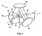
初めに図1を参照すると、ビーム・ミキサー10はビーム12(例示のために、上部の白半分及び下部の黒半分を有するように示される)に作用するように示される。以下に詳細に説明するように、ビーム・ミキサー10は、ビームの強度プロファイルを変えるため、例えば、ビームの選択された軸方向の強度の対称を向上させるために使用することができ、或いは、ビーム・コヒーレンシを減少させるため、又はそれら両方のために使用することができる。図示された実施形態に関しては、ビーム・ミキサー10はビーム・スプリッタ14及びミラー16a〜16cを含む。
Referring initially to FIG. 1, a
図1に示される配置では、ビームは最初にビーム・スプリッタ14に入射し、そこでビームの一部分が反射によりミラー16aの方向に向けられ、残り部分はビーム・スプリッタ14を透過(実質的に方向は変化しない)し、ビーム・ミキサーを出射して出力ビーム経路上に出る。1つのセットアップにおいて、入射光の約40乃至60パーセント、例えば、50パーセントを反射するビーム・スプリッタを使用することができる。このセットアップでは、ビーム・スプリッタ14に入射した最初のビームの約50パーセントがミラー16aの方向に向けられる。ビーム・ミキサー10に関しては、ミラー16a〜16cは、典型的には平面の、最大反射率のミラーである。図1に示されるように、ミラー16aは、ビーム・スプリッタ14からの光を約30度の入射角度で受けるように配置及び配向させることができる。さらに示されるように、ミラー16bは、ミラー16aから反射された光を約30度の入射角度で受けるように配置及び配向させることができ、ミラー16cは、ミラー16bから反射された光を約30度の入射角度で受けるように配置及び配向させることができる。
In the arrangement shown in FIG. 1, the beam first enters the beam splitter 14, where a portion of the beam is directed by reflection towards the mirror 16a and the remaining portion is transmitted through the beam splitter 14 (substantially in direction). Does not change) and exits the beam mixer and exits on the output beam path. In one setup, a beam splitter that reflects about 40 to 60 percent, eg, 50 percent, of the incident light can be used. In this setup, about 50 percent of the first beam incident on the beam splitter 14 is directed toward the mirror 16a. For
引き続き図1を参照すると、ミラー16cから反射された光は、約45度の入射角度でビーム・スプリッタ14に入射する。50パーセント反射率のビーム・スプリッタに関しては、図示されるように、ミラー16cからの光の約半分が出力ビーム経路上へ反射され、ミラー16cからの光の約半分がビーム・スプリッタを透過してミラー16aに向かうビーム経路上に出る。従って、出力ビーム経路は、初めのビーム12のビーム・スプリッタ14を透過した部分、及び、ミラー16cからの光のビーム・スプリッタ14から反射された部分を含む結合されたビームを含む。同様に、ビーム・スプリッタ14からミラー16aに至る経路上の光は、初めのビーム12のビーム・スプリッタ14によって反射された部分、及び、ミラー16cからの光のビーム・スプリッタ14を透過した部分を含む結合されたビームを含む。
Still referring to FIG. 1, the light reflected from the
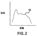
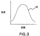
図1においてビーム・ミキサー10に入射するビームは、長軸18を定める長方形の断面を有するように示されている。この型のビームは、エキシマ・レーザによって生成されるレーザ・ビームの典型であり、長軸は一方の放電電極から他方に向う方向に対応する。典型的なビームは約3mm×12mmの大きさを有することができる。さらに、エキシマ・レーザの出力に対して、長軸18方向の強度プロファイルは普通、非対称(図2のグラフ50を参照)であり、一方、短軸(即ち、長軸に対して垂直な軸)方向の強度プロファイルは、概ねガウス形である(図3のグラフ52を参照)。図示されたビーム・ミキサー10は高出力エキシマ放電レーザの対称性を向上させるのに特に適しているが、これは他の型のレーザ・システムと共に及び他の用途に使用できること、例えば、このビーム・ミキサーは固体レーザによって生成されるビームのコヒーレンシを減少させるのに使用できることを認識されたい。
In FIG. 1, the beam incident on
図1は、ビームが第1の端20から第2の端22まで軸18に沿って広がることを示す。図1はまた、ミラー16a〜16cが始点24及び終点26を有する空間的な反転経路を設定することを示す。図1に示されるように、反転経路は、反転経路の始点24における第1のビーム端20の近くのビームの一部分が反転経路の終点26における第2のビーム端に移動することで特徴付けることができる。より具体的には、図示されたミキサー10に関して、ミラー16aに入射するビームの「頂部」の光子はミラー16cに移動し、ビームの「底部」でミラー16cを出射する。反転経路は遅延経路を構成するので、パルスのある程度の一時的な伸びが存在することになるが、これは遅延経路を最小にすることによって最小化することができる。
FIG. 1 shows that the beam extends along
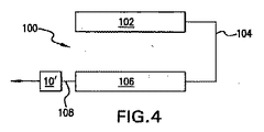
図4は、ビーム104を生成する発振器102と、ビーム104を受け取って増幅する増幅器106とを有するレーザ光源(一般的に100で示す)を示す。図4はまた、光源100は、上述のように、ビームの選択された軸方向の強度の対称性を向上させるためのビーム・ミキサー10´を含むことができることを示す。図示された配置において、増幅器106は増幅されたビーム108を出力し、この出力がビーム・ミキサー10´に供給される。光源100に関して、発振器は、KrFエキシマ・レーザ、XeFエキシマ・レーザ、ArFエキシマ・レーザ又はフッ素分子レーザのようなパルス気体放電レーザとすることができ、そして、1つ又はそれ以上の格子、プリズム、エタロンなどのような分散光学部品を使用して細幅にしたラインとしても又はそうしなくてもよい。キャビティ・ダンプ型レーザ、モードロック型又はQスポイル型のような他の型のレーザを使用することができる。発振器はパルス型又は連続型とすることができ、そして、CO2気体放電レーザ、色素レーザ、又は、例えばファイバ・レーザ、ダイオード・レーザなどのような固体レーザとすることができる。光源100に関して、増幅器はパルス型又は連続型とすることができ、そして、エキシマ・レーザ、フッ素分子レーザ、CO2気体放電レーザ、色素レーザ、又は、例えばファイバ・レーザ、ダイオード・レーザなどの固体レーザとすることができる。1つより多くの増幅器を直列又は並列に使用することができる。
FIG. 4 shows a laser light source (generally indicated at 100) having an
図5は、レーザ光源(一般的に200で示す)がシード・ビーム204を生成する発振器202及び増幅器206を有する別の実施形態を示す。図5はまた、光源200が、上述のように、シード・ビームの選択された軸方向の強度の対称性を向上させるための、ビーム・ミキサー10´´を含むことができることを示す。図示された配置において、発振器202はシード・ビーム204を出力し、これがビーム・ミキサー10´´に供給される。混合ビーム208は、次に、増幅器206に供給され、この増幅器がビーム208を増幅して増幅されたビーム210を出力する。
FIG. 5 shows another embodiment in which a laser light source (generally designated 200) has an
光源200に関して、発振器は、KrFエキシマ・レーザ、XeFエキシマ・レーザ、ArFエキシマ・レーザ又はフッ素分子レーザのようなパルス気体放電レーザとすることができ、そして、1つ又はそれ以上の格子、プリズム、エタロンなどのような分散光学部品を使用して細幅にしたラインとしても又はそうしなくてもよい。キャビティ・ダンプ型レーザ、モードロック型又はQスポイル型のような他の型のレーザを使用することができる。発振器は、パルス型又は連続型とすることができ、そして、CO2気体放電レーザ、色素レーザ、又は、例えばファイバ・レーザ、ダイオード・レーザなどの固体レーザとすることができる。光源200に関して、増幅器はパルス型又は連続型とすることができ、そして、エキシマ・レーザ、フッ素分子レーザ、CO2気体放電レーザ、色素レーザ、又は、例えばファイバ・レーザ、ダイオード・レーザなどの固体レーザとすることができる。1つより多くの増幅器を直列又は並列に使用することができる。
With respect to the
単一のビーム・ミキサー10´、10´´が図4及び図5に示されるが、ビームの選択された軸方向の強度プロファイルを変えるためには、2つのビーム・ミキサーを直列に使用して、第1のビーム・ミキサーがビームの第1の軸方向の強度プロファイルを変え、第2のビーム・ミキサーがビームの第2の軸方向の強度プロファイルを変えるようにすることが可能であることを認識されたい。例えば、第1の軸と第2の軸は直交することができる。 Single beam mixers 10 ', 10' 'are shown in FIGS. 4 and 5, but two beam mixers can be used in series to change the selected axial intensity profile of the beam. The first beam mixer can change the first axial intensity profile of the beam and the second beam mixer can change the second axial intensity profile of the beam. I want to be recognized. For example, the first axis and the second axis can be orthogonal.
米国特許法第112条を満たすように要求される本特許出願において詳細に説明され例証された実施形態の特定の態様は、上記の実施形態の態様により、又は何らかの理由でそのために、又はその目的で、解決されるべき問題に対して、何れかの上述の目的を完全に達成することができるが、当業者であれば、本発明の説明された実施形態のここで説明された態様は、本発明によって広く企図される対象物の例示的、例証的及び代表的なものにすぎないことを理解されたい。ここで説明され、及び特許請求される実施形態の態様の範囲は、本明細書の教示に基づけば当業者には明らかである、又は、明らかとなる他の実施形態を完全に包含する。本発明の範囲は、添付の特許請求の範囲のみによって単独で及び完全に限定され、そして、添付の特許請求の範囲の詳細を超えるものはない。それら請求項中の単数形の要素に対する言及は、明記しない限り、それら請求項の要素「1つ及び1つのみ」を意味することを意図せず、又はそのように解釈すべきではなく、むしろ「1つ又はそれ以上」を意味する。当業者には既知であるか又は後に既知となる、実施形態の上述の態様のあらゆる要素に対する全ての構造的及び機能的な同等物は、引用によりここに明白に組み込まれ、そして本特許請求の範囲によって包含されることが意図されている。本明細書及び/又は特許請求の範囲において使用され、そして本出願の本明細書及び/又は特許請求の範囲内において明白に意味を与えられたどの用語も、それら用語の如何なる辞書による又は他の通常に使用される意味には関わらず、その与えられた意味を有するものとする。実施形態の何らかの態様として本明細書で説明された装置又は方法は、本特許請求の範囲に包含されるべきものであり、本出願において開示された実施形態の態様により解決するために調べられた各々及び全ての問題を扱うことを意図したものではなく、或いはそれを必要とするものでもない。本開示におけるどの要素、構成要素又は方法ステップも、その要素、構成要素又は方法ステップが特許請求の範囲内に明確に説明されるかどうかに関わらず、公開のために意図したものではない。添付の特許請求の範囲内のどの特許請求の要素も、その要素が「のための手段」という句を使用して明白に説明されない限り、又は、方法の特許請求の場合において、要素が「行為」の代わりに「ステップ」として説明されない限り、米国特許法第112条第6項の条項の下で解釈されるべきではない。 Certain aspects of the embodiments described and illustrated in detail in this patent application that are required to satisfy 35 USC 112 may depend on, or for any reason, the aspects of the above embodiments. Thus, although any of the above objectives can be fully achieved for the problem to be solved, those skilled in the art will appreciate that the described aspects of the described embodiments of the invention are: It should be understood that this is merely exemplary, illustrative and representative of objects broadly contemplated by the present invention. The scope of aspects of the embodiments described and claimed herein will be apparent to those skilled in the art based on the teachings herein, or fully encompass other embodiments that will be apparent. The scope of the present invention is solely and completely limited by the appended claims, and nothing in any way exceeds the details of the appended claims. References to singular elements in the claims are not intended, nor should they be construed, to mean “one and only one” of the claims, unless stated otherwise. Means “one or more”. All structural and functional equivalents for any element of the above-described aspects of the embodiments that are known or later known to those skilled in the art are expressly incorporated herein by reference and are It is intended to be covered by a range. Any terms used in the specification and / or claims and expressly given meaning within the specification and / or claims of the present application are subject to any dictionary of such terms or other It shall have its given meaning regardless of the commonly used meaning. Any apparatus or method described herein as any aspect of an embodiment is intended to be included within the scope of the claims, and investigated to solve by aspects of the embodiments disclosed in this application. It is not intended to address or require each and every problem. No element, component, or method step in this disclosure is intended for publication regardless of whether that element, component, or method step is specifically described in the claims. Any claim element within the scope of the appended claims shall not be construed unless the element is expressly described using the phrase “means for” or in the case of a method claim. Should not be construed under the provisions of 35 USC 112, paragraph 6, unless stated as "steps" instead of "."
当業者であれば、上に開示された本発明の実施形態の態様は、好ましい実施形態にのみ向けられたものであり、本発明の開示を多少なりとも限定することを意図したものではなく、そして、特定の好ましい実施形態にだけ限定することを意図したものではないことを理解するであろう。多くの変形及び修正を、開示された本発明の実施形態の開示された態様に加えることができることは、当業者によって理解され認識されるであろう。添付の特許請求の範囲は、本発明の実施形態の開示された態様のみならず、当業者には明らかとなるそのような同等物及び他の修正物及び変形物をも範囲に含むことを意図したものであり、意味するものである。 Those skilled in the art will appreciate that the aspects of the embodiments of the invention disclosed above are directed to the preferred embodiments only and are not intended to limit the disclosure of the invention in any way. It will be understood that it is not intended to be limited to any particular preferred embodiment. It will be understood and appreciated by those skilled in the art that many variations and modifications can be made to the disclosed aspects of the disclosed embodiments of the invention. The appended claims are intended to cover not only the disclosed aspects of the embodiments of the present invention but also such equivalents and other modifications and variations that would be apparent to a person skilled in the art. Is what it means.
Claims (20)
空間的な反転経路を設定する複数のミラーであって、該空間的な反転経路は、始点及び終点を有し、該経路の該始点における前記第1のビーム端の近くの前記ビームの一部分が該経路の該終点における前記第2のビーム端に移動することで特徴付けられる、前記複数のミラーと、
前記ビームを第1及び第2のビーム部分に分割し、該第1の部分を前記反転経路上に配置し、前記第1の部分が前記反転経路に沿って進んだ後、前記第1及び第2の部分を共通経路上で再結合させて前記ビームを混合する、光学部品と、
を備えることを特徴とするビーム・ミキサー。 A beam mixer for improving beam intensity symmetry along a selected axis, the beam extending from a first end to a second end along the axis, the beam mixer comprising: ,
A plurality of mirrors that establish a spatial inversion path, the spatial inversion path having a start point and an end point, wherein a portion of the beam near the first beam end at the start point of the path is The plurality of mirrors characterized by moving to the second beam end at the end of the path;
The beam is divided into first and second beam portions, the first portion is disposed on the inversion path, and after the first portion travels along the inversion path, the first and second portions are arranged. An optical component that recombines the two parts on a common path and mixes the beam;
A beam mixer comprising:
前記ビームに沿った第1の位置における前記第1のビーム端の近くの前記ビームの一部分を、前記ビームに沿った第2の位置における前記第2のビーム端に移動させるための光学的な反転手段と、
前記ビームの第1の部分を前記反転手段の方に方向付け、第2の部分を共通ビーム経路に方向付け、及び、前記反転手段の出力を前記共通ビーム経路に方向つけるための手段と
を備えることを特徴とするビーム・ミキサー。 A beam mixer for changing the intensity profile of a beam along a selected axis, the beam extending from a first end to a second end along the axis, the beam mixer comprising:
Optical inversion to move a portion of the beam near the first beam end at a first position along the beam to the second beam end at a second position along the beam. Means,
Means for directing a first portion of the beam toward the reversing means, a second portion directing to a common beam path, and directing the output of the reversing means to the common beam path. This is a beam mixer.
前記ビームを増幅する増幅器と、
選択された軸に沿った前記ビームの強度の対称性を向上させるビーム・ミキサーと、
を備えることを特徴とするレーザ光源。 An oscillator that generates a beam;
An amplifier for amplifying the beam;
A beam mixer that improves symmetry of the intensity of the beam along a selected axis;
A laser light source comprising:
空間的な反転経路を設定する複数のミラーであって、該空間的な反転経路は、始点及び終点を有し、該経路の該始点における前記第1のビーム端の近くの前記ビームの一部分が該経路の該終点における前記第2のビーム端に移動することで特徴付けられる、前記複数のミラーと、
前記ビームを第1及び第2のビーム部分に分割し、該第1の部分を前記反転経路上に配置し、前記第1の部分が前記反転経路に沿って進んだ後、前記第1及び第2の部分を共通経路上で再結合させて前記ビームを混合する、光学部品と、
を備えることを特徴とする、請求項14に記載のレーザ光源。 The beam mixer is
A plurality of mirrors that establish a spatial inversion path, the spatial inversion path having a start point and an end point, wherein a portion of the beam near the first beam end at the start point of the path is The plurality of mirrors characterized by moving to the second beam end at the end of the path;
The beam is divided into first and second beam portions, the first portion is disposed on the inversion path, and after the first portion travels along the inversion path, the first and second portions are arranged. An optical component that recombines the two parts on a common path and mixes the beam;
The laser light source according to claim 14, comprising:
空間的な反転経路を設定する複数のミラーであって、該空間的な反転経路は、始点及び終点を有し、該経路の該始点における前記第1のビーム端の近くの前記ビームの一部分が該経路の該終点における前記第2のビーム端に移動することで特徴付けられる、前記複数のミラーと、
前記ビームを第1及び第2のビーム部分に分割し、該第1の部分を前記反転経路上に配置し、前記第1の部分が前記反転経路に沿って進んだ後、前記第1及び第2の部分を共通経路上で再結合させて前記ビームを混合する、光学部品と、
を備えることを特徴とする、請求項17に記載のレーザ光源。 The beam mixer is
A plurality of mirrors that establish a spatial inversion path, the spatial inversion path having a start point and an end point, wherein a portion of the beam near the first beam end at the start point of the path is The plurality of mirrors characterized by moving to the second beam end at the end of the path;
The beam is divided into first and second beam portions, the first portion is disposed on the inversion path, and after the first portion travels along the inversion path, the first and second portions are arranged. An optical component that recombines the two parts on a common path and mixes the beam;
The laser light source according to claim 17, comprising:
Applications Claiming Priority (2)
| Application Number | Priority Date | Filing Date | Title |
|---|---|---|---|
| US11/447,380 US7433372B2 (en) | 2006-06-05 | 2006-06-05 | Device and method to stabilize beam shape and symmetry for high energy pulsed laser applications |
| PCT/US2007/012389 WO2007145791A2 (en) | 2006-06-05 | 2007-05-22 | Device and method to stabilize beam shape and symmetry for high energy pulsed laser applications |
Publications (2)
| Publication Number | Publication Date |
|---|---|
| JP2009540567A true JP2009540567A (en) | 2009-11-19 |
| JP2009540567A5 JP2009540567A5 (en) | 2010-07-08 |
Family
ID=38789765
Family Applications (1)
| Application Number | Title | Priority Date | Filing Date |
|---|---|---|---|
| JP2009514300A Pending JP2009540567A (en) | 2006-06-05 | 2007-05-22 | Apparatus and method for stabilizing beam shape and symmetry for high energy pulsed laser applications |
Country Status (6)
| Country | Link |
|---|---|
| US (1) | US7433372B2 (en) |
| EP (1) | EP2036168B1 (en) |
| JP (1) | JP2009540567A (en) |
| KR (1) | KR101389722B1 (en) |
| TW (1) | TWI344014B (en) |
| WO (1) | WO2007145791A2 (en) |
Families Citing this family (16)
| Publication number | Priority date | Publication date | Assignee | Title |
|---|---|---|---|---|
| US7564888B2 (en) * | 2004-05-18 | 2009-07-21 | Cymer, Inc. | High power excimer laser with a pulse stretcher |
| US7643529B2 (en) * | 2005-11-01 | 2010-01-05 | Cymer, Inc. | Laser system |
| WO2007053335A2 (en) * | 2005-11-01 | 2007-05-10 | Cymer, Inc. | Laser system |
| US7715459B2 (en) * | 2005-11-01 | 2010-05-11 | Cymer, Inc. | Laser system |
| US20090296755A1 (en) * | 2005-11-01 | 2009-12-03 | Cymer, Inc. | Laser system |
| US7746913B2 (en) | 2005-11-01 | 2010-06-29 | Cymer, Inc. | Laser system |
| US20090296758A1 (en) * | 2005-11-01 | 2009-12-03 | Cymer, Inc. | Laser system |
| US7920616B2 (en) * | 2005-11-01 | 2011-04-05 | Cymer, Inc. | Laser system |
| US7999915B2 (en) * | 2005-11-01 | 2011-08-16 | Cymer, Inc. | Laser system |
| US7630424B2 (en) * | 2005-11-01 | 2009-12-08 | Cymer, Inc. | Laser system |
| US7885309B2 (en) * | 2005-11-01 | 2011-02-08 | Cymer, Inc. | Laser system |
| US7778302B2 (en) * | 2005-11-01 | 2010-08-17 | Cymer, Inc. | Laser system |
| US8803027B2 (en) * | 2006-06-05 | 2014-08-12 | Cymer, Llc | Device and method to create a low divergence, high power laser beam for material processing applications |
| WO2012120563A1 (en) * | 2011-03-08 | 2012-09-13 | パナソニック株式会社 | Thin film transistor array device, organic el display device, and method for manufacturing thin film transistor array device |
| KR102369090B1 (en) | 2015-09-15 | 2022-03-02 | 삼성디스플레이 주식회사 | Laser apparatus |
| KR20200120827A (en) | 2019-04-12 | 2020-10-22 | 삼성디스플레이 주식회사 | Laser apparatus and manufacturing method of display appratus using the same |
Citations (10)
| Publication number | Priority date | Publication date | Assignee | Title |
|---|---|---|---|---|
| JPS5042499A (en) * | 1973-08-21 | 1975-04-17 | ||
| JPH01319727A (en) * | 1988-06-22 | 1989-12-26 | Sony Corp | Optical device |
| JPH02166783A (en) * | 1988-12-21 | 1990-06-27 | Adomon Sci Kk | Homogenizer for excimer laser |
| JPH0990265A (en) * | 1995-09-26 | 1997-04-04 | Asahi Optical Co Ltd | Image reversing optical system |
| JPH11283933A (en) * | 1998-01-29 | 1999-10-15 | Toshiba Corp | Laser beam irradiating device, manufacture of non-single crystal semiconductor film, and manufacture of liquid crystal display device |
| JPH11312631A (en) * | 1998-04-27 | 1999-11-09 | Nikon Corp | Illuminating optical device and aligner |
| JPH11352419A (en) * | 1998-06-04 | 1999-12-24 | Sumitomo Heavy Ind Ltd | Homogenizer device with beam rotating function and laser beam machining device using it |
| JP2002139697A (en) * | 2000-11-02 | 2002-05-17 | Mitsubishi Electric Corp | Laser optical system using plural laser beams, and laser annealing apparatus |
| JP2002174767A (en) * | 2000-12-08 | 2002-06-21 | Mitsubishi Electric Corp | Laser optical system for laser treatment |
| JP2005502211A (en) * | 2001-08-29 | 2005-01-20 | サイマー インコーポレイテッド | Laser lithography light source with beam delivery |
Family Cites Families (6)
| Publication number | Priority date | Publication date | Assignee | Title |
|---|---|---|---|---|
| US6693930B1 (en) * | 2000-12-12 | 2004-02-17 | Kla-Tencor Technologies Corporation | Peak power and speckle contrast reduction for a single laser pulse |
| US7167499B2 (en) * | 2001-04-18 | 2007-01-23 | Tcz Pte. Ltd. | Very high energy, high stability gas discharge laser surface treatment system |
| US7009140B2 (en) * | 2001-04-18 | 2006-03-07 | Cymer, Inc. | Laser thin film poly-silicon annealing optical system |
| US20050259709A1 (en) * | 2002-05-07 | 2005-11-24 | Cymer, Inc. | Systems and methods for implementing an interaction between a laser shaped as a line beam and a film deposited on a substrate |
| US6928093B2 (en) * | 2002-05-07 | 2005-08-09 | Cymer, Inc. | Long delay and high TIS pulse stretcher |
| US7326948B2 (en) * | 2005-08-15 | 2008-02-05 | Asml Netherlands B.V. | Beam modifying device, lithographic projection apparatus, method of treating a beam, and device manufacturing method |
-
2006
- 2006-06-05 US US11/447,380 patent/US7433372B2/en active Active
-
2007
- 2007-05-14 TW TW096117040A patent/TWI344014B/en active
- 2007-05-22 JP JP2009514300A patent/JP2009540567A/en active Pending
- 2007-05-22 KR KR1020087030013A patent/KR101389722B1/en active IP Right Grant
- 2007-05-22 EP EP07809174.1A patent/EP2036168B1/en not_active Ceased
- 2007-05-22 WO PCT/US2007/012389 patent/WO2007145791A2/en active Application Filing
Patent Citations (10)
| Publication number | Priority date | Publication date | Assignee | Title |
|---|---|---|---|---|
| JPS5042499A (en) * | 1973-08-21 | 1975-04-17 | ||
| JPH01319727A (en) * | 1988-06-22 | 1989-12-26 | Sony Corp | Optical device |
| JPH02166783A (en) * | 1988-12-21 | 1990-06-27 | Adomon Sci Kk | Homogenizer for excimer laser |
| JPH0990265A (en) * | 1995-09-26 | 1997-04-04 | Asahi Optical Co Ltd | Image reversing optical system |
| JPH11283933A (en) * | 1998-01-29 | 1999-10-15 | Toshiba Corp | Laser beam irradiating device, manufacture of non-single crystal semiconductor film, and manufacture of liquid crystal display device |
| JPH11312631A (en) * | 1998-04-27 | 1999-11-09 | Nikon Corp | Illuminating optical device and aligner |
| JPH11352419A (en) * | 1998-06-04 | 1999-12-24 | Sumitomo Heavy Ind Ltd | Homogenizer device with beam rotating function and laser beam machining device using it |
| JP2002139697A (en) * | 2000-11-02 | 2002-05-17 | Mitsubishi Electric Corp | Laser optical system using plural laser beams, and laser annealing apparatus |
| JP2002174767A (en) * | 2000-12-08 | 2002-06-21 | Mitsubishi Electric Corp | Laser optical system for laser treatment |
| JP2005502211A (en) * | 2001-08-29 | 2005-01-20 | サイマー インコーポレイテッド | Laser lithography light source with beam delivery |
Also Published As
| Publication number | Publication date |
|---|---|
| KR101389722B1 (en) | 2014-04-29 |
| EP2036168A4 (en) | 2011-07-13 |
| EP2036168A2 (en) | 2009-03-18 |
| WO2007145791A2 (en) | 2007-12-21 |
| US20070279747A1 (en) | 2007-12-06 |
| US7433372B2 (en) | 2008-10-07 |
| EP2036168B1 (en) | 2019-07-03 |
| KR20090015962A (en) | 2009-02-12 |
| WO2007145791A3 (en) | 2008-03-13 |
| TWI344014B (en) | 2011-06-21 |
| TW200804869A (en) | 2008-01-16 |
Similar Documents
| Publication | Publication Date | Title |
|---|---|---|
| JP2009540567A (en) | Apparatus and method for stabilizing beam shape and symmetry for high energy pulsed laser applications | |
| US8265109B2 (en) | Systems and methods for implementing an interaction between a laser shaped as line beam and a film deposited on a substrate | |
| JP5231234B2 (en) | System for generating laser light shaped as a line beam | |
| US7277188B2 (en) | Systems and methods for implementing an interaction between a laser shaped as a line beam and a film deposited on a substrate | |
| US7615722B2 (en) | Amorphous silicon crystallization using combined beams from optically pumped semiconductor lasers | |
| US7418172B2 (en) | Beam homogenizer, laser irradiation apparatus, and method for manufacturing semiconductor device | |
| US7594965B2 (en) | Beam homogenizer and laser irradiation apparatus and method of manufacturing semiconductor device | |
| JP5107929B2 (en) | System and method for shaping laser light as a uniform line beam for interaction with a film deposited on a substrate | |
| US8803027B2 (en) | Device and method to create a low divergence, high power laser beam for material processing applications | |
| JP5590086B2 (en) | System and method for realizing interaction between a laser shaped as a line beam and a film deposited on a substrate | |
| KR20240005864A (en) | Method and apparatus for laser annealing | |
| US20070278193A1 (en) | Device and method to create a low divergence, high power laser beam for material processing applications | |
| JPH11352420A (en) | Homogenizer device with beam rotating function and laser beam machining device using it | |
| US20070205185A1 (en) | Laser exposure apparatus and laser annealing apparatus |
Legal Events
| Date | Code | Title | Description |
|---|---|---|---|
| A521 | Written amendment |
Free format text: JAPANESE INTERMEDIATE CODE: A523 Effective date: 20100521 |
|
| A621 | Written request for application examination |
Free format text: JAPANESE INTERMEDIATE CODE: A621 Effective date: 20100521 |
|
| A977 | Report on retrieval |
Free format text: JAPANESE INTERMEDIATE CODE: A971007 Effective date: 20120912 |
|
| A131 | Notification of reasons for refusal |
Free format text: JAPANESE INTERMEDIATE CODE: A131 Effective date: 20120918 |
|
| A601 | Written request for extension of time |
Free format text: JAPANESE INTERMEDIATE CODE: A601 Effective date: 20121218 |
|
| A602 | Written permission of extension of time |
Free format text: JAPANESE INTERMEDIATE CODE: A602 Effective date: 20121226 |
|
| A521 | Written amendment |
Free format text: JAPANESE INTERMEDIATE CODE: A523 Effective date: 20130118 |
|
| A131 | Notification of reasons for refusal |
Free format text: JAPANESE INTERMEDIATE CODE: A131 Effective date: 20130422 |
|
| A601 | Written request for extension of time |
Free format text: JAPANESE INTERMEDIATE CODE: A601 Effective date: 20130719 |
|
| A602 | Written permission of extension of time |
Free format text: JAPANESE INTERMEDIATE CODE: A602 Effective date: 20130726 |
|
| A601 | Written request for extension of time |
Free format text: JAPANESE INTERMEDIATE CODE: A601 Effective date: 20130822 |
|
| A602 | Written permission of extension of time |
Free format text: JAPANESE INTERMEDIATE CODE: A602 Effective date: 20130829 |
|
| A521 | Written amendment |
Free format text: JAPANESE INTERMEDIATE CODE: A523 Effective date: 20130924 |
|
| A131 | Notification of reasons for refusal |
Free format text: JAPANESE INTERMEDIATE CODE: A131 Effective date: 20140210 |
|
| A521 | Written amendment |
Free format text: JAPANESE INTERMEDIATE CODE: A523 Effective date: 20140512 |
|
| A02 | Decision of refusal |
Free format text: JAPANESE INTERMEDIATE CODE: A02 Effective date: 20140623 |
|
| A711 | Notification of change in applicant |
Free format text: JAPANESE INTERMEDIATE CODE: A712 Effective date: 20140704 |