JP2009540527A - Electrical connector with air circulation and polarization characteristics - Google Patents
Electrical connector with air circulation and polarization characteristics Download PDFInfo
- Publication number
- JP2009540527A JP2009540527A JP2009515407A JP2009515407A JP2009540527A JP 2009540527 A JP2009540527 A JP 2009540527A JP 2009515407 A JP2009515407 A JP 2009515407A JP 2009515407 A JP2009515407 A JP 2009515407A JP 2009540527 A JP2009540527 A JP 2009540527A
- Authority
- JP
- Japan
- Prior art keywords
- power contact
- cavity
- housing
- electrical connector
- power
- Prior art date
- Legal status (The legal status is an assumption and is not a legal conclusion. Google has not performed a legal analysis and makes no representation as to the accuracy of the status listed.)
- Withdrawn
Links
Images


Classifications
-
- H—ELECTRICITY
- H01—ELECTRIC ELEMENTS
- H01R—ELECTRICALLY-CONDUCTIVE CONNECTIONS; STRUCTURAL ASSOCIATIONS OF A PLURALITY OF MUTUALLY-INSULATED ELECTRICAL CONNECTING ELEMENTS; COUPLING DEVICES; CURRENT COLLECTORS
- H01R13/00—Details of coupling devices of the kinds covered by groups H01R12/70 or H01R24/00 - H01R33/00
- H01R13/64—Means for preventing incorrect coupling
-
- H—ELECTRICITY
- H01—ELECTRIC ELEMENTS
- H01R—ELECTRICALLY-CONDUCTIVE CONNECTIONS; STRUCTURAL ASSOCIATIONS OF A PLURALITY OF MUTUALLY-INSULATED ELECTRICAL CONNECTING ELEMENTS; COUPLING DEVICES; CURRENT COLLECTORS
- H01R12/00—Structural associations of a plurality of mutually-insulated electrical connecting elements, specially adapted for printed circuits, e.g. printed circuit boards [PCB], flat or ribbon cables, or like generally planar structures, e.g. terminal strips, terminal blocks; Coupling devices specially adapted for printed circuits, flat or ribbon cables, or like generally planar structures; Terminals specially adapted for contact with, or insertion into, printed circuits, flat or ribbon cables, or like generally planar structures
- H01R12/70—Coupling devices
- H01R12/7088—Arrangements for power supply
-
- H—ELECTRICITY
- H01—ELECTRIC ELEMENTS
- H01R—ELECTRICALLY-CONDUCTIVE CONNECTIONS; STRUCTURAL ASSOCIATIONS OF A PLURALITY OF MUTUALLY-INSULATED ELECTRICAL CONNECTING ELEMENTS; COUPLING DEVICES; CURRENT COLLECTORS
- H01R12/00—Structural associations of a plurality of mutually-insulated electrical connecting elements, specially adapted for printed circuits, e.g. printed circuit boards [PCB], flat or ribbon cables, or like generally planar structures, e.g. terminal strips, terminal blocks; Coupling devices specially adapted for printed circuits, flat or ribbon cables, or like generally planar structures; Terminals specially adapted for contact with, or insertion into, printed circuits, flat or ribbon cables, or like generally planar structures
- H01R12/50—Fixed connections
- H01R12/51—Fixed connections for rigid printed circuits or like structures
-
- H—ELECTRICITY
- H01—ELECTRIC ELEMENTS
- H01R—ELECTRICALLY-CONDUCTIVE CONNECTIONS; STRUCTURAL ASSOCIATIONS OF A PLURALITY OF MUTUALLY-INSULATED ELECTRICAL CONNECTING ELEMENTS; COUPLING DEVICES; CURRENT COLLECTORS
- H01R12/00—Structural associations of a plurality of mutually-insulated electrical connecting elements, specially adapted for printed circuits, e.g. printed circuit boards [PCB], flat or ribbon cables, or like generally planar structures, e.g. terminal strips, terminal blocks; Coupling devices specially adapted for printed circuits, flat or ribbon cables, or like generally planar structures; Terminals specially adapted for contact with, or insertion into, printed circuits, flat or ribbon cables, or like generally planar structures
- H01R12/70—Coupling devices
- H01R12/71—Coupling devices for rigid printing circuits or like structures
- H01R12/712—Coupling devices for rigid printing circuits or like structures co-operating with the surface of the printed circuit or with a coupling device exclusively provided on the surface of the printed circuit
- H01R12/716—Coupling device provided on the PCB
-
- H—ELECTRICITY
- H01—ELECTRIC ELEMENTS
- H01R—ELECTRICALLY-CONDUCTIVE CONNECTIONS; STRUCTURAL ASSOCIATIONS OF A PLURALITY OF MUTUALLY-INSULATED ELECTRICAL CONNECTING ELEMENTS; COUPLING DEVICES; CURRENT COLLECTORS
- H01R12/00—Structural associations of a plurality of mutually-insulated electrical connecting elements, specially adapted for printed circuits, e.g. printed circuit boards [PCB], flat or ribbon cables, or like generally planar structures, e.g. terminal strips, terminal blocks; Coupling devices specially adapted for printed circuits, flat or ribbon cables, or like generally planar structures; Terminals specially adapted for contact with, or insertion into, printed circuits, flat or ribbon cables, or like generally planar structures
- H01R12/70—Coupling devices
- H01R12/71—Coupling devices for rigid printing circuits or like structures
- H01R12/72—Coupling devices for rigid printing circuits or like structures coupling with the edge of the rigid printed circuits or like structures
- H01R12/722—Coupling devices for rigid printing circuits or like structures coupling with the edge of the rigid printed circuits or like structures coupling devices mounted on the edge of the printed circuits
- H01R12/724—Coupling devices for rigid printing circuits or like structures coupling with the edge of the rigid printed circuits or like structures coupling devices mounted on the edge of the printed circuits containing contact members forming a right angle
-
- H—ELECTRICITY
- H01—ELECTRIC ELEMENTS
- H01R—ELECTRICALLY-CONDUCTIVE CONNECTIONS; STRUCTURAL ASSOCIATIONS OF A PLURALITY OF MUTUALLY-INSULATED ELECTRICAL CONNECTING ELEMENTS; COUPLING DEVICES; CURRENT COLLECTORS
- H01R12/00—Structural associations of a plurality of mutually-insulated electrical connecting elements, specially adapted for printed circuits, e.g. printed circuit boards [PCB], flat or ribbon cables, or like generally planar structures, e.g. terminal strips, terminal blocks; Coupling devices specially adapted for printed circuits, flat or ribbon cables, or like generally planar structures; Terminals specially adapted for contact with, or insertion into, printed circuits, flat or ribbon cables, or like generally planar structures
- H01R12/70—Coupling devices
- H01R12/71—Coupling devices for rigid printing circuits or like structures
- H01R12/72—Coupling devices for rigid printing circuits or like structures coupling with the edge of the rigid printed circuits or like structures
- H01R12/73—Coupling devices for rigid printing circuits or like structures coupling with the edge of the rigid printed circuits or like structures connecting to other rigid printed circuits or like structures
- H01R12/735—Printed circuits including an angle between each other
- H01R12/737—Printed circuits being substantially perpendicular to each other
-
- H—ELECTRICITY
- H01—ELECTRIC ELEMENTS
- H01R—ELECTRICALLY-CONDUCTIVE CONNECTIONS; STRUCTURAL ASSOCIATIONS OF A PLURALITY OF MUTUALLY-INSULATED ELECTRICAL CONNECTING ELEMENTS; COUPLING DEVICES; CURRENT COLLECTORS
- H01R13/00—Details of coupling devices of the kinds covered by groups H01R12/70 or H01R24/00 - H01R33/00
- H01R13/40—Securing contact members in or to a base or case; Insulating of contact members
- H01R13/42—Securing in a demountable manner
-
- H—ELECTRICITY
- H01—ELECTRIC ELEMENTS
- H01R—ELECTRICALLY-CONDUCTIVE CONNECTIONS; STRUCTURAL ASSOCIATIONS OF A PLURALITY OF MUTUALLY-INSULATED ELECTRICAL CONNECTING ELEMENTS; COUPLING DEVICES; CURRENT COLLECTORS
- H01R13/00—Details of coupling devices of the kinds covered by groups H01R12/70 or H01R24/00 - H01R33/00
- H01R13/64—Means for preventing incorrect coupling
- H01R13/642—Means for preventing incorrect coupling by position or shape of contact members
-
- H—ELECTRICITY
- H01—ELECTRIC ELEMENTS
- H01R—ELECTRICALLY-CONDUCTIVE CONNECTIONS; STRUCTURAL ASSOCIATIONS OF A PLURALITY OF MUTUALLY-INSULATED ELECTRICAL CONNECTING ELEMENTS; COUPLING DEVICES; CURRENT COLLECTORS
- H01R13/00—Details of coupling devices of the kinds covered by groups H01R12/70 or H01R24/00 - H01R33/00
- H01R13/648—Protective earth or shield arrangements on coupling devices, e.g. anti-static shielding
Abstract
【解決手段】 電気コネクタの実施例は、電気コネクタを通って、かつその電気コネクタの周りで空気の循環を促進する特徴を有している。この空気は、その電気コネクタの電力接点を冷却することができ、それによって、その電力接点が、そうでなければ可能であるよりも高い電流で作動することを可能にしている。その接点は、分極化されて、ハウジングにおける接点の不適当な、または不完全な挿入を防ぐことを支援する。
【選択図】 図17An embodiment of an electrical connector has features that facilitate air circulation through and around the electrical connector. This air can cool the power contacts of the electrical connector, thereby allowing the power contacts to operate at a higher current than would otherwise be possible. The contacts are polarized to help prevent improper or incomplete insertion of the contacts in the housing.
[Selection] Figure 17
Description
この発明は、電力を伝送するための電気コネクタに関する。 The present invention relates to an electrical connector for transmitting electric power.
一般に、電子装置の動作電流を増加させることは、その装置がそうでなければ可能であるよりも低い電圧で作動することを可能にする。したがって、電子装置のメーカーは、比較的高い定格電流を有する電力接点を要請するか、または、要求することがある。その結果、作動中に電力接点が経験した温度上昇を最小限にすることが望ましい。 In general, increasing the operating current of an electronic device allows the device to operate at a lower voltage than would otherwise be possible. Thus, electronic device manufacturers may or may require power contacts having a relatively high rated current. As a result, it is desirable to minimize the temperature rise experienced by the power contacts during operation.
コネクタハウジング内に接点を組立てることは、さらに問題となり得る。接点は、不適切な空洞内に挿入され得、または、空洞内に単に部分的に挿入され得る。 Assembling the contacts within the connector housing can be a further problem. The contacts can be inserted into an improper cavity, or simply partially inserted into the cavity.
電気コネクタの実施例は、この電気コネクタを通って、かつその周りで空気の循環を促進する特徴を有する。この空気は、その電気コネクタの電力接点を冷却することができ、それによって、その電力接点が、そうでなければ可能であるよりも高い電流で作動することを可能にしている。特徴は、さらにハウジング内への接点の誤挿入または部分的な挿入を防止するのを支援するために有している。 Embodiments of the electrical connector have features that facilitate air circulation through and around the electrical connector. This air can cool the power contacts of the electrical connector, thereby allowing the power contacts to operate at a higher current than would otherwise be possible. The feature further has to help prevent accidental or partial insertion of contacts into the housing.
コネクタ装置の実施例は、空洞を画定する電気絶縁ハウジングを有する第1の電気コネクタを有する。このハウジングは、その第1の電気コネクタの周りの周囲との流体伝達内(in fluid communication with the environment)にその空洞を置く、そこに形成された孔を有する。第1の電気コネクタは、さらに空洞内に位置された組合う部分を備えた電力接点を有する。 An embodiment of the connector device has a first electrical connector having an electrically insulating housing that defines a cavity. The housing has a hole formed therein that places the cavity in fluid communication with the environment around the first electrical connector. The first electrical connector further has a power contact with a mating portion located in the cavity.
このコネクタ装置は、さらに第1の電気コネクタと組合う第2の電気コネクタを有する。第2の電気コネクタは、空洞を画定する電気絶縁ハウジングを有する。第2の電気コネクタのハウジングは、また、この第2の電気コネクタの周りでその周囲との流体的伝達内にその第2の電気コネクタの空洞を置いてそこに形成された孔を有する。この第2の電気コネクタは、さらに、この第2の電気コネクタのハウジングの空洞内に位置する組合う部分を備えた電力接点を有する。 The connector device further includes a second electrical connector that is combined with the first electrical connector. The second electrical connector has an electrically insulating housing that defines a cavity. The housing of the second electrical connector also has a hole formed therein that places the cavity of the second electrical connector in fluid communication with and around the second electrical connector. The second electrical connector further has power contacts with mating portions located within the cavity of the housing of the second electrical connector.
第1および第2の電気コネクタが組合うときには、第1および第2の電気コネクタのハウジング内に形成された孔は、部分的に一致する(overlap)。 When the first and second electrical connectors are combined, the holes formed in the housings of the first and second electrical connectors partially overlap.
基板に設置するための電気コネクタの実施例は、電力接点およびこの電力接点を受入れる電気絶縁ハウジングを有する。孔が、そのハウジングに形成される。この孔は、電力接点によって加熱された空気が、孔を通って電力接点を出ることができる電力接点の組合う部分と整列される。凹部が、ハウジングに形成される。この凹部は、基板に面しており、さらに、凹部と基板とは、電気コネクタが基板に設置されるときに、ハウジングの側部から延びる通路を画定する。電力接点の部分は、凹部を通して延び、それによって電気コネクタの周りの周囲からの空気が、ハウジングと基板との間に、しかも電力接点の上を越えて通ることができる。 An embodiment of an electrical connector for installation on a substrate has a power contact and an electrically insulating housing that receives the power contact. A hole is formed in the housing. The holes are aligned with the mating portions of the power contacts that allow the air heated by the power contacts to exit the power contacts through the holes. A recess is formed in the housing. The recess faces the substrate, and the recess and the substrate further define a passage extending from the side of the housing when the electrical connector is installed on the substrate. The portion of the power contact extends through the recess so that air from the periphery around the electrical connector can pass between the housing and the substrate and over the power contact.
電気コネクタの実施例は、電気絶縁ハウジング、および、このハウジングに設置され、組合う部分を有する電力接点を有する。このハウジングは、そこに形成され、かつ、電力接点によって加熱された空気がその孔を通って電力接点を出ることができる接点の組合う部分と整列する孔を有する。 An embodiment of the electrical connector has an electrically insulating housing and a power contact with a mating portion installed in the housing. The housing has holes formed therein and aligned with mating portions of the contacts through which air heated by the power contacts can exit the power contacts.
電気コネクタの実施例は、ハウジングと、2つの異なるタイプの電力接点とを有する。この電力接点は、電力接点がハウジングに不適切に設置される可能性を縮小するか、または除去する、分極化する(polarization)特徴を有する。 Examples of electrical connectors have a housing and two different types of power contacts. This power contact has a polarization feature that reduces or eliminates the possibility of the power contact being improperly installed in the housing.
電気コネクタの実施例は、タブを有する第1の電力接点と、タブを有する第2の電力接点と、その中にそれぞれ第1および第2の電力接点を受入れるように形成された第1および第2の空洞を有するハウジングとを有する。第1の電力接点のタブは、第2の空洞における第1の電力接点の設置を防止することによって、第1の電力接点が第2の空洞内に部分的に挿入されるときに、第1の電力接点のタブは、ハウジングと干渉するように(interferedly)接触する。第1の空洞における第2の電力接点の設置を防止することによって、第2の電力接点が、第1の空洞内に部分的に挿入されるときに、第2の電力接点のタブは、ハウジングと干渉するように接触する。 An embodiment of the electrical connector includes a first power contact having a tab, a second power contact having a tab, and first and second power contacts formed therein to receive first and second power contacts, respectively. And a housing having two cavities. The tab of the first power contact prevents the first power contact from being installed in the second cavity so that the first power contact is partially inserted into the second cavity when the first power contact is partially inserted into the second cavity. The power contact tabs interferedly contact the housing. By preventing the installation of the second power contact in the first cavity, when the second power contact is partially inserted into the first cavity, the tab of the second power contact is in the housing. Contact to interfere with.
図1〜12は、コプラナーコネクタ装置10の一実施例を描いている。その図は、そこに描かれた共通座標系(common coordinate system)11に参照される。コネクタ装置10は、ヘッダーコネクタ12と、このヘッダーコネクタ12と組合うレセプタクルコネクタ14とを有する。このヘッダーコネクタ12は、印刷回路基板(PCB)16のような基板に設置することができ、また、そのレセプタクルコネクタ14は、PCB18のような基板に設置することができる。ヘッダーコネクタ12およびレセプタクルコネクタ14は、組合ったときに、PCB16とPCB18とを電気的に接続する。
1-12 depict one embodiment of a
ヘッダーコネクタ12は、電気絶縁ハウジング22と、このハウジング22に設置される複数の電力接点24とを有する。図11に示されるように、各電力接点24は、第1の半片(half)26と第2の半片28とを有する。この第1の半片26は、プレート状の本体部材30aと、この本体部材30aの下方端に隣接するほぼS形部分31とを有する。第1の半片26は、さらに、このS形部分31の下方端からそれぞれ延びる複数の端子ピン32を有する。
The
第1の半片26は、さらに、本体部分30aの前方端からそれぞれ延びる3つの、角度のある接点ビーム34aと2つのほぼ直線の接点ビーム36aとを有する。この角度のある接点ビーム34aおよび直線の接点ビーム36aは、互い違い方式(staggered manner)で本体部材30aに配置される、換言すれば、各直線の接点ビーム36aは、角度のある接点ビーム34aのうちの2つに隣接して配置されている。
The
「上方の」、「下方の」、「前方の」、「後方の」、「頂」」、「底」、「上部の」、「下部の」などのような、方向性の用語は、図1に描かれた部品の方向に関して使用される。これらの用語は、代表的な目的にのみ使用され、かつ、付属の請求項の範囲を制限するようには意図されていない。 Directional terms such as “upper”, “lower”, “front”, “backward”, “top”, “bottom”, “top”, “bottom”, etc. Used with respect to the orientation of the part depicted in FIG. These terms are used for representative purposes only and are not intended to limit the scope of the appended claims.
各電力接点24の第2の半片28は、本体部材30bの下方端に隣接する、プレート状の本体部材30bと他のS形部分31とを有している。この第2の半片28は、さらにS形部分31の下方端からそれぞれ延びる複数の端子ピン32を有している。
The
第2の半片28は、さらに、本体部材30bの前方端からそれぞれ延びる3つの角度のある接点ビーム34bと2つのほぼ直線の接点ビーム36bとを有する。図11に示されるように、角度のある接点ビーム34bと直線の接点ビーム36bとは、互い違い方式で本体部材30bに配置される。
The
本体部材30a、30bは、図11に示されるように、相互に対して重ね合わせられ、その結果、各角度のある接点ビーム34aは対面し、かつ、関連する角度のある接点ビーム34bから離れて間隔をもって配置され、また、各直線の接点ビーム36aは、関連する接点ビーム36bに対面し、かつ当接する。本体部材30a、30bが、重ね合わされるときに、S形部分31は、第1の半片26の端子ピン32と第2の半片28の端子ピン32との間のオフセットを提供する。
各本体部材30a、30bは、その上部後方の角部に位置されたタブ42を有することができる。図11に描かれるように、タブ42は外方に角度を有する。各タブ42は、電力接点24がその後方端からハウジング22内に挿入されるとともに、ハウジング22における関連するリップ(図示せず)と接触することができる。このタブ42とリップとの間の接触は、タブ42を内方に偏向させる。タブ42は、電力接点24がハウジング22内にその完全に挿入された位置に接近するので、そのリップを取り除く(clear)。一旦タブ42がリップを取り除くと、タブ42の弾性は、そのタブ42がその元の位置に対して、外方に弾むようにされる。タブ42とリップとの間の干渉は、ハウジング22から後退する(backing up)から、電力接点24を阻止する(discourage)ことができる。
The
Each
電力接点24の特定の詳細は、代表的な目的のためだけに開示されている。この発明の本質は、上記に相互参照された関連する出願に記述された電力接点を有する他のタイプの電力接点を有するコネクタに適用することができる。
Specific details of the
図1〜4に示されるように、ハウジング22は、主本体43と隣接する組合う部分44を有する。主本体43は、図1および3に示されるように、そこに形成された複数の空洞45を有する。各空洞45は、関連する電力接点24の本体部材30a、30bを受入れる。空洞45は、それぞれ、ハウジング22のリブ46によって部分的に画定される。このリブ46は、対向する組内に配置される。リブ46は、電力接点24が空洞45内に摺動されるので、関連する電力接点24の本体部材30aまたは30bと接触する。リブ46と本体部材30a、30bとの間の干渉は、本体部材30a、30bを一緒に押し、かつ、空洞45内に電力接点24を保持するのを助ける。
As shown in FIGS. 1 to 4, the
図1および3に描かれているように、リブ46は、その間に溝48を画定する。この溝48は、以下に議論されるように、ヘッダーコネクタ12の作動中に電力接点24からの熱伝達を促進する。
As depicted in FIGS. 1 and 3, the
ハウジング22の主本体43は、前方壁52を有する。この前方壁52は、図4において、部分的に描かれている。空洞45は、前方壁52を介して延び、その結果、電力接点24の、角度のある接点ビーム34a、34bおよび直線の接点ビーム36a、36bは、電力接点24がその後方端からハウジング22内に挿入されるときに、前方壁52を通過することができる。
The
図1−4および9に示されるように、ハウジング22の組合う部分44は、頂部56、底部58、および側部60、62を有する。図4に描かれているように、頂部56、底部58、側部60、62、および前壁52は、組合う区域または空洞64を画定する。この空洞64は、主本体43の空洞45に隣接する。図1〜4および9に示されるように、ヘッダーコネクタ12がそれに設置されるときに、組合う部分44は、PCB16の前方端に突き出る(overhang)。
1-4 and 9, the
電力接点24の角度のある接点ビーム34a、34bおよび直線の接点ビーム36a、36bは、図4に描かれているように、空洞64内に延びる。以下に議論されるように、ヘッダーとレセプタクルコネクタ12、14が組合うときに、空洞64は、レセプタクルコネクタ14の部分を受入れる。
ヘッダーコネクタ12は、信号接点70のアレイ68を有することができる。図4に示されるように、アレイ68は、電力接点24の一側面に位置することができる。アレイ70の部分は、図3に示されるように、ハウジング22に形成された空洞71内に位置することができる。このアレイ70は、ヘッダーコネクタ12の他の実施例において、電力接点24の間で、ヘッダーコネクタ12の中心に、またはその中心の近くに位置することができる。その他の別の実施例は、任意の信号接点の使用をやめることができる。
The
図1−4に示されるように、ハウジング22の主本体43は、頂部75、底部76、および側部77、78を有する。図1、3、4、5および7に示されるように、複数の細長のスロット、または孔80は、好ましくは、頂部75に形成される。各孔80は、関連する電力接点24の本体部分30a、30bの上に位置する。この孔80は、横方向に、または、ハウジング22の「z」方向に延びる。
As shown in FIGS. 1-4, the
孔80は、それぞれ、関連する空洞45に隣接し、それによってヘッダーコネクタ12の周りの周囲との流体伝達内に空洞45を置く。好ましくは、各孔80の幅、または「x」寸法は、関連する電力接点24の本体部分30a、30bの結合した幅、または、「x」寸法と同じ大きさか、または、より大きい。
The
図1、3、4、5および7に示されるように、追加の孔82が、好ましくは、その後方端に近接して、主本体43の頂部75に形成される。図5および7に示されるように、各孔82は、関連する空洞45に隣接し、関連する電力接点24のタブ42の上に位置する。孔82は、ヘッダーコネクタ12の周りの周囲との流体伝達内に空洞45の後方端を置く。好ましくは、各孔82の幅、または、「x」寸法は、関連する電力接点24のタブ42の先端(tip-to-tip)幅と等しいか、または、より大きい。
As shown in FIGS. 1, 3, 4, 5 and 7, an
図1および3−8に示されるように、孔84は、組合う部分44の頂部56に形成される。この孔84は、空洞64に隣接する。各孔84は、関連する電力接点24の角度のある接点ビーム34a、34b、および直線の接点ビーム36a、36bの上に位置する、換言すれば、図6および8に示されたように、各孔84は、関連する電力接点24の角度のある接点ビーム34a、34b、および直線の接点ビーム36a、36bと、「y」方向に整列される。
As shown in FIGS. 1 and 3-8, the
孔84は、ヘッダーコネクタ12の周りの周囲との流体伝達内に空洞64を置く。好ましくは、図6および8に示されるように、各孔84の幅、または「x」寸法は、関連する電力接点24の直線の接点ビーム36a、36bの結合した幅と同じか、より大きい。
The
図9および10に示されるように、孔86は、好ましくは、組合う部分44の底部58に形成される。この孔86は、空洞64に隣接し、かつ、孔84とほぼ同一である。各孔86は、関連する電力接点24の角度のある接点ビーム34a、34b、および直線の接点ビーム36a、36bの下に位置する、換言すれば、図10に示されるように、各孔86は、関連する電力接点24の角度のある接点ビーム34a、34b、および直線の接点ビーム36aと「y」方向に整列される。孔86は、ヘッダーコネクタ12の周りの周囲と流体伝達内に空洞64を置く。
As shown in FIGS. 9 and 10, the
図1および2に示されるように、凹部92は、好ましくは、ハウジング22の主本体43の底部76に形成される。凹部92は、側部78と空洞71との間で、ほぼ縦に、または、ハウジング22の「x」方向に延びる。図3および4に示されるように、他の凹部94は、好ましくは、側部77と空洞71との間で、底部76に形成される。この凹部94は、「x」方向に凹部92とほぼ整列される。
As shown in FIGS. 1 and 2, the
凹部92および94は、ヘッダーコネクタ12がそれに設置されるときには、それぞれPCB16に面する。この凹部92、94、空洞71、およびPCB16は、ハウジング22の全長、または「x」寸法を横切って延びる通路98を画定する。
レセプタクルコネクタ14は、電気絶縁ハウジング122と、そのハウジング122に設置された複数の電力接点124とを有する。電力接点124は、ヘッダーコネクタ12の電力接点24と組合うように構成される。
The
図12に示されるように、各電力接点124は、第1の半片126および第2の半片128を有する。電力接点124は、第1および第2の半片126、128が、それぞれ、2つの角度のある接点ビーム34aと、3つのほぼ直線の接点ビーム36aとを有することを除いて、ほぼ、電力接点24と同一である。電力接点24のものとほぼ同一の電力接点124の部分は、同一の参照数字によって図中に表示されている。
As shown in FIG. 12, each
第1の半片126の角度のある接点ビーム34aと直線の接点ビーム36aとは、互い違い方式で、第1の半片126の本体部材30aに配置される、換言すれば、図12に示されるように、各角度のある接点ビーム36aは、2つの直線の接点ビーム34aに隣接している角度のある接点ビーム34bと直線の接点ビーム36bとは、互い違い方式で、第2の半片128の本体部材30bに配置される。
The
レセプタクルコネクタ14のハウジング122は、図3および4に示されるように、主本体143および隣接する組合う部分144を有する。ヘッダーとレセプタクルコネクタ12、14とが組合うときに、組合う部分144は、以下に議論されるように、ヘッダーコネクタ12の空洞64内に受入れられる。
The
ハウジング122は、図4に示されるように、そこに形成された複数の空洞145を有する。空洞145は、それぞれ、ハウジング122の前方端と後方端との間で、主本体143および組合う部分144を介して延びる。各空洞145は、本体部材30a、30b、角度のある接点ビーム34a、34b、および関連する電力接点124の直線の接点ビーム36a、36bを受入れる。各電力接点124の角度のある接点ビーム34a、34bと直線の接点ビーム36a、36bとは、電力接点124がハウジング122に挿入されるときに、組合う部分144内にある。
The
各空洞145は、ハウジング122のリブ146によって部分的に画定される。このリブ146は、図4に示されるように、対向する組に配置される。電力接点124が空洞145内に摺動するので、リブ146は、関連する電力接点124の本体部材30aまたは30bと接触する。リブ146と本体部材30a、30bとの間の干渉は、本体部材30a、30bを押し、さらに、空洞145内に電力接点124を保持するのを助ける。
Each
リブ146は、溝148をその間に画定する。この溝148は、以下に議論されるように、レセプタクルコネクタ14の動作中に電力接点124からの熱伝達を促進する。
図3に示されるように、レセプタクルコネクタ14は、信号接点170のアレイ168を有することができる。図3に示されるように、このアレイ168は、電力接点124の一側面に位置することができる。このアレイ168の部分は、図4に示されるように、ハウジング122に形成された空洞171内に位置することができる。アレイ168は、レセプタクルコネクタ14の他の実施例における電力接点124の間で、レセプタクルコネクタ14の中心に、またはその中心の近くに位置することができる。別の他の実施例は、任意の信号接点170の使用を止めることができる。
As shown in FIG. 3, the
図1−4に示されるように、ハウジング122の主本体143は、頂部175、底部176、および側部177、178を有している。図1、3、4、5および7に示されるように、複数の細長のスロット、または孔180は、好ましくは、頂部175内に形成される。各孔180は、関連する電力接点124の本体部分30a、30bの上に位置する。孔180は、横に、またはハウジング124の「z」方向に延びる。孔180は、それぞれ、関連する空洞145に隣接し、さらにそれによってレセプタクルコネクタ14の周りの周囲との流動性の流通状態に空洞145を置く。各孔180の幅、または「x」寸法は、好ましくは、関連する電力接点124の本体部分30a、30bの結合した幅、または、「x」寸法と同じ大きさか、またはそれより大きい。
1-4, the
追加の孔182は、好ましくは、その後方端に接近して、主本体143の頂部175に形成される。図5および7に示されるように、各孔182は、関連する空洞145に隣接し、かつ関連する電力接点124のタブ42の上に位置する。孔182は、レセプタクルコネクタ14の周りの周囲との流動的流通状態に空洞145の後方端を置く。各孔182の幅、または、「x」寸法は、好ましくは、図5および7に示されるように、関連する電力接点124のタブ42の先端幅とほぼ同じか、またはより大きい。
An
図3および4に示されるように、レセプタクルコネクタ14が、それに設置されるときに、ハウジング122の組合う部分144は、PCB18の前方端に突き出る。組合う部分144は、頂部156および底部(図示せず)を有している。図3−8に示されるように、孔184は、好ましくは、頂部156に形成される。孔184は、それぞれ、関連する空洞145の前方端に隣接する。各孔184は、関連する電力接点124の角度のある接点ビーム34a、34bおよび直線の接点ビーム36a、36bの上に位置する、換言すれば、図5および6に示されるように、各孔84は、関連する電力接点124の角度のある接点ビーム34a、34bおよび直線の接点ビーム36a、36bと、「y」方向に、整列される。
As shown in FIGS. 3 and 4, the
孔184は、レセプタクルコネクタ14の周りの周囲との流動性の流通状態に関連する空洞145を置く。好ましくは、各孔184の幅、または「x」寸法は、図6に示されるように、関連する電力接点124の直線の接点ビーム36a、36bの結合した幅と同じか、より大きい。
The
図10に示されるように、孔186は、好ましくは、組合う部分144の底部に形成される。この孔186は、それぞれ、関連する空洞145の前方端に隣接し、さらに、孔184とほぼ同一である。各孔186は、関連する電力接点124の、角度のある接点ビーム34a、34b、および直線の接点ビーム36a、36bの下に位置する、換言すれば、各孔186は、図10に示されるように、関連する電力接点124の角度のある接点ビーム34a、34bおよび直線の接点ビーム36a、36bと、「y」方向に整列される。各孔186は、レセプタクルコネクタ14の周りの周囲との流動性の流通状態に関連する空洞145を置く。
As shown in FIG. 10, the hole 186 is preferably formed at the bottom of the
凹部192は、好ましくは、図3および4に示されるように、ハウジング122の主本体143の底部176に形成される。凹部192は、ほぼ縦に、または、側部178と空洞171との間のハウジング122の「x」方向に延びる。他の凹部194は、好ましくは、図1および2に示されるように、側部177と空洞171との間で、底部176に形成される。この凹部194は、「x」方向に凹部192とほぼ整列される。
The
凹部192、194は、それぞれ、レセプタクルコネクタ14がそこに設置されるときに、PCB18に面する。凹部192、194、空洞171、およびPCB18は、ハウジング122の全長、または、「x」寸法を横切って延びる通路198を画定する。
プラグとレセプタクルコネクタ12、14とは、プラグコネクタ12の空洞64を備えたレセプタクルコネクタ14の組合う部分144と整列することによって組合う。その後、組合う部分144が空洞64に入り始めるまで、一方または、両方のプラグとレセプタクルコネクタ12、14とは、相互に向かって移動される。相互に向かうプラグとレセプタクルコネクタ12、14のさらなる移動は、プラグコネクタ12の電力接点24の角度のある接点ビーム34a、34bおよび直線の接点ビーム36a、36bのそれぞれを、レセプタクルコネクタ14のハウジング122の関連する空洞145に入れる。
The plug and
各関連する組の電力接点24の直線の接点ビーム36a、36bは、図5および6に示されたように、続いて、電力接点124の関連する組の角度のある接点ビーム34a、34bの間の空間に入る。直線の接点ビーム36a、36bと角度のある接点ビーム34a、34bとの間の接点は、角度のある接点ビーム36a、36bを、外部方向、すなわち、直線の接点ビーム34a、34bから遠ざかる方向に、弾性的に偏位させる。電力接点124の角度のある接点ビーム34a、34bの弾性的偏位は、電力接点124の角度のある接点ビーム34a、34bと、電力接点124の直線の接点ビーム34a、34bとの間の接触力に結果として生じる。電力接点124の各関連する組の直線の接点ビーム36a、36bは、同様に電力接点24の関連する組の角度のある接点ビーム34a、34bの間の空間に入る。角度のある接点ビーム34a、34bの結果として生じる偏位は、電力接点24の角度のある接点ビーム34a、34bと、電力接点124の直線の接点ビーム36a、34bとの間の接触力に結果として生じる。
The
プラグとレセプタクルコネクタ12、14が完全に組合うときに、PCB16およびPCB18の前方端は、ギャップによって離間して間隔を置かれる。このギャップは、図1、2、および9において参照符号「d」によって表示されている。
When the plug and
ハウジング22の孔84およびハウジング122の孔184は、その結果 各孔84が、図8に示されるように、ヘッダーとレセプタクルコネクタ12、14が完全に組合うときに、対応する孔184と一部重なり合うか、ほぼ整列されるように、位置決めされる。
The
ハウジング22の孔86およびハウジング122の孔186は、図10に示されるように、ヘッダーとレセプタクルコネクタ12、14が完全に組合うときに、同様に、各孔86が一部重なり合うか、または、対応する孔186とほぼ整列されるように、位置決めされる。
The
孔84、86、184、186は、ハウジング22、122を通り、かつ電力接点24、124を越えて、空気循環を促進する。この空気循環は、動作中、電力接点24、124を冷却するのを支援することができる。
The
例えば、図1および2は、空気が、ヘッダーとレセプタクルコネクタ12、14を通って循環することができる1つの可能な方法を指定する矢印200を有している。この特別なシナリオにおいては、1つまたはそれ以上の冷却ファン(図示せず)が、空気を下方へ、かつヘッダーとレセプタクルコネクタ12、14を越えて向けるために使用される。一部重なり合う孔84、184は、比較的冷たい、下方へ流れる空気がそれぞれのハウジング22、122の組合う部分44、144に入ることを可能にする。組合う部分44、144に入る空気は、組合う部分44、144内における空気を置き換えることができ、それは、角度のある接点ビーム34a、34aおよび比較的温かい電力接点24、124の直線の接点ビーム36a、36bによって加熱されてきている。
For example, FIGS. 1 and 2 have
下方の孔86、186は、組合う部分44、144内において、より冷たい入力空気によって、置き換えられた加熱された空気が、組合う部分44、144を出ることができる。PCB16、18の間のギャップ「d」は、ヘッダーとレセプタクルコネクタ12、14の周りの周囲に自由に流入することができる。
The
熱エネルギーは、その空気が、下方に、かつ、角度のある接点ビーム34a、34b、および直線の接点ビーム36a、36bを越えて、強制されるので、角度のある接点ビーム34a、34b、および直線の接点ビーム36a、36bからの比較的冷たい空気に移動される。この対流伝熱は、空気を加熱する間に、角度のある接点ビーム34a、34b、および直線の接点ビーム36a、36bを冷却する。この加熱空気は、今度は、下方に、かつ、組合う部分44、144内の空気循環パターンを生じさせている一部重なり合った下方の孔86、186を通って、強制される。この循環は、電力接点24、124からの熱エネルギーを消散し、それによって、電力接点24、124を冷却する。
The thermal energy is forced down the air and beyond the
孔80、180は、さらに、動作中にそれぞれの電力接点24、124の冷却を促進する。特に、この孔80、180は、比較的冷たい空気が、電力接点24、124の各本体部分30a、30bの頂部に衝突するために、下方に、かつ、ヘッダーとレセプタクルコネクタ12、14を越えて、強制されることを可能にする。本体部分30a、30bにおける比較的冷たい空気の衝突は、電力接点24、124からの熱エネルギーを消散するのを助ける。
The
孔82、182は、同様に、それぞれの電力接点24、124の冷却を促進する。特に、孔82、182は、比較的冷たい空気が、電力接点24、124の各タブ42の頂部において衝突するために、ヘッダーとレセプタクルコネクタ12、14を越えて下方に強制されること可能にする。タブ42における比較的冷たい空気の衝突は、電力接点24、124からの熱エネルギーを消散することを助ける。
The
ヘッダーとレセプタクルコネクタ12、24が組合うときに、各溝48が関連する溝148とほぼ整列するように、それぞれのハウジング22、122の溝48、148は形成される。この配置は、電力接点24、124の冷却を促進することができる。例えば、比較的冷たい空気は、1つまたはそれ以上の追加の冷却ファンによって、図1および2に表示されるように、「z」方向に、ヘッダーとレセプタクルコネクタ12、14を越えて強制することができる。冷却する空気は、溝48の後方端に入ることができる。各溝48が、ハウジング122における対応する溝148とほぼ整列するので、冷却空気は、ヘッダーとレセプタクルコネクタ12、14の、結合した幅、または「z」寸法全体を移動することができ、溝148の遠端経由でハウジング22を出ることができる。
The
溝48、148を介して強制される冷たい空気は、電力接点24、124の比較的暖かい本体分部30a、30bを通過する。空気は、対流伝熱を介して本体部分30a、30bからの熱エネルギーを消散し、それによって冷やす。
Cold air forced through the
上に議論されたように、凹部92、94、ハウジング22に形成される空洞71、およびPCB16は、通路98を画定する。この通路98は、電力接点24の冷却を促進することができる。特に、比較的冷たい空気は、図1に表示されるように、1つまたはそれ以上の追加の冷却ファンによって、「x」方角に、通路98内に、および通路を通して強制することができる。図2に示されるように、電力接点24のS形部分31および隣接する端子ピン32は、部分的に通路98内にある。通路98を通って流れる空気は、S形部分31を越え、かつその下側に、および、端子ピン31間に流れることができる。比較的冷たい空気は、電力接点24から対流熱移動を介して熱エネルギーを消散し、それによって、電力接点24、124を冷却する。
As discussed above, the
上述したように、凹部192、194、ハウジング122に形成された空洞171、およびPCB18は、通路198を画定する。この通路198は、通路98に関して上述した方法で、レセプタクルコネクタ14の電力接点124の冷却を促進することができる。
As described above, the
ヘッダーとレセプタクル接点12、14の上述された空気循環の特徴は、ヘッダーとレセプタクル接点12、14内の冷却空気の3次元の循環を促進する。
The above described air circulation features of the header and
これらの特徴によって促進された電力接点24、124の冷却は、電力接点24、124が、そうでなければ可能であるより高い電流で作動することを可能にすることができる。特に、電力接点24、124の最大電流定格は、電力接点24、124において最大の受理可能な温度上昇によって制限されることができる。上述した空気循環の特徴のうちのいくつか、または、すべてによって促進された熱消散は、電力接点24、124がより高い電流で作動することを、電力接点24、124が冷却されない用途における経験と同じ温度上昇によって、可能にすることができる。したがって、電力接点24、124の最大の定格電流は、ほぼその温度上昇を増加することなしに増加することができる。
The cooling of the
上述の空気流パターン、および図に表示された空気流パターンは、実例となる目的のためだけに描かれている。ヘッダーとレセプタクルコネクタ12、14とを通り、かつその周りの空気流パターンは、パターンがここに記述し例証した、より複雑になり得る。さらに、ヘッダーとレセプタクルコネクタ12、14の方向づけが、図に表示されたものと異なるときには、その空気流パターンは変更することができる。
The airflow patterns described above, and the airflow patterns displayed in the figures are drawn for illustrative purposes only. The air flow pattern through and around the header and
異なる空気流パターンは、ここに記述されたもの以外の方向から、ヘッダーとレセプタクルコネクタ12、14での冷却空気を向けることにより創成することができる。さらに、ヘッダーとレセプタクルコネクタ12、14は、強制空冷なしで作動することができ、このタイプの用途における熱消散は、主として自然対流によって達成することができる。
Different airflow patterns can be created by directing cooling air at the header and
先の記述は、説明の目的で提供され、しかも発明を制限するものとして解釈されるべきではない。この発明は、好ましい実施例、または好ましい方法に関して記述されたが、ここに使用された語が、限定の語ではなく、記述と実例の語であることが理解される。さらに、この発明は、特別の構造、方法、および実施例に関してここに記述されたが、発明は、この発明が、付属された請求項の範囲内の全ての構造、方法、および用途まで及ぶので、ここに開示された詳細に限定されるようには意図されていない。この明細書の教示の利益を有する適切な技術に熟練している者は、ここに記述されるような発明に対する多数の修正を達成することができ、また、変更は、付属の請求項によって画定されるような発明の範囲および精神から逸脱することなく、行なうことができる。 The foregoing description is provided for illustrative purposes and should not be construed as limiting the invention. Although the present invention has been described in terms of a preferred embodiment or method, it is understood that the words used herein are words of description and illustration, rather than limitation. Furthermore, although the invention has been described herein with reference to specific structures, methods, and examples, the invention extends to all structures, methods, and uses within the scope of the appended claims. It is not intended to be limited to the details disclosed herein. Those skilled in the appropriate arts who have the benefit of the teachings of this specification may accomplish many modifications to the invention as described herein, and changes are defined by the appended claims. It can be made without departing from the scope and spirit of the invention as described.
例えば、図13および14は、コネクタ装置210の形状における他の実施例を描いている。このコネクタ装置210は、配線盤コネクタ装置として使用のために形成される。コネクタ装置210は、コネクタ装置10に関して上述したヘッダーコネクタ12を有することができる。コネクタ装置210は、さらにヘッダーコネクタ12と組合う縦方向のレセプタクルコネクタ212を有することができる。ヘッダーコネクタ12は、ドーターカード213に設置することができる。レセプタクルコネクタ212は、ドーターカード213にほぼ直角に方向づけられるマザーボード214に設置されることができる。
For example, FIGS. 13 and 14 depict other embodiments in the shape of the
レセプタクルコネクタ212は、レセプタクルコネクタ212を通って、かつそのレセプタクルコネクタの周りで空気循環を促進するためのレセプタクルコネクタ14に関して上述されたものに本質的に近似するか、または同一である特徴を有することができる。例えば、レセプタクルコネクタ212は、ヘッダーとレセプタクルコネクタ12、212が組合うときに、ヘッダーコネクタ12の組合う部分43によって受入れられる組合う部分(図示せず)を備えたハウジング216を有することができる。このハウジング216の組合う部分は、その頂部および底部に形成された孔を有することができる。孔は、ヘッダーコネクタ12の組合う部分44に形成された孔84、184と整列することができる。
レセプタクルコネクタ212のハウジング216は、そこに形成された1つまたはそれ以上の凹部218を有することができる。凹部218およびマザーボード214は、レセプタクルコネクタ14およびPCB18によって画定された通路198に関して上述した方法で、ハウジング216とマザーボード214の間の空気循環を促進する通路220を画定することができる。
The
図15−21は、ヘッダーコネクタ300の形をしているヘッダーコネクタ12の他の実施例を描いている。ヘッダーコネクタ300は、そうでなければ注目された以外は、ヘッダーコネクタ12とほぼ近似しているか、または同一であり得る。
FIGS. 15-21 depict another embodiment of a
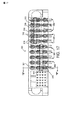
ヘッダーコネクタ300は、ハウジング301、短い電力接点302、および長い電力接点304を有する。短い電力接点302は、ハウジング301に形成された空洞306に受入れられる。長い電力接点304は、ハウジング301に形成された空洞308で受入れられる。
The
ハウジング301、短い電力接点302、および長い電力接点304は、不短い電力接点302が空洞308内に挿入されること、または、長い電力接点304が空洞306内に挿入されることを防止する分極化の特徴を有する。
特に、各空洞306、308は、そこに窓312を有する。各空洞306に関連した窓312は、図15、17および18に示されるように、空洞306の下方端に隣接して配置される。各空洞308と関連したこの窓312は、空洞306の上方端に隣接して配置される。短い、および長い電力接点302、304は、それぞれ、図16Aおよび16Bに示されるように、本体部材314a、314bを有する。短い、および長い電力接点302、304は、さらに各本体部材314a、314bの後方端縁に隣接して配置されたタブ316を有している。このタブ316は、本体部材314a、314bの主な表面にほぼ直角な方向に延びる。各短い電力接点302のタブ316は、その短い電力接点302の下方端に隣接して配置される。各長い電力接点304のタブ316は、長い電力接点304の上方端に隣接して配置される。
In particular, each cavity 306, 308 has a
タブ316は、ハウジング301の窓312内に適合するように寸法どりされる。空洞306に関連した窓312、および各短い電力端子302のタブ316は、短い電力接点302のタブ316が、それぞれ整列するように、位置決めされ、さらに、短い電力接点302が、図17に示されるように、空洞306内に挿入されるときに、空洞306の窓312の関連する1つによって受入れられる。
短い電力接点302のタブ316は、短い電力接点302のうちの1つを空洞308のうちの1つに挿入する試みがなされるときには、空洞308に関連した窓312と整列されない。むしろ、図18および19に示されるように、タブ316とハウジング301との間の干渉は、短い電力接点302が空洞308内に進むことを防止する。
The
長い電力接点304のタブ316が整列し、さらに、図17に示されるように、長い電力接点304が空洞308内に挿入されるときに、空洞308の窓312によって受入れられるように、空洞308に関連した窓312、および個々の長い電力接点304のタブ316は、同様に位置決めされる。
The
長い電力接点304のタブ316は、空洞306のうちの1つに長い電力接点304のうちの1つを挿入する試みがなされるときに、空洞306に関連した窓312とは整列しない。むしろ、図18および19に示されるように、タブ316とハウジング301との間の干渉は、長い電力接点304が空洞306内に進むのを防止する。
The
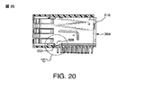
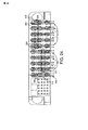
短かい、および長い電力接点302、304の本体部材314a、314bは、それぞれ図16A、16B、20、および21に示されるように、それぞれタブ328を有する。短い、および長い電力接点302、304が完全にハウジング301内に完全に挿入されるときに、タブ328は、干渉するように(interferedly)ハウジング301と係合する。タブ328とハウジング301との間の干渉は、ハウジング301内に、短い、および長い電力接点302、304を保持することを助ける。ハウジング301は、本体部材314a、314bが、ハウジング301内に挿入されるので、その最終位置にタブ328を案内するのを助ける傾斜(ramp)303を有している。
The
長い電力接点304とハウジング301のタブ316との間の上記の注記した干渉は、長い電力接点304が空洞306内に不注意で(inadvertently)搭載されるときに、長い電力接点304が干渉的にハウジング301の関連する傾斜303と係合するために、関連するタブ328用の空洞306内に十分に遠くに進むことを防止することができる。短い電力接点302とハウジングの301とのタブ316間の上記の注記した干渉は、短い電力接点302が空洞308内に不注意で搭載されるときに、同様に、短い電力接点302が、干渉的に関連する傾斜303と係合するように、関連するタブ328用の空洞308内に十分に遠くに進むことを防止することができる。
The above noted interference between the
図16Aおよび16Bに示されるように、個々の短い、および長い電力接点302、304の第2の半片314bは、2つの円筒上突出部350を有することができる。個々の短い、および長い電力接点302、304の第1の半片314aは、それぞれその突出部350のうちの1つを受入れる2つの円孔352を有することができる。短い電力接点302における突出部350と孔352との2つの組の相対的位置は、長い電力接点304における突出部350と孔352の2つの組の相対的位置と異なることができる。突出部350と孔352とは、このように、短い電力接点302の第1の半片が長い電力接点304の第2の半片と不注意に組合うことを、その逆についても、防止する分極化の特徴として作用することができる。
As shown in FIGS. 16A and 16B, the
突出部350と孔352とは、他の実施例において、円筒状および円状である以外のそれぞれの形状を有することができる。さらに、突出部350と孔352とは、それぞれ他の実施例における短い電力接点と長い電力接点302、304との第1および第2の半片323a、323bに位置することができる。
The
図22A〜24は、短い電力接点302および長い電力接点322の形状において短い、および長い電力接点302、304の他の実施例を描いている。短い、および長い電力接点320、322が、短い、および長い電力接点320、322の関連する本体部材323a、323bから外方および下方に角度を有するタブ324を有するということを除いては、短い、および長い電力接点320、322は、構造的な、かつ機能的な観点から、それぞれの、短い、および長い電力接点302、304にほぼ近似している。
FIGS. 22A-24 illustrate another embodiment of short and
付属された線図とともに読まれたときに、好ましい実施例の次の詳述と同様に、先行の要約も、一層よく理解される。この発明を例証する目的で、図面は、現在好ましい実施例を示している。しかしながら、その発明は、図面に示された特定の手段に制限されていない。図面において、
Claims (6)
前記第1の電気コネクタと組合う第2の電気コネクタであって、この第2の電気コネクタは空洞を画定する電気絶縁ハウジングであり、この第2の電気コネクタの前記ハウジングはそこに形成され前記第2の電気コネクタの周りの周囲との流体伝達内に前記第2の電気コネクタの空洞を置く孔を有するものと、前記第2の電気コネクタのハウジングの空洞内に位置された組合う部分を有する電力接点とを有し、前記第1および第2の電気コネクタが組合うときに、第1および第2の電気コネクタのハウジング内に形成された前記孔は、一部が重なり合う、コネクタ装置。 A first electrical connector, an electrically insulating housing defining a cavity, the housing having a hole formed therein for placing the cavity in fluid communication with the periphery around the first electrical connector And having a power contact having a mating portion located within the cavity;
A second electrical connector that mates with the first electrical connector, the second electrical connector being an electrically insulating housing defining a cavity, the housing of the second electrical connector being formed therein, and A hole having a cavity for the second electrical connector in fluid communication with the periphery around the second electrical connector; and a mating portion located in the cavity of the housing for the second electrical connector. A connector device, wherein the holes formed in the housings of the first and second electrical connectors partially overlap when the first and second electrical connectors are assembled.
Applications Claiming Priority (3)
| Application Number | Priority Date | Filing Date | Title |
|---|---|---|---|
| US81427506P | 2006-06-15 | 2006-06-15 | |
| US11/744,428 US7726982B2 (en) | 2006-06-15 | 2007-05-04 | Electrical connectors with air-circulation features |
| PCT/US2007/012433 WO2007145793A2 (en) | 2006-06-15 | 2007-05-26 | Electrical connectors with air-circulation and polarization features |
Publications (2)
| Publication Number | Publication Date |
|---|---|
| JP2009540527A true JP2009540527A (en) | 2009-11-19 |
| JP2009540527A5 JP2009540527A5 (en) | 2010-07-15 |
Family
ID=38832274
Family Applications (1)
| Application Number | Title | Priority Date | Filing Date |
|---|---|---|---|
| JP2009515407A Withdrawn JP2009540527A (en) | 2006-06-15 | 2007-05-26 | Electrical connector with air circulation and polarization characteristics |
Country Status (6)
| Country | Link |
|---|---|
| US (1) | US7726982B2 (en) |
| EP (2) | EP2284962A3 (en) |
| JP (1) | JP2009540527A (en) |
| KR (1) | KR20090018950A (en) |
| CN (1) | CN102157815A (en) |
| WO (1) | WO2007145793A2 (en) |
Cited By (1)
| Publication number | Priority date | Publication date | Assignee | Title |
|---|---|---|---|---|
| JP2008210805A (en) * | 2007-02-26 | 2008-09-11 | Tyco Electronics Corp | Electric connector assembly |
Families Citing this family (83)
| Publication number | Priority date | Publication date | Assignee | Title |
|---|---|---|---|---|
| US20040147169A1 (en) | 2003-01-28 | 2004-07-29 | Allison Jeffrey W. | Power connector with safety feature |
| WO2005065254A2 (en) | 2003-12-31 | 2005-07-21 | Fci Americas Technology, Inc. | Electrical power contacts and connectors comprising same |
| US7458839B2 (en) | 2006-02-21 | 2008-12-02 | Fci Americas Technology, Inc. | Electrical connectors having power contacts with alignment and/or restraining features |
| US7384289B2 (en) | 2005-01-31 | 2008-06-10 | Fci Americas Technology, Inc. | Surface-mount connector |
| US7905731B2 (en) | 2007-05-21 | 2011-03-15 | Fci Americas Technology, Inc. | Electrical connector with stress-distribution features |
| US7762857B2 (en) * | 2007-10-01 | 2010-07-27 | Fci Americas Technology, Inc. | Power connectors with contact-retention features |
| US8435047B2 (en) * | 2007-12-04 | 2013-05-07 | Molex Incorporated | Modular connectors with easy-connect capability |
| JP5125723B2 (en) * | 2008-04-22 | 2013-01-23 | 日本電気株式会社 | Connector device and electronic device |
| US8062051B2 (en) | 2008-07-29 | 2011-11-22 | Fci Americas Technology Llc | Electrical communication system having latching and strain relief features |
| US8435043B2 (en) * | 2008-08-13 | 2013-05-07 | Alltop Electronics (Suzhou) Co., Ltd | Power connector assembly |
| US7837514B2 (en) * | 2008-10-01 | 2010-11-23 | Tyco Electronics Corporation | Electrical connectors with vertically oriented contacts |
| USD606497S1 (en) | 2009-01-16 | 2009-12-22 | Fci Americas Technology, Inc. | Vertical electrical connector |
| USD664096S1 (en) | 2009-01-16 | 2012-07-24 | Fci Americas Technology Llc | Vertical electrical connector |
| USD608293S1 (en) | 2009-01-16 | 2010-01-19 | Fci Americas Technology, Inc. | Vertical electrical connector |
| USD640637S1 (en) | 2009-01-16 | 2011-06-28 | Fci Americas Technology Llc | Vertical electrical connector |
| USD610548S1 (en) | 2009-01-16 | 2010-02-23 | Fci Americas Technology, Inc. | Right-angle electrical connector |
| US8323049B2 (en) | 2009-01-30 | 2012-12-04 | Fci Americas Technology Llc | Electrical connector having power contacts |
| USD619099S1 (en) | 2009-01-30 | 2010-07-06 | Fci Americas Technology, Inc. | Electrical connector |
| US8366485B2 (en) | 2009-03-19 | 2013-02-05 | Fci Americas Technology Llc | Electrical connector having ribbed ground plate |
| USD618180S1 (en) | 2009-04-03 | 2010-06-22 | Fci Americas Technology, Inc. | Asymmetrical electrical connector |
| USD618181S1 (en) | 2009-04-03 | 2010-06-22 | Fci Americas Technology, Inc. | Asymmetrical electrical connector |
| JP5517488B2 (en) * | 2009-05-20 | 2014-06-11 | モレックス インコーポレイテド | Board to board connector |
| CN201498758U (en) * | 2009-06-26 | 2010-06-02 | 富士康(昆山)电脑接插件有限公司 | Electrical connector |
| US8616926B2 (en) * | 2009-08-17 | 2013-12-31 | Norman R. Byrne | Solid wire terminal |
| ES2606428T3 (en) * | 2009-08-26 | 2017-03-23 | Wieland Electric Gmbh | Industrial plug connector |
| US7997938B2 (en) * | 2009-10-22 | 2011-08-16 | Tyco Electronics Corporation | Electrical connector system with electrical power connection and guide features |
| CN201576796U (en) * | 2009-11-24 | 2010-09-08 | 富士康(昆山)电脑接插件有限公司 | Electric connector |
| CN102195190A (en) * | 2010-03-11 | 2011-09-21 | 凡甲电子(苏州)有限公司 | Electric connector and components thereof |
| CN102263344B (en) * | 2010-05-24 | 2013-06-05 | 凡甲电子(苏州)有限公司 | Socket power connector, plug power connector and component |
| JP5454447B2 (en) * | 2010-10-15 | 2014-03-26 | 住友電装株式会社 | connector |
| US8262395B2 (en) * | 2010-12-27 | 2012-09-11 | Chief Land Electronic Co., Ltd. | Power connector assembly with improved terminals |
| US8794991B2 (en) * | 2011-08-12 | 2014-08-05 | Fci Americas Technology Llc | Electrical connector including guidance and latch assembly |
| US8597047B2 (en) | 2011-11-14 | 2013-12-03 | Airborn, Inc. | Insulator with air dielectric cavities for electrical connector |
| JP5802561B2 (en) * | 2012-01-06 | 2015-10-28 | ホシデン株式会社 | connector |
| EP2624034A1 (en) | 2012-01-31 | 2013-08-07 | Fci | Dismountable optical coupling device |
| US9257778B2 (en) | 2012-04-13 | 2016-02-09 | Fci Americas Technology | High speed electrical connector |
| USD727268S1 (en) | 2012-04-13 | 2015-04-21 | Fci Americas Technology Llc | Vertical electrical connector |
| USD727852S1 (en) | 2012-04-13 | 2015-04-28 | Fci Americas Technology Llc | Ground shield for a right angle electrical connector |
| US8944831B2 (en) | 2012-04-13 | 2015-02-03 | Fci Americas Technology Llc | Electrical connector having ribbed ground plate with engagement members |
| USD718253S1 (en) | 2012-04-13 | 2014-11-25 | Fci Americas Technology Llc | Electrical cable connector |
| JP5632420B2 (en) * | 2012-05-07 | 2014-11-26 | ヒロセ電機株式会社 | Terminal connection structure |
| CN103390813A (en) * | 2012-05-10 | 2013-11-13 | 凡甲电子(苏州)有限公司 | Electric connector |
| US9543703B2 (en) | 2012-07-11 | 2017-01-10 | Fci Americas Technology Llc | Electrical connector with reduced stack height |
| USD751507S1 (en) | 2012-07-11 | 2016-03-15 | Fci Americas Technology Llc | Electrical connector |
| DE202012008969U1 (en) | 2012-09-18 | 2012-11-09 | Rosenberger Hochfrequenztechnik Gmbh & Co. Kg | connector |
| CN103730745B (en) * | 2012-10-16 | 2016-02-03 | 欧品电子(昆山)有限公司 | Electric connector and combination thereof |
| CN103811911B (en) * | 2012-11-08 | 2015-12-09 | 凡甲电子(苏州)有限公司 | Electric connector |
| JP5724993B2 (en) * | 2012-11-22 | 2015-05-27 | 株式会社デンソー | Connector device |
| US9093764B2 (en) | 2013-01-17 | 2015-07-28 | Cooper Technologies Company | Electrical connectors with force increase features |
| US8926360B2 (en) | 2013-01-17 | 2015-01-06 | Cooper Technologies Company | Active cooling of electrical connectors |
| CN103943994B (en) * | 2013-01-21 | 2016-02-03 | 欧品电子(昆山)有限公司 | Electric connector |
| USD745852S1 (en) | 2013-01-25 | 2015-12-22 | Fci Americas Technology Llc | Electrical connector |
| USD720698S1 (en) | 2013-03-15 | 2015-01-06 | Fci Americas Technology Llc | Electrical cable connector |
| CN104300311A (en) * | 2013-07-15 | 2015-01-21 | 凡甲电子(苏州)有限公司 | An electrical connector assembly |
| CN104425928B (en) * | 2013-08-28 | 2016-08-24 | 欧品电子(昆山)有限公司 | Electric connector |
| WO2015081064A1 (en) | 2013-11-27 | 2015-06-04 | Fci Asia Pte. Ltd | Electrical power connector |
| US20160359278A1 (en) * | 2014-02-04 | 2016-12-08 | Molex, Llc | Connector with thermal ventilation |
| TWM485540U (en) * | 2014-04-30 | 2014-09-01 | T Conn Prec Corp | Improved plug socket connector and assembly structure thereof |
| CN105449427A (en) * | 2014-09-01 | 2016-03-30 | 凡甲电子(苏州)有限公司 | Electrical connector |
| CN204167602U (en) * | 2014-09-16 | 2015-02-18 | 欧品电子(昆山)有限公司 | There is the electric connector of lead |
| CN204243228U (en) * | 2014-09-25 | 2015-04-01 | 富士康(昆山)电脑接插件有限公司 | Micro coaxial cable connector assembly |
| JP2016091598A (en) * | 2014-10-29 | 2016-05-23 | 富士通コンポーネント株式会社 | Connector and connector device |
| CN204376023U (en) * | 2015-01-29 | 2015-06-03 | 欧品电子(昆山)有限公司 | Copper bar connector and terminal assemblies |
| US9401558B1 (en) * | 2015-01-30 | 2016-07-26 | Alltop Electronics (Suzhou) Ltd. | Power connector |
| CN107431299B (en) | 2015-02-27 | 2019-05-21 | 诺曼·R·伯恩 | Electric contact receiver for busbar and blade terminal |
| CN108701922B (en) | 2015-07-07 | 2020-02-14 | Afci亚洲私人有限公司 | Electrical connector |
| CN105789950A (en) * | 2016-04-22 | 2016-07-20 | 欧品电子(昆山)有限公司 | Power connector and power terminals thereof |
| US10784631B2 (en) | 2017-01-30 | 2020-09-22 | Fci Usa Llc | Multi-piece power connector with cable pass through |
| WO2019084717A1 (en) | 2017-10-30 | 2019-05-09 | Amphenol Fci Asia Pte Ltd | Low crosstalk card edge connector |
| WO2020073460A1 (en) | 2018-10-09 | 2020-04-16 | Amphenol Commercial Products (Chengdu) Co. Ltd. | High-density edge connector |
| TWM576774U (en) | 2018-11-15 | 2019-04-11 | 香港商安費諾(東亞)有限公司 | Metal case with anti-displacement structure and connector thereof |
| CN110011092B (en) * | 2019-03-22 | 2021-08-20 | 富士康(昆山)电脑接插件有限公司 | Electrical connector |
| TWM582251U (en) | 2019-04-22 | 2019-08-11 | 香港商安費諾(東亞)有限公司 | Connector set with hidden locking mechanism and socket connector thereof |
| DE102019111749A1 (en) | 2019-05-07 | 2020-11-12 | Te Connectivity Germany Gmbh | Electrical connector and electrical plug connection |
| USD1016752S1 (en) * | 2019-06-19 | 2024-03-05 | Tyco Electronics (Shanghai) Co., Ltd. | Electrical connector |
| US11588277B2 (en) | 2019-11-06 | 2023-02-21 | Amphenol East Asia Ltd. | High-frequency electrical connector with lossy member |
| US11799230B2 (en) | 2019-11-06 | 2023-10-24 | Amphenol East Asia Ltd. | High-frequency electrical connector with in interlocking segments |
| CN110829095A (en) * | 2019-11-09 | 2020-02-21 | 富士康(昆山)电脑接插件有限公司 | Electrical connector |
| CN113540856B (en) * | 2020-04-20 | 2023-08-25 | 泰科电子(上海)有限公司 | Connector with a plurality of connectors |
| US11539154B2 (en) * | 2020-07-21 | 2022-12-27 | Te Connectivity Solutions Gmbh | Power contact for electrical connector |
| US11652307B2 (en) | 2020-08-20 | 2023-05-16 | Amphenol East Asia Electronic Technology (Shenzhen) Co., Ltd. | High speed connector |
| CN212874843U (en) | 2020-08-31 | 2021-04-02 | 安费诺商用电子产品(成都)有限公司 | Electrical connector |
| WO2024033920A1 (en) | 2022-08-09 | 2024-02-15 | Kramer Electronics Ltd. | Enhanced heat exchange mechanism for wall plate devices |
Family Cites Families (317)
| Publication number | Priority date | Publication date | Assignee | Title |
|---|---|---|---|---|
| US622896A (en) * | 1899-04-11 | Bucket-chain for water elevators and purifiers | ||
| US318186A (en) * | 1885-05-19 | Electric railway-signal | ||
| US741052A (en) | 1902-01-04 | 1903-10-13 | Minna Legare Mahon | Automatic coupling for electrical conductors. |
| CH104663A (en) | 1923-04-03 | 1924-05-01 | Raettig Bruno | Contact spring. |
| US2248675A (en) | 1939-10-24 | 1941-07-08 | Huppert William | Multiple finger electrical contact and method of making the same |
| US2430011A (en) | 1944-05-15 | 1947-11-04 | Lunceford P Gillentine | Plug ejector |
| US2759163A (en) | 1951-09-13 | 1956-08-14 | Continental Copper & Steel Ind | Electrical connection |
| US2762022A (en) | 1954-08-30 | 1956-09-04 | Gen Electric | Wire terminal connector |
| US2844644A (en) | 1956-12-20 | 1958-07-22 | Gen Electric | Detachable spring contact device |
| US3011143A (en) | 1959-02-10 | 1961-11-28 | Cannon Electric Co | Electrical connector |
| US3208030A (en) | 1962-12-06 | 1965-09-21 | Ibm | Electrical connector |
| US3420087A (en) * | 1963-02-18 | 1969-01-07 | Amp Inc | Electrical connector means and method of manufacture |
| US3411127A (en) | 1963-07-08 | 1968-11-12 | Gen Electric | Self-mating electric connector assembly |
| US3286220A (en) | 1964-06-10 | 1966-11-15 | Amp Inc | Electrical connector means |
| US3178669A (en) * | 1964-06-12 | 1965-04-13 | Amp Inc | Electrical connecting device |
| DE1615001B2 (en) | 1965-09-11 | 1971-07-08 | Wago Kontakttechnik GmbH 4950 Minden | ELECTRIC CONNECTOR |
| US3538486A (en) | 1967-05-25 | 1970-11-03 | Amp Inc | Connector device with clamping contact means |
| DE1665181B1 (en) | 1967-12-23 | 1974-04-11 | Multi Contact Ag | Electric clutch |
| US3514740A (en) * | 1968-03-04 | 1970-05-26 | John Richard Filson | Wire-end connector structure |
| GB1226935A (en) * | 1968-09-23 | 1971-03-31 | ||
| US3871015A (en) * | 1969-08-14 | 1975-03-11 | Ibm | Flip chip module with non-uniform connector joints |
| US3669054A (en) | 1970-03-23 | 1972-06-13 | Amp Inc | Method of manufacturing electrical terminals |
| US3692994A (en) | 1971-04-14 | 1972-09-19 | Pitney Bowes Sage Inc | Flash tube holder assembly |
| US3748633A (en) | 1972-01-24 | 1973-07-24 | Amp Inc | Square post connector |
| US3845451A (en) | 1973-02-26 | 1974-10-29 | Multi Contact Ag | Electrical coupling arrangement |
| GB1490195A (en) | 1973-12-28 | 1977-10-26 | Rists Wires & Cables Ltd | Electrical terminals |
| US3942856A (en) * | 1974-12-23 | 1976-03-09 | Mindheim Daniel J | Safety socket assembly |
| US4070088A (en) * | 1975-08-05 | 1978-01-24 | Microdot, Inc. | Contact construction |
| US4076362A (en) * | 1976-02-20 | 1978-02-28 | Japan Aviation Electronics Industry Ltd. | Contact driver |
| US4152700A (en) * | 1976-03-01 | 1979-05-01 | Westinghouse Electric Corp. | Radar extractor having means for estimating target location with a range cell |
| US4082407A (en) * | 1977-05-20 | 1978-04-04 | Amerace Corporation | Terminal block with encapsulated heat sink |
| US4136919A (en) * | 1977-11-04 | 1979-01-30 | Howard Guy W | Electrical receptacle with releasable locking means |
| US4217024A (en) | 1977-11-07 | 1980-08-12 | Burroughs Corporation | Dip socket having preloading and antiwicking features |
| US4159861A (en) | 1977-12-30 | 1979-07-03 | International Telephone And Telegraph Corporation | Zero insertion force connector |
| US4473113A (en) | 1978-04-14 | 1984-09-25 | Whitfield Fred J | Methods and materials for conducting heat from electronic components and the like |
| US4403821A (en) | 1979-03-05 | 1983-09-13 | Amp Incorporated | Wiring line tap |
| US4288139A (en) | 1979-03-06 | 1981-09-08 | Amp Incorporated | Trifurcated card edge terminal |
| US4260212A (en) * | 1979-03-20 | 1981-04-07 | Amp Incorporated | Method of producing insulated terminals |
| NL8003228A (en) * | 1980-06-03 | 1982-01-04 | Du Pont Nederland | BRIDGE CONTACT FOR THE ELECTRICAL CONNECTION OF TWO PINS. |
| US4371912A (en) | 1980-10-01 | 1983-02-01 | Motorola, Inc. | Method of mounting interrelated components |
| US4402563A (en) | 1981-05-26 | 1983-09-06 | Aries Electronics, Inc. | Zero insertion force connector |
| ZA826825B (en) | 1981-10-02 | 1983-07-27 | Int Computers Ltd | Devices for mounting integrated circuit packages on a printed circuit board |
| US4533187A (en) | 1983-01-06 | 1985-08-06 | Augat Inc. | Dual beam connector |
| US4552425A (en) | 1983-07-27 | 1985-11-12 | Amp Incorporated | High current connector |
| US4505529A (en) | 1983-11-01 | 1985-03-19 | Amp Incorporated | Electrical connector for use between circuit boards |
| US4545610A (en) | 1983-11-25 | 1985-10-08 | International Business Machines Corporation | Method for forming elongated solder connections between a semiconductor device and a supporting substrate |
| FR2559624B1 (en) * | 1984-02-14 | 1986-05-23 | Labinal | ELECTRIC CONTACT MEMBER |
| US4560222A (en) | 1984-05-17 | 1985-12-24 | Molex Incorporated | Drawer connector |
| US4596433A (en) | 1984-12-13 | 1986-06-24 | North American Philips Corporation | Lampholder having internal cooling passages |
| US4717360A (en) * | 1986-03-17 | 1988-01-05 | Zenith Electronics Corporation | Modular electrical connector |
| US4790763A (en) | 1986-04-22 | 1988-12-13 | Amp Incorporated | Programmable modular connector assembly |
| US4820169A (en) * | 1986-04-22 | 1989-04-11 | Amp Incorporated | Programmable modular connector assembly |
| US4881905A (en) | 1986-05-23 | 1989-11-21 | Amp Incorporated | High density controlled impedance connector |
| US4878611A (en) | 1986-05-30 | 1989-11-07 | American Telephone And Telegraph Company, At&T Bell Laboratories | Process for controlling solder joint geometry when surface mounting a leadless integrated circuit package on a substrate |
| US4685886A (en) | 1986-06-27 | 1987-08-11 | Amp Incorporated | Electrical plug header |
| US4767344A (en) | 1986-08-22 | 1988-08-30 | Burndy Corporation | Solder mounting of electrical contacts |
| US4782893A (en) | 1986-09-15 | 1988-11-08 | Trique Concepts, Inc. | Electrically insulating thermally conductive pad for mounting electronic components |
| US4776803A (en) | 1986-11-26 | 1988-10-11 | Minnesota Mining And Manufacturing Company | Integrally molded card edge cable termination assembly, contact, machine and method |
| CA1285036C (en) | 1986-12-26 | 1991-06-18 | Kyoichiro Kawano | Electrical connector |
| KR910001862B1 (en) | 1987-02-24 | 1991-03-28 | 가부시끼가이샤 도시바 | Contact of connector |
| US4818237A (en) * | 1987-09-04 | 1989-04-04 | Amp Incorporated | Modular plug-in connection means for flexible power supply of electronic apparatus |
| US4820182A (en) * | 1987-12-18 | 1989-04-11 | Molex Incorporated | Hermaphroditic L. I. F. mating electrical contacts |
| US4915641A (en) * | 1988-08-31 | 1990-04-10 | Molex Incorporated | Modular drawer connector |
| US4974119A (en) | 1988-09-14 | 1990-11-27 | The Charles Stark Draper Laboratories, Inc. | Conforming heat sink assembly |
| US4907990A (en) * | 1988-10-07 | 1990-03-13 | Molex Incorporated | Elastically supported dual cantilever beam pin-receiving electrical contact |
| US4975084A (en) | 1988-10-17 | 1990-12-04 | Amp Incorporated | Electrical connector system |
| JPH02199780A (en) | 1989-01-30 | 1990-08-08 | Yazaki Corp | Low inserting force terminal |
| US4900271A (en) * | 1989-02-24 | 1990-02-13 | Molex Incorporated | Electrical connector for fuel injector and terminals therefor |
| US4965699A (en) | 1989-04-18 | 1990-10-23 | Magnavox Government And Industrial Electronics Company | Circuit card assembly cold plate |
| US4979074A (en) | 1989-06-12 | 1990-12-18 | Flavors Technology | Printed circuit board heat sink |
| US5024610A (en) | 1989-08-16 | 1991-06-18 | Amp Incorporated | Low profile spring contact with protective guard means |
| US5077893A (en) * | 1989-09-26 | 1992-01-07 | Molex Incorporated | Method for forming electrical terminal |
| US5016968A (en) * | 1989-09-27 | 1991-05-21 | At&T Bell Laboratories | Duplex optical fiber connector and cables terminated therewith |
| DE69018000T2 (en) | 1989-10-10 | 1995-09-28 | Whitaker Corp | Backplane connector with matched impedance. |
| US5052953A (en) | 1989-12-15 | 1991-10-01 | Amp Incorporated | Stackable connector assembly |
| AU645283B2 (en) * | 1990-01-23 | 1994-01-13 | Sumitomo Electric Industries, Ltd. | Substrate for packaging a semiconductor device |
| US4963102A (en) | 1990-01-30 | 1990-10-16 | Gettig Technologies | Electrical connector of the hermaphroditic type |
| US4973257A (en) | 1990-02-13 | 1990-11-27 | The Chamberlain Group, Inc. | Battery terminal |
| US5035639A (en) | 1990-03-20 | 1991-07-30 | Amp Incorporated | Hermaphroditic electrical connector |
| US5082459A (en) * | 1990-08-23 | 1992-01-21 | Amp Incorporated | Dual readout simm socket |
| JP2739608B2 (en) | 1990-11-15 | 1998-04-15 | 日本エー・エム・ピー株式会社 | Multi-contact type connector for signal transmission |
| US5046960A (en) | 1990-12-20 | 1991-09-10 | Amp Incorporated | High density connector system |
| US5104332A (en) * | 1991-01-22 | 1992-04-14 | Group Dekko International | Modular furniture power distribution system and electrical connector therefor |
| US5151056A (en) | 1991-03-29 | 1992-09-29 | Elco Corporation | Electrical contact system with cantilever mating beams |
| US5094634A (en) * | 1991-04-11 | 1992-03-10 | Molex Incorporated | Electrical connector employing terminal pins |
| US5194480A (en) | 1991-05-24 | 1993-03-16 | W. R. Grace & Co.-Conn. | Thermally conductive elastomer |
| US5137959A (en) | 1991-05-24 | 1992-08-11 | W. R. Grace & Co.-Conn. | Thermally conductive elastomer containing alumina platelets |
| US5152700A (en) | 1991-06-17 | 1992-10-06 | Litton Systems, Inc. | Printed circuit board connector system |
| JP2583839B2 (en) | 1991-07-24 | 1997-02-19 | ヒロセ電機株式会社 | High speed transmission electrical connector |
| US5213868A (en) * | 1991-08-13 | 1993-05-25 | Chomerics, Inc. | Thermally conductive interface materials and methods of using the same |
| FI109960B (en) | 1991-09-19 | 2002-10-31 | Nokia Corp | Electronic device |
| US5139426A (en) | 1991-12-11 | 1992-08-18 | Amp Incorporated | Adjunct power connector |
| NL9200118A (en) | 1992-01-22 | 1993-08-16 | Du Pont Nederland | ELECTRICAL CONNECTOR WITH PLATE MATERIAL CONNECTORS. |
| GB9205087D0 (en) * | 1992-03-09 | 1992-04-22 | Amp Holland | Sheilded back plane connector |
| US5205738A (en) * | 1992-04-03 | 1993-04-27 | International Business Machines Corporation | High density connector system |
| US5521519A (en) * | 1992-07-30 | 1996-05-28 | International Business Machines Corporation | Spring probe with piloted and headed contact and method of tip formation |
| US5254012A (en) | 1992-08-21 | 1993-10-19 | Industrial Technology Research Institute | Zero insertion force socket |
| JP3161642B2 (en) | 1992-12-18 | 2001-04-25 | 富士通株式会社 | Connector and method of assembling the same |
| US5295843A (en) | 1993-01-19 | 1994-03-22 | The Whitaker Corporation | Electrical connector for power and signal contacts |
| US5302135A (en) * | 1993-02-09 | 1994-04-12 | Lee Feng Jui | Electrical plug |
| US5274918A (en) * | 1993-04-15 | 1994-01-04 | The Whitaker Corporation | Method for producing contact shorting bar insert for modular jack assembly |
| US5321582A (en) | 1993-04-26 | 1994-06-14 | Cummins Engine Company, Inc. | Electronic component heat sink attachment using a low force spring |
| JPH0680270U (en) | 1993-04-26 | 1994-11-08 | 住友電装株式会社 | connector |
| US5810607A (en) | 1995-09-13 | 1998-09-22 | International Business Machines Corporation | Interconnector with contact pads having enhanced durability |
| US5381314A (en) * | 1993-06-11 | 1995-01-10 | The Whitaker Corporation | Heat dissipating EMI/RFI protective function box |
| FR2710463B1 (en) | 1993-09-20 | 1995-11-10 | Alcatel Cable Interface | Hermaphroditic contact and connection defined by a pair of such contacts. |
| US5533915A (en) | 1993-09-23 | 1996-07-09 | Deans; William S. | Electrical connector assembly |
| US5772451A (en) | 1993-11-16 | 1998-06-30 | Form Factor, Inc. | Sockets for electronic components and methods of connecting to electronic components |
| US5742848A (en) * | 1993-11-16 | 1998-04-21 | Microsoft Corp. | System for passing messages between source object and target object utilizing generic code in source object to invoke any member function of target object by executing the same instructions |
| US5490040A (en) * | 1993-12-22 | 1996-02-06 | International Business Machines Corporation | Surface mount chip package having an array of solder ball contacts arranged in a circle and conductive pin contacts arranged outside the circular array |
| KR970009863B1 (en) | 1994-01-22 | 1997-06-18 | 금성일렉트론 주식회사 | Forming method of insulated film in the semiconductor device |
| EP0745279B1 (en) * | 1994-02-15 | 2002-05-22 | Berg Electronics Manufacturing B.V. | Shielded circuit board connector module |
| US5431578A (en) | 1994-03-02 | 1995-07-11 | Abrams Electronics, Inc. | Compression mating electrical connector |
| US5457342A (en) | 1994-03-30 | 1995-10-10 | Herbst, Ii; Gerhardt G. | Integrated circuit cooling apparatus |
| US5427543A (en) | 1994-05-02 | 1995-06-27 | Dynia; Gregory G. | Electrical connector prong lock |
| FR2719706B1 (en) | 1994-05-03 | 1996-05-31 | Cinch Connecteurs Sa | Hermaphroditic electrical contact member. |
| US5615824A (en) | 1994-06-07 | 1997-04-01 | Tessera, Inc. | Soldering with resilient contacts |
| US5618187A (en) * | 1994-11-17 | 1997-04-08 | The Whitaker Corporation | Board mount bus bar contact |
| US5582519A (en) | 1994-12-15 | 1996-12-10 | The Whitaker Corporation | Make-first-break-last ground connections |
| US5564952A (en) | 1994-12-22 | 1996-10-15 | The Whitaker Corporation | Electrical plug connector with blade receiving slots |
| US5664973A (en) | 1995-01-05 | 1997-09-09 | Motorola, Inc. | Conductive contact |
| US5584709A (en) | 1995-01-30 | 1996-12-17 | Molex Incorporated | Printed circuit board mounted electrical connector |
| US5637008A (en) | 1995-02-01 | 1997-06-10 | Methode Electronics, Inc. | Zero insertion force miniature grid array socket |
| US5667392A (en) | 1995-03-28 | 1997-09-16 | The Whitaker Corporation | Electrical connector with stabilized contact |
| US5609502A (en) * | 1995-03-31 | 1997-03-11 | The Whitaker Corporation | Contact retention system |
| US5743009A (en) * | 1995-04-07 | 1998-04-28 | Hitachi, Ltd. | Method of making multi-pin connector |
| US5580257A (en) * | 1995-04-28 | 1996-12-03 | Molex Incorporated | High performance card edge connector |
| US5817973A (en) | 1995-06-12 | 1998-10-06 | Berg Technology, Inc. | Low cross talk and impedance controlled electrical cable assembly |
| TW267265B (en) | 1995-06-12 | 1996-01-01 | Connector Systems Tech Nv | Low cross talk and impedance controlled electrical connector |
| US5590463A (en) * | 1995-07-18 | 1997-01-07 | Elco Corporation | Circuit board connectors |
| JP3616167B2 (en) | 1995-08-10 | 2005-02-02 | 株式会社相川プレス工業 | High current board connector |
| US5558542A (en) | 1995-09-08 | 1996-09-24 | Molex Incorporated | Electrical connector with improved terminal-receiving passage means |
| US5749746A (en) * | 1995-09-26 | 1998-05-12 | Hon Hai Precision Ind. Co., Ltd. | Cable connector structure |
| US5971817A (en) | 1995-09-27 | 1999-10-26 | Siemens Aktiengesellschaft | Contact spring for a plug-in connector |
| US5691041A (en) | 1995-09-29 | 1997-11-25 | International Business Machines Corporation | Socket for semi-permanently connecting a solder ball grid array device using a dendrite interposer |
| US5702255A (en) | 1995-11-03 | 1997-12-30 | Advanced Interconnections Corporation | Ball grid array socket assembly |
| US5746608A (en) | 1995-11-30 | 1998-05-05 | Taylor; Attalee S. | Surface mount socket for an electronic package, and contact for use therewith |
| US5741161A (en) * | 1996-01-04 | 1998-04-21 | Pcd Inc. | Electrical connection system with discrete wire interconnections |
| SG77096A1 (en) | 1996-02-06 | 2000-12-19 | Molex Inc | Anti-wicking system for electrical connectors |
| US5643009A (en) | 1996-02-26 | 1997-07-01 | The Whitaker Corporation | Electrical connector having a pivot lock |
| US5787971A (en) | 1996-03-25 | 1998-08-04 | Dodson; Douglas A. | Multiple fan cooling device |
| US5664968A (en) | 1996-03-29 | 1997-09-09 | The Whitaker Corporation | Connector assembly with shielded modules |
| US5831314A (en) | 1996-04-09 | 1998-11-03 | United Microelectronics Corporation | Trench-shaped read-only memory and its method of fabrication |
| CN1216638A (en) * | 1996-04-22 | 1999-05-12 | 西门子公司 | Plug-in connector with contact surface protection in the plug-in opening area |
| US5727963A (en) * | 1996-05-01 | 1998-03-17 | Lemaster; Dolan M. | Modular power connector assembly |
| JP3315313B2 (en) * | 1996-05-17 | 2002-08-19 | 矢崎総業株式会社 | Connector structure |
| US5984726A (en) | 1996-06-07 | 1999-11-16 | Hon Hai Precision Ind. Co., Ltd. | Shielded electrical connector |
| US6056590A (en) | 1996-06-25 | 2000-05-02 | Fujitsu Takamisawa Component Limited | Connector having internal switch and fabrication method thereof |
| US5755595A (en) * | 1996-06-27 | 1998-05-26 | Whitaker Corporation | Shielded electrical connector |
| US5882214A (en) * | 1996-06-28 | 1999-03-16 | The Whitaker Corporation | Electrical connector with contact assembly |
| TW354200U (en) * | 1996-07-18 | 1999-03-01 | Hon Hai Prec Ind Co Ltd | Fastener for connector |
| US5795191A (en) | 1996-09-11 | 1998-08-18 | Preputnick; George | Connector assembly with shielded modules and method of making same |
| US5833421A (en) | 1996-09-16 | 1998-11-10 | Alpine Engineered Products, Inc. | Connector plate |
| US6095827A (en) | 1996-10-24 | 2000-08-01 | Berg Technology, Inc. | Electrical connector with stress isolating solder tail |
| US6139336A (en) | 1996-11-14 | 2000-10-31 | Berg Technology, Inc. | High density connector having a ball type of contact surface |
| US6810783B1 (en) | 1996-11-18 | 2004-11-02 | Larose Claude | Saw tooth |
| DE29621604U1 (en) | 1996-12-12 | 1998-01-02 | Cooper Tools Gmbh | Soldering / desoldering device |
| JP3509444B2 (en) * | 1997-01-13 | 2004-03-22 | 住友電装株式会社 | Insert molding connector |
| US5876248A (en) * | 1997-01-14 | 1999-03-02 | Molex Incorporated | Matable electrical connectors having signal and power terminals |
| US6183301B1 (en) * | 1997-01-16 | 2001-02-06 | Berg Technology, Inc. | Surface mount connector with integrated PCB assembly |
| US5980321A (en) | 1997-02-07 | 1999-11-09 | Teradyne, Inc. | High speed, high density electrical connector |
| US5993259A (en) | 1997-02-07 | 1999-11-30 | Teradyne, Inc. | High speed, high density electrical connector |
| US5742484A (en) | 1997-02-18 | 1998-04-21 | Motorola, Inc. | Flexible connector for circuit boards |
| US6180891B1 (en) | 1997-02-26 | 2001-01-30 | International Business Machines Corporation | Control of size and heat affected zone for fine pitch wire bonding |
| US5883782A (en) | 1997-03-05 | 1999-03-16 | Intel Corporation | Apparatus for attaching a heat sink to a PCB mounted semiconductor package |
| US6068520A (en) | 1997-03-13 | 2000-05-30 | Berg Technology, Inc. | Low profile double deck connector with improved cross talk isolation |
| US5919050A (en) | 1997-04-14 | 1999-07-06 | International Business Machines Corporation | Method and apparatus for separable interconnecting electronic components |
| US5874776A (en) * | 1997-04-21 | 1999-02-23 | International Business Machines Corporation | Thermal stress relieving substrate |
| TW321372U (en) * | 1997-05-16 | 1997-11-21 | Molex Taiwan Co Ltd | Electrical connector to block the EMI (Electromagnetic Interference) |
| JP3379747B2 (en) * | 1997-05-20 | 2003-02-24 | 矢崎総業株式会社 | Low insertion force terminal |
| US6146157A (en) | 1997-07-08 | 2000-11-14 | Framatome Connectors International | Connector assembly for printed circuit boards |
| US5908333A (en) | 1997-07-21 | 1999-06-01 | Rambus, Inc. | Connector with integral transmission line bus |
| US5876219A (en) | 1997-08-29 | 1999-03-02 | The Whitaker Corp. | Board-to-board connector assembly |
| US5955888A (en) | 1997-09-10 | 1999-09-21 | Xilinx, Inc. | Apparatus and method for testing ball grid array packaged integrated circuits |
| JP3269436B2 (en) | 1997-09-19 | 2002-03-25 | 株式会社村田製作所 | Manufacturing method of insert resin molded product |
| US5975921A (en) | 1997-10-10 | 1999-11-02 | Berg Technology, Inc. | High density connector system |
| US5930114A (en) | 1997-10-23 | 1999-07-27 | Thermalloy Incorporated | Heat sink mounting assembly for surface mount electronic device packages |
| TW361737U (en) | 1997-11-24 | 1999-06-11 | Hon Hai Prec Ind Co Ltd | Power connector assembly |
| US5961355A (en) | 1997-12-17 | 1999-10-05 | Berg Technology, Inc. | High density interstitial connector system |
| US5888884A (en) * | 1998-01-02 | 1999-03-30 | General Electric Company | Electronic device pad relocation, precision placement, and packaging in arrays |
| DE19829467C2 (en) * | 1998-07-01 | 2003-06-18 | Amphenol Tuchel Elect | Contact carrier especially for a thin smart card connector |
| US6200143B1 (en) | 1998-01-09 | 2001-03-13 | Tessera, Inc. | Low insertion force connector for microelectronic elements |
| GB9804333D0 (en) | 1998-02-27 | 1998-04-22 | Amp Great Britain | Device-to-board electrical connector |
| US6319075B1 (en) * | 1998-04-17 | 2001-11-20 | Fci Americas Technology, Inc. | Power connector |
| US20020098743A1 (en) | 1998-04-17 | 2002-07-25 | Schell Mark S. | Power connector |
| US6071152A (en) | 1998-04-22 | 2000-06-06 | Molex Incorporated | Electrical connector with inserted terminals |
| JP2000003746A (en) | 1998-06-15 | 2000-01-07 | Honda Tsushin Kogyo Co Ltd | Connector for printed circuit board |
| JP3755989B2 (en) | 1998-06-15 | 2006-03-15 | 本多通信工業株式会社 | PCB connector |
| JP2000003744A (en) | 1998-06-15 | 2000-01-07 | Honda Tsushin Kogyo Co Ltd | Connector for printed circuit board |
| JP2000003745A (en) | 1998-06-15 | 2000-01-07 | Honda Tsushin Kogyo Co Ltd | Connector for printed circuit board |
| US6059170A (en) * | 1998-06-24 | 2000-05-09 | International Business Machines Corporation | Method and apparatus for insulating moisture sensitive PBGA's |
| US6146202A (en) | 1998-08-12 | 2000-11-14 | Robinson Nugent, Inc. | Connector apparatus |
| US6299492B1 (en) | 1998-08-20 | 2001-10-09 | A. W. Industries, Incorporated | Electrical connectors |
| US6402566B1 (en) | 1998-09-15 | 2002-06-11 | Tvm Group, Inc. | Low profile connector assembly and pin and socket connectors for use therewith |
| US6238225B1 (en) | 1998-09-23 | 2001-05-29 | Tvm Group, Inc. | Bus bar assembly |
| AUPP712998A0 (en) | 1998-11-16 | 1998-12-10 | Field, Christopher David | Noise attenuation device |
| US6685886B2 (en) | 1998-12-17 | 2004-02-03 | Genencor International, Inc. | Agitation system for a fluid bed processing system and a method thereof |
| TW393812B (en) * | 1998-12-24 | 2000-06-11 | Hon Hai Prec Ind Co Ltd | A manufacturing method of high-density electrical connector and its product |
| US6259039B1 (en) | 1998-12-29 | 2001-07-10 | Intel Corporation | Surface mount connector with pins in vias |
| TW445679B (en) | 1998-12-31 | 2001-07-11 | Hon Hai Prec Ind Co Ltd | Method for manufacturing modular terminals of electrical connector |
| US6183287B1 (en) * | 1998-12-31 | 2001-02-06 | Hon Hai Precision Ind. Co., Ltd. | Electrical connector |
| TW465146B (en) * | 1999-02-02 | 2001-11-21 | Hon Hai Prec Ind Co Ltd | Thermal expansion adjustment method of plate-shaped electronic devices and the structure thereof |
| JP4187338B2 (en) | 1999-03-01 | 2008-11-26 | モレックス インコーポレーテッド | Electrical connector |
| US6215180B1 (en) * | 1999-03-17 | 2001-04-10 | First International Computer Inc. | Dual-sided heat dissipating structure for integrated circuit package |
| TW433624U (en) | 1999-04-06 | 2001-05-01 | Hon Hai Prec Ind Co Ltd | Electrical connector |
| TW438127U (en) * | 1999-04-16 | 2001-05-28 | Hon Hai Prec Ind Co Ltd | Electrical connector |
| US6174198B1 (en) * | 1999-04-21 | 2001-01-16 | Hon Hai Precision Ind. Co., Ltd. | Electrical connector assembly |
| US6362961B1 (en) * | 1999-04-22 | 2002-03-26 | Ming Chin Chiou | CPU and heat sink mounting arrangement |
| US6281438B1 (en) * | 1999-05-05 | 2001-08-28 | Leviton Manufacturing Co., Inc. | Flush mount power receptacle with integral wall plate |
| US6220896B1 (en) | 1999-05-13 | 2001-04-24 | Berg Technology, Inc. | Shielded header |
| TW592400U (en) * | 1999-05-15 | 2004-06-11 | Hon Hai Prec Ind Co Ltd | Electrical connector |
| US6193537B1 (en) * | 1999-05-24 | 2001-02-27 | Berg Technology, Inc. | Hermaphroditic contact |
| US6123554A (en) | 1999-05-28 | 2000-09-26 | Berg Technology, Inc. | Connector cover with board stiffener |
| US6202916B1 (en) * | 1999-06-08 | 2001-03-20 | Delphi Technologies, Inc. | Method of wave soldering thin laminate circuit boards |
| JP3397303B2 (en) | 1999-06-17 | 2003-04-14 | エヌイーシートーキン株式会社 | Connector and manufacturing method thereof |
| US6139363A (en) * | 1999-07-09 | 2000-10-31 | Hon Hai Precision Ind. Co., Ltd. | Micro connector assembly and method of making the same |
| JP2001102131A (en) | 1999-10-01 | 2001-04-13 | Sumitomo Wiring Syst Ltd | Connector |
| JP3473521B2 (en) | 1999-10-08 | 2003-12-08 | 住友電装株式会社 | Female terminal fitting |
| JP2001118629A (en) | 1999-10-18 | 2001-04-27 | Jst Mfg Co Ltd | Cooling method of connector and electronic module mounted on the connector |
| JP4184660B2 (en) | 1999-10-18 | 2008-11-19 | エルニ エレクトロニクス ゲーエムベーハー | Plug-in connection device having a shielding part |
| TW484251B (en) * | 1999-10-19 | 2002-04-21 | Berg Tech Inc | Electrical connector with strain relief |
| US6274474B1 (en) | 1999-10-25 | 2001-08-14 | International Business Machines Corporation | Method of forming BGA interconnections having mixed solder profiles |
| US6234851B1 (en) | 1999-11-09 | 2001-05-22 | General Electric Company | Stab connector assembly |
| SG101926A1 (en) | 1999-11-12 | 2004-02-27 | Molex Inc | Power connector |
| EP1427061B1 (en) | 1999-11-24 | 2011-04-20 | Amphenol Corporation | Differential signal electrical connectors |
| JP2001167839A (en) | 1999-12-01 | 2001-06-22 | Molex Inc | Electrical connector assembly |
| US6359783B1 (en) * | 1999-12-29 | 2002-03-19 | Intel Corporation | Integrated circuit socket having a built-in voltage regulator |
| DE10001184B4 (en) | 2000-01-14 | 2007-06-06 | Rittal Gmbh & Co. Kg | Device for connecting busbars of a busbar system with the terminals of an electrical installation device |
| US6293827B1 (en) | 2000-02-03 | 2001-09-25 | Teradyne, Inc. | Differential signal electrical connector |
| US6384142B1 (en) | 2000-02-08 | 2002-05-07 | Exxonmobil Chemical Patents Inc. | Propylene impact copolymers |
| US6471523B1 (en) | 2000-02-23 | 2002-10-29 | Berg Technology, Inc. | Electrical power connector |
| US6371773B1 (en) * | 2000-03-23 | 2002-04-16 | Ohio Associated Enterprises, Inc. | High density interconnect system and method |
| US6386924B2 (en) | 2000-03-31 | 2002-05-14 | Tyco Electronics Corporation | Connector assembly with stabilized modules |
| JP2001319718A (en) * | 2000-05-02 | 2001-11-16 | Fci Japan Kk | Connector |
| DE10027125A1 (en) | 2000-05-31 | 2001-12-06 | Wabco Gmbh & Co Ohg | Electrical plug contact |
| DE10027556C1 (en) * | 2000-06-02 | 2001-11-29 | Harting Kgaa | PCB connector |
| JP3724345B2 (en) | 2000-07-13 | 2005-12-07 | 日産自動車株式会社 | Wiring connection structure |
| US6350134B1 (en) * | 2000-07-25 | 2002-02-26 | Tyco Electronics Corporation | Electrical connector having triad contact groups arranged in an alternating inverted sequence |
| US6210240B1 (en) * | 2000-07-28 | 2001-04-03 | Molex Incorporated | Electrical connector with improved terminal |
| US6851869B2 (en) | 2000-08-04 | 2005-02-08 | Cool Options, Inc. | Highly thermally conductive electronic connector |
| US6360940B1 (en) | 2000-11-08 | 2002-03-26 | International Business Machines Corporation | Method and apparatus for removing known good die |
| US6309245B1 (en) | 2000-12-18 | 2001-10-30 | Powerwave Technologies, Inc. | RF amplifier assembly with reliable RF pallet ground |
| US6261132B1 (en) | 2000-12-29 | 2001-07-17 | Hon Hai Precision Ind. Co., Ltd. | Header connector for future bus |
| US6592381B2 (en) | 2001-01-25 | 2003-07-15 | Teradyne, Inc. | Waferized power connector |
| US6409543B1 (en) | 2001-01-25 | 2002-06-25 | Teradyne, Inc. | Connector molding method and shielded waferized connector made therefrom |
| DE60227915D1 (en) | 2001-01-29 | 2008-09-11 | Tyco Electronics Corp | HIGH DENSITY CONNECTOR SOCKET |
| US6461202B2 (en) | 2001-01-30 | 2002-10-08 | Tyco Electronics Corporation | Terminal module having open side for enhanced electrical performance |
| CA2437371A1 (en) * | 2001-02-01 | 2002-08-08 | Teradyne, Inc. | Matrix connector |
| DE10105042C1 (en) | 2001-02-05 | 2002-08-22 | Harting Kgaa | Contact module for a connector, especially for a card edge connector |
| US6947012B2 (en) | 2001-02-15 | 2005-09-20 | Integral Technologies, Inc. | Low cost electrical cable connector housings and cable heads manufactured from conductive loaded resin-based materials |
| US6394818B1 (en) | 2001-03-27 | 2002-05-28 | Hon Hai Precision Ind. Co., Ltd. | Power connector |
| JP2002298938A (en) | 2001-03-30 | 2002-10-11 | Jst Mfg Co Ltd | Electrical connector for twisted pair cable using resin solder, and method of connecting electric wire to the electrical connector |
| US6686664B2 (en) | 2001-04-30 | 2004-02-03 | International Business Machines Corporation | Structure to accommodate increase in volume expansion during solder reflow |
| US6506081B2 (en) | 2001-05-31 | 2003-01-14 | Tyco Electronics Corporation | Floatable connector assembly with a staggered overlapping contact pattern |
| US6431914B1 (en) | 2001-06-04 | 2002-08-13 | Hon Hai Precision Ind. Co., Ltd. | Grounding scheme for a high speed backplane connector system |
| US6488549B1 (en) | 2001-06-06 | 2002-12-03 | Tyco Electronics Corporation | Electrical connector assembly with separate arcing zones |
| US6776635B2 (en) | 2001-06-14 | 2004-08-17 | Tyco Electronics Corporation | Multi-beam power contact for an electrical connector |
| US6575774B2 (en) | 2001-06-18 | 2003-06-10 | Intel Corporation | Power connector for high current, low inductance applications |
| US6435914B1 (en) | 2001-06-27 | 2002-08-20 | Hon Hai Precision Ind. Co., Ltd. | Electrical connector having improved shielding means |
| JP3413186B2 (en) * | 2001-07-13 | 2003-06-03 | モルデック株式会社 | Connector and manufacturing method thereof |
| US6692272B2 (en) * | 2001-11-14 | 2004-02-17 | Fci Americas Technology, Inc. | High speed electrical connector |
| US6652318B1 (en) | 2002-05-24 | 2003-11-25 | Fci Americas Technology, Inc. | Cross-talk canceling technique for high speed electrical connectors |
| US6994569B2 (en) * | 2001-11-14 | 2006-02-07 | Fci America Technology, Inc. | Electrical connectors having contacts that may be selectively designated as either signal or ground contacts |
| US6979215B2 (en) | 2001-11-28 | 2005-12-27 | Molex Incorporated | High-density connector assembly with flexural capabilities |
| US6740820B2 (en) | 2001-12-11 | 2004-05-25 | Andrew Cheng | Heat distributor for electrical connector |
| US6702594B2 (en) * | 2001-12-14 | 2004-03-09 | Hon Hai Precision Ind. Co., Ltd. | Electrical contact for retaining solder preform |
| US6572385B1 (en) * | 2001-12-20 | 2003-06-03 | Hon Hai Precision Ind. Co., Ltd. | Low profile electrical connector |
| US6461183B1 (en) | 2001-12-27 | 2002-10-08 | Hon Hai Precision Ind. Co., Ltd. | Terminal of socket connector |
| US6663426B2 (en) | 2002-01-09 | 2003-12-16 | Tyco Electronics Corporation | Floating interface for electrical connector |
| JP4011920B2 (en) | 2002-01-17 | 2007-11-21 | 三菱電線工業株式会社 | Manufacturing method of connection terminal |
| US6575776B1 (en) | 2002-01-18 | 2003-06-10 | Tyco Electronics Corporation | Convective cooling vents for electrical connector housing |
| US6712621B2 (en) | 2002-01-23 | 2004-03-30 | High Connection Density, Inc. | Thermally enhanced interposer and method |
| US6899566B2 (en) | 2002-01-28 | 2005-05-31 | Erni Elektroapparate Gmbh | Connector assembly interface for L-shaped ground shields and differential contact pairs |
| US6572410B1 (en) | 2002-02-20 | 2003-06-03 | Fci Americas Technology, Inc. | Connection header and shield |
| US6551112B1 (en) | 2002-03-18 | 2003-04-22 | High Connection Density, Inc. | Test and burn-in connector |
| US6743037B2 (en) | 2002-04-24 | 2004-06-01 | Intel Corporation | Surface mount socket contact providing uniform solder ball loading and method |
| JP2003331999A (en) | 2002-05-09 | 2003-11-21 | Honda Tsushin Kogyo Co Ltd | Electric connector |
| US6808420B2 (en) | 2002-05-22 | 2004-10-26 | Tyco Electronics Corporation | High speed electrical connector |
| US6814590B2 (en) | 2002-05-23 | 2004-11-09 | Fci Americas Technology, Inc. | Electrical power connector |
| DE10226279C1 (en) | 2002-06-13 | 2003-11-13 | Harting Electric Gmbh & Co Kg | One-piece hermaphrodite plug connector contact element has plug region with sleeve contact and pin contact positioned directly adjacent for providing double electrical connection |
| JP4278129B2 (en) | 2002-06-20 | 2009-06-10 | 日本圧着端子製造株式会社 | Socket connector |
| US6905367B2 (en) | 2002-07-16 | 2005-06-14 | Silicon Bandwidth, Inc. | Modular coaxial electrical interconnect system having a modular frame and electrically shielded signal paths and a method of making the same |
| US6975511B1 (en) | 2002-07-18 | 2005-12-13 | Rockwell Collins | Ruggedized electronic module cooling system |
| US6665189B1 (en) | 2002-07-18 | 2003-12-16 | Rockwell Collins, Inc. | Modular electronics system package |
| BR0313609A (en) | 2002-08-19 | 2006-06-13 | Anderson Power Products | handle locking system for electrical connectors and their realization processes |
| US6829143B2 (en) | 2002-09-20 | 2004-12-07 | Intel Corporation | Heatsink retention apparatus |
| US6769883B2 (en) | 2002-11-23 | 2004-08-03 | Hunter Fan Company | Fan with motor ventilation system |
| US6705902B1 (en) * | 2002-12-03 | 2004-03-16 | Hon Hai Precision Ind. Co., Ltd. | Connector assembly having contacts with uniform electrical property of resistance |
| US6890221B2 (en) | 2003-01-27 | 2005-05-10 | Fci Americas Technology, Inc. | Power connector with male and female contacts |
| US6780027B2 (en) | 2003-01-28 | 2004-08-24 | Fci Americas Technology, Inc. | Power connector with vertical male AC power contacts |
| US6929504B2 (en) | 2003-02-21 | 2005-08-16 | Sylva Industries Ltd. | Combined electrical connector and radiator for high current applications |
| US6843687B2 (en) * | 2003-02-27 | 2005-01-18 | Molex Incorporated | Pseudo-coaxial wafer assembly for connector |
| US6848950B2 (en) * | 2003-05-23 | 2005-02-01 | Fci Americas Technology, Inc. | Multi-interface power contact and electrical connector including same |
| US6811440B1 (en) | 2003-08-29 | 2004-11-02 | Tyco Electronics Corporation | Power connector |
| US6884117B2 (en) * | 2003-08-29 | 2005-04-26 | Hon Hai Precision Ind. Co., Ltd. | Electrical connector having circuit board modules positioned between metal stiffener and a housing |
| US7074096B2 (en) | 2003-10-30 | 2006-07-11 | Tyco Electronics Corporation | Electrical contact with plural arch-shaped elements |
| CN2682644Y (en) | 2003-11-21 | 2005-03-02 | 富士康(昆山)电脑接插件有限公司 | Electric connector |
| TWI343680B (en) | 2003-11-26 | 2011-06-11 | Tyco Electronics Corp | Electrical connector for memory modules |
| WO2005065254A2 (en) | 2003-12-31 | 2005-07-21 | Fci Americas Technology, Inc. | Electrical power contacts and connectors comprising same |
| US7335043B2 (en) | 2003-12-31 | 2008-02-26 | Fci Americas Technology, Inc. | Electrical power contacts and connectors comprising same |
| US7458839B2 (en) | 2006-02-21 | 2008-12-02 | Fci Americas Technology, Inc. | Electrical connectors having power contacts with alignment and/or restraining features |
| KR100517651B1 (en) | 2004-02-23 | 2005-09-28 | 주식회사 우영 | Contact Pin in SIM Slide Connector |
| USD542736S1 (en) | 2004-06-15 | 2007-05-15 | Tyco Electronics Amp K.K | Electrical connector |
| US7182642B2 (en) * | 2004-08-16 | 2007-02-27 | Fci Americas Technology, Inc. | Power contact having current flow guiding feature and electrical connector containing same |
| US7001189B1 (en) * | 2004-11-04 | 2006-02-21 | Molex Incorporated | Board mounted power connector |
| US20060128197A1 (en) | 2004-12-10 | 2006-06-15 | Mcgowan Daniel B | Board mounted power connector |
| US7476108B2 (en) | 2004-12-22 | 2009-01-13 | Fci Americas Technology, Inc. | Electrical power connectors with cooling features |
| US7059892B1 (en) | 2004-12-23 | 2006-06-13 | Tyco Electronics Corporation | Electrical connector and backshell |
| US7204699B2 (en) | 2004-12-27 | 2007-04-17 | Fci Americas Technology, Inc. | Electrical connector with provisions to reduce thermally-induced stresses |
| US7114963B2 (en) | 2005-01-26 | 2006-10-03 | Tyco Electronics Corporation | Modular high speed connector assembly |
| US7384289B2 (en) | 2005-01-31 | 2008-06-10 | Fci Americas Technology, Inc. | Surface-mount connector |
| US7104812B1 (en) | 2005-02-24 | 2006-09-12 | Molex Incorporated | Laminated electrical terminal |
| JP2006244902A (en) | 2005-03-04 | 2006-09-14 | Tyco Electronics Amp Kk | Electric connector and electric connector assembly |
| US7303427B2 (en) | 2005-04-05 | 2007-12-04 | Fci Americas Technology, Inc. | Electrical connector with air-circulation features |
| US7097465B1 (en) | 2005-10-14 | 2006-08-29 | Hon Hai Precision Ind. Co., Ltd. | High density connector with enhanced structure |
| US7137848B1 (en) | 2005-11-29 | 2006-11-21 | Tyco Electronics Corporation | Modular connector family for board mounting and cable applications |
| US7425145B2 (en) | 2006-05-26 | 2008-09-16 | Fci Americas Technology, Inc. | Connectors and contacts for transmitting electrical power |
-
2007
- 2007-05-04 US US11/744,428 patent/US7726982B2/en not_active Expired - Fee Related
- 2007-05-26 EP EP10187346A patent/EP2284962A3/en not_active Withdrawn
- 2007-05-26 EP EP07795315A patent/EP2036167A4/en not_active Withdrawn
- 2007-05-26 KR KR1020087030306A patent/KR20090018950A/en not_active Application Discontinuation
- 2007-05-26 JP JP2009515407A patent/JP2009540527A/en not_active Withdrawn
- 2007-05-26 CN CN2010105590172A patent/CN102157815A/en active Pending
- 2007-05-26 WO PCT/US2007/012433 patent/WO2007145793A2/en active Application Filing
Cited By (1)
| Publication number | Priority date | Publication date | Assignee | Title |
|---|---|---|---|---|
| JP2008210805A (en) * | 2007-02-26 | 2008-09-11 | Tyco Electronics Corp | Electric connector assembly |
Also Published As
| Publication number | Publication date |
|---|---|
| EP2284962A3 (en) | 2011-03-23 |
| WO2007145793A3 (en) | 2008-08-28 |
| WO2007145793A2 (en) | 2007-12-21 |
| US20070293084A1 (en) | 2007-12-20 |
| CN102157815A (en) | 2011-08-17 |
| US7726982B2 (en) | 2010-06-01 |
| EP2036167A4 (en) | 2010-06-09 |
| EP2284962A2 (en) | 2011-02-16 |
| EP2036167A2 (en) | 2009-03-18 |
| KR20090018950A (en) | 2009-02-24 |
Similar Documents
| Publication | Publication Date | Title |
|---|---|---|
| JP2009540527A (en) | Electrical connector with air circulation and polarization characteristics | |
| US7541135B2 (en) | Power contact having conductive plates with curved portions contact beams and board tails | |
| US7458839B2 (en) | Electrical connectors having power contacts with alignment and/or restraining features | |
| US6234817B1 (en) | Blind-mate, floatable connectors assembly | |
| US6827611B1 (en) | Electrical connector with multi-beam contact | |
| US8057266B1 (en) | Power connector having a contact configured to transmit electrical power to separate components | |
| CN107112674B (en) | Circular power connector | |
| US20070004271A1 (en) | Battery connector assembly | |
| CN105580211B (en) | Power connector | |
| JP2004524653A (en) | Wafer type power connector | |
| US7179095B1 (en) | Matrix board-to-board connector assembly | |
| CN110494784B (en) | Interconnect system with retention feature | |
| JP7295834B2 (en) | high density receptacle | |
| JP2000030779A (en) | Multi-pin connector for flat cable | |
| JP2869027B2 (en) | Connection pin alignment device and combination thereof with electrical connector | |
| US6398558B1 (en) | Electrical connector and contact therefor | |
| CN112787127A (en) | Electrical connector | |
| TWM595912U (en) | High-power board-to-board floating connector | |
| JP2006049130A (en) | Electric connector | |
| TWI808625B (en) | Terminal and terminal pair | |
| CN101467311A (en) | Electrical connectors with air-circulation and polarization features | |
| CN215343053U (en) | Terminal and central electric appliance box | |
| TWI828195B (en) | Socket and connector components | |
| TWI755396B (en) | Socket and Connector Assemblies | |
| KR200361812Y1 (en) | connectorhousing |
Legal Events
| Date | Code | Title | Description |
|---|---|---|---|
| A521 | Request for written amendment filed |
Free format text: JAPANESE INTERMEDIATE CODE: A523 Effective date: 20100526 |
|
| A621 | Written request for application examination |
Free format text: JAPANESE INTERMEDIATE CODE: A621 Effective date: 20100526 |
|
| A761 | Written withdrawal of application |
Free format text: JAPANESE INTERMEDIATE CODE: A761 Effective date: 20110715 |