JP2009539587A - Process and apparatus for treating a substance and / or increasing its dryness - Google Patents
Process and apparatus for treating a substance and / or increasing its dryness Download PDFInfo
- Publication number
- JP2009539587A JP2009539587A JP2009514603A JP2009514603A JP2009539587A JP 2009539587 A JP2009539587 A JP 2009539587A JP 2009514603 A JP2009514603 A JP 2009514603A JP 2009514603 A JP2009514603 A JP 2009514603A JP 2009539587 A JP2009539587 A JP 2009539587A
- Authority
- JP
- Japan
- Prior art keywords
- substance
- electrode
- outlet
- anode
- rotating means
- Prior art date
- Legal status (The legal status is an assumption and is not a legal conclusion. Google has not performed a legal analysis and makes no representation as to the accuracy of the status listed.)
- Pending
Links
Images


Classifications
-
- D—TEXTILES; PAPER
- D21—PAPER-MAKING; PRODUCTION OF CELLULOSE
- D21C—PRODUCTION OF CELLULOSE BY REMOVING NON-CELLULOSE SUBSTANCES FROM CELLULOSE-CONTAINING MATERIALS; REGENERATION OF PULPING LIQUORS; APPARATUS THEREFOR
- D21C9/00—After-treatment of cellulose pulp, e.g. of wood pulp, or cotton linters ; Treatment of dilute or dewatered pulp or process improvement taking place after obtaining the raw cellulosic material and not provided for elsewhere
- D21C9/18—De-watering; Elimination of cooking or pulp-treating liquors from the pulp
-
- C—CHEMISTRY; METALLURGY
- C02—TREATMENT OF WATER, WASTE WATER, SEWAGE, OR SLUDGE
- C02F—TREATMENT OF WATER, WASTE WATER, SEWAGE, OR SLUDGE
- C02F11/00—Treatment of sludge; Devices therefor
- C02F11/006—Electrochemical treatment, e.g. electro-oxidation or electro-osmosis
-
- C—CHEMISTRY; METALLURGY
- C02—TREATMENT OF WATER, WASTE WATER, SEWAGE, OR SLUDGE
- C02F—TREATMENT OF WATER, WASTE WATER, SEWAGE, OR SLUDGE
- C02F11/00—Treatment of sludge; Devices therefor
- C02F11/12—Treatment of sludge; Devices therefor by de-watering, drying or thickening
- C02F11/15—Treatment of sludge; Devices therefor by de-watering, drying or thickening by treatment with electric, magnetic or electromagnetic fields; by treatment with ultrasonic waves
-
- F—MECHANICAL ENGINEERING; LIGHTING; HEATING; WEAPONS; BLASTING
- F26—DRYING
- F26B—DRYING SOLID MATERIALS OR OBJECTS BY REMOVING LIQUID THEREFROM
- F26B1/00—Preliminary treatment of solid materials or objects to facilitate drying, e.g. mixing or backmixing the materials to be dried with predominantly dry solids
- F26B1/005—Preliminary treatment of solid materials or objects to facilitate drying, e.g. mixing or backmixing the materials to be dried with predominantly dry solids by means of disintegrating, e.g. crushing, shredding, milling the materials to be dried
-
- F—MECHANICAL ENGINEERING; LIGHTING; HEATING; WEAPONS; BLASTING
- F26—DRYING
- F26B—DRYING SOLID MATERIALS OR OBJECTS BY REMOVING LIQUID THEREFROM
- F26B17/00—Machines or apparatus for drying materials in loose, plastic, or fluidised form, e.g. granules, staple fibres, with progressive movement
- F26B17/02—Machines or apparatus for drying materials in loose, plastic, or fluidised form, e.g. granules, staple fibres, with progressive movement with movement performed by belts carrying the materials; with movement performed by belts or elements attached to endless belts or chains propelling the materials over stationary surfaces
- F26B17/04—Machines or apparatus for drying materials in loose, plastic, or fluidised form, e.g. granules, staple fibres, with progressive movement with movement performed by belts carrying the materials; with movement performed by belts or elements attached to endless belts or chains propelling the materials over stationary surfaces the belts being all horizontal or slightly inclined
-
- F—MECHANICAL ENGINEERING; LIGHTING; HEATING; WEAPONS; BLASTING
- F26—DRYING
- F26B—DRYING SOLID MATERIALS OR OBJECTS BY REMOVING LIQUID THEREFROM
- F26B17/00—Machines or apparatus for drying materials in loose, plastic, or fluidised form, e.g. granules, staple fibres, with progressive movement
- F26B17/28—Machines or apparatus for drying materials in loose, plastic, or fluidised form, e.g. granules, staple fibres, with progressive movement with movement performed by rollers or discs with material passing over or between them, e.g. suction drum, sieve, the axis of rotation being in fixed position
-
- F—MECHANICAL ENGINEERING; LIGHTING; HEATING; WEAPONS; BLASTING
- F26—DRYING
- F26B—DRYING SOLID MATERIALS OR OBJECTS BY REMOVING LIQUID THEREFROM
- F26B5/00—Drying solid materials or objects by processes not involving the application of heat
-
- C—CHEMISTRY; METALLURGY
- C02—TREATMENT OF WATER, WASTE WATER, SEWAGE, OR SLUDGE
- C02F—TREATMENT OF WATER, WASTE WATER, SEWAGE, OR SLUDGE
- C02F1/00—Treatment of water, waste water, or sewage
- C02F1/46—Treatment of water, waste water, or sewage by electrochemical methods
- C02F1/461—Treatment of water, waste water, or sewage by electrochemical methods by electrolysis
-
- C—CHEMISTRY; METALLURGY
- C02—TREATMENT OF WATER, WASTE WATER, SEWAGE, OR SLUDGE
- C02F—TREATMENT OF WATER, WASTE WATER, SEWAGE, OR SLUDGE
- C02F1/00—Treatment of water, waste water, or sewage
- C02F1/46—Treatment of water, waste water, or sewage by electrochemical methods
- C02F1/469—Treatment of water, waste water, or sewage by electrochemical methods by electrochemical separation, e.g. by electro-osmosis, electrodialysis, electrophoresis
- C02F1/4698—Treatment of water, waste water, or sewage by electrochemical methods by electrochemical separation, e.g. by electro-osmosis, electrodialysis, electrophoresis electro-osmosis
-
- C—CHEMISTRY; METALLURGY
- C02—TREATMENT OF WATER, WASTE WATER, SEWAGE, OR SLUDGE
- C02F—TREATMENT OF WATER, WASTE WATER, SEWAGE, OR SLUDGE
- C02F1/00—Treatment of water, waste water, or sewage
- C02F1/46—Treatment of water, waste water, or sewage by electrochemical methods
- C02F1/461—Treatment of water, waste water, or sewage by electrochemical methods by electrolysis
- C02F1/46104—Devices therefor; Their operating or servicing
- C02F1/46109—Electrodes
- C02F2001/46152—Electrodes characterised by the shape or form
- C02F2001/46157—Perforated or foraminous electrodes
Abstract
【課題】 物質の乾燥度を高めるための装置を提供する。
【解決手段】 装置は少なくとも1つのモジュールを備え、各モジュールは、物質に電流を受けさせるように適応された少なくとも2つの電極を含む。電極はまた、物質を圧搾するようにも適応される。また、物質の乾燥度を高めるためのプロセスも提供する。
【選択図】 図1APROBLEM TO BE SOLVED: To provide an apparatus for increasing the dryness of a substance.
The apparatus includes at least one module, each module including at least two electrodes adapted to cause the material to receive an electric current. The electrode is also adapted to squeeze the substance. It also provides a process for increasing the dryness of the material.
[Selection] Figure 1A
Description
本発明は、物質の乾燥度を高めるための電気的脱水プロセスおよび装置、ならびに例えばそのような物質を浄化することによって、物質を処理するためのプロセスおよび装置の分野に関する。そのような浄化は、例えば微生物の不活化および/または破壊とすることができる。そのような物質は液体担持物質、例えば水、または有機溶媒のような他の液体を含む物質とすることができる。 The present invention relates to the field of electrical dehydration processes and devices for increasing the dryness of materials, and processes and devices for treating materials, for example, by purifying such materials. Such purification can be, for example, inactivation and / or destruction of microorganisms. Such materials can be liquid-bearing materials, such as water, or materials containing other liquids such as organic solvents.
電気的脱水は、物質の乾燥度を高めるための物質の処理に関する。そのようなプロセスは、電気浸透および圧力の複合作用に基づく。電気浸透の現象は、多孔質媒体における電極に印加された電位が、陽極(アノード)から陰極(カソード)へのカチオンの移動を活性化し、よって粘性作用により水分子をそれと共にドラッグするという事実に基づく。これは、固体/液体分離、およびしたがって多孔質物質(例えばスラッジまたは土壌)の脱水を可能にする。 Electrodehydration relates to the treatment of a substance to increase the dryness of the substance. Such a process is based on the combined action of electroosmosis and pressure. The phenomenon of electroosmosis is due to the fact that the potential applied to the electrode in the porous medium activates the movement of cations from the anode (anode) to the cathode (cathode), thus dragging water molecules with it by viscous action. Based. This allows for solid / liquid separation and thus dewatering of porous material (eg sludge or soil).
電気浸透技術の主な欠点の1つは、アノードに生じる電位の降下である。アノードにおける電位の降下は、アノードに隣接する多孔質物質の水分の低下によって説明することができる。それはまた、間隙水の伝導度の低下、電気分解中に発生する気体によって引き起こされる空隙、およびアノードを構成する物質の溶解によっても説明することができる。さらに、電位の降下は、アノードと多孔質物質との間の不適切な接触のため、説明することもできる。したがって、多孔質物質に直接印加される電圧勾配は、電極に印加される電圧のごく一部分にすぎないことがあり得る。 One of the main drawbacks of electroosmosis technology is the potential drop that occurs at the anode. The potential drop at the anode can be explained by a decrease in moisture in the porous material adjacent to the anode. It can also be explained by a decrease in interstitial water conductivity, voids caused by the gas generated during electrolysis, and dissolution of the materials that make up the anode. Furthermore, the potential drop can also be explained due to improper contact between the anode and the porous material. Thus, the voltage gradient applied directly to the porous material can be only a fraction of the voltage applied to the electrode.
したがって、そのような欠点の少なくとも1つを克服するか、または既存の解決策に対する効率的な代替策を提供することが望ましい。 It is therefore desirable to overcome at least one of such drawbacks or provide an efficient alternative to existing solutions.
本発明の一態様では、少なくとも1つのモジュールを備え、モジュールの各々が、物質に電流を受けさせるように適応された少なくとも2つの電極を含み、電極の1つが予め定められた方向に従って移動しかつ移動を物質にもたらすように適応された可撓性電極であり、電極の別の1つが少なくとも1つの独立電極ユニット内に含まれ、2つ以上の電極ユニットが存在する場合、電極ユニットが相互に分離され、他の電極が予め定められた方向とは略垂直な方向に移動しかつ物質を圧搾するように適応されて成る、物質の乾燥度を高めるための装置を提供する。 In one aspect of the invention, at least one module is provided, each module including at least two electrodes adapted to cause the material to receive an electric current, one of the electrodes moving according to a predetermined direction and A flexible electrode adapted to provide movement to a substance, wherein another one of the electrodes is contained within at least one independent electrode unit, and when two or more electrode units are present, the electrode units An apparatus is provided for increasing the dryness of a substance, wherein the substance is separated and adapted to move the other electrode in a direction substantially perpendicular to a predetermined direction and to squeeze the substance.
本発明の別の態様では、少なくとも1つのモジュールを備え、モジュールの各々が、物質に電流を受けさせるように適応された少なくとも2つの電極を含み、電極の1つが、予め定められた方向の移動を物質にもたらすための手段と近接した不動の電極であり、電極の別の1つが少なくとも1つの独立電極ユニット内に含まれ、2つ以上の電極ユニットが存在する場合、電極ユニットが相互に分離され、他の電極が予め定められた方向とは略垂直な方向に移動しかつ物質を圧搾するように適応されて成る、物質の乾燥度を高めるための装置を提供する。 In another aspect of the invention, at least one module is provided, each module including at least two electrodes adapted to cause the material to receive an electric current, one of the electrodes being moved in a predetermined direction. A stationary electrode proximate to the means for bringing the substance into the substance, and if one of the electrodes is contained within at least one independent electrode unit and more than one electrode unit is present, the electrode units are separated from each other And a device for increasing the dryness of the substance, wherein the other electrode is adapted to move in a direction substantially perpendicular to the predetermined direction and to squeeze the substance.
本発明の別の態様では、少なくとも1つのモジュールを備え、モジュールの各々が、物質に電流を受けさせるように適応された少なくとも2つの電極を含み、電極の少なくとも1つが少なくとも1つの独立電極ユニット内に含まれ、2つ以上の電極ユニットが存在する場合、電極ユニットが相互に分離され、電極の少なくとも1つが物質を圧搾するように適応され、電極の少なくとも1つが液体除去を促進するための真空手段を含んで成る、物質の乾燥度を高めるための装置を提供する。 In another aspect of the invention, at least one module is provided, each module including at least two electrodes adapted to receive a current through the substance, wherein at least one of the electrodes is within at least one independent electrode unit. And when two or more electrode units are present, the electrode units are separated from each other, at least one of the electrodes is adapted to squeeze the substance, and at least one of the electrodes is a vacuum to facilitate liquid removal An apparatus for increasing the dryness of a material comprising means is provided.
本発明の別の態様では、少なくとも1つのモジュールを備え、モジュールの各々が、物質に電流を受けさせるように適応された少なくとも2つの電極を含み、電極の少なくとも1つが少なくとも1つの独立電極ユニット内に含まれ、2つ以上の電極ユニットが存在する場合、電極ユニットが相互に分離され、電極の少なくとも1つが物質を圧搾するように適応され、電極の少なくとも1つが物質に電解質を提供しかつ/または電極における電圧損失を低減かつ/または防止するように適応されて成る、物質の乾燥度を高めるための装置を提供する。 In another aspect of the invention, at least one module is provided, each module including at least two electrodes adapted to receive a current through the substance, wherein at least one of the electrodes is within at least one independent electrode unit. And when there are two or more electrode units, the electrode units are separated from each other, at least one of the electrodes is adapted to squeeze the substance, at least one of the electrodes provides an electrolyte to the substance and / or Alternatively, an apparatus is provided for increasing the dryness of a material, adapted to reduce and / or prevent voltage loss at an electrode.
本発明の別の態様では、物質の乾燥度を高めるための装置で使用するための電極ユニットであって、
装置内に係脱可能に挿入されるように適応された支持部材と、
少なくとも1つの電極と、
支持部材および少なくとも1つの電極に接続され、少なくとも1つの電極を予め定められた方向に動かし、かつ物質に圧力を加えるための手段と、を備えた電極ユニットを提供する。
In another aspect of the invention, an electrode unit for use in an apparatus for increasing the dryness of a substance,
A support member adapted to be removably inserted into the device;
At least one electrode;
Means for connecting the support member and the at least one electrode, the means for moving the at least one electrode in a predetermined direction and applying pressure to the substance.
本発明の別の態様では、少なくとも2つの電極と、物質に圧力を加えるための手段と、物質を入口から出口へ予め定められた方向に運搬するための手段とを備え、改善として、物質に圧力を加えるための手段が、電極の少なくとも1つを動かして物質に圧力を加えるように適応され、かつ圧力が予め定められた方向とは略垂直に加えられるようにした、物質の乾燥度を高めるための装置を提供する。 Another aspect of the invention comprises at least two electrodes, means for applying pressure to the substance, and means for conveying the substance in a predetermined direction from the inlet to the outlet, The means for applying pressure is adapted to apply pressure to the substance by moving at least one of the electrodes, and the degree of dryness of the substance so that the pressure is applied substantially perpendicular to a predetermined direction. Providing a device for enhancing.
本発明の装置は、電極の1つに隣接して配置された真空システムを備えることができる。本発明の装置はまた、処理対象の物質に電解質を提供するように適応させることもできる。装置はまた、予め定められた方向に従って移動しかつ物質に移動をもたらすように適応された1つの可撓性電極と、少なくとも1つの独立電極ユニット内に含まれる別の電極とをも有することができ、2つ以上の電極ユニットが存在する場合、電極ユニットは相互に分離され、他の電極は予め定められた方向とは略垂直な方向に移動しかつ物質を圧搾するように適応される。代替的に、装置はまた、予め定められた方向の移動を物質にもたらすための手段と近接した1つの不動の電極と、少なくとも1つの独立電極ユニット内に含まれる別の電極とを有することもでき、2つ以上の電極ユニットが存在する場合、電極ユニットは相互に分離され、他の電極は、予め定められた方向とは略垂直な方向に移動しかつ物質を圧搾するように適応される。装置はさらに、電極の1つにおける電圧損失を低減かつ/または防止するための手段を備えることができる。そのような手段は、例えば電極‐物質界面に電解質を分配するための手段、または処理中に形成されたクラストを破砕するための手段とすることができる。電極ユニットはアノードユニットとすることができる。 The apparatus of the present invention can comprise a vacuum system disposed adjacent to one of the electrodes. The apparatus of the present invention can also be adapted to provide an electrolyte to the material to be treated. The apparatus may also have one flexible electrode adapted to move in accordance with a predetermined direction and effect movement of the substance, and another electrode contained within at least one independent electrode unit. If there are more than two electrode units, the electrode units are separated from each other and the other electrodes are adapted to move in a direction substantially perpendicular to the predetermined direction and squeeze the substance. Alternatively, the device may also have one stationary electrode in close proximity to the means for providing the material with a predetermined direction of movement and another electrode contained within at least one independent electrode unit. If two or more electrode units are present, the electrode units are separated from each other, and the other electrodes are adapted to move in a direction substantially perpendicular to the predetermined direction and squeeze the substance . The apparatus can further comprise means for reducing and / or preventing voltage loss at one of the electrodes. Such means can be, for example, a means for distributing electrolyte to the electrode-material interface or a means for crushing the crust formed during processing. The electrode unit can be an anode unit.
本発明の装置では、電極の少なくとも1つが、液体除去を促進するための真空手段を含むことができる。電極の少なくとも1つは、物質に電解質を提供し、かつ/または電極における電圧損失を低減かつ/または防止するように適応させることができる。装置は少なくとも2つのモジュールを備えることができ、モジュールは物質を処理するように並列に配置される。それらは直列に配置することもできる。装置は少なくとも1つのモジュールを備えることができ、物質を圧搾するように適応された電極は、横方向に列状にかつ縦方向にライン状に延びるように、アノードパネル内に配置されたアノードである。物質を圧搾するように適応された電極の各々はアノードとすることができ、アノードユニット内に配置され、モジュールの各々は少なくとも1つのアノードユニットを含む。アノードユニットは、可動性の下部と、下部が移動するときに装置に対して不動であるように適応された上部とを含むことができる。上部は、支持構造への固定を可能にする手段を含むことができ、下部はアノードを含む。アノードユニットは、アノードを移動させるための手段(例えば圧力手段)を含む。アノードを移動させるための手段は、少なくとも1つの空気圧アクチュエータ、少なくとも1つの機械システム(例えばカムシステム、油圧システム、スクリュシステム等)、少なくとも1つのピストン、または少なくとも1つの電気システムを含むことができる。アノードを移動させるための手段は、一端を上部に、別の端部を下部に接続することができる。アノードを移動させるための手段は、一端を上部に、別の端部を下部に接続された少なくとも1つの空気圧アクチュエータを含むことができる。下部は、空気圧アクチュエータとアノードとの間に配置された電気絶縁板および/または剛性化板を含むことができる。そのような絶縁板は、電気絶縁を可能にすることができる。単一の板で両方の機能を達成することができ、または代替的に2つの異なる板を使用することができる。アノードを剛性化するために、他の公知の手段、例えば金属または絶縁材から作られたグリッドを使用することもできる。下部および上部は、下部を上昇位置に付勢するように適応された手段(例えば、ばね)を介して、一体に接続することができる。他の手段を用いてアノードユニットの可動性の下部を上昇させることができる。例えば二重作用ジャッキまたは電気モータとスクリュを使用することができる。圧力を加えるための手段を、各アノードユニットまたは各アノードユニット列に設けることができる。そのような手段は、各アノードユニットまたはアノードユニット列の内部または外部に配置することができる。少なくとも1つのアノードユニットの可動性の下部は、ガスの排出を可能にするように処理中に上昇させることができる。 In the apparatus of the present invention, at least one of the electrodes can include a vacuum means to facilitate liquid removal. At least one of the electrodes can be adapted to provide an electrolyte to the material and / or reduce and / or prevent voltage loss at the electrode. The apparatus can comprise at least two modules, which are arranged in parallel to process the substance. They can also be arranged in series. The device may comprise at least one module, with electrodes adapted to squeeze the material at the anodes arranged in the anode panel so as to extend in rows in the lateral direction and lines in the longitudinal direction. is there. Each of the electrodes adapted to squeeze the material can be an anode, disposed within the anode unit, and each of the modules includes at least one anode unit. The anode unit can include a movable lower portion and an upper portion adapted to be immobile to the device as the lower portion moves. The upper portion can include means that allow for fixation to a support structure, and the lower portion includes an anode. The anode unit includes means (for example, pressure means) for moving the anode. The means for moving the anode can include at least one pneumatic actuator, at least one mechanical system (eg, cam system, hydraulic system, screw system, etc.), at least one piston, or at least one electrical system. The means for moving the anode can connect one end to the top and another end to the bottom. The means for moving the anode can include at least one pneumatic actuator connected at one end to the top and another end to the bottom. The lower portion can include an electrical insulation plate and / or a stiffening plate disposed between the pneumatic actuator and the anode. Such an insulating plate can allow electrical insulation. Both functions can be achieved with a single plate, or alternatively two different plates can be used. Other known means can be used to stiffen the anode, for example a grid made of metal or insulating material. The lower and upper portions can be connected together via means adapted to bias the lower portion to the raised position (eg, a spring). Other means can be used to raise the movable lower part of the anode unit. For example, a double action jack or an electric motor and screw can be used. Means for applying pressure can be provided in each anode unit or each anode unit row. Such means can be arranged inside or outside each anode unit or anode unit row. The movable lower portion of the at least one anode unit can be raised during the process to allow gas discharge.
本発明の装置では、装置は少なくとも1つのモジュールを含むことができる。物質を圧搾するように適応された電極は、横方向に列状に、かつ縦方向にライン状に延びるようにアノードパネル内に配置されたアノードとすることができる。各列は、少なくとも1つのアノードユニットを含むことができる。少なくとも1つのアノードユニットは、アノードを移動させるための手段(例えば物質に圧力を加えるための手段)を含むことができる。アノードを移動させるための手段は、列の外部にそれに隣接して配置することができる。 In the apparatus of the present invention, the apparatus can include at least one module. The electrodes adapted to squeeze the material may be anodes arranged in the anode panel so as to extend in rows in the lateral direction and lines in the vertical direction. Each row can include at least one anode unit. The at least one anode unit can include means for moving the anode (eg, means for applying pressure to the material). The means for moving the anode can be located outside the row and adjacent to it.
アノードユニットは、上部に固定されかつアノードに接続された電源を含むことができる。DC、AC、またはパルス電流を使用することができる。短絡を防止するために制御システムを設けることもできる。電源はアノードパネルに、またはモジュールに隣接して、配置することができる。電圧、電流、および圧力は各アノードユニットに対して独立して制御することができる。アノードは、物質の処理中に物質と略一定の接触を維持するように適応させることができる。アノードは、カソードから種々の距離に配置されるように適応させることができる。アノードはカソードから異なる距離に配置することができる。装置はまた、定義された厚さに、例えば電極のうちの少なくとも1つの電極の略全幅に、物質を均等に拡散または分配することを可能にするように適応された供給システムを含むこともできる。装置はまた直列に配置された少なくとも2つのモジュールを含むこともでき、装置は隣接する各モジュールの間に、細断システムを含む移送システムを備え、移送システムは、細断され処理された物質をモジュールから別のモジュールに移送することを可能にする。そのような細断システムは、処理の途中および/または最後に動作するように配置することができる。 The anode unit can include a power source fixed to the top and connected to the anode. DC, AC, or pulsed current can be used. A control system can also be provided to prevent short circuits. The power source can be located on the anode panel or adjacent to the module. Voltage, current, and pressure can be controlled independently for each anode unit. The anode can be adapted to maintain a substantially constant contact with the material during processing of the material. The anode can be adapted to be placed at various distances from the cathode. The anode can be located at different distances from the cathode. The apparatus can also include a delivery system adapted to allow the material to be evenly diffused or distributed to a defined thickness, for example to substantially the full width of at least one of the electrodes. . The apparatus can also include at least two modules arranged in series, the apparatus comprising a transfer system including a shredding system between adjacent modules, the transfer system containing the shredded and processed material. Allows transfer from one module to another. Such shredding systems can be arranged to operate during and / or at the end of the process.
本発明の装置では、物質は略水平方向に運搬することができる。圧力は前記方向とは略垂直に加えることができる。物質は、物質が電流を受けたときに、他の電極と物質との間の接触を略一定に維持することによって圧搾することができる。物質に加えられる圧力は、物質の粘稠度に従って変化することができる。例えば、物質の粘稠度が増加するときに、圧力を増加させることができる。物質に加えられる圧力は、処理の開始時には実質的に存在しないようにすることができ、その後、圧力が徐々に増加される。別の実施例では、物質に加えられる圧力は一定とすることができる。アノードは有孔アノードとすることができる。装置はさらに、アノードに取り付けられかつアノードと装置による処理対象の物質との間に配置されるように適応されたフィルタを備えることができる。カソードは、導電性金属から作られた複数のローラを含むことができる。 In the apparatus of the present invention, the substance can be transported in a substantially horizontal direction. The pressure can be applied substantially perpendicular to the direction. The material can be squeezed by maintaining a substantially constant contact between the other electrode and the material when the material receives an electrical current. The pressure applied to the material can vary according to the consistency of the material. For example, the pressure can be increased as the consistency of the material increases. The pressure applied to the material can be substantially absent at the beginning of the process, after which the pressure is gradually increased. In another embodiment, the pressure applied to the material can be constant. The anode can be a perforated anode. The device can further comprise a filter attached to the anode and adapted to be disposed between the anode and the material to be treated by the device. The cathode can include a plurality of rollers made from a conductive metal.
電極ユニットでは、支持部材は、電極が移動しているときに、装置に対して不動であるように適応させることができる。物質に圧力を加えるための手段は、少なくとも1つの空気圧アクチュエータ、少なくとも1つの機械的システム(例えばカムシステム、油圧システム、スクリュシステム等)、少なくとも1つのピストン、または少なくとも1つの電気システムを含むことができる。絶縁部材および/または剛性化部材を、少なくとも1つの電極と圧力を加えるための手段との間に配置することができる。電極ユニットはさらに、少なくとも1つの電極を非圧搾位置または上昇位置に付勢するための手段(例えば、ばね)を含むことができる。電極ユニットはさらに、少なくとも1つの電極に接続された電源を含むことができる。それはまた、短絡を防止するための制御システムをも含むことができる。支持部材は電極ユニットの上部に含むことができる。少なくとも1つの電極を電極ユニットの下部に含めることができる。物質は、物質が電流を受けるときに、少なくとも1つの電極と物質との間に略一定の接触を維持することによって圧搾することができる。物質に加えられる圧力は、物質の粘稠度に従って変化させることができる。物質の粘稠度が増加するときに、圧力を増加させることができる。物質に加えられる圧力は、処理の開始時には実質的に存在しないようにすることができ、その後、圧力は徐々に増加する。代替的に、物質に加えられる圧力は一定とすることができる。 In the electrode unit, the support member can be adapted to be stationary relative to the device when the electrode is moving. The means for applying pressure to the substance may include at least one pneumatic actuator, at least one mechanical system (eg, cam system, hydraulic system, screw system, etc.), at least one piston, or at least one electrical system. it can. An insulating member and / or a stiffening member can be disposed between the at least one electrode and the means for applying pressure. The electrode unit can further include means (eg, a spring) for biasing the at least one electrode to an unsqueezed position or a raised position. The electrode unit can further include a power source connected to the at least one electrode. It can also include a control system to prevent short circuits. The support member may be included in the upper part of the electrode unit. At least one electrode may be included at the bottom of the electrode unit. The material can be squeezed by maintaining a substantially constant contact between the at least one electrode and the material when the material is subjected to an electrical current. The pressure applied to the material can be varied according to the consistency of the material. The pressure can be increased as the consistency of the material increases. The pressure applied to the material can be substantially absent at the beginning of the process, after which the pressure gradually increases. Alternatively, the pressure applied to the material can be constant.
本発明の別の態様では、物質に電流を受けさせるステップと、物質に圧力を加えてそれを圧搾させるステップと、スラッジを予め定められた方向に移動させるステップとを含む、物質の乾燥度を高めるためのプロセスであって、物質に加えられる圧力が、予め定められた方向に対して略垂直に加えられることを特徴とするプロセスを提供する。そのようなプロセスは、適用可能な場合、本書に記載する装置のいずれか1つおよびそれらの種々の実施形態によって実行することができることを、当業熟練者は認識されるであろう。少なくとも1つの移動可能な電極を含む少なくとも2つの電極によって、物質に電流を受けさせることができる。少なくとも1つの移動可能な電極によって、圧力を物質に加えることができる。少なくとも1つの移動可能な電極は、少なくとも1つのアノードとすることができる。例えば、予め定められた方向は、略水平方向とすることができる。物質を圧搾するように少なくとも1つのアノードを下方に移動させることによって、圧力を加えることができる。 In another aspect of the invention, the dryness of the material is achieved by the steps of: causing the material to receive an electric current; applying pressure to the material to squeeze it; and moving the sludge in a predetermined direction. A process for enhancing, wherein the pressure applied to the material is applied substantially perpendicular to a predetermined direction. Those skilled in the art will recognize that such processes may be performed by any one of the devices described herein and their various embodiments, where applicable. The material can be energized by at least two electrodes including at least one movable electrode. Pressure can be applied to the material by at least one movable electrode. The at least one movable electrode can be at least one anode. For example, the predetermined direction can be a substantially horizontal direction. Pressure can be applied by moving the at least one anode downward to squeeze the material.
各々が相互に独立した複数のアノードによって、圧力を物質に加えることができる。例えば、アノードの各々が異なる圧力を物質に加えることができる。別の実施例では、全てのアノードが略同一圧力を物質に加えることができる。さらに、各々のアノードは、異なる電流強度および/または異なる電圧を物質に加えることができる。代替的に、全てのアノードが、略同一強度の電流および/または同一電圧を物質に加えることができる。プロセスは、電極と物質との間に略一定の接触を維持することによって実行することができる。プロセスはまた、少なくとも1つのアノードと物質との間に略一定の接触を維持することによって実行することができる。例えば、プロセスは、物質とアノードの少なくとも1つとの間に、略一定の接触を維持することによって実行することができる。 Pressure can be applied to the material by a plurality of anodes, each independently of the other. For example, each of the anodes can apply a different pressure to the material. In another embodiment, all anodes can apply approximately the same pressure to the material. Further, each anode can apply a different current strength and / or a different voltage to the material. Alternatively, all anodes can apply substantially the same strength of current and / or the same voltage to the material. The process can be performed by maintaining a substantially constant contact between the electrode and the material. The process can also be performed by maintaining a substantially constant contact between the at least one anode and the material. For example, the process can be performed by maintaining a substantially constant contact between the material and at least one of the anodes.
物質に加えられる圧力は、物質の粘稠度に従って変化することができる。例えば、物質の粘稠度が増加するときに、圧力を増加させることができる。別の実施例では、物質に加えられる圧力は、プロセスの開始時には実質的に存在しないようにすることができ、その後、圧力は徐々に増加することができる。代替的に、物質に加えられる圧力は一定とすることができる。本発明のプロセスは、さらに物質の浄化を可能にすることができるので、非常に有用であり得る。例えば、プロセスは微生物の不活化および/または破壊を可能にすることができる。さらに、処理中に少なくとも1つの廃物が発生することがあり得、プロセスは、少なくとも1つの廃物に任意選択的に含まれる微生物の不活化および/または破壊を可能にすることができる。処理および脱水対象の物質はスラッジとすることができる。例えば、スラッジは約10%から約25%の乾燥度を有することがあり得る。処理中、(中間付近)および/または最後に、物質を細断することができる。プロセスは少なくとも2つのモジュールによって実行することができる。各モジュールは少なくとも2つの電極を含むことができ、物質は2つのモジュールの処理の間に細断される。処理および脱水対象の物質は、所与の厚さのケーキの形で、実質的にコンベアの幅全体に均等に拡散させることができる。物質は、コンベアによって移動させることができる。物質は予め定められた厚さに従ってコンベア上に略均等に配置することができ、厚さは、処理対象の物質および物質に適用される処理のタイプに従って変化する。物質の圧搾および均等な堆積は、物質に均等な電気的脱水処理を実行することを可能にすることができる。物質の圧搾および均等な堆積は、処理対象の物質の導電性を高めさせることができる。少なくとも1つのアノードユニットの可動性の下部は、処理中にガスの排出を可能にするように上昇させることができる。 The pressure applied to the material can vary according to the consistency of the material. For example, the pressure can be increased as the consistency of the material increases. In another example, the pressure applied to the material can be substantially absent at the start of the process, after which the pressure can be gradually increased. Alternatively, the pressure applied to the material can be constant. The process of the present invention can be very useful because it can also allow for the purification of materials. For example, the process can allow inactivation and / or destruction of microorganisms. In addition, at least one waste can be generated during processing, and the process can allow for inactivation and / or destruction of microorganisms optionally contained in the at least one waste. The material to be treated and dehydrated can be sludge. For example, the sludge can have a dryness of about 10% to about 25%. During processing, the material can be shredded (near the middle) and / or finally. The process can be performed by at least two modules. Each module can include at least two electrodes, and the material is chopped during processing of the two modules. The material to be treated and dehydrated can be spread evenly across the width of the conveyor in the form of a cake of a given thickness. The substance can be moved by a conveyor. The substances can be arranged approximately evenly on the conveyor according to a predetermined thickness, the thickness varying according to the substance to be treated and the type of treatment applied to the substance. The squeezing and even deposition of the material can make it possible to perform an even electrical dehydration process on the material. The squeezing and even deposition of the material can increase the conductivity of the material to be treated. The movable lower portion of the at least one anode unit can be raised to allow gas discharge during processing.
本発明の別の態様では、
入口および出口を含むハウジングと、
ハウジング内に出口に隣接して配置された少なくとも2つの回転手段と、
を備え、
回転手段が物質を略垂直方向に出口に向かって圧搾しかつ移動させるように適応され、回転手段の1つが少なくとも1つの他の回転手段より出口の近くにあり、出口の近くにある回転手段が、出口から送り出される物質の厚さを制御するために、略垂直に移動するように適応されて成る、
物質の乾燥度を高めるための装置で使用するための供給システムを提供する。
In another aspect of the invention,
A housing including an inlet and an outlet;
At least two rotating means arranged in the housing adjacent to the outlet;
With
A rotating means is adapted to squeeze and move the substance in a substantially vertical direction towards the outlet, wherein one of the rotating means is closer to the outlet than at least one other rotating means, and the rotating means is closer to the outlet. Adapted to move substantially vertically to control the thickness of the material delivered from the outlet,
A delivery system for use in an apparatus for increasing the dryness of a substance is provided.
出口に近い回転手段は、垂直軸線に沿って移動するように制限することができる。回転手段は略水平に延びることができ、略水平回転軸線を中心に回転することができる。(別の回転手段より)出口に近い回転手段の回転軸線は、他の回転手段の回転軸線より低い。回転手段は、送り出される物質をそれらの間で受け取るように適応させることができる。少なくとも1つの回転手段の回転速度は調整することができる。回転速度は、処理対象の物質の性質に従って変化させることができる。例えば、回転手段はローラとすることができる。例えば、少なくとも2つのローラを出口に隣接して配置することができ、同一速度で回転させることができる。装置はさらに、入口と出口に隣接して配置されたローラとの間に配置された2つの上部ローラを含むことができる。上部ローラは略水平に延びることができ、略水平回転軸線を中心に回転することができる。上部ローラは略同一速度で回転することができ、送り出される物質をそれらの間に受け取るように適応させることができる。装置はさらに調整手段を備えることができる。調整手段は、出口に隣接して配置されたローラ間の水平距離が調整されるようにすることができる。調整手段はまた、上部ローラ間の水平距離が調整されるようにすることもできる。上部ローラ間の水平距離は、出口に隣接して配置されたローラ間の水平距離より大きくすることができる。出口および回転手段は、出口の下に配置されるサブストレート上に物質を略均等に堆積させるように適応させることができる。回転手段は、物質内に含まれる液体を排出させるための手段を含むことができる。液体を排出させるためのそのような手段は、回転手段内に画定されたアパーチャを含むことができる。アパーチャは液体を排出するように適応される。 The rotating means close to the outlet can be restricted to move along the vertical axis. The rotating means can extend substantially horizontally and can rotate about a substantially horizontal rotation axis. The rotation axis of the rotation means closer to the outlet (than another rotation means) is lower than the rotation axis of the other rotation means. The rotating means can be adapted to receive the material to be delivered between them. The rotational speed of the at least one rotating means can be adjusted. The rotation speed can be varied according to the nature of the substance to be treated. For example, the rotating means can be a roller. For example, at least two rollers can be placed adjacent to the outlet and can be rotated at the same speed. The apparatus can further include two upper rollers disposed between the inlet and the rollers disposed adjacent to the outlet. The upper roller can extend substantially horizontally and can rotate about a substantially horizontal axis of rotation. The upper rollers can rotate at approximately the same speed and can be adapted to receive the material being delivered therebetween. The apparatus can further comprise adjusting means. The adjusting means can adjust the horizontal distance between the rollers arranged adjacent to the outlet. The adjusting means can also be such that the horizontal distance between the upper rollers is adjusted. The horizontal distance between the upper rollers can be greater than the horizontal distance between the rollers located adjacent to the outlet. The outlet and rotating means can be adapted to deposit material substantially evenly on a substrate disposed under the outlet. The rotating means can include means for draining the liquid contained in the substance. Such means for draining liquid may include an aperture defined in the rotating means. The aperture is adapted to drain liquid.
本発明の別の態様では、コンベアと組み合わせて使用するための供給システムであって、
入口および出口を含み、出口がコンベアに隣接して配置されるように適応され、供給システムを介してコンベア上に拡散される物質を受け取るように適応されたハウジングと、
出口に隣接して配置された少なくとも2つの回転手段と、
を備え、
回転手段が物質を圧搾しかつ下方に出口まで移動させるように適応され、各回転手段が出口から異なる垂直距離に配置され、出口に最も近い回転手段が、出口を通してコンベア上に拡散される物質の厚さを制御するために、略垂直方向に移動するように適応されて成る、供給システムを提供する。回転手段は、物質内に含まれる液体を排出させるための手段を含むことができる。液体を排出させるためのそのような手段は、回転手段内に画定されたアパーチャを含むことができる。アパーチャは、液体を排出させるために適応される。
In another aspect of the invention, a supply system for use in combination with a conveyor,
A housing including an inlet and an outlet, wherein the outlet is adapted to be disposed adjacent to the conveyor and adapted to receive material diffused onto the conveyor via the supply system;
At least two rotating means arranged adjacent to the outlet;
With
Rotating means are adapted to squeeze the material and move it down to the outlet, each rotating means being arranged at a different vertical distance from the outlet, and the rotating means closest to the outlet is of the material to be diffused through the outlet onto the conveyor A delivery system is provided that is adapted to move in a substantially vertical direction to control thickness. The rotating means can include means for draining the liquid contained in the substance. Such means for draining liquid may include an aperture defined in the rotating means. The aperture is adapted to drain the liquid.
出口および出口に最も近い回転手段は、コンベア上の物質の略均一な堆積を可能にするように適応される。出口に最も近い回転手段は、垂直軸線に沿って移動するように制限される。回転手段は略水平に延びることができ、略水平軸線を中心に回転することができる。回転手段は、コンベア上に拡散される物質をそれらの間に受け取るように適応させることができる。回転手段はローラとすることができる。例えば、少なくとも2つのローラを出口に隣接して配置することができ、同一速度で回転させることができる。装置はさらに、入口と出口に隣接して配置されたローラとの間に配置された2つの上部ローラを備えることができる。上部ローラは略水平に延びることができ、略水平軸線を中心に回転することができる。上部ローラは略同一速度で回転することができ、コンベア上に拡散される物質をそれらの間に受け取るように適応させることができる。供給システムはさらに調整手段を含むことができる。そのような調整手段は、出口に隣接して配置されたローラ間の水平距離を調整させることができる。調整手段はまた、上部ローラ間の水平距離を調整させることもできる。例えば、上部ローラ間の水平距離は、出口に隣接して配置されたローラ間の水平距離より大きくすることができる。出口に最も近い回転手段は、コンベアの出口に最も近い回転手段とすることができる。代替的に、出口に最も近い回転手段は、コンベアの出口から最も遠い回転手段とすることができる。少なくとも1つの回転手段の回転速度は調整することができる。回転速度は、処理対象の物質の性質に従って変化させることができる。回転手段は、物質内に含まれる液体を排出させるための手段を含むことができる。液体を排出させるためのそのような手段は、回転手段内に画定されたアパーチャを含むことができる。アパーチャは、液体を排出させるために適応される。 The outlet and the rotating means closest to the outlet are adapted to allow a substantially uniform deposition of material on the conveyor. The rotating means closest to the outlet is restricted to move along the vertical axis. The rotating means can extend substantially horizontally and can rotate about a substantially horizontal axis. The rotating means can be adapted to receive material diffused on the conveyor between them. The rotating means can be a roller. For example, at least two rollers can be placed adjacent to the outlet and can be rotated at the same speed. The apparatus can further comprise two upper rollers disposed between the inlet and the roller disposed adjacent to the outlet. The upper roller can extend substantially horizontally and can rotate about a substantially horizontal axis. The upper rollers can rotate at approximately the same speed and can be adapted to receive material diffused between them on the conveyor. The supply system can further include adjustment means. Such adjusting means can adjust the horizontal distance between the rollers arranged adjacent to the outlet. The adjusting means can also adjust the horizontal distance between the upper rollers. For example, the horizontal distance between the upper rollers can be greater than the horizontal distance between the rollers located adjacent to the outlet. The rotating means closest to the outlet may be the rotating means closest to the conveyor outlet. Alternatively, the rotating means closest to the outlet can be the rotating means furthest from the conveyor outlet. The rotational speed of the at least one rotating means can be adjusted. The rotation speed can be varied according to the nature of the substance to be treated. The rotating means can include means for draining the liquid contained in the substance. Such means for draining liquid may include an aperture defined in the rotating means. The aperture is adapted to drain the liquid.
本発明の別の態様では、物質を拡散させるための供給システムであって、
入口および出口を含み、物質を受け取るように適応されたハウジングと、
ハウジング内に出口に隣接して配置された少なくとも2つの回転手段と、
を備え、回転手段が物質を圧搾しかつ出口へ移動させるように適応され、回転手段の1つが、少なくとも1つの他の回転手段より出口の近くにあり、出口に近い回転手段が、出口を通して拡散される物質の厚さを制御するために、略軸線に沿って移動するように適応されて成る、供給システムを提供する。
In another aspect of the invention, a supply system for diffusing a substance comprising:
A housing including an inlet and an outlet and adapted to receive a substance;
At least two rotating means arranged in the housing adjacent to the outlet;
The rotating means is adapted to squeeze and move the substance to the outlet, one of the rotating means being closer to the outlet than at least one other rotating means, the rotating means being closer to the outlet being diffused through the outlet A delivery system is provided which is adapted to move substantially along an axis to control the thickness of the material to be produced.
出口に近い回転手段は、軸線に沿って移動するように制限することができる。回転手段は、コンベアに供給される物質をそれらの間に受け取るように適応させることができる。少なくとも1つの回転手段の回転速度は調整することができる。回転速度は、処理対象の物質の性質に従って変化させることができる。例えば、回転手段はローラとすることができる。出口に隣接して配置された少なくとも2つのローラは、同一速度で回転することができる。装置はさらに、入口と出口に隣接して配置されたローラとの間に配置された少なくとも2つの他のローラを備えることができる。少なくとも2つの他のローラは略同一速度で回転することができ、出口を通して拡散される物質をそれらの間に受け取るように適応させることができる。供給システムはさらに、調整手段を含むことができる。調整手段は、ローラの間を通過する物質に加えられる圧力を制御するように配置された2つの隣接するローラ間の距離を調整させることができる。少なくとも2つの他のローラ間の距離は、出口に隣接して配置されたローラ間の距離より大きい。出口および回転手段は、出口の下に配置されるサブストレート上の物質の略均一な堆積を可能にするように適応させることができる。回転手段は、物質内に含まれる液体を排出させるための手段を含むことができる。液体を排出させるためのそのような手段は、回転手段内に画定されたアパーチャを含むことができる。アパーチャは、液体を排出させるために適応される。 The rotating means close to the outlet can be restricted to move along the axis. The rotating means can be adapted to receive the material supplied to the conveyor between them. The rotational speed of the at least one rotating means can be adjusted. The rotation speed can be varied according to the nature of the substance to be treated. For example, the rotating means can be a roller. At least two rollers arranged adjacent to the outlet can rotate at the same speed. The apparatus can further comprise at least two other rollers disposed between the inlet and the roller disposed adjacent to the outlet. The at least two other rollers can rotate at approximately the same speed and can be adapted to receive material diffused between them through the outlet. The supply system can further include adjustment means. The adjusting means can adjust the distance between two adjacent rollers arranged to control the pressure applied to the material passing between the rollers. The distance between the at least two other rollers is greater than the distance between the rollers located adjacent to the outlet. The outlet and rotating means can be adapted to allow a substantially uniform deposition of material on the substrate disposed under the outlet. The rotating means can include means for draining the liquid contained in the substance. Such means for draining liquid may include an aperture defined in the rotating means. The aperture is adapted to drain the liquid.
そのような供給システムは、幾つかの利点を提供することができることが明らかになった。実際、そのような供給システムを電気的脱水装置と組み合わせたときに、供給システムは、物質を適切に圧搾し、処理対象の物質を保持するために装置によって使用されるサブストレート(例えばコンベア)の実質的に幅全体に物質を均等に拡散または分散させることができる。そのような適切な圧搾が実行されると、処理対象の物質はより大きい圧力に耐えることgできる。さらに、そのような場合、処理対象の物質は、例えばその中の空気の量を低減することによって、絶縁が低下するので、より良好な導電性が得られる。例えば、そのような供給システムを使用すると、物質の拡散が均等に実行され、サブストレートまたはコンベアの実質的に表面(幅)全体にわたって均等な厚さを有する処理対象の物質のケーキを得ることができる。そのようなケーキは、したがって物質に対し均等な電気的脱水プロセスを実行することを可能にする。そのようなシステムは、処理対象の物質を任意の装置に連続的に供給するのにも効果的である。 It has been found that such a delivery system can provide several advantages. In fact, when such a supply system is combined with an electrical dewatering device, the supply system will properly squeeze the material and the substrate (eg, conveyor) used by the device to hold the material to be processed. Substances can be spread or dispersed evenly across substantially the entire width. When such proper squeezing is performed, the material to be treated can withstand greater pressures. Furthermore, in such a case, since the insulation of the substance to be treated is reduced by reducing the amount of air therein, for example, better conductivity can be obtained. For example, using such a feeding system, the diffusion of the material is performed evenly, resulting in a cake of the material to be treated having a uniform thickness over substantially the entire surface (width) of the substrate or conveyor. it can. Such a cake thus makes it possible to carry out an even electrical dehydration process on the material. Such a system is also effective for continuously supplying a substance to be processed to an arbitrary apparatus.
本発明の別の態様では、サブストレート上に物質を拡散するための方法を提供する。該方法は、
協働ローラ間に物質を導入して、物質を圧搾させ、かつ物質を実質的に下方にサブストレートに向かって移動させるステップ、
を含み
該方法は、物質をローラ間に導入する前に、ローラの1つからサブストレートまでの垂直距離が他のローラからサブストレートまでの垂直距離より小さい位置であって、拡散される物質が予め定められた厚さを有するようになる位置を選択するために、ローラの1つが垂直軸線に沿って実質的に移動することを特徴とする。
In another aspect of the invention, a method for diffusing a substance on a substrate is provided. The method
Introducing a substance between cooperating rollers to squeeze the substance and move the substance substantially downwardly toward the substrate;
The method includes: before introducing the material between the rollers, the vertical distance from one of the rollers to the substrate is less than the vertical distance from the other roller to the substrate, and the material to be diffused is One of the rollers is characterized in that it moves substantially along the vertical axis to select a position that will have a predetermined thickness.
本発明のさらなる特徴および利点は、図面に示す以下の実施例からいっそう容易に明瞭になるであろう。 Further features and advantages of the present invention will become more readily apparent from the following examples illustrated in the drawings.
本発明のさらなる特徴および利点は、以下の非限定的な特定の実施形態から、いっそう容易に明らかになるであろう。 Additional features and advantages of the present invention will become more readily apparent from the following non-limiting specific embodiments.
図1は、液体担持物質の処理および脱水のための装置、または物質の乾燥度を高めるための装置を表わす。装置10は、どちらも処理および脱水対象の物質を受け取りかつ排出するようにそれぞれ適応された入口15および出口17を備える。この装置は、単一のモジュールを備える。装置10は、アノードパネルと称する上部パネル12、およびカソードパネルと称する下部パネル14を備える。アノードパネル12は、側面に配置された2つの長手方向主ビーム16、およびビーム16の間に位置する二次ビーム18を含む。カソードパネル14は、側面に配置された2つの長手方向主ビーム20、およびカソード19を含む。装置はまた、予め定められた方向の移動を物質にもたらすための手段をも備える。そのような手段はコンベア13、例えばカソード19の上に配置されかつ入口15から出口17へ処理対象の物質を運搬するように適応されたファブリックコンベアとすることができる。コンベアは例えばろ過膜とすることができる。代替的に、カソード自体をコンベアとして使用することができ、すなわち同時にコンベア兼電極(可動性電極)として使用することができる。装置10はまた、調整可能なフランジベアリング26およびフランジベアリング23によってそれぞれ固定されたローラ21および22をも備える。ローラ21および22は、処理および脱水対象の物質の移送を可能にするファブリックコンベア13の案内および移動を可能にする。駆動モータ24はコンベア13の移動を可能にする。入口15で、供給システム25は、乾燥度を高めるために処理および脱水される物質を装置10に供給する。代替的に、供給システムの代わりに、他のシステム、例えばベルトプレスシステム、または物質の厚さを制御させることのできる任意のシステムを使用することができる。廃物収集導管28は、物質の処理および脱水の結果生じる廃物の排出を可能にする。出口17で、スクラッパ27は、ファブリックコンベア13にこびりついた処理および脱水後の物質を除去することを可能にする。
FIG. 1 represents an apparatus for the treatment and dehydration of a liquid-carrying material or an apparatus for increasing the dryness of a material. The
図1Aは出口17の詳細を提示し、スクラッパ27と、コンベア13の移動を可能にする駆動モータ24とを示す。ステンレス鋼のローラ22は、コンベア13の案内および移動を可能にする。フランジベアリング23はシャフト29を支持する。ローラ22、スクラッパ27、および駆動モータ24は固定システム30に固定される。固定システム30は長手方向主ビーム20に固定される。
FIG. 1A presents details of the
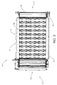
図2に示す通り、装置10は、アノードパネル12、長手方向ビーム16、横方向および長手方向に置かれたアノードユニット32、供給システム25、入口15、出口17、シリンダ22、および駆動モータ24を備える。
As shown in FIG. 2, the
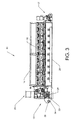
図3に示す通り、装置10は入口15、出口17、長手方向ビーム16および20の構成、長手方向に置かれたアノードユニット32、スプレーバー35、フランジベアリング33を含み、該フランジベアリング33はローラ34の固定および調整を可能にする。ローラ34は、コンベア(図示せず)の案内および伸張を可能にする。
As shown in FIG. 3, the
図4は、装置10の横軸線におけるアノードユニット32のレイアウト、ビーム16および20、駆動モータ24、スプレーバー35、ならびにスクラッパ27の配置を示す。二次ビーム18はアノードユニット32を支持する。
FIG. 4 shows the layout of the
図5はアノードユニット32の拡大図を示し、その2つの空気圧アクチュエータ50のレイアウト、およびアノード53を示す。アノード53は、絶縁板56および金属板54を含む。装置に使用されるアノードユニット32の量をユーザが修正することができるように、アノードユニット32は、装置10内に係脱可能に挿入されるように適応される。支持部材51は、案内ブラケット52および金属板58を含む。金属板58は、案内ブラケット52によって装置10の支持金属構造に固定されるように適応される。金属板58は、案内シリンダ60を介してアノードユニット32の上部に、空気圧アクチュエータ50を取り付けることを可能にする。空気圧アクチュエータ50は、案内シリンダ62を介して絶縁板56を取り付けることを可能にする。ばね64が金属板58および絶縁板56に取り付けられる。ばね64は、アノード53を上昇位置すなわち処理対象の物質が圧搾されない位置に付勢することを可能にする。電気コネクタ66が絶縁板56に固定され、アノード53の電気接続を可能にする。
FIG. 5 shows an enlarged view of the
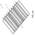
図6に示す通り、装置10は、カソードパネル14に配置された廃物収集および排出システム70を備える。図6Aで、収集および排出システム70が廃物収集パン72および廃物排出管74を含むことが分かる。
As shown in FIG. 6, the
図7に示す通り、供給システム25は、ホッパ80のようなハウジング、上部ローラ90および92(図7A参照)の固定を可能にする上部フランジベアリング82を含む。下部フランジベアリング84は、下部ローラ94および96(図7A参照)を固定するために使用される。駆動モータ86は上部ローラ90および92を回転させるために使用され、駆動モータ88は下部ローラ94および96を回転させるために使用される。
As shown in FIG. 7, the
図8に示す通り、装置100は、直列に配置された2つの重ね合わせモジュール104および106を備える。供給システム25は上部モジュール104の入口に配置され、移送および細断システム102は、処理および脱水された液体担持物質または物質を、さらなる処理のために下部モジュール106に移送することを可能にする。そのようなシステムは、処理された物質を細断して、次の処理のためにモジュール106に供給することを可能にする。
As shown in FIG. 8, the
図9に示す通り、装置200は、並列に配置された2つの重ね合わせモジュール204および206を備え、供給システム25はモジュール204および206の入口に配置される。
As shown in FIG. 9, the
液体担持物質の処理および脱水のための装置は、1つまたは複数のモジュールを備えることができる。モジュールは、特定の処理能力を有するユニットである。モジュールの数は、所望の処理容量に応じて変化する。各モジュールの動作条件は、独立して制御することができる。モジュールは相互に積み重ねることができる。それらは並列または直列に動作することができる(カスケードモード)。第1の状況で、各モジュールはそれ自体の供給システム(図9参照)を得る。第2の状況(図8参照)では、第1のモジュールだけが供給システムによって供給され、第2のモジュールは移送および細断システムによって供給される。この第1のモジュールによって処理された物質は、後で第2のモジュール等に移送される。物質は、異なるモジュールを進むにつれて処理され脱水される。 An apparatus for treatment and dehydration of a liquid support material may comprise one or more modules. A module is a unit having a specific processing capability. The number of modules varies depending on the desired processing capacity. The operating conditions of each module can be controlled independently. Modules can be stacked on top of each other. They can operate in parallel or in series (cascade mode). In the first situation, each module gets its own supply system (see FIG. 9). In the second situation (see FIG. 8), only the first module is supplied by the supply system and the second module is supplied by the transfer and shredding system. The material processed by the first module is later transferred to the second module or the like. The material is processed and dehydrated as it travels through different modules.
図1、5、および6に示す通り、モジュールは、上部パネル12(アノードパネル)および下部パネル14(カソードパネル)を含むことができる。アノードパネルは、アノードユニット32、長手方向ビーム16、側方ビーム18、電源の冷却システム、ガス回収システムおよび支持金属構造を含む。アノードユニット32は、アノードパネル内に横方向および長手方向に配置される。カソードパネル14は、有孔カソード19、コンベア13、長手方向ビーム20、廃物収集および排出システム70、真空システム(図示せず)、コンベア用の清掃および洗浄システム(図示せず)、水密性のための側板、ファブリックコンベア用の駆動モータ、ならびに支持金属構造を含む。コンベア13は、ステンレス鋼カソード19上に置かれたファブリックから作ることができる。カソード19は、処理対象の物質に加えられる圧力を支持することのできる金属構造によって支持することができる。清掃および洗浄システムはカソードパネル14に設置することができ、ファブリックコンベアにこびりついた処理後の物質を清掃し除去するために役立つことができる。電源は、アノードパネル12上に、もしくはモジュールの近傍に配置するか、または各アノードユニット32内に含めることができる。電源は、短絡を防止するために制御システムを具備する。
As shown in FIGS. 1, 5, and 6, the module can include an upper panel 12 (anode panel) and a lower panel 14 (cathode panel). The anode panel includes an
アノードユニット32は、不動の上部および可動の下部を含むことができる。不動の上部は、アノードユニット32を支持金属構造に固定するために、金属板58に固定されかつ側方ビーム18上を摺動する案内ブラケット52を含む。不動の上部はまた、金属板58に固定された2つの案内シリンダ60、および空気圧アクチュエータ50(図5参照)をも含むことができる。可動の下部は、電気絶縁および剛性化板56、不活性の安定な非消耗電極54、および案内シリンダ62を介して空気圧アクチュエータ50を取り付けるための取付けシステムを含むことができる。ばね64は金属板58および絶縁板56に固定され、可動の下部がその初期位置に戻ること(またはそれを上昇位置に付勢すること)を可能にする。電気コネクタ66はアノード53に固定される。アノードユニット32の可動の下部は、空気圧アクチュエータ50およびばね64によって不動の上部に取り付けられる。不活性の安定な非消耗電極は、金属酸化物で被覆された弁金属サブストレートを含むことができる。金属酸化物は、例えばTiO2、Ta2O5、TaO2、RuO2、IrO2、SnO2、Sb2O3、およびそれらの混合物から選択することができる。チタンを弁金属サブストレートとして使用することができる。例えば使用する電極は、酸化イリジウムと酸化タンタルの混合物で被覆されたチタンサブストレートとすることができる。ステンレス鋼もまた金属サブストレートとして使用することができる。電極は、導電性である準化学量論的酸化チタンを得ることを可能にする特定の温度で処理されたチタンを含むことができる。そのような酸化チタンはマグネリ相準化学量論的酸化チタンと呼ぶことができ、化学式TinO2n−1で表わされる。ここでnは4ないし10である。
The
各アノードユニット32は、平行六面体の形状とすることができる。各アノードユニットはそれ自体の電源を有することができる。所与のアノードユニットにおける処理のために必要な電圧、電流、および圧力は、固有かつ独立していることができる。空気圧アクチュエータ50は、所与のアノードユニットにおける処理に必要な圧力を発生させることができる。各アノードユニットは、所与のアノードユニットにおける処理のために必要な電力を発生させることが可能な、それ自体の電源を有することができる。アノードユニット32の可動の下部は、処理中の物質の変形に従動し、したがってアノードと処理された物質との間の略一定の接触を維持するのに効果的である。アノードユニットは相互に独立しており、異なる高さに配置することができる。
Each
図1ないし7Aに示す通り、供給システム25は、処理および脱水対象の物質を所与の厚さのケーキの形で、コンベア13上に拡散させる。供給システムは、物質をコンベア上に略均等に拡散させることができる。そのような供給システムは、物質をコンベア13上に実質的に定義された厚さに均等に堆積させることができることに加えて、供給システムは処理対象の物質を予備圧搾することができることにも注目されたい。したがって、移動可能な電極(アノード53)によって圧搾される前であっても、物質は供給システム25によって予備圧搾される。例えば、物質のそのような圧搾および均等な堆積は、物質に対する均等な電気的脱水処理を実行することを可能にする。コンベア13は、横方向に置かれたアノードユニット32から構成される少なくとも1つの列の下の処理対象の物質を移動させる。空気圧アクチュエータ50の作動によって、所与の圧力がこの物質に加えられる。物質を処理しかつ脱水するために、アノードユニットとカソード19との間に予め定められた時間、電圧が印加される。空気圧アクチュエータ50の減圧およびばね64の圧縮により、アノードユニットの可動の下部は上昇することができる。コンベア13の移動により、半処理された物質は次のアノードユニット列に移され、そこで該物質は特定の電圧、電流、および圧力によりさらに処理され、その間に、未処理の物質が第1アノードユニットの列に供給される。これは処理サイクルが終わるまで続く。
As shown in FIGS. 1-7A, the
処理され脱水された物質は次いで、装置10の出口17に配置されたシステムによって廃棄され細断される。廃物は、廃物収集および排出システム70によって有孔カソード19の下で回収される。発生したガスは装置10の上部で回収される。真空システム(図示せず)は任意選択的に、カソード19の下に設置される。このシステムは、コンベア13およびカソード19に残った廃物のより良好な除去を可能にする。コンベア13は連続的に出口17で清掃され、入口15で洗浄される。
The treated and dehydrated material is then discarded and shredded by a system located at the
少なくとも2つの動作モジュールが使用され、直列に配置される場合(図8のモジュール104および106を参照されたい)、細断システムを含む移送システム102は、細断され処理された物質をモジュールから別のモジュールに移送させる。
If at least two motion modules are used and placed in series (see
供給システム25は、実質的にファブリックコンベア13の幅全体にわたって、処理対象の物質を定められた厚さに均等に拡散させる。
The
供給システム25の上部で、分配手段(図示せず)は、実質的にホッパ80の全長にわたって物質を拡散することができる。この分配手段は、例えばスクリュまたは振動システムとすることができる。物は実質的にホッパ80の長さ全体にわたって分散されるので、物質の高さは均等化することができる。装置10のコンベアに均等に堆積した物質の厚さは、コンベアと下部ローラ94との間の距離を垂直方向に調整することによって調整される。処理対象の物質の性質に従って、ローラ94および96間の距離を変化させることによって、さらなる調整を行なうことができる。
At the top of the
上部ローラ間の距離は、下部ローラ間のそれより大きい。上部および下部ローラは二重の機能を有する。すなわち、それらは物質を駆動し、かつそれを圧搾させる。ローラの外面は、物質のより良好な供給を可能にするために、特定の粗さを有することができる。そのような表面仕上げは、物質とローラとの間のスリップを低減する。物質の駆動は、ローラとの表面接触に依存する。上部および下部ローラの速度は、物質の性質および乾燥度に従って選択される。装置10のコンベアの速度もまた、供給システムによって拡散または堆積することが要求される物質の量に従って選択される。
The distance between the upper rollers is greater than that between the lower rollers. The upper and lower rollers have a dual function. That is, they drive the material and squeeze it. The outer surface of the roller can have a certain roughness to allow a better supply of material. Such a surface finish reduces slip between the material and the roller. The driving of the material depends on the surface contact with the roller. The speed of the upper and lower rollers is selected according to the material properties and dryness. The speed of the conveyor of the
物質がホッパ80の長さ全体にわたって流入され、均等化されるときに、上部ローラ90および92は物質を圧搾し、下部ローラ94および96に向かって垂直方向に移動させる。そのような下部ローラは、物質のさらなる圧搾をもたらし、かつ装置10のコンベアに向かって物質を移動させる。ローラ94とコンベアとの間の距離は物質を圧搾させ、物質の最終厚さを画定する。供給システムは連続的に、またはバッチプロセスとして動作することができる。それはまた、レベルセンサおよびドライブを提供することによって自動化することもできる。
As material flows in and is equalized over the length of
所与の電圧が2つの電極間に印加されるときに、電圧損失が顕著である。この損失は、処理された物質の電気抵抗の上昇によって誘発される。この上昇は、一部には、アノード界面における処理済み物質中の電気絶縁クラストの形成、およびアノードの近傍における処理済み物質の水分の低下によると考えられる。電圧損失はエネルギ損失および処理品質の低下を暗示する。この問題を処理し、かつアノードから処理済み物質への電圧伝達を増強するために、2つの解決策を使用することができる。第一に、アノード‐物質界面に電解質を添加することができる。これはアノードの近傍における伝導度を改善し、また電圧損失を安定化し、それを処理中に低減されたレベルに維持するのに役立つ。第二に、機械的手段によってクラストを破砕することも可能である。これらの2つの解決策を両方使用することもできる。 The voltage loss is significant when a given voltage is applied between the two electrodes. This loss is induced by an increase in the electrical resistance of the treated material. This increase is believed to be due in part to the formation of an electrically insulating crust in the treated material at the anode interface and a reduction in the moisture of the treated material in the vicinity of the anode. Voltage loss implies energy loss and process quality degradation. Two solutions can be used to address this problem and to enhance voltage transfer from the anode to the treated material. First, an electrolyte can be added to the anode-material interface. This improves the conductivity in the vicinity of the anode and helps to stabilize the voltage loss and maintain it at a reduced level during processing. Secondly, it is possible to crush the crust by mechanical means. Both of these two solutions can also be used.
以下の実施例は非限定的に種々の実施形態を代表する。 The following examples represent, without limitation, various embodiments.
「パルプおよび製紙産業からのスラッジ」
二次スラッジ、ならびに一次および二次スラッジの両方を含む混合スラッジを試験した。
"Sludge from the pulp and paper industry"
Secondary sludge and mixed sludge containing both primary and secondary sludge were tested.
これらの試験を、図1に示すような装置で実行した。装置は5つのアノードユニットを含むものであった。 These tests were performed on an apparatus as shown in FIG. The apparatus contained 5 anode units.
この供給システムは、処理および脱水対象のスラッジを、実質的にろ過用ファブリックコンベアの幅全体に所与の厚さのケーキの形で均等に分配かつ拡散する。次いで、処理および電気的脱水プロセスを開始する。 This feeding system distributes and spreads the sludge to be treated and dewatered evenly in the form of a cake of a given thickness over substantially the entire width of the filtering fabric conveyor. The processing and electrical dehydration process is then started.
コンベアは、処理対象のスラッジを第1アノードユニットの下に移動させる。空気圧アクチュエータの作動によって、このスラッジに所与の圧力が加えられる。スラッジを処理かつ脱水するために、第1アノードユニットとカソードとの間に、予め定められた時間、電圧が印加される。空気圧アクチュエータの減圧およびばねの圧縮により、第1アノードユニットの可動の下部が上昇する。コンベアの移動により、半処理されたスラッジが第2のアノードユニットに移され、そこで該スラッジは特定の電圧、電流、および圧力によりさらに処理され、その間に、未処理のスラッジが第1アノードユニットに供給される。これは処理サイクルが終わるまで続く。 The conveyor moves the sludge to be processed under the first anode unit. Actuation of the pneumatic actuator applies a given pressure to this sludge. In order to treat and dewater the sludge, a voltage is applied between the first anode unit and the cathode for a predetermined time. Due to the reduced pressure of the pneumatic actuator and the compression of the spring, the movable lower part of the first anode unit is raised. Due to the movement of the conveyor, the semi-treated sludge is transferred to the second anode unit, where it is further treated with a specific voltage, current and pressure, during which untreated sludge enters the first anode unit. Supplied. This continues until the end of the processing cycle.
「パルプおよび製紙産業の二次スラッジ」
この実施例では、各バッチ(アノードユニット)の処理に必要な時間は約130秒であった。全処理プロセスは約11.5分かかった。プロセス時間は、アノードユニットを上昇させるために要する時間を含む。処理中に使用した電圧は60ボルトであった。
“Secondary sludge in the pulp and paper industry”
In this example, the time required for processing each batch (anode unit) was about 130 seconds. The entire treatment process took about 11.5 minutes. The process time includes the time required to raise the anode unit. The voltage used during processing was 60 volts.
非処理スラッジの乾燥度は約12%であったが、結果的に得られた電気脱水後のスラッジの乾燥度は約44%であった。 The dryness of the untreated sludge was about 12%, but the resulting dryness of the sludge after electro-dehydration was about 44%.
表1および2は、5つのアノードユニットの各々に対するモニタリング結果および実施例1で得られた種々のパラメータを示す。

実施例2では、混合したパルプおよび製紙スラッジ(約50%の一次スラッジおよび50%の二次スラッジ)を使用した。非処理スラッジの乾燥度は約15%であったが、電気的脱水されたスラッジの乾燥度は約42%であった。
「都市二次スラッジ」
この実施例では、都市二次スラッジを処理した。前の実施例と同じ装置を使用した。各バッチ(アノードユニット)の処理に必要な時間は約180秒であった。全処理プロセスは約15分かかった。プロセス時間は、アノードユニットを上昇させるために要する時間を含む。処理中に使用した電圧は60ボルトであった。
"City secondary sludge"
In this example, urban secondary sludge was treated. The same equipment as in the previous example was used. The time required for processing each batch (anode unit) was about 180 seconds. The entire treatment process took about 15 minutes. The process time includes the time required to raise the anode unit. The voltage used during processing was 60 volts.
スラッジ処理中に、3回のサンプリングを実行した。各サンプリングで、サルモネラ菌および糞便大腸菌の分析のために、未処理スラッジ、処理済みスラッジ、および発生した廃物をサンプリングした。 Three samplings were performed during the sludge treatment. At each sampling, untreated sludge, treated sludge, and generated waste were sampled for analysis of Salmonella and fecal E. coli.
表5および6は、5つのアノードユニットの各々について、第1のサンプリングで採取されたスラッジの処理中に得られたモニタリング結果および種々のパラメータを示す。 Tables 5 and 6 show the monitoring results and various parameters obtained during the treatment of the sludge collected in the first sampling for each of the five anode units.
表7ないし9は、第1、第2、および第3のサンプリング中に採取したサンプルの微生物の減少を示す。 Tables 7-9 show the microbial reduction of samples taken during the first, second and third sampling.
「第1のサンプリング」
「第2のサンプリング」
「第3のサンプリング」
表7ないし9から分かるように、処理後に糞便大腸菌およびサルモネラ菌のレベルは低下した。また、発生した廃物中の大腸菌およびサルモネラ菌のレベルは、検出限界より低いことも分かる。 As can be seen from Tables 7-9, the levels of fecal E. coli and Salmonella decreased after treatment. It can also be seen that the levels of E. coli and Salmonella in the generated waste are below the detection limit.
本発明の装置およびプロセスにより、スラッジのような物質を効率的に脱水し、かつ高い乾燥度を得ることができることが示された。さらに、装置およびプロセスは、微粒子から構成される物質の脱水を可能にする。また、そのような装置およびプロセスが、微生物の不活化および/または破壊に効果的であることも示された。 It has been shown that the apparatus and process of the present invention can efficiently dehydrate materials such as sludge and achieve high dryness. Furthermore, the apparatus and process allow dehydration of materials composed of particulates. Such devices and processes have also been shown to be effective in inactivating and / or destroying microorganisms.
装置およびプロセスは、処理中に各アノードユニットの処理のパラメータ(電圧、電流、および圧力)のみならず、処理および脱水対象の物質の厚さをも制御することができる。そのような制御は、良好な品質の処理をもたらし、かつ電力消費を制御することをも可能にする。 The apparatus and process can control not only the processing parameters (voltage, current, and pressure) of each anode unit during processing, but also the thickness of the material to be processed and dehydrated. Such control results in good quality processing and also makes it possible to control power consumption.
装置およびプロセスは柔軟であり、可変乾燥度を持つ様々な物質を処理することができる。さらに、装置およびプロセスは捕獲率を持つことを可能にし、したがって廃物は低量の懸濁液中全固形物(TSS)を提示する。 The apparatus and process are flexible and can handle a variety of materials with variable dryness. In addition, the apparatus and process can have a capture rate, so the waste presents a low amount of total solids (TSS) in suspension.
装置およびプロセスは、物質の処理中に発生するガスの排出を可能にする。 The apparatus and process allow for the emission of gases that are generated during the processing of materials.
装置は単純な機械的構造を有し、処理対象の物質の特徴に従ってパラメータの自動調整をもたらす。 The device has a simple mechanical structure and provides automatic adjustment of parameters according to the characteristics of the material to be processed.
本発明をその特定の実施形態に関連して説明したが、さらなる変化が可能であり、本願は、本発明が関係する技術分野で公知または習慣的な常法に該当するような、かつ本書で前述した基本的な特徴に適用されるような、かつ添付する特許請求の範囲に従うような本開示からの逸脱を含め、一般的に本発明の原理に従う発明の任意の変形、使用、または適応を含むつもりである。 Although the present invention has been described with reference to specific embodiments thereof, further variations are possible, and the present application is hereby intended to fall within the technical fields known or customary in the art to which the present invention pertains, and in this document. Any variation, use, or adaptation of the invention generally in accordance with the principles of the invention, including deviations from the present disclosure as applied to the basic features described above and in accordance with the appended claims. I intend to include it.
Claims (141)
前記装置内に係脱可能に挿入されるように適応された支持部材と、
少なくとも1つの電極と、
前記支持部材および前記少なくとも1つの電極に接続され、前記少なくとも1つの電極を予め定められた方向に移動させ、かつ前記物質に圧力を加えるための手段と、
を備えた電極ユニット。 An electrode unit for use in an apparatus for increasing the dryness of a substance,
A support member adapted to be removably inserted into the device;
At least one electrode;
Means connected to the support member and the at least one electrode for moving the at least one electrode in a predetermined direction and applying pressure to the substance;
Electrode unit with
請求項88に記載のプロセス。 The pressure applied to the substance is constant,
90. The process of claim 88.
入口および出口を含むハウジングと、
前記ハウジング内に前記出口に隣接して配置された少なくとも2つの回転手段と、
を備え、前記回転手段が前記物質を圧搾しかつ略垂直方向に出口に向かって移動させるように適応され、前記回転手段の1つが、前記回転手段のうちの少なくとも1つの他の回転手段より出口の近くにあり、前記出口の近くにある前記回転手段が、前記出口から送り出される物質の厚さを制御するために、略垂直に移動するように適応されて成る、供給システム。 A supply system for use in an apparatus for increasing the dryness of a substance,
A housing including an inlet and an outlet;
At least two rotating means disposed in the housing adjacent to the outlet;
The rotating means is adapted to squeeze the substance and move it in a substantially vertical direction towards the outlet, wherein one of the rotating means is more outlet than at least one other rotating means of the rotating means. And the rotating means near the outlet is adapted to move substantially vertically to control the thickness of the material delivered from the outlet.
入口および出口を含み、前記出口が前記コンベアに隣接して配置されるように適応され、前記供給システムを介して前記コンベア上に拡散される物質を受け取るように適応されたハウジングと、
前記出口に隣接して配置された少なくとも2つの回転手段と、
を備え、前記回転手段が前記物質を圧搾しかつ下方に出口まで移動させるように適応され、前記回転手段が各々前記出口から異なる垂直距離に配置され、前記出口に最も近い前記回転手段が、前記出口を通して前記コンベア上に拡散される物質の厚さを制御するために、略垂直方向に移動するように適応されて成る、供給システム。 A supply system for use in combination with a conveyor,
A housing including an inlet and an outlet, wherein the outlet is adapted to be disposed adjacent to the conveyor and adapted to receive material diffused onto the conveyor via the supply system;
At least two rotating means arranged adjacent to the outlet;
The rotating means is adapted to squeeze the substance and move it down to the outlet, wherein the rotating means are each arranged at different vertical distances from the outlet, and the rotating means closest to the outlet comprises: A feeding system adapted to move in a substantially vertical direction to control the thickness of the material diffused on the conveyor through the outlet.
入口および出口を含み、前記物質を受け取るように適応されたハウジングと、
前記ハウジング内に前記出口に隣接して配置された少なくとも2つの回転手段と、
を備え、前記回転手段が前記物質を圧搾しかつ前記出口へ移動させるように適応され、前記回転手段の1つが、前記回転手段のうちの少なくとも1つの他の回転手段より前記出口の近くにあり、前記出口に近い前記回転手段が、前記出口を通して拡散される物質の厚さを制御するために、略軸線に沿って移動するように適応されて成る、供給システム。 A supply system for diffusing a substance,
A housing including an inlet and an outlet and adapted to receive the substance;
At least two rotating means disposed in the housing adjacent to the outlet;
The rotating means is adapted to squeeze and move the substance to the outlet, one of the rotating means being closer to the outlet than at least one other rotating means of the rotating means The feeding system, wherein the rotating means close to the outlet is adapted to move substantially along an axis to control the thickness of the material diffused through the outlet.
協働ローラ間に物質を導入して、前記物質を圧搾させ、かつ前記物質を実質的に下方に前記サブストレートに向かって移動させるステップ、
を含み、
前記物質を前記ローラ間に導入する前に、前記ローラの1つから前記サブストレートまでの垂直距離が他のローラから前記サブストレートまでの垂直距離より小さい位置であって、拡散される物質が予め定められた厚さを有するようになる位置を選択するために、前記ローラの1つが垂直軸線に沿って実質的に移動すること、を特徴とする方法。 A method for diffusing a substance on a substrate, comprising:
Introducing a substance between cooperating rollers to squeeze the substance and move the substance substantially downwardly toward the substrate;
Including
Before introducing the substance between the rollers, the vertical distance from one of the rollers to the substrate is smaller than the vertical distance from the other roller to the substrate, A method characterized in that one of said rollers is moved substantially along a vertical axis in order to select a position that will have a defined thickness.
Applications Claiming Priority (3)
| Application Number | Priority Date | Filing Date | Title |
|---|---|---|---|
| US80471306P | 2006-06-14 | 2006-06-14 | |
| US86229406P | 2006-10-20 | 2006-10-20 | |
| PCT/CA2007/001052 WO2007143840A1 (en) | 2006-06-14 | 2007-06-13 | Processes and apparatuses for treating and/or increasing dryness of a substance |
Publications (2)
| Publication Number | Publication Date |
|---|---|
| JP2009539587A true JP2009539587A (en) | 2009-11-19 |
| JP2009539587A5 JP2009539587A5 (en) | 2012-05-17 |
Family
ID=38831366
Family Applications (1)
| Application Number | Title | Priority Date | Filing Date |
|---|---|---|---|
| JP2009514603A Pending JP2009539587A (en) | 2006-06-14 | 2007-06-13 | Process and apparatus for treating a substance and / or increasing its dryness |
Country Status (7)
| Country | Link |
|---|---|
| US (2) | US8454814B2 (en) |
| EP (1) | EP2043765A4 (en) |
| JP (1) | JP2009539587A (en) |
| KR (1) | KR20090027602A (en) |
| CN (1) | CN101472669A (en) |
| CA (1) | CA2627221C (en) |
| WO (1) | WO2007143840A1 (en) |
Cited By (3)
| Publication number | Priority date | Publication date | Assignee | Title |
|---|---|---|---|---|
| JP2011072863A (en) * | 2009-09-29 | 2011-04-14 | Kurita Water Ind Ltd | Electroosmotic dewatering apparatus |
| JP2011212525A (en) * | 2010-03-31 | 2011-10-27 | Kurita Water Ind Ltd | Electro-osmotic dewatering method and apparatus |
| JP2012529985A (en) * | 2009-06-15 | 2012-11-29 | ドンイルキャンバスエンジニアリング株式会社 | Electroosmotic sludge weight loss device |
Families Citing this family (14)
| Publication number | Priority date | Publication date | Assignee | Title |
|---|---|---|---|---|
| US20080196854A1 (en) * | 2005-06-16 | 2008-08-21 | Helmut Figalist | Sieve Mechanism For the Production of Paper, and Method For the Treatment of Non-Woven Fibers |
| US20120055797A1 (en) * | 2008-12-11 | 2012-03-08 | Gl&V Canada Inc. | Method and apparatus for increasing the efficiency of electro-dewatering |
| KR100956613B1 (en) * | 2009-08-18 | 2010-05-11 | (주)동일캔바스엔지니어링 | Electro-penetrative type sludge decrement apparatus having improving insulation safety electrode plate |
| US8772004B2 (en) * | 2009-06-25 | 2014-07-08 | Old Dominion University Research Foundation | System and method for high-voltage pulse assisted aggregation of algae |
| CN102506569B (en) * | 2011-11-30 | 2016-01-20 | 宜兴能达环保科技有限公司 | A kind of electroosmotic dewatering method of water-containing materials and device |
| US8709258B2 (en) | 2012-07-12 | 2014-04-29 | Heliae Development, Llc | Patterned electrical pulse microorganism aggregation |
| US8702991B2 (en) | 2012-07-12 | 2014-04-22 | Heliae Development, Llc | Electrical microorganism aggregation methods |
| US8673154B2 (en) | 2012-07-12 | 2014-03-18 | Heliae Development, Llc | Tunable electrical field for aggregating microorganisms |
| US8668827B2 (en) | 2012-07-12 | 2014-03-11 | Heliae Development, Llc | Rectangular channel electro-acoustic aggregation device |
| US8709250B2 (en) | 2012-07-12 | 2014-04-29 | Heliae Development, Llc | Tubular electro-acoustic aggregation device |
| CN103570209A (en) * | 2012-07-31 | 2014-02-12 | 西门子公司 | Electric dehydration device |
| CN110563092A (en) * | 2018-06-05 | 2019-12-13 | 山东祥弘节能环保科技有限公司 | Rotatable electrode electrochemical water treatment device |
| KR102376014B1 (en) * | 2019-07-05 | 2022-03-18 | 경상국립대학교산학협력단 | Antimicrobial paper using leaves extraction in Rubus Coreanus Miq(Rubus Occidentalis). and method for manufacturing thereof |
| CN110440536B (en) * | 2019-08-02 | 2020-10-13 | 东阳市俊华电器销售有限公司 | Physical extrusion type textile cloth drying equipment |
Citations (6)
| Publication number | Priority date | Publication date | Assignee | Title |
|---|---|---|---|---|
| JPS6369518A (en) * | 1986-09-11 | 1988-03-29 | Fuji Electric Co Ltd | Pressurized electric permeation dehydrator |
| JPH0413003B2 (en) * | 1984-07-04 | 1992-03-06 | Fuji Denki Sogo Kenkyusho Kk | |
| JPH054100A (en) * | 1991-06-26 | 1993-01-14 | Shinko Pantec Co Ltd | Electroosmosis dehydrating method for sludge |
| JPH0615706U (en) * | 1992-07-21 | 1994-03-01 | 株式会社クボタ | Belt dehydrator |
| JPH06218397A (en) * | 1993-01-27 | 1994-08-09 | Ichikawa Woolen Textile Co Ltd | Method and device for drying and firing sludge |
| JPH0773646B2 (en) * | 1987-07-24 | 1995-08-09 | 神鋼パンテック株式会社 | Batch electroosmosis dehydration method |
Family Cites Families (28)
| Publication number | Priority date | Publication date | Assignee | Title |
|---|---|---|---|---|
| US894070A (en) * | 1905-06-27 | 1908-07-21 | Hoechst Ag | Extraction of water or other liquid from mineral, vegetable, and animal substances. |
| GB1418577A (en) | 1973-05-29 | 1975-12-24 | Machinenfabriek W Hubert Co Bv | Method and apparatus for dewatering sludge |
| US4001100A (en) * | 1975-01-03 | 1977-01-04 | James Livesey Haydock | Treatment of suspensions and slurries by electrophoresis and electro-osmosis |
| CH583404A5 (en) | 1975-03-18 | 1976-12-31 | Patelhold Patentverwertung | |
| US4135307A (en) * | 1976-06-11 | 1979-01-23 | Candor James T | Method and apparatus for removing liquid from liquid bearing material |
| US4244804A (en) * | 1979-01-15 | 1981-01-13 | Innova, Inc. | Slime and sludge dewatering |
| US4671874A (en) | 1981-04-06 | 1987-06-09 | Champion International Corporation | Continuous dewatering apparatus |
| US4680104A (en) * | 1984-06-11 | 1987-07-14 | J. M. Huber Corporation | Apparatus for dewatering clay filter cake |
| US5092974A (en) * | 1990-01-25 | 1992-03-03 | Shinko Pantec Co., Ltd. | Electrode and method for compressive and electro-osmotic dehydration |
| JPH0413003A (en) | 1990-04-28 | 1992-01-17 | Toyotomi Co Ltd | Kerosene burner |
| US5225209A (en) * | 1990-05-12 | 1993-07-06 | Rheon Automatic Machinery Co., Ltd. | Apparatus for stretching dough |
| US5401375A (en) | 1991-05-09 | 1995-03-28 | Fuji Electric Co., Ltd. | Electro-endosmosis type dehydrator |
| JPH057738A (en) * | 1991-07-02 | 1993-01-19 | Kubota Corp | Dehydrator |
| JPH0582490A (en) * | 1991-09-19 | 1993-04-02 | Hitachi Ltd | Method and device for selective etching |
| JP2575573B2 (en) | 1992-07-01 | 1997-01-29 | 株式会社ソディック | Screw drive for injection molding machine |
| US5656165A (en) * | 1993-02-23 | 1997-08-12 | Yamamoto Kogyo Kabushiki Kaisha | Dewatering apparatus of filter belt type |
| JPH0773646A (en) | 1993-06-24 | 1995-03-17 | Sony Corp | Data cartridge |
| FI103108B1 (en) * | 1994-08-29 | 1999-04-30 | Valmet Flootek Oy | Process for separating water from sludge |
| GB9420216D0 (en) | 1994-10-06 | 1994-11-23 | Scapa Group Plc | Dewatering process |
| AU7214196A (en) | 1995-09-26 | 1997-04-17 | Seprotech (Proprietary) Limited | Electro-osmotic dewatering of sludges |
| AUPQ741800A0 (en) | 2000-05-10 | 2000-06-01 | Commonwealth Scientific And Industrial Research Organisation | Apparatus for electrodewatering by filtration |
| IT1318233B1 (en) * | 2000-07-24 | 2003-07-28 | De Nora Elettrodi Spa | MOTORIZED DEVICE FOR THE ADJUSTMENT OF THE INTERELECTRODICAL DISTANCE IN MERCURY CATHODE ELECTROLYSIS CELLS. |
| US7935236B2 (en) * | 2002-05-09 | 2011-05-03 | The United States Of America As Represented By The Secretary Of The Army | Electro-osmotic pulse (EOP) treatment method |
| CA2437245A1 (en) * | 2003-08-11 | 2005-02-11 | Les Technologies Elcotech Inc. | Apparatus for treating high dryness sludge |
| GB0323068D0 (en) * | 2003-10-01 | 2003-11-05 | Nuground Ltd | Dewatering treatment system and method |
| EP1673214B1 (en) * | 2003-10-15 | 2013-04-17 | Nordic Water Products AB | Apparatus and method for treating sludge |
| CA2666822A1 (en) * | 2006-10-20 | 2008-04-24 | Gl&V Canada Inc. | Adjustable roller apparatus for spreading substances |
| US20120055797A1 (en) * | 2008-12-11 | 2012-03-08 | Gl&V Canada Inc. | Method and apparatus for increasing the efficiency of electro-dewatering |
-
2007
- 2007-06-13 EP EP07719968A patent/EP2043765A4/en not_active Withdrawn
- 2007-06-13 WO PCT/CA2007/001052 patent/WO2007143840A1/en active Application Filing
- 2007-06-13 JP JP2009514603A patent/JP2009539587A/en active Pending
- 2007-06-13 CN CNA2007800223328A patent/CN101472669A/en active Pending
- 2007-06-13 KR KR1020087015683A patent/KR20090027602A/en not_active Application Discontinuation
- 2007-06-13 US US12/304,472 patent/US8454814B2/en not_active Expired - Fee Related
- 2007-06-13 CA CA002627221A patent/CA2627221C/en not_active Expired - Fee Related
-
2013
- 2013-05-08 US US13/889,776 patent/US20130313117A1/en not_active Abandoned
Patent Citations (6)
| Publication number | Priority date | Publication date | Assignee | Title |
|---|---|---|---|---|
| JPH0413003B2 (en) * | 1984-07-04 | 1992-03-06 | Fuji Denki Sogo Kenkyusho Kk | |
| JPS6369518A (en) * | 1986-09-11 | 1988-03-29 | Fuji Electric Co Ltd | Pressurized electric permeation dehydrator |
| JPH0773646B2 (en) * | 1987-07-24 | 1995-08-09 | 神鋼パンテック株式会社 | Batch electroosmosis dehydration method |
| JPH054100A (en) * | 1991-06-26 | 1993-01-14 | Shinko Pantec Co Ltd | Electroosmosis dehydrating method for sludge |
| JPH0615706U (en) * | 1992-07-21 | 1994-03-01 | 株式会社クボタ | Belt dehydrator |
| JPH06218397A (en) * | 1993-01-27 | 1994-08-09 | Ichikawa Woolen Textile Co Ltd | Method and device for drying and firing sludge |
Cited By (3)
| Publication number | Priority date | Publication date | Assignee | Title |
|---|---|---|---|---|
| JP2012529985A (en) * | 2009-06-15 | 2012-11-29 | ドンイルキャンバスエンジニアリング株式会社 | Electroosmotic sludge weight loss device |
| JP2011072863A (en) * | 2009-09-29 | 2011-04-14 | Kurita Water Ind Ltd | Electroosmotic dewatering apparatus |
| JP2011212525A (en) * | 2010-03-31 | 2011-10-27 | Kurita Water Ind Ltd | Electro-osmotic dewatering method and apparatus |
Also Published As
| Publication number | Publication date |
|---|---|
| CA2627221A1 (en) | 2007-12-21 |
| KR20090027602A (en) | 2009-03-17 |
| EP2043765A1 (en) | 2009-04-08 |
| US20100163428A1 (en) | 2010-07-01 |
| CN101472669A (en) | 2009-07-01 |
| US8454814B2 (en) | 2013-06-04 |
| US20130313117A1 (en) | 2013-11-28 |
| EP2043765A4 (en) | 2012-10-10 |
| WO2007143840A1 (en) | 2007-12-21 |
| CA2627221C (en) | 2009-12-22 |
Similar Documents
| Publication | Publication Date | Title |
|---|---|---|
| JP2009539587A (en) | Process and apparatus for treating a substance and / or increasing its dryness | |
| US4244804A (en) | Slime and sludge dewatering | |
| JP5564877B2 (en) | Electroosmosis dehydrator | |
| US4919775A (en) | Method and apparatus for electrolytic treatment of sludge | |
| WO2018034300A1 (en) | Combined dehydration device | |
| US7578918B2 (en) | Process and apparatus for treating sludge | |
| US8672141B2 (en) | Solid-liquid separating system | |
| JP4651045B2 (en) | Sludge dewatering equipment | |
| JP2003245509A (en) | Concentrator, continuous compression dehydrator and moving dehydration vehicle | |
| JP5913698B1 (en) | Electroosmotic rotary pressure dehydrator | |
| WO2016057392A1 (en) | Continuous electrokinetic dewatering of phosphatic clay suspensions | |
| US20100224497A1 (en) | Device and method for the extraction of metals from liquids | |
| JP2011072862A (en) | Electroosmotic dewatering method and apparatus | |
| CN107381996B (en) | Electroosmosis filter-pressing cooperated sludge dewatering device | |
| JPH0685845B2 (en) | Electro-osmotic dehydrator | |
| US5259940A (en) | Apparatus and method for removing liquid from liquid bearing material | |
| KR970006504B1 (en) | Sludge dehydration apparatus | |
| EP1642868A1 (en) | Process and apparatus for treating sludge | |
| JPS63256112A (en) | Electroosmotic dehydrator | |
| JPS6159164B2 (en) | ||
| JPH042286B2 (en) | ||
| JP2011050844A (en) | Electro-osmotic dewatering method and apparatus | |
| JP2014188504A (en) | Method for detecting calcium scale deposition of electroosmosis dewatering device, and method for cleaning the device | |
| JP2012179572A (en) | Electro-osmotic dewatering method and apparatus | |
| WO1997011767A1 (en) | Electro-osmotic dewatering of sludges |
Legal Events
| Date | Code | Title | Description |
|---|---|---|---|
| A521 | Written amendment |
Free format text: JAPANESE INTERMEDIATE CODE: A523 Effective date: 20091015 |
|
| A621 | Written request for application examination |
Free format text: JAPANESE INTERMEDIATE CODE: A621 Effective date: 20091015 |
|
| A711 | Notification of change in applicant |
Free format text: JAPANESE INTERMEDIATE CODE: A711 Effective date: 20111026 |
|
| A521 | Written amendment |
Free format text: JAPANESE INTERMEDIATE CODE: A821 Effective date: 20111026 |
|
| A521 | Written amendment |
Free format text: JAPANESE INTERMEDIATE CODE: A523 Effective date: 20120319 |
|
| A131 | Notification of reasons for refusal |
Free format text: JAPANESE INTERMEDIATE CODE: A131 Effective date: 20120717 |
|
| A601 | Written request for extension of time |
Free format text: JAPANESE INTERMEDIATE CODE: A601 Effective date: 20121015 |
|
| A602 | Written permission of extension of time |
Free format text: JAPANESE INTERMEDIATE CODE: A602 Effective date: 20121022 |
|
| A601 | Written request for extension of time |
Free format text: JAPANESE INTERMEDIATE CODE: A601 Effective date: 20121115 |
|
| A602 | Written permission of extension of time |
Free format text: JAPANESE INTERMEDIATE CODE: A602 Effective date: 20121122 |
|
| A521 | Written amendment |
Free format text: JAPANESE INTERMEDIATE CODE: A523 Effective date: 20121213 |
|
| A02 | Decision of refusal |
Free format text: JAPANESE INTERMEDIATE CODE: A02 Effective date: 20131008 |