JP2009536339A - Optical probe - Google Patents
Optical probe Download PDFInfo
- Publication number
- JP2009536339A JP2009536339A JP2009508548A JP2009508548A JP2009536339A JP 2009536339 A JP2009536339 A JP 2009536339A JP 2009508548 A JP2009508548 A JP 2009508548A JP 2009508548 A JP2009508548 A JP 2009508548A JP 2009536339 A JP2009536339 A JP 2009536339A
- Authority
- JP
- Japan
- Prior art keywords
- optical
- optical probe
- waveguide
- detecting
- probe
- Prior art date
- Legal status (The legal status is an assumption and is not a legal conclusion. Google has not performed a legal analysis and makes no representation as to the accuracy of the status listed.)
- Pending
Links
Images


Classifications
-
- G—PHYSICS
- G01—MEASURING; TESTING
- G01N—INVESTIGATING OR ANALYSING MATERIALS BY DETERMINING THEIR CHEMICAL OR PHYSICAL PROPERTIES
- G01N21/00—Investigating or analysing materials by the use of optical means, i.e. using sub-millimetre waves, infrared, visible or ultraviolet light
- G01N21/62—Systems in which the material investigated is excited whereby it emits light or causes a change in wavelength of the incident light
- G01N21/63—Systems in which the material investigated is excited whereby it emits light or causes a change in wavelength of the incident light optically excited
- G01N21/64—Fluorescence; Phosphorescence
- G01N21/645—Specially adapted constructive features of fluorimeters
-
- G—PHYSICS
- G01—MEASURING; TESTING
- G01N—INVESTIGATING OR ANALYSING MATERIALS BY DETERMINING THEIR CHEMICAL OR PHYSICAL PROPERTIES
- G01N21/00—Investigating or analysing materials by the use of optical means, i.e. using sub-millimetre waves, infrared, visible or ultraviolet light
- G01N21/84—Systems specially adapted for particular applications
- G01N21/85—Investigating moving fluids or granular solids
- G01N21/8507—Probe photometers, i.e. with optical measuring part dipped into fluid sample
-
- G—PHYSICS
- G01—MEASURING; TESTING
- G01N—INVESTIGATING OR ANALYSING MATERIALS BY DETERMINING THEIR CHEMICAL OR PHYSICAL PROPERTIES
- G01N21/00—Investigating or analysing materials by the use of optical means, i.e. using sub-millimetre waves, infrared, visible or ultraviolet light
- G01N21/62—Systems in which the material investigated is excited whereby it emits light or causes a change in wavelength of the incident light
- G01N21/63—Systems in which the material investigated is excited whereby it emits light or causes a change in wavelength of the incident light optically excited
- G01N21/64—Fluorescence; Phosphorescence
- G01N21/645—Specially adapted constructive features of fluorimeters
- G01N2021/6463—Optics
Abstract
サンプルが放射する光を検出するための光学プローブが開示される。光学プローブは、パラボラ状の光導波路と、取り外し可能な要素を有し、光導波路に接続可能な透光性センサ支持体を保持するよう構成された外側ハウジングと、を具える。光学プローブはまた、少なくとも1つの分析対象の検出を行うための検出物質を具える。励起源は、検出物質を励起するよう構成される。光学プローブにはさらに、放射光を検出する測定用の光検出器が組み込まれる。 An optical probe for detecting light emitted by a sample is disclosed. The optical probe comprises a parabolic light guide and an outer housing having removable elements and configured to hold a translucent sensor support connectable to the light guide. The optical probe also includes a detection substance for detecting at least one analyte. The excitation source is configured to excite the detection substance. The optical probe further incorporates a measurement photodetector for detecting the emitted light.
Description
本発明の開示は、概して誘電体界面で発生する光を捕集するための光学センサ・プローブの分野に関し、特に、誘電体界面で発生する光を効率的に捕集ために最適化されたパラボラ状の光導波路(optical waveguide)を用いる光学センサ・プローブに関するものである。 The present disclosure relates generally to the field of optical sensor probes for collecting light generated at a dielectric interface, and more particularly, to a parabolic optimized for efficiently collecting light generated at a dielectric interface. The present invention relates to an optical sensor / probe that uses an optical waveguide.
光学センサは、例えば生物医学、環境および食品包装を含む産業の広範な分野にわたって広く使用されている。発光に基づく(luminescence-based)光学センサは、分析対象が誘起する(analyte-induced)発光信号の変化を検出する。かかる変化は、酸素、二酸化炭素、pHおよび塩化物のセンサを含む広範な光学・化学センサの場合、分析対象が感応する発光化合物(analyte-sensitive luminescent compound)からの光の、分析対象が誘起する消光に起因してもたらされる。これらの場合、発光性化合物は、多孔性の固体の基質(solid matrix)に封入され、薄膜として支持体上に付着(deposit)させることができる。あるいは、発光に基づく光学センサは、適切な受容分子を用いる表面に対する、対象とするひ分析物の結合に基づいたものであってもよい。発光性は、発光性ラベルを介してかかるシステムに付与される。発光性ラベルは、分析対象自体に付けられるものでもよいし、あるいは表面に結合する分析対象に結合する付加的な分子に付けられるものでもよい。発光のレベルの変化は、表面に結合する分析対象の濃度の変化を表すものとなる。この手法は、発光に基づく光学バイオセンサの開発に通常用いられている。 Optical sensors are widely used across a wide range of industries including, for example, biomedical, environmental and food packaging. A luminescence-based optical sensor detects a change in an luminescence signal that is analyzed by an analysis target. Such changes are triggered by the analyte of light from an analyte-sensitive luminescent compound for a wide range of optical and chemical sensors, including oxygen, carbon dioxide, pH and chloride sensors. This is caused by quenching. In these cases, the luminescent compound can be encapsulated in a porous solid matrix and deposited as a thin film on a support. Alternatively, the luminescence-based optical sensor may be based on binding of the analyte of interest to a surface using a suitable acceptor molecule. Luminescence is imparted to such systems via a luminescent label. The luminescent label can be attached to the analyte itself, or it can be attached to additional molecules that bind to the analyte bound to the surface. A change in the level of luminescence represents a change in the concentration of the analyte bound to the surface. This technique is commonly used in the development of optical biosensors based on luminescence.
受容体分子に結合した分析対象分子の濃度を感度高く測定するためには、表面結合分子に由来する発光のみを検出することが必要となる。これに続いて、表面上の環境内の非結合分子からの信号を排除しつつ、表面の近くに結合した分子からの発光を選択的に検出する測定タスクが行われる。この検出原理は、薄膜をベースとした光化学センサにも関連する。 In order to measure with high sensitivity the concentration of the analyte molecule bound to the receptor molecule, it is necessary to detect only the luminescence originating from the surface bound molecule. This is followed by a measurement task that selectively detects luminescence from molecules bound near the surface while eliminating signals from unbound molecules in the environment on the surface. This detection principle is also relevant for photochemical sensors based on thin films.
発光を効率的に検出し、効率的な光化学/生物学センサを開発するためには、誘電性表面での発光の性質を理解することが必要である。この発光が異方性であることは、誘電性表面またはその近傍で生じる発光をより効率的に捕えるよう設計された新規な光学系の構成の開発を促している。これは例えばSeegerおよびRuckstuhlの特許文献1に示され、参照によりその内容をここに包含するものとする。この文献には、パラボラ状の光導波路またはその近傍に配置された発光性分子により生じる超臨界角蛍光発光(supercritical angle fluorescence;SAF)の検出が記載されている。この検出能力は、表面の選択的検出機構であることに加え、検出できる蛍光発光量を改善する。 In order to efficiently detect luminescence and develop efficient photochemical / biological sensors, it is necessary to understand the nature of luminescence at dielectric surfaces. This anisotropy of light emission encourages the development of new optical system designs designed to more efficiently capture light emitted at or near dielectric surfaces. This is shown, for example, in Seeger and Ruckstuhl, US Pat. This document describes the detection of supercritical angle fluorescence (SAF) caused by luminescent molecules placed in or near a parabolic optical waveguide. In addition to being a selective surface detection mechanism, this detection capability improves the amount of fluorescence that can be detected.
残念ながら、現在の光学系の構成は高価であり、ユーザが様々な分析対象をモニタリングすることを望んで光学要素を変更することもしばしば困難である。加えて、これらの光学系の構成の多くは、発光を捕えるそれらの能力が制限されているという事実に起因して、効率が低いものである。 Unfortunately, current optical system configurations are expensive and it is often difficult for users to change optical elements in the hope of monitoring various analytes. In addition, many of these optical system configurations are less efficient due to the fact that their ability to capture light emission is limited.
よって、頑丈で低廉にして携帯性に優れ、高感度のセンサの開発のために効率的な発光の検出を行うことのできる光学センサ・プローブが要望されている。センサ・プローブは、表面で生じる発光を効率的に補えることができる装置を組み込むことができ、検出原理は、所望の応用に応じて、強度に基づくもの、あるいはライフタイムに基づくものとすることができる。また、プローブを本質的にモジュール式とすれば、検出物質(sensing material)と光学/光電子要素との正しい組み合わせを用いることで、様々な分析対象の検出が容易となる。 Therefore, there is a demand for an optical sensor probe that can detect light efficiently for the development of a sensor that is rugged, inexpensive, portable, and highly sensitive. Sensor probes can incorporate devices that can efficiently compensate for the luminescence generated on the surface, and the detection principle can be based on intensity or lifetime, depending on the desired application. it can. Also, if the probe is essentially modular, various analytes can be easily detected by using the correct combination of sensing material and optical / optoelectronic elements.
従って、サンプルにより放射される発光を検出するための光学プローブが開示される。光学プローブは、パラボラ状の光導波路と、光導波路を保持するよう構成され、取り外し可能な要素を有する外側ハウジングと、を含む。光学プローブはまた、少なくとも1つの分析対象を検出するための検出物質を含む。検出物質を励起するために励振源(excitation source)が構成され、測定用光検出器が放射発光を検出する。他の実施形態では、光学プローブはさらに、導波路を所定位置に保持するよう構成された取り外し可能な要素と外側ハウジングとの間の導波路マウントと、光検出器上に放射光を集束させる捕集光学系と、放射光の通過を許容するよう構成された放射フィルタと、を含む。 Accordingly, an optical probe for detecting luminescence emitted by a sample is disclosed. The optical probe includes a parabolic optical waveguide and an outer housing configured to hold the optical waveguide and having a removable element. The optical probe also includes a detection substance for detecting at least one analyte. An excitation source is configured to excite the detection substance, and the measurement photodetector detects the emitted light. In other embodiments, the optical probe further includes a waveguide mount between a removable element configured to hold the waveguide in place and the outer housing, and a trap that focuses the emitted light on the photodetector. A collecting optical system, and a radiation filter configured to allow passage of radiation.
他の実施形態では、光学プローブは透光性センサ支持体、例えばカバースリップないし顕微鏡用スライドを、取り外し可能な要素および導波路間に具える。検出物質をその透光性センサ支持体上に配置することができる。代替実施形態では、検出物質を導波路上に直接配置することができる。 In other embodiments, the optical probe comprises a translucent sensor support, such as a coverslip or microscope slide, between the removable element and the waveguide. The detection substance can be placed on the translucent sensor support. In an alternative embodiment, the detection substance can be placed directly on the waveguide.
さらなる実施形態では、光学プローブは、これに取り付けられるエアウェイアダプタを含む。エアウェイアダプタはユーザの呼吸を検出できるものである。 In a further embodiment, the optical probe includes an airway adapter attached thereto. The airway adapter can detect a user's breathing.
光学プローブは、酸素、二酸化炭素、pH、リン酸塩(phosphate)、硝酸塩(nitrate)、アンモニア、塩化物、他の化学種(chemical species)、またはDNA、酵素(enzyme)あるいは抗体(antibodies)などの様々な生体分子(biomolecules)を含む種々分析対象を検出するのに用いることができるが、しかしこれらに限られるものではない。 Optical probes include oxygen, carbon dioxide, pH, phosphate, nitrate, ammonia, chloride, other chemical species, or DNA, enzymes, or antibodies Can be used to detect various analytes, including but not limited to various biomolecules.
他の実施形態では、光学プローブは前記励振源からの後方散乱(backscatter)を測定するよう構成された基準フォトダイオードを具える。また、少なくとも1つのシールリングを、外側ハウジング、導波路マウント、導波路および取り外し可能な要素の間の結合部に組み込むことができる。 In another embodiment, the optical probe comprises a reference photodiode configured to measure backscatter from the excitation source. Also, at least one seal ring can be incorporated into the joint between the outer housing, the waveguide mount, the waveguide and the removable element.
さらなる実施形態では、光学プローブは測定用の光電子増倍管を含む。 In a further embodiment, the optical probe includes a photomultiplier tube for measurement.
新規なものである本願の開示の目的および特徴は特に、添付の特許請求の範囲に記載されている。しかし本願の開示は、構成および作動の態様の双方に関して、さらなる目的および利点とともに、添付の図面を参照しつつ以下の記載を参照することでよりよく理解することができる。 The objects and features of the present disclosure that are novel are set forth with particularity in the appended claims. However, the disclosure of the present application, together with further objects and advantages, both in terms of configuration and operation, may be better understood with reference to the following description with reference to the accompanying drawings.
本発明の様々な例示的実施形態はパラボラ状の光導波路を含む光学センサ・プローブに向けられており、これは誘電体界面(dielectric interface)で生じる発光を効率的に捕えるために最適化されている。ここに開示する最適化された光学系の構成およびプローブは図1に示され、プローブ内に幾何学的に配置された低廉な要素をもつ導波路を組み込んでいる。図1は、ガスおよび/または化学的検出用途に使用することのできる光学センサ・プローブの構成を示す。加えて、光学センサ・プローブの構成はバイオセンシングの用途に使用することもできる。装置は、発光の強度に基づく、またはライフタイムに基づく測定に使用することができる。図の寸法は単に本デバイス自体の尺度を表している。プローブの寸法は用途に応じて適宜定めることができる。 Various exemplary embodiments of the present invention are directed to an optical sensor probe that includes a parabolic optical waveguide, which is optimized to efficiently capture light emission occurring at a dielectric interface. Yes. The optimized optical system configuration and probe disclosed herein is shown in FIG. 1 and incorporates a waveguide with inexpensive elements that are geometrically disposed within the probe. FIG. 1 shows an optical sensor probe configuration that can be used for gas and / or chemical detection applications. In addition, the optical sensor probe configuration can also be used for biosensing applications. The device can be used for measurements based on the intensity of light emission or based on lifetime. The dimensions in the figure are merely a measure of the device itself. The dimensions of the probe can be appropriately determined according to the application.
特に、光学センサ・プローブ10は取り外し可能なキャップ14をもつ外側ハウジング12を含み、それらの間で導波路マウント16がパラボラ状の光導波路18を所定位置に固定している。取り外し可能なキャップは、検出物質の配置および適用を補助するものであれば、除去可能または置換可能ないかなる要素であってもよい。外側ハウジング12と導波路マウント16との結合部、および取り外し可能なキャップ14と導波路マウント16との結合部には光学シールリング20があり、用途に応じて用いることができる。キャップ14と導波路18との間には透光性のセンサ支持体22があり、その上に検出物質を配置することができる。透光性のセンサ支持体22は、例えば、カバースリップないし顕微鏡用スライドとすることができる。加えて、液浸油(immersion oil)を用いて、導波路18と透光性センサ支持体22との間の良好な光透過を確保することもできる。他の実施形態では、検出物質を直接導波路18上に配置することもできる。取り外し可能なキャップ14は、検出物質が配置される透光性センサ支持体22を収容するのに用いられる。本実施形態では、センサ支持体は接着剤によりキャップに取り付けられ、キャップは結合の容易性を考慮して導波路マウント16に螺着されている。プローブの検出機能性を変更することが望まれる場合には、別の検出物質が配置されているセンサ支持体を収容するセンサキャップを取り付けることによってこれを実現することができる。しかしながら、他の実施形態のプローブにおいては、キャップがセンサ支持体を置換する一体の検出領域を持つものとし、キャップそれ自体をディスポーザブルな検出エレメントとすることができる。
In particular, the
パラボラ状光導波路はプラスチックまたはガラスで構成することができる。しかしながら、液体の媒質(liquid medium)を含む他の物質を用い、これが導波路またはプラスチック/ガラスなど他の固形物界面を取り囲むようにすることもできる。 The parabolic optical waveguide can be made of plastic or glass. However, other materials can be used, including a liquid medium, which surrounds other solid interfaces such as waveguides or plastic / glass.
検出物質は励起源24を用いて励起される。励起源24を例えば励起LEDとし、励起LEDが検出物質を励起したときに蛍光発光するようにすることができる。励起源24からの光は開口26および励起フィルタ28を通過した後、レンズ30によって検出物質上に集束する。励起フィルタ28は、励起光から、放射フィルタ34の伝達(transmission)領域に一致し得る分光成分、好ましくない高バックグラウンド信号となり得る成分を除去する。
The detection substance is excited using the
基準フォトダイオード32を用いて励起源からの後方散乱を測定することで、励起源の放射のばらつきを補償することができる。
By measuring the backscattering from the excitation source using the
検出物質は、対象とする分子が存在する場合に発光する。検出物質は、その吸収波長が光源の発光波長に一致するものが選択される。例えば、ルテニウムあるいはポルフィリン錯体(ruthenium or porphyrin complexes)、ローダミンまたはシアニン染料(Cy5など)が好適な蛍光染料である。パラボラ状光導波路18は、検出物質から放射される光をセットアップされた検出部に向けるよう構成されている。後に詳述するが、図2は放射光の経路を示している。再び図1を参照するに、放射光は放射フィルタ34および捕集光学系36を通過した後に、測定用光検出器38により検出される。
The detection substance emits light when the target molecule exists. The detection substance whose absorption wavelength matches the emission wavelength of the light source is selected. For example, ruthenium or ruthenium or porphyrin complexes, rhodamine or cyanine dyes (such as Cy5) are suitable fluorescent dyes. The parabolic
測定用光検出器38は、例えば単光子の計数に好適なアバランシェ・フォトダイオード、シリコンPINフォトダイオード、光電子増倍管またはCCDチップとすることができる。図示のように、ここに説明する種々の要素を制御するために配線40が用いられている。測定用光検出器38からの信号は、適切なソフトウェアを用いて取得され、処理される。
The
光学プローブ10は、例えば、LED(Roithner LaserTechnikの 450-06U;max=450nm)、励起フィルタ(SemrockのFF01-447-60)、集束レンズ(Edmund Opticsの 6mm half-ball, NT45-935)、フォトダイオード(HamamatsuのS1223-01、Si PINフォトダイオード)および捕集光学系(Edmund Opticsのdouble convex lens (×2)、 NT45-294)を含んだものとすることができる。
The
図2は、本開示に係る光学プローブを示す。図2は、バイオセンシングの用途のために構成され、Cy5のシアニン蛍光に適合するようにされた光学プローブ50を示している。図2の光学プローブ50は取り外し可能なキャップ54をもつ外側ハウジング52を含み、それらの間で導波路マウント56が導波路58を所定位置に固定している。外側ハウジング52と導波路マウント56との結合部、および取り外し可能なキャップ54と導波路マウント56との結合部には光学シールリング60がある。キャップ54と導波路58との間には透光性のセンサ支持体62がある。検出物質は、透光性のセンサ支持体62の上に配置されていてもよいし、導波路58上に直接配置されていてもよい。
FIG. 2 illustrates an optical probe according to the present disclosure. FIG. 2 shows an
検出物質は励起源64を用いて励起される。励起源64からの光は開口66および励起フィルタ68を通過した後、レンズ70によって検出物質上に集束する。基準フォトダイオード72を用いて励起源からの後方散乱を測定することができる。検出物質から放射される光は放射フィルタ74および捕集光学系76を通過した後に、光電子増倍管(PMT)78により検出される。
The detection substance is excited using the excitation source 64. The light from the excitation source 64 passes through the aperture 66 and the excitation filter 68 and is then focused on the detection substance by the
また、図2に示される光学センサ・プローブは、超臨界角蛍光開口(SAF開口)を具えており、表面の特定の結合によって生じることのない信号をブロックしている。アダプタ80は光学プローブとPMTとの間の物理的インターフェースとして作用し、ユーザがプローブの出力部内にPMTを「差し込む(plug)」ことができるようにしている。
The optical sensor probe shown in FIG. 2 also has a supercritical angle fluorescent aperture (SAF aperture) to block signals that are not caused by specific surface coupling. The
図1および図2に示した光学プローブは、様々な分析対象および/またはパラメータの検出に用いることができるものである。適切な蛍光に基づく検出成分(sensing chemistry)を与えることで、広範なガスや化学物質を検出することができる。例えば、酸素、二酸化炭素、pH、リン酸塩、硝酸塩、塩化物、アンモニアまたはその他の、対象となる化学物質を検出することができる。プローブはまた、DNA、酵素あるいは抗体などの生体分子を検出する光学バイオセンサとして用いることができるが、しかしこれらに限られるものではない。 The optical probe shown in FIGS. 1 and 2 can be used to detect various analytes and / or parameters. A wide range of gases and chemicals can be detected by providing appropriate fluorescence-based sensing chemistry. For example, oxygen, carbon dioxide, pH, phosphate, nitrate, chloride, ammonia or other chemicals of interest can be detected. Probes can also be used as optical biosensors to detect biomolecules such as DNA, enzymes or antibodies, but are not limited thereto.
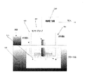
限定されない例として、光学センサ90を耐久性のある高分子化合物のハウジングに一体化し、続いて、原理を証明するために位相蛍光検出(phase fluorometric detection)を用いた溶存酸素(dissolved oxygen;DO)の検出に適用した(図3)。プローブ90を、ガスフロー接続部を一体化したイオン消失水のフロー・セル92に浸漬した。ガスをガス流入口94から流入させ、ガス流出口96から流出させた。質量流量コントローラ(mass flow controller;MFC)を介し、酸素濃度を変化させながら発泡させた。実験の継続期間、フロー・セル92を20℃の一定作動温度に維持された水槽中に沈めた。制御電子回路100を用い、実験を制御した。カスタマイズした(custom-written)LabVIEW VI(英国、National Instruments商標)を用いて、信号を取得および処理した。
As a non-limiting example, an optical sensor 90 is integrated into a durable polymeric housing, followed by dissolved oxygen (DO) using phase fluorometric detection to prove the principle. (Fig. 3). The probe 90 was immersed in a flow cell 92 of ion-dissipating water with an integrated gas flow connection. Gas was introduced from the gas inlet 94 and out of the gas outlet 96. Foaming was performed while changing the oxygen concentration via a mass flow controller (MFC). For the duration of the experiment, the flow cell 92 was submerged in a water bath maintained at a constant operating temperature of 20 °
検出物質は、蛍光ルテニウム錯体[Ru(II)-tris(4,7-diphenyl-1,10-phenanthroline)] (Ru(dpp)3 2+)を含むn-propyltriethoxysilane(PTEOS)先駆物質をベースとした公知のゾル・ゲル薄膜である。膜の配合物は、染料[Ru(dpp)3 2+を[Ru(dpp)3 2+]/PTEOS=1.4×10−3のモル比で伴う、1モルのPTEOS/4 H2O/6.25 EtOH/7.2×10−3 HClを含み;// EtOH中に[Ru(dpp)3 2+]を溶解させ;該錯体が溶解するまで撹拌し;撹拌しながらPTEOSを添加し;および撹拌しながら、HCl(pH1)をゆっくりと滴下する。使用前、その溶液を、少なくとも3週間にわたって撹拌したままにする。 The detection substance is based on an n-propyltriethoxysilane (PTEOS) precursor containing a fluorescent ruthenium complex [Ru (II) -tris (4,7-diphenyl-1,10-phenanthroline)] (Ru (dpp) 3 2+ ). It is a known sol-gel thin film. The formulation of the membrane is 1 mole PTEOS / 4H 2 O / 6 with the dye [Ru (dpp) 3 2+ in a molar ratio of [Ru (dpp) 3 2+ ] /PTEOS=1.4×10 −3. .25 EtOH / 7.2 × 10 −3 with HCl; // dissolve [Ru (dpp) 3 2+ ] in EtOH; stir until the complex is dissolved; add PTEOS with stirring; and While stirring, HCl (pH 1) is slowly added dropwise. Prior to use, the solution is left stirring for at least 3 weeks.
図4は溶存酸素(DO)濃度の機能に対するプローブの応答を、図5は対応するキャリブレーション曲線を示す。検出の限界(limit of detection;LOD)は、0.6秒の積算時間(integration time)で1.5ppb未満に定めた。LODは、YSIから市販されている電気化学的溶存酸素センサ(例えば、YSI 550A Dissolved Oxygen Meter(最小解像度0.01mg/Lないし10ppb)という製品名のYSI製品)と好ましく比較される。 FIG. 4 shows the response of the probe to the function of dissolved oxygen (DO) concentration, and FIG. 5 shows the corresponding calibration curve. The limit of detection (LOD) was set to less than 1.5 ppb with an integration time of 0.6 seconds. The LOD is preferably compared to an electrochemically dissolved oxygen sensor commercially available from YSI (eg, YSI product with a product name of YSI 550A Dissolved Oxygen Meter (minimum resolution 0.01 mg / L to 10 ppb)).
本開示において、図6はDNAハイブリッド形成(DNA hybridization)のリアルタイム検出を表すグラフを示している。図6は、図2に示したようなプローブが取り付けられた光子計数光電子増倍管により記録された2つの曲線を示す。発光信号は、一方の曲線については大きく増加しているが、他方については比較的変化がないままとなっている。前者は、蛍光インジケータCysのラベルが付された単一ストランドのDNA(single stranded DNA)の20mer整合(20mer match)サンプルに対するセンサの応答を表す。各データポイントは500msの期間を超えてPMTにより記録された光子の数に対応している。20mer整合サンプルの導入に応じた信号の著しい増加は、センササンプルの表面上の受容体DNAに対するサンプルDNAの結合を示している。第2の曲線は表面での結合が生じなかったことを示し、これは不適合のサンプルの場合に予測されたものである。これらのデータは、バイオセンシングの用途に対し、光学プローブの能力が表面結合のリアルタイム測定を提供することを示している。 In the present disclosure, FIG. 6 shows a graph representing real-time detection of DNA hybridization. FIG. 6 shows two curves recorded by a photon counting photomultiplier tube fitted with a probe as shown in FIG. The emission signal is greatly increased for one curve but remains relatively unchanged for the other. The former represents the response of the sensor to a 20mer match sample of single stranded DNA labeled with the fluorescent indicator Cys. Each data point corresponds to the number of photons recorded by the PMT over a 500 ms period. A significant increase in signal in response to the introduction of a 20mer matched sample indicates binding of sample DNA to receptor DNA on the surface of the sensor sample. The second curve shows that no binding at the surface occurred, which is expected for a non-conforming sample. These data show that for biosensing applications, the ability of the optical probe provides a real-time measurement of surface binding.
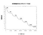
図7は呼吸気分析用の携帯型デバイス110を示す。エアウェイアダプタ114が光学プローブ112に接続されている。この応用例では、図3に示されたセンサキャップ14の代わりにエアウェイアダプタが用いられている。プローブ120はハウジング122に囲繞されたものとすることができる。エアウェイアダプタ114によって、ユーザの息が光学検出プローブ120の検出エレメント118と相互作用可能となる。携帯型デバイス110は、電源、PC、PDAまたはその他のデバイスと接続可能に構成され、情報の収集および処理の補助とすることができる。本開示に係るプローブがユーザの呼吸をモニタリングするマスクに組み込まれていてもよいことも予期できる。デバイスはまた、ユーザにとっての可搬性を向上するためにワイヤレスであってもよい。
FIG. 7 shows a portable device 110 for respiratory analysis. An airway adapter 114 is connected to the
図8はヒトの呼吸気中の酸素のリアルタイム検出を示す。データは、安静時に被験者がエアウェイアダプタ114中に息を吹き込むことによって得られたものであり、1分間当たりほぼ10回の呼吸を行った呼吸速度に対応している。酸素感受性のあるゾル・ゲル物質を前述したように検出エレメントに付与し、被験者にエアウェイアダプタ114中に息を吹き込ませながら、この物質の蛍光発光をリアルタイムで記録した。図8はセンサによって記録された呼吸気中の酸素濃度をリアルタイム展開したものである。適切な検出物質を与えることで、システムは、二酸化炭素、アンモニアおよび麻酔ガスなどを含め呼吸気中に含まれる広範な分析対象の検出を行うのに互換性のあるものとされる。 FIG. 8 shows real-time detection of oxygen in human respiratory air. The data was obtained when the subject breathed into the airway adapter 114 at rest, and corresponds to the breathing rate at which approximately 10 breaths per minute were taken. An oxygen-sensitive sol-gel material was applied to the detection element as described above, and the fluorescence emission of this material was recorded in real time as the subject was breathing into the airway adapter 114. FIG. 8 is a real-time development of the oxygen concentration in the respiratory air recorded by the sensor. By providing appropriate detection materials, the system is compatible with the detection of a wide range of analytes contained in respiratory air, including carbon dioxide, ammonia and anesthetic gases.
ここに開示した実施形態に対し様々な変形が可能であることは理解されよう。よって、上述の記載は限定的なものとして解釈されるべきではなく、様々な実施形態の単なる例示として解釈されるべきである。当業者であれば、添付の請求の範囲の精神および範囲内で他の変形を想起できるであろう。 It will be understood that various modifications may be made to the embodiments disclosed herein. Therefore, the above description should not be construed as limiting, but merely as exemplifications of various embodiments. Those skilled in the art will envision other modifications within the scope and spirit of the claims appended hereto.
Claims (10)
パラボラ状の光導波路と、
取り外し可能な要素を有し、前記光導波路を保持するよう構成された外側ハウジングと、
該外側ハウジングと前記取り外し可能な要素との間にあって前記導波路を所定位置に保持するよう構成された導波路マウントと、
少なくとも1つの分析対象の検出を行うための検出物質と、
該検出物質を励起するよう構成された励起源と、
放射光の通過を許容するよう構成された放射フィルタと、
放射光を光検出器上に集束させる捕集光学系と、
該捕集光学系を通過した放射光を検出する測定用の光検出器と、
を具えたことを特徴とする光学プローブ。 An optical probe for detecting light emitted by a sample,
A parabolic optical waveguide;
An outer housing having a removable element and configured to hold the optical waveguide;
A waveguide mount between the outer housing and the removable element configured to hold the waveguide in place;
A detection substance for detecting at least one analyte;
An excitation source configured to excite the detection material;
A radiation filter configured to allow passage of radiation; and
A collection optics that focuses the emitted light onto a photodetector;
A photodetector for measurement that detects the radiated light that has passed through the collection optical system;
An optical probe characterized by comprising:
パラボラ状の光導波路と、
取り外し可能な要素を有し、前記光導波路を保持するよう構成された外側ハウジングと、
少なくとも1つの分析対象の検出を行うための検出物質と、
該検出物質を励起するよう構成された励起源と、
前記放射光を検出する測定用の光検出器と、
を具えたことを特徴とする光学プローブ。 An optical probe for detecting light emitted by a sample,
A parabolic optical waveguide;
An outer housing having a removable element and configured to hold the optical waveguide;
A detection substance for detecting at least one analyte;
An excitation source configured to excite the detection material;
A measurement photodetector for detecting the emitted light;
An optical probe characterized by comprising:
パラボラ状の光導波路と、
取り外し可能な要素を有し、前記光導波路を保持するよう構成された外側ハウジングと、
少なくとも1つの分析対象の検出を行うための検出物質と、
該検出物質を励起するよう構成された励起源と、
前記放射光を検出する測定用の光検出器と、
前記光学プローブに作動的に接続され、ユーザの息を分析するためのエアウェイアダプタと、
を具えたことを特徴とする光学プローブ。 An optical probe for detecting light emitted by a sample,
A parabolic optical waveguide;
An outer housing having a removable element and configured to hold the optical waveguide;
A detection substance for detecting at least one analyte;
An excitation source configured to excite the detection material;
A measurement photodetector for detecting the emitted light;
An airway adapter operatively connected to the optical probe for analyzing a user's breath;
An optical probe characterized by comprising:
Applications Claiming Priority (2)
| Application Number | Priority Date | Filing Date | Title |
|---|---|---|---|
| US79842306P | 2006-05-05 | 2006-05-05 | |
| PCT/IB2007/003920 WO2008029298A2 (en) | 2006-05-05 | 2007-05-07 | Optical probe |
Publications (2)
| Publication Number | Publication Date |
|---|---|
| JP2009536339A true JP2009536339A (en) | 2009-10-08 |
| JP2009536339A5 JP2009536339A5 (en) | 2010-07-01 |
Family
ID=39157642
Family Applications (1)
| Application Number | Title | Priority Date | Filing Date |
|---|---|---|---|
| JP2009508548A Pending JP2009536339A (en) | 2006-05-05 | 2007-05-07 | Optical probe |
Country Status (5)
| Country | Link |
|---|---|
| US (1) | US8163241B2 (en) |
| EP (1) | EP2016393A2 (en) |
| JP (1) | JP2009536339A (en) |
| CN (1) | CN101438145A (en) |
| WO (1) | WO2008029298A2 (en) |
Families Citing this family (11)
| Publication number | Priority date | Publication date | Assignee | Title |
|---|---|---|---|---|
| DE102007020610A1 (en) * | 2007-04-30 | 2008-11-20 | Thomas Dr. Ruckstuhl | Container and method for detecting fluorescence |
| GB2480293A (en) * | 2010-05-12 | 2011-11-16 | Univ Dublin City | A luminescence based sensor |
| FR2966937B1 (en) * | 2010-10-28 | 2012-12-28 | Univ Paris Diderot Paris 7 | METHOD FOR OBSERVING THE LIGHT EMISSION OF A SAMPLE BY DYNAMIC OPTICAL MICROSCOPY |
| US8945936B2 (en) | 2011-04-06 | 2015-02-03 | Fresenius Medical Care Holdings, Inc. | Measuring chemical properties of a sample fluid in dialysis systems |
| DE102011081326A1 (en) * | 2011-08-22 | 2013-02-28 | Endress + Hauser Conducta Gesellschaft für Mess- und Regeltechnik mbH + Co. KG | Optical sensor for determining concentration of aqueous solution e.g. drinking water, has optical receiver which transmits electric signal to sensor elements for evaluating light characteristics |
| AT512498B1 (en) * | 2012-06-06 | 2013-09-15 | Joanneum Res Forschungsgmbh | Opto-chemical sensor |
| CN103197451B (en) * | 2013-04-12 | 2015-09-09 | 苏州华兴源创电子科技有限公司 | A kind of optic probe and comprise the equipment for measuring liquid crystal module Flicker flicker degree of this probe |
| US11199498B2 (en) | 2013-05-09 | 2021-12-14 | University Of Central Florida Research Foundation, Inc. | Portable spectrometer for the presumptive identification of substances |
| WO2014183026A1 (en) * | 2013-05-09 | 2014-11-13 | University Of Central Florida Research Foundation, Inc. | A portable spectrometer for the presumptive identification of illicit drugs and substances of abuse |
| IT201700030049A1 (en) * | 2017-03-17 | 2018-09-17 | Open Fields S R L | Mobile detection device, relative system and procedure for the detection and monitoring of chemical-physical parameters inside a container for storage and / or transport of solid material |
| DE102017223851B4 (en) * | 2017-12-28 | 2020-08-06 | Biochip Systems GmbH | Sensor arrangement for the detection of at least one material property of a sample and microtiter plate with a plurality of sensor arrangements |
Citations (1)
| Publication number | Priority date | Publication date | Assignee | Title |
|---|---|---|---|---|
| WO2002090948A1 (en) * | 2001-05-03 | 2002-11-14 | Delta Dansk Elektronik, Lys & Akustik | Apparatus and sensing devices for measuring fluorescence lifetimes of fluorescence sensors |
Family Cites Families (8)
| Publication number | Priority date | Publication date | Assignee | Title |
|---|---|---|---|---|
| US3838277A (en) * | 1972-06-28 | 1974-09-24 | Org Europ De Rech Spatiales | Optical sensor with linear parabolic mirror |
| AT393565B (en) * | 1988-08-09 | 1991-11-11 | Avl Verbrennungskraft Messtech | DISPOSABLE MEASURING ELEMENT |
| DE19810615A1 (en) | 1998-03-12 | 1999-09-16 | Thomas Ruckstuhl | High efficiency optical system detecting light from e.g. excited marked biomolecules |
| US7416703B2 (en) * | 1998-04-28 | 2008-08-26 | The Johns Hopkins University | Polymer based lanthanide luminescent sensors for the detection of organophosphorus compounds |
| US6632402B2 (en) | 2001-01-24 | 2003-10-14 | Ntc Technology Inc. | Oxygen monitoring apparatus |
| US6694158B2 (en) * | 2001-04-11 | 2004-02-17 | Motorola, Inc. | System using a portable detection device for detection of an analyte through body tissue |
| US7183552B2 (en) * | 2003-03-07 | 2007-02-27 | Ric Investments, Llc | Optical system for a gas measurement system |
| JP4480130B2 (en) * | 2003-12-16 | 2010-06-16 | キヤノン株式会社 | Optical analyzer |
-
2007
- 2007-05-07 US US12/299,666 patent/US8163241B2/en not_active Expired - Fee Related
- 2007-05-07 JP JP2009508548A patent/JP2009536339A/en active Pending
- 2007-05-07 WO PCT/IB2007/003920 patent/WO2008029298A2/en active Application Filing
- 2007-05-07 CN CNA2007800162767A patent/CN101438145A/en active Pending
- 2007-05-07 EP EP07849024A patent/EP2016393A2/en not_active Withdrawn
Patent Citations (1)
| Publication number | Priority date | Publication date | Assignee | Title |
|---|---|---|---|---|
| WO2002090948A1 (en) * | 2001-05-03 | 2002-11-14 | Delta Dansk Elektronik, Lys & Akustik | Apparatus and sensing devices for measuring fluorescence lifetimes of fluorescence sensors |
Also Published As
| Publication number | Publication date |
|---|---|
| US8163241B2 (en) | 2012-04-24 |
| WO2008029298A3 (en) | 2008-06-26 |
| US20090191092A1 (en) | 2009-07-30 |
| WO2008029298A2 (en) | 2008-03-13 |
| EP2016393A2 (en) | 2009-01-21 |
| CN101438145A (en) | 2009-05-20 |
Similar Documents
| Publication | Publication Date | Title |
|---|---|---|
| US8163241B2 (en) | Optical probe | |
| Wencel et al. | Optical chemical pH sensors | |
| JP4933271B2 (en) | Handheld device with a disposable element for chemical analysis of multiple specimens | |
| JP3764482B2 (en) | Simultaneous double excitation / single emission fluorescence sensing method for pH and pCO 2 | |
| US8625100B2 (en) | Method for the optical determining of a measured variable of a medium | |
| Burke et al. | Development of an optical sensor probe for the detection of dissolved carbon dioxide | |
| US20100167412A1 (en) | Sensor system for determining concentration of chemical and biological analytes | |
| JP4640797B2 (en) | Biomolecular interaction measuring apparatus and measuring method | |
| Klimant et al. | Dual lifetime referencing (DLR)—a new scheme for converting fluorescence intensity into a frequency-domain or time-domain information | |
| JP2009536339A5 (en) | ||
| EP2635624B1 (en) | Optical sensor and sensing system for oxygen monitoring in fluids using molybdenum cluster phosphorescence | |
| Werner et al. | Fiber optic sensor designs and luminescence-based methods for the detection of oxygen and pH measurement | |
| KR101705602B1 (en) | Optical sensor for fluorescence detection based on a smartphone camera | |
| Clarke et al. | Characterisation and deployment of an immobilised pH sensor spot towards surface ocean pH measurements | |
| CN111491735A (en) | Mobile biosensing instrument with multiple detection forms | |
| Deepa et al. | Sol–gel based portable optical sensor for simultaneous and minimal invasive measurement of pH and dissolved oxygen | |
| US6241948B1 (en) | Sensing device with sol-gel derived film on the light source | |
| Borisov et al. | Modified dual lifetime referencing method for simultaneous optical determination and sensing of two analytes | |
| Narayanaswamy | Optical chemical sensors and biosensors for food safety and security applications | |
| US20100163748A1 (en) | Dual detector capillary waveguide biosensor and method for use thereof | |
| JP2006275817A (en) | Method and device for detecting formaldehyde | |
| EP1455176A2 (en) | Integrated photodetector for heavy metals and biological activity analysis | |
| CN101393202A (en) | Evanescent wave optical fiber biosensor and use thereof | |
| Gorbunova et al. | A monitor calibrator as a portable tool for determination of luminescent compounds | |
| JP2986712B2 (en) | Chemical sensor, apparatus and method for measuring chloride ion concentration using the same |
Legal Events
| Date | Code | Title | Description |
|---|---|---|---|
| A521 | Written amendment |
Free format text: JAPANESE INTERMEDIATE CODE: A523 Effective date: 20100507 |
|
| A621 | Written request for application examination |
Free format text: JAPANESE INTERMEDIATE CODE: A621 Effective date: 20100507 |
|
| A977 | Report on retrieval |
Free format text: JAPANESE INTERMEDIATE CODE: A971007 Effective date: 20120302 |
|
| A131 | Notification of reasons for refusal |
Free format text: JAPANESE INTERMEDIATE CODE: A131 Effective date: 20120309 |
|
| A02 | Decision of refusal |
Free format text: JAPANESE INTERMEDIATE CODE: A02 Effective date: 20120803 |