JP2009532745A - Seating with floating composite image - Google Patents
Seating with floating composite image Download PDFInfo
- Publication number
- JP2009532745A JP2009532745A JP2009504399A JP2009504399A JP2009532745A JP 2009532745 A JP2009532745 A JP 2009532745A JP 2009504399 A JP2009504399 A JP 2009504399A JP 2009504399 A JP2009504399 A JP 2009504399A JP 2009532745 A JP2009532745 A JP 2009532745A
- Authority
- JP
- Japan
- Prior art keywords
- sheeting
- layer
- microlenses
- image
- images
- Prior art date
- Legal status (The legal status is an assumption and is not a legal conclusion. Google has not performed a legal analysis and makes no representation as to the accuracy of the status listed.)
- Pending
Links
Images


Classifications
-
- G—PHYSICS
- G02—OPTICS
- G02B—OPTICAL ELEMENTS, SYSTEMS OR APPARATUS
- G02B5/00—Optical elements other than lenses
- G02B5/12—Reflex reflectors
- G02B5/126—Reflex reflectors including curved refracting surface
- G02B5/128—Reflex reflectors including curved refracting surface transparent spheres being embedded in matrix
-
- B—PERFORMING OPERATIONS; TRANSPORTING
- B44—DECORATIVE ARTS
- B44F—SPECIAL DESIGNS OR PICTURES
- B44F1/00—Designs or pictures characterised by special or unusual light effects
- B44F1/08—Designs or pictures characterised by special or unusual light effects characterised by colour effects
- B44F1/10—Changing, amusing, or secret pictures
-
- G—PHYSICS
- G02—OPTICS
- G02B—OPTICAL ELEMENTS, SYSTEMS OR APPARATUS
- G02B3/00—Simple or compound lenses
- G02B3/0006—Arrays
-
- G—PHYSICS
- G02—OPTICS
- G02B—OPTICAL ELEMENTS, SYSTEMS OR APPARATUS
- G02B30/00—Optical systems or apparatus for producing three-dimensional [3D] effects, e.g. stereoscopic images
- G02B30/20—Optical systems or apparatus for producing three-dimensional [3D] effects, e.g. stereoscopic images by providing first and second parallax images to an observer's left and right eyes
- G02B30/26—Optical systems or apparatus for producing three-dimensional [3D] effects, e.g. stereoscopic images by providing first and second parallax images to an observer's left and right eyes of the autostereoscopic type
- G02B30/27—Optical systems or apparatus for producing three-dimensional [3D] effects, e.g. stereoscopic images by providing first and second parallax images to an observer's left and right eyes of the autostereoscopic type involving lenticular arrays
-
- G—PHYSICS
- G02—OPTICS
- G02B—OPTICAL ELEMENTS, SYSTEMS OR APPARATUS
- G02B30/00—Optical systems or apparatus for producing three-dimensional [3D] effects, e.g. stereoscopic images
- G02B30/50—Optical systems or apparatus for producing three-dimensional [3D] effects, e.g. stereoscopic images the image being built up from image elements distributed over a 3D volume, e.g. voxels
- G02B30/56—Optical systems or apparatus for producing three-dimensional [3D] effects, e.g. stereoscopic images the image being built up from image elements distributed over a 3D volume, e.g. voxels by projecting aerial or floating images
Abstract
合成画像を有する半透明、透明、又は準半透明の(semi-translucent)マイクロレンズシーティングが開示され、その中で合成画像は、シーティングの上方若しくは下方、又は両方に浮動する。合成画像は二次元である場合も、又は三次元である場合もある。シーティングは、材料の層の内部の複数の位置に1以上の画像を形成する複数のマイクロレンズの表面を有する少なくとも1つの材料の層を有する場合があり、複数の画像の少なくとも1つは、部分的に完全な画像である。再帰反射、半透明、透明、又は光学構造の層などの追加の層もまたシーティングの中に組み込まれる場合がある。 A translucent, transparent, or semi-translucent microlens sheeting with a composite image is disclosed, in which the composite image floats above or below the sheeting, or both. The composite image may be two-dimensional or three-dimensional. The sheeting may have at least one layer of material having a plurality of microlens surfaces forming one or more images at a plurality of locations within the layer of material, wherein at least one of the plurality of images is a partial Complete image. Additional layers such as retroreflective, translucent, transparent, or optical structures may also be incorporated into the sheeting.
Description
本発明は、シーティングに対して間隙を介して浮遊していると観測者に知覚される1以上の合成画像を提供するシーティングに関し、その中で合成画像の見え方は視角と共に変化する。 The present invention relates to a sheeting that provides one or more composite images that are perceived by an observer as floating with respect to the sheeting, in which the appearance of the composite image varies with viewing angle.
グラフィック画像又は他のしるしを有するシーティング材料は、特に物品又は文書を認証するためのラベルとして、広く使用されてきた。例えば、米国特許第3,154,872号;同3,801,183号;同4,082,426号;及び第4,099,838号に記載されたもののようなシーティングは、車両のライセンスプレートのための認証ステッカーとして、及び運転免許証、政府文書、カセットテープ、トランプ、飲料容器などのためのセキュリティーフィルムとして使用されてきた。他の使用には、警察、消防、又はその他の緊急車両に対して、広告及び販売促進ディスプレイにおいて、並びにブランド強化を提供するための独特のラベルとしてなど、識別目的のためのグラフィックス用途が挙げられる。 Sheeting materials with graphic images or other indicia have been widely used, especially as labels for authenticating articles or documents. For example, seating such as those described in U.S. Pat. Nos. 3,154,872; 3,801,183; 4,082,426; and 4,099,838 can be applied to vehicle license plates. It has been used as an authentication sticker for and as a security film for driver's licenses, government documents, cassette tapes, playing cards, beverage containers and the like. Other uses include graphics applications for identification purposes, such as for police, firefighting or other emergency vehicles, in advertising and promotional displays, and as a unique label to provide brand enhancement. It is done.
画像化されたシーティングの別の形態は、米国特許第4,200,875号(ガラノス(Galanos))に開示されている。ガラノス(Galanos)は、特に「露出レンズ型の高利得再帰反射シーティング(high-gain retroreflective sheeting of the exposed-lens type)」の使用を開示し、その中で複数の画像は、マスク又はパターンを通したシーティングのレーザー照射により形成される。そのシーティングは、結合剤層の中に部分的に埋め込まれるとともに結合剤層の上方に部分的に露出された複数個の透明なガラス微小球を、複数個の微小球の各々の埋め込まれた表面上にコーティングされた金属反射層と共に含む。結合剤層はカーボンブラックを含有し、これは、シーティングが画像化されている間にシーティングに衝突するいずれかの迷光を最小化すると言われている。レーザービームのエネルギーは、結合剤層の中に埋め込まれた複数のマイクロレンズの集束効果により更に濃縮される。 Another form of imaged sheeting is disclosed in US Pat. No. 4,200,875 (Galanos). Galanos specifically discloses the use of “high-gain retroreflective sheeting of the exposed-lens type”, in which multiple images pass through a mask or pattern. It is formed by laser irradiation of the sheeting. The sheeting includes a plurality of transparent glass microspheres partially embedded in the binder layer and partially exposed above the binder layer, each embedded surface of the plurality of microspheres. With metal reflective layer coated on top. The binder layer contains carbon black, which is said to minimize any stray light that impinges on the sheeting while the sheeting is imaged. The energy of the laser beam is further concentrated by the focusing effect of a plurality of microlenses embedded in the binder layer.
ガラノス(Galanos)の再帰反射シーティングの中に形成された複数の画像は、レーザー照射がシーティングに向けられた角度と同じ角度からシーティングを見る場合、及びその場合にのみ見ることができる。それは、言葉を変えると、非常に限られた観測角の間でだけ画像が見えることを意味する。そのためまた他の理由により、こうしたシーティングの特定の性質の改善が望まれてきた。 The plurality of images formed in Galanos retroreflective sheeting can and are only seen when viewing the sheeting from the same angle that the laser illumination was directed to the sheeting. In other words, it means that the image can only be seen between very limited observation angles. Therefore, for other reasons, it has been desirable to improve the specific nature of such sheeting.
早くも1908年に、ガブリエル・リップマン(Gabriel Lippman)は、1以上の感光層を有するレンチキュラー媒体中に、シーンの真の三次元画像を生成するための方法を発明した。そのプロセスは、インテグラルフォトグラフィとして既知であるが、デ・モンテベロ(De Montebello)[1984]「三次元データの加工及び表示II(Processing and Display of Three-Dimensional Data II)」(「写真光学計測技術者協会会報(Proceedings of SPIE)」、サンディエゴ(San Diego))にもまた記載されている。リップマン(Lippman)の方法では、写真乾板がレンズ(又は「レンズレット」)のアレイを通して暴露され、その結果アレイの各レンズレットは、再生されているシーンのミニチュア画像を、そのレンズレットによって占有されたシートの視点から見えるように写真乾板上の感光層に透過する。写真乾板が現像された後、レンズレットアレイを通して乾板上の合成画像を眺める観測者は、撮影されたシーンの三次元表現を見る。画像は、使用された感光材料に依存して、白黒であっても又はカラーであってもよい。 As early as 1908, Gabriel Lippman invented a method for generating a true three-dimensional image of a scene in a lenticular medium having one or more photosensitive layers. The process is known as integral photography, but De Montebello [1984] “Processing and Display of Three-Dimensional Data II” (“Photometric Measurements”). It is also described in the Proceedings of SPIE (San Diego). In Lippman's method, a photographic plate is exposed through an array of lenses (or “lenslets”) so that each lenslet in the array occupies a miniature image of the scene being played by the lenslet. It passes through the photosensitive layer on the photographic plate so that it can be seen from the point of view of the sheet. After the photographic plate is developed, an observer viewing a composite image on the plate through a lenslet array sees a three-dimensional representation of the photographed scene. The image may be black and white or color depending on the photosensitive material used.
乾板の暴露中にレンズレットにより形成された画像は、各ミニチュア画像の1回の反転のみを経験しているため、生成された三次元表現は疑視像である。即ち、画像の知覚された深さは反転され、その結果オブジェクトは、「裏返し」に見える。画像を修正するためには、2つの光学反転(optical inversion)を実現する必要があるため、これは重大な不利点である。これらの方法は複雑であり、同一オブジェクトの複数個の見え方を記録するために、単一カメラ、又は複数のカメラ、又はマルチレンズカメラによる複数の暴露を伴い、また、単一の三次元画像を提供するために複数の画像の極めて精度の高いレジストレーションを必要とする。更に、従来のカメラに頼るいずれの方法も、カメラの前に実オブジェクトの存在を必要とする。これは更にその方法を、仮想オブジェクト(効果上存在するが、現実には存在しないオブジェクトを意味する)の三次元画像を生成するためには不適合にする。インテグラルフォトグラフィの更なる不利点は、見られうる実像を形成するためには、合成画像は見る側から光に照らされなければならないということである。 Since the image formed by the lenslet during the exposure of the plate experiences only one inversion of each miniature image, the generated three-dimensional representation is a suspicious image. That is, the perceived depth of the image is reversed, so that the object looks “inside out”. This is a serious disadvantage because it requires two optical inversions to be corrected to correct the image. These methods are complex and involve multiple exposures by a single camera, or multiple cameras, or multi-lens cameras to record multiple views of the same object, and a single 3D image To provide a highly accurate registration of multiple images. Furthermore, any method that relies on a conventional camera requires the presence of a real object in front of the camera. This further makes the method incompatible for generating a three-dimensional image of a virtual object (meaning an object that exists in effect but does not actually exist). A further disadvantage of integral photography is that the composite image must be illuminated from the viewer side to form a real image that can be seen.
本発明は、シーティングの上方又は下方に浮遊しているように見える合成画像を有するマイクロレンズシーティングを提供する。これらの浮遊した複数の画像は、便宜のため浮動画像と呼ばれ、それらは、シーティングの上方若しくはシーティングの下方に位置することができるか(二次元又は三次元画像のいずれかとして)、又は、シーティングの上方、シーティングの平面内及びシーティングの下方に見える三次元画像であることができる。画像は、白黒であることも又はカラーであることもでき、及び観測者と共に移動するように見える。浮動画像は、観測者によって肉眼で観測されることができる。 The present invention provides a microlens sheeting having a composite image that appears to float above or below the sheeting. These floating images are referred to as floating images for convenience and can they be located above the sheeting or below the sheeting (as either 2D or 3D images), or It can be a three-dimensional image visible above the sheeting, in the plane of the sheeting and below the sheeting. The image can be black and white or color and appears to move with the observer. The floating image can be observed with the naked eye by an observer.
マイクロレンズシーティングの浮動画像は、材料の隣接層を必要とせずに、マイクロレンズを備えた材料の層内に形成されてもよい。複数のマイクロレンズの形状、及び複数のマイクロレンズがその上に形成される材料の層の厚さは、アレイに入射する視準光が、シーティングの層内の領域に集束するように選択される。マイクロレンズシーティングに衝突する入射光のエネルギーが、複数のマイクロレンズ各々によってシーティング内の領域に集束される。この集束されたエネルギーは層を変性して画像を提供し、そのサイズ、形状、及び外観は、光線と複数のマイクロレンズとの間の相互作用に依存する。例えば、光線は、光分解、炭化(charring)、又はシーティングへの他の損傷の結果としての損傷部分において、層内の複数のマイクロレンズの各々に関連した画像を形成してもよい。 The floating image of the microlens sheeting may be formed in a layer of material with microlenses without the need for an adjacent layer of material. The shape of the plurality of microlenses and the thickness of the layer of material on which the plurality of microlenses are formed are selected such that collimated light incident on the array is focused onto a region in the sheeting layer. . The energy of incident light impinging on the microlens sheeting is focused on a region in the sheeting by each of the plurality of microlenses. This focused energy modifies the layer to provide an image whose size, shape and appearance depend on the interaction between the light beam and the plurality of microlenses. For example, the light beam may form an image associated with each of the plurality of microlenses in the layer in the damaged portion as a result of photolysis, charring, or other damage to the sheeting.
記載されたような合成画像を有する本発明のシーティングは、セキュリティー文書、パスポート、身分証明書、金融取引カード(例えば、クレジットカード)、ライセンスプレート、などの物品中の不正開封防止画像を確実なものにするなど多様な用途において使用されてもよい。 The seating of the present invention with a composite image as described ensures a tamper-proof image in an article such as a security document, passport, identification card, financial transaction card (eg, credit card), license plate, etc. It may be used in various applications such as.
1つの実施形態では、シーティングは、材料の層の内部の複数の位置に1以上の画像を形成する複数のマイクロレンズの表面を有する材料の層を含み、複数の画像の少なくとも1つは部分的に完成した画像であり、複数の画像の各々は複数のマイクロレンズの異なる1つと関連しており、複数のマイクロレンズは、材料の層内の複数の位置に光を透過して材料の層内に形成された複数の画像から合成画像を生成する屈折面を有し、合成画像は、シーティングの上方に浮動するか、シーティングの下方に浮動するか、又はシーティングの面内に浮動するように見える。 In one embodiment, the sheeting includes a layer of material having a plurality of microlens surfaces forming one or more images at a plurality of locations within the layer of material, wherein at least one of the plurality of images is partially And each of the plurality of images is associated with a different one of the plurality of microlenses, the plurality of microlenses transmitting light to a plurality of positions in the layer of material and within the layer of material. A refracting surface that generates a composite image from a plurality of images formed on the surface, the composite image floating above the sheeting, floating below the sheeting, or floating within the surface of the sheeting .
別の実施形態では、シーティングは、第1面上に形成された複数のマイクロレンズと、複数のマイクロレンズの反対側の第2面上に形成された再帰反射の部分と、を有する材料の単層を含み、この材料の層は、複数のマイクロレンズと再帰反射の部分との間に形成された1以上の画像を包含し、この複数のマイクロレンズは、シーティングの上方に浮動するか、シーティングの下方に浮動するか、又はシーティングの平面内に浮動するように見える合成画像を生成する。 In another embodiment, the sheeting is a single piece of material having a plurality of microlenses formed on the first surface and a portion of retroreflection formed on the second surface opposite the plurality of microlenses. The layer of material includes one or more images formed between the plurality of microlenses and the retroreflective portion, the plurality of microlenses floating above the sheeting or the sheeting Or a composite image that appears to float in the plane of the sheeting.
更なる実施形態では、シーティングは、複数のマイクロレンズの表面を有する材料の層と、再帰反射の層と、材料の層及び再帰反射の層との間に配置された放射線感応層と、を含み、放射線感応層は、材料の層と再帰反射の部分との間に形成された1以上の画像を包含し、複数のマイクロレンズは放射線感応層の複数の画像から、シーティングの上方に浮動するか、シーティングの下方に浮動するか、又はシーティングの面内浮動するように見える合成画像を生成する。 In a further embodiment, the sheeting includes a layer of material having a plurality of microlens surfaces, a retroreflective layer, and a radiation sensitive layer disposed between the material layer and the retroreflective layer. The radiation sensitive layer includes one or more images formed between the layer of material and the retroreflective portion, and the plurality of microlenses float from the plurality of images of the radiation sensitive layer above the sheeting. Generate a composite image that appears to float below the sheeting or float in-plane of the sheeting.
更に別の実施形態では、第1及び第2面を有するシーティングは、複数のマイクロレンズの表面を有する材料の第1層と、第1層に近接して配置された複数のマイクロレンズの表面を有する材料の第2層と、を含み、1以上の画像が、第1層の複数のマイクロレンズと第2層の複数のマイクロレンズとの間の場所にあるシーティング内に形成され、画像の少なくとも1つは部分的に完成した画像であり、各画像は第1層の複数個のマイクロレンズの1つと関連しており、複数のマイクロレンズは、シーティング内の位置に光を透過してシーティングの上方に浮動するか、シーティングの下方に浮動するか、又はシーティングの平面内に浮動するように見える合成画像を複数の画像から生成する屈折面を有し、合成画像がシーティングの第1面及び第2面の両方から見えるように、第1層の複数のマイクロレンズ及び第2層の複数のマイクロレンズは位置合わせされる。 In yet another embodiment, the sheeting having the first and second surfaces comprises a first layer of material having a plurality of microlens surfaces and a plurality of microlens surfaces disposed proximate to the first layer. A second layer of material having one or more images formed in a sheet at a location between the plurality of microlenses of the first layer and the plurality of microlenses of the second layer, wherein at least one of the images One is a partially completed image, and each image is associated with one of a plurality of microlenses in the first layer, the plurality of microlenses transmitting light to a position within the sheeting and A refracting surface for generating a composite image from the plurality of images that floats upward, floats below the sheeting, or appears to float in the plane of the sheeting, the composite image being the first surface of the sheeting Beauty As seen from both the second surface, a plurality of micro-lenses of the plurality of micro lenses and the second layer of the first layer is aligned.
更に別の実施形態では、シーティングは、第1面上に形成された第1セットの複数のマイクロレンズと、第1セットの複数のマイクロレンズの反対側の第2面上に形成された第2セットの複数のマイクロレンズと、を有する単層を含み、単層は、この単層に対して内部に形成された1以上の画像を包含し、その複数の画像から、第1セットの複数のマイクロレンズ及び第2セットの複数のマイクロレンズは、シーティングの第1面及び第2面の両方から見える合成画像を生成する。 In yet another embodiment, the sheeting is a first set of microlenses formed on the first surface and a second surface formed on the second surface opposite the first set of microlenses. A single layer having a plurality of microlenses in the set, the single layer including one or more images formed therein relative to the single layer, from the plurality of images, the plurality of first set The microlens and the second set of microlenses produce a composite image that is visible from both the first and second surfaces of the sheeting.
本発明の1以上の実施形態の詳細は、添付図面及び以下の説明において記載される。本発明の他の特徴、目的、及び利点は、その説明と図面から、及び特許請求の範囲から明らかになるであろう。 The details of one or more embodiments of the invention are set forth in the accompanying drawings and the description below. Other features, objects, and advantages of the invention will be apparent from the description and drawings, and from the claims.
本発明のマイクロレンズシーティングは、多数のマイクロレンズに関連した複数の画像の個々により提供された、シーティングの上方に、シーティングの面内に、及び/又はシーティングの下方に浮遊するか、又は浮動するように見える合成画像を提供する。 The microlens sheeting of the present invention floats or floats above the sheeting, in the plane of the sheeting, and / or below the sheeting provided by each of a plurality of images associated with multiple microlenses. Provide a composite image that looks like
本発明の完全な説明を提供するために、マイクロレンズシーティングが以下のI部に記載され、その後に、こうしたシーティングの材料層(好ましくは放射線感応材料層)の説明がII部に、放射線源がIII部に、及び画像化プロセスがIV部に続く。本発明の様々な実施形態を更に説明するために、幾つかの実施例もまた提供される。 To provide a complete description of the present invention, microlens sheeting is described in Part I below, followed by a description of the material layer (preferably a radiation sensitive material layer) of such sheeting in Part II and a radiation source. Part III and the imaging process follow Part IV. In order to further illustrate the various embodiments of the present invention, several examples are also provided.
I.マイクロレンズシーティング
本発明の画像がその中で形成され得るマイクロレンズシーティングは、複数のマイクロレンズの1以上の別個の層を、マイクロレンズの層(1又は複数)の片側に隣接して配置された材料の層(以下に記載されるように、好ましくは放射線感応材料又はコーティング)と共に含む。例えば、図1は、典型的には高分子材料である結合剤層14の中に部分的に埋め込まれている透明な微小球12の単層を包含する、マイクロレンズシーティング10の「露出レンズ」の種類を示す。微小球は、材料の層を画像化するために使用されてもよい放射線の波長、及び合成画像がその中で見られる光の波長の両方に対して透明である。材料の層16は、各微小球の裏面のところに配置され、図解された実施形態では、微小球12の各々の表面の一部分だけに典型的には接触する。この種類のシーティングは、米国特許第2,326,634号に非常に詳細に記載されており、現在3Mから表記「スコッチライト8910シリーズ反射布地(Scotchlite 8910 series reflective fabric)」により入手可能である。
I. Microlens Sheeting A microlens sheeting in which an image of the present invention can be formed has one or more separate layers of a plurality of microlenses disposed adjacent to one side of the microlens layer (s). Including a layer of material (preferably a radiation sensitive material or coating, as described below). For example, FIG. 1 shows an “exposed lens” of a
図2は、別の好適な種類のマイクロレンズシーティングを示す。このマイクロレンズシーティング20は、典型的には高分子材料である透明な保護膜24の中に微小球レンズ22が埋め込まれている、シーティングの「埋め込みレンズ」の種類である。材料の層26は、微小球の背後、典型的にはこれもまた高分子材料である透明なスペーサー層28の後ろに配置されている。この種類のシーティングは、米国特許第3,801,183号に非常に詳細に記載されており、現在3Mから表記「スコッチライト3290シリーズエンジニア等級再帰反射シーティング(Scotchlite 3290 series Engineer grade retroreflective sheeting)」により入手可能である。別の好適な種類のマイクロレンズシーティングは、封入レンズシーティングと呼ばれ、その例は、米国特許第5,064,272号に記載され、現在3Mから表記「スコッチライト3870シリーズ高強度等級再帰反射シーティング(Scotchlite 3870 series High Intensity grade retroreflective sheeting)」のもとに入手可能である。
FIG. 2 shows another suitable type of microlens sheeting. The
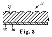
図3は、更に別の好適な種類のマイクロレンズシーティングを示す。このシーティングは、第1及び第2の幅広い面を有する透明な平凸又は非球面ベースシート30を含み、第2面32はほぼ平面であり、第1面はほぼ半球面の又は半非球面(hemi-aspheroidal)の複数のマイクロレンズのアレイ34を有する。複数のマイクロレンズの形状及びベースシートの厚さは、アレイに入射する視準光が、第2面にほぼ集束するように選択される。材料の層36は、第2面上に提供される。この種類のシーティングは、例えば米国特許第5,254,390号に記載されており、現在3Mから表記「2600シリーズ3Mセキュア・カード・レセプター(2600 series 3M Secure Card receptor)」のもとに入手可能である。
FIG. 3 shows yet another suitable type of microlens sheeting. The sheeting includes a transparent plano-convex or
シーティングの複数のマイクロレンズは、画像形成が生じるように、画像形成屈折面を好ましくは有し、一般にこれは湾曲したマイクロレンズ表面により提供される。曲面について、マイクロレンズは好ましくは均一の屈折率を有する。屈折率傾斜(GRIN)を提供する他の有用な材料は、光を屈折させるために曲面を必ずしも必要としない。マイクロレンズ表面は好ましくは本来球面であるが、非球面の表面もまた受け入れることができる。複数のマイクロレンズは、実像が屈折面によって形成されるという複数の条件の下に、円筒又は球などのいずれかの対称性を有してもよい。複数のマイクロレンズ自体は、円形平凸レンズレット、円形両凸レンズレット、ロッド、微小球、ビーズ、又は円筒レンズレットなどの別個の形態であることができる。複数のマイクロレンズが形成されることができる材料には、ガラス、ポリマー、鉱物、結晶、半導体、並びにこれらの及び他の材料の組み合わせが挙げられる。別個でないマイクロレンズ要素もまた使用されてもよい。したがって、複製又はエンボス加工プロセス(この場合、シーティングの表面は形状を変更され、画像化特性を有する繰返しの輪郭を生成する)から形成された複数のマイクロレンズもまた使用されることができる。 The sheeting microlenses preferably have an imaging refractive surface so that imaging occurs, generally this is provided by a curved microlens surface. For curved surfaces, the microlenses preferably have a uniform refractive index. Other useful materials that provide a refractive index gradient (GRIN) do not necessarily require a curved surface to refract light. The microlens surface is preferably spherical in nature, but aspherical surfaces are also acceptable. The plurality of microlenses may have any symmetry such as a cylinder or a sphere under a plurality of conditions that a real image is formed by a refractive surface. The plurality of microlenses themselves can be in a separate form such as a circular plano-convex lenslet, a circular biconvex lenslet, a rod, a microsphere, a bead, or a cylindrical lenslet. Materials from which a plurality of microlenses can be formed include glass, polymers, minerals, crystals, semiconductors, and combinations of these and other materials. A separate microlens element may also be used. Thus, a plurality of microlenses formed from a duplication or embossing process (in this case, the surface of the sheeting is reshaped to produce repetitive contours with imaging properties) can also be used.
可視及び赤外線波長に対して1.5〜3.0の均一の屈折率を有する複数のマイクロレンズが最も有用である。好適なマイクロレンズ材料は、可視光の吸収が最小であり、エネルギー源が放射線感応層を画像化するために使用される実施形態では、材料は同様にエネルギー源の最小の吸収を示す必要がある。マイクロレンズの屈折力は、マイクロレンズが別個であっても又は複製されていても、及び複数のマイクロレンズが作製される材料に関係なく、好ましくは、屈折面上に入射する光が屈折し、マイクロレンズの反対側に集束するようなものである。より具体的には、光はマイクロレンズの背面上又はマイクロレンズに隣接した材料上のいずれかに集束される。材料層が放射線感応である実施形態では、複数のマイクロレンズは好ましくは、その層の上の適切な位置に縮小された実像を形成する。およそ100〜800倍による画像の縮小化は、良好な解像度を有する画像を形成するために特に有用である。マイクロレンズシーティングの前面に入射するエネルギーが、好ましくは放射線感応である材料層に集束されるように、必要な集束条件を提供するためのマイクロレンズシーティングの構造物は、この節において先に参照した米国特許に記載されている。 A plurality of microlenses having a uniform refractive index of 1.5 to 3.0 for visible and infrared wavelengths is most useful. Suitable microlens materials have minimal absorption of visible light, and in embodiments where the energy source is used to image the radiation sensitive layer, the material should also exhibit minimal absorption of the energy source. . Regardless of whether the microlens is separate or replicated and the material from which the microlenses are made, preferably the refractive power of the microlens is refracted by light incident on the refractive surface, It is like focusing on the opposite side of the microlens. More specifically, the light is focused either on the back surface of the microlens or on the material adjacent to the microlens. In embodiments where the material layer is radiation sensitive, the plurality of microlenses preferably form a reduced real image at the appropriate location above the layer. Image reduction by approximately 100 to 800 times is particularly useful for forming images with good resolution. The structure of the microlens sheeting to provide the necessary focusing conditions so that the energy incident on the front surface of the microlens sheeting is focused on a layer of material that is preferably radiation sensitive is described in the US referred to earlier in this section. It is described in the patent.
他のサイズの微小球が使用されてもよいが、15マイクロメートル〜275マイクロメートルの範囲の直径を有する微小球が好ましい。微小球層から相対的に短い距離で隔たるように見えることになる合成画像については、前述の範囲の小さい方の限界にある直径を有する微小球を使用することにより、及び微小球層からより長い距離で隔たるように見えることになる合成画像については、より大きな微小球を使用することにより、良好な合成画像の解像度を得ることができる。微小球について示されたものに相当するレンズレットの寸法を有する平凸、円筒、球面又は非球面マイクロレンズなどの他のマイクロレンズについても、同様な光学上の結果を生成することが期待できる。 Other sizes of microspheres may be used, but microspheres having a diameter in the range of 15 micrometers to 275 micrometers are preferred. For composite images that will appear to be separated by a relatively short distance from the microsphere layer, use a microsphere with a diameter that is at the smaller limit of the aforementioned range, and more from the microsphere layer. For composite images that will appear to be separated by long distances, better resolution of the composite image can be obtained by using larger microspheres. Similar optical results can be expected for other microlenses such as plano-convex, cylindrical, spherical or aspherical microlenses having lenslet dimensions corresponding to those shown for the microspheres.
II.材料の層
上述のように、材料の層は、複数のマイクロレンズに隣接して提供される。材料の層は、上記のマイクロレンズシーティングの幾つかにあるように、高度に反射性であってもよいし、又は低い反射率を有してもよい。材料が高度に反射性のとき、シーティングは、米国特許第2,326,634号に記載されたように、再帰反射の性質を有してもよい。複数個のマイクロレンズに関連して材料の中に形成される複数の画像の個々は、反射又は透過光の下で観測者によって見られたとき、シーティングの上方に、シーティングの面内に、及び/又はシーティングの下方に浮遊する、又は浮動するように見える合成画像を提供する。他の方法も使用されてもよいが、こうした画像を提供するために好ましい方法は、材料層として放射線感応材料を提供し、その材料を放射線を使用して所望の方式で変更して画像を提供する方法である。したがって、本発明はそれによって制限されないが、複数のマイクロレンズに隣接した材料の層についてのこれからの論議は、主に放射線感応材料層との関連において提供される。
II. Layer of Material As described above, a layer of material is provided adjacent to the plurality of microlenses. The layer of material may be highly reflective, as in some of the above microlens sheeting, or may have a low reflectivity. When the material is highly reflective, the sheeting may have retroreflective properties, as described in US Pat. No. 2,326,634. Each of the plurality of images formed in the material in relation to the plurality of microlenses is viewed above the sheeting, in the plane of the sheeting, and when viewed by an observer under reflected or transmitted light, and Provide a composite image that floats or appears to float below the sheeting. Although other methods may be used, a preferred method for providing such an image is to provide a radiation sensitive material as a material layer and modify the material in a desired manner using radiation to provide the image. It is a method to do. Thus, although the present invention is not limited thereby, further discussion of the layer of material adjacent to the plurality of microlenses is provided primarily in the context of the radiation sensitive material layer.
本発明に有用な放射線感応材料には、金属、ポリマー、及び半導体材料、並びにこれらの混合物のコーティング及びフィルムが挙げられる。本発明に関連して使用されるとき、所与のレベルの可視放射線などの放射線へ暴露される際に、暴露された材料の外観が変化して、その放射線に暴露されていない材料とコントラストを提供する場合、材料は「放射線感応」である。それによって作成された画像はしたがって、材料の組成変化、除去若しくはアブレーション、相変化、又は放射線感応コーティングの重合の結果である可能性がある。幾つかの放射線感応金属フィルム材料の例には、アルミニウム、銀、銅、金、チタン、亜鉛、スズ、クロム、バナジウム、タンタル、及びこれらの金属の合金が挙げられる。これらの材料は典型的には、金属の自然の色と放射線に暴露した後の金属の変性された色との間の違いによるコントラストを提供する。上述のように、画像はまた、画像が材料の光学変性により提供されるまで、アブレーションにより、又は材料を放射加熱することにより提供されてもよい。例えば、米国特許第4,743,526号は、色の変化を提供するために金属合金を加熱することを記載している。 Radiation sensitive materials useful in the present invention include coatings and films of metals, polymers, and semiconductor materials, and mixtures thereof. When used in connection with the present invention, when exposed to radiation, such as a given level of visible radiation, the appearance of the exposed material changes, contrasting with material not exposed to that radiation. When provided, the material is “radiation sensitive”. The image created thereby may therefore be the result of a composition change, removal or ablation of the material, a phase change, or a polymerization of the radiation sensitive coating. Examples of some radiation sensitive metal film materials include aluminum, silver, copper, gold, titanium, zinc, tin, chromium, vanadium, tantalum, and alloys of these metals. These materials typically provide contrast due to the difference between the natural color of the metal and the modified color of the metal after exposure to radiation. As described above, the image may also be provided by ablation or by radiant heating of the material until the image is provided by optical modification of the material. For example, US Pat. No. 4,743,526 describes heating a metal alloy to provide a color change.
金属合金に加えて、金属酸化物及び金属亜酸化物は、放射線感応媒体として使用されることができる。この部類の材料には、アルミニウム、鉄、銅、スズ、及びクロムから形成された酸化物の化合物が挙げられる。硫化亜鉛、セレン化亜鉛、二酸化ケイ素、インジウムスズ酸化物、酸化亜鉛、フッ化マグネシウム、及びケイ素などの非金属材料はまた、本発明に有用な色又はコントラストを提供することができる。 In addition to metal alloys, metal oxides and metal suboxides can be used as radiation sensitive media. This class of materials includes oxide compounds formed from aluminum, iron, copper, tin, and chromium. Non-metallic materials such as zinc sulfide, zinc selenide, silicon dioxide, indium tin oxide, zinc oxide, magnesium fluoride, and silicon can also provide colors or contrast useful in the present invention.
薄いフィルム材料の多層はまた、独特の放射線感応材料を提供するために使用できる。これらの多層材料は、着色剤又は造影剤の採用又は除去によりコントラストの変化を提供するように構成されることができる。代表的な構造物は、放射線の特定波長により画像化されるように設計された(例えば、色の変化により)光学スタック又は同調キャビティ(tuned cavities)を包含する。1つの具体的な例が、米国特許第3,801,183号に記載されており、これは誘電体ミラーとして、クライオライト/硫化亜鉛(Na3AlF6/ZnS)の使用を開示している。別の実施例は、クロム/重合体(例えばプラズマ重合ブタジエン)/二酸化ケイ素/アルミニウムから構成された光学スタックであり、層の厚さは、クロムについては4nm、重合体については20nm〜60nm、二酸化ケイ素については20nm〜60nm、及びアルミニウムについては80nm〜100nmの範囲であり、個々の層の厚さは可視スペクトル中で特定の色の反射率を提供するように選択される。薄いフィルムの同調キャビティ(tuned cavity)は、先に論じた単層の薄いフィルムのいずれかと共に使用され得る。例えば、およそ4nm厚のクロムの層、及び約100nm〜300nmの二酸化ケイ素の層を有する同調キャビティでは、二酸化ケイ素の層の厚さは、放射線の特定波長に応えて着色された画像化を提供するように調整されている。 Multiple layers of thin film material can also be used to provide unique radiation sensitive materials. These multilayer materials can be configured to provide a change in contrast by employing or removing colorants or contrast agents. Exemplary structures include optical stacks or tuned cavities that are designed to be imaged by a specific wavelength of radiation (eg, by a color change). One specific example is described in US Pat. No. 3,801,183, which discloses the use of cryolite / zinc sulfide (Na 3 AlF 6 / ZnS) as a dielectric mirror. . Another example is an optical stack composed of chromium / polymer (e.g. plasma polymerized butadiene) / silicon dioxide / aluminum, with layer thicknesses of 4 nm for chromium, 20-60 nm for polymer, The range is 20 nm to 60 nm for silicon and 80 nm to 100 nm for aluminum, and the thickness of the individual layers is selected to provide a specific color reflectance in the visible spectrum. Thin film tuned cavities can be used with any of the single layer thin films discussed above. For example, in a tuned cavity having a layer of chromium approximately 4 nm thick and a layer of silicon dioxide approximately 100 nm to 300 nm, the thickness of the layer of silicon dioxide provides colored imaging in response to a specific wavelength of radiation. Have been adjusted so that.
本発明に有用な放射線感応材料にはまたサーモクロミック材料が挙げられる。「サーモクロミック」は、温度の変化に暴露されたときに色を変える材料を表す。本発明に有用なサーモクロミック材料の例は、米国特許第4,424,990号に記載され、炭酸銅、チオ尿素を有する硝酸銅、イオウ含有化合物(チオール、チオエーテル、スルホキシド、及びスルホンなど)を有する炭酸銅が挙げられる。他の好適なサーモクロミック化合物の例は、米国特許第4,121,011号に記載されており、ホウ素、アルミニウム、及びビスマスの水和硫酸塩及び窒化物、並びにホウ素、鉄、及びリンの酸化物及び水和酸化物が挙げられる。 Radiation sensitive materials useful in the present invention also include thermochromic materials. “Thermochromic” refers to a material that changes color when exposed to changes in temperature. Examples of thermochromic materials useful in the present invention are described in US Pat. No. 4,424,990, which includes copper carbonate, copper nitrate with thiourea, sulfur-containing compounds (such as thiols, thioethers, sulfoxides, and sulfones). The copper carbonate which has is mentioned. Examples of other suitable thermochromic compounds are described in US Pat. No. 4,121,011, hydrated sulfates and nitrides of boron, aluminum, and bismuth, and oxidation of boron, iron, and phosphorus. And hydrated oxides.
当然ながら、材料層が、放射線源を使用して画像化されるのでない場合、材料層は放射線感応である可能性はあるが、そうである必要はない。しかしながら、製造の容易さのために放射線感応材料は好ましく、ひいては好適な放射線源もまた好ましくは使用される。 Of course, if the material layer is not imaged using a radiation source, the material layer may, but need not, be radiation sensitive. However, radiation-sensitive materials are preferred for ease of manufacture, and thus suitable radiation sources are also preferably used.
III.放射線源
上述のように、複数のマイクロレンズに隣接した材料の層の上に画像パターンを提供する好ましい方式は、放射線源を使用して放射線感応材料を画像化することである。所望の強度及び波長の放射線を提供するいずれのエネルギー源も、本発明の方法と共に使用できる。200nm〜11μmの波長を有する放射線を提供できる装置は、特に好ましいと考えられている。本発明に有用な高ピーク出力放射線源の例には、エキシマー・フラッシュランプ、受動Qスイッチマイクロチップレーザー、及びQスイッチのネオジムをドープしたイットリウム・アルミニウム・ガーネット(Nd:YAGと短縮される)、ネオジムをドープしたイットリウム・リチウム・フロライド(Nd:YLFと短縮される)、及びチタンをドープしたサファイア(Ti:サファイア(Ti:sapphire)と短縮される)レーザーが挙げられる。これらの高ピーク出力源は、アブレーション−材料の除去を通じて又は多光子吸収プロセスにより画像を形成する放射線感応材料に関して最も有用である。有用な放射線源の他の例には、半導体レーザー、イオンレーザー、非Qスイッチ固体レーザー、金属蒸気レーザー、ガスレーザー、アークランプ、及び高出力白熱光源などの低ピーク出力を与える装置が挙げられる。これらの源は、放射線感応媒体が非アブレーティブ方法により画像化されるときには、特に有用である。
III. Radiation Source As noted above, a preferred way of providing an image pattern on a layer of material adjacent to a plurality of microlenses is to use a radiation source to image the radiation sensitive material. Any energy source that provides the desired intensity and wavelength of radiation can be used with the method of the present invention. Devices that can provide radiation having a wavelength of 200 nm to 11 μm are considered particularly preferred. Examples of high peak power radiation sources useful in the present invention include excimer flash lamps, passive Q-switch microchip lasers, and Q-switch neodymium doped yttrium aluminum garnet (abbreviated Nd: YAG), Examples include yttrium lithium fluoride doped with neodymium (shortened as Nd: YLF) and sapphire doped with titanium (shorted as Ti: sapphire). These high peak power sources are most useful for radiation sensitive materials that form images through ablation-material removal or by a multiphoton absorption process. Other examples of useful radiation sources include devices that provide low peak power such as semiconductor lasers, ion lasers, non-Q-switched solid state lasers, metal vapor lasers, gas lasers, arc lamps, and high power incandescent light sources. These sources are particularly useful when the radiation sensitive medium is imaged by a non-ablative method.
すべての有用な放射線源について、放射線源からのエネルギーは、マイクロレンズシーティング材料の方に導かれ、及びエネルギーの高度に発散したビームを与えるように制御される。電磁スペクトルの紫外部、可視部、及び赤外部のエネルギー源については、光は適切な光学素子により制御され、その例は、図14、15、及び16に示され、並びに以下に非常に詳細に記載される。1つの実施形態では、光学ユニットと一般的に呼ばれる、光学素子のこの配置の要件は、光学ユニットが、マイクロレンズ、ひいては材料層を所望の角度で照射するように、光を適切な発散又は広がりをもってシーティング材料の方に導くことである。本発明の合成画像は、0.3以上の開口数(最大発散光の半角の正弦として定義される)を有する光スプレッダーを使用することにより好ましくは得られる。より大きな開口数を有する光スプレッダーは、より大きな視角、及び画像の仮現運動のより大きな範囲を有する合成画像を生成する。 For all useful radiation sources, the energy from the radiation source is directed towards the microlens sheeting material and controlled to give a highly divergent beam of energy. For energy sources in the ultraviolet, visible, and infrared portions of the electromagnetic spectrum, the light is controlled by appropriate optical elements, examples of which are shown in FIGS. 14, 15, and 16 and are described in greater detail below. be written. In one embodiment, the requirement for this arrangement of optical elements, commonly referred to as an optical unit, is that the optical unit properly diverges or spreads the light so that it illuminates the microlenses and thus the material layer at the desired angle. To guide the sheeting material. The composite image of the present invention is preferably obtained by using a light spreader having a numerical aperture of 0.3 or greater (defined as the sine of the half angle of maximum diverging light). A light spreader with a larger numerical aperture produces a composite image with a larger viewing angle and a greater range of apparent motion of the image.
IV.画像化プロセス
本発明による代表的な画像化プロセスは、視準光をレーザーからレンズを通ってマイクロレンズシーティングの方に導くことからなる。更に以下に記載されるように、浮動画像を有するシーティングを作成するために、光は、高開口数(NA)を有する発散レンズを通って透過されて、高度に発散した光錐を生成する。高NAレンズは、0.3以上のNAを有するレンズである。微小球の放射線感応コーティング面は、レンズから離れて位置付けられ、その結果光錐の軸(光軸)は、マイクロレンズシーティングの平面に対して垂直である。
IV. Imaging Process A typical imaging process according to the present invention consists of directing collimated light from the laser through the lens towards the microlens sheeting. As described further below, to create a sheeting with a floating image, light is transmitted through a diverging lens having a high numerical aperture (NA) to produce a highly divergent light cone. A high NA lens is a lens having an NA of 0.3 or more. The radiation-sensitive coating surface of the microsphere is located away from the lens so that the axis of the light cone (optical axis) is perpendicular to the plane of the microlens sheeting.
個々のマイクロレンズの各々が、光軸に対して一意的な位置を占有するため、各マイクロレンズに衝突する光は、他のマイクロレンズの各々への入射光に対して一意的な入射角を有する。したがって、光は各マイクロレンズにより材料層上の一意的な位置に透過され、一意的な画像を生成する。より正確には、単一の光パルスは、単一の画像化されたドットのみを材料層の上に生成するので、各マイクロレンズに隣接した画像を生成するためには、光の複数のパルスが使用されて、複数の画像化されたドットからその画像を作成する。各パルスについて、光軸は、前のパルスの間の光軸の位置に対して新しい位置に配置される。複数のマイクロレンズに対する光軸の位置のこれらの継続的変化は、各マイクロレンズ上への入射角において対応する変化を結果として生じ、さらにそれに応じて、パルスにより材料層中に作成された、画像化されたドットの位置における対応する変化も結果として生じる。結果として、微小球の裏側に集束する入射光は、放射線感応層中に選択されたパターンを画像化する。各微小球の位置は、すべての光軸に対して一意的なものであるため、各微小球について放射線感応材料中に形成された画像は、すべての他の微小球に関連した画像とは異なる。 Since each individual microlens occupies a unique position with respect to the optical axis, the light impinging on each microlens has a unique angle of incidence relative to the incident light on each of the other microlenses. Have. Thus, light is transmitted by each microlens to a unique location on the material layer, producing a unique image. More precisely, since a single light pulse produces only a single imaged dot on the material layer, multiple pulses of light are required to produce an image adjacent to each microlens. Is used to create the image from a plurality of imaged dots. For each pulse, the optical axis is placed at a new position relative to the position of the optical axis during the previous pulse. These continuous changes in the position of the optical axis for a plurality of microlenses result in a corresponding change in the angle of incidence on each microlens, and correspondingly, the image created in the material layer by pulses. Corresponding changes in normalized dot positions also result. As a result, the incident light focused on the back side of the microsphere images the selected pattern in the radiation sensitive layer. Since the location of each microsphere is unique for all optical axes, the image formed in the radiation sensitive material for each microsphere is different from the images associated with all other microspheres. .
浮動合成画像を形成するための別の方法は、レンズアレイを使用して高発散光を生成して、マイクロレンズを備えた材料を画像化する。レンズアレイは、水平配列で配置されたすべてが高開口数を有する複数の小レンズからなる。アレイが光源によって光に照らされるとき、アレイは複数の高発散の光錐を生成するが、個々の錐は各々、アレイの中のその対応するレンズを中心としている。アレイの物理的寸法は、合成画像最大横サイズに適合するように選ばれる。アレイのサイズに基づいて、レンズレットにより形成されたエネルギーの個々の錐は、光のパルスを受け取る間に個々のレンズが、アレイのすべての点において順次位置付けられているかのように、マイクロレンズを備えた材料を露光させる。どのレンズが入射光を受け取るかの選択は、反射マスクの使用により生じる。このマスクは、暴露されることになる合成画像の区分に相当する透明な区域と、画像が暴露されるべきでない反射区域と、を有する。レンズアレイの横の範囲によっては、画像を描くために複数の光のパルスを使用する必要はない。 Another method for forming a floating composite image uses a lens array to produce highly divergent light to image a material with microlenses. The lens array consists of a plurality of small lenses, all arranged in a horizontal arrangement, all having a high numerical aperture. When the array is illuminated with light by a light source, the array produces a plurality of high-divergence light cones, each of which is centered on its corresponding lens in the array. The physical dimensions of the array are chosen to match the maximum horizontal size of the composite image. Based on the size of the array, the individual cones of energy formed by the lenslet will cause the microlenses to be positioned as if the individual lenses were sequentially positioned at every point in the array while receiving a pulse of light. The provided material is exposed. The selection of which lens receives incident light arises through the use of a reflective mask. The mask has a transparent area corresponding to the section of the composite image that is to be exposed and a reflective area where the image should not be exposed. Depending on the lateral extent of the lens array, it may not be necessary to use multiple light pulses to draw the image.
入射エネルギーによってマスクを完全に照らされることにより、エネルギーを通過させるマスクの部分は、画像が単一レンズにより描かれているかのように、浮動画像の輪郭を描く高発散光の多くの個々の錐を形成する。結果として、マイクロレンズシーティングの中に合成画像の全体を形成するために、単一の光パルスのみが必要とされる。あるいは、反射マスクの代わりに、ガルボメータ(galvometric)xyスキャナーなどのビーム測位システム(beam positioning system)を使用して、レンズアレイを局所的に照らし、合成画像をアレイ上に描くことができる。この技術によりエネルギーが空間的に局在化されるため、アレイ中の数個のレンズレットのみが所与の時間で照らされる。照らされたそれらのレンズレットは、マイクロレンズを備えた材料を露光させるために必要な高発散の光錐を提供して、シーティング内に合成画像を形成する。 By fully illuminating the mask with incident energy, the portion of the mask that passes energy passes through many individual cones of highly divergent light that outline the floating image as if the image were drawn by a single lens. Form. As a result, only a single light pulse is required to form the entire composite image in the microlens sheeting. Alternatively, instead of a reflective mask, a beam positioning system such as a galvometric xy scanner can be used to locally illuminate the lens array and draw a composite image on the array. Because this technique localizes energy spatially, only a few lenslets in the array are illuminated at a given time. Those illuminated lenslets provide the high divergence light cone necessary to expose the material with the microlenses to form a composite image in the sheeting.
レンズアレイ自体は、別個のレンズレットから、又はレンズのモノリシックアレイを生成するエッチングプロセスにより組み立てられることができる。レンズに好適な材料は、入射エネルギーの波長で非吸収性であるものである。アレイ中の個々のレンズは好ましくは、0.3を超える開口数、及び30マイクロメートルを超えるが10mm未満である直径を有する。これらのアレイは、レンズ材料の内部損傷を生じる場合がある背面反射の効果を低減するために反射防止コーティングを有してもよい。加えて、レンズアレイと等しい有効な負の焦点距離及び寸法を有する単レンズもまた、アレイを離れる光の発散を増やすために使用されてもよい。モノリシックアレイ中の個々のレンズレットの形状は、高開口数を有するように、及びおよそ60%を超える大きな曲線因子を提供するように選ばれる。 The lens array itself can be assembled from separate lenslets or by an etching process that produces a monolithic array of lenses. Suitable materials for the lens are those that are non-absorbing at the wavelength of the incident energy. The individual lenses in the array preferably have a numerical aperture greater than 0.3 and a diameter greater than 30 micrometers but less than 10 mm. These arrays may have anti-reflective coatings to reduce the effects of back reflections that can cause internal damage to the lens material. In addition, a single lens with an effective negative focal length and size equal to the lens array may also be used to increase the divergence of light leaving the array. The shape of the individual lenslets in the monolithic array is chosen to have a high numerical aperture and to provide a large fill factor of approximately over 60%.
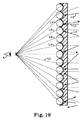
図4は、マイクロレンズシーティングに衝突する発散エネルギーの略図である。各マイクロレンズは、異なる視点から入射エネルギーを「見る」ために、その上に又はその中に画像Iが形成される材料層の部分は、各マイクロレンズによって異なる。したがって、各マイクロレンズに関連した一意的な画像が材料層の中に形成される。 FIG. 4 is a schematic diagram of the diverging energy impinging on the microlens sheeting. Since each microlens “sees” the incident energy from a different viewpoint, the portion of the material layer on which or in which the image I is formed differs from one microlens to another. Thus, a unique image associated with each microlens is formed in the material layer.
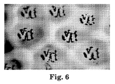
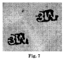
画像化の後、拡大されたオブジェクトのサイズに依存して、オブジェクトの全画像又は部分画像が、各微小球の背後の放射線感応材料の中に存在する。実際のオブジェクトが画像として微小球の背後に再生される程度は、微小球への入射エネルギー密度に依存する。拡大されたオブジェクトの部分は、複数のマイクロレンズの領域から十分遠い場合があるため、それらの微小球への入射エネルギーは、その材料を変性するために必要とされる放射線濃度より低いエネルギー密度を有する。その上、空間的に拡大された画像については、固定されたNAレンズにより画像化されるときには、拡大されたオブジェクトの全部分についてシーティングの全部が入射放射線に暴露されるわけではない。結果として、オブジェクトのそれらの部分は、放射線感応媒体において変性されず、オブジェクトの部分画像のみが微小球の背後に見える。図5は、個々の微小球に隣接した放射線感応層の中に形成されたサンプル画像を描写し、更に、記録された画像は合成画像の完全な複製から部分的な複製までの範囲にわたることを示す、マイクロレンズシーティングの断面の透視図である。図6及び7は、本発明により画像化されたマイクロレンズシーティングの光学顕微鏡写真であり、この中で放射線感応層はアルミニウム層である。その中で見られるように、画像の幾つかは完全であり、及び他のものは部分的である。 After imaging, depending on the size of the magnified object, a full or partial image of the object is present in the radiation sensitive material behind each microsphere. The degree to which an actual object is reproduced as an image behind the microsphere depends on the incident energy density to the microsphere. Because the magnified part of the object may be far enough from the area of multiple microlenses, the energy incident on those microspheres will have an energy density that is lower than the radiation density required to modify the material. Have. Moreover, for a spatially magnified image, not all of the sheeting for all parts of the magnified object is exposed to incident radiation when imaged with a fixed NA lens. As a result, those parts of the object are not denatured in the radiation sensitive medium and only a partial image of the object is visible behind the microsphere. FIG. 5 depicts a sample image formed in a radiation-sensitive layer adjacent to individual microspheres, and further, the recorded image can range from complete to partial reproduction of the composite image. It is a perspective view of the cross section of the microlens sheeting shown. 6 and 7 are optical micrographs of the microlens sheeting imaged according to the present invention, in which the radiation sensitive layer is an aluminum layer. As can be seen, some of the images are complete, and others are partial.
これらの合成画像はまた、実オブジェクトのすべて異なる視点による、部分的及び完全なものの両方の、多くの画像を共に合計した結果として考えられる。多くの一意性の画像が、ミニチュアレンズのアレイを通して形成され、それらのすべてが異なる有利な地点からオブジェクト又は画像を「見ている」。画像の形状と、画像化エネルギー源が受け取られた方向と、に依存して、画像の透視図が、個々のミニチュアレンズの背後に、材料層の中に作成される。しかしながら、レンズが見るすべてのものが放射線感応材料の中に記録されるわけではない。放射線感応材料を変性するために十分なエネルギーを有するレンズによって見られた画像又はオブジェクトの部分のみが記録される。 These composite images can also be considered as a result of summing together many images, both partial and complete, from all different viewpoints of the real object. Many unique images are formed through an array of miniature lenses, all of which “see” the object or image from different advantageous points. Depending on the shape of the image and the direction in which the imaging energy source was received, a perspective view of the image is created in the material layer behind the individual miniature lenses. However, not everything that the lens sees is recorded in the radiation sensitive material. Only the portion of the image or object viewed by a lens with sufficient energy to modify the radiation sensitive material is recorded.
画像化されることになる「オブジェクト」は、「オブジェクト」の輪郭を描くことによるか又はマスクの使用により、強い光源の使用を通して、形成される。このように合成の態様を有するように記録された画像については、オブジェクトからの光は広範囲の角度にわたって放射しなければならない。オブジェクトから放射する光がオブジェクトの単一点から来ているとともに、広範囲の角度にわたって放射しているとき、すべての光線は、オブジェクトについての情報を伝えているが、情報はその単一点のみから伝えられ、光線の角度の視点からである。光線によって伝えられるとき、オブジェクトについての相対的に完全な情報を有するためには、光は、オブジェクトを構成する点の集まりから広範囲の角度にわたって放射しなければならないことを考慮されたい。本発明では、オブジェクトから発する光線の角度の範囲は、オブジェクトとマイクロレンズ材料との間に差し挟まれた光学素子によって制御される。これらの光学素子は、合成画像を生成するために必要な最適な範囲の角度を与えるように選ばれる。光学素子の最良の選択は、それによって錐の頂点がオブジェクトの位置で終了するような光錐を結果として生じる。最適な円錐角は、約40度を超える。 The “object” to be imaged is formed through the use of a strong light source, either by delineating the “object” or by using a mask. For images thus recorded to have a composite aspect, light from the object must radiate over a wide range of angles. When light emanating from an object comes from a single point on the object and emits over a wide range of angles, all rays carry information about the object, but information is only transmitted from that single point. From the viewpoint of the angle of the ray. Consider that light must radiate over a wide range of angles from a collection of points that make up an object, in order to have relatively complete information about the object when conveyed by a ray. In the present invention, the range of angles of light rays emitted from the object is controlled by an optical element sandwiched between the object and the microlens material. These optical elements are chosen to give the optimal range of angles necessary to produce a composite image. The best choice of optical element results in a light cone so that the cone vertex ends at the position of the object. The optimum cone angle is greater than about 40 degrees.
オブジェクトは、ミニチュアレンズにより縮小され、オブジェクトからの光は、ミニチュアレンズの裏側に対するエネルギー感応コーティングに集束する。レンズの裏側の集束スポット又は画像の実際の位置は、オブジェクトから発生する入射光線の方向に依存する。オブジェクト上の点から発する各光錐は、ミニチュアレンズの一部を照らし、十分なエネルギーにより照らされたミニチュアレンズのみが、オブジェクトのその点の永続的画像を記録する。 The object is reduced by the miniature lens and the light from the object is focused on the energy sensitive coating on the back side of the miniature lens. The actual position of the focused spot or image on the back side of the lens depends on the direction of the incident light rays originating from the object. Each light cone emanating from a point on the object illuminates a portion of the miniature lens, and only the miniature lens illuminated by sufficient energy records a permanent image of that point of the object.
幾何学的な光学を使用して、本発明による様々な合成画像の形成を説明する。先に述べたように、以下に記載される画像化プロセスは、限定するわけではないが、本発明の好ましい実施形態である。 The formation of various composite images according to the present invention will be described using geometric optics. As noted above, the imaging process described below is, but is not limited to, a preferred embodiment of the present invention.
A.シーティングの上方に浮動する合成画像の作成
図8を参照すると、入射エネルギー100(この例では、光)が、光源の中のあらゆる不均一性を均質化するために、光ディフューザー101の上に導かれる。広く散乱した光100aは光コリメーター102により捉えられ、視準されて、均一に分配された光100bとして発散レンズ105aの方に向かう。発散レンズから、光線100cがマイクロレンズシーティング106の方に向かって発散する。
A. Creating Composite Image Floating Above Sheeting Referring to FIG. 8, incident energy 100 (in this example, light) is directed onto the
マイクロレンズシーティング106に衝突する光線のエネルギーは、複数のマイクロレンズ111各々により材料層(図解された実施形態では、放射線感応コーティング112)の上に集束される。この集束されたエネルギーは放射線感応コーティング112を変性して画像を提供し、そのサイズ、形状、及び外観は、光線と放射線感応コーティングとの間の相互作用に依存する。
The energy of the light beam impinging on the microlens sheeting 106 is focused onto the material layer (in the illustrated embodiment, the radiation sensitive coating 112) by each of the plurality of
図8に示された配置は、以下に記載されるように、発散光100cがレンズを通って後方に拡大される場合、発散レンズの焦点108aにおいて交差するため、シーティングの上方に浮動するように観測者に見える合成画像を有するシーティングを提供する。別の言い方をすれば、仮定的な「画像光線」が、材料層から微小球の各々を通り、及び発散レンズを通って戻るように追跡される場合、それらは108aで出会うことになり、そこが合成画像の現れるところである。
The arrangement shown in FIG. 8 is such that when the diverging light 100c is magnified backward through the lens, it will float above the sheeting as it intersects at the
B.シーティングの上方に浮動する合成画像の観測
合成画像を有するシーティングは、観測者と同じ側からシーティングに衝突する光(反射光)を使用して、又はシーティングの観測者と反対側からの光(透過光)を使用して、又は両方を使用して見られる場合がある。図9は、反射光の下に見られるとき、観測者の肉眼Aにシーティングの上方に浮動するように見える合成画像の略図である。肉眼は正常視力に矯正されてもよいが、例えば拡大又は特別のビューアーによるなどの別の方法での支援は受けない。画像化されたシーティングが、視準されているか又は散乱している場合がある反射光により照らされているとき、光線は画像化されたシーティングから、光線に突き当てられた材料層によって決定された方式で、反射して戻される。定義により、材料層の中に形成された画像は、材料層の非画像化部分とは異なり、そのため画像は知覚され得る。
B. Observation of a composite image floating above the sheeting Sheeting with a composite image uses light that strikes the sheeting from the same side as the observer (reflected light) or light from the opposite side of the sheeting observer (transmission) Light) or both. FIG. 9 is a schematic illustration of a composite image that appears to float above the sheeting to the viewer's naked eye A when viewed under reflected light. The unaided eye may be corrected to normal vision, but is not otherwise supported, such as by magnification or by a special viewer. When the imaged seating is illuminated by reflected light that may be collimated or scattered, the light ray is determined from the imaged sheeting by the material layer that is abutted against the light ray. In the way, reflected back. By definition, the image formed in the material layer is different from the non-imaged portion of the material layer so that the image can be perceived.
例えば、光L1は、材料層により反射されて観測者の方に戻される場合がある。しかしながら、材料層は、その画像化された部分から光L2を反射して観測者の方に多くを戻さない又は全く戻さない場合がある。したがって、観測者は108aにおいて光線が存在しないことを検出する場合があり、その和が108aにおいてシーティングの上方に浮動するように見える合成画像を作成する。要するに、光は画像化された部分を除くシーティング全体から反射されてもよく、これは相対的に暗い合成画像が108aにおいて見えることを意味する。 For example, the light L1 may be reflected by the material layer and returned to the observer. However, the material layer may reflect the light L2 from its imaged portion and not return much to the viewer or not at all. Thus, the observer may detect the absence of a ray at 108a, creating a composite image that appears to float above the sheeting at 108a. In short, light may be reflected from the entire sheeting except for the imaged portion, which means that a relatively dark composite image is visible at 108a.
合成画像を提供するのに必要とされるコントラスト効果を提供するために、非画像化材料が入射光を吸収又は透過すること、及び画像化された材料が入射光を各々反射する又は部分的に吸収することもまた可能である。そうした状況下での合成画像は、相対的に暗く見えるシーティングの残りの部分と比べて、相対的に明るい合成画像として見える。この合成画像は、焦点108aのところに画像を作成する実際にある光であり、光が存在しないわけではないため、「実像」と呼ばれる場合がある。これらの可能性の様々な組み合わせが所望のように選択できる。
The non-imaging material absorbs or transmits incident light and the imaged material reflects or partially reflects incident light to provide the contrast effect required to provide a composite image It is also possible to absorb. The composite image under such circumstances appears as a relatively bright composite image compared to the rest of the sheeting that appears relatively dark. This composite image is actually light that creates an image at the
特定の画像化されたシーティングはまた、図10に示されたように、透過光により見ることもできる。例えば、材料層の画像化された部分が半透明であり、及び画像化されていない部分が半透明でないとき、大部分の光L3は材料層により吸収されるか又は反射されるが、透過光L4は、材料層の画像化された部分を通過して複数のマイクロレンズにより焦点108aの方に導かれる。合成画像は、焦点においてはっきりと見えるようになり、そこでは、この実施例ではそれがシーティングの残りの部分より明るく見えるようになる。この合成画像は、焦点108aのところに画像を作成する実際にある光であり、光が存在しないわけではないため、「実像」と呼ばれる場合がある。
Certain imaged sheeting can also be viewed by transmitted light, as shown in FIG. For example, when the imaged portion of the material layer is translucent and the non-imaged portion is not translucent, most of the light L3 is absorbed or reflected by the material layer, but transmitted light L4 passes through the imaged portion of the material layer and is directed toward the
あるいは、材料層の画像化された部分が半透明ではないが、材料層の残りの部分が半透明である場合、画像の区域に透過光が存在しないことは、シーティングの残りの部分より暗く見える合成画像を提供する。 Alternatively, if the imaged portion of the material layer is not translucent but the rest of the material layer is translucent, the absence of transmitted light in the area of the image will appear darker than the rest of the sheeting Provide a composite image.
C.シーティングの下方に浮動する合成画像の作成
観測者からシーティングの反対側に浮遊しているように見える合成画像がまた提供されてもよい。シーティングの下方に浮動するこの浮動画像は、図8に示された発散レンズ105の代わりに収束レンズを使用することにより作成できる。図11を参照すると、入射エネルギー100(この例では、光)が、光源の中のあらゆる不均一性を均質化するために、ディフューザー101の上に導かれる。散乱光100aは次にコリメーター102により収集され、視準されて、光100bとして収束レンズ105bの方に向かう。収束レンズから光線100dが、収束レンズと収束レンズの焦点108bとの間に設置されたマイクロレンズシーティング106に入射する。
C. Creating a Composite Image that Floats Below the Seating A composite image that appears to be floating on the opposite side of the sheeting from the observer may also be provided. This floating image floating below the sheeting can be created by using a converging lens instead of the diverging lens 105 shown in FIG. Referring to FIG. 11, incident energy 100 (in this example, light) is directed onto the
マイクロレンズシーティング106に衝突する光線のエネルギーは、複数のマイクロレンズ111各々により材料層(図解された実施形態では、放射線感応コーティング112)の上に集束される。この集束されたエネルギーは放射線感応コーティング112を変性して画像を提供し、そのサイズ、形状、及び外観は、光線と放射線感応コーティングとの間の相互作用に依存する。図11に示された配置は、以下に記載されるように、収束光100dがシーティングを通って伸びる場合、発散レンズ(diverging lens)の焦点108bにおいて交差するため、シーティングの下方に浮動するように観測者に見える合成画像を有するシーティングを提供する。別の言い方をすれば、仮定的な「画像光線」が、収束レンズ105bから微小球の各々を通り、各マイクロレンズに関連した材料層の中の画像を通って追跡される場合、それらは108bで出会うことになり、そこが合成画像の現れるところである。
The energy of the light beam impinging on the microlens sheeting 106 is focused onto the material layer (in the illustrated embodiment, the radiation sensitive coating 112) by each of the plurality of
D.シーティングの下方に浮動する合成画像の観測
シーティングの下方に浮動するように見える合成画像を有するシーティングもまた、反射光、透過光、又は両方の中で見ることができる。図12は、反射光の下で見られるとき、シーティングの下方に浮動するように見える合成画像の略図である。例えば、光L5は、材料層により反射されて観測者の方に戻る場合がある。しかしながら、材料層は、その画像化された部分から光L6を反射して、観測者の方に多くを戻さない又は全く戻さない場合がある。したがって、観測者は108bにおいて光線が存在しないことを検出する場合があり、その和は108bにおいてシーティングの下方に浮動するように見える合成画像を作成する。要するに、光は画像化された部分を除くシーティング全体から反射されてもよく、これは相対的に暗い合成画像が108bにおいてはっきりと見えることを意味する。
D. Observation of Composite Image Floating Below Sheeting Sheeting with a composite image that appears to float below the sheeting can also be seen in reflected light, transmitted light, or both. FIG. 12 is a schematic illustration of a composite image that appears to float below the sheeting when viewed under reflected light. For example, the light L5 may be reflected by the material layer and return to the observer. However, the material layer may reflect the light L6 from its imaged portion and not return much to the observer or not at all. Thus, the observer may detect the absence of a ray at 108b, and the sum creates a composite image that appears to float below the sheeting at 108b. In short, the light may be reflected from the entire sheeting except the imaged portion, which means that a relatively dark composite image is clearly visible at 108b.
合成画像を提供するのに必要とされるコントラスト効果を提供するために、非画像化材料が入射光を吸収又は透過すること、及び画像化された材料が入射光を各々反射する又は部分的に吸収することもまた可能である。そうした状況下での合成画像は、相対的に暗く見えるシーティングの残りの部分と比べて、相対的に明るい合成画像として見える。これらの可能性の様々な組み合わせが所望のように選択できる。 The non-imaging material absorbs or transmits incident light and the imaged material reflects or partially reflects incident light to provide the contrast effect required to provide a composite image It is also possible to absorb. The composite image under such circumstances appears as a relatively bright composite image compared to the rest of the sheeting that appears relatively dark. Various combinations of these possibilities can be selected as desired.
特定の画像化されたシーティングはまた、図13に示されたように、透過光により見ることもできる。例えば、材料層の画像化された部分が半透明であり、及び画像化されていない部分が半透明でないとき、大部分の光L7は材料層により吸収されるか又は反射されるが、透過光L8は、材料層の画像化された部分を通過する。それらの光線の延長線は、本明細書では「画像光線」と呼ばれ、入射光の方向に戻り、108bのところに合成画像の形成を結果として生じる。合成画像は、焦点においてはっきりと見えるようになり、そこでは、この実施例ではそれがシーティングの残りの部分より明るく見えるようになる。 Certain imaged sheeting can also be viewed by transmitted light, as shown in FIG. For example, when the imaged portion of the material layer is translucent and the non-imaged portion is not translucent, most of the light L7 is absorbed or reflected by the material layer, but transmitted light L8 passes through the imaged portion of the material layer. These ray extensions, referred to herein as “image rays”, return to the direction of the incident light, resulting in the formation of a composite image at 108b. The composite image becomes clearly visible at the focus, where in this example it appears brighter than the rest of the sheeting.
あるいは、材料層の画像化された部分が半透明ではないが、材料層の残りの部分が半透明である場合、画像の区域に透過光が存在しないことは、シーティングの残りの部分より暗く見える合成画像を提供する。 Alternatively, if the imaged portion of the material layer is not translucent but the rest of the material layer is translucent, the absence of transmitted light in the area of the image will appear darker than the rest of the sheeting Provide a composite image.
E.複合画像
本発明の原理により作製された合成画像は、それらが長さと幅を有することと、シーティングの下方、若しくはシーティングの面内、若しくはシーティングの上方に見えることと、を意味する二次元、又はそれらが、長さ、幅、及び高さを有することを意味する三次元のいずれかであるように見える場合がある。三次元の合成画像は、シーティングの下方若しくは上方にのみ見える場合もあるし、又は所望のように、シーティングの下方、シーティングの面内、及びシーティングの上方のいずれかの組み合わせにおいて見える場合もある。「シーティングの面内に」という用語は、シーティングが平らに置かれているとき、シーティングの面をただ一般に指す。即ち、平らでないシーティングもまた、本明細書でその語句が使用されるように、少なくとも部分的に「シーティングの面内に」あるように見える合成画像を有することができる。
E. Composite images Composite images made in accordance with the principles of the present invention are two-dimensional, meaning that they have length and width and appear below the sheeting, or in the plane of the sheeting, or above the sheeting, or They may appear to be any of the three dimensions meaning that they have a length, width, and height. The three-dimensional composite image may be visible only below or above the sheeting, or may be visible at any combination below the sheeting, in the plane of the sheeting, and above the sheeting, as desired. The term “in the plane of the sheeting” generally refers only to the surface of the sheeting when the sheeting is laid flat. That is, a non-planar sheeting can also have a composite image that appears to be at least partially “in the plane of the sheeting”, as that term is used herein.
三次元の合成画像は、単一の焦点において見えるのではなく、むしろシーティングの一方の側から又はシーティングを通って、もう一方の側上の点までの範囲の焦点を有する焦点の連続体を有する複数の画像の合成物として見える。これは、複数の焦点において材料層を画像化するように、シーティング又はエネルギー源のいずれかをもう一方に対し順次移動させることにより(複数の異なるレンズを提供することによるのではなく)好ましくは実現される。結果として生じる空間的に複合した画像は、多くの個々のドットから本質的になる。この画像は、シーティングの平面に対する3つのデカルト座標のいずれにおいても空間的範囲を有することができる。 The three-dimensional composite image is not visible at a single focal point, but rather has a continuum of focal points with a range of focal points from one side of the sheeting or through the sheeting to a point on the other side Looks like a composite of multiple images. This is preferably achieved by moving either the sheeting or energy source sequentially relative to the other (rather than providing multiple different lenses) to image the material layer at multiple focal points. Is done. The resulting spatially complex image consists essentially of many individual dots. This image can have a spatial extent in any of the three Cartesian coordinates relative to the plane of the sheeting.
別の種類の効果では、合成画像は、マイクロレンズを備えたシーティングの領域中に移動するように作製されることができ、そこでそれは消失する。この種類の画像は、不透明のマスクをマイクロレンズを備えた材料に接触して設置し、マイクロレンズを備えた材料の一部への画像化光を部分的に遮蔽することを追加した、浮揚の例に類似したやり方により組み立てられる。こうした画像を見るとき、画像は、画像化光が接触マスクにより低減されるか又は排除された領域の中に移動するように作製され得る。画像は、その領域において「消失するように」見える。 In another type of effect, the composite image can be made to move into the area of the sheeting with microlenses, where it disappears. This type of image is a levitation mask, with the addition of an opaque mask in contact with the material with the microlens and the partial shielding of the imaging light onto the part of the material with the microlens. It is assembled in a manner similar to the example. When viewing such an image, the image can be made to move into areas where imaging light is reduced or eliminated by the contact mask. The image appears “disappearing” in that area.
本発明により形成された合成画像は、非常に広い視角を有することができ、これは観測者がシーティングの平面と見る軸との間の広範囲の角度にわたって合成画像を見ることができることを意味する。およそ70〜80マイクロメートルの平均直径を有するガラス微小球の単層からなるマイクロレンズシーティングの中に形成された合成画像は、0.64の開口数を有する非球面レンズを使用するとき、その中心軸が入射エネルギーの光軸により決定される円錘形の視野内で目に見える。環境光の下で、そのように形成された合成画像は、約80〜90度の全角の円錐にわたって見える。より小さな発散又はより低いNAを有する画像化レンズを利用することにより、より小さな半角の円錐を形成することができる。 The composite image formed according to the present invention can have a very wide viewing angle, meaning that the observer can see the composite image over a wide range of angles between the plane of the sheeting and the viewing axis. The composite image formed in a microlens sheeting consisting of a single layer of glass microspheres having an average diameter of approximately 70-80 micrometers is centered when using an aspheric lens with a numerical aperture of 0.64 Visible in a frustum-shaped field whose axis is determined by the optical axis of the incident energy. Under ambient light, the composite image so formed is visible over a full-angle cone of about 80-90 degrees. By utilizing imaging lenses with smaller divergence or lower NA, smaller half-angle cones can be formed.
本発明のプロセスにより形成された複数の画像はまた、限定された視角を有するように構築されることもできる。換言すれば、画像は、特別の方向から、又はその方向の微かな角度の変異により見られた場合にのみ見られる。こうした複数の画像は、最後の非球面レンズへの入射光が、レンズの一部分のみがレーザー放射により照らされるように調整されることを除いて、以下の実施例1に記載された方法と同様に形成される。レンズに入射エネルギーを部分的に充填することは、マイクロレンズを備えたシーティングへ入射した発散光の限定された錐を結果として生じる。アルミニウムがコーティングされたマイクロレンズシーティングについては、合成画像は、限定された視野の円錐内でのみ、ダークグレーの画像としてライトグレーの背景上に見える。画像は、マイクロレンズシーティングに対して浮動しているように見える。 Multiple images formed by the process of the present invention can also be constructed to have a limited viewing angle. In other words, an image is only seen when viewed from a particular direction or by a slight angle variation in that direction. These multiple images are similar to the method described in Example 1 below, except that the light incident on the last aspheric lens is adjusted so that only a portion of the lens is illuminated by the laser radiation. It is formed. Partially filling the lens with incident energy results in a limited cone of diverging light incident on the sheeting with the microlens. For an aluminum coated microlens sheeting, the composite image appears as a dark gray image on a light gray background only within a limited field of view cone. The image appears to float relative to the microlens sheeting.
本発明は次の実施例により更に説明されるが、これは便宜のため、特定の図を参照する場合がある。 The invention is further illustrated by the following examples, which may, for convenience, refer to specific figures.
(実施例1)
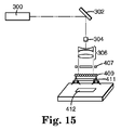
本実施例は、アルミニウム材料層を有する埋め込みレンズシーティング、及びシーティングの上方に浮動するように見える合成画像を記載する。図14に描写された種類の光学ユニットが使用されて浮動画像を形成した。光学ユニットは、Qスイッチモードで、1.06マイクロメートルのその基本波長において動作する「スペクトラ・フィジックス・クォンタ−レイ(Spectra Physics Quanta-Ray)(商標)DCR−2(10)」Nd:YAGレーザー300からなった。このレーザーのパルス幅は、典型的には10〜30nsである。レーザーに続いて、エネルギーが、99%反射鏡302、摺りガラスディフューザー304、5Xビーム拡大テレスコープ306、並びに0.64の開口数及び39.0mmの焦点距離を有する非球面レンズ308により方向を変えられた。非球面レンズ308からの光は、XYZステージ310の方に導かれた。ステージは、3つの直線ステージから構成されており、及びエアロテク社(Aerotech Inc.)(ペンシルベニア州ピッツバーグ(Pittsburgh))から表記「ATS50060」のもとに入手可能である。1つの直線ステージが使用されて、非球面レンズを、非球面の焦点とマイクロレンズシーティングの間の軸(z軸)に沿って移動させ、及び他の2つのステージは、シーティングが、光軸に対して2つの相互に直交する水平軸の中で移動できるようにした。
(Example 1)
This example describes an embedded lens sheeting with an aluminum material layer and a composite image that appears to float above the sheeting. An optical unit of the type depicted in FIG. 14 was used to form a floating image. The optical unit is a “Spectra Physics Quanta-Ray ™ DCR-2 (10)” Nd: YAG laser operating at its fundamental wavelength of 1.06 micrometers in Q-switch mode. It consisted of 300. The pulse width of this laser is typically 10-30 ns. Following the laser, the energy is redirected by a 99
レーザー光は、摺りガラスディフューザー304の方に導かれて、熱のレンズ効果により生じたあらゆるビームの不均質性を排除した。ディフューザーに直ぐ隣接した5Xビーム拡大テレスコープ306は、ディフューザーからの発散光を視準し、光線を拡大して非球面レンズ308を満たした。
The laser light was directed towards the
この実施例では、非球面レンズは、レンズの焦点がマイクロレンズシーティング312の1cm上方であるように、XYZステージのXY平面の上方に配置された。ジェンテック社(Gentec, Inc.)(カナダ、ケベック州、セイント・フェイ(Saint-Fey))から機械的マスク付きの表記「ED500」のもとに入手可能である開口部を備えたエネルギーメーターを使用してシーティング平面におけるエネルギー密度を制御した。レーザー出力は、非球面レンズの焦点から1cmのエネルギーメーターの照らされた区域にわたって、1平方センチメートル当たりおよそ8ミリジュール(8mJ/cm2)を得るように調整された。80nmの厚さのアルミニウム放射線感応層を有する埋め込みレンズシーティング312のサンプルが、アルミニウムコーティングされた面が非球面レンズ308から離れて向くように、XYZステージ310に取り付けられた。
In this example, the aspherical lens was placed above the XY plane of the XYZ stage so that the focal point of the lens was 1 cm above the
エアロテク社(Aerotech Inc.)(ペンシルベニア州ピッツバーグ(Pittsburgh))から表記「U21」のもとに入手可能であるコントローラーが、XYZステージ312(the XYZ stage 312)の移動のために必要な制御信号、及びレーザー300のパルス発生のための制御電圧を提供した。ステージは、CADファイルをコントローラーの中に、x−y−z座標情報と、移動コマンドと、画像を生成するために必要なレーザー発射コマンドと共に取り込むことにより移動された。マイクロレンズを備えた材料の上方に間隙を介して画像を描くために、X、Y、及びZステージの移動をレーザーのパルス発生に合わせることにより、不定の複合合成画像が形成された。ステージ速度は、10Hzのレーザーパルス速度について50.8センチメートル/分に調整された。これは、複数のマイクロレンズに隣接したアルミニウム層の中に連続した合成線を形成した。
A controller available under the designation “U21” from Aerotech Inc. (Pittsburgh, Pa.) Is a control signal required for movement of the XYZ stage 312 (the XYZ stage 312), And a control voltage for
マイクロレンズを備えたシーティングが環境光の中で見られるとき、複数の画像はライトグレーの背景に対してダークグレーであった。焦点とビーズ付きシーティングの表面との間の固定した1cmの間隔について、結果として生じる画像は、シーティングのおよそ1cm上方に浮動するように見える平面的な合成画像であった。その上、合成画像は、観測者の視点との関連において、かなり大きい移動を示し、そのため観測者は、視角に依存して合成画像の異なる態様を容易に見ることができた。 When the sheeting with microlenses was seen in ambient light, the images were dark gray against a light gray background. For a fixed 1 cm spacing between the focal point and the surface of the beaded sheeting, the resulting image was a planar composite image that appeared to float approximately 1 cm above the sheeting. In addition, the composite image showed quite a large movement in relation to the observer's viewpoint, so that the observer could easily see different aspects of the composite image depending on the viewing angle.
(実施例2)
本実施例では、透明なミラー放射線感応層を有する露出レンズシーティング構造物が使用されて、マイクロレンズシーティングの下方に浮動するように見える合成画像を形成した。実施例1に使用された光学ユニットもまた本実施例で使用された。マイクロレンズを備えたシーティングは、レンズがマイクロレンズシーティングにほとんど接触するように、非球面レンズ308に対して配置された。レーザー出力は、非球面レンズの直下でおよそ14mJ/cm2を実現するように調整された。露出レンズシーティングは、米国特許第3,801,183号に記載されるように、部分的に埋め込まれた微小球から構成され、硫化亜鉛(ZnS)誘電体ミラーの蒸気が、微小球の片側上に付着した。ZnS層の厚さは、公称60nmであった。実施例1のように、レーザーは、シーティングが50.8cm/分で移動される間に10Hzで動作し、マイクロレンズを備えたシーティングの中に連続した合成線の形成を結果として生じた。「球」パターン(4つの内接する弧を有する円)が、ステージングシステムにより描かれた。
(Example 2)
In this example, an exposed lens sheeting structure with a transparent mirror radiation sensitive layer was used to form a composite image that appeared to float below the microlens sheeting. The optical unit used in Example 1 was also used in this example. The sheeting with the microlens was placed against the
環境光の下で、球はホワイト/イエローの背景に対して暗い画像として見えた。暗い合成画像は、シーティングのおよそ39mm下方に浮動するように見えた。合成画像の場所は、非球面レンズの焦点の場所に対応し、これは本実施例については、レンズのおよそ39mm後ろと関連付けられた。 Under ambient light, the sphere appeared as a dark image against a white / yellow background. The dark composite image appeared to float approximately 39 mm below the sheeting. The location of the composite image corresponds to the location of the focal point of the aspheric lens, which for this example was associated with approximately 39 mm behind the lens.
(実施例3)
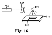
本実施例は、アルミニウム放射線感応層を有する露出レンズシーティングの中に、単一の非球面レンズの代わりにレンズアレイを使用して、合成画像を形成することを記載する。図15に描写された種類の光学ユニットが使用されて、浮動する合成画像を形成した。光学ユニットは、Qスイッチレーザー300、99%反射鏡302、光学ディフューザー304、及びビーム拡大テレスコープ306からなった。本実施例に使用された光学ユニットのこれらの構成要素は、実施例1に記載されたものと同一である。本実施例の光学ユニットにまた包含されたのは、二次元のレンズアレイ407、反射マスク409、及び負の両凹レンズ411であった。レーザー放射線に暴露されることになるマイクロレンズを備えた材料412の区域と一致する反射マスク409の区域は透明であったが、マスクの残りの表面は不透明であるか又は反射性であった。
(Example 3)
This example describes the use of a lens array instead of a single aspheric lens in an exposed lens sheet with an aluminum radiation sensitive layer to form a composite image. An optical unit of the type depicted in FIG. 15 was used to form a floating composite image. The optical unit consisted of a Q-switched
レンズアレイ407は、MEMSオプティカル社(MEMS Optical, LLC)(アラバマ州ハンツビル(Huntsville))から表記「3038」のもとに入手可能である溶融シリカ屈折マイクロレンズアレイからなった。この稠密充填球面レンズアレイは、75mmの直径及び150mmの負の焦点距離を有する負の両凸レンズ411とほとんど接触して設置された。80nm厚のアルミニウム放射線感応層を有する、露出レンズシーティング412が、負の両凸レンズ411の25mm以内に設置された。マイクロレンズを備えた材料が、マイクロレンズアレイと負の両凸レンズとの組み合わされた光学経路の焦点距離からおよそ1cmに設置された。レーザーからの出力が、マイクロレンズを備えたシーティングの露出レンズ面の表面において、およそ4mJ/cm2を生成するように調整された。単一のレーザーパルスが、画像全体を暴露させるために活性化された。
The
環境光の中で見られるとき、結果として生じる画像化されたマイクロレンズを備えたシーティングは、シーティングのおよそ1cm上方に浮動するように見える複数の画像を明らかにした。画像は、ライトグレーの背景に対してダークグレーに見えた。 When viewed in ambient light, the sheeting with the resulting imaged microlens revealed multiple images that appeared to float approximately 1 cm above the sheeting. The image appeared dark gray against a light gray background.
(実施例4)
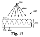
本実施例では、発散光源が、散乱源からの反射により得られた。散乱レフレクターは、直径およそ5mmのセラミックビーズからなった。図16で描写された種類の光学ユニットが本実施例の中で使用された。それは、実施例1に記載されたものに類似したQスイッチNd:YAGレーザー500、続いて入射レーザービームのサイズをおよそ1mmの直径に低減させたテレスコープ502からなった。光は次に、マイクロレンズシーティング512に面するセラミックビーズ504の半球のおよそ4分の1が照らされるように、垂直から十分に逸れた角度でセラミックビーズ504に衝突した。これは、赤外線カメラを通して散乱した放射線を見ることにより確認された。
(Example 4)
In this example, a divergent light source was obtained by reflection from a scattering source. The scattering reflector consisted of ceramic beads with a diameter of approximately 5 mm. An optical unit of the type depicted in FIG. 16 was used in this example. It consisted of a Q-switched Nd:
セラミックビーズ504は、およそ25mmの距離で、XYステージ510の上方に位置付けられた。レーザーからの入射光は、サンプルステージに平行であるように調整された。80nmのアルミニウム放射線感応層を有する埋め込みレンズシーティング512が、XYステージ510に取り付けられ、コントローラーがステージ及びレーザーへの制御信号を提供した。レーザー出力は、マイクロレンズシーティングの表面でおよそ8mJ/cm2を得るように調整された。セラミックビーズ504を照らすことは、最も均一の露光をマイクロレンズを備えたシーティング512の表面に得るように調整された。XYステージ510は、レーザーが10Hzでパルスを発生するのとともに、50.8cm/分で移動された。マイクロレンズを備えたシーティングがセラミックレフレクターからの散乱された放射線に暴露される間に、複合画像がステージにより描かれた。
The
環境光の中で、合成画像はシーティングのおよそ25mm上方に浮動し、及びライトグレーの背景に対してダークグレーに見えた。画像は、観測者の見る位置に対して大きく移動した。透過光の下で、明るい合成画像が、シーティングのおよそ25mm上方に浮動した。 In ambient light, the composite image floated approximately 25 mm above the sheeting and appeared dark gray against a light gray background. The image moved greatly relative to the position seen by the observer. Under transmitted light, a bright composite image floated approximately 25 mm above the sheeting.
(実施例5)
本実施例では、埋め込みレンズシーティングの材料層は、可視スペクトル中の特定の色に同調した多層の光学スタックからなった。マイクロレンズを備えたベースシートの片面上に、薄いフィルム層が真空蒸着及びプラズマ重合により付着されて、クロム層が埋め込みレンズに隣接している、クロム/プラズマ重合ブタジエン/二酸化ケイ素/アルミニウムからなる層順序を得た。個々の材料の厚さは、可視スペクトルのレッド、グリーン、及びブルーの部分の色を得るように調整された。表1は、調製された個々の材料の具体的な厚さを提供する。
(Example 5)
In this example, the material layer of the embedded lens sheeting consisted of a multilayer optical stack tuned to a specific color in the visible spectrum. A layer of chromium / plasma-polymerized butadiene / silicon dioxide / aluminum, with a thin film layer deposited by vacuum deposition and plasma polymerization on one side of a base sheet with microlenses and a chromium layer adjacent to the embedded lens Got the order. The thickness of each material was adjusted to obtain the red, green, and blue portions of the visible spectrum. Table 1 provides specific thicknesses of the individual materials prepared.

コーティングされたマイクロレンズベースシートは次に、多層がラミネート材料に接触して、裏材に積層された。マイクロレンズシーティングのライナーが次に取り除かれ、上記の表により与えられた色を有する埋め込みレンズの正面を暴露した。 The coated microlens base sheet was then laminated to the backing, with the multilayer contacting the laminate material. The microlens sheeting liner was then removed to expose the front of the embedded lens having the color given by the table above.
実施例1に記載されたような光学ユニットを使用して本実施例のサンプルを画像化した。本実施例では、非球面の焦点は、マイクロレンズシーティングの1cm上方に配置された。レーザー出力は、マイクロレンズシーティングの表面のところで、5mJ/cm2のエネルギー密度を得るように調整された。多層スタックの光学的性質は、照射された領域において変性された。実施例1に記載されたものに類似した方式で、球パターンが描かれて、多層スタックの中に複数の画像を提供した。 An optical unit as described in Example 1 was used to image the sample of this example. In this example, the aspheric focal point was placed 1 cm above the microlens sheeting. The laser power was adjusted to obtain an energy density of 5 mJ / cm 2 at the surface of the microlens sheeting. The optical properties of the multilayer stack were modified in the irradiated area. A sphere pattern was drawn in a manner similar to that described in Example 1 to provide multiple images in a multilayer stack.
環境光の中で、照射された領域は、マイクロレンズを備えたシーティングの背景の色に対してライトイエローからオレンジの色に見えた。すべての合成画像は、シーティングの上方に浮動するように見え、観測者に対して移動しているように見えた。 In ambient light, the illuminated area appeared light yellow to orange relative to the background color of the seating with microlenses. All composite images appeared to float above the sheeting and appeared to move with respect to the observer.
(実施例6)
本実施例は、色の付いた合成画像を生成するために放射線感応層としての多層同調スタック(tuned stack)の第2の種類を記載する。光学スタックは、埋め込みレンズシーティングからなるマイクロレンズを備えたベースシートの上に調製された。マイクロレンズを備えたベースシートの片面の上には、薄いフィルム層が真空蒸着により付着されて、以下の表2に示されるように、クロム/クライオライト/アルミニウム(Cr/Na3AlF6/Al)、クロム/二酸化ケイ素/アルミニウム(Cr/SiO2/Al)、又はクロム/フッ化マグネシウム/アルミニウム(Cr/MgF2/Al)からなる層順序を得た。誘電体材料、SiO2、Na3AlF6、及びMgF2の厚さは、可視スペクトルにおいて多様な色を得るように調整された。表2は、様々なサンプルにおいて調製された個々の材料の具体的な厚さを提供する。
(Example 6)
This example describes a second type of multilayer tuned stack as a radiation sensitive layer to produce a colored composite image. The optical stack was prepared on a base sheet with microlenses consisting of embedded lens sheeting. On one side of the base sheet with microlenses, a thin film layer is deposited by vacuum deposition, and as shown in Table 2 below, chromium / cryolite / aluminum (Cr / Na 3 AlF 6 / Al ), Chromium / silicon dioxide / aluminum (Cr / SiO 2 / Al) or chromium / magnesium fluoride / aluminum (Cr / MgF 2 / Al). Dielectric materials, SiO 2, Na 3 AlF 6 , and the thickness of the MgF 2 was adjusted to obtain a variety of colors in the visible spectrum. Table 2 provides specific thicknesses of individual materials prepared in various samples.
コーティングされたマイクロレンズベースシートは次に、多層がラミネート材料に接触するように、裏材に積層された。マイクロレンズシーティングのライナーが次に取り除かれ、上記の表により与えられた色を有する埋め込みレンズの正面を暴露した。 The coated microlens base sheet was then laminated to the backing so that the multilayer was in contact with the laminate material. The microlens sheeting liner was then removed to expose the front of the embedded lens having the color given by the table above.
実施例1に記載された光学ユニットを使用してこれらのサンプルを画像化した。本実施例では、最後の非球面レンズの位置が、サンプルにほとんど接触して配置されて、シーティングの下方に浮動するように見える合成画像を提供した。表2に示されたように、レーザーエネルギーは、各々の多層スタックの光学的性質を永久に変えるエネルギー密度を得るように調整された。英数字「SAMPLE」が、実施例1に記載されたものと類似した方式で、この材料中に画像として描かれた。環境光の中で、合成画像は、マイクロレンズを備えたシーティングの背景の色に対してホワイト/イエローの輪郭を有して暗く見えた。すべての合成画像は、シーティングのおよそ39mm下方に浮動するように見え、シーティングを見る観測者に関して移動するように見えた。 These samples were imaged using the optical unit described in Example 1. In this example, the final aspheric lens position was placed in close contact with the sample to provide a composite image that appeared to float below the sheeting. As shown in Table 2, the laser energy was adjusted to obtain an energy density that permanently changed the optical properties of each multilayer stack. The alphanumeric character “SAMPLE” was drawn as an image in this material in a manner similar to that described in Example 1. In ambient light, the composite image appeared dark with a white / yellow outline against the background color of the sheeting with microlenses. All composite images appeared to float approximately 39 mm below the sheeting and appeared to move with respect to the observer viewing the sheeting.
(実施例7)
本実施例では、色の合成画像が、放射線感応層として、50原子百分率の銀及び50原子百分率の亜鉛(Ag50Zn50)の相変化合金、並びにクロム及び二酸化ケイ素からなる同調二層スタック(tuned bilayer stack)を使用して、埋め込みレンズシーティングの中に形成された。同調二層(tuned bilayer)は、可視電磁スペクトルのブルーの部分におけるスペクトル反射率を強化するが、相変化合金は、適用された放射線によってアブレーションされなかった。放射線感応層は、実施例5の多層スタックの薄いフィルム層をマイクロレンズを備えたベースシートの方に付着するために使用された手順に類似した方式で、封入レンズシーティングのスペーサー層の上に付着された。第1に、クロム及び二酸化ケイ素の層が、40nm及び260nmの厚さの高分子スペーサー層の上に各々付着された。次に、Ag50Zn50合金の80nmの厚さの層が、二酸化ケイ素層の上にスパッタ付着された。サンプルは次に積層され、及びマイクロレンズシーティングの透明な部分を暴露するために剥離された。
(Example 7)
In this example, the color composite image is a tuned bilayer stack consisting of a phase change alloy of 50 atomic percent silver and 50 atomic percent zinc (Ag 50 Zn 50 ) and chromium and silicon dioxide as a radiation sensitive layer. tuned bilayer stack) was formed in the embedded lens sheeting. The tuned bilayer enhances the spectral reflectance in the blue part of the visible electromagnetic spectrum, but the phase change alloy was not ablated by the applied radiation. The radiation sensitive layer is deposited on the encapsulating lens sheeting spacer layer in a manner similar to the procedure used to deposit the thin film layer of the multilayer stack of Example 5 towards the base sheet with the microlenses. It was done. First, chromium and silicon dioxide layers were deposited on 40 nm and 260 nm thick polymer spacer layers, respectively. Next, an 80 nm thick layer of Ag 50 Zn 50 alloy was sputter deposited onto the silicon dioxide layer. The sample was then laminated and peeled away to expose the transparent part of the microlens sheeting.
環境(反射された)光の下で見られるとき、シーティングは、バイオレット−ブルーであるように見えた。実施例1に類似した光学ユニットを使用して、Ag50Zn50放射線感応層を画像化した。Qスイッチレーザーの代わりに、1.06um(um)の波長で動作する連続波Nd:YAGレーザーが、エネルギー源として使用された。パルス幅は、光学ユニット中の音響光学モジュレータの使用により制御された。1次回折ビームが、図14に描写された種類の光学ユニットを通して送られた。封入レンズシーティングのサンプルが、XYZステージに取り付けられた。音響光学モジュレータ中へのレーザー出力が、マイクロレンズを備えた材料において810mWの出力を与えるように調整された。音響光学モジュレータが、100マイクロ秒のパルス幅で、20Hzのパルス発生を実現するように設定された。正の非球面レンズは、実施例1に記載されたように、マイクロレンズを備えた材料の表面の12mm上方に設置された。画像は、レーザー放射線が放射線感応層を暴露する間に、XYZステージにより描かれた。 The sheeting appeared to be violet-blue when viewed under ambient (reflected) light. An optical unit similar to Example 1 was used to image the Ag 50 Zn 50 radiation sensitive layer. Instead of a Q-switched laser, a continuous wave Nd: YAG laser operating at a wavelength of 1.06 um (um) was used as the energy source. The pulse width was controlled by the use of an acousto-optic modulator in the optical unit. A first order diffracted beam was sent through an optical unit of the type depicted in FIG. A sample of encapsulated lens sheeting was attached to the XYZ stage. The laser power into the acousto-optic modulator was adjusted to give 810 mW power in the material with the microlens. The acousto-optic modulator was set to achieve 20 Hz pulse generation with a pulse width of 100 microseconds. The positive aspheric lens was placed 12 mm above the surface of the material with the microlens as described in Example 1. The image was drawn by an XYZ stage while laser radiation exposed the radiation sensitive layer.
シーティングが環境光の中で見られるとき、画像化された領域は、ライトブルーの色に見え、及びマイクロレンズシーティングの約12mm上方に浮動した。 When the sheeting was seen in ambient light, the imaged area appeared a light blue color and floated approximately 12 mm above the microlens sheeting.
(実施例8)
本実施例では、銅の放射線感応層を有する、複製されたレンズ構造が、マイクロレンズシーティングとして使用された。米国特許第5,254,390号に記載された種類の複製されたシーティングが、マイクロレンズシーティングとして使用された。銅の放射線感応層が、シーティングの平らな表面上に、80nmの厚さまで、真空蒸着された。微小複製されたマイクロレンズを備えた材料が、実施例1に記載されたような光学ユニットからレーザー放射線に暴露された。最後の非球面レンズが、マイクロレンズを備えた材料の表面から6.5mm離れた焦点を有して配置された。レーザー出力は、シーティングの表面でおよそ7mJ/cm2を与えるように調整された。レーザーは、XYZステージングが50.8cm/分の速度で移動される間に、10Hzでパルスを発生するように設定された。「球」パターン(4つの内接する弧を有する円)が、サンプルの上方に描かれた。
(Example 8)
In this example, a replicated lens structure with a copper radiation sensitive layer was used as a microlens sheeting. A replicated sheet of the type described in US Pat. No. 5,254,390 was used as the microlens sheeting. A copper radiation sensitive layer was vacuum deposited on the flat surface of the sheeting to a thickness of 80 nm. A material with microreplicated microlenses was exposed to laser radiation from an optical unit as described in Example 1. The last aspheric lens was placed with a focal point 6.5 mm away from the surface of the material with the microlenses. The laser power was adjusted to give approximately 7 mJ / cm 2 at the surface of the sheeting. The laser was set to generate a pulse at 10 Hz while the XYZ staging was moved at a speed of 50.8 cm / min. A “sphere” pattern (circle with four inscribed arcs) was drawn above the sample.
シーティングが環境光中で見られたとき、浮動する球の白っぽい画像が、放射線感応層の銅のような色に対して見ることができた。この合成画像は、シーティングの約6mm上方に浮動するように見えた。 When the sheeting was viewed in ambient light, a whitish image of the floating sphere could be seen against the copper-like color of the radiation sensitive layer. This composite image appeared to float approximately 6 mm above the sheeting.
(実施例9)
本実施例は、平面的な合成画像とシーティングの下方に浮動するように見える合成画像の組み合わせを記載する。80nm厚のアルミニウム放射線感応層を有する露出レンズのマイクロレンズシーティングが、実施例1に記載された光学構成を使用して画像化された。非球面レンズはマイクロレンズシーティングとほとんど接触して配置され、レーザー出力は、サンプル表面において4mJ/cm2を生成するように調整された。コントローラーは、英数字「SAMPLE」を描くようにプログラムされた。吸収マスクが、むき出しのシーティングの上に設置された。このマスクは、従来のコピー機を手段として、英数字の列「3M」を透明シートの上に印刷することにより製造された。周囲の区域がレーザー放射線を透過する一方で、英数字は放射線を吸収した。この吸収マスクを有する露出レンズシーティングは、「SAMPLE」の文字がマスク部分の上にわたって形成されるように位置付けられた。
Example 9
This example describes a combination of a planar composite image and a composite image that appears to float below the sheeting. A microlens sheeting of an exposed lens with an 80 nm thick aluminum radiation sensitive layer was imaged using the optical configuration described in Example 1. The aspheric lens was placed in close contact with the microlens sheeting and the laser power was adjusted to produce 4 mJ / cm 2 at the sample surface. The controller was programmed to draw the alphanumeric “SAMPLE”. An absorption mask was placed on the exposed sheeting. This mask was manufactured by printing an alphanumeric string “3M” on a transparent sheet by means of a conventional copier. Alphanumeric absorbed radiation while the surrounding area was transparent to laser radiation. The exposed lens sheeting with this absorption mask was positioned so that the letters “SAMPLE” were formed over the mask portion.
環境光の下に見られるとき、暴露されていない文字「3M」がシーティングの平面内に見える一方で、文字「SAMPLE」は、シーティングの約39mm下方に浮動するように見えた。「3M」の文字は、「SAMPLE」の文字からの暗い文字に対してのみ観測することができた。 When viewed under ambient light, the unexposed letter “3M” appears in the plane of the sheeting, while the letter “SAMPLE” appeared to float approximately 39 mm below the sheeting. The “3M” characters could only be observed for dark characters from the “SAMPLE” characters.
(実施例10)
本実施例は、複合三次元画像を有するシーティングを記載する。本実施例では、80nm厚のアルミニウム放射線感応層を有する埋め込みレンズのマイクロレンズシーティングが使用された。実施例1で使用された光学トレインが使用された。非球面レンズがZ軸に取り付けられる一方で、マイクロレンズを備えたシーティングは、XYZ平行移動ステージのXY平面に取り付けられた。非球面レンズは、0.64のNA及び39mmの焦点距離を有した。コントローラーは、5cm長の立方体対角線(立方体の2つの向かい合った角の間の距離)を有する、等軸の立方体の輪郭を描くようにプログラムされた。コントローラーの中にプログラムされたような立方体の相対位置及び配向は、合成立方体画像の一端を、シーティングの表面のおよそ5mm上方に、及び合成立方体画像の他方の端をその表面の5.5cm上方に設置した。立方体の画像は、立方体の角を観測者の最も近くに設置するように配向された。
(Example 10)
This example describes a sheeting with a composite 3D image. In this example, an embedded lens microlens sheeting with an 80 nm thick aluminum radiation sensitive layer was used. The optical train used in Example 1 was used. The aspheric lens was attached to the Z axis, while the sheeting with the microlens was attached to the XY plane of the XYZ translation stage. The aspheric lens had a NA of 0.64 and a focal length of 39 mm. The controller was programmed to delineate an equiaxed cube with a 5 cm long cube diagonal (distance between two opposing corners of the cube). The relative position and orientation of the cube as programmed in the controller is such that one end of the composite cube image is approximately 5 mm above the surface of the sheeting and the other end of the composite cube image is 5.5 cm above the surface. installed. The cube image was oriented to place the corner of the cube closest to the observer.
等軸の立方体を描いている間に、レーザーからのパルス当たりのエネルギーは、発散レンズとシーティングとの間の間隔に関係なく、サンプル表面において8mJ/cm2の一定のエネルギー密度を生成するように制御された。レーザーは10Hzで動作し、並びにX、Y、及びZステージは、50.8cm/分の速度で移動した。等軸の立方体の画像は、コントローラーにより、マイクロレンズを備えたシーティングの上方に間隙を介して連続的に描かれた。 While drawing an equiaxed cube, the energy per pulse from the laser will produce a constant energy density of 8 mJ / cm 2 at the sample surface, regardless of the spacing between the diverging lens and the sheeting. Controlled. The laser operated at 10 Hz and the X, Y, and Z stages moved at a speed of 50.8 cm / min. Equiaxial cube images were continuously drawn by the controller above the sheeting with microlenses through a gap.
環境光の中で見られるとき、等軸の合成立方体画像は、ライトグレーの背景に対してダークグレーに、表面の5mm〜5.5cm上方に浮動して見えた。更に、観測者が彼/彼女の視点を変えるとき、等軸の立方体は、マイクロレンズシーティングの上方に間隙を介して回転するように見え、異なる視角では前には不明瞭であった立方体の面を露出した。 When viewed in ambient light, the equiaxed composite cubic image appeared to be dark gray against a light gray background, floating 5 mm to 5.5 cm above the surface. Furthermore, when the observer changes his / her viewpoint, the equiaxed cube appears to rotate through a gap above the microlens seating, and the face of the cube that was previously unclear at different viewing angles. Exposed.
(実施例11)
本実施例は、消失するように作製し得る浮動画像を記載する。即ち、合成画像は、視角を変えることにより、視界から見えなくなったり又は再び見えるように作製され得る。80nm厚のアルミニウム放射線感応層を有する埋め込みレンズシーティングが使用された。実施例1のものに類似した光学ユニットを使用して複数の画像を形成し、シーティングからの非球面レンズの距離は、焦点をマイクロレンズを備えたシーティングの1cm上方に配置するように調整した。コントローラーは、「球」パターン(4つの内接する弧を有する円)を生成するようにプログラムされ、レーザー出力は、サンプル表面において、8mJ/cm2を提供するように調整された。サンプル自体の上で、半透明テープの正方形の断面が、埋め込みレンズシーティングの表面に取り付けられた。テープの正方形の断面は、球の画像化の間に、レーザーにより画像化された区域の一部分が、半透明のテープにより覆われた断面に重なるように配置された。
Example 11
This example describes a floating image that can be made to disappear. That is, the composite image can be made to be invisible or visible again by changing the viewing angle. An embedded lens sheeting with an 80 nm thick aluminum radiation sensitive layer was used. Multiple images were formed using an optical unit similar to that of Example 1, and the distance of the aspheric lens from the sheeting was adjusted to place the focal point 1 cm above the sheeting with the microlens. The controller was programmed to generate a “sphere” pattern (circle with four inscribed arcs) and the laser power was adjusted to provide 8 mJ / cm 2 at the sample surface. On the sample itself, a square section of translucent tape was attached to the surface of the embedded lens sheeting. The square cross section of the tape was positioned so that during laser imaging, a portion of the area imaged by the laser overlaps the cross section covered by the translucent tape.
画像化されたシーティングが、環境光の下で見られるとき、浮動する球のパターンは、シーティングの1cm上方に浮動している、ライトグレーの背景に対してダークグレーの画像として観測された。視角を変えることにより、「球」は半透明のテープによりマスクされた領域の中へ、又はその領域から外へ移動した。球がマスクされた領域の中へ移動したとき、その領域中の球の部分は見えなくなる。球がマスクされた領域から外へ移動したとき、その領域中の球の部分は再び見えるようになった。合成画像は、それがマスクされた領域の中へ移行するにつれて、ただ次第に消えていくのではなく、それが領域の中に移行したまさにその時点で完全に見えなくなった。 When the imaged sheeting was viewed under ambient light, the floating sphere pattern was observed as a dark gray image against a light gray background floating 1 cm above the sheeting. By changing the viewing angle, the “sphere” moved into or out of the area masked by the translucent tape. When the sphere moves into the masked area, the part of the sphere in that area disappears. When the sphere moved out of the masked area, the part of the sphere in that area became visible again. The composite image disappeared completely at the very time it moved into the area, rather than just disappearing as it moved into the masked area.
本発明の合成画像を含有する画像化されたシーティングは独特であり、通常の機器で複製することは不可能である。合成画像は、パスポート、識別バッジ、銀行手形、識別図形、及び提携カードなどの用途に特に専用のシーティングの中に形成され得る。検証を必要とする文書は、識別、真正、及び強化のために、積層されたシーティング上に形成されたこれらの画像を有することができる。接着剤を用いて又は用いずに行う積層などの従来の接着手段が使用されてもよい。箱入りの電子製品、コンパクトディスク、運転免許証、権利文書(title documents)、パスポート、又はブランド製品などの価値のある品物の提供者は、本発明の多層フィルムをそれらの製品にただ適用してもよく、それらの顧客にそのようにラベル表示されたものを価値のある信頼のおける品物として単に認識するように知らせてもよい。これらの保護を必要とする製品について、それらの魅力は、合成画像を含有するシーティングをそれらの構造物の中に包含することにより、又はこうしたシーティングを製品に接着することにより強化される場合がある。合成画像は、広告、ライセンスプレート、及び独特の画像の視覚描写が所望される多数の他の用途のためのディスプレイ材料として使用されてもよい。大きいオブジェクトについての広告又は情報、例えば標識、広告板、又はセミトレーラーは、合成画像がデザインの一部として包含されるときにはより大きな注意を引く。 The imaged sheeting containing the composite image of the present invention is unique and cannot be replicated with conventional equipment. The composite image may be formed in a sheeting specifically dedicated to applications such as passports, identification badges, bank notes, identification graphics, and affiliate cards. Documents that require verification can have these images formed on the laminated sheeting for identification, authenticity, and enhancement. Conventional bonding means such as lamination with or without an adhesive may be used. Providers of valuable items such as boxed electronic products, compact discs, driver's licenses, title documents, passports, or branded products may simply apply the multilayer film of the present invention to those products. Well, they may inform their customers to simply recognize what is labeled as such as valuable and reliable items. For products that require these protections, their attractiveness may be enhanced by including sheetings containing composite images in their structures or by adhering such sheetings to the product. . The composite image may be used as a display material for advertisements, license plates, and many other applications where a visual depiction of a unique image is desired. Advertisements or information about large objects, such as signs, billboards, or semi-trailers, draw more attention when composite images are included as part of the design.
合成画像を有するシーティングは、環境光、透過光、又は再帰反射シーティングの場合には再帰反射光の中であるかどうかにかかわらず、非常に印象的な視覚効果を有する。この視覚効果は、画像化されたシーティングが取り付けられた物品の外観を強化するための装飾として使用できる。こうした取り付けは、ファッション又はスタイルの高度なセンスを伝えることができ、デザイナーのロゴ又はブランドを非常に劇的なやり方で提示することができる。装飾のためのシーティングの想定される使用には、衣料、例えば生活衣料品、スポーツ用衣料品、デザイナーズブランドの服、上着、履物、キャップ、ハット、手袋などへの用途が挙げられる。同様に、ファッション付属品は、装飾、外観、又はブランド・アイデンティティのために、画像化されたシーティングを利用することができる。こうした付属品には、肩ひものないハンドバッッグ、財布、書類カバン、バックパック、ファニーパック、コンピュータケース、旅行カバン、ノートなどを挙げることができる。画像化されたシーティングの更なる装飾的使用は、装飾的画像、ブランド、又はロゴにより一般的に装飾される多様なオブジェクトにまで及ぶことができる。例には、本、電気機器、電子機器、機械設備、車両、スポーツ用品、収集品、芸術品などが挙げられる。 A sheeting with a composite image has a very impressive visual effect, whether it is in ambient light, transmitted light, or in the case of retroreflective sheeting, retroreflective light. This visual effect can be used as a decoration to enhance the appearance of the article with the imaged seating attached. Such attachments can convey an advanced sense of fashion or style and can present designer logos or brands in a very dramatic manner. Possible uses for seating for decoration include use in clothing such as daily clothing, sports clothing, designer brand clothing, outerwear, footwear, caps, hats, gloves, and the like. Similarly, fashion accessories can utilize imaged sheeting for decoration, appearance, or brand identity. These accessories include handbags without shoulder straps, wallets, document bags, backpacks, fanny packs, computer cases, travel bags, notebooks and more. Further decorative uses of imaged sheeting can extend to a variety of objects that are typically decorated with decorative images, brands, or logos. Examples include books, electrical equipment, electronic equipment, mechanical equipment, vehicles, sports equipment, collectables, arts and the like.
装飾的に画像化されたシーティングが再帰反射であるとき、ファッション又はブランドの認識は、安全及び個人保護と組み合わせることができる。衣料及び付属品への再帰反射の取り付けは周知であり、微光条件における着用者の視認性及び顕著性を強化する。こうした再帰反射の取り付けは、合成画像化されたシーティングを組み込み、印象的な視覚効果が、環境光、透過光、又は再帰反射光の中で実現され得る。安全及び保護衣料並びに付属品の区域において想定される用途には、ベスト、制服、消防士用衣料、履物、ベルト、及びヘルメットなどの職業的安全衣料;ランニング用品、履物、ライフジャケット、保護ヘルメット、及びユニフォームなどのスポーツ用品及び衣料品;子供用の安全衣料品などが挙げられる。 Fashion or brand recognition can be combined with safety and personal protection when the decoratively imaged sheeting is retroreflective. Retroreflective attachment to clothing and accessories is well known and enhances wearer visibility and saliency in low light conditions. Such retroreflective attachment incorporates composite imaged sheeting, and impressive visual effects can be realized in ambient light, transmitted light, or retroreflected light. Possible applications in the area of safety and protective clothing and accessories include occupational safety clothing such as vests, uniforms, firefighter clothing, footwear, belts and helmets; running goods, footwear, life jackets, protective helmets, And sporting goods and clothing such as uniforms; and safety clothing for children.
前述の物品への画像化されたシーティングの取り付けは、米国特許第5,691,846号(ベンソン・ジュニア(Benson, Jr)ら)、同5,738,746号(ビリングスレイ(Billingsley)ら)、同5,770,124号(マーレッキィ(Marecki)ら)、及び同5,837,347号(マーレッキィ(Marecki))に教示されたような周知の技術により達成されることができ、その選択は基材材料の性質に依存する。布地基材の場合には、シーティングはダイカット又はプロッターカットであることができ、縫製、ホットメルト接着剤、機械的締結具、高周波溶接又は超音波溶接により取り付けられることができる。耐久消費財の場合には、感圧性接着剤が好ましい取り付け技術である場合がある。 The attachment of the imaged sheeting to the aforementioned article is described in US Pat. Nos. 5,691,846 (Benson, Jr. et al.), 5,738,746 (Billingsley et al.). No. 5,770,124 (Marecki et al.), And 5,837,347 (Marecki), which can be accomplished by well-known techniques, the selection of Depends on the nature of the substrate material. In the case of fabric substrates, the sheeting can be die cut or plotter cut and can be attached by sewing, hot melt adhesive, mechanical fasteners, high frequency welding or ultrasonic welding. In the case of durable consumer goods, a pressure sensitive adhesive may be the preferred attachment technique.
ある場合には、画像は、シーティングが基材又は物品に取り付けられた後に最も良好に形成されることがある。特別注文の又は独特の画像が所望されるとき、これは特に有用である。例えば、画像化されていないシーティングが基材若しくは物品に先に取り付けられており、アートワーク、スケッチ、抽象的デザイン、写真などが、コンピュータにより生成して、又はデジタル処理でコンピュータに移して、シーティング上に画像化することができる。コンピュータは次に、上記のように画像生成機器に指示を与える。複数の合成画像が同じシーティング上に形成されてもよく、これらの合成画像は同じであっても又は異なっていてもよい。合成画像はまた、印刷された画像、ホログラム、等値線、回折格子、キネグラム、写真などのような他の従来の画像と共に使用されてもよい。画像は、シーティングが物品又はオブジェクトに適用される前又は適用された後に、シーティング中に形成されてもよい。 In some cases, the image may be best formed after the sheeting is attached to the substrate or article. This is particularly useful when custom or unique images are desired. For example, non-imaged sheeting is pre-attached to a substrate or article, and artwork, sketches, abstract designs, photographs, etc. are generated by the computer or transferred digitally to the computer and the sheeting Can be imaged on top. The computer then provides instructions to the image generating device as described above. Multiple composite images may be formed on the same sheeting, and these composite images may be the same or different. The composite image may also be used with other conventional images such as printed images, holograms, contours, diffraction gratings, kinegrams, photographs and the like. The image may be formed during the sheeting before or after the sheeting is applied to the article or object.
半透明及び透明なラミネート
特定の実施形態では、シーティングは、浮動画像がその中に形成されてもよい材料又は材料の組み合わせとしての半透明又は透明なラミネートの1以上の層を利用してもよい。便宜のため、本発明は、半透明の材料に関して記載されるが、しかしながら半透明の材料、準半透明の(semi-translucent)材料、及び透明な材料などの一連の材料がシーティングのために使用されてもよい。シーティングは、完全又は準半透明(semi-translucent)の性質を維持する構造物、即ち、光が構造物をある程度まで通過できる構造物を形成してもよい。
Translucent and Transparent Laminates In certain embodiments, sheeting may utilize one or more layers of a translucent or transparent laminate as a material or combination of materials in which a floating image may be formed. . For convenience, the present invention is described with respect to translucent materials, however, a series of materials such as translucent materials, semi-translucent materials, and transparent materials are used for sheeting. May be. Sheeting may form structures that maintain full or semi-translucent properties, ie, structures that allow light to pass to some extent through the structure.
半透明のラミネートは、他の機能材料と組み合わされてもよい。例えば、完成した構造物は、物品に接着剤により又は機械的に適用されてもよい。全体の組み合わされた物品は、半透明、不透明、又はこれらの組み合わせであってもよい。半透明のラミネートは、多様な単層若しくは多層材料、又はこれらの材料の組み合わせから構築されてもよい。例えば、こうした材料には、染色された又は着色されたカラーフィルム、多層光学フィルム、及び干渉フィルムを挙げてもよい。こうした半透明のラミネートは、透明な、染色された、又は着色されたポリエチレンテレフタレート(PET)、シリコーン、アクリレート、ポリウレタン、又は他のこうした材料を、第1層に隣接して配置され、その中に画像が形成される放射線感応材料の層と共に包含してもよい。別の例は、層の表面上に形成された光学要素(例えば、レンズ)を有する材料の層であり、その上に第2材料がレーザー材料移動プロセス又は他の印刷様プロセスにより移動される。 The translucent laminate may be combined with other functional materials. For example, the finished structure may be applied to the article with an adhesive or mechanically. The entire combined article may be translucent, opaque, or a combination thereof. Translucent laminates may be constructed from a variety of single or multilayer materials, or combinations of these materials. For example, such materials may include dyed or colored color films, multilayer optical films, and interference films. Such a translucent laminate is a transparent, dyed or colored polyethylene terephthalate (PET), silicone, acrylate, polyurethane, or other such material placed adjacent to the first layer, in which It may be included with the layer of radiation-sensitive material from which the image is formed. Another example is a layer of material having an optical element (eg, a lens) formed on the surface of the layer onto which the second material is moved by a laser material transfer process or other print-like process.
幾つかの実施形態では、本発明の浮動画像は、材料の隣接層を必要とせずに単層の表面上の複数のマイクロレンズにより形成されて半透明のラミネート自体の単層内に形成されてもよい。図17は、その表面に形成された複数のマイクロレンズ602を有する材料の単層630を含有するシーティング600の拡大断面図である。即ち、層630は、複数のマイクロレンズの表面を有する材料の単層として形成されてもよく、及び自己支持のために十分な厚さを有することで追加の基材を不必要にしてもよい。
In some embodiments, the floating image of the present invention is formed by a plurality of microlenses on the surface of a single layer without the need for adjacent layers of material, and formed in a single layer of the translucent laminate itself. Also good. FIG. 17 is an enlarged cross-sectional view of a
図17の図解された実施形態では、シーティング600は、第1及び第2面を有する透明な平凸又は非球面シーティングを含み、第2面604は、実質的に平面であり、第1面はほぼ半球面の又は半非球面の複数のマイクロレンズ602のアレイを有する。複数のマイクロレンズ602の形状及び層630の厚さは、アレイに入射した視準光608が、単層630内の領域610に収束するように選択される。層630の厚さは、複数のマイクロレンズが光を集束する距離など、複数のマイクロレンズ602の特徴に少なくとも部分的に依存する。例えば、レンズの正面から60μmの距離で光を集束する複数のマイクロレンズが使用されてもよい。幾つかの実施形態では、層630の厚さは20〜100μmであってもよい。複数のマイクロレンズ602は、透明な又は着色されたPET、シリコーン、アクリレート、ポリウレタン、ポリプロピレンなどの材料から、エンボス加工又は微小複製などのプロセスにより形成されてもよい。
In the illustrated embodiment of FIG. 17, the
エネルギー源606からの光608のような入射エネルギーが、シーティング600の方に導かれる。シーティング600に衝突する光線のエネルギーは、複数のマイクロレンズ602各々によって層630内の領域610に集束される。この集束されたエネルギーは、領域610において層630を変性して画像を提供し、そのサイズ、形状、外観は、光線608と複数のマイクロレンズ602との間の相互作用に依存する。例えば、光線608は、複数のマイクロレンズの各々と関連した各々部分画像を、光分解、炭化、又は層630への他の局部的損傷の結果として層630内の各々の損傷部位において形成してもよい。幾つかの例において領域610は、「光分解部分」と呼ばれる場合がある。複数の画像の個々は損傷により生じた黒い線から形成されてもよい。材料中に形成された複数の画像の個々は、反射光又は透過光の下で観測者に見られたとき、シーティングの上方、シーティングの平面内、及び/又はシーティングの下方に浮遊する又は浮動するように見える合成画像を提供する。
Incident energy such as light 608 from the
III部に関して以上に記載されたように、複数の画像の個々をシーティング600の層630内の領域610において形成するために、放射線源が使用されてもよい。例えば、高ピーク出力放射線源が使用されてもよい。シーティングを画像化するために使用されてもよい放射線源の1つの例は、再生増幅されたチタン:サファイアレーザーである。例えば、シーティング内に複数の画像を形成するために、およそ150フェムト秒のパルス幅、及び250Hzのパルス繰返し数を有して800nmの波長で動作するチタン:サファイアレーザーが使用されてもよい。
A radiation source may be used to form each of the plurality of images in the
幾つかの実施形態では、記載されたシーティングは、両面上に光学的微細構造を所有してもよい。図18は、ほぼ半球面の又は半非球面の複数のマイクロレンズ702のアレイを第1面上に、及び再帰反射の部分704を第2面上に有する代表的なシーティング700の拡大断面図である。図18に示されるように、再帰反射の部分704は、コーナーキューブアレイであってもよい。しかしながら、他の種類の再帰反射表面又は非再帰反射の光学構造が、複数のマイクロレンズ702の反対側のシーティング700の第2面の表面上に形成されてもよい。
In some embodiments, the described sheeting may possess optical microstructures on both sides. FIG. 18 is an enlarged cross-sectional view of an
例えば、シーティング700の第2面は、回折格子などの回折要素を、カラーシフト能力又は他の光学機能を提供するために含有してもよい。別の例として、第2面は、部分的コーナーキューブ、レンチキュラーレンズアレイ、追加のレンズレットアレイ、複合光学層、又はシーティング700の第2面の表面内に形成された他の光学要素から構成されてもよい。その上、シーティング700の第2面上の光学的微細構造は、多様な光学効果を提供する場所、期間、寸法、若しくは角度について均一であっても又は可変であってもよい。光学的微細構造はまた、金属の半透明の層によってコーティングされてもよい。これらの変化の結果として、シーティング700は、カラーシフトする背景上に画像を提供してもよいし、又は追加された光学機能性を提供してもよい。
For example, the second surface of the
別の実施形態では、再帰反射の部分704が、シーティング700の第2面のほぼすべてを被覆する一方で、複数のマイクロレンズ702は、シーティング700の第1面の一部分のみの内に形成されてもよい。この方式で、シーティング700を第1面から見る観測者は、浮動画像と再帰反射して見える区域の両方を見る場合がある。シーティング700は、シーティングの再帰反射を調べることにより、セキュリティー機構として使用できる。特定の実施形態では、再帰反射の部分704は、コーナーキューブを含有してもよく、これらのコーナーキューブの角は、複数のマイクロレンズ702によって覆われていない部分に「キラキラ光る」外観を与えるように湾曲されてもよい。
In another embodiment, the
複数個のマイクロレンズ702の各々に関連した複数の画像の個々は、図17に関して上記のように、シーティング700内に形成されてもよい。1つの実施形態では、シーティング700は、複数のマイクロレンズ702及び再帰反射の部分704が材料の単層の向かい合った表面上に構築される両面微細構造であってもよい。別の実施形態では、複数のマイクロレンズ702及び再帰反射の部分704は、積層によるなど、共に取り付けられた材料の2つの別個の層であってもよい。この場合、複数の画像の個々は、複数のマイクロレンズ702に関連した層と再帰反射の部分704に関連した層との間の場所に形成されてもよい。あるいは、放射線感応材料の層は、複数のマイクロレンズ702に関連した層と再帰反射の部分704に関連した層との間に存在してもよく、その上に複数の画像の個々は形成される。
Each of the plurality of images associated with each of the plurality of
両面上に微細構造を有するとともに合成画像を有する両面単層シーティングは、反射光、若しくは透過光、又は両方の下で見られてもよい。図19Aは、第1面802及び第2面804を有するシーティング800の略図であり、第1及び第2面の各々がほぼ半球面又は半非球面(hemi-aspheroidal)の複数のマイクロレンズのアレイを有する。シーティング800は、合成画像806A及び806B(「合成画像806」)を観測者の見る位置に基づいて提示する。例えば、合成画像806A、806Bは、反射光の下で見られるとき、各々、シーティング800の第1面の観測者Aには、及びシーティング800の第2面の観測者Bには、シーティング800の上方に(即ち、前に)浮動するように見える。合成画像806は、複数のマイクロレンズの層に隣接した材料の層内に形成された画像に関して以上に記載されたものに類似した方式で、シーティング800の中に形成された複数の画像の個々の和により形成される。
Double-sided single layer sheeting with microstructures on both sides and having a composite image may be seen under reflected light, or transmitted light, or both. FIG. 19A is a schematic illustration of a
複数の画像の個々は、シーティング800の中の領域805において形成されてもよい。例えば、複数の画像の個々は、領域805においてシーティング800を変性するエネルギー源からの入射エネルギーにより上記のように形成されてもよい。領域805の各々は、第1面802上に形成された各々のマイクロレンズ、又は第2面804上に形成された各々のマイクロレンズ、又は両方に対応してもよい。1つの実施形態では、第1面802上に形成された複数のマイクロレンズは、第1面802に入射した光線を、シーティング800のほぼ中央の領域805に集束するように選択されてもよい。結果として、領域805において形成された複数の画像の個々により生成された合成画像806は、シーティング800の第1面802の観測者Aにより、又はシーティング800の第2面804の観測者Bにより見られてもよい。1つの実施形態では、第1面802及び第2面804上に形成された複数のマイクロレンズは横に一列に並び、並びに厚さ及び焦点距離に関して、シーティング800内の合成画像がシーティング800のいずれの側からも目に見えるようにほぼ等しい。
Each of the plurality of images may be formed in a
観測者Aによって見られる合成画像806Aは、観測者Bによって見られる合成画像806Bと幾つかの点で異なる場合がある。例えば、合成画像806が目に見える深さを有する特徴を包含する場合、その特徴の見かけ上の深さは逆になる場合がある。換言すれば、観測者Aに最も近く見える特徴は、観測者Bには最も遠く見える場合がある。図解されていないが、他の実施形態では、領域805における複数の画像の個々により形成された合成画像は、シーティングの平面内に浮動している場合、シーティングの下方に浮動している場合があり、及び/又は透過光の下に見える場合がある。
The
図19Bは、その表面上に形成された複数のマイクロレンズを有する第1層810、その表面上に形成された複数のマイクロレンズを同様に有する第2層812、及び第1と第2マイクロレンズ層の間に配置された材料の層816を含む、多層シーティング808の略図である。層810、812の外側表面は、ほぼ半球面又は半非球面の複数のマイクロレンズのアレイを包含してもよい。材料の層816は、透明な材料であってもよい。
FIG. 19B shows a
図19Aに関して上記のように、シーティング808は合成画像814A及び814B(「合成画像814」)を提示する。合成画像814は、反射光の下で見られるとき、各々、シーティング808の第1面の観測者Aには、及びシーティング808の第2面の観測者Bには、シーティング808の上方に浮動するように見える。合成画像814は、上記のように、材料の層816の中に形成された複数の画像の個々の和により生成される。材料の層816は、II部において上記のように、放射線感応材料であってもよい。別の例として、材料の層816は、レーザービームがその上に黒いマークを形成する、ドープしたポリカーボネート層など、透明なレーザーマーク可能材料であってもよい。1つの実施形態では、層810、812は、積層により取り付けられてもよい。材料の層816は、コーティング、フィルム、又は他の種類の層を含んでもよい。例えば、材料の層816は、金属スペーサー、誘電体スペーサー、コーナーキューブスペーサー、回折格子スペーサー、多層光学フィルム(MOF)、又は複合光学スペーサーであってもよい。異なる種類又は色の材料の多層が、材料の層816の代わりに提供されてもよい。幾つかの実施形態では、異なる複数の画像が各側から材料の層816内に形成されてもよく、結果として異なる複数の浮動画像が、観測者A及びBの目に見える場合がある。別の実施形態では、複数の画像は、第1層810及び第2層812の内の1つの中の領域において形成されてもよい。
As described above with respect to FIG. 19A, sheeting 808 presents
図19A及び19Bは、シーティングのいずれの側においても、観測者にシーティングの上方に浮動しているように見える合成画像を有するシーティングを図解する。幾つかの実施形態では、シーティングは、シーティングの両側に見える二次元又は三次元の合成画像を提供する場合がある。こうしたシーティングは、強化されたセキュリティー機能としての用途を見出す場合があり、並びにまた、ブランドの強化、ブランドの認証、及び人の目を捉える魅力を提供する場合がある。 19A and 19B illustrate a sheeting with a composite image that appears to the observer to float above the sheeting on either side of the sheeting. In some embodiments, the sheeting may provide a two-dimensional or three-dimensional composite image that is visible on both sides of the sheeting. Such seating may find use as an enhanced security feature and may also provide brand enhancement, brand authentication, and eye-catching appeal.
図20は、その表面の中に形成された複数個のマイクロレンズを有する層902、及び複数個の追加の半透明の層904A〜904N(「半透明の層904」)を包含するシーティング900の拡大断面図である。層902は、図17の層630とほぼ類似している場合がある。即ち、上記のように、層902は、複数の画像の個々が層902の中に形成されてもよいように十分な厚さの単層を構成してもよい。追加の半透明の層904がシーティング900に追加されて、追加された外観(例えば、色、コントラスト、カラーシフト)及び機能を生成してもよい。半透明の層904は、カラーシフティング及び機能などの効果を追加するために光学スタック内に位置付けられた光学構造(例えば、レンズ、コーナーキューブ、レンチキュラーレンズアレイ)を有する層であってもよい。例えば、レンズが画像化の機能性を提供する場合がある一方で、回折格子は、カラーシフティング効果を追加する場合がある。シーティング900は、高コントラストの白い浮動画像を連続的に可変である色の背景上に提供するために使用されてもよい。材料中に形成された複数の画像の個々は、反射光又は透過光の下で観測者に見られたとき、シーティングの上方、シーティングの面内、及び/又はシーティングの下方に浮遊する又は浮動するように見える合成画像を提供する。
FIG. 20 illustrates a
上記のように、半透明のマイクロレンズシーティングについて幾つかの構成が可能である。例えば、シーティングは、レンズアレイに関してずれた複数の画像を結果として生じるスペーサーを包含してもよい。これは、基材に対する観測者の移動に直交する画像の移動を生成する場合がある。別の実施例として、複数のマイクロレンズの単層が、エネルギー吸収に適した材料から形成されてもよい。保護トップコートをシーティングに追加して、耐久性を追加してもよい。こうしたトップコートは、着色されていても又は透明であってもよく、並びに画像の外観を向上させ及び均一な背景の色を生成する機構を提供する場合がある。表面上に複数のマイクロレンズを有する層又は追加の半透明の層は染色されていても又は着色されていてもよい。色素の色は、カスタマイズされてもよい。 As described above, several configurations for translucent microlens sheeting are possible. For example, the sheeting may include spacers that result in multiple images that are offset with respect to the lens array. This may produce an image movement that is orthogonal to the observer movement relative to the substrate. As another example, a single layer of a plurality of microlenses may be formed from a material suitable for energy absorption. A protective topcoat may be added to the sheeting to add durability. Such topcoats may be colored or transparent, and may provide a mechanism for improving the appearance of the image and producing a uniform background color. The layer having a plurality of microlenses on the surface or the additional translucent layer may be dyed or colored. The color of the pigment may be customized.
シーティングは、強化されたコントラストの浮動画像を半透明の基材上に、又は半透明のカラー画像を半透明の基材上に提供する場合がある。シーティングは、同調可能なカラーシフティング及び同調可能な光学効果を視角又は光の入射角の関数として有する、多面的なカラーシフティングの浮動画像を提供する場合がある。シーティングは、波長を介して基材内に複数の画像を選択的に形成する能力を提供する場合がある。シーティングの微小複製光学構造は、帯域通過の微小複製光学構造(例えば色ガラスの帯域通過又は干渉の帯域通過の微小複製光学構造)であってもよい。こうした構造は、単波長又は多波長の画像形成が可能な場合もあるし、又は独特の波長による安全な画像形成が可能な場合もある。帯域通過基材を作成することは、セキュリティー及び視覚的実用性の両方を提供する場合がある。セキュリティーの価値は、多色の浮動画像を再生するために必要であるレーザーシステムの数を増加することにより加えられてもよい。 Sheeting may provide an enhanced contrast floating image on a translucent substrate or a translucent color image on a translucent substrate. Sheeting may provide a multi-faceted color shifting floating image with tunable color shifting and tunable optical effects as a function of viewing angle or light incident angle. Sheeting may provide the ability to selectively form multiple images in a substrate via wavelength. The sheeting microreplication optical structure may be a bandpass microreplication optical structure (eg, a colored glass bandpass or interference bandpass microreplication optical structure). Such a structure may allow single-wavelength or multiwavelength imaging, or may allow safe imaging with unique wavelengths. Creating a bandpass substrate may provide both security and visual utility. Security value may be added by increasing the number of laser systems needed to reproduce a multicolored floating image.
マイクロレンズシーティングは、典型的には高分子材料である透明な保護オーバーコートの中に微小球レンズが埋め込まれている、シーティングの「埋め込みレンズ」の種類であってもよい。透明な若しくは色付きのガラス、又は高分子ビーズは、上記の実施形態中の微小複製されたレンズ光学素子の代わりになってもよい。例えば、ビーズは、多層光学フィルム(MOF)上の両側に接着してもよく、この場合MOF及びビーズのサイズは更に変化する。別の例として、ビーズは、誘電体スペーサー上の両側に接着しもよい。ビーズは、回折格子スペーサーの両側に接着してもよく、この場合、回折格子は輝き、周期構造は変化する。ビーズは、回折格子スペーサーの両側に接着された金属コーティングビーズであってもよい。格子は2Dから3Dの格子へと変化してもよい。周期構造が格子に加えられて、回折次数、視角などに影響を与えてもよい。上記の特徴はまた所望の効果を有するシーティングを実現するために選択的に組み合わされてもよい。 Microlens sheeting may be a type of “embedded lens” of sheeting in which microsphere lenses are embedded in a transparent protective overcoat, typically a polymeric material. Transparent or colored glass or polymer beads may be substituted for the microreplicated lens optics in the above embodiments. For example, the beads may be adhered to both sides on a multilayer optical film (MOF), where the MOF and bead size further vary. As another example, the beads may be adhered to both sides on a dielectric spacer. The beads may be bonded to both sides of the diffraction grating spacer, where the diffraction grating shines and the periodic structure changes. The beads may be metal coated beads bonded to both sides of the diffraction grating spacer. The grid may change from a 2D to a 3D grid. Periodic structures may be added to the grating to affect the diffraction order, viewing angle, etc. The above features may also be selectively combined to achieve a sheeting with the desired effect.
上記の半透明のラミネートは、逆光用途の中に組み込まれてもよいし、又は色付きの、白い、若しくは可変の照明要素、可変強度照明、光導体、繊維放出光(fiber-delivered light)、カラーフィルター、蛍光若しくは燐光発生材料を組み込む構造物の中に適用されてもよい。これらの照明条件は、時間によって、画像の又は基材全体の外観を、ユーザーとの対話を介して、又は環境条件を介して変化させるように設計されてもよい。この方式で構造物は、劇的に変化する浮動画像を、可変的に目に見える情報内容と共に提供する。 The translucent laminates described above may be incorporated into backlight applications, or colored, white or variable lighting elements, variable intensity lighting, light guides, fiber-delivered light, color It may be applied in structures incorporating filters, fluorescent or phosphorescent materials. These lighting conditions may be designed to change the appearance of the image or the entire substrate over time, through user interaction or through environmental conditions. In this manner, the structure provides a dramatically changing floating image with variably visible information content.
上記のように、半透明の層を使用する単層又は多層シーティングは、セキュリティー文書、及び消費者の装飾的用途などの多数の用途に使用されてもよい。例えば、シーティングの浮動画像は、印刷情報がそれを通して目に見える安全機能を提供する半透明のオーバーレイとして浮動する透かし模様のために使用されてもよい。シーティングは非常に薄く(<1mm)作製されてもよく、これはセキュリティー文書、パスポート、運転免許証、通貨、銀行手形、身分証明書、権利書(titles)、職員バッジ、購入証明書、真正証明書、法人カード、金融取引カード(例えばクレジットカード)、証明書、ブランド及び価値あるものの保護ラベル、登録タグ、納税印紙、ゲーム用チップ、ライセンスプレート、認証ステッカー、又は他の品物の中へのシーティングの統合を可能にする場合がある。 As noted above, single layer or multilayer sheeting using a translucent layer may be used for numerous applications, such as security documents and consumer decorative applications. For example, a floating sheeting image may be used for a watermark that floats as a translucent overlay through which print information provides a visible safety feature. The sheeting may be made very thin (<1mm), including security documents, passports, driver's licenses, currency, bank bills, identification, titles, staff badges, purchase certificates, proof of authenticity Sheets in certificates, corporate cards, financial transaction cards (eg credit cards), certificates, brand and valuable protection labels, registration tags, tax stamps, gaming chips, license plates, authentication stickers, or other items May enable integration.
シーティングはまた、創造的デザイナーにより使用される材料の中に組み込まれてもよい。別の例として、シーティングは、コンピュータケース、キーボード、数字キーパッド、又はコンピュータディスプレイの中に組み込まれてもよい。 Sheeting may also be incorporated into materials used by creative designers. As another example, the seating may be incorporated into a computer case, keyboard, numeric keypad, or computer display.
(実施例12)
次の実施例は、一連の実験から得られた結果を記載する。本実施例では、画像は、図17に描写されたシーティングに類似した、微小複製されたアクリレートレンズシーティングの中に形成された。マイクロレンズパターンを含有する125マイクロメートルの厚さのカプトンフィルム上に、溶液が75マイクロメートルの厚さで投入された。溶液は、1%TPO−L光開始剤(バスフ社(BASF Corporation)(ニュージャージー州フローハム・パーク(Florham Park)))を含有する、75重量%の「フォトマー(Photomer)6210」(脂肪族ウレタンアクリレート、コグニス社(Cognis Corporation)(オハイオ州シンシナティ(Cincinnati)))/25重量%の1,6−ヘキサンジオールジアクリレート(UCBケミカルズ(UCB Chemicals)(ジョージア州スミュルナ(Smyrna)))から構成された。コーティングされたフィルムは、窒素パージされた環境において、フュージョンDランプ(Fusion D lamp)の出力への暴露により硬化された。マイクロレンズのパターンは、34マイクロメートルのレンズ間隔を有する六角形のパターンにおける30マイクロメートルの直径のレンズから構成された。各マイクロレンズは、18.7マイクロメートルの曲率半径及び−0.745の円錐定数により記載された非球面の形状を有した。測定は、これらの複数のマイクロレンズは、800nmの波長でおよそ60マイクロメートルの有効焦点距離を有することを示した。
Example 12
The following example describes the results obtained from a series of experiments. In this example, the image was formed in a microreplicated acrylate lens sheeting similar to the sheeting depicted in FIG. The solution was cast at a thickness of 75 micrometers onto a 125 micrometer thick Kapton film containing a microlens pattern. The solution is 75% by weight “Photomer 6210” (aliphatic urethane acrylate) containing 1% TPO-L photoinitiator (BASF Corporation (Florham Park, NJ)). Cognis Corporation (Cincinnati, Ohio) / 25% by weight 1,6-hexanediol diacrylate (UCB Chemicals (Smyrna, Ga.)). The coated film was cured by exposure to the output of a Fusion D lamp in a nitrogen purged environment. The microlens pattern consisted of 30 micron diameter lenses in a hexagonal pattern with a lens spacing of 34 micrometers. Each microlens had an aspheric shape described by a radius of curvature of 18.7 micrometers and a conic constant of -0.745. Measurements have shown that these multiple microlenses have an effective focal length of approximately 60 micrometers at a wavelength of 800 nm.
シートを、およそ150フェムト秒のパルス幅、及び250Hzのパルス繰返し数を有して800nmの波長で動作する、再生増幅されたチタン:サファイアレーザー(スペクトラ・フィジックス・ハリケーン(Spectra-Physics Hurricane))の出力に暴露することにより、この75マイクロメートルの厚さのアクリレートシートの中に虚像が描かれた。画像を描くために使用されたレーザービームは、画像の浮動する高さに依存して10〜100mWの範囲の平均出力を有し、およそ1のFナンバーで動作する非球面レンズにより集束された。 A sheet of regeneratively amplified titanium: sapphire laser (Spectra-Physics Hurricane) operating at a wavelength of 800 nm with a pulse width of approximately 150 femtoseconds and a pulse repetition rate of 250 Hz. Upon exposure to power, a virtual image was drawn in this 75 micrometer thick acrylate sheet. The laser beam used to draw the image had an average power in the range of 10-100 mW depending on the floating height of the image and was focused by an aspheric lens operating at an F number of approximately 1.
これらの条件は、アクリレートシーティングにより提供された透明な無色の背景の上に、表面の上方1〜10mmの浮動高さを有する、黒い線により構成された虚像を結果として生じた。シーティングの断面の顕微鏡写真は、虚像中の黒い線は、適切な複数のマイクロレンズの背後の微小画像の統合により形成されたことを示した。各微小画像は、アクリレートシーティング中に形成された黒い材料のパターンから構成されているように見え、そこでは複数のマイクロレンズにより集束されたレーザー光は、高分子の分解強度(約1017W/m2)より高い強度まで達した。 These conditions resulted in a virtual image composed of black lines on a clear colorless background provided by acrylate sheeting, with a floating height of 1-10 mm above the surface. A cross-sectional photomicrograph of the sheeting showed that the black line in the virtual image was formed by the integration of the microimages behind the appropriate microlenses. Each micro-image appears to be composed of a pattern of black material formed during acrylate sheeting, where the laser light focused by a plurality of microlenses is broken down by the polymer (about 10 17 W / m 2 ) A higher strength was reached.
開示された実施形態の様々な変更及び組み合わせは当業者には自明であり、並びにそれらの変更は、添付の特許請求の範囲に規定される本発明の範囲内にあることを意図される。 Various changes and combinations of the disclosed embodiments will be apparent to those skilled in the art, and such modifications are intended to be within the scope of the invention as defined in the appended claims.
本発明は、本明細書において添付図面を参照して記載される。 The present invention is described herein with reference to the accompanying drawings.
Claims (20)
材料の層の内部の複数の位置に1以上の画像を形成する複数のマイクロレンズの表面を有する材料の層を含み、前記複数の画像の少なくとも1つが部分的に完成した画像であり、前記複数の画像の各々が前記複数のマイクロレンズの異なる1つと関連しており、
前記複数のマイクロレンズが、前記材料の層内の複数の位置に光を透過して前記材料の層内に形成された前記複数の画像から合成画像を生成する屈折面を有し、前記合成画像が、前記シーティングの上方に浮動するか、前記シーティングの下方に浮動するか、又は前記シーティングの面内に浮動するように見えるシーティング。 Seating,
A layer of material having a surface of a plurality of microlenses that forms one or more images at a plurality of locations within the layer of material, wherein at least one of the plurality of images is a partially completed image, Each of the images is associated with a different one of the plurality of microlenses,
The plurality of microlenses have refractive surfaces that transmit light to a plurality of positions in the material layer to generate a composite image from the plurality of images formed in the material layer, and the composite image A sheeting that appears to float above the sheeting, float below the sheeting, or float in the plane of the sheeting.
第1面上に形成された複数のマイクロレンズと、前記複数のマイクロレンズの反対側の第2面上に形成された再帰反射の部分と、を有する材料の単層を含み、
前記材料の層が、前記複数のマイクロレンズと前記再帰反射の部分との間に形成された1以上の画像を包含し、並びに
前記シーティングの上方に浮動するか、前記シーティングの下方に浮動するか、又は前記シーティングの平面内に浮動するように見える合成画像を複数の前記複数のマイクロレンズが生成するシーティング。 Seating,
A single layer of material having a plurality of microlenses formed on a first surface and a retroreflective portion formed on a second surface opposite the plurality of microlenses;
Whether the layer of material includes one or more images formed between the plurality of microlenses and the retroreflective portion, and floats above or below the sheeting Or a sheeting in which the plurality of microlenses produce a composite image that appears to float in the plane of the sheeting.
複数のマイクロレンズの表面を有する材料の層と、
再帰反射の層と、
前記材料の層及び前記再帰反射の層との間に配置された放射線感応層と、を含み、
前記放射線感応層が、前記材料の層と前記再帰反射の部分との間に形成された1以上の画像を包含し、
前記シーティングの上方に浮動するか、前記シーティングの下方に浮動するか、又は前記シーティングの面内浮動するように見える合成画像を前記放射線感応層の前記画像から前記複数のマイクロレンズが生成するシーティング。 Seating,
A layer of material having a plurality of microlens surfaces;
A layer of retroreflection,
A radiation sensitive layer disposed between the layer of material and the retroreflective layer;
The radiation-sensitive layer includes one or more images formed between the layer of material and the retroreflective portion;
Sheeting in which the plurality of microlenses generates a composite image from the image of the radiation sensitive layer that appears to float above the sheeting, float below the sheeting, or float in-plane with the sheeting.
複数のマイクロレンズの表面を有する材料の第1層と、
前記第1層に近接して配置された複数のマイクロレンズの表面を有する材料の第2層と、を含み、1以上の画像が、前記第1層の前記複数のマイクロレンズと前記第2層の前記複数のマイクロレンズとの間の場所にある前記シーティング内に形成され、前記画像の少なくとも1つが部分的に完成した画像であり、各画像が前記第1層の複数個のマイクロレンズの1つと関連しており、
前記複数のマイクロレンズが、前記シーティング内の位置に光を透過して前記シーティングの上方に浮動するか、前記シーティングの下方に浮動するか、又は前記シーティングの平面内に浮動するように見える合成画像を前記複数の画像から生成する屈折面を有し、
前記合成画像が、前記シーティングの前記第1面及び前記第2面の両方から見えるように、前記第1層の前記複数のマイクロレンズ及び前記第2層の前記複数のマイクロレンズが位置合わせされる、第1及び第2面を有するシーティング。 A sheeting having first and second surfaces,
A first layer of material having a plurality of microlens surfaces;
A second layer of material having a surface of a plurality of microlenses disposed proximate to the first layer, wherein one or more images are the plurality of microlenses and the second layer of the first layer. And at least one of the images is a partially completed image, each image being one of the plurality of microlenses in the first layer. Related to
The composite image in which the plurality of microlenses transmit light to a position in the sheeting and float above the sheeting, float below the sheeting, or float in the plane of the sheeting Having a refracting surface for generating from the plurality of images,
The plurality of microlenses in the first layer and the plurality of microlenses in the second layer are aligned so that the composite image is visible from both the first surface and the second surface of the sheeting. , Sheeting having first and second surfaces.
複数のマイクロレンズの第1表面と、前記複数のマイクロレンズの第1表面の反対側に形成された複数のマイクロレンズの第2表面と、を有する材料の単層を含み、
前記材料の単層が、前記材料の単層の内部に形成された1以上の画像を包含し、
前記画像から、前記マイクロレンズの第1表面及び前記マイクロレンズの第2表面が、前記シーティングの前記第1面及び前記第2面の両方から見える合成画像を生成する、第1及び第2面を有するシーティング。 A sheeting having first and second surfaces,
A single layer of material having a first surface of a plurality of microlenses and a second surface of the plurality of microlenses formed on the opposite side of the first surface of the plurality of microlenses;
The single layer of material includes one or more images formed within the single layer of material;
From the image, a first surface and a second surface that generate a composite image in which the first surface of the microlens and the second surface of the microlens are visible from both the first surface and the second surface of the sheeting. Having seating.
Applications Claiming Priority (2)
| Application Number | Priority Date | Filing Date | Title |
|---|---|---|---|
| US11/399,695 US7336422B2 (en) | 2000-02-22 | 2006-04-06 | Sheeting with composite image that floats |
| PCT/US2007/065751 WO2007115244A2 (en) | 2006-04-06 | 2007-04-02 | Sheeting with composite image that floats |
Publications (2)
| Publication Number | Publication Date |
|---|---|
| JP2009532745A true JP2009532745A (en) | 2009-09-10 |
| JP2009532745A5 JP2009532745A5 (en) | 2010-05-20 |
Family
ID=38564282
Family Applications (1)
| Application Number | Title | Priority Date | Filing Date |
|---|---|---|---|
| JP2009504399A Pending JP2009532745A (en) | 2006-04-06 | 2007-04-02 | Seating with floating composite image |
Country Status (12)
| Country | Link |
|---|---|
| US (4) | US7336422B2 (en) |
| EP (2) | EP2008129B1 (en) |
| JP (1) | JP2009532745A (en) |
| KR (1) | KR20090009790A (en) |
| CN (1) | CN101410733B (en) |
| AR (1) | AR060351A1 (en) |
| AU (1) | AU2007234430B2 (en) |
| BR (1) | BRPI0709475B8 (en) |
| CA (2) | CA2645573C (en) |
| MY (1) | MY148551A (en) |
| TW (1) | TW200745625A (en) |
| WO (1) | WO2007115244A2 (en) |
Cited By (5)
| Publication number | Priority date | Publication date | Assignee | Title |
|---|---|---|---|---|
| JP2012013991A (en) * | 2010-07-01 | 2012-01-19 | National Printing Bureau | Latent image formation body |
| WO2012099044A1 (en) * | 2011-01-19 | 2012-07-26 | 日本カーバイド工業株式会社 | Micro glass bead retroreflective sheet in which images having visible directivities are installed |
| JP2013504451A (en) * | 2009-09-11 | 2013-02-07 | オーファウデー キネグラム アーゲー | Multilayer |
| JP2019128723A (en) * | 2018-01-23 | 2019-08-01 | 富士ゼロックス株式会社 | Information processing device, information processing system, and program |
| JP7438408B2 (en) | 2020-06-01 | 2024-02-26 | イー インク コーポレイション | How to apply patterns and security elements for articles |
Families Citing this family (87)
| Publication number | Priority date | Publication date | Assignee | Title |
|---|---|---|---|---|
| US7336422B2 (en) | 2000-02-22 | 2008-02-26 | 3M Innovative Properties Company | Sheeting with composite image that floats |
| JP3939205B2 (en) * | 2002-06-18 | 2007-07-04 | 浜松ホトニクス株式会社 | Laser processing apparatus, laser processing temperature measuring apparatus, laser processing method, and laser processing temperature measuring method |
| US8867134B2 (en) | 2003-11-21 | 2014-10-21 | Visual Physics, Llc | Optical system demonstrating improved resistance to optically degrading external effects |
| JP4645358B2 (en) * | 2004-08-20 | 2011-03-09 | ソニー株式会社 | Imaging apparatus and imaging method |
| US20100060939A1 (en) * | 2004-10-05 | 2010-03-11 | Three Flow, Inc. | Method of producing improved lenticular images |
| US7616332B2 (en) | 2004-12-02 | 2009-11-10 | 3M Innovative Properties Company | System for reading and authenticating a composite image in a sheeting |
| US20070019099A1 (en) * | 2005-07-25 | 2007-01-25 | Vkb Inc. | Optical apparatus for virtual interface projection and sensing |
| US7981499B2 (en) | 2005-10-11 | 2011-07-19 | 3M Innovative Properties Company | Methods of forming sheeting with a composite image that floats and sheeting with a composite image that floats |
| US7609452B2 (en) * | 2006-06-12 | 2009-10-27 | Guardian Industries Corp. | 3D gauge face for vehicle dashboard |
| US20080027199A1 (en) | 2006-07-28 | 2008-01-31 | 3M Innovative Properties Company | Shape memory polymer articles with a microstructured surface |
| US7951319B2 (en) | 2006-07-28 | 2011-05-31 | 3M Innovative Properties Company | Methods for changing the shape of a surface of a shape memory polymer article |
| US7800825B2 (en) | 2006-12-04 | 2010-09-21 | 3M Innovative Properties Company | User interface including composite images that float |
| US7857463B2 (en) * | 2007-03-29 | 2010-12-28 | Texas Instruments Incorporated | Optical system for a thin, low-chin, projection television |
| US9072327B2 (en) * | 2007-04-16 | 2015-07-07 | David Goodson | Using lenses and lens arrays to enhance the appearance of people |
| US7984517B2 (en) * | 2007-04-16 | 2011-07-26 | David Goodson | Using lenses and lens arrays to enhance the appearance of people |
| CN101802653B (en) | 2007-07-11 | 2013-03-27 | 3M创新有限公司 | Sheeting with composite image that floats |
| US8586285B2 (en) | 2007-11-27 | 2013-11-19 | 3M Innovative Properties Company | Methods for forming sheeting with a composite image that floats and a master tooling |
| EP2227712A4 (en) | 2007-12-27 | 2014-01-15 | Rolling Optics Ab | Synthetic integral image device |
| CN101498798A (en) * | 2008-01-30 | 2009-08-05 | 鸿富锦精密工业(深圳)有限公司 | Composite microlens and composite microlens array |
| US7609451B1 (en) * | 2008-02-05 | 2009-10-27 | Serigraph, Inc. | Printed article for displaying images having improved definition and depth |
| KR101007147B1 (en) | 2008-05-09 | 2011-01-12 | 부산대학교 산학협력단 | Security Card having 3-dimensional micro-structure and recognizing method of it |
| US8857028B2 (en) * | 2008-07-08 | 2014-10-14 | 3M Innovative Properties Company | Processes for producing optical elements showing virtual images |
| EP2313800A4 (en) * | 2008-07-10 | 2014-03-19 | 3M Innovative Properties Co | Viscoelastic lightguide |
| EP2307914A4 (en) | 2008-07-10 | 2014-03-19 | 3M Innovative Properties Co | Retroreflective articles and devices having viscoelastic lightguide |
| TW201007647A (en) * | 2008-07-10 | 2010-02-16 | 3M Innovative Properties Co | Retroreflective articles and devices having viscoelastic lightguide |
| US9285531B2 (en) * | 2008-08-08 | 2016-03-15 | 3M Innovative Properties Company | Lightguide having a viscoelastic layer for managing light |
| US8964297B2 (en) | 2008-09-18 | 2015-02-24 | Travel Tags, Inc. | Thin film high definition dimensional image display device and methods of making same |
| US8331031B2 (en) * | 2008-09-18 | 2012-12-11 | Travel Tags, Inc. | Thin film high definition dimensional image display device and methods of making same |
| AU2008100958B4 (en) * | 2008-09-24 | 2009-02-05 | Benjamin Paul Stevens | Tram-line specific point of display |
| US8403538B2 (en) * | 2008-09-30 | 2013-03-26 | Tyco Electronics Corporation | Color homogenizing optical assembly |
| CN201302628Y (en) * | 2008-10-23 | 2009-09-02 | 上海复旦天臣研发中心有限公司 | Thin sheet capable of forming dynamic three-dimensional pictures |
| US8111463B2 (en) * | 2008-10-23 | 2012-02-07 | 3M Innovative Properties Company | Methods of forming sheeting with composite images that float and sheeting with composite images that float |
| US7995278B2 (en) | 2008-10-23 | 2011-08-09 | 3M Innovative Properties Company | Methods of forming sheeting with composite images that float and sheeting with composite images that float |
| WO2010094691A1 (en) | 2009-02-20 | 2010-08-26 | Rolling Optics Ab | Devices for integral images and manufacturing method therefore |
| DE112010001150T5 (en) | 2009-03-10 | 2012-05-16 | 3M Innovative Properties Company | User interface with a composite image hovering |
| US9302498B2 (en) * | 2009-05-06 | 2016-04-05 | Xerox Corporation | Microstructured image overcoat layer for improved image uniformity applied with blanket overcoater and functional embossing roller |
| US20120055909A1 (en) * | 2009-05-15 | 2012-03-08 | Hideaki Miyake | Method of laser-welding and method of manufacturing battery including the same |
| JP2010266829A (en) * | 2009-05-18 | 2010-11-25 | Three M Innovative Properties Co | Optical member and device using the same |
| MX2012001784A (en) | 2009-08-12 | 2012-07-10 | Visual Physics Llc | A tamper indicating optical security device. |
| WO2011046864A1 (en) * | 2009-10-13 | 2011-04-21 | Purchase Ken G | Transmissive optical microstructure substrates that produce visible patterns |
| EP2499522A4 (en) | 2009-11-12 | 2013-05-08 | 3M Innovative Properties Co | Security markings in retroreflective sheeting |
| US9239417B2 (en) | 2010-02-10 | 2016-01-19 | 3M Innovative Properties Company | Illumination device having viscoelastic layer |
| SG184034A1 (en) | 2010-04-01 | 2012-10-30 | 3M Innovative Properties Co | Precision control of web material having micro-replicated lens array |
| US8837926B2 (en) | 2010-10-05 | 2014-09-16 | John Joseph Deering | Reflective photography |
| JP2012103315A (en) * | 2010-11-08 | 2012-05-31 | Three M Innovative Properties Co | Microlens laminated body capable of providing floating composite image |
| JP2012108326A (en) * | 2010-11-17 | 2012-06-07 | Three M Innovative Properties Co | Microlens sheet material and method for manufacturing the same |
| US9180724B2 (en) | 2011-01-20 | 2015-11-10 | Crayola, Llc | Dry-erase drawing sheet and apparatus |
| WO2012103441A1 (en) | 2011-01-28 | 2012-08-02 | Crane & Co., Inc | A laser marked device |
| US8812979B2 (en) | 2011-05-11 | 2014-08-19 | General Electric Company | Feature license management system |
| WO2012162041A2 (en) | 2011-05-20 | 2012-11-29 | 3M Innovative Properties Company | Laser-personalizable security articles |
| EP2710519B1 (en) | 2011-05-20 | 2019-07-17 | Gemalto SA | Laser-personalized security articles |
| AU2012299113B2 (en) | 2011-08-19 | 2015-05-07 | Visual Physics, Llc | Optionally transferable optical system with a reduced thickness |
| US8665523B2 (en) * | 2011-09-12 | 2014-03-04 | 3M Innovative Properties Company | Multilayer 3D floating images in a single substrate |
| CN103998955B (en) * | 2011-12-15 | 2018-06-01 | 3M创新有限公司 | Personalized secure product and the method for differentiating holder of the method for security article with verifying security article |
| CN102692660B (en) * | 2012-02-29 | 2014-10-15 | 3M中国有限公司 | Product capable of realizing 3D floating images and manufacturing method thereof |
| KR20130139706A (en) * | 2012-06-13 | 2013-12-23 | 삼성전자주식회사 | Complex spatial light modulator and holographic 3d image display having the same |
| TWI465770B (en) * | 2012-06-28 | 2014-12-21 | Lattice Energy Technology Corp | Stereoscopic imaging device |
| RU2621558C9 (en) | 2012-08-17 | 2017-12-05 | Визуал Физикс, Ллс | Process of transfering microstructures on final substrate |
| KR101500036B1 (en) * | 2012-08-27 | 2015-03-18 | (주)엘지하우시스 | Core for sandwich panel and method for manufacturing the same, the sandwich panel containing the same |
| WO2014045147A1 (en) * | 2012-09-20 | 2014-03-27 | Koninklijke Philips N.V. | Optical device, lens, lighting device, system and method |
| US10173453B2 (en) | 2013-03-15 | 2019-01-08 | Visual Physics, Llc | Optical security device |
| US9618757B2 (en) * | 2013-04-24 | 2017-04-11 | Asukanet Company, Ltd. | Stereoscopic image display device and stereoscopic image display method |
| US9873281B2 (en) | 2013-06-13 | 2018-01-23 | Visual Physics, Llc | Single layer image projection film |
| US9846311B2 (en) * | 2013-07-30 | 2017-12-19 | Jonathan Stephen Farringdon | Method and apparatus for forming a visible image in space |
| CN103606127B (en) * | 2013-12-03 | 2019-12-06 | 中国科学院大学 | anti-copy image watermarking method based on optical microstructure |
| US9575229B2 (en) | 2014-03-19 | 2017-02-21 | Nike, Inc. | Article having a plurality of optical structures |
| US9348069B2 (en) | 2014-03-19 | 2016-05-24 | Nike, Inc. | Article having a plurality of optical structures |
| US10766292B2 (en) | 2014-03-27 | 2020-09-08 | Crane & Co., Inc. | Optical device that provides flicker-like optical effects |
| RU2687171C9 (en) | 2014-03-27 | 2019-07-22 | Визуал Физикс, Ллс | An optical device that produces flicker-like optical effects |
| JP2017529555A (en) | 2014-07-17 | 2017-10-05 | ビジュアル フィジクス エルエルシー | Improved polymer sheet material for making polymer security documents such as banknotes |
| CN107945649A (en) * | 2014-08-11 | 2018-04-20 | 赵成载 | The three-dimensional label for moving pattern using fine pattern and lenticule |
| CA2961411A1 (en) | 2014-09-16 | 2016-03-24 | Crane Security Technologies, Inc. | Secure lens layer |
| US9753295B2 (en) | 2014-10-02 | 2017-09-05 | Howard Harris | Apparatus and method of manufacture for a layered artwork |
| KR20170110699A (en) | 2015-02-11 | 2017-10-11 | 크레인 앤 코, 인크 | Method for surface application of a security device to a substrate |
| CN110596797B (en) * | 2015-10-14 | 2021-11-26 | 昇印光电(昆山)股份有限公司 | Imaging film |
| CN106560734A (en) | 2016-06-01 | 2017-04-12 | 杭州飞像科技有限公司 | Application of aerial imaging element in prompter, and prompter |
| CN106560733B (en) * | 2016-06-01 | 2022-05-24 | 杭州飞像科技有限公司 | Aerial imaging element, aerial imaging display device and application thereof |
| US11590791B2 (en) | 2017-02-10 | 2023-02-28 | Crane & Co., Inc. | Machine-readable optical security device |
| WO2019084295A1 (en) | 2017-10-27 | 2019-05-02 | 3M Innovative Properties Company | Retroreflective article comprising locally-laminated reflective layers |
| EP3701300A4 (en) | 2017-10-27 | 2021-08-25 | 3M Innovative Properties Company | Retroreflective article comprising embedded reflective layers |
| US11280942B2 (en) | 2017-10-27 | 2022-03-22 | 3M Innovative Properties Company | Exposed-lens retroreflective article comprising color layers comprising bi-layer structures |
| US11415731B2 (en) | 2017-10-27 | 2022-08-16 | 3M Innovative Properties Company | Retroreflective article comprising retroreflective elements comprising primary reflective layers and secondary reflective layers |
| FR3087015B1 (en) * | 2018-10-08 | 2022-11-11 | Plastic Omnium Cie | BODY PART COMPRISING A LENTICULAR WALL TO FORM A HOLOGRAPHIC IMAGE |
| CN112930490A (en) * | 2018-10-22 | 2021-06-08 | ams传感器亚洲私人有限公司 | Structured lighting device |
| EP3835851A1 (en) | 2019-12-10 | 2021-06-16 | Thales Dis France Sa | Laser engravable floating image for security laminates |
| CN111338016B (en) * | 2020-04-17 | 2023-06-20 | 荆门市探梦科技有限公司 | Reflective geometric holographic film based on two-dimensional characteristics and preparation method and application thereof |
| CN114907593A (en) * | 2021-02-09 | 2022-08-16 | Oppo广东移动通信有限公司 | Composite sheet, method for preparing composite sheet and electronic device |
Citations (3)
| Publication number | Priority date | Publication date | Assignee | Title |
|---|---|---|---|---|
| JP2003524205A (en) * | 2000-02-22 | 2003-08-12 | スリーエム イノベイティブ プロパティズ カンパニー | Sheet material with composite image floating |
| JP2004534270A (en) * | 2001-07-03 | 2004-11-11 | スリーエム イノベイティブ プロパティズ カンパニー | Microlens sheet with composite image that looks floating |
| WO2005052650A2 (en) * | 2003-11-21 | 2005-06-09 | Nanoventions, Inc. | Micro-optic security and image presentation system |
Family Cites Families (165)
| Publication number | Priority date | Publication date | Assignee | Title |
|---|---|---|---|---|
| US1918705A (en) * | 1930-12-20 | 1933-07-18 | Herbert E Ives | Parallax panoramagram |
| US1905716A (en) * | 1931-04-03 | 1933-04-25 | Bell Telephone Labor Inc | Making stereoscopic parallax panoramagrams from pseudoscopic parallax panoramagrams |
| US2039648A (en) * | 1933-05-06 | 1936-05-05 | Perser Corp | Camera for making parallax panoramagrams |
| US2063985A (en) * | 1935-05-24 | 1936-12-15 | Winnek Stereoscopic Processes | Apparatus for making a composite stereograph |
| US2279825A (en) * | 1940-07-24 | 1942-04-14 | Nicholas T Kaszab | Stereoscopic picture with aplanat focusing element |
| US2326634A (en) * | 1941-12-26 | 1943-08-10 | Minnesota Mining & Mfg | Reflex light reflector |
| US2500511A (en) * | 1944-07-10 | 1950-03-14 | Reliephographie Soc Pour L Exp | Relief photograph having reflecting back |
| US2622472A (en) | 1946-05-25 | 1952-12-23 | Reliephographie Soc Pour L Exp | Apparatus for relief and movement photography |
| US2833176A (en) * | 1953-07-21 | 1958-05-06 | Ossoinak Andres Juan Luis | Arrangement for the exhibition of dynamic scenes to an observer in movement with respect to a screen |
| US3357770A (en) | 1961-10-02 | 1967-12-12 | Intermountain Res And Engineer | Stereoscopic viewing apparatus which includes a curved lenticular screen in front ofa curved picture supporting surface |
| US3161509A (en) | 1962-04-24 | 1964-12-15 | Eastman Kodak Co | Line stereo color pictures |
| FR1342335A (en) * | 1962-09-29 | 1963-11-08 | Centre Nat Rech Scient | Improvements to devices for obtaining virtual images of various objects |
| US3154872A (en) * | 1963-02-13 | 1964-11-03 | Minnesota Mining & Mfg | Tamper-proof markings for reflecting structures |
| US3306974A (en) * | 1963-03-08 | 1967-02-28 | Gilbert R Johnson | Color reproduction with a monochromatic gradient line image |
| US3365350A (en) * | 1965-04-28 | 1968-01-23 | Cahn Leo | Three dimensional picture |
| US5449597A (en) * | 1966-04-21 | 1995-09-12 | Sawyer; George M. | Lippmann process of color photography, which produces a photograph with a 2-dimensional image, to result in another process of color photography which produces a photograph with a 3-dimensional image |
| US3459111A (en) * | 1966-06-20 | 1969-08-05 | Polaroid Corp | Image dissection camera |
| US3530779A (en) * | 1966-12-01 | 1970-09-29 | John W Alofs | Three-dimensional photography |
| US3503315A (en) * | 1966-12-12 | 1970-03-31 | Lucas Industries Ltd | Integral photography |
| US3607273A (en) * | 1967-03-08 | 1971-09-21 | American Screen Process Equip | Image formation by selective foam generation |
| US3584369A (en) * | 1967-10-11 | 1971-06-15 | Roger Lannes De Montebello | Process of making reinforced lenticular sheet |
| US3613539A (en) * | 1968-07-26 | 1971-10-19 | Leslie Peter Dudley | Integral photography |
| US3683773A (en) * | 1968-07-26 | 1972-08-15 | Dudley Optical Lab Inc | Stereoscopic photography |
| US3676130A (en) * | 1969-11-26 | 1972-07-11 | Bell Telephone Labor Inc | Beaded plate integral photography |
| DE2040665C3 (en) | 1970-08-17 | 1979-01-04 | Agfa-Gevaert Ag, 5090 Leverkusen | Process for producing colored paper pictures and apparatus for carrying out the process |
| US3706486A (en) | 1970-08-27 | 1972-12-19 | Roger De Montebello | Reinforced lenticular sheet with plural apertured sheets |
| US3671122A (en) * | 1970-10-02 | 1972-06-20 | Dudley Optical Lab Inc | Methods of printing stereoscopic integral photograph from pseudoscopic original |
| US3751258A (en) * | 1970-10-29 | 1973-08-07 | Eastman Kodak Co | Autostereographic print element |
| GB1433025A (en) | 1972-06-29 | 1976-04-22 | Sublistatic Holding Sa | Reproducing a multi-coloured image |
| US3801183A (en) * | 1973-06-01 | 1974-04-02 | Minnesota Mining & Mfg | Retro-reflective film |
| US4121011A (en) * | 1975-11-28 | 1978-10-17 | Raychem Corporation | Polymeric article coated with a thermochromic paint |
| US4034555A (en) * | 1975-12-16 | 1977-07-12 | Rosenthal Bruce A | Lenticular optical system |
| US4541727A (en) * | 1975-12-16 | 1985-09-17 | Rosenthal Bruce A | Lenticular optical system |
| US4099838A (en) * | 1976-06-07 | 1978-07-11 | Minnesota Mining And Manufacturing Company | Reflective sheet material |
| US4082426A (en) * | 1976-11-26 | 1978-04-04 | Minnesota Mining And Manufacturing Company | Retroreflective sheeting with retroreflective markings |
| US4200875A (en) * | 1978-07-31 | 1980-04-29 | The United States Of America As Represented By The Secretary Of The Air Force | Apparatus for, and method of, recording and viewing laser-made images on high gain retroreflective sheeting |
| US4315665A (en) * | 1979-09-07 | 1982-02-16 | Eidetic Images, Inc. | Composite optical element having controllable light transmission and reflection characteristics |
| US4367920A (en) * | 1979-10-01 | 1983-01-11 | Minnesota Mining And Manufacturing Company | Retroflective sheeting |
| US4424990A (en) * | 1980-01-30 | 1984-01-10 | Raychem Corporation | Thermochromic compositions |
| US4420527A (en) | 1980-09-05 | 1983-12-13 | Rexham Corporation | Thermoset relief patterned sheet |
| GB2083726A (en) | 1980-09-09 | 1982-03-24 | Minnesota Mining & Mfg | Preparation of multi-colour prints by laser irradiation and materials for use therein |
| AU565139B2 (en) * | 1982-04-07 | 1987-09-03 | Street, G.S.B. | Method and apparatus for use in producing autostereoscopic images |
| US4557590A (en) | 1982-09-10 | 1985-12-10 | Winnek Douglas Fredwill | Method and apparatus for making true three-dimensional photographs from pseudo three-dimensional photographs |
| US4541830A (en) * | 1982-11-11 | 1985-09-17 | Matsushita Electric Industrial Co., Ltd. | Dye transfer sheets for heat-sensitive recording |
| US4634220A (en) * | 1983-02-07 | 1987-01-06 | Minnesota Mining And Manufacturing Company | Directionally imaged sheeting |
| GB8326387D0 (en) * | 1983-10-03 | 1983-11-02 | Brightad Ltd | Production of autostereoscopic images |
| US4618552A (en) * | 1984-02-17 | 1986-10-21 | Canon Kabushiki Kaisha | Light receiving member for electrophotography having roughened intermediate layer |
| JPS60192901A (en) | 1984-03-14 | 1985-10-01 | Canon Inc | Array lens |
| US4650283A (en) * | 1984-08-03 | 1987-03-17 | Minnesota Mining And Manufacturing Company | Directionally imaged retroreflective sheeting |
| US4632895A (en) | 1984-08-23 | 1986-12-30 | Minnesota Mining And Manufacturing Company | Diffusion or sublimation transfer imaging system |
| US4927238A (en) * | 1984-11-27 | 1990-05-22 | Nicholas C. Terzis | Method and apparatus for displaying a three dimensional visual image |
| JPS61133349A (en) * | 1984-12-03 | 1986-06-20 | Hitachi Ltd | Alloy capable of varying spectral reflectance and recording material |
| US4732453A (en) * | 1984-12-10 | 1988-03-22 | Integrated Images, Inc. | Integral photography apparatus and method of forming same |
| US5506300A (en) * | 1985-01-04 | 1996-04-09 | Thoratec Laboratories Corporation | Compositions that soften at predetermined temperatures and the method of making same |
| US4629667A (en) | 1985-03-29 | 1986-12-16 | Minnesota Mining And Manufacturing Company | White reflective coating |
| US4688894A (en) * | 1985-05-13 | 1987-08-25 | Minnesota Mining And Manufacturing Company | Transparent retroreflective sheets containing directional images and method for forming the same |
| US4708920A (en) * | 1985-09-16 | 1987-11-24 | Minnesota Mining And Manufacturing Company | Microlens sheet containing directional half-tone images and method for making the same |
| CA1267173A (en) | 1985-09-23 | 1990-03-27 | Thomas I. Bradshaw | Sheet containing contour-dependent directional image and method for forming the same |
| US4694993A (en) * | 1985-09-30 | 1987-09-22 | Shigeharu Endo | Crushing and washing processing appartus for ballast and sand |
| ATE84751T1 (en) * | 1985-10-15 | 1993-02-15 | Gao Ges Automation Org | MEDIA WITH AN OPTICAL MARK OF AUTHENTICATION, METHODS OF MAKING AND VERIFYING THE MEDIA. |
| US5064272A (en) * | 1985-11-18 | 1991-11-12 | Minnesota Mining And Manufacturing Company | Encapsulated-lens retroreflective sheeting and method of making |
| US4700207A (en) * | 1985-12-24 | 1987-10-13 | Eastman Kodak Company | Cellulosic binder for dye-donor element used in thermal dye transfer |
| US4935335A (en) * | 1986-01-06 | 1990-06-19 | Dennison Manufacturing Company | Multiple imaging |
| US4920039A (en) * | 1986-01-06 | 1990-04-24 | Dennison Manufacturing Company | Multiple imaging |
| DE3609090A1 (en) * | 1986-03-18 | 1987-09-24 | Gao Ges Automation Org | SECURITY PAPER WITH SECURED THREAD STORED IN IT AND METHOD FOR THE PRODUCTION THEREOF |
| US4775219A (en) * | 1986-11-21 | 1988-10-04 | Minnesota Mining & Manufacturing Company | Cube-corner retroreflective articles having tailored divergence profiles |
| US4799739A (en) * | 1987-08-10 | 1989-01-24 | Advanced Dimensional Displays, Inc. | Real time autostereoscopic displays using holographic diffusers |
| DE3850342T2 (en) | 1987-10-28 | 1994-10-13 | Fuji Photo Film Co Ltd | Booklet with photo. |
| US4833124A (en) * | 1987-12-04 | 1989-05-23 | Eastman Kodak Company | Process for increasing the density of images obtained by thermal dye transfer |
| US4772582A (en) * | 1987-12-21 | 1988-09-20 | Eastman Kodak Company | Spacer bead layer for dye-donor element used in laser-induced thermal dye transfer |
| US4876234A (en) * | 1988-08-31 | 1989-10-24 | Eastman Kodak Company | Thermally-transferable fluorescent oxazoles |
| JPH066342B2 (en) | 1988-10-14 | 1994-01-26 | 三菱重工業株式会社 | Shape memory film and its use |
| US4876235A (en) | 1988-12-12 | 1989-10-24 | Eastman Kodak Company | Dye-receiving element containing spacer beads in a laser-induced thermal dye transfer |
| JPH0321613A (en) | 1989-06-19 | 1991-01-30 | Nippon Unicar Co Ltd | Shape-memorizing elastomer |
| US5091483A (en) * | 1989-09-22 | 1992-02-25 | Minnesota Mining And Manufacturing Company | Radiation-curable silicone elastomers and pressure sensitive adhesives |
| US5105206A (en) * | 1989-12-27 | 1992-04-14 | Eastman Kodak Company | Thermal printer for producing transparencies |
| US5644431A (en) * | 1990-05-18 | 1997-07-01 | University Of Arkansas, N.A. | Directional image transmission sheet and method of making same |
| US5254390B1 (en) * | 1990-11-15 | 1999-05-18 | Minnesota Mining & Mfg | Plano-convex base sheet for retroreflective articles |
| US5264278A (en) * | 1991-03-20 | 1993-11-23 | Minnesota Mining And Manufacturing Company | Radiation-curable acrylate/silicone pressure-sensitive adhesive coated tapes adherable to paint coated substrates |
| EP0576544B1 (en) * | 1991-03-20 | 1997-06-04 | Minnesota Mining And Manufacturing Company | Radiation-curable acrylate/silicone pressure-sensitive adhesive compositions |
| US5169707A (en) | 1991-05-08 | 1992-12-08 | Minnesota Mining And Manufacturing Company | Retroreflective security laminates with dual level verification |
| AU652051B2 (en) * | 1991-06-27 | 1994-08-11 | Eastman Kodak Company | Electronically interpolated integral photography system |
| JPH0695586A (en) * | 1991-07-15 | 1994-04-08 | Eiji Nagaoka | Braille display in crt and its device |
| JP2746790B2 (en) | 1992-03-02 | 1998-05-06 | 富士写真フイルム株式会社 | Stereoscopic image recording method and stereoscopic image recording apparatus |
| US5279912A (en) * | 1992-05-11 | 1994-01-18 | Polaroid Corporation | Three-dimensional image, and methods for the production thereof |
| EP0583776B1 (en) * | 1992-08-17 | 1999-01-07 | Bayer Corporation | A halftone screen generator, halftone screen and method for generating same |
| EP0583766A1 (en) | 1992-08-18 | 1994-02-23 | Eastman Kodak Company | Depth image printed on lenticular material |
| US5359454A (en) * | 1992-08-18 | 1994-10-25 | Applied Physics Research, L.P. | Apparatus for providing autostereoscopic and dynamic images |
| US5330799A (en) * | 1992-09-15 | 1994-07-19 | The Phscologram Venture, Inc. | Press polymerization of lenticular images |
| US5364740A (en) * | 1992-12-30 | 1994-11-15 | Minnesota Mining And Manufacturing Company | Bleaching of dyes in photosensitive systems |
| US5717844A (en) * | 1993-01-06 | 1998-02-10 | Lo; Allen Kwok Wah | Method and apparatus for producing 3D pictures with extended angular coverage |
| BR9307819A (en) | 1993-03-11 | 1995-11-14 | Minnesota Mining & Mfg | Composition of pressure sensitive adhesive production process and flexible sheet |
| US5308737A (en) | 1993-03-18 | 1994-05-03 | Minnesota Mining And Manufacturing Company | Laser propulsion transfer using black metal coated substrates |
| FR2704951B1 (en) * | 1993-05-05 | 1995-07-21 | Particulier Editions | AUTOSTEREOSCOPIC IMAGE FORMING DEVICE. |
| GB9309673D0 (en) * | 1993-05-11 | 1993-06-23 | De La Rue Holographics Ltd | Security device |
| US5355188A (en) | 1993-09-09 | 1994-10-11 | In Focus Systems, Inc. | Method and apparatus for distortion correction in optical projectors |
| US5360694A (en) * | 1993-10-18 | 1994-11-01 | Minnesota Mining And Manufacturing Company | Thermal dye transfer |
| US5691846A (en) | 1993-10-20 | 1997-11-25 | Minnesota Mining And Manufacturing Company | Ultra-flexible retroreflective cube corner composite sheetings and methods of manufacture |
| US5680171A (en) * | 1993-10-21 | 1997-10-21 | Lo; Allen Kwok Wah | Method and apparatus for producing composite images and 3D pictures |
| US5326619A (en) | 1993-10-28 | 1994-07-05 | Minnesota Mining And Manufacturing Company | Thermal transfer donor element comprising a substrate having a microstructured surface |
| JP2856052B2 (en) * | 1993-11-19 | 1999-02-10 | 日本ビクター株式会社 | 3D image observation device |
| US5459016A (en) * | 1993-12-16 | 1995-10-17 | Minnesota Mining And Manufacturing Company | Nanostructured thermal transfer donor element |
| US5594841A (en) * | 1993-12-27 | 1997-01-14 | Schutz; Stephen A. | Stereogram and method of constructing the same |
| JPH0820165A (en) | 1994-03-24 | 1996-01-23 | Minnesota Mining & Mfg Co <3M> | Black metal heat picture formable transparent component |
| MX9604318A (en) | 1994-04-01 | 1997-06-28 | Minnesota Mining & Mfg | Clothing bearing retroreflective appliques. |
| US5896230A (en) * | 1994-05-03 | 1999-04-20 | National Graphics, Inc. | Lenticular lens with multidimensional display having special effects layer |
| US5521035A (en) * | 1994-07-11 | 1996-05-28 | Minnesota Mining And Manufacturing Company | Methods for preparing color filter elements using laser induced transfer of colorants with associated liquid crystal display device |
| US6057067A (en) * | 1994-07-11 | 2000-05-02 | 3M Innovative Properties Company | Method for preparing integral black matrix/color filter elements |
| US5589246A (en) | 1994-10-17 | 1996-12-31 | Minnesota Mining And Manufacturing Company | Heat-activatable adhesive article |
| US5491045A (en) * | 1994-12-16 | 1996-02-13 | Eastman Kodak Company | Image dye combination for laser ablative recording element |
| US5642226A (en) * | 1995-01-18 | 1997-06-24 | Rosenthal; Bruce A. | Lenticular optical system |
| US5706133A (en) * | 1995-02-09 | 1998-01-06 | Minnesota Mining And Manufacturing Company | Retroreflective signage articles, kits for producing same, and methods of making signage articles |
| US5685939A (en) * | 1995-03-10 | 1997-11-11 | Minnesota Mining And Manufacturing Company | Process for making a Z-axis adhesive and establishing electrical interconnection therewith |
| GB9617416D0 (en) | 1996-08-20 | 1996-10-02 | Minnesota Mining & Mfg | Thermal bleaching of infrared dyes |
| US5935758A (en) * | 1995-04-20 | 1999-08-10 | Imation Corp. | Laser induced film transfer system |
| US5945249A (en) | 1995-04-20 | 1999-08-31 | Imation Corp. | Laser absorbable photobleachable compositions |
| US5729332A (en) | 1995-05-11 | 1998-03-17 | Eastman Kodak Company | Depth image printing method on precoated lenticular material |
| RU2095762C1 (en) * | 1995-05-16 | 1997-11-10 | Евсей Исаакович Якубович | Method for recording and displaying of three- dimensional picture of object and device for recording and displaying of three-dimensional picture of object |
| US5674605A (en) | 1995-09-15 | 1997-10-07 | Minnesota Mining And Manufacturing Company | Retroreflective transfer sheet and applique |
| US5757550A (en) * | 1995-10-31 | 1998-05-26 | Eastman Kodak Company | Dual-view imaging product |
| US5689372A (en) * | 1995-12-22 | 1997-11-18 | Eastman Kodak Company | Integral imaging with anti-halation |
| GB9600247D0 (en) * | 1996-01-06 | 1996-03-06 | Contra Vision Ltd | Panel with light permeable images |
| US5639580A (en) * | 1996-02-13 | 1997-06-17 | Eastman Kodak Company | Reflective integral image element |
| US6095566A (en) * | 1996-03-14 | 2000-08-01 | Kabushiki Kaisha Toshiba | Image recorded product, image recording system, image reproducing system, and recording medium for use to superimpose-record/reproduce additional information |
| US5770124A (en) | 1996-04-30 | 1998-06-23 | Minnesota Mining And Manufacturing Company | Method of making glittering cube-corner retroreflective sheeting |
| US5889118A (en) * | 1996-06-03 | 1999-03-30 | Minnesota Mining And Manufacturing Company | Thermomorphic "smart" pressure sensitive adhesives |
| US6310733B1 (en) | 1996-08-16 | 2001-10-30 | Eugene Dolgoff | Optical elements and methods for their manufacture |
| US5894069A (en) * | 1997-02-12 | 1999-04-13 | Eastman Kodak Company | Transferring colorant from a donor element to a compact disc |
| US6110645A (en) * | 1997-03-13 | 2000-08-29 | Kodak Polychrome Graphics Llc | Method of imaging lithographic printing plates with high intensity laser |
| US5744291A (en) * | 1997-04-03 | 1998-04-28 | Ip; Sunny Leong-Pang | 3D photographic print material |
| US5856061A (en) * | 1997-08-14 | 1999-01-05 | Minnesota Mining And Manufacturing Company | Production of color proofs and printing plates |
| US5850278A (en) | 1997-08-28 | 1998-12-15 | Lo; Allen Kwok Wah | Optical 3D printer with extended angular coverage |
| DE19804997C1 (en) | 1997-09-24 | 1999-02-11 | Utsch Kg Erich | Marking symbols in plates, especially vehicle number plates with reflective film on plate substrate |
| JP3732404B2 (en) * | 1998-02-23 | 2006-01-05 | ニーモサイエンス ゲーエムベーハー | Shape memory polymer composition, method of forming a shape memory product, and method of forming a composition that stores a shape |
| US6092465A (en) * | 1998-03-03 | 2000-07-25 | United Container Machinery, Inc. | Method and apparatus for providing erasable relief images |
| AU752405B2 (en) | 1998-03-27 | 2002-09-19 | Hideyoshi Horimai | Three-dimensional image display |
| US5994026A (en) * | 1998-03-30 | 1999-11-30 | Eastman Kodak Company | Flexographic printing plate with mask layer and methods of imaging and printing |
| US6123751A (en) | 1998-06-09 | 2000-09-26 | Donaldson Company, Inc. | Filter construction resistant to the passage of water soluble materials; and method |
| US6069680A (en) * | 1998-08-03 | 2000-05-30 | Eastman Kodak Company | Flying spot laser printer apparatus and a method of printing suitable for printing lenticular images |
| US6286873B1 (en) * | 1998-08-26 | 2001-09-11 | Rufus Butler Seder | Visual display device with continuous animation |
| US6750988B1 (en) | 1998-09-11 | 2004-06-15 | Roxio, Inc. | Method and system for scanning images in a photo kiosk |
| US6177217B1 (en) * | 1999-07-23 | 2001-01-23 | Eastman Kodak Company | Method and apparatus for precise positioning of arrays with periodic structures |
| US6197474B1 (en) | 1999-08-27 | 2001-03-06 | Eastman Kodak Company | Thermal color proofing process |
| JP2001116917A (en) | 1999-10-18 | 2001-04-27 | Hitachi Ltd | Member to improve image quality and image display device using the same |
| US6228555B1 (en) * | 1999-12-28 | 2001-05-08 | 3M Innovative Properties Company | Thermal mass transfer donor element |
| US7336422B2 (en) * | 2000-02-22 | 2008-02-26 | 3M Innovative Properties Company | Sheeting with composite image that floats |
| US6785739B1 (en) | 2000-02-23 | 2004-08-31 | Eastman Kodak Company | Data storage and retrieval playback apparatus for a still image receiver |
| US6242152B1 (en) * | 2000-05-03 | 2001-06-05 | 3M Innovative Properties | Thermal transfer of crosslinked materials from a donor to a receptor |
| US6369844B1 (en) * | 2000-08-11 | 2002-04-09 | Eastman Kodak Company | Laser imaging process |
| CH700198B1 (en) | 2000-09-13 | 2010-07-15 | Trueb Ag | A multi-layer recording medium. |
| EP1322480B1 (en) | 2000-10-05 | 2006-11-02 | Trüb AG | Recording medium |
| WO2002040291A2 (en) * | 2000-11-02 | 2002-05-23 | Taylor Corporation | Lenticular card and processes for making |
| JP2002196106A (en) | 2000-12-27 | 2002-07-10 | Seiko Epson Corp | Microlens array, method for manufacturing the same, and optical device |
| US20030116630A1 (en) * | 2001-12-21 | 2003-06-26 | Kba-Giori S.A. | Encrypted biometric encoded security documents |
| US6919892B1 (en) * | 2002-08-14 | 2005-07-19 | Avaworks, Incorporated | Photo realistic talking head creation system and method |
| US6846776B2 (en) * | 2002-08-21 | 2005-01-25 | Eastman Kodak Company | Transfer laminate donor for lenticular images with anti-stick backing material |
| US7046447B2 (en) * | 2003-01-13 | 2006-05-16 | Pc Mirage, Llc | Variable focus system |
| DE10328760B4 (en) | 2003-06-25 | 2007-05-24 | Ovd Kinegram Ag | Optical security element |
| US7106519B2 (en) * | 2003-07-31 | 2006-09-12 | Lucent Technologies Inc. | Tunable micro-lens arrays |
| US7648744B2 (en) * | 2004-08-06 | 2010-01-19 | 3M Innovative Properties Company | Tamper-indicating printable sheet for securing documents of value and methods of making the same |
| US7981499B2 (en) * | 2005-10-11 | 2011-07-19 | 3M Innovative Properties Company | Methods of forming sheeting with a composite image that floats and sheeting with a composite image that floats |
| US20080027199A1 (en) * | 2006-07-28 | 2008-01-31 | 3M Innovative Properties Company | Shape memory polymer articles with a microstructured surface |
| US7951319B2 (en) * | 2006-07-28 | 2011-05-31 | 3M Innovative Properties Company | Methods for changing the shape of a surface of a shape memory polymer article |
| US7586685B2 (en) * | 2006-07-28 | 2009-09-08 | Dunn Douglas S | Microlens sheeting with floating image using a shape memory material |
| US7800825B2 (en) * | 2006-12-04 | 2010-09-21 | 3M Innovative Properties Company | User interface including composite images that float |
-
2006
- 2006-04-06 US US11/399,695 patent/US7336422B2/en not_active Expired - Lifetime
-
2007
- 2007-04-02 MY MYPI20083880A patent/MY148551A/en unknown
- 2007-04-02 WO PCT/US2007/065751 patent/WO2007115244A2/en active Application Filing
- 2007-04-02 AU AU2007234430A patent/AU2007234430B2/en active Active
- 2007-04-02 KR KR1020087024142A patent/KR20090009790A/en not_active Application Discontinuation
- 2007-04-02 JP JP2009504399A patent/JP2009532745A/en active Pending
- 2007-04-02 EP EP07797192.7A patent/EP2008129B1/en active Active
- 2007-04-02 CA CA2645573A patent/CA2645573C/en active Active
- 2007-04-02 EP EP16193338.7A patent/EP3168659A1/en active Pending
- 2007-04-02 CA CA2845227A patent/CA2845227C/en active Active
- 2007-04-02 CN CN2007800104780A patent/CN101410733B/en active Active
- 2007-04-02 BR BRPI0709475A patent/BRPI0709475B8/en active IP Right Grant
- 2007-04-04 AR ARP070101422A patent/AR060351A1/en active IP Right Grant
- 2007-04-04 TW TW096112140A patent/TW200745625A/en unknown
- 2007-12-20 US US11/960,837 patent/US8057980B2/en not_active Expired - Fee Related
-
2011
- 2011-09-29 US US13/248,795 patent/US20120019607A1/en not_active Abandoned
-
2012
- 2012-09-14 US US13/616,532 patent/US20130010048A1/en not_active Abandoned
Patent Citations (3)
| Publication number | Priority date | Publication date | Assignee | Title |
|---|---|---|---|---|
| JP2003524205A (en) * | 2000-02-22 | 2003-08-12 | スリーエム イノベイティブ プロパティズ カンパニー | Sheet material with composite image floating |
| JP2004534270A (en) * | 2001-07-03 | 2004-11-11 | スリーエム イノベイティブ プロパティズ カンパニー | Microlens sheet with composite image that looks floating |
| WO2005052650A2 (en) * | 2003-11-21 | 2005-06-09 | Nanoventions, Inc. | Micro-optic security and image presentation system |
Cited By (8)
| Publication number | Priority date | Publication date | Assignee | Title |
|---|---|---|---|---|
| JP2013504451A (en) * | 2009-09-11 | 2013-02-07 | オーファウデー キネグラム アーゲー | Multilayer |
| US9994062B2 (en) | 2009-09-11 | 2018-06-12 | Ovd Kinegram Ag | Multilayer body |
| US11077700B2 (en) | 2009-09-11 | 2021-08-03 | Ovd Kinegram Ag | Multilayer body |
| JP2012013991A (en) * | 2010-07-01 | 2012-01-19 | National Printing Bureau | Latent image formation body |
| WO2012099044A1 (en) * | 2011-01-19 | 2012-07-26 | 日本カーバイド工業株式会社 | Micro glass bead retroreflective sheet in which images having visible directivities are installed |
| JP2019128723A (en) * | 2018-01-23 | 2019-08-01 | 富士ゼロックス株式会社 | Information processing device, information processing system, and program |
| JP7119384B2 (en) | 2018-01-23 | 2022-08-17 | 富士フイルムビジネスイノベーション株式会社 | Information processing device, information processing system and program |
| JP7438408B2 (en) | 2020-06-01 | 2024-02-26 | イー インク コーポレイション | How to apply patterns and security elements for articles |
Also Published As
| Publication number | Publication date |
|---|---|
| KR20090009790A (en) | 2009-01-23 |
| CA2645573A1 (en) | 2007-10-11 |
| BRPI0709475B8 (en) | 2018-12-26 |
| AR060351A1 (en) | 2008-06-11 |
| US8057980B2 (en) | 2011-11-15 |
| WO2007115244A3 (en) | 2008-01-03 |
| CN101410733A (en) | 2009-04-15 |
| MY148551A (en) | 2013-04-30 |
| EP2008129A2 (en) | 2008-12-31 |
| AU2007234430A1 (en) | 2007-10-11 |
| CA2845227C (en) | 2015-01-27 |
| AU2007234430B2 (en) | 2010-12-16 |
| EP2008129A4 (en) | 2012-02-22 |
| US20120019607A1 (en) | 2012-01-26 |
| US20080118862A1 (en) | 2008-05-22 |
| TW200745625A (en) | 2007-12-16 |
| BRPI0709475B1 (en) | 2018-09-11 |
| EP3168659A1 (en) | 2017-05-17 |
| US20060262411A1 (en) | 2006-11-23 |
| CN101410733B (en) | 2011-12-28 |
| EP2008129B1 (en) | 2016-12-21 |
| WO2007115244A2 (en) | 2007-10-11 |
| CA2845227A1 (en) | 2007-10-11 |
| CA2645573C (en) | 2014-06-17 |
| US7336422B2 (en) | 2008-02-26 |
| BRPI0709475A2 (en) | 2011-07-12 |
| US20130010048A1 (en) | 2013-01-10 |
Similar Documents
| Publication | Publication Date | Title |
|---|---|---|
| US8057980B2 (en) | Sheeting with composite image that floats | |
| CA2452718C (en) | Microlens sheeting with composite image that appears to float | |
| US8459807B2 (en) | Sheeting with composite image that floats | |
| CA2400894C (en) | Sheeting with composite image that floats | |
| AU2002320272A1 (en) | Microlens sheeting with composite image that appears to float |
Legal Events
| Date | Code | Title | Description |
|---|---|---|---|
| A521 | Written amendment |
Free format text: JAPANESE INTERMEDIATE CODE: A523 Effective date: 20100401 |
|
| A621 | Written request for application examination |
Free format text: JAPANESE INTERMEDIATE CODE: A621 Effective date: 20100401 |
|
| A977 | Report on retrieval |
Free format text: JAPANESE INTERMEDIATE CODE: A971007 Effective date: 20120507 |
|
| A131 | Notification of reasons for refusal |
Free format text: JAPANESE INTERMEDIATE CODE: A131 Effective date: 20120821 |
|
| A02 | Decision of refusal |
Free format text: JAPANESE INTERMEDIATE CODE: A02 Effective date: 20130205 |