JP2009527336A - Feature tracking process for M-mode images - Google Patents
Feature tracking process for M-mode images Download PDFInfo
- Publication number
- JP2009527336A JP2009527336A JP2008556472A JP2008556472A JP2009527336A JP 2009527336 A JP2009527336 A JP 2009527336A JP 2008556472 A JP2008556472 A JP 2008556472A JP 2008556472 A JP2008556472 A JP 2008556472A JP 2009527336 A JP2009527336 A JP 2009527336A
- Authority
- JP
- Japan
- Prior art keywords
- image
- feature
- time point
- ultrasound image
- mode ultrasound
- Prior art date
- Legal status (The legal status is an assumption and is not a legal conclusion. Google has not performed a legal analysis and makes no representation as to the accuracy of the status listed.)
- Withdrawn
Links
Images


Classifications
-
- A—HUMAN NECESSITIES
- A61—MEDICAL OR VETERINARY SCIENCE; HYGIENE
- A61B—DIAGNOSIS; SURGERY; IDENTIFICATION
- A61B8/00—Diagnosis using ultrasonic, sonic or infrasonic waves
- A61B8/08—Detecting organic movements or changes, e.g. tumours, cysts, swellings
-
- A—HUMAN NECESSITIES
- A61—MEDICAL OR VETERINARY SCIENCE; HYGIENE
- A61B—DIAGNOSIS; SURGERY; IDENTIFICATION
- A61B8/00—Diagnosis using ultrasonic, sonic or infrasonic waves
- A61B8/46—Ultrasonic, sonic or infrasonic diagnostic devices with special arrangements for interfacing with the operator or the patient
- A61B8/467—Ultrasonic, sonic or infrasonic diagnostic devices with special arrangements for interfacing with the operator or the patient characterised by special input means
- A61B8/469—Ultrasonic, sonic or infrasonic diagnostic devices with special arrangements for interfacing with the operator or the patient characterised by special input means for selection of a region of interest
-
- G—PHYSICS
- G06—COMPUTING; CALCULATING OR COUNTING
- G06T—IMAGE DATA PROCESSING OR GENERATION, IN GENERAL
- G06T7/00—Image analysis
- G06T7/20—Analysis of motion
- G06T7/246—Analysis of motion using feature-based methods, e.g. the tracking of corners or segments
- G06T7/248—Analysis of motion using feature-based methods, e.g. the tracking of corners or segments involving reference images or patches
-
- G—PHYSICS
- G06—COMPUTING; CALCULATING OR COUNTING
- G06V—IMAGE OR VIDEO RECOGNITION OR UNDERSTANDING
- G06V10/00—Arrangements for image or video recognition or understanding
- G06V10/20—Image preprocessing
- G06V10/25—Determination of region of interest [ROI] or a volume of interest [VOI]
-
- A—HUMAN NECESSITIES
- A61—MEDICAL OR VETERINARY SCIENCE; HYGIENE
- A61B—DIAGNOSIS; SURGERY; IDENTIFICATION
- A61B8/00—Diagnosis using ultrasonic, sonic or infrasonic waves
- A61B8/08—Detecting organic movements or changes, e.g. tumours, cysts, swellings
- A61B8/0883—Detecting organic movements or changes, e.g. tumours, cysts, swellings for diagnosis of the heart
-
- A—HUMAN NECESSITIES
- A61—MEDICAL OR VETERINARY SCIENCE; HYGIENE
- A61B—DIAGNOSIS; SURGERY; IDENTIFICATION
- A61B8/00—Diagnosis using ultrasonic, sonic or infrasonic waves
- A61B8/08—Detecting organic movements or changes, e.g. tumours, cysts, swellings
- A61B8/0891—Detecting organic movements or changes, e.g. tumours, cysts, swellings for diagnosis of blood vessels
-
- A—HUMAN NECESSITIES
- A61—MEDICAL OR VETERINARY SCIENCE; HYGIENE
- A61B—DIAGNOSIS; SURGERY; IDENTIFICATION
- A61B8/00—Diagnosis using ultrasonic, sonic or infrasonic waves
- A61B8/48—Diagnostic techniques
- A61B8/486—Diagnostic techniques involving arbitrary m-mode
-
- A—HUMAN NECESSITIES
- A61—MEDICAL OR VETERINARY SCIENCE; HYGIENE
- A61B—DIAGNOSIS; SURGERY; IDENTIFICATION
- A61B8/00—Diagnosis using ultrasonic, sonic or infrasonic waves
- A61B8/54—Control of the diagnostic device
- A61B8/543—Control of the diagnostic device involving acquisition triggered by a physiological signal
-
- G—PHYSICS
- G06—COMPUTING; CALCULATING OR COUNTING
- G06T—IMAGE DATA PROCESSING OR GENERATION, IN GENERAL
- G06T2207/00—Indexing scheme for image analysis or image enhancement
- G06T2207/10—Image acquisition modality
- G06T2207/10132—Ultrasound image
-
- G—PHYSICS
- G06—COMPUTING; CALCULATING OR COUNTING
- G06T—IMAGE DATA PROCESSING OR GENERATION, IN GENERAL
- G06T2207/00—Indexing scheme for image analysis or image enhancement
- G06T2207/30—Subject of image; Context of image processing
- G06T2207/30004—Biomedical image processing
- G06T2207/30048—Heart; Cardiac
Abstract
操作者によって選択された特徴をMモード超音波画像において追跡するための工程は、選択された特徴の画素をMモード画像内で選択するステップを含む。基準領域が、選択された特徴画素付近で生成され、また、基準領域の画像強度値が抽出される。時間点が、Mモード超音波画像において選択され、この時間点は、選択された特徴画素と異なる時間にあり、比較領域が、選択された時間点付近に生成される。比較領域の画像強度値が抽出され、基準領域の画像強度値を比較領域の画像強度値と比較することによって、比較領域内の位置毎に差異誤差が計算される。最小差異誤差を有する位置は、時間点における特徴画素として識別される。The process for tracking the feature selected by the operator in the M-mode ultrasound image includes selecting a pixel of the selected feature in the M-mode image. A reference area is generated in the vicinity of the selected feature pixel, and an image intensity value of the reference area is extracted. A time point is selected in the M-mode ultrasound image, this time point is at a different time than the selected feature pixel, and a comparison region is generated near the selected time point. The image intensity value of the comparison area is extracted, and the difference error is calculated for each position in the comparison area by comparing the image intensity value of the reference area with the image intensity value of the comparison area. The position with the smallest difference error is identified as the feature pixel at the time point.
Description
(関連出願の引用)
本出願は、米国仮特許出願第60/775,921号(2006年2月23日出願、名称「Feature Tracing Process for M−Mode Images」)の優先権を主張するものであって、その全体を参照することによって本明細書に援用される。
(Citation of related application)
This application claims priority from US Provisional Patent Application No. 60 / 775,921 (filed February 23, 2006, entitled “Feature Tracing Process for M-Mode Images”), Which is incorporated herein by reference.
超音波走査において単一ビームを使用する超音波診断システムを使用して、Mモード画像を生成することが可能であり、このMモード画像上において、心臓壁などの構造の運動を波形で示すことができる。Mモード撮像は、名目上、経時的な反射の深度および強度に関するグラフを生成する。運動(例えば、弁の開閉または心室壁運動)の変化は、表示可能である。高サンプリング周波数によってMモード超音波を使用して、速度および動きを評価することが可能であり、また、Mモード超音波は、ヒトおよび非ヒト動物の被検体の心臓撮像に使用される。Mモード画像における一定の特徴の追跡または輪郭化は、有用であり得る。このような特徴には、心臓壁の拍動が含まれ得、この場合、研究者または臨床医に心臓壁の端部を示すことが有用であり得る。 An ultrasound diagnostic system that uses a single beam in an ultrasound scan can be used to generate an M-mode image, on which a motion of a structure such as a heart wall is waveformd Can do. M-mode imaging nominally produces a graph of reflection depth and intensity over time. Changes in movement (eg, opening and closing of a valve or ventricular wall movement) can be displayed. M-mode ultrasound can be used with high sampling frequency to assess velocity and motion, and M-mode ultrasound is used for cardiac imaging of human and non-human animal subjects. Tracking or contouring certain features in an M-mode image can be useful. Such features may include heart wall pulsations, in which case it may be useful to show the end of the heart wall to the researcher or clinician.
一例示的な側面において、本発明に従う実施形態は、ユーザにより選択された特徴をMモード超音波画像において追跡するための方法を提供する。前記方法は、前記Mモード超音波画像の選択された関心特徴を受信するステップと、実質的に前記関心特徴付近に基準領域を生成するステップであって、1つ以上の基準領域の強度値は、前記基準領域について決定されるステップと、Mモード超音波画像において選択された時間点を受信するステップであって、前記時間点は、前記関心特徴と異なる時間にあるステップと、実質的に前記時間点付近に比較領域を生成するステップであって、1つ以上の比較領域の強度値は、前記比較領域について決定されるステップと、前記基準領域の強度値と前記比較領域の強度値との比較を実行することによって、差異誤差を決定するステップと、前記差異誤差の最小値を決定するステップであって、位置は、前記最小差異誤差について決定され、また、前記最小差異誤差の前記位置は、前記時間点における前記関心特徴の計算された位置として識別されるステップとを少なくとも含む。一側面において、前記関心特徴の前記計算された位置は、例えば、異なるコントラストまたは色の点を前記Mモード超音波画像上に配置または重合することによって、あるいは、前記計算された関心特徴位置を、計算された2つ以上の点を連結する直線または曲線として前記Mモード画像上に表示することによって、前記Mモード超音波画像上に示される。 In one exemplary aspect, embodiments according to the present invention provide a method for tracking features selected by a user in an M-mode ultrasound image. The method includes receiving a selected feature of interest of the M-mode ultrasound image and generating a reference region substantially near the feature of interest, wherein intensity values of one or more reference regions are Determining for the reference region; receiving a time point selected in the M-mode ultrasound image, wherein the time point is at a time different from the feature of interest; Generating a comparison region near a time point, wherein the intensity value of one or more comparison regions is determined for the comparison region, and the intensity value of the reference region and the intensity value of the comparison region Determining a difference error by performing a comparison and determining a minimum value of the difference error, wherein a position is determined for the minimum difference error, and Wherein the position of said minimum difference error includes at least the steps identified as the calculated position of the feature of interest in the time point. In one aspect, the calculated location of the feature of interest is, for example, by placing or superimposing different contrast or color points on the M-mode ultrasound image, or alternatively, Displayed on the M-mode ultrasound image by displaying on the M-mode image as a straight line or curve connecting two or more calculated points.
別の例示的な側面において、本発明に従う実施形態は、選択された特徴の追跡をMモード超音波画像上で作成するための装置を提供する。前記装置は、Mモード超音波画像を格納するためのデータ記録装置を有する処理ユニットと、少なくとも一部がデータ記録装置に格納される実行可能なコードを有するプログラムモジュールとを備える。前記プログラムモジュールは、前記処理ユニットに命令を提供する。前記プログラムモジュールは、前記処理ユニットに、前記選択された特徴の画素を前記Mモード画像内で選択させ、前記選択された特徴画素付近に基準領域を生成させ、前記基準領域の画像強度値を抽出させ、前記Mモード超音波画像において時間点を選択させ、前記時間点は、前記選択された特徴画素と異なる時間にあるようにさせ、前記選択された時間点付近に比較領域を生成させ、前記比較領域の画像強度値を抽出させ、前記基準領域画像強度値を前記比較領域画像強度値と比較することによって、前記比較領域内の位置毎に差異誤差を計算させ、前記時間点の特徴画素として、前記最小差異誤差を有する前記位置を識別させる、ように構成される。一側面において、前記差異誤差は、絶対差の和を使用して、前記処理ユニットによって計算される。任意の側面において、前記差異誤差は、たたみ込みにより前記処理ユニットによって計算される。 In another exemplary aspect, embodiments in accordance with the present invention provide an apparatus for creating a tracking of selected features on an M-mode ultrasound image. The apparatus comprises a processing unit having a data recording device for storing M-mode ultrasound images, and a program module having executable code at least partially stored in the data recording device. The program module provides instructions to the processing unit. The program module causes the processing unit to select a pixel of the selected feature in the M-mode image, generate a reference region near the selected feature pixel, and extract an image intensity value of the reference region And selecting a time point in the M-mode ultrasound image, causing the time point to be at a different time from the selected feature pixel, generating a comparison region near the selected time point, and By extracting the image intensity value of the comparison area and comparing the reference area image intensity value with the comparison area image intensity value, a difference error is calculated for each position in the comparison area, and as a feature pixel of the time point , Configured to identify the position having the minimum difference error. In one aspect, the difference error is calculated by the processing unit using a sum of absolute differences. In any aspect, the difference error is calculated by the processing unit by convolution.
さらに別の例示的な側面において、本発明に従う実施形態は、工程によって生成される選択された特徴の追跡を有するMモード超音波画像を提供する。前記工程は、前記選択された特徴の画素を前記Mモード画像内で選択するステップと、前記選択された特徴画素付近に基準領域を生成するステップと、前記基準領域の画像強度値を抽出するステップと、前記Mモード超音波画像において時間点を選択するステップであって、前記時間点は、前記選択された特徴画素と異なる時間にあるステップと、実質的に前記選択された時間点付近に比較領域を生成するステップであって、前記比較領域の画像強度値は抽出されるステップと、前記基準領域の画像強度値を前記比較領域の画像強度値と比較することによって、前記比較領域内の位置毎に差異誤差を計算するステップと、前記Mモード画像に前記追跡された特徴を提供するために、前記時間点における特徴画素として、前記最小差異誤差を有する前記位置を識別するステップと、を含む。 In yet another exemplary aspect, embodiments in accordance with the present invention provide M-mode ultrasound images with tracking of selected features generated by the process. The steps include: selecting a pixel of the selected feature in the M-mode image; generating a reference region near the selected feature pixel; and extracting an image intensity value of the reference region Selecting a time point in the M-mode ultrasound image, wherein the time point is at a time different from the selected feature pixel and substantially compared to the vicinity of the selected time point. Generating a region, wherein the image intensity value of the comparison region is extracted, and comparing the image intensity value of the reference region with the image intensity value of the comparison region, thereby generating a position in the comparison region. Calculating the difference error every time and having the minimum difference error as a feature pixel at the time point to provide the tracked feature to the M-mode image. That containing, identifying the location.
別の例示的な側面において、本発明に従う実施形態は、選択された特徴の追跡をMモード超音波画像上で作成するためのコンピュータプログラム製品を提供する。前記コンピュータプログラム製品は、内部に格納されるコンピュータ可読プログラムコード部分を有する少なくとも1つのコンピュータ可読記憶媒体を備える。前記コンピュータ可読プログラムコード部分は、Mモード画像内で選択された特徴の選択された画素を受信するための第1の実行可能部分と、前記選択された特徴画素付近に基準領域を生成し、前記基準領域の画像強度値を抽出するための第2の実行可能部分と、前記Mモード超音波画像において時間点を選択し、前記時間点は、前記選択された特徴画素と異なる時間にあり、前記選択された時間点付近に比較領域を生成し、前記比較領域の画像強度値を抽出するための第3の実行可能部分と、前記基準領域の画像強度値を前記比較領域の画像強度値と比較することによって、前記比較領域内の位置毎に差異誤差を計算し、前記時間点における特徴画素として、前記最小差異誤差を有する前記位置を識別するための第4の実行可能部分と、を含む。 In another exemplary aspect, embodiments in accordance with the present invention provide a computer program product for creating a tracking of selected features on an M-mode ultrasound image. The computer program product comprises at least one computer readable storage medium having computer readable program code portions stored therein. The computer readable program code portion generates a first executable portion for receiving a selected pixel of a selected feature in an M-mode image, and a reference region near the selected feature pixel, Selecting a second executable part for extracting an image intensity value of a reference region and a time point in the M-mode ultrasound image, the time point being at a different time than the selected feature pixel; A third executable part for generating a comparison area near the selected time point and extracting an image intensity value of the comparison area, and comparing the image intensity value of the reference area with the image intensity value of the comparison area Calculating a difference error for each position in the comparison region, and as a feature pixel at the time point, a fourth executable part for identifying the position having the minimum difference error; No.
本発明のさらなる側面および利点は、その一部を以下の説明において記載することによってその一部が本説明により明らかになり、あるいは本発明を実践することにより習得されてもよい。前述の概要および以下の詳細説明は、単に例示的および説明的なものであって、本発明を制限しないことを理解されたい。 Additional aspects and advantages of the present invention will become apparent in part from the description, or may be learned by practice of the invention, by way of part of the description in the following description. It should be understood that the foregoing summary and the following detailed description are exemplary and explanatory only and are not restrictive of the invention.
添付の図面は、縮尺比により描かれておらず、また、図面で使用される同一の文字は、いくつかの図面において同一部分を示す。また、この添付の図面は、本明細書に組み込まれ、本明細書の一部を構成し、説明と共に本発明の特定の側面を図示し、本発明の原理を限定することなく説明する役割を果たす。 BRIEF DESCRIPTION OF THE DRAWINGS The accompanying drawings are not drawn to scale, and the same letters used in the drawings indicate the same parts in the several drawings. The accompanying drawings, which are incorporated in and constitute a part of this specification, illustrate certain aspects of the invention along with the description, and serve to explain the principles of the invention without limiting it. Fulfill.
以下の詳細な説明、説明に含まれる実施例、図面、ならびに前述および以下の説明を参照することによって、本発明についてより容易に理解することが可能である。 The present invention can be understood more readily by reference to the following detailed description, the examples included in the description, the drawings, and the foregoing and following description.
本組立、構成、製品、機器、および/または方法について開示および説明する前に、本発明が特定の統合方法、特定の構成要素、または特有のコンピュータアーキテクチャに限定されず、当然ながらそれ自体変更してもよいことを理解されたい。また、本明細書で使用される用語は、特定の実施形態を記載する目的のものであり、限定することを意図していないことも理解されたい。 Before the disclosure, description, and description of the present assembly, configuration, product, equipment, and / or method, the present invention is not limited to a particular integration method, particular component, or particular computer architecture, and may of course be modified per se. Please understand that you may. It is also to be understood that the terminology used herein is for the purpose of describing particular embodiments and is not intended to be limiting.
本発明に関する以下の説明は、本発明の最良の形態における実現教示、つまり現時点で既知の実施形態として提供される。この目的のために、本明細書に記載の本発明の種々の側面に多くの変更を加えることが可能である一方で、依然として本発明の有益な結果を入手可能であることを、当業者は認識および理解するだろう。また、本発明の所望の利益のいくつかが、その他の特徴を利用せずに、本発明の特徴のいくつかを選択することによって入手可能であることが明白であるだろう。従って、本発明に対する修正および適応が可能であり、さらには、その修正および適応は特定の状況において望ましく、また、本発明の一部であることを、当業者は認識するだろう。従って、以下の説明は、本発明の原理を説明するものとして提供され、本発明を限定するものではない。 The following description of the invention is provided as an implementation teaching in the best mode of the invention, that is, a presently known embodiment. For this purpose, those skilled in the art will appreciate that while it is possible to make many changes to the various aspects of the invention described herein, the beneficial results of the invention are still available. You will recognize and understand. It will also be apparent that some of the desired benefits of the present invention can be obtained by selecting some of the features of the present invention without utilizing other features. Accordingly, those skilled in the art will recognize that modifications and adaptations to the present invention are possible, and that such modifications and adaptations are desirable in certain circumstances and are part of the present invention. Accordingly, the following description is provided as illustrative of the principles of the invention and is not intended to limit the invention.
本明細書および添付の請求項で使用する際、その文脈が別段明記しない限り、単数形「a」、「an」および「the」は、複数指示対象を含む。従って、例えば、「処理ユニット」または「受信チャネル」と言及する場合、この処理ユニットまたは受信チャネル、およびその同等物を2つ以上含むことになる。 As used in this specification and the appended claims, the singular forms “a”, “an”, and “the” include plural referents unless the context clearly dictates otherwise. Thus, for example, reference to “a processing unit” or “receive channel” includes two or more such process units or receive channels, and the like.
本明細書における範囲は、ある「約」である特定値から、および/または別の「約」である特定値までとして表現可能である。このような範囲を表現する際、別の実施形態では、一方の特定値から、および/または他方の特定値までを含む。同様に、前述の「約」を使用して値を概算として表現する際、特定値が別の実施形態を形成することを理解されたい。さらに、範囲の各々の終点は、他方の終点と関連している場合、および他方の終点とは独立している場合の両方において有意であることが理解されたい。また、本明細書で多くの値が開示されるが、各値は、本明細書において、その値自体の他に、その特定値の「約」として開示されることも理解されたい。例えば、「10」の値が開示される場合、「10以下」および「10以上」も開示される。また、本明細書において多くの異なる形式でデータが提供されているが、このデータが、終点および始点、およびそれらのデータ点の任意の組み合わせの範囲を示すことも理解されたい。例えば、特定のデータ点「10」および特定のデータ点「15」が開示される場合、「10」および「15」を上回る値、それ以上の値、それ未満の値、それ以下の値、およびそれと同等の値が、「10」および「15」の間の値に加えて開示されると考えられることを理解されたい。また、2つの特定単位の間の各単位も開示されることを理解されたい。例えば、「10」および「15」が開示される場合、「11」、「12」、「13」、および「14」も開示される。 Ranges herein may be expressed as from a particular value being “about” and / or to a particular value being another “about”. When expressing such a range, another embodiment includes from one particular value and / or to the other particular value. Similarly, it should be understood that certain values form another embodiment when expressing values as approximations using the aforementioned “about”. Further, it should be understood that each endpoint of the range is significant both when associated with the other endpoint and when independent of the other endpoint. Also, although many values are disclosed herein, it should also be understood that each value is disclosed herein as “about” that particular value in addition to the value itself. For example, if a value of “10” is disclosed, “10 or less” and “10 or more” are also disclosed. It should also be understood that although the data is provided in many different formats herein, this data indicates the end point and start point, and the range of any combination of those data points. For example, if a specific data point “10” and a specific data point “15” are disclosed, values above “10” and “15”, values above, values below, values below, and It should be understood that equivalent values are believed to be disclosed in addition to values between “10” and “15”. It should also be understood that each unit between two specific units is also disclosed. For example, when “10” and “15” are disclosed, “11”, “12”, “13”, and “14” are also disclosed.
「任意」または「任意により」は、後に説明する事象または状況が起こり得るあるいは起こり得ないこと、ならびにその説明が、その事象または状況が起こる事例あるいはそれが起こらない事例を含むことを意味する。 “Any” or “optionally” means that an event or situation described later may or may not occur, and that the description includes cases where the event or situation occurs or does not occur.
「被検体」は、個体を意味する。例えば、用語の被検体は、小型動物または実験動物、大型動物、ならびにヒトを含む霊長類が含まれる。実験動物には、マウスまたはラットなどの齧歯類を含むがそれだけに限定されない。また、用語の実験動物は、動物、小型動物、小型実験動物、または被検体と交換可能に使用され、マウス、ラット、ネコ、イヌ、魚、ウサギ、モルモット、齧歯類などを含む。実験動物の用語は、特定の年齢および性別を示さない。従って、成熟動物、新生動物、および胎児(胚を含む)が、雄または雌に関わらず含まれる。 “Subject” means an individual. For example, the term subject includes small animals or laboratory animals, large animals, and primates, including humans. Laboratory animals include but are not limited to rodents such as mice or rats. The term laboratory animal is used interchangeably with an animal, small animal, small laboratory animal, or subject, and includes mice, rats, cats, dogs, fish, rabbits, guinea pigs, rodents, and the like. The term laboratory animal does not indicate a particular age and sex. Thus, mature animals, newborn animals, and fetuses (including embryos) are included, whether male or female.
説明される方法により、超音波撮像を使用して、小型動物の縦方向撮像研究における、解剖学的構造および血液動態機能の生体内での可視化、査定、および測定が可能になる。これらの方法は、超高解像度、画像均一性、被写界深度、調整可能な送信焦点深度、および多目的のための多数の送信焦点ゾーンを有する超音波画像上において動作可能である。 The described method allows in vivo visualization, assessment and measurement of anatomical structures and hemodynamic functions in small animal longitudinal imaging studies using ultrasound imaging. These methods can operate on ultrasound images having ultra high resolution, image uniformity, depth of field, adjustable transmit depth of focus, and multiple transmit focus zones for multiple purposes.
例えば、超音波画像は、被検体あるいは心臓または心臓弁などの被検体の解剖学的部分を含むことが可能である。また、画像は、血液を含むことが可能であり、腫瘍の血管新生の評価または注射針の誘導を含む用途に使用可能である。本発明の実施形態は、単一素子振動子または多素子振動子アレイによって生成されるMモード画像によって使用可能であり、この場合、同一領域が撮像され、その領域内の領域の運動が記録される。本発明の実施形態は、特定の解像度またはサイズの画像で使用することに限定されない。本発明の実施形態は、造影剤の使用/未使用に関わらず取得される画像で使用可能である。例えば、マイクロバブルまたはナノバブルの造影剤あるいはその組み合わせが使用可能であるがそれだけに限定されない。 For example, the ultrasound image can include a subject or an anatomical portion of the subject, such as a heart or a heart valve. The images can also include blood and can be used for applications involving assessment of tumor angiogenesis or needle guidance. Embodiments of the present invention can be used with M-mode images generated by single element transducers or multi-element transducer arrays, where the same region is imaged and the motion of the region within that region is recorded. The Embodiments of the present invention are not limited to use with images of a particular resolution or size. Embodiments of the present invention can be used with images acquired regardless of the use / non-use of contrast agents. For example, a microbubble or nanobubble contrast agent or a combination thereof may be used, but is not limited thereto.
Mモード超音波画像は、y軸に沿う特定の深度における強度、ならびにx軸に沿う時間における強度を表示する。Mモード画像は、心臓などの内蔵器官を含む動体の研究に有用であることが可能である。Mモード画像は、密度の差異によって、心臓壁および血液などの器官および関連組織の変動領域を区別することが可能である。 The M-mode ultrasound image displays the intensity at a particular depth along the y-axis, as well as the intensity at time along the x-axis. M-mode images can be useful for the study of moving objects including internal organs such as the heart. M-mode images can distinguish areas of variation in organs and related tissues such as the heart wall and blood by density differences.
研究者、臨床医、またはその他の操作者は、Mモード画像内の特定の特徴の位置を決定する際に補助を有することが有用であることを発見し得る。例えば、心臓壁の位置は、小型動物の研究者に役に立つことが可能である。特徴の追跡は、心臓機能の迅速な定量化に有用であることが可能である。例えば、心臓の心内膜壁および心外膜壁を経時的に追跡することによって、心臓の相対的な健康状態に関する情報が提供される。 A researcher, clinician, or other operator may find it useful to have assistance in determining the location of specific features within the M-mode image. For example, the location of the heart wall can be useful to small animal researchers. Feature tracking can be useful for rapid quantification of cardiac function. For example, tracking the endocardial and epicardial walls of the heart over time provides information about the relative health of the heart.
有益であり得る特徴に関する例には、心臓壁を含むがそれだけに限定されない。血管壁も追跡可能である。一側面において、血管前壁および血管後壁の追跡により、範囲と時間との関係が提供されることが可能になり、心臓専門医による血管の健康状態および弾性の査定が可能になる。 Examples of features that may be beneficial include, but are not limited to, the heart wall. The vessel wall can also be tracked. In one aspect, tracking the anterior and posterior vascular walls can provide a range and time relationship that allows a cardiologist to assess vascular health and elasticity.
端部の位置または特徴の境界は、操作者にとって有益であり得る。一側面において、端部は、特徴とみなすことができる。心臓壁は、心外膜壁(心筋の外壁)、心内膜壁(心筋の内壁)、ならびに左心室および右心室を分離する隔壁などのいくつかの層または領域を含むことが可能である。また、心臓壁は、前壁または後壁と呼ばれてもよい。このような心臓壁の異なる特徴または層の研究によって、応力およびひずみ、心臓容積および範囲、血管容積および範囲、および変化率に関する測定などの、有用な情報をもたらすことが可能である。 The edge location or feature boundary may be beneficial to the operator. In one aspect, the edge can be considered a feature. The heart wall can include several layers or regions such as the epicardial wall (the outer wall of the myocardium), the endocardial wall (the inner wall of the myocardium), and the septum separating the left and right ventricles. The heart wall may also be referred to as the anterior or posterior wall. Such studies of different features or layers of the heart wall can provide useful information such as measurements on stress and strain, heart volume and extent, vessel volume and extent, and rate of change.
多くの場合、特徴は、Mモード画像において肉眼では容易に確認できない。特徴の領域または境界間のコントラストが低い場合があるため、操作者により特徴の端部を近似することは難しい。Mモード画像に追跡を重合することによって計算された特徴の端部が輪郭化され、操作者がその特徴を視覚的に識別する際の補助となることが可能である。このような追跡は、Mモード画像上に置かれる一連の点であることが可能である。あるいは、スプラインによって連結される一連の点であることが可能であり、この場合、スプラインは、各ポイントを連結する直線または曲線であることが可能である。スプラインによるポイントの連結は、当業者に既知である。 In many cases, features cannot be easily identified with the naked eye in M-mode images. Since the contrast between feature regions or boundaries may be low, it is difficult for an operator to approximate the feature edges. The end of the feature calculated by superimposing the trace on the M-mode image is contoured, which can assist the operator in visually identifying the feature. Such tracking can be a series of points placed on the M-mode image. Alternatively, it can be a series of points connected by a spline, where the spline can be a straight line or a curve connecting each point. The connection of points by splines is known to those skilled in the art.
開示される方法および/または工程に関する例示的な使用は、Mモード画像で追跡可能な心臓壁の端部の近似位置を計算することである。この計算された部分は、Mモード画像に示されるように、特徴、つまり心臓壁端部の実際位置の近似である。 An exemplary use for the disclosed method and / or process is to calculate an approximate location of the end of the heart wall that can be tracked with an M-mode image. This calculated part is an approximation of the feature, ie the actual position of the heart wall edge, as shown in the M-mode image.
一側面において、超音波データの獲得と、例えばMモード画像などの画像の後続の生成とは、超音波を生成するステップと、超音波を被検体に送信するステップと、被検体によって反射された超音波を受信するステップとを含む。超音波の広域周波数を使用して、超音波データを獲得することが可能である。例えば、臨床的周波数の超音波(20MHz以下)または高周波数の超音波(20MHz以上)を使用することができる。当業者は、例えば、撮像の深度および/または所望の解像度などを含むがそれだけに限定されない要因に基づいて、どの周波数を使用するかを容易に判断することができる。 In one aspect, acquisition of ultrasound data and subsequent generation of an image, such as an M-mode image, for example, generating ultrasound, transmitting ultrasound to the subject, and reflected by the subject Receiving ultrasound. Ultrasound data can be acquired using a wide range of ultrasound frequencies. For example, clinical frequency ultrasound (20 MHz or less) or high frequency ultrasound (20 MHz or more) can be used. One of ordinary skill in the art can readily determine which frequency to use based on factors including but not limited to, for example, imaging depth and / or desired resolution.
高解像度撮像が所望される場合ならびに被検体内で撮像される構造の深度が深過ぎないようにする場合、高周波超音波が所望されてもよい。従って、超音波データを獲得するステップは、少なくとも20MHzの周波数を有する超音波を被検体に送信することと、被検体によって反射された送信超音波の一部を受信することとを含むことが可能である。例えば、約20MHz、30MHz、40MHz、またはそれを上回る中心周波数を有する振動子を使用することができる。 High frequency ultrasound may be desired when high resolution imaging is desired and when the depth of the structure being imaged within the subject is not too deep. Accordingly, the step of acquiring ultrasound data can include transmitting ultrasound having a frequency of at least 20 MHz to the subject and receiving a portion of the transmitted ultrasound reflected by the subject. It is. For example, a transducer having a center frequency of about 20 MHz, 30 MHz, 40 MHz, or higher can be used.
高周波型超音波送信は、多くの場合、深度透過が許容可能な高解像度が達成され得る小型動物の撮像について望ましい。ゆえに、本方法は、小型動物の被検体に関し、臨床的周波数または高周波数で使用可能である。任意により、小型動物は、マウス、ラット、ウサギ、および魚を含む群から選択される。 High frequency ultrasound transmission is often desirable for imaging small animals where high resolution with acceptable depth transmission can be achieved. Thus, the method can be used at clinical or high frequencies for small animal subjects. Optionally, the small animal is selected from the group comprising mice, rats, rabbits, and fish.
さらに、本発明の方法およびシステムが、特定の種類の振動子を使用して取得される画像に限定されないことが考えられる。例えば、超音波を臨床的周波数または高周波数で送信可能であるいかなる振動子も使用可能である。このような振動子の多くは、当業者に既知である。例えば、高周波送信では、VisualSonics Inc.(カナダ、トロント)のVevo(登録商標)660またはVevo(登録商標)770高周波型超音波システムと共に使用されるものなどの、振動子が使用可能である。高周波型および臨床的周波型アレイ振動子も使用可能であることが考えられる。 Further, it is contemplated that the method and system of the present invention is not limited to images acquired using a particular type of transducer. For example, any transducer that can transmit ultrasound at clinical or high frequencies can be used. Many such transducers are known to those skilled in the art. For example, in high frequency transmission, VisualSonics Inc. Transducers can be used, such as those used with the Vevo® 660 (Toronto, Canada) or the Vevo® 770 high frequency ultrasound system. It is conceivable that high frequency and clinical frequency array transducers can also be used.
従って、本発明の例示的工程および方法は、VisualSonicsTM(カナダ、トロント)UBMシステムモデルVS40VEVOTM660などの例示的な機器によって使用可能であり、また、その機器によって生成される画像上で使用可能である。別の機器として、VisualSonicsTM(カナダ、トロント)モデルVEVOTM770が挙げられる。このような別のシステムは、米国特許出願第10/683,890号に記載の以下の構成要素を有することが可能であり、米国特許出願公開第20040122319号は、参照することによってその全体が本明細書に組み込まれる。 Thus, the exemplary processes and methods of the present invention can be used with exemplary equipment such as the VisualSonics ™ (Toronto, Canada) UBM system model VS40VEVO ™ 660, and can also be used on images generated by the equipment. It is. Another instrument is the VisualSonics ™ (Toronto, Canada) model VEVO ™ 770. Such another system may have the following components described in US patent application Ser. No. 10 / 683,890, which is hereby incorporated by reference in its entirety. Incorporated in the description.
また、所望の周波数で超音波を送信および受信可能なその他の機器も使用可能である。例えば、アレイ振動子を使用する超音波システムが使用可能である。このような例示的なアレイシステムの1つ(高周波型アレイ超音波システムの教示に関して、参照することによってその全体が本明細書に組み込まれる)は、2005年11月2日に出願されたJames Mehi、Ronald E.Daigle、Laurence C.Brasfield、Brian Starkoski、Jerrold Wen、Kai Wen Liu、Lauren S.Pflugrath、F.Stuart Foster、およびDesmond Hirsonによる名称が「HIGH FREQUENCY ARRAY ULTRASOUND SYSTEM」である米国仮出願第60/733,089号に記載され、また、指定代理人整理番号22126.0023U1および2006年11月2日に出願されたMehiらによる名称が「High Frequency Arrayed Ultrasonic System」である米国特許出願第11/592,741号(本出願も参照することによってその全体が本明細書に組み込まれる)に記載されている。 Other devices that can transmit and receive ultrasonic waves at a desired frequency can also be used. For example, an ultrasonic system using an array transducer can be used. One such exemplary array system, which is incorporated herein by reference in its entirety with respect to the teachings of high frequency array ultrasound systems, was filed by James Mehi filed on Nov. 2, 2005. Ronald E .; Daigle, Laurence C.D. Brasfield, Brian Starkoski, Jerrold Wen, Kai Wen Liu, Lauren S. et al. Pflugrath, F.M. Stuart Foster and Desmond Hirson are listed in US Provisional Application No. 60 / 733,089, “HIGH FREQUENCY ARRAY ULTRASOUND SYSTEM”, and designated agent serial number 22126.0023U1 and November 2, 2006 The filed name by Mehi et al. Is described in US patent application Ser. No. 11 / 592,741, which is “High Frequency Arrayed Ultrasonic System”, which is also incorporated herein by reference in its entirety. .
操作し易い探触子ホルダ装置を有する「レールガイド」型プラットフォームを含む、小型動物の撮像に使用されるプラットフォームおよび装置と共に、本工程および方法は使用可能である。例えば、説明される工程は、マルチレール撮像システムと共に、ならびに小型動物装着アセンブリと共に使用可能であり、それらは、名称が「Integrated Multi−Rail Imaging System」である米国特許出願第10/683,168号、名称が「Integrated Multi−Rail Imaging System」米国特許出願第10/053,748号、2005年2月8日に発行された名称が「Small Animal Mount Assembly」である米国特許出願第10/683,870号(現在は米国特許第6,851,392号)、名称が「Small Animal Mount Assembly」である米国特許出願第11/053,653号に記載されており、これらは、参照することによってその全体が本明細書に組み込まれる。 The process and method can be used with platforms and devices used for imaging small animals, including “rail guide” type platforms with easy-to-operate probe holder devices. For example, the described processes can be used with multi-rail imaging systems as well as with small animal mounting assemblies, which are US patent application Ser. No. 10 / 683,168, which is named “Integrated Multi-Rail Imaging System”. US Patent Application No. 10 / 683,748, whose title is “Integrated Multi-Rail Imaging System”, US Patent Application No. 10 / 053,748, and whose name is “Small Animal Mount Assembly” issued on February 8, 2005. 870 (currently US Pat. No. 6,851,392), which is described in US patent application Ser. No. 11 / 053,653, whose name is “Small Animal Mount Assembly”. In its entirety by reference is incorporated herein.
代替側面において、操作者により選択された特徴をMモード超音波画像において追跡するための工程および/または方法ならびに装置および/またはシステムが、本明細書に提供される。このような工程および装置は、臨床診断および小型動物研究に使用可能である。例えば、装置および工程は、被検体における解剖学的特徴を追跡するため、ならびにこれらの解剖学的特徴の機能または機能障害を査定するために使用可能である。 In an alternative aspect, provided herein are processes and / or methods and apparatus and / or systems for tracking features selected by an operator in M-mode ultrasound images. Such processes and devices can be used for clinical diagnosis and small animal research. For example, the devices and processes can be used to track anatomical features in a subject and to assess the function or dysfunction of these anatomical features.
本発明の一実施形態において、操作者により選択された特徴をMモード超音波画像において追跡するための工程または方法は、選択された特徴の画素をMモード画像内で選択するステップを含む。一側面において、選択された特徴画素付近に基準領域が生成され、その基準領域の画像強度値が抽出される。別の側面において、時間点がMモード超音波画像において選択され、ここで、時間点は、選択された特徴画素と異なる時間にあり、また、選択された時間点付近に比較領域が生成される。さらなる側面において、比較領域の画像強度値が抽出され、基準領域の画像強度値を比較領域の画像強度値と比較することによって、差異誤差が比較領域内の位置毎に計算される。この側面において、最小の差異誤差を有する位置は、時間点における特徴画素として識別される。 In one embodiment of the invention, a process or method for tracking features selected by an operator in an M-mode ultrasound image includes selecting pixels of the selected features in the M-mode image. In one aspect, a reference area is generated near the selected feature pixel, and an image intensity value of the reference area is extracted. In another aspect, a time point is selected in the M-mode ultrasound image, where the time point is at a different time than the selected feature pixel and a comparison region is generated near the selected time point. . In a further aspect, the image intensity value of the comparison area is extracted and a difference error is calculated for each position in the comparison area by comparing the image intensity value of the reference area with the image intensity value of the comparison area. In this aspect, the position with the smallest difference error is identified as the feature pixel at the time point.
例示的な一側面において、本工程または本方法は、絶対差分の和を使用することによって計算される差異誤差を含むことが可能である。別の側面において、本工程または本方法は、たたみ込みによって計算される差異誤差を含むことが可能である。一側面において、基準領域は、ウィンドウを含むことが可能である。一例において、基準ウィンドウの幅は、約3画素で、深度は32画素である。別の例において、選択された時間点は、特徴画素から約5画素のところにあることが可能である。さらなる側面において、本方法または本工程は、特徴を追跡するための関心領域を操作者が選択するステップと、操作者により選択された特徴が、関心領域の全域で追跡されるまで本方法または本工程を繰り返すステップとをさらに含むことが可能である。 In one exemplary aspect, the process or method can include a difference error calculated by using a sum of absolute differences. In another aspect, the process or method can include a difference error calculated by convolution. In one aspect, the reference region can include a window. In one example, the width of the reference window is about 3 pixels and the depth is 32 pixels. In another example, the selected time point can be about 5 pixels from the feature pixel. In a further aspect, the method or process includes an operator selecting a region of interest for tracking features, and the method or book until the feature selected by the operator is tracked across the region of interest. A step of repeating the process.
Mモード画像は、被検体を含むことが可能である。被検体は、ヒト、動物、齧歯類、ラット、マウス、およびその同等物であることが可能であると考えられるが、それだけに限定されない。 The M mode image can include a subject. It is contemplated that the subject can be, but is not limited to, humans, animals, rodents, rats, mice, and the like.
一実施形態において、選択された特徴の追跡をMモード超音波画像上で作成するための装置は、Mモード超音波画像を格納するためのデータ記録装置を有する処理ユニットを備える。本側面において、プログラムモジュールがデータ記録機器に格納され、プログラムモジュールの命令に応答する処理ユニットに命令を提供する。一側面において、プログラムモジュールは、処理ユニットに、選択された特徴の画素をMモード画像内で選択させ、また、選択された特徴画素付近に基準領域を生成させるようにすることが可能である。別の側面において、プログラムモジュールは、処理ユニットに、基準領域の画像強度値を抽出させ、また、Mモード超音波画像において時間点を選択させるようにすることも可能であり、ここで、時間点は、選択された特徴画素と異なる時間にある。さらなる例示的な側面において、プログラムモジュールは、処理ユニットに、a)選択された時間点付近に比較領域を生成させ、b)比較領域の画像強度値を抽出させ、c)基準領域の画像強度値を比較領域の画像強度値と比較することによって、比較領域内の位置毎に差異誤差を計算させ、d)時間点における特徴画素として最小差異誤差を有する位置を識別させるようにすることがさらに可能である。 In one embodiment, an apparatus for creating a selected feature track on an M-mode ultrasound image comprises a processing unit having a data recording device for storing the M-mode ultrasound image. In this aspect, a program module is stored in a data recording device and provides instructions to a processing unit that responds to the instructions of the program module. In one aspect, the program module can cause the processing unit to select a pixel of the selected feature in the M-mode image and generate a reference region near the selected feature pixel. In another aspect, the program module can cause the processing unit to extract the image intensity value of the reference region and also select a time point in the M-mode ultrasound image, where the time point Is at a different time than the selected feature pixel. In a further exemplary aspect, the program module causes the processing unit to a) generate a comparison region near the selected time point, b) extract an image intensity value of the comparison region, and c) an image intensity value of the reference region. It is further possible to calculate the difference error for each position in the comparison area by comparing the image intensity value of the comparison area and d) identify the position having the minimum difference error as a feature pixel at the time point It is.
一側面において、装置のプログラムモジュールは、処理ユニットに、差異誤差を計算させるようにすることが可能であり、ここで、差異誤差は、絶対差分の和を使用することによって計算される。別の側面において、差異誤差は、たたみ込みによって計算可能である。さらなる側面において、プログラムモジュールにより生成される基準領域は、例えば、幅が3画素および深度が32画素のウィンドウを含むことが可能である。別の側面において、プログラムモジュールにより選択された時間点は、特徴画素から約5画素のところにあることが可能である。装置の操作者は、プログラムモジュールに選択的に、特徴を追跡するための関心領域を選択させ、また、操作者によって選択された特徴が関心領域の全域で追跡されるまで本方法また本工程を繰り返させることが可能である。 In one aspect, the program module of the apparatus can cause the processing unit to calculate the difference error, where the difference error is calculated by using a sum of absolute differences. In another aspect, the difference error can be calculated by convolution. In a further aspect, the reference region generated by the program module can include, for example, a window that is 3 pixels wide and 32 pixels deep. In another aspect, the time point selected by the program module can be about 5 pixels from the feature pixel. The operator of the apparatus selectively causes the program module to select a region of interest for tracking the feature, and the method or process is performed until the feature selected by the operator is tracked across the region of interest. It can be repeated.
さらに、本明細書に記載される工程により生成される選択された特徴の追跡を有する例示的なMモード超音波画像が提供される。例えば、選択された特徴の追跡を有するMモード画像は、選択された特徴の画素をMモード画像内で選択することによって、ならびに選択された特徴画素付近に基準領域を生成することによって作成される。その後、基準領域の画像強度値が抽出され、Mモード超音波画像において時間点が選択され、ここで、時間点は、選択された特徴画素と異なる時間にある。選択された時間点付近に比較領域が生成され、比較領域の画像強度値が抽出される。次に、基準領域の画像強度値を比較領域の画像強度値と比較することによって、比較領域内の位置毎に差異誤差が計算される。最小差異誤差を有する位置は、Mモード画像に追跡された特徴を提供するために、時間点における特徴画素として識別される。 In addition, an exemplary M-mode ultrasound image is provided having a tracking of selected features generated by the processes described herein. For example, an M-mode image with tracking of selected features is created by selecting selected feature pixels in the M-mode image, as well as generating a reference region near the selected feature pixels. . Thereafter, the image intensity value of the reference region is extracted, and a time point is selected in the M-mode ultrasound image, where the time point is at a different time than the selected feature pixel. A comparison area is generated near the selected time point, and an image intensity value of the comparison area is extracted. Next, a difference error is calculated for each position in the comparison area by comparing the image intensity value of the reference area with the image intensity value of the comparison area. The location with the smallest difference error is identified as the feature pixel at the time point to provide the tracked feature in the M-mode image.
説明される工程または方法が、超音波Mモードデータまたは画像を獲得可能である超音波システムを使用して実行可能であることが考えられる。使用可能である例示的な超音波システムの1つが、図13に示される。図13に説明される例示的なシステムは、高周波数型単一素子振動子超音波システムである。使用可能であり得る例示的なその他のシステムには、高周波数型および臨床的周波数型の単一素子振動子ならびにアレイ振動子システムが含まれる。 It is contemplated that the steps or methods described can be performed using an ultrasound system that can acquire ultrasound M-mode data or images. One exemplary ultrasound system that can be used is shown in FIG. The exemplary system illustrated in FIG. 13 is a high frequency single element transducer ultrasound system. Other exemplary systems that may be used include high frequency and clinical frequency single element transducers and array transducer systems.
図13は、例示的な撮像システム1300を示すブロック図である。本撮像システム1300を使用して、説明される工程で使用するMモード画像を取得することが可能である。任意により、本撮像システム1300を使用して、本明細書に説明される本発明の実施形態を実行することが可能である。
FIG. 13 is a block diagram illustrating an
撮像システム1300は、被検体1302上で動作する。超音波探触子1312は、超音波画像情報を入手するように被検体1302に近接して配置される。前述のとおり、超音波探触子は、単一要素により機械的に動かされる振動子1350または多要素アレイ振動子を備えることが可能であり、この振動子は、超音波Mモードデータを含む超音波データ1310の収集に使用可能である。本システムおよび本方法を使用して、Mモード画像を生成することが可能である。一例において、振動子は、少なくとも約20メガヘルツ(MHz)の周波数で超音波を送信することが可能である。例えば、振動子は、約20MHz、30MHz、40MHz、50MHz、または60MHzで、あるいはそれらを上回る周波数で超音波を送信することが可能である。さらに、上述の周波数よりも大幅に高い周波数で動作する振動子の使用も考えられる。
The
例示的な本側面において、超音波システム1331は、制御サブシステム1327と、場合により走査変換器と呼ばれる画像構成サブシステム1329と、送信サブシステム1318と、受信サブシステム1320と、ヒューマンマシンインターフェース1336形式の操作者入力機器とを備える。プロセッサ1334は、制御サブシステム1327に連結され、また、ディスプレイ1316は、プロセッサ1334に連結される。プロセッサ1334は、制御サブシステム1327に連結され、ディスプレイ1316は、プロセッサ1334に連結される。メモリ1321は、プロセッサ1334に連結される。メモリ1321は、任意の種類のコンピュータメモリであることが可能であり、典型的には、本発明のソフトウェア1323が実行するランダムアクセスメモリ「RAM」と呼ばれる。ソフトウェア1323は、超音波システム1300が画像を表示可能にさせる超音波データの取得、工程、および表示を制御する。
In this exemplary aspect, the
プロセッサ1334を使用して、コンピュータにより実行されるプログラムモジュールなどのコンピュータ命令の汎用コンテクストに記述されるように、本方法に関する実施形態を実行することが可能である。一般的に、プログラムモジュールには、特定のタスクを実行するまたは特定の抽象データ型を実装するルーティン、プログラム、オブジェクト、構成要素、データ構造などが含まれる。メモリ1321は、Mモード画像の格納のためのデータ記録装置としての役割を果たすことが可能である。また、このような画像は、本明細書に別段明記されない場合に限り、コンピュータ可読メモリを含むその他のデータ記録装置にも格納可能である。
The
プロセッサ1334ならびにメモリ1321およびコンピュータ可読媒体1338などの関連の構成要素は、処理ユニットとして考えられることが可能である。
The
本方法およびシステムは、ハードウェアおよびソフトウェアの組み合わせを使用して実装可能である。システムのハードウェア実装は、当技術分野でよく知られている技術である離散電子構成要素、データ信号上で論理関数を実装するための論理ゲートを有する離散論理回路、適切な論理ゲートを有する特定用途向け集積回路、プログラマブルゲートアレイ(PGA)、フィールドプログラマブルゲートアレイ(FPGA)などのうちのいずれかまたはその組み合わせを含むことが可能である。 The method and system can be implemented using a combination of hardware and software. Hardware implementation of the system is a well-known technology in the art, discrete electronic components, discrete logic circuits with logic gates to implement logic functions on data signals, specific with appropriate logic gates Application-specific integrated circuits, programmable gate arrays (PGA), field programmable gate arrays (FPGA), etc., or any combination thereof may be included.
システムのソフトウェアは、論理関数を実装するための実行可能な命令の順序付きリストを含み、また、コンピュータベースのシステム、プロセッサを含むシステム、または命令実行システム、装置、または機器からの命令を取り出し可能で、かつその命令を実行可能であるその他のシステムなどの、命令実行システム、装置、または機器によって、またはその組み合わせによって使用するための任意のコンピュータ可読媒体において具現化可能である。 System software includes an ordered list of executable instructions for implementing logical functions, and can retrieve instructions from a computer-based system, a system that includes a processor, or an instruction execution system, device, or equipment And any computer-readable medium for use by or in combination with an instruction execution system, apparatus, or device, such as other systems capable of executing the instructions.
本明細書の文脈において、「コンピュータ可読媒体」または「コンピュータ可読記憶媒体」は、命令実行システム、装置、または機器によって、またはその組み合わせによって使用するための、プログラムを含有、格納、通信、伝搬、または輸送することが可能である任意の手段であることが可能である。コンピュータ可読媒体は、例えば、電子、磁気、光学、電磁、赤外線、または半導体のシステム、装置、機器、または伝搬媒体であることが可能であるが、それだけに限定されない。コンピュータ可読媒体に関するさらなる具体的な例(非限定的および限定的なリスト)には、1つ以上の線を有する電気的接続(電子的)、携帯用コンピュータディスケット(磁気的)、ランダムアクセスメモリ(RAM)、読み出し専用メモリ(ROM)、消去可能なプログラ可能読み出し専用メモリ(EPROMまたはフラッシュメモリ)(磁気的)、光ファイバー(光学的)、および携帯用コンパクトディスク読み出し専用メモリ(CDROM)(光学的)が含まれる。プログラムが、例えば、紙またはその他の媒体の光学式走査を介して電子的に獲得されてから、コンパイルされることにより解釈可能であるが、そうでない場合は、必要に応じて適切な方法で処理されてから、コンピュータメモリに格納可能であることから、コンピュータ可読媒体は、紙またはプログタムが印刷される別の適切な媒体であり得ることに留意されたい。 In the context of this specification, a “computer-readable medium” or “computer-readable storage medium” contains, stores, communicates, propagates, a program for use by an instruction execution system, apparatus, or device, or a combination thereof. Or any means that can be transported. The computer readable medium can be, for example but not limited to, an electronic, magnetic, optical, electromagnetic, infrared, or semiconductor system, apparatus, device, or propagation medium. Further specific examples (non-limiting and limiting lists) for computer readable media include electrical connections (electronic) having one or more lines, portable computer diskettes (magnetic), random access memory ( RAM), read-only memory (ROM), erasable programmable read-only memory (EPROM or flash memory) (magnetic), optical fiber (optical), and portable compact disk read-only memory (CDROM) (optical) Is included. The program can be interpreted by being acquired electronically, for example via optical scanning of paper or other media, and then compiled, otherwise it is processed in an appropriate manner if necessary It should be noted that the computer readable medium can be another suitable medium on which paper or a program is printed, since it can then be stored in computer memory.
また、メモリ1321は、超音波システム1331によって得られる超音波データ1310も含む。コンピュータ可読記憶媒体1338は、プロセッサに連結し、以下にさらに説明されるように、超音波システム1331の動作に関連するアルゴリズムを実行するようにプロセッサに指示および/または構成するように、命令をプロセッサに提供する。コンピュータ可読媒体は、ハードウェアおよび/またはソフトウェアを含むことが可能であり、ほんの一例として、磁気ディスク、磁気テープ、CDROMなどの光学的に可読な媒体、およびPCMCIAカードなどの半導体メモリなどが挙げられる。各事例において、媒体は、小型ディスク、フロッピー(登録商標)ディスク、カセットなどの携帯商品の形式であってもよく、あるいはハードディスクドライブ、固体メモリカード、または支援システムに設けられるRAMなどの比較的大型または固定商品の形式であってもよい。上記の例示的な媒体は、単独または組み合わせて使用可能であることに留意されたい。
The
例示的な超音波システム1331は、超音波システム1331の種々の構成要素の動作を指示するために、制御サブシステム1327を備えることが可能である。制御サブシステム1327および関連の構成要素は、汎用プロセッサに命令するためのソフトウェアとして、あるいはハードウェア実装における専門電子技術として設けられてもよい。一側面において、超音波システム1331は、受信した超音波エコーにより生成される電気信号を、プロセッサ1334により操作可能で、かつディスプレイ1316に画像をレンダリング可能なデータに変換するための画像構成サブシステム1329を備える。一側面において、制御サブシステム1327は、超音波送信信号を超音波探触子1312に提供するように、送信サブシステム1318に接続される。次に、超音波探触子1312は、超音波受信信号を受信サブシステム1320に提供し、受信サブシステム1320は、受信信号を表す信号を画像構成サブシステム1329に提供する。一側面において、受信サブシステム1320は、制御サブシステム1327にも接続される。別の側面において、画像構成サブシステムの走査変換器1329は、画像データ1310を使用してディスプレイに画像をレンダリングするために、受信データ上で動作するように制御サブシステム1327により指示される。
The
上述のように、受信サブシステム1320は、制御サブシステム1327および画像構成サブシステム1329に接続される。画像構成サブシステム1329は、制御サブシステム1327により指示される。操作の際、撮像システム1300は、超音波探触子1312を使用して超音波データを送信および受信し、撮像システム1300の動作パラメータを制御するためのインターフェースを操作者に提供し、被検体1302の解剖学および/または生理学を表す静止画および動画の作成に適切なデータを処理する。画像は、ディスプレイ1316を介して操作者に提示される。
As described above, the
超音波システム1300のヒューマンマシンインターフェース1336は、操作者からの入力を取り込み、この入力を変換して、超音波探触子1312の動作を制御するようにする。また、ヒューマンマシンインターフェース1336は、ディスプレイ1316を介して、処理された画像およびデータも操作者に提示する。ヒューマンマシンインターフェース1336を使用して、操作者は、被検体1302から画像データ1310を収集する範囲を規定することができる。一側面において、画像構成サブシステム1329と恊動するソフトウェア1323は、超音波画像を作成するために、受信サブシステム1320により生成される電気信号上で動作する。
The human machine interface 1336 of the
任意により、図14に示される例示的な超音波撮像システムを使用して、Mモード画像だけでなく、呼吸およびECG情報を被検体から取得することが可能である。さらに、図14の例示的なシステムを使用して、本発明の実施形態を実行することが可能である。図14は、同一の識別番号を使用して、図13の例示的な超音波撮像システム1300の構成要素を示し、また、呼吸およびECG情報の取得および処理に使用可能である任意の構成要素を示す。
Optionally, the exemplary ultrasound imaging system shown in FIG. 14 can be used to obtain respiratory and ECG information from a subject, as well as M-mode images. Further, the exemplary system of FIG. 14 can be used to implement embodiments of the present invention. FIG. 14 shows the components of the exemplary
一側面において、被検体1302は、心電図(ECG)電極1404に連結され、心調律および呼吸波形を被検体1302から入手可能である。さらなる側面において、呼吸検出ソフトウェア1440を含む呼吸検出要素1448を使用して、超音波システム1431に提供するための呼吸波形を生成することが可能である。本側面において、呼吸検出ソフトウェア1440は、被検体の呼吸時の筋肉抵抗を監視することによって、呼吸波形を生成することが可能である。ECG電極1404および呼吸検出ソフトウェア1440の使用による呼吸波形の生成は、呼吸検出要素1448およびソフトウェア1440を使用して実行可能であり、これらの呼吸検出要素1448およびソフトウェア1440は、当技術分野において既知であり、また、例えば、テキサス州ヒューストンのIndus Instruments社により市販されている。
In one aspect, the subject 1302 is coupled to an electrocardiogram (ECG)
一側面において、呼吸検出ソフトウェア1440は、ECG電極1404からの電気的な情報を、超音波システム1431に送信可能であるアナログ信号に変換する。さらに、アナログ信号は、アナログ/デジタル変換器1452によってデジタルデータに変換され、アナログ/デジタル変換器1452は、信号プロセッサ1408に備えられるか、あるいはECG/呼吸波形増幅器1406により増幅される後のその他の場所に配置可能である。一実施形態において、呼吸検出要素1448は、超音波システム1400に提供するために、ならびにアナログ/デジタル変換器1452によりデジタルデータに変換するために、アナログ信号を増幅するための増幅器を備える。本実施形態において、増幅器1406の使用は、完全に回避可能である。デジタル化データを使用して、メモリ1321に位置する呼吸分析ソフトウェア1442は、呼吸速度および呼吸により被検体の運動が実質的に停止していた時間を含む被検体の呼吸の特徴を決定することが可能である。
In one aspect,
一側面において、電極1404からの心臓信号および呼吸波形信号は、ECG/呼吸波形増幅器1406に送信されて、超音波システム1431に提供するために信号を調整することができる。ECG/呼吸波形増幅器1406の代わりに、信号プロセッサまたはこのようなその他の機器を使用して、信号を調整してもよいことが考えられる。当業者は、電極1404からの心臓信号または呼吸波形信号が適切である場合に、増幅器1406は完全に回避可能であることを、当業者は理解されたい。
In one aspect, the cardiac signal and respiratory waveform signal from
任意により、呼吸分析ソフトウェア1442は、被検体1302からの入力に基づき、ECG電極1404および呼吸検出ソフトウェア1440を介して超音波画像データ1310を収集する時間を制御することが可能である。本側面において、呼吸分析ソフトウェア1442は、呼吸波形中の適切な時間点における超音波データ1310の収集を制御することが可能である。従って、説明される例示的なシステムにおいて、ソフトウェア1323、呼吸分析ソフトウェア1442、および振動子局所化ソフトウェア1346は、超音波データの取得、処理、および表示を制御することが可能であり、また、被検体の呼吸波形中の適切な時間における超音波画像を、超音波システム1331が獲得できるようにすることが可能である。
Optionally,
一側面において、超音波システム1400は、ECG/呼吸波形信号プロセッサ1408を備えてもよい。ECG/呼吸波形信号プロセッサ1408は、増幅器を利用する場合に、ECG/呼吸波形増幅器1406から信号を受信するように構成される。増幅器1406を使用しない場合、ECG/呼吸波形信号プロセッサ1408は、ECG電極1404または呼吸検出要素1448から直接信号を受信するようにも構成されることが可能である。信号プロセッサ1408は、呼吸検出要素1448およびソフトウェア1440からのアナログ信号を、超音波システム1431で使用するためにデジタルデータに変換することが可能である。従って、ECG/呼吸波形信号プロセッサは、心周期および呼吸波形を表す信号を処理することが可能である。別の側面において、ECG/呼吸波形信号プロセッサ1408は、種々の信号を制御サブシステム1327に提供する。さらなる側面において、受信サブシステム1320は、ECG/呼吸波形信号プロセッサ1408から、ECG時間スタンプまたは呼吸波形時間スタンプも受信する。
In one aspect, the
図9は、操作者により選択された特徴をMモード超音波画像において追跡するための例示的な工程を示すブロック図である。例示的な工程は、図13または図14に示されて上述される例示的なシステムにより生成される画像上で、またはそのシステムを使用して実行可能である。当業者は、例示的な工程が、Mモードデータを獲得可能なその他の例示的な超音波撮像システム、および/またはMモード超音波データを処理可能なその他の動作環境と共に使用可能であることを理解するだろう。 FIG. 9 is a block diagram illustrating an exemplary process for tracking features selected by an operator in an M-mode ultrasound image. The exemplary steps can be performed on or using the image generated by the exemplary system shown in FIG. 13 or FIG. 14 and described above. One skilled in the art will recognize that the exemplary process can be used with other exemplary ultrasound imaging systems capable of acquiring M-mode data and / or other operating environments capable of processing M-mode ultrasound data. Will understand.
ブロック901において、操作者は、関心特徴を選択する。操作者は、関心特徴におけるある点において、1つの画素を選択することができる。任意により、操作者は、関心領域の幅を示す追加の点、つまり特徴追跡が計算される終点も選択することができる。操作者が終点を選択しない場合、既定の終点が使用可能である。関心領域の幅は、2画素からMモード画像の全幅までの範囲であることが可能である。
In
操作者により選択可能である例示的な特徴は、心臓壁端部、心臓内壁、あるいは本明細書に説明されるまたは当業者に既知であるその他の特徴などの、任意の関心特徴であることが可能である。 Exemplary features that can be selected by the operator can be any feature of interest, such as the heart wall end, the heart wall, or other features described herein or known to those skilled in the art. Is possible.
基準領域は、ブロック902において選択される。この基準領域は、n×mのウィンドウであることが可能であり、ここで、単位は、距離単位または画素であることが可能である。「m」は、深度である垂直軸を表す。「n」は、時間である水平軸を表す。サイズは、画像の解像度に依存することが可能である。256画素解像度画像の例示的な基準領域は、3×32画素、1×32画素、または2×32画素であることが可能である。基準領域のサイズは、壁特徴のサイズおよび機器の取得解像度に基づくことが可能である。例えば、血液の小領域および心臓壁の小領域を包囲するマウスの領域の深度は、約0.5mmである。取得解像度が1ミリメートル当たり約64画素の場合、基準領域の高さは、約32画素であり得る。
A reference region is selected at
ヒトを含むその他の動物モデルでは、ミリメートルの基準領域は、さらに大きくなることが可能であり、例えば、ヒトでは約5mmであることが可能である。取得解像度が1ミリメートル当たり16画素である場合、ウィンドウ領域は、80画素であることが可能である。 In other animal models, including humans, the millimeter reference area can be even larger, for example, about 5 mm in humans. If the acquisition resolution is 16 pixels per millimeter, the window area can be 80 pixels.
一例において、時間方向における画素数は、データの約0.25ミリ秒から2ミリ秒に相当するように設定される。これは、取得速度が1秒当たり4000線である場合に、約1画素に相当する。基準領域は、距離および時間単位でそれぞれ表されることが可能であり、当業者は、画素と距離または時間との変換を理解している。 In one example, the number of pixels in the time direction is set to correspond to approximately 0.25 milliseconds to 2 milliseconds of data. This corresponds to about one pixel when the acquisition speed is 4000 lines per second. Reference regions can be expressed in distance and time units, respectively, and those skilled in the art understand the conversion of pixels to distance or time.
ブロック903において、時間点は、操作者により選択された画素時間位置とは異なる時間軸上の位置で選択される。この時間点は、操作者により選択された画素位置よりも左側または右側(時間的に前または後)にあることが可能である。例えば、距離は、選択された画素から約1から約10ミリ秒離れていることが可能である。この時間点は、操作者によって選択される必要はなく、処理ユニットによって事前に決定可能である。
In
一側面において、関心特徴の運動速度によって、間隔または刻み幅を決定することができる。例えば、マウスの心拍は、1心周期当たり約100ミリ秒である。距離は、適切な間隔を入手することによって関心特徴の動きを獲得するように選択可能である。例えば、100ミリ秒の心周期では、10ミリ秒の刻み幅が使用可能である。心拍がマウスよりも遅いヒトでは、より大きな刻み幅が使用可能であり、例えば、ヒトでは30ミリ秒が使用可能である。サンプル間隔は、心周期中に約10サンプルに等しくすることが可能であり、各刻み幅の距離の計算に使用可能である。一例において、間隔は、心周期当たり約5以上のサンプルであることが可能である。 In one aspect, the spacing or step size can be determined by the speed of motion of the feature of interest. For example, the heart rate of a mouse is about 100 milliseconds per cardiac cycle. The distance can be selected to obtain the motion of the feature of interest by obtaining the appropriate spacing. For example, for a cardiac cycle of 100 milliseconds, a step size of 10 milliseconds can be used. Larger step sizes can be used in humans with slower heartbeats than mice, for example, 30 milliseconds can be used in humans. The sample interval can be equal to about 10 samples during the cardiac cycle and can be used to calculate the distance for each step size. In one example, the interval can be about 5 or more samples per cardiac cycle.
非常に短い刻み幅が選択される場合(つまり、心周期毎のサンプルが多い場合)、工程に関する実施形態により計算される追跡点の平均化を実行し、より円滑に追跡を提供することが可能である。平均化は、業者に既知の方法で実行可能である。 If a very short step size is selected (ie if there are many samples per cardiac cycle), the tracking points calculated by the process embodiment can be averaged to provide smoother tracking It is. Averaging can be performed in a manner known to the vendor.
時間点選択は、左側、右側、または両方向に拡張可能である。方向は、操作者により選択された関心範囲についてもたらされる追跡が生成されるように選択可能である。操作者により選択された関心範囲は、操作者により選択された領域であって、追跡が必要とされる領域であることが可能である。また、選択された関心範囲は、処理ユニットによって事前に決定可能である。例えば、処理ユニットは、ユーザにより選択された初期点から順方向または逆方向における既定時間を含む領域を包囲することが可能である。 Time point selection can be extended to the left, right, or both directions. The direction can be selected such that a tracking is produced that results for the range of interest selected by the operator. The range of interest selected by the operator can be a region selected by the operator and requiring tracking. Also, the selected range of interest can be determined in advance by the processing unit. For example, the processing unit can enclose a region that includes a predetermined time in the forward or reverse direction from the initial point selected by the user.
ブロック904において、基準領域の画像強度と、選択された時間点(変数k)を囲む比較領域の画像強度との比較が実行される。基準領域は、n×mの領域である。比較領域は、m×画像の全体深度(画像の解像度)を含む次元mの直線、表面、または体積である。例えば、256画素解像度の画像を有する1×32の基準領域を使用する場合、比較領域は、1×256であり、2次元空間において示される直線(または曲線)として視覚的に理解可能である。
At
より小さい基準領域は、比較領域に沿って移動可能であり、差異誤差は、比較の点毎に計算される。m>1の基準領域では、領域は、多次元性の表面または体積と考えられることができる。本ステップは、より大きな平面における小さい平面の「最も適合する位置」を得ることと考えられることが可能であり、ここで平面は多次元であることが可能である。 The smaller reference area can be moved along the comparison area and the difference error is calculated for each point of comparison. For a reference region with m> 1, the region can be considered as a multidimensional surface or volume. This step can be thought of as obtaining the “best fit position” of a small plane in a larger plane, where the plane can be multidimensional.
比較または適合ステップにより、比較領域のm次元表面に沿った比較の各点における差異誤差が生じる。時間点kでは、差異誤差は、 The comparison or fitting step results in a difference error at each point of comparison along the m-dimensional surface of the comparison region. At time point k, the difference error is

任意により、差異誤差は、たたみ込み方程式を使用して計算可能である。任意の実施形態は、全体の深度領域未満の深度領域の全域で差異誤差を計算する。この限定された深度領域は、前の深度領域に近い深度領域を選択することによって選ぶことが可能である。例えば、全256の垂直深度画素を検索する代わりに、前に計算された深度点を囲む64画素のウィンドウにおける検索が実行され得る。 Optionally, the difference error can be calculated using a convolution equation. Any embodiment calculates the difference error across a depth region that is less than the entire depth region. This limited depth region can be selected by selecting a depth region close to the previous depth region. For example, instead of searching all 256 vertical depth pixels, a search in a 64 pixel window surrounding the previously calculated depth point may be performed.
最小差異誤差の位置は、選択された時間点における特徴の計算された位置として識別される。この位置は、追跡の上に示される。典型的には、追跡は、異なるコントラストまたは色の点を配置または重合することによって示されることが可能である。 The position of the minimum difference error is identified as the calculated position of the feature at the selected time point. This position is shown on the track. Typically, tracking can be indicated by placing or superimposing different contrast or color points.
ブロック905において、工程は、特徴追跡が関心領域の端部まで到達したか否かを確認する。到達していない場合、工程は、ブロック903に戻って繰り返す。関心領域の端部まで到達している場合、工程は完了する。計算された特徴位置の表示(追跡)は、ブロック904で行なわれることが可能であるか、あるいは関心領域の端部まで到達してから行なわれることが可能であることに留意されたい。
In
計算された特徴位置は、Mモード画像上に点として表示可能であるか、あるいは2つ以上の計算された点を連結する直線または曲線として表示可能である。これらの点を連結するスプラインの使用については本明細書に記載されている。 The calculated feature position can be displayed as a point on the M-mode image, or can be displayed as a straight line or a curve connecting two or more calculated points. The use of splines to connect these points is described herein.
図10は、図9に示される例示的な実施形態に対する任意のステップを示す。ブロック1001において、フィルタを適用して、Mモード画像からノイズを除去する。このような雑音は、ランダム性であり得る。フィルタの種類は、当業者に既知であるノイズ低減フィルタであることが可能である。例えば、ガウスフィルタを使用することができる。3×3画素サイズのガウスフィルタを使用することができる。フィルタのサイズおよび種類は、Mモード画像の画像解像度に基づいて選択可能である。例えば、解像度が高い画像の場合、5×5ガウスフィルタが適切であり得る。その他の種類のフィルタとして、ボックスフィルタ、ローパスフィルタ、またはスペクトルフィルタを挙げることが可能である。フィルタは、周波数領域または画像領域で実装可能である。フィルタリングにより、特徴の位置を計算するための処理能力を強化することが可能である。
FIG. 10 illustrates optional steps for the exemplary embodiment shown in FIG. At
図11は、図10の工程を示し、ブロック1101およびブロック1102において任意の追加ステップを含む。ブロック1101は、選択された時間点の位置付近にn×mの基準領域を作成する。ブロック1102は、元々の基準領域を使用し、それを、選択された時間点付近の基準領域と組み合わせて新しい基準領域を作成する。この組み合わせは、加重平均を使用して実行可能である。例えば、元々の基準領域に3/4の重み、また、選択された時間点の位置付近の基準領域に1/4の重みを使用することができる。当然ながら、その他の重み値も使用可能であることが考えられる。ブロック1001のフィルタリングステップは、図10に示される工程について任意である。
FIG. 11 illustrates the process of FIG. 10 and includes optional additional steps in block 1101 and block 1102. Block 1101 creates an nxm reference region near the position of the selected time point. Block 1102 uses the original reference region and combines it with the reference region near the selected time point to create a new reference region. This combination can be performed using a weighted average. For example, a weight of 3/4 can be used for the original reference area, and a weight of 1/4 can be used for the reference area near the position of the selected time point. Of course, other weight values could be used. The filtering step of
本明細書に記載される工程に関する追加の実施形態は、被検体1302から取り込まれる呼吸信号およびECG信号の使用をさらに含むことが可能である。呼吸信号は、被検体の呼吸周期を示す波形を提供可能であり、一方、ECG信号は、被検体の心周期を示す波形を提供可能である。呼吸信号は、動物の電気抵抗を経時的に測定することによって(例えば、テキサス州、ヒューストンのIndus Instruments社のTX Indusシステムを介して)、あるいは胸部の移動を記録する胸部容積を経時的に測定することによって入手可能である。呼吸およびECG信号を使用することにより、追跡特徴の適合が改善される。 Additional embodiments relating to the processes described herein can further include the use of respiratory and ECG signals captured from the subject 1302. The respiratory signal can provide a waveform that indicates the respiratory cycle of the subject, while the ECG signal can provide a waveform that indicates the cardiac cycle of the subject. Respiratory signals measure the volume of the chest over time by measuring the electrical resistance of the animal (eg, via the Indus Instruments TX Indus system in Houston, Texas) or over time to record chest movements Can be obtained by By using respiration and ECG signals, tracking feature adaptation is improved.
一側面において、ECG信号を使用して、心周期のどの点において特定のMモード線(時間点)が発生するかを推定することが可能である。被検体の心周期は、典型的には類似することがあり得る。追跡に成功した心周期は、後続の心周期が従うパターンを示すことが可能である。従って、工程に関する実施形態では、心臓壁追跡の開始点として、前の心周期追跡を使用することが可能である。 In one aspect, the ECG signal can be used to estimate at which point in the cardiac cycle a particular M-mode line (time point) occurs. The subject's cardiac cycle can typically be similar. A heart cycle that is successfully tracked can indicate a pattern that a subsequent cardiac cycle follows. Thus, in the process embodiment, the previous cardiac cycle tracking can be used as a starting point for cardiac wall tracking.
別の側面において、呼吸信号を使用して、心臓壁の動きを表さないデータを、追跡工程から除外することが可能である。被検体の呼吸時に、心臓以外のさらなる動きによって、Mモードデータは、破損する可能性があり、それによって、心臓壁の検出がより難しくなる。呼吸信号を使用して、呼吸事象の領域を表すデータは、追跡工程から除外可能である。 In another aspect, the respiratory signal can be used to exclude data that does not represent heart wall motion from the tracking process. During the breathing of the subject, additional movements other than the heart can corrupt the M-mode data, which makes the heart wall more difficult to detect. Using the respiratory signal, data representing the area of the respiratory event can be excluded from the tracking process.
図12は、開示される工程を実行するための追加の例示的な動作環境を示すブロック図である。超音波システムを使用して獲得されたMモードデータは、説明される工程を実行するための例示的な動作環境に提供可能である。例えば、図13または図14に示される例示的なシステム、あるいはMモードデータを獲得可能な別の例示的な超音波システムを使用して獲得されるMモードデータを使用することができる。 FIG. 12 is a block diagram illustrating an additional exemplary operating environment for performing the disclosed steps. M-mode data acquired using an ultrasound system can be provided to an exemplary operating environment for performing the described processes. For example, M-mode data acquired using the exemplary system shown in FIG. 13 or FIG. 14 or another exemplary ultrasound system capable of acquiring M-mode data can be used.
この例示的な動作環境は、動作環境のほんの一例であり、動作環境アーキテクチャの使用または機能性の範囲に関していかなる限定も提案することを意図しない。また、動作環境も、例示的な動作環境に示される構成要素のうちの任意の1つまたはその組み合わせに関連するいかなる依存性または必要性を有するものとして解釈されるべきではない。 This exemplary operating environment is only an example of an operating environment and is not intended to suggest any limitation as to the scope of use or functionality of the operating environment architecture. Neither should the operating environment be interpreted as having any dependency or requirement relating to any one or combination of components illustrated in the exemplary operating environment.
説明される工程は、その他多くの汎用または特殊目的コンピュータシステム環境または構成で動作可能である。システムおよび方法での使用に適切であり得るような既知のコンピュータシステム、環境および/または構成の例として、パーソナルコンピュータ、サーバコンピュータ、ラップトップ型機器、マイクロコントローラ、およびマルチプロセッサシステムが含まれるがそれだけに限定されない。さらなる例として、セットトップボックス、プログラム可能家庭用電化製品、ネットワークPC、小型コンピュータ、メインフレームコンピュータ、上記システムまたは機器のいずれかを含む分散コンピューティング環境、およびその同等物が含まれる。 The described processes are operational with numerous other general purpose or special purpose computer system environments or configurations. Examples of known computer systems, environments and / or configurations that may be suitable for use with the systems and methods include, but are not limited to, personal computers, server computers, laptop appliances, microcontrollers, and multiprocessor systems. It is not limited. Further examples include set-top boxes, programmable consumer electronics, network PCs, small computers, mainframe computers, distributed computing environments that include any of the above systems or devices, and the like.
工程に関する実施形態は、コンピュータにより実行されるプログラムモジュールなどの、コンピュータ命令の汎用コンテクストに記述されてもよい。一般的に、プログラムモジュールには、特定のタスクを実行するまたは特定の抽象データ型を実装するルーティン、プログラム、オブジェクト、構成要素、データ構造などが含まれる。また、システムおよび方法は、分散コンピューティング環境において実用化されてもよく、ここで、タスクは、通信ネットワークを介してリンクされる遠隔処理機器によって実行される。分散コンピューティング環境において、プログラムモジュールは、記憶装置を含む局所および遠隔コンピュータ記憶媒体に位置してもよい。 Embodiments relating to a process may be described in a general context of computer instructions, such as program modules executed by a computer. Generally, program modules include routines, programs, objects, components, data structures, etc. that perform particular tasks or implement particular abstract data types. The systems and methods may also be practiced in distributed computing environments where tasks are performed by remote processing devices that are linked through a communications network. In a distributed computing environment, program modules may be located in both local and remote computer storage media including storage devices.
本明細書に開示される方法は、コンピュータ1201形式の汎用コンピュータ機器を介して実装可能である。コンピュータ1201の構成要素には、1つ以上のプロセッサまたは処理ユニット1203、システムメモリ1212、およびプロセッサ1203を含む種々のシステム構成要素をシステムメモリ1212に連結するシステムバス1213が含まれることが可能であるが、それだけに限定されない。
The methods disclosed herein may be implemented via general purpose computer equipment in the form of a computer 1201. The components of computer 1201 can include one or more processors or processing units 1203,
システムバス1213は、メモリバスまたはメモリコントローラ、周辺機器用バス、アクセラレーテッドグラフィックスポート、ならびに多種多様のバスアーキテクチャのいずれかを使用するプロセッサまたはローカルバスを含むいくつかの可能な種類のバス構造のうちの1つ以上を表す。一例として、このようなアーキテクチャには、業界標準アーキテクチャ(ISA)バス、マイクロチャネルアーキテクチャ(MCA)バス、強化型ISA(EISA)バス、映像電子規格協会(VESA)ローカルバス、およびメザニンバスとしても既知である周辺構成要素相互接続(PCI)バスが含まれることが可能である。また、本バスおよび本説明に記載される全バスは、有線または無線ネットワーク接続上でも実装可能である。また、バス1213および本説明に記載される全バスは、有線または無線ネットワーク接続上でも実装可能であり、また、プロセッサ1203、大容量記憶装置1204、オペレーティングシステム1205、アプリケーションソフトウェア1206、データ1207、ネットワークアダプタ1208、システムメモリ1212、入力/出力インターフェース1210、ディスプレイアダプタ1209、ディスプレイ機器1211、およびヒューマンマシンインターフェース1202を含むサブシステムの各々は、物理的に分離した位置で本形式のバスを介して接続される1つ以上の遠隔コンピュータ機器1215a、b、c内に含まれることが可能であり、完全に分散されたシステムを実質的に実装する。
The
典型的には、コンピュータ1201は、多種多様のコンピュータ可読媒体を備える。このような媒体は、コンピュータ1201によりアクセス可能である任意の利用可能な媒体であることが可能であり、また、揮発性および非揮発性媒体ならびに脱着式および非脱着式媒体を含む。システムメモリ1212は、ランダムアクセスメモリ(RAM)などの揮発性メモリ形式、および/または読み出し専用メモリ(ROM)などの非揮発性メモリ形式のコンピュータ可読媒体を備える。典型的には、システムメモリ1212は、データ1207などのデータ、ならびに/もしくは処理ユニット1203に即座にアクセス可能であり、および/または処理ユニット1203上で動作中であるオペレーティングシステム1205およびアプリケーションソフトウェア1206などのプログラムモジュールを含む。
Computer 1201 typically includes a wide variety of computer readable media. Such media can be any available media that is accessible by computer 1201 and includes volatile and non-volatile media as well as removable and non-removable media. The
また、コンピュータ1201は、その他の脱着式/非脱着式、揮発性/非揮発性コンピュータ記憶媒体も備えてもよい。一例として、図12は、コンピュータコード、コンピュータ可読命令、データ構造、プログラムモジュール、およびコンピュータ1201用のその他のデータの非揮発性記憶装置を提供可能である大容量記憶装置1204を示す。例えば、大容量記憶装置1204は、ハードディスク、脱着式磁気ディスク、脱着式光ディスク、磁気カセットまたはその他の磁気記憶装置、フラッシュメモリカード、CD−ROM、デジタル多用途ディスク(DVD)またはその他の光学式記憶装置、ランダムアクセスメモリ(RAM)、読み出し専用メモリ(ROM)、電気的消去可能読み出し専用メモリ(EEPROM)、およびその同等物であることが可能である。本明細書において「データ記録装置」を使用する際、システムメモリおよび/または大容量記録装置を意味することが可能である。 The computer 1201 may also include other removable / non-removable, volatile / non-volatile computer storage media. As an example, FIG. 12 illustrates a mass storage device 1204 that can provide non-volatile storage of computer code, computer readable instructions, data structures, program modules, and other data for the computer 1201. For example, the mass storage device 1204 may be a hard disk, a removable magnetic disk, a removable optical disk, a magnetic cassette or other magnetic storage device, a flash memory card, a CD-ROM, a digital versatile disk (DVD) or other optical storage. It can be a device, a random access memory (RAM), a read only memory (ROM), an electrically erasable read only memory (EEPROM), and the like. As used herein, “data recording device” can mean system memory and / or mass storage device.
任意の数のプログラムモジュールは、大容量記憶装置1204に格納可能であり、プログラムモジュールの一例として、オペレーティングシステム1205およびアプリケーションソフトウェア1206が含まれる。オペレーティングシステム1205およびアプリケーションソフトウェア1206の各々(または、それらのいくつかの組み合わせ)は、プログラミングおよびアプリケーションソフトウェア1206の要素を含んでもよい。また、データ1207も、大容量記憶装置1204に格納可能である。データ1204は、当技術分野で既知である1つ以上のデータベースのいずれかに格納可能である。このようなデータベースの例として、DB2(登録商標)、Microsoft(登録商標)Access、Microsoft(登録商標)SQLサーバ、Oracle(登録商標)、mySQL、PostgreSQL、およびその同等物が挙げられる。データベースは、多数のシステムにおいて集中型または分散型であることが可能である。
An arbitrary number of program modules can be stored in the mass storage device 1204, and includes an
操作者は、入力機器(図示せず)を介して、コマンドおよび情報をコンピュータ1201に入力することができる。このような入力機器の例として、キーボード、ポインティングデバイス(例えば、「マウス」)、マイクロホン、ジョイスティック、シリアルポート、スキャナ、およびその同等物が含まれるがそれだけに限定されない。これらのおよびその他の入力機器は、ヒューマンマシンインターフェース1202を介して処理ユニット1203に接続可能であり、ヒューマンマシンインターフェース1202は、システムバス1213に連結されるが、パラレルポート、ゲームポート、ユニバーサルシリアルバス(USB)などのその他のインターフェースおよびバス構造に連結されてもよい。
An operator can input commands and information into the computer 1201 via an input device (not shown). Examples of such input devices include, but are not limited to, keyboards, pointing devices (eg, “mouse”), microphones, joysticks, serial ports, scanners, and the like. These and other input devices can be connected to the processing unit 1203 via a
また、ディスプレイ機器1211は、ディスプレイアダプタ1209などのインターフェースを介してシステムバス1213に連結可能である。例えば、ディスプレイ機器は、モニタまたはLCD(液晶ディスプレイ)であることが可能である。ディスプレイ機器1211に加え、その他の出力周辺機器には、入力/出力インターフェース1210を介してコンピュータ1201に接続可能であるスピーカ(図示せず)およびプリンタ(図示せず)などの構成要素が含まれる。
The
コンピュータ1201は、1つ以上の遠隔コンピュータ機器1214a、b、cへの論理接続を使用して、ネットワーク環境で動作可能である。一例として、遠隔コンピュータ機器は、パーソナルコンピュータ、携帯用コンピュータ、サーバ、ルーター、ネットワークコンピュータ、ピアデバイス、その他の共有ネットワークノードなどであることが可能である。コンピュータ1201と遠隔コンピュータ機器1214a、b、cとの論理接続は、ローカルエリアネットワーク(LAN)および汎用広域ネットワーク(WAN)を介して可能になる。このようなネットワーク接続は、ネットワークアダプタ1208を介して可能である。ネットワークアダプタ1208は、有線環境および無線環境において実装可能である。このようなネットワーク環境は、オフィス、企業規模のコンピュータネットワーク、イントラネット、およびインターネット1215において一般的である。
Computer 1201 is operable in a network environment using logical connections to one or more remote computer devices 1214a, b, c. As an example, the remote computer equipment can be a personal computer, portable computer, server, router, network computer, peer device, other shared network node, and the like. The logical connection between the computer 1201 and the remote computer devices 1214a, b, c is possible via a local area network (LAN) and a general purpose wide area network (WAN). Such network connection is possible via the
図示する目的で、アプリケーションプログラムおよびオペレーティングシステム1205などのその他の実行可能なプログラム構成要素は、本明細書において離散ブロックとして図示されているが、このようなプログラムおよび構成要素は、種々の時間に、コンピュータ機器1201の異なる記憶構成要素に存在し、また、コンピュータのデータプロセッサにより実行されることを認識されたい。アプリケーションソフトウェア1206の実装は、いくつかの形式のコンピュータ可読媒体に格納またはそれらの媒体において送信されてもよい。コンピュータ可読媒体は、コンピュータによりアクセス可能である任意の利用可能な媒体であることが可能である。一例として、コンピュータ可読媒体には、「コンピュータ記憶媒体」および「通信媒体」が含まれてもよいがそれだけに限定されない。「コンピュータ記憶媒体」には、コンピュータ可読命令、データ構造、プログラムモジュール、またはその他のデータなどの情報を格納するための任意の方法または技術により実装される揮発性および非揮発性、脱着式および非脱着式の媒体が含まれる。コンピュータ記憶媒体には、RAM、ROM、EEPROM、フラッシュメモリまたはその他のメモリ技術、CD−ROM、デジタル多用途ディスク(DVD)またはその他の光学式記憶装置、磁気カセット、磁気テープ、磁気ディスク記憶装置またはその他の磁気記憶装置、あるいは所望の情報を格納可能であり、かつコンピュータによりアクセス可能であるその他の任意の媒体、が含まれるがそれだけに限定されない。開示される方法の実装は、いくつかの形式のコンピュータ可読媒体に格納またはそれらの媒体において送信されてもよい。
For illustration purposes, other executable program components such as application programs and
開示される工程の処理は、ソフトウェア構成要素により実行可能である。開示される工程は、1つ以上のコンピュータまたはその他の機器により実行されるプログラムモジュールなどのコンピュータにより実行可能な命令の汎用コンテクストに記述されてもよい。一般的に、プログラムモジュールには、特定のタスクを実行するまたは特定の抽象データ型を実装するコンピュータコード、ルーティン、プログラム、オブジェクト、構成要素、データ構造などが含まれる。また、開示される工程は、グリッドベースおよび分散コンピューティング環境において実用化されてもよく、ここで、タスクは、通信ネットワークを介してリンクされる遠隔処理機器によって実行される。分散コンピューティング環境において、プログラムモジュールは、記憶装置を含む局所および遠隔コンピュータ記憶媒体に位置してもよい。 The processing of the disclosed steps can be performed by software components. The disclosed steps may be described in a general-purpose context for computer-executable instructions, such as program modules, executed by one or more computers or other devices. Generally, program modules include computer code, routines, programs, objects, components, data structures, etc. that perform particular tasks or implement particular abstract data types. The disclosed processes may also be practiced in grid-based and distributed computing environments, where tasks are performed by remote processing devices that are linked through a communications network. In a distributed computing environment, program modules may be located in both local and remote computer storage media including storage devices.
以下の実施例は、本明細書で請求および説明される工程、方法、装置、および/またはシステムがいかに実行および評価されるかに関し、当業者に十分に開示および説明するように提示され、本発明に関して単に例示的であると意図され、また、本発明者が発明として考えるものの範囲を限定するようには意図されない。数字(例えば、時間、距離など)に関して正確を期するように努力はしているが、誤差および偏差がいくつかあることを考慮されたい。 The following examples are presented so as to fully disclose and explain to those skilled in the art regarding how the processes, methods, apparatus, and / or systems claimed and described herein are implemented and evaluated. It is intended as illustrative only with respect to the invention and is not intended to limit the scope of what the inventors regard as invention. Efforts have been made to ensure accuracy with respect to numbers (e.g., time, distance, etc.) but consider some errors and deviations.
本明細書に説明される例示的な方法は、低、中、または高コントラストの画像で有用可能である類似の特徴分析に基づいている。本発明の例示的な実施形態において、Mモードデータ画像セット(その例は、視覚的に図1に示される)は、分析のために識別される。図1は、マウスの左心室の高解像度Mモード画像を示す。時間は、水平軸上にあり、深度は、垂直軸上にある。画像の各画素の強度は、グレースケールを使用して表示される。 The exemplary methods described herein are based on similar feature analysis that can be useful with low, medium, or high contrast images. In an exemplary embodiment of the invention, an M-mode data image set (an example of which is visually shown in FIG. 1) is identified for analysis. FIG. 1 shows a high resolution M-mode image of the left ventricle of a mouse. Time is on the horizontal axis and depth is on the vertical axis. The intensity of each pixel in the image is displayed using a gray scale.
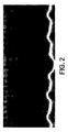
画像は、任意により、ノイズを低減するためにフィルタリングされることが可能である。フィルタリングは、3×3ガウスフィルタを使用して実行可能である。例えば、図2は、3×3ガウスフィルタ適用後のMモードデータ画像セットを示す。フィルタリングは、ガウスフィルタに限定されない。当業者に既知であるその他のノイズ低減技術は、使用可能であり、そのノイズ低減技術として、ボックスフィルタ、ローパスフィルタ、またはスペクトルフィルタなどが挙げられるがそれだけに限定されない。 The image can optionally be filtered to reduce noise. Filtering can be performed using a 3 × 3 Gaussian filter. For example, FIG. 2 shows an M-mode data image set after applying a 3 × 3 Gaussian filter. Filtering is not limited to a Gaussian filter. Other noise reduction techniques known to those skilled in the art can be used and include, but are not limited to, box filters, low pass filters, or spectral filters.
画像における特徴を識別する際に補助を所望する研究者であり得る操作者は、左心室壁の本実施例において、取得したMモード画像の関心特徴を選択することによって、その壁の追跡を開始することができる。図3は、心臓壁の底部において、操作者により選択された画素上に配置される十字を示す。本実施例において、操作者は、画像の配置および時間の両方を選択している。この配置は、操作者が追跡したい特徴、つまり、本実施例においては心臓壁の端部を表す。本実施例において、操作者により選択されたこの特徴は、画像の画素に相当する。この画素は、元々の時間点を規定し、また、今後の特徴(壁)検出のために使用可能である。 An operator who may be a researcher who wants assistance in identifying features in the image, in this example of the left ventricular wall, starts tracking the wall by selecting the feature of interest in the acquired M-mode image can do. FIG. 3 shows a cross placed on the pixel selected by the operator at the bottom of the heart wall. In this embodiment, the operator has selected both the image layout and the time. This arrangement represents the feature that the operator wants to track, in this example the end of the heart wall. In this embodiment, this feature selected by the operator corresponds to an image pixel. This pixel defines the original time point and can be used for future feature (wall) detection.
選択点の上側または下側におけるm個の画素(垂直軸または深度軸)と、選択点の右側または左側におけるn個の画素(水平軸または時間軸)は、基準領域を画定する。本基準領域の例は図4に示される。典型的には、基準領域のサイズは、約3×32画素であり、1×32または2×32などのその他のサイズも使用可能である。図4の基準領域は1×32である。 The m pixels (vertical axis or depth axis) above or below the selection point and the n pixels (horizontal axis or time axis) on the right or left side of the selection point define a reference region. An example of this reference region is shown in FIG. Typically, the size of the reference area is about 3 × 32 pixels, and other sizes such as 1 × 32 or 2 × 32 can be used. The reference area in FIG. 4 is 1 × 32.
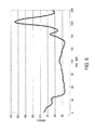
図5に示される2次元チャートは、図3に示された、操作者によって選択された画素における、垂直線(深度軸)上の画素強度の抽出である。図4に示される基準領域は、画素値160付近の陰影部分として図5において識別される。
The two-dimensional chart shown in FIG. 5 is extraction of pixel intensity on the vertical line (depth axis) in the pixel selected by the operator shown in FIG. The reference region shown in FIG. 4 is identified in FIG. 5 as a shaded portion near the
壁検出工程により、操作者によって選択された時間画素の時間点を右側(時間値増加)に選択する。刻み幅は小さく、取得パルス繰り返し周波数(画像線が取得される速度)は、約1ミリ秒から10ミリ秒である。画像画素に関し、時間点は、約1画素から100画素の間のどの画素にでも移動可能であるが、典型的には、約1画素から5画素の間の小さい刻み幅が使用される(約1ミリ秒の経過時間に相当する)。本明細書で説明される例において、時間点は、右側に移動されている。左側への移動も実行可能である。 In the wall detection process, the time point of the time pixel selected by the operator is selected on the right side (time value increase). The step size is small, and the acquisition pulse repetition frequency (speed at which the image line is acquired) is about 1 to 10 milliseconds. For image pixels, the time point can be moved to any pixel between about 1 and 100 pixels, but typically a small step size between about 1 and 5 pixels is used (about Equivalent to 1 millisecond elapsed time). In the example described herein, the time point has been moved to the right. Movement to the left is also possible.
本例において、時間点は、右側に10画素移動される。図6は、基準領域に沿った画素強度の抽出を示し、垂直線は時間点を通る。図6において、下側壁の配置が、深度点約160から深度約180に移動していることがわかる。 In this example, the time point is moved 10 pixels to the right. FIG. 6 shows the extraction of pixel intensity along the reference region, with the vertical line passing through the time point. In FIG. 6, it can be seen that the arrangement of the lower wall has moved from a depth point of about 160 to a depth of about 180.
壁の追跡は、図5の操作者により選択された基準領域と、図6の比較領域との比較に基づいている。これは、絶対差の和の最小値を使用して実行可能であり、ここで、基準データセットの画素値(画像強度)は、比較データセットの画素値(画像強度)から減算され、以下の計算を使用して差異誤差が求められる。 Wall tracking is based on a comparison of the reference region selected by the operator of FIG. 5 with the comparison region of FIG. This can be done using the minimum value of the sum of absolute differences, where the pixel value (image intensity) of the reference data set is subtracted from the pixel value (image intensity) of the comparison data set and The difference error is determined using a calculation.
本発明に関する前述の説明は、本発明の最良の形態における実現教示、つまり現時点で既知の実施形態として提供される。この目的のために、本明細書に記載の本発明の種々の側面に多くの変更を加えることが可能である一方で、依然として本発明の有益な結果を入手可能であることを、当業者は認識および理解するだろう。また、本発明の所望の利益のいくつかが、その他の特徴を利用せずに、本発明の特徴のいくつかを選択することによって入手可能であることが明白であるだろう。 The foregoing description of the invention is provided as an implementation teaching in the best mode of the invention, ie a presently known embodiment. For this purpose, those skilled in the art will appreciate that while it is possible to make many changes to the various aspects of the invention described herein, the beneficial results of the invention are still available. You will recognize and understand. It will also be apparent that some of the desired benefits of the present invention can be obtained by selecting some of the features of the present invention without utilizing other features.
本出願書において、種々の公開が参照される場合、本発明が関連する当技術分野の状態を十分に説明するために、本公開の全体における開示は、参照することによって本出願に組み込まれる。 In this application, where various publications are referenced, the entire disclosure of this publication is incorporated by reference into this application in order to fully explain the state of the art to which this invention pertains.
別途明示的に記載される場合を除き、本明細書に記載のいかなる方法または工程も、そのステップの特定の順序による実行を必要とすることを解釈するようには決して意図されない。従って、方法または工程の請求項は、そのステップが従うべき順序を実際に記載していない場合、そのステップが特定の順序に限定されることが請求項または説明に別途明示的に記載される場合を除き、いかなる場合もその順序を推測するようには決して意図されない。これは、ステップまたは動作フローの配列に関する論理事項、文法構成または句読点に由来する通常の意味、および本明細書に記載の実施形態の数または種類を含む、解釈に関する任意の潜在的な非明示的基礎も有する。 Except where expressly stated otherwise, any method or process described herein is in no way intended to be interpreted as requiring that the steps be performed in a particular order. Thus, if a method or process claim does not actually state the order in which the steps are to follow, it will be explicitly stated in the claim or description that the steps are limited to a specific order Except in any case, it is never intended to infer the order. This is any implicit implicit in terms of interpretation, including the logical meaning of the sequence of steps or operational flows, the usual meaning derived from grammatical construction or punctuation, and the number or type of embodiments described herein. It also has a foundation.
従って、本発明に対する修正および適応が可能であり、さらには、その修正および適応は特定の状況において望ましく、また、本発明の一部であることを、当業者は認識するであろう。本発明のその他の実施形態は、本明細書に開示される本発明の明細および実践を考慮することによって、当業者に明白になるであろう。従って、前述の説明は、本発明の原理を説明するものとして提供され、本発明を限定するものではない。明細および例は、単に例示的であると見なされ、本発明の真の範囲および精神は、以下の請求項によって示される。 Accordingly, those skilled in the art will recognize that modifications and adaptations to the present invention are possible, and that such modifications and adaptations are desirable in certain circumstances and are part of the present invention. Other embodiments of the invention will be apparent to those skilled in the art from consideration of the specification and practice of the invention disclosed herein. Accordingly, the foregoing description is provided as illustrative of the principles of the invention and is not intended to limit the invention. The specification and examples are to be regarded merely as illustrative and the true scope and spirit of the invention is indicated by the following claims.
Claims (52)
該Mモード超音波画像の選択された関心特徴を受信することと、
実質的に該関心特徴付近に基準領域を生成することであって、1つ以上の基準領域の強度値が該基準領域について決定される、ことと、
Mモード超音波画像において選択された時間点を受信することであって、該時間点は該関心特徴と異なる時間にある、ことと、
実質的に該時間点付近に比較領域を生成することであって、1つ以上の比較領域の強度値が該比較領域について決定される、ことと、
該基準領域の強度値と該比較領域の強度値との比較を実行することによって、差異誤差を決定することと、
該差異誤差の最小値を決定することであって、位置が該最小差異誤差について決定され、かつ、該最小差異誤差の位置は、該時間点における該関心特徴の計算された位置として識別される、ことと
を含む、方法。 A method for tracking a feature selected by a user in an M-mode ultrasound image comprising:
Receiving a selected feature of interest of the M-mode ultrasound image;
Generating a reference region substantially near the feature of interest, wherein an intensity value of one or more reference regions is determined for the reference region;
Receiving a selected time point in the M-mode ultrasound image, the time point being at a different time than the feature of interest;
Generating a comparison region substantially near the time point, wherein intensity values of one or more comparison regions are determined for the comparison region;
Determining a difference error by performing a comparison between the intensity value of the reference region and the intensity value of the comparison region;
Determining a minimum value of the difference error, wherein a position is determined for the minimum difference error, and the position of the minimum difference error is identified as the calculated position of the feature of interest at the time point. Including, and.
Mモード超音波画像を格納するデータ記録装置を有する処理ユニットと、
少なくとも一部がデータ記録装置に格納される実行可能なコードを有するプログラムモジュールであって、該処理ユニットに命令を提供するプログラムモジュールと
を備え、
該プログラムモジュールは、該処理ユニットに、
該選択された特徴の画素を該Mモード画像内で選択することと、
該選択された特徴画素付近に基準領域を生成することと、
該基準領域の画像強度値を抽出することと、
該Mモード超音波画像において時間点を選択することであって、該時間点は、該選択された特徴画素と異なる時間にある、ことと、
該選択された時間点付近に比較領域を生成すること、
該比較領域の画像強度値を抽出することと、
該基準領域の画像強度値を該比較領域の画像強度値と比較することによって、該比較領域内の位置毎に差異誤差を計算することと、
該時間点における特徴画素として、最小差異誤差を有する位置を識別することと
を該処理ユニットにさせるように構成される、装置。 An apparatus for creating a trace of a selected feature on an M-mode ultrasound image,
A processing unit having a data recording device for storing M-mode ultrasound images;
A program module having executable code stored at least in part in the data recording device, the program module providing instructions to the processing unit,
The program module is in the processing unit
Selecting pixels of the selected feature in the M-mode image;
Generating a reference region near the selected feature pixel;
Extracting an image intensity value of the reference region;
Selecting a time point in the M-mode ultrasound image, the time point being at a different time than the selected feature pixel;
Generating a comparison region near the selected time point;
Extracting an image intensity value of the comparison region;
Calculating a difference error for each position in the comparison area by comparing the image intensity value of the reference area with the image intensity value of the comparison area;
An apparatus configured to cause the processing unit to identify a position having a minimum difference error as a feature pixel at the time point.
該処理は、
該選択された特徴の画素を該Mモード画像内で選択することと、
該選択された特徴画素付近に基準領域を生成することと、
該基準領域の画像強度値を抽出することと、
該Mモード超音波画像において時間点を選択することであって、該時間点は、該選択された特徴画素と異なる時間にある、ことと、
実質的に該選択された時間点付近に比較領域を生成することであって、該比較領域の画像強度値が抽出される、ことと、
該基準領域画像の強度値を該比較領域画像の強度値と比較することによって、該比較領域内の位置毎に差異誤差を計算することと、
該Mモード画像に該追跡された特徴を提供するために、該時間点における特徴画素として、最小差異誤差を有する位置を識別することと
を含む、Mモード超音波画像。 An M-mode ultrasound image with selected feature tracking generated by processing,
The process is
Selecting pixels of the selected feature in the M-mode image;
Generating a reference region near the selected feature pixel;
Extracting an image intensity value of the reference region;
Selecting a time point in the M-mode ultrasound image, the time point being at a different time than the selected feature pixel;
Generating a comparison region substantially near the selected time point, wherein an image intensity value of the comparison region is extracted;
Calculating a difference error for each position in the comparison area by comparing the intensity value of the reference area image with the intensity value of the comparison area image;
Identifying a position having a minimum difference error as a feature pixel at the time point to provide the tracked feature to the M-mode image.
Mモード画像内で選択された特徴の選択された画素を受信するための第1の実行可能部分と、
該選択された特徴画素付近に基準領域を生成し、該基準領域の画像強度値を抽出するための第2の実行可能部分と、
該Mモード超音波画像において時間点を選択することであって、該時間点は該選択された特徴画素と異なる時間にある、ことと、該選択された時間点付近に比較領域を生成することと、該比較領域の画像強度値を抽出することとのための第3の実行可能部分と、
該基準領域の画像強度値を該比較領域の画像強度値と比較することによって、該比較領域内の位置毎に差異誤差を計算することと、該時間点における特徴画素として最小差異誤差を有する位置を識別することとのための第4の実行可能部分と
を含む、コンピュータプログラム製品。 A computer program product for creating a trace of a selected feature on an M-mode ultrasound image, the computer program product comprising at least one computer-readable storage medium having a computer-readable program code portion stored therein. And the computer readable program code portion is
A first executable portion for receiving a selected pixel of a selected feature in an M-mode image;
A second executable portion for generating a reference region near the selected feature pixel and extracting an image intensity value of the reference region;
Selecting a time point in the M-mode ultrasound image, wherein the time point is at a different time than the selected feature pixel, and generating a comparison region near the selected time point And a third executable part for extracting the image intensity value of the comparison region;
Calculating a difference error for each position in the comparison area by comparing the image intensity value of the reference area with the image intensity value of the comparison area; and a position having a minimum difference error as a feature pixel at the time point And a fourth executable part for identifying the computer program product.
Applications Claiming Priority (3)
| Application Number | Priority Date | Filing Date | Title |
|---|---|---|---|
| US77592106P | 2006-02-23 | 2006-02-23 | |
| US11/677,941 US20070196005A1 (en) | 2006-02-23 | 2007-02-22 | Feature Tracing Process for M-mode Images |
| PCT/US2007/005034 WO2007100804A2 (en) | 2006-02-23 | 2007-02-23 | Feature tracing process for m- mode images |
Publications (2)
| Publication Number | Publication Date |
|---|---|
| JP2009527336A true JP2009527336A (en) | 2009-07-30 |
| JP2009527336A5 JP2009527336A5 (en) | 2010-03-25 |
Family
ID=38428235
Family Applications (1)
| Application Number | Title | Priority Date | Filing Date |
|---|---|---|---|
| JP2008556472A Withdrawn JP2009527336A (en) | 2006-02-23 | 2007-02-23 | Feature tracking process for M-mode images |
Country Status (5)
| Country | Link |
|---|---|
| US (1) | US20070196005A1 (en) |
| EP (1) | EP1994490A4 (en) |
| JP (1) | JP2009527336A (en) |
| CA (1) | CA2643382A1 (en) |
| WO (1) | WO2007100804A2 (en) |
Cited By (1)
| Publication number | Priority date | Publication date | Assignee | Title |
|---|---|---|---|---|
| JP2015527311A (en) * | 2012-07-10 | 2015-09-17 | サウディ ベーシック インダストリーズ コーポレイション | Process for oligomerization of ethylene |
Families Citing this family (9)
| Publication number | Priority date | Publication date | Assignee | Title |
|---|---|---|---|---|
| US20100022887A1 (en) * | 2008-07-21 | 2010-01-28 | Joan Carol Main | Method for imaging intracavitary blood flow patterns |
| US8343053B2 (en) * | 2009-07-21 | 2013-01-01 | Siemens Medical Solutions Usa, Inc. | Detection of structure in ultrasound M-mode imaging |
| JP5367749B2 (en) * | 2011-03-25 | 2013-12-11 | 株式会社東芝 | Server apparatus, communication method and program |
| US9211110B2 (en) | 2013-03-15 | 2015-12-15 | The Regents Of The University Of Michigan | Lung ventillation measurements using ultrasound |
| CN105719265B (en) * | 2014-12-01 | 2018-11-02 | 安克生医股份有限公司 | The quantization method of echo feature and the ultrasonic energy bearing calibration for using echo characteristic quantification numerical value |
| CN112336378B (en) * | 2019-08-08 | 2022-05-03 | 深圳市恩普电子技术有限公司 | M-type echocardiogram processing method and system for animal ultrasonic diagnosis |
| CN110503042B (en) * | 2019-08-23 | 2022-04-19 | Oppo广东移动通信有限公司 | Image processing method and device and electronic equipment |
| US20230263501A1 (en) * | 2022-02-23 | 2023-08-24 | EchoNous, Inc. | Determining heart rate based on a sequence of ultrasound images |
| CN114463653B (en) | 2022-04-12 | 2022-06-28 | 浙江大学 | High-concentration micro-bubble shape recognition and track tracking speed measurement method |
Family Cites Families (18)
| Publication number | Priority date | Publication date | Assignee | Title |
|---|---|---|---|---|
| US5178151A (en) * | 1988-04-20 | 1993-01-12 | Sackner Marvin A | System for non-invasive detection of changes of cardiac volumes and aortic pulses |
| US5247938A (en) * | 1990-01-11 | 1993-09-28 | University Of Washington | Method and apparatus for determining the motility of a region in the human body |
| US5365269A (en) * | 1992-10-22 | 1994-11-15 | Santa Barbara Instrument Group, Inc. | Electronic camera with automatic image tracking and multi-frame registration and accumulation |
| GB2324428A (en) * | 1997-04-17 | 1998-10-21 | Sharp Kk | Image tracking; observer tracking stereoscopic display |
| US5800356A (en) * | 1997-05-29 | 1998-09-01 | Advanced Technology Laboratories, Inc. | Ultrasonic diagnostic imaging system with doppler assisted tracking of tissue motion |
| US5916168A (en) * | 1997-05-29 | 1999-06-29 | Advanced Technology Laboratories, Inc. | Three dimensional M-mode ultrasonic diagnostic imaging system |
| US20020173721A1 (en) * | 1999-08-20 | 2002-11-21 | Novasonics, Inc. | User interface for handheld imaging devices |
| EP1123687A3 (en) * | 2000-02-10 | 2004-02-04 | Aloka Co., Ltd. | Ultrasonic diagnostic apparatus |
| FI111192B (en) * | 2000-03-31 | 2003-06-13 | Oseir Oy | Method for Imaging Measurement, Imaging Measurement and Use of Measured Information in Process Control |
| WO2002071096A2 (en) * | 2001-03-02 | 2002-09-12 | Massachusetts Institute Of Technology | High-definition imaging apparatus and method |
| JP3790126B2 (en) * | 2001-05-30 | 2006-06-28 | 株式会社東芝 | Spatiotemporal domain information processing method and spatiotemporal domain information processing system |
| US20030045797A1 (en) * | 2001-08-28 | 2003-03-06 | Donald Christopher | Automatic optimization of doppler display parameters |
| ES2226602T1 (en) * | 2002-07-15 | 2005-04-01 | Baylor College Of Medicine | IDENTIFICATION PROCEDURE OF BIOLOGICALLY ACTIVE AGENTS. |
| JP4068485B2 (en) * | 2002-09-30 | 2008-03-26 | 株式会社東芝 | Image composition method, image composition apparatus, and image composition program |
| JP4185346B2 (en) * | 2002-10-18 | 2008-11-26 | 株式会社日立製作所 | Storage apparatus and configuration setting method thereof |
| EP1522875B1 (en) * | 2003-09-30 | 2012-03-21 | Esaote S.p.A. | A method of tracking position and velocity of object's borders in two or three dimensional digital echographic images |
| US20050096543A1 (en) * | 2003-11-03 | 2005-05-05 | Jackson John I. | Motion tracking for medical imaging |
| US8900149B2 (en) * | 2004-04-02 | 2014-12-02 | Teratech Corporation | Wall motion analyzer |
-
2007
- 2007-02-22 US US11/677,941 patent/US20070196005A1/en not_active Abandoned
- 2007-02-23 EP EP07751768A patent/EP1994490A4/en not_active Withdrawn
- 2007-02-23 CA CA002643382A patent/CA2643382A1/en not_active Abandoned
- 2007-02-23 WO PCT/US2007/005034 patent/WO2007100804A2/en active Application Filing
- 2007-02-23 JP JP2008556472A patent/JP2009527336A/en not_active Withdrawn
Cited By (2)
| Publication number | Priority date | Publication date | Assignee | Title |
|---|---|---|---|---|
| JP2015527311A (en) * | 2012-07-10 | 2015-09-17 | サウディ ベーシック インダストリーズ コーポレイション | Process for oligomerization of ethylene |
| US9896392B2 (en) | 2012-07-10 | 2018-02-20 | Saudi Basic Industries Corporation | Method for oligomerization of ethylene |
Also Published As
| Publication number | Publication date |
|---|---|
| WO2007100804A3 (en) | 2008-11-13 |
| EP1994490A4 (en) | 2010-09-29 |
| CA2643382A1 (en) | 2007-09-07 |
| EP1994490A2 (en) | 2008-11-26 |
| US20070196005A1 (en) | 2007-08-23 |
| WO2007100804A2 (en) | 2007-09-07 |
Similar Documents
| Publication | Publication Date | Title |
|---|---|---|
| JP5823312B2 (en) | Method of operating an ultrasound imaging system | |
| JP2009527336A (en) | Feature tracking process for M-mode images | |
| JP6640922B2 (en) | Ultrasound diagnostic device and image processing device | |
| JP4942666B2 (en) | Respiration signal synchronization method by capturing ultrasound data | |
| JP2021121354A (en) | Imaging view steering using model-based segmentation | |
| JP5015513B2 (en) | Integrated ultrasound device for measurement of anatomical structures | |
| JP2013135942A (en) | System and method for 3-d visualization of vascular structures using ultrasound | |
| CN105407807B (en) | The non-imaged two-dimensional array probe and system of automatic screening for carotid artery stenosis | |
| JP2011505951A (en) | Robot ultrasound system with fine adjustment and positioning control using a feedback responsive to the acquired image data | |
| JP5481108B2 (en) | Ultrasonic diagnostic apparatus and automatic diagnosis support apparatus | |
| DE102012108121A1 (en) | Method and system for ultrasound-assisted automatic detection, quantification and tracking of pathologies | |
| JP2005074225A (en) | Method and device for obtaining volumetric scan to periodically moving object | |
| CN109310399B (en) | Medical ultrasonic image processing apparatus | |
| JP5611546B2 (en) | Automatic diagnosis support apparatus, ultrasonic diagnosis apparatus, and automatic diagnosis support program | |
| JP2006507883A (en) | A segmentation tool to identify flow areas within an imaging system | |
| JP2021510595A (en) | Equipment and methods for obtaining anatomical measurements from ultrasound images | |
| US20220104794A1 (en) | Method and ultrasound system for shear wave elasticity imaging | |
| US11304678B2 (en) | Systems, methods, and apparatuses for confidence mapping of shear wave imaging | |
| US11944485B2 (en) | Ultrasound device, systems, and methods for lung pulse detection by plueral line movement | |
| Liu et al. | ECG triggering and gating for ultrasonic small animal imaging | |
| JP2008073423A (en) | Ultrasonic diagnostic apparatus, diagnostic parameter measuring device, and diagnostic parameter measuring method | |
| JP2016522072A (en) | Lung tissue identification in anatomically intelligent echocardiography | |
| JP2019526357A (en) | Ultrasonic diagnostic equipment | |
| CN101449279A (en) | Feature tracing process for M-mode images | |
| CN112087971A (en) | Ultrasound imaging system and method |
Legal Events
| Date | Code | Title | Description |
|---|---|---|---|
| A521 | Request for written amendment filed |
Free format text: JAPANESE INTERMEDIATE CODE: A523 Effective date: 20100202 |
|
| A621 | Written request for application examination |
Free format text: JAPANESE INTERMEDIATE CODE: A621 Effective date: 20100202 |
|
| A072 | Dismissal of procedure [no reply to invitation to correct request for examination] |
Free format text: JAPANESE INTERMEDIATE CODE: A073 Effective date: 20110615 |
|
| A300 | Application deemed to be withdrawn because no request for examination was validly filed |
Free format text: JAPANESE INTERMEDIATE CODE: A300 Effective date: 20110705 |