EP1522875B1 - A method of tracking position and velocity of object's borders in two or three dimensional digital echographic images - Google Patents
A method of tracking position and velocity of object's borders in two or three dimensional digital echographic images Download PDFInfo
- Publication number
- EP1522875B1 EP1522875B1 EP03425639A EP03425639A EP1522875B1 EP 1522875 B1 EP1522875 B1 EP 1522875B1 EP 03425639 A EP03425639 A EP 03425639A EP 03425639 A EP03425639 A EP 03425639A EP 1522875 B1 EP1522875 B1 EP 1522875B1
- Authority
- EP
- European Patent Office
- Prior art keywords
- sequence
- border
- image
- image frames
- line
- Prior art date
- Legal status (The legal status is an assumption and is not a legal conclusion. Google has not performed a legal analysis and makes no representation as to the accuracy of the status listed.)
- Expired - Lifetime
Links
Images


Classifications
-
- A—HUMAN NECESSITIES
- A61—MEDICAL OR VETERINARY SCIENCE; HYGIENE
- A61B—DIAGNOSIS; SURGERY; IDENTIFICATION
- A61B8/00—Diagnosis using ultrasonic, sonic or infrasonic waves
- A61B8/08—Clinical applications
- A61B8/0883—Clinical applications for diagnosis of the heart
-
- A—HUMAN NECESSITIES
- A61—MEDICAL OR VETERINARY SCIENCE; HYGIENE
- A61B—DIAGNOSIS; SURGERY; IDENTIFICATION
- A61B8/00—Diagnosis using ultrasonic, sonic or infrasonic waves
- A61B8/08—Clinical applications
-
- G—PHYSICS
- G01—MEASURING; TESTING
- G01S—RADIO DIRECTION-FINDING; RADIO NAVIGATION; DETERMINING DISTANCE OR VELOCITY BY USE OF RADIO WAVES; LOCATING OR PRESENCE-DETECTING BY USE OF THE REFLECTION OR RERADIATION OF RADIO WAVES; ANALOGOUS ARRANGEMENTS USING OTHER WAVES
- G01S15/00—Systems using the reflection or reradiation of acoustic waves, e.g. sonar systems
- G01S15/88—Sonar systems specially adapted for specific applications
- G01S15/89—Sonar systems specially adapted for specific applications for mapping or imaging
- G01S15/8906—Short-range imaging systems; Acoustic microscope systems using pulse-echo techniques
- G01S15/8979—Combined Doppler and pulse-echo imaging systems
- G01S15/8981—Discriminating between fixed and moving objects or between objects moving at different speeds, e.g. wall clutter filter
-
- G—PHYSICS
- G01—MEASURING; TESTING
- G01S—RADIO DIRECTION-FINDING; RADIO NAVIGATION; DETERMINING DISTANCE OR VELOCITY BY USE OF RADIO WAVES; LOCATING OR PRESENCE-DETECTING BY USE OF THE REFLECTION OR RERADIATION OF RADIO WAVES; ANALOGOUS ARRANGEMENTS USING OTHER WAVES
- G01S7/00—Details of systems according to groups G01S13/00, G01S15/00, G01S17/00
- G01S7/52—Details of systems according to groups G01S13/00, G01S15/00, G01S17/00 of systems according to group G01S15/00
- G01S7/52017—Details of systems according to groups G01S13/00, G01S15/00, G01S17/00 of systems according to group G01S15/00 particularly adapted to short-range imaging
- G01S7/52023—Details of receivers
- G01S7/52036—Details of receivers using analysis of echo signal for target characterisation
-
- G—PHYSICS
- G01—MEASURING; TESTING
- G01S—RADIO DIRECTION-FINDING; RADIO NAVIGATION; DETERMINING DISTANCE OR VELOCITY BY USE OF RADIO WAVES; LOCATING OR PRESENCE-DETECTING BY USE OF THE REFLECTION OR RERADIATION OF RADIO WAVES; ANALOGOUS ARRANGEMENTS USING OTHER WAVES
- G01S7/00—Details of systems according to groups G01S13/00, G01S15/00, G01S17/00
- G01S7/52—Details of systems according to groups G01S13/00, G01S15/00, G01S17/00 of systems according to group G01S15/00
- G01S7/52017—Details of systems according to groups G01S13/00, G01S15/00, G01S17/00 of systems according to group G01S15/00 particularly adapted to short-range imaging
- G01S7/52046—Techniques for image enhancement involving transmitter or receiver
-
- G—PHYSICS
- G01—MEASURING; TESTING
- G01S—RADIO DIRECTION-FINDING; RADIO NAVIGATION; DETERMINING DISTANCE OR VELOCITY BY USE OF RADIO WAVES; LOCATING OR PRESENCE-DETECTING BY USE OF THE REFLECTION OR RERADIATION OF RADIO WAVES; ANALOGOUS ARRANGEMENTS USING OTHER WAVES
- G01S7/00—Details of systems according to groups G01S13/00, G01S15/00, G01S17/00
- G01S7/52—Details of systems according to groups G01S13/00, G01S15/00, G01S17/00 of systems according to group G01S15/00
- G01S7/52017—Details of systems according to groups G01S13/00, G01S15/00, G01S17/00 of systems according to group G01S15/00 particularly adapted to short-range imaging
- G01S7/52053—Display arrangements
- G01S7/52057—Cathode ray tube displays
- G01S7/5206—Two-dimensional coordinated display of distance and direction; B-scan display
- G01S7/52063—Sector scan display
-
- G—PHYSICS
- G06—COMPUTING OR CALCULATING; COUNTING
- G06T—IMAGE DATA PROCESSING OR GENERATION, IN GENERAL
- G06T7/00—Image analysis
- G06T7/0002—Inspection of images, e.g. flaw detection
- G06T7/0012—Biomedical image inspection
-
- G—PHYSICS
- G06—COMPUTING OR CALCULATING; COUNTING
- G06T—IMAGE DATA PROCESSING OR GENERATION, IN GENERAL
- G06T7/00—Image analysis
- G06T7/10—Segmentation; Edge detection
- G06T7/12—Edge-based segmentation
-
- G—PHYSICS
- G06—COMPUTING OR CALCULATING; COUNTING
- G06T—IMAGE DATA PROCESSING OR GENERATION, IN GENERAL
- G06T7/00—Image analysis
- G06T7/20—Analysis of motion
- G06T7/246—Analysis of motion using feature-based methods, e.g. the tracking of corners or segments
- G06T7/251—Analysis of motion using feature-based methods, e.g. the tracking of corners or segments involving models
-
- A—HUMAN NECESSITIES
- A61—MEDICAL OR VETERINARY SCIENCE; HYGIENE
- A61B—DIAGNOSIS; SURGERY; IDENTIFICATION
- A61B8/00—Diagnosis using ultrasonic, sonic or infrasonic waves
- A61B8/08—Clinical applications
- A61B8/0891—Clinical applications for diagnosis of blood vessels
-
- A—HUMAN NECESSITIES
- A61—MEDICAL OR VETERINARY SCIENCE; HYGIENE
- A61B—DIAGNOSIS; SURGERY; IDENTIFICATION
- A61B8/00—Diagnosis using ultrasonic, sonic or infrasonic waves
- A61B8/48—Diagnostic techniques
- A61B8/485—Diagnostic techniques involving measuring strain or elastic properties
-
- A—HUMAN NECESSITIES
- A61—MEDICAL OR VETERINARY SCIENCE; HYGIENE
- A61B—DIAGNOSIS; SURGERY; IDENTIFICATION
- A61B8/00—Diagnosis using ultrasonic, sonic or infrasonic waves
- A61B8/48—Diagnostic techniques
- A61B8/486—Diagnostic techniques involving arbitrary m-mode
-
- G—PHYSICS
- G01—MEASURING; TESTING
- G01S—RADIO DIRECTION-FINDING; RADIO NAVIGATION; DETERMINING DISTANCE OR VELOCITY BY USE OF RADIO WAVES; LOCATING OR PRESENCE-DETECTING BY USE OF THE REFLECTION OR RERADIATION OF RADIO WAVES; ANALOGOUS ARRANGEMENTS USING OTHER WAVES
- G01S15/00—Systems using the reflection or reradiation of acoustic waves, e.g. sonar systems
- G01S15/88—Sonar systems specially adapted for specific applications
- G01S15/89—Sonar systems specially adapted for specific applications for mapping or imaging
- G01S15/8906—Short-range imaging systems; Acoustic microscope systems using pulse-echo techniques
- G01S15/8993—Three dimensional imaging systems
-
- G—PHYSICS
- G01—MEASURING; TESTING
- G01S—RADIO DIRECTION-FINDING; RADIO NAVIGATION; DETERMINING DISTANCE OR VELOCITY BY USE OF RADIO WAVES; LOCATING OR PRESENCE-DETECTING BY USE OF THE REFLECTION OR RERADIATION OF RADIO WAVES; ANALOGOUS ARRANGEMENTS USING OTHER WAVES
- G01S7/00—Details of systems according to groups G01S13/00, G01S15/00, G01S17/00
- G01S7/52—Details of systems according to groups G01S13/00, G01S15/00, G01S17/00 of systems according to group G01S15/00
- G01S7/52017—Details of systems according to groups G01S13/00, G01S15/00, G01S17/00 of systems according to group G01S15/00 particularly adapted to short-range imaging
- G01S7/52053—Display arrangements
- G01S7/52057—Cathode ray tube displays
- G01S7/52068—Stereoscopic displays; Three-dimensional displays; Pseudo 3D displays
- G01S7/52069—Grey-scale displays
-
- G—PHYSICS
- G06—COMPUTING OR CALCULATING; COUNTING
- G06T—IMAGE DATA PROCESSING OR GENERATION, IN GENERAL
- G06T2207/00—Indexing scheme for image analysis or image enhancement
- G06T2207/10—Image acquisition modality
- G06T2207/10016—Video; Image sequence
-
- G—PHYSICS
- G06—COMPUTING OR CALCULATING; COUNTING
- G06T—IMAGE DATA PROCESSING OR GENERATION, IN GENERAL
- G06T2207/00—Indexing scheme for image analysis or image enhancement
- G06T2207/10—Image acquisition modality
- G06T2207/10132—Ultrasound image
-
- G—PHYSICS
- G06—COMPUTING OR CALCULATING; COUNTING
- G06T—IMAGE DATA PROCESSING OR GENERATION, IN GENERAL
- G06T2207/00—Indexing scheme for image analysis or image enhancement
- G06T2207/30—Subject of image; Context of image processing
- G06T2207/30004—Biomedical image processing
- G06T2207/30048—Heart; Cardiac
Definitions
- the invention relates to a method of tracking position and velocity of objects' borders in two or three dimensional digital echographic images comprising the combination of features according to the preamble of claim 1.
- a typical example is given by echocardiography in the imaging of the left ventricle.
- the possibility of an automatic detection of the endocardial border would give objective measurement of the ventricular volume, in particular its extreme values (at proto-systole and tele-diastole) are commonly used for clinical diagnosis and the relative diagnostic indexed are calculated.
- the possibility to visualize the border velocities allows an easier assessment of the regional dynamical properties.
- borders are drawn manually by the operator over the physiologically relevant frames of a sequence of images.
- strain rate analysis method in ultrasonic diagnostic imaging is disclosed in WO 02/45587 .
- strain rate analysis is performed for ultrasonic images in which the spatial gradient of velocity is calculated in the direction of tissue motion.
- Strain rate is calculated for cardiac ultrasound images in the direction of motion which, for myocardial images, may be either in the plane of the myocardium or across the myocardium.
- Strain rate information is calculated for a sequence of images of a heart cycle and displayed for an automatically drawn border such as the endocardial border over the full heart cycle.
- the spatial gradient of velocity used for determining the strain and the displacements of the borders form one frame to a successive one in a sequence of frames uses so called Doppler Tissue Imaging, so called DTI.
- This technique allows to measure tissue velocity over all points in the ventricular wall.
- the measurement of velocity itself provides a direct information about the wall motion and helps to uncover abnormalities not immediately observable from the visualization in B-mode.
- the velocity contains information about either rigid body displacement, shear, and contraction/distension, the latter being immediately related to the myocardial activity.
- Post processing of the DTI velocity data allows the evaluation of additional quantities, namely strain-rate and strain, that are strictly related to the regional function. Segmental strain gives a direct evaluation of the degree of contractility of the myocardium during systole, as well as of its relaxation during ventricular filling.
- DTI suffers from a few drawbacks consisting in limitations of the technique.
- a Doppler signal requires additional processing with respect to the simple echo.
- Doppler tissue imaging suffers further of an intrinsic limitation due to the fact that only the component of velocity along a scanline can be measured. This limitation has several drawbacks.
- the Doppler velocity does not reflect the effective tissue kinematics. Only the component of strain and strain rate along the scanline can be evaluated correctly, giving a reduced view of the local deformation state. This limits the application of DTI to the anatomic sites that can be imagined aligned along a scanline. In echocardiography this corresponds essentially to the interventricular septum and to the lateral walls in apical view.
- Document W02003/071950 discloses a method according to the preamble of claim 1.
- An object of the present invention is to provide for a method of tracking position and velocity of objects' borders in two or three dimensional digital echographic images which overcomes the drawbacks of the known tracking methods in reducing the load actually needed for acquiring the usable ultrasound image data and for evaluating, i.e. elaborating the said ultrasound imaging data in order to track the displacement of a border of a moving tissue or a moving object in a sequence of consecutive ultrasound image frames.
- Another object of the present invention is to provide for a method which can lead to more reliable results in tracking the borders of a moving tissue or object on a sequence of consecutive ultrasound image frames.
- the present invention achieves the above mentioned aims with a method of tracking position and velocity of objects' borders in two or three dimensional digital echographic images comprising the combination of steps of the preamble of claim 1 with the steps of the characterizing part of claim 1.
- More precisely transmural cuts consist in defining a line which crosses the border line drawn and passing through one reference point.
- a physiologically appropriate direction can be chosen, which typically can be the orthogonal direction to the border line at the reference point.
- This operation is made for each image frame of the sequence of frames and for each reference point chosen.
- the pixels taken along each transmural line in each of the image frames of the sequence of image frames are placed in columns, each column corresponding to one frame of the sequence of images. In this way the evolution along a transmural cut, can be represented for all instants at once in a two-dimensional space time representation.
- the above disclosed procedure is a reduction of a two dimensional problem applied to a two dimensional image such as a B-mode ultrasound image to a one dimensional problem as a M-mode image.
- the tracking of the border. i.e. of the trace of pixels is carried out along the space-time image using a cross-correlation procedure of the pixel column in the space-time image corresponding to a first image frame with the pixel column in the space-time image corresponding to a successive image frame of the sequence of image frames.
- This technique can be applied to any kind of images in which the geometry of the border line drawn does not require any kind of special reference points to be tracked a priori such as pro example closed border lines as the border line of the cavity of a blood vessel in a cross-section image of the vessel.
- a preventive cycle must be carried out for optimally tracking the border-line of the object along the sequence of image frames.
- the general topology of the border line of the object imaged can be represented by tracking the motion of these few representative points prior to carry out the tracking of at least one or some of the reference points lying on the manually or automatically drawn border-line in each frame of the sequence of image frames.
- These representative points can be for example the starting and ending points of the border line when this is an open one.
- the representative reference points of the border of an imaged object can be also suggested by the physiology when the imaged object is a particular tissue or organ, such as for example the left ventricle.
- This few representative reference points is carried out in a identical way as the one disclosed above for the other reference points on the border-line drawn manually or automatically on the first frame by using the method of transmural cuts for constructing space-time images of each of the few representative reference points and determining the displacement of these points in each of the frames of the sequence of image frames by means of cross-correlation between each of the pixel columns with the successive pixel column corresponding to the pixels along the transmural cut across the same representative point in the different image frames of the sequence of image frames.
- the direction of the transmural cuts can be chosen as the orthogonal direction
- the position and the displacement of the other reference points on the border-lines at each image frame of the sequence of image frames are obtained by rescaling the originally drawn border-line in the first image frame in such a way to obtain in each image frame corresponding to a successive instant a topologically equivalent border line geometry with respect to the original border line. Typically this results in a translation of all points along the original border line.
- This preliminary rescaling allows to keep the representative reference points always in the proper position in all frames of the sequence of image frames by rearranging the other reference points so that the representative reference points maintains the same meaning relatively to the object in all frames of the sequence of image frames.
- the space-time representation along the transmural cuts can be built using a line for the transmural cut with a thickness larger than that of a single pixel and by extracting the average value across such a thickness.
- the above mentioned method can be further developed for carrying out a surface border tracking three dimensional imaging.
- the method according to the said development comprises the following steps:
- one or more further principal section planes can be defined along each of which further section planes the methods steps 1) to o) are carried out.
- two orthogonal principal section planes are chosen for carrying out the above mentioned method steps, the crossing line of the two principal section planes defining a preferred direction of the said planes.
- the said direction can be chosen as suggested by the topological or functional feature of the object imaged.
- this physiologically relevant direction can be chosen as the cut across a central vertical plane such as the ventricle axis.
- the method according to the present invention comprises the steps of defining bounds or limits for a distance range within which the share of the said secondary section planes is defined.
- a topological or physiological relevant direction is chosen, particularly the same direction defined for determining the principal section planes, along which direction bounds are determined for the ends of a distance range within which the share of secondary section planes at least transversal, particularly perpendicular to the said relevant direction is determined.
- this one is determined as a physiologically relevant line passing through the reliable points.
- the correct border is determined along a sequence of two dimensional or three dimensional ultrasound image data and the correct border for each image frame can be displayed overlaid on the displayed image frame as an highlighted line characterized by a color which is different from the grey-scale B-mode image displayed.
- a different evaluation of the velocity vector can be obtained by applying two dimensional-correlation techniques or a specific optical flow technique particularly developed for ultrasound image data of moving objects.
- the said velocity estimation method can be carried out in combination with the above disclosed method for tracking the border of the imaged moving object.
- the said method is an adaptation of known method so called OPTICAL FLOW methods, like a known method so called PIV method used in fluid dynamics.
- the border tracked can be drawn as a line as disclosed above and the velocity vectors of the border taken at certain number of points of the said border line are displayed as arrows having a different color as the border line and the direction of the velocity vector and a length corresponding to the modulus of the velocity vector in the image plane of the two dimensional image displayed.
- the original trace is followed in time by searching the maximum likelihood over its neighborhood in the following frames.
- the tracking technique for each single point is approached using a method based on transmural cuts that is similar to that introduced in the document PCT/IT02/00114 filed on 27.02.2002. Afterward the velocity on the tracked borders are estimated on the basis of the same maximum likelihood between two consecutive frames.
- the automatic tracking method disclosed here allows the tracking of a border on a sequence of two-dimensional or three-dimensional images, and the evaluation of the velocity vector field on such borders.
- the border could be tracked on the basis of the velocity vector only, however a tracking procedure is a result of the summation (time integration) of the estimated velocities and is prone to an error growth in presence of small incorrect estimates.
- This approach reduces the two- or three-dimensional tracking to a combination of one-dimensional tracking problems along the single topological relevant direction (typically the orthogonal to the border), that can be much better controlled and made accurate.
- the accurate tracking result is employed to improve the estimates of the velocity vector.
- the result of this procedure is the automatic definition of the borders displacement and velocity over all frames of a 'sequence of images, starting from the border traced on a single image.
- the found borders information will be used to evaluated some geometric properties, like volume, area, or sizes, of the organ.
- the border kinematics tilt + velocity
- the method steps according to the present invention are firstly describe with reference to a two dimensional case.
- a sequence of two dimensional B-mode image frames is acquired.
- the frames are acquired at predetermined time interval one form the other.
- the method according to the present invention comprises a first step which consist in tracing the border over one single frame by defining a border line.
- a border is traced, manually or by another manual or automatic procedure, over one arbitrary frame.
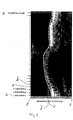
- Figure 1 illustrates an image of the left ventricle where the endocardial border points are traced from one side of the mitral annulus to the other side of the same mitral annulus.
- Figure 2 illustrates an example in which the border is a closed one where the Nth point connects to the first one.
- the method according to the invention provides for a second step of tracking the most representative reference point of the border line drawn in the first image frame.
- the general topology of the object border is reproduced on all the images by tracking the motion of a few representative points. These are commonly the starting and final points of the border when this is an open one. In specific cases additional reference points can be added to improve the first evaluation of the region about which the border must be sought.
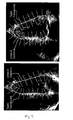
- Figure 3 shows the reference points for a left ventricle (in long axis view) that are the starting and final points of the originally traced border.
- the physiology suggests to track the motion of these points in the direction instantaneously orthogonal to the mitral plane (that is defined by these points).
- the tracking along a specified direction is performed by using the method of transmural cuts as follow.
- a line crossing the wall, passing through the point, and directed along the physiologically appropriate direction is drawn; in the case shown in figure 3 the appropriate direction is orthogonal to the mitral plane.
- two orthogonal direction can be employed.
- the pixels taken along the chosen direction line(s) are placed in columns, each column corresponding to one frame of the sequence of images.
- the evolution along a line can be represented for all instants at once in a two dimensional space-time representation (sometime referred as M-mode representation) where one axis is the distance along the line and the other axis is the time.
- M-mode representation two dimensional space-time representation
- the space time representation can be built using a line for the transmural cut with a thickness larger than that of a single pixel and extracting the average value across such a thickness. The border tracking is then performed along the space-time image.
- the tracking procedure is a procedure for following a border along one direction in a two-dimensional image like that in figure 4 starting from a known position at one instant.
- the displacement from the known point yk to the point yk+1 can be estimated by evaluating the cross-correlation between the entire column at xk with the entire column at xk+1.
- the first estimate is improved by applying the same procedure recursively on increasingly reduced spatial width about the previously found border.
- This first estimate yi can be further improved.
- a subset of the image is extracted by taking a few points above and below the first estimate yi, and a new image whose center corresponds to the sequence yi is generated.
- a snake procedure like the one described in Blake A., Yuille A. Active Vision MIT press, 1992., is employed to follow, in the new image, the image brightness level that passes through the fixed point yk.
- the tracking technique is a unique procedure that is common to different steps of the method according to the present invention.
- the result of this preliminary tracking procedure is the position and displacement, at all instants, of the most representative reference points along the predefined direction, or the vector combination when two directions are employed.
- This preliminary rescaling procedure permits to keep the reference points always at the proper position in all the frames, and to rearrange the other points so that the reference maintains the same meaning in all the frames.
- the present step of tracking the most representative reference points such as the starting and ending point of a border line can be avoided when the specific geometry does not require or have any representative reference point to be tracked a priori.
- This step can be avoided is given by the closed geometry in figure 2 .
- the method according to the invention provides for a further step consisting in the tracking of all the other reference point on the border line drawn manually or automatically in the first step on a first two dimensional image frame of the sequence of image frames.
- the tracking along a specified direction is performed by using the method of transmural cuts as follow.
- a line crossing the wall, passing through the point, and directed along the physiologically appropriate direction is drawn, this operation is made for each instant/frame of the sequence of image frames because the points are not fixed in time but they have been previously rescaled at each instant accordingly with the instantaneous displacement of the reference points.
- the appropriate direction is taken at each instant as orthogonal to the rescaled border.
- the pixels taken along each transmural line are placed in columns, each column corresponding to one frame of the sequence of images. In this way the evolution along a transmural cut, that is not fixed in all frames time but is slightly modified accordingly to the rescaling, can be represented for all instants at once in a two-dimensional space time representation analogous to that shown in figure 4 .
- the space time representation can be built using a line for the transmural cut with a thickness larger than that of a single pixel and extracting the average value across such a thickness.
- the border tracking is then performed along the space-time image using the same technique employed in the step of tracking the representative reference points and disclosed above in a detailed manner.
- the result of this step is the position, at all instants, of all the points along the predefined direction, or the vector combination when two directions are employed.
- all the original points have been tracked in time, each one independently, and we have a new border tracked over all frames.
- the method according to the present invention can be provided in combination with a procedure for determining the instant border line velocity vector for each one of the reference pints defined on the border line as tracked on each two dimensional frame.
- the velocity vector can be known when two direction (three for three-dimensional imagin) are employed for displacing it.
- the complete velocity vector can be evaluated by selecting additional direction for the transmural cuts on the already displaced point and evaluating the velocity along the additional direction.
- the space time representation can be built using a line for the transmural cut with a thickness larger than that of a single pixel and extracting the average value across such a thickness.
- the complete velocity vector can be evaluated by a two-dimensional correlation technique or a specific optical flow technique adapted to the particular case of ultrasound imaging B-mode data.
- the two-dimensional result can then be improved by imposing its accordance with the previous estimate obtained for one component from the transmural cut approach. Results of the entire procedure are shown, for one frame, in figure 1 and 2 .
- a sequence of three-dimensional (3D) datasets is mathematically a four-dimensional (4D) information that is 3D in space and 1D in time.
- the images contain one organ/object or part of it, that changes its position and shape in time, of which organ it is desired to trace the border at all instants, the border now being a sequence of two-dimensional surfaces.
- the method according to the present invention provides to choose one principal section plane which cuts to the three-dimensional dataset, and to apply the entire two-dimensional technique disclosed above on such plane.
- the principal section plane of the 3D dataset is one plane, preferably along a physiologically relevant direction. Cutting the 3D datasets of the sequence of 3D datasets with this plane furnishes one sequence of 2D images.
- Figure 6 illustrates the cutting of a three-dimensional data set of ultrasound image data of the object 0 with two orthogonal principal section planes 1 and 2 oriented in the vertical direction.
- the above steps can be repeated with more than one or two principal section planes to improve the reliability of following steps in poor quality images.
- a further step is carried out consisting in defining secondary section planes to the three-dimensional dataset, and applying the two-dimensional technique on single frames substituting the time direction with one spatial direction.
- the previous step allows to define the bounds of the surface border. For this, one direction is chosen over the plane cut used in the previous step, preferably a physiologically relevant one (like the ventricle axis), and, for each instant, evaluate the upper and lower bounds along such direction of the border found in the previous step.
- the range between these limits, at each instant, is further divided in M internal points, and the 3D dataset is cut in correspondence of such M points, with M secondary section planes that are orthogonal to the chosen direction as indicated with 3, 4, 5 in figure 7 .
- M secondary section planes that are orthogonal to the chosen direction as indicated with 3, 4, 5 in figure 7 .
- a reliable border in one single frame is defined, commonly the same frame used when the borders are drawn manually during the previous step relative to the principal section planes.
- the border now contains one or more reliable points, at the intersection with the principal section plane or planes 1, 2 and that come from the border(s) determined in the previous step relative to the principal section planes as illustrated in fig. 8 and indicated by R1, R2, R3, R4.
- a first guess border is constructed as a physiological relevant one passing through these reliable points R1, R2, R3, R4.
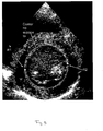
- An example of the said guess border on a secondary section plane is illustrated in the example of figure 9 .
- the two dimensional image on a secondary section plane is illustrated together with the two reliable points R1 and R2.
- the guess border passing through the said two reliable points R1 and R2 is given by given by a circle in the transversal images of the left ventricle.
- a new border is now detected by the same procedure used for a single transmural cut as disclosed in the previous chapter for the two dimensional case, this time however, substituting the time coordinate with the spatial coordinate along such first guess border as follows. Make a number of transmural cuts on the single image along the guess border, place the pixel found along each cut side by side in a new two-dimensional image and obtain a new image, like that in figure 4 , where the horizontal axis does not indicate the time coordinate but the spatial coordinate along the tentative border. As a result the correct border is tracked in one frame for each of the M sequences.
- the instantaneous velocity vector for a certain number of predefined points on the border surface can be calculated by using the same technique disclosed of the two dimensional case.
- the two dimensional technique disclosed above is used here by substituting the two dimensional estimate with a three-dimensional estimate of velocity.
- this is done by using a three-dimensional correlation or optical flow technique, in place of the two-dimensional one for evaluating the three-dimensional velocity vector.
Landscapes
- Engineering & Computer Science (AREA)
- Physics & Mathematics (AREA)
- Health & Medical Sciences (AREA)
- General Physics & Mathematics (AREA)
- Life Sciences & Earth Sciences (AREA)
- Remote Sensing (AREA)
- Radar, Positioning & Navigation (AREA)
- Computer Networks & Wireless Communication (AREA)
- General Health & Medical Sciences (AREA)
- Computer Vision & Pattern Recognition (AREA)
- Medical Informatics (AREA)
- Nuclear Medicine, Radiotherapy & Molecular Imaging (AREA)
- Theoretical Computer Science (AREA)
- Radiology & Medical Imaging (AREA)
- Biomedical Technology (AREA)
- Biophysics (AREA)
- Veterinary Medicine (AREA)
- Acoustics & Sound (AREA)
- Heart & Thoracic Surgery (AREA)
- Animal Behavior & Ethology (AREA)
- Surgery (AREA)
- Public Health (AREA)
- Pathology (AREA)
- Molecular Biology (AREA)
- Quality & Reliability (AREA)
- Multimedia (AREA)
- Cardiology (AREA)
- Ultra Sonic Daignosis Equipment (AREA)
- Image Analysis (AREA)
Abstract
Description
- The invention relates to a method of tracking position and velocity of objects' borders in two or three dimensional digital echographic images comprising the combination of features according to the preamble of
claim 1. - The automatic detection of borders and their rate of displacement is a fundamental topic in image analysis. The ability to automatically detect borders and their velocity, allows an easy recognition of objects, the improved understanding of its function. In medical imaging the automatic recognition of an organ would eventually facilitate the extraction of objective measurements and automate some diagnostic processes.
- A typical example is given by echocardiography in the imaging of the left ventricle. The possibility of an automatic detection of the endocardial border would give objective measurement of the ventricular volume, in particular its extreme values (at proto-systole and tele-diastole) are commonly used for clinical diagnosis and the relative diagnostic indexed are calculated. In addition, the possibility to visualize the border velocities allows an easier assessment of the regional dynamical properties.
- In general, and certainly in echographic imaging, the development of reliable methods for the automatic border detection is an extremely difficult task that has not received a generally reliable solution. In fact, in clinical practice, borders are drawn manually by the operator over the physiologically relevant frames of a sequence of images.
- A strain rate analysis method in ultrasonic diagnostic imaging is disclosed in
WO 02/45587 - Nevertheless DTI suffers from a few drawbacks consisting in limitations of the technique. The evaluation of velocity, and to a greater degree when rate and strain are evaluated, requires a higher frame rate with respect to B-mode imaging because velocity is a more rapidly varying function than B-mode displacement. A Doppler signal requires additional processing with respect to the simple echo.
- Doppler tissue imaging suffers further of an intrinsic limitation due to the fact that only the component of velocity along a scanline can be measured. This limitation has several drawbacks. When tissue moves in a direction that is not aligned with the scanline, the Doppler velocity does not reflect the effective tissue kinematics. Only the component of strain and strain rate along the scanline can be evaluated correctly, giving a reduced view of the local deformation state. This limits the application of DTI to the anatomic sites that can be imagined aligned along a scanline. In echocardiography this corresponds essentially to the interventricular septum and to the lateral walls in apical view.
- Document
W02003/071950 discloses a method according to the preamble ofclaim 1. - An object of the present invention is to provide for a method of tracking position and velocity of objects' borders in two or three dimensional digital echographic images which overcomes the drawbacks of the known tracking methods in reducing the load actually needed for acquiring the usable ultrasound image data and for evaluating, i.e. elaborating the said ultrasound imaging data in order to track the displacement of a border of a moving tissue or a moving object in a sequence of consecutive ultrasound image frames.
- Another object of the present invention is to provide for a method which can lead to more reliable results in tracking the borders of a moving tissue or object on a sequence of consecutive ultrasound image frames.
- The present invention achieves the above mentioned aims with a method of tracking position and velocity of objects' borders in two or three dimensional digital echographic images comprising the combination of steps of the preamble of
claim 1 with the steps of the characterizing part ofclaim 1. - More precisely transmural cuts consist in defining a line which crosses the border line drawn and passing through one reference point. A physiologically appropriate direction can be chosen, which typically can be the orthogonal direction to the border line at the reference point.
- This operation is made for each image frame of the sequence of frames and for each reference point chosen. The pixels taken along each transmural line in each of the image frames of the sequence of image frames are placed in columns, each column corresponding to one frame of the sequence of images. In this way the evolution along a transmural cut, can be represented for all instants at once in a two-dimensional space time representation.
- The above disclosed procedure is a reduction of a two dimensional problem applied to a two dimensional image such as a B-mode ultrasound image to a one dimensional problem as a M-mode image.
- The tracking of the border. i.e. of the trace of pixels is carried out along the space-time image using a cross-correlation procedure of the pixel column in the space-time image corresponding to a first image frame with the pixel column in the space-time image corresponding to a successive image frame of the sequence of image frames.
- This technique can be applied to any kind of images in which the geometry of the border line drawn does not require any kind of special reference points to be tracked a priori such as pro example closed border lines as the border line of the cavity of a blood vessel in a cross-section image of the vessel.
- When the object imaged has particular starting and ending points of a border which has a relevance as particular reference points in the motion executed by the border-line of the object, for example in the case of the walls of the endoventricular cavity, then a preventive cycle must be carried out for optimally tracking the border-line of the object along the sequence of image frames.
- According to a further improvement of the above mentioned method when the object has few very representative points the general topology of the border line of the object imaged can be represented by tracking the motion of these few representative points prior to carry out the tracking of at least one or some of the reference points lying on the manually or automatically drawn border-line in each frame of the sequence of image frames.
- These representative points can be for example the starting and ending points of the border line when this is an open one.
- The representative reference points of the border of an imaged object can be also suggested by the physiology when the imaged object is a particular tissue or organ, such as for example the left ventricle.
- Thus prior to carry out the tracking of some or all of the reference points chosen on the manually or automatically drawn border-line of the imaged object along the sequence of image frames the tracking of this few representative reference points is carried out.
- The tracking of this few representative reference points is carried out in a identical way as the one disclosed above for the other reference points on the border-line drawn manually or automatically on the first frame by using the method of transmural cuts for constructing space-time images of each of the few representative reference points and determining the displacement of these points in each of the frames of the sequence of image frames by means of cross-correlation between each of the pixel columns with the successive pixel column corresponding to the pixels along the transmural cut across the same representative point in the different image frames of the sequence of image frames.
- The direction of the transmural cuts can be chosen as the orthogonal direction
- According to a further feature after having determined the displacement of the few representative reference points on the border-line of the imaged object in some or in all of the frames of the sequence of image frames, the position and the displacement of the other reference points on the border-lines at each image frame of the sequence of image frames are obtained by rescaling the originally drawn border-line in the first image frame in such a way to obtain in each image frame corresponding to a successive instant a topologically equivalent border line geometry with respect to the original border line. Typically this results in a translation of all points along the original border line.
- This preliminary rescaling allows to keep the representative reference points always in the proper position in all frames of the sequence of image frames by rearranging the other reference points so that the representative reference points maintains the same meaning relatively to the object in all frames of the sequence of image frames.
- Thus in a preferred embodiment the complete method according to the invention comprises the following steps:
- a) Acquiring a sequence of at least two consecutive ultrasound image frames of a moving tissue or a moving object which ultrasound image frames are timely separated by a certain time interval;
- b) Tracing a border line over one single first frame either manually or with the help of an automatic border drawing algorithm;
- c) Tracking the position displacements of one or more eventually present representative reference points over the entire sequence of consecutive image frames;
- d) Rescaling the border line drawn on the first image frame at least for some or for each of the following image frames of the sequence of image frames according to the corresponding position tracked of the representative reference points;
- e) Defining a certain number of further reference points distributed along the border line on the first image frame and falling on the said border line;
- f) Tracking the position of each point independently from the others along the sequence of image frames;
- g) Tracking of the position of the representative reference points and of the other reference points being carried out by
- h) for each point independently and in each of the image frames of the sequence of image frames defining a transmural cut line consisting in a line which crosses the border line drawn and passing through the said reference point;
- i) the pixels taken along each transmural cut line in each of the image frames of the sequence of image frames are placed in columns, each column corresponding to one frame of the sequence of images for representing the evolution along a transmural cut line, for all instants at once in a two-dimensional space time representation;
- j) the tracking of the border. i.e. of the trace of pixels along each transmural cut line is carried out along the space-time image using a cross-correlation procedure of the pixel column in the space-time image corresponding to a first image frame with the pixel column in the space-time image corresponding to a successive image frame of the sequence of image frames.
- According to an improvement in both cases disclosed above when images are poor with a low signal-to-noise ratio the space-time representation along the transmural cuts can be built using a line for the transmural cut with a thickness larger than that of a single pixel and by extracting the average value across such a thickness.
- The above mentioned method can be further developed for carrying out a surface border tracking three dimensional imaging.
- The method according to the said development comprises the following steps:
- 1) Acquiring a sequence of three-dimensional ultrasound imaging data sets, each three-dimensional data set being acquired with a predetermined time interval from the previous one;
- m) Defining at least a principal section plane of each three dimensional data set along one chosen direction for obtaining a sequence of two dimensional image frames along the said section plane;
- n) Drawing a border line of the object imaged either manually or automatically on the first two dimensional image frame of the sequence of two dimensional image frames taken along the said section plane;
- o) Carrying out the tracking steps c) to j) previously disclosed for the two dimensional sequence of image frames;
- p) For each three dimensional data set of the sequence of three dimensional datasets defining a preestablished number of further secondary section planes crossing the at least one, preferably all the principal section planes, the said secondary section planes being spaced apart one from the other along a predetermined direction and dividing the object represented by each three dimensional data set of the sequence of three-dimensional data sets in slices.
- q) For each secondary section plane in the sequence of three dimensional data sets constructing the corresponding sequence of image frames relative to the said secondary section plane;
- r) For each sequence of two dimensional image frames determining a guess border line in one single frame, by letting the border line passing across the intersection points with the principal section planes;
- s) Tracking the said guess border line by detecting a new border by applying the method steps according to c) to j) or e) to j) by substituting the time coordinate in the said disclosed steps with the spatial coordinate along the said guess border line by
- t) defining a certain number of transmural cuts on the single image of the sequence of images along the guess border line;
- u) identifying the pixels along the said transmural cuts and placing the pixels along each tansmural cuts side by side for constructing a two dimensional image where the horizontal axis indicates the spatial coordinate along the guess border line;
- v) carrying out the cross correlation between each of the consecutive pixel columns in the said two dimensional image and thus tracking the border line in one frame for each of the sequences of two dimensional image frames corresponding to each of the secondary section planes.
- According to a further improvement one or more further principal section planes can be defined along each of which further section planes the methods steps 1) to o) are carried out.
- In a preferred embodiment two orthogonal principal section planes are chosen for carrying out the above mentioned method steps, the crossing line of the two principal section planes defining a preferred direction of the said planes.
- The said direction can be chosen as suggested by the topological or functional feature of the object imaged.
- Considering ultrasound images of a biological tissue or of an organ such as for example the heart the said direction can be suggested by physiological reasons. For example this physiologically relevant direction can be chosen as the cut across a central vertical plane such as the ventricle axis.
- In order to better define the share of secondary section planes cutting the principal section planes, the method according to the present invention comprises the steps of defining bounds or limits for a distance range within which the share of the said secondary section planes is defined.
- Preferably a topological or physiological relevant direction is chosen, particularly the same direction defined for determining the principal section planes, along which direction bounds are determined for the ends of a distance range within which the share of secondary section planes at least transversal, particularly perpendicular to the said relevant direction is determined.
- Still according to a further embodiment, when determining the first guess border line, this one is determined as a physiologically relevant line passing through the reliable points.
- According to the present border tracking method the correct border is determined along a sequence of two dimensional or three dimensional ultrasound image data and the correct border for each image frame can be displayed overlaid on the displayed image frame as an highlighted line characterized by a color which is different from the grey-scale B-mode image displayed.
- A different evaluation of the velocity vector can be obtained by applying two dimensional-correlation techniques or a specific optical flow technique particularly developed for ultrasound image data of moving objects.
- The said velocity estimation method can be carried out in combination with the above disclosed method for tracking the border of the imaged moving object.
- The said method is an adaptation of known method so called OPTICAL FLOW methods, like a known method so called PIV method used in fluid dynamics.
- Thus in displaying the B-mode images the border tracked can be drawn as a line as disclosed above and the velocity vectors of the border taken at certain number of points of the said border line are displayed as arrows having a different color as the border line and the direction of the velocity vector and a length corresponding to the modulus of the velocity vector in the image plane of the two dimensional image displayed. By means of the method according to the present invention a different approach for tracking borders of a moving object in two and three dimensional ultrasound imaging is provided where the borders are not "detected", rather they are "tracked", i.e. followed in time, starting from one reliable existing instantaneous trace that is commonly -but not necessarily- manually drawn by the experienced operator over one single frame. Using this approach all the ambiguousness that are present in a pure detection approach are cleared, the original trace is followed in time by searching the maximum likelihood over its neighborhood in the following frames. The tracking technique for each single point is approached using a method based on transmural cuts that is similar to that introduced in the
document PCT/IT02/00114 - The automatic tracking method disclosed here allows the tracking of a border on a sequence of two-dimensional or three-dimensional images, and the evaluation of the velocity vector field on such borders. In principle, the border could be tracked on the basis of the velocity vector only, however a tracking procedure is a result of the summation (time integration) of the estimated velocities and is prone to an error growth in presence of small incorrect estimates. This approach reduces the two- or three-dimensional tracking to a combination of one-dimensional tracking problems along the single topological relevant direction (typically the orthogonal to the border), that can be much better controlled and made accurate. On the opposite, the accurate tracking result is employed to improve the estimates of the velocity vector.
- The result of this procedure is the automatic definition of the borders displacement and velocity over all frames of a 'sequence of images, starting from the border traced on a single image.
- Eventually, the found borders information will be used to evaluated some geometric properties, like volume, area, or sizes, of the organ. The border kinematics (tracking + velocity) allows to estimate global quantities (like volumes, lengths) as well as local phenomena (like rotations, strain) in a unique approach.
-
-
Figure 1 illustrates an echographic image of the left ventricle, in long axis view (from the apex to the mitral plane), extracted from an echocardiographic recording (58 frames, 2 cycles) with an endocardial border (white) and the instant border velocity (white arrows), -
Figure 2 illustrates an echographic image of the left ventricle, in short axis view (transversal section), extracted from an echocardiographic recording (49 frames, 2 cycles) with a "closed" endocardial border (white) and the instant border velocity (white arrows). -
Figure 3 illustrates an echographic image of the left ventricle, in long axis view. The traced endocardial border implicitly defines the starting and final points and the mitral plane. The position of the transmural cuts, passing from the edge points and normal to the transmitral plane, are indicated. -
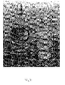
Figure 4 illustrates a space-time representation, where space is along a transmural cut, of the echographic images sequence. The transmural cut is taken as for the starting point infigure 3 . The time evolution of the starting point, tracked automatically, is reported. -
Figure 5 illustrates an echographic image of the left ventricle, in long axis view, during diastole (left) and systole (right). The original endocardial border just rescaled on the based of the mitral plane displacement is shown. The instantaneous transmural cuts on each of the originally points are also drawn. -
Figure 6 illustrates a schematic view of an example of cutting a three-dimensional dataset with two orthogonal planes, having one common direction, to get two two-dimensional images -
Figure 7 illustrates a schematic view of an example of cutting a three-dimensional dataset with transversal planes that are orthogonal to the principal planes like those employed infigure 6 . -
Figure 8 illustrates slices on a three-dimensional echographic dataset of the left heart. The left ventricle border is known on the vertical image. The border at the intersection with the horizontal slices represent the starting points for tracking the border on the horizontal images. -
Figure 9 illustrates an horizontal slice on a three-dimensional echographic dataset of the left heart. The starting points and a circular first guess border are indicated. - The method steps according to the present invention are firstly describe with reference to a two dimensional case. A sequence of two dimensional B-mode image frames is acquired. The frames are acquired at predetermined time interval one form the other.
- Consider a sequence of two-dimensional (2D) images; mathematically, this is a three-dimensional (3D) information that is 2D in space and 1D in time. Consider that the images contain one organ/object or part of it, that changes its position and shape in time, of which organ we want to trace the border kinematics at all instants.
- The method according to the present invention comprises a first step which consist in tracing the border over one single frame by defining a border line.
- A border is traced, manually or by another manual or automatic procedure, over one arbitrary frame. Such border is then defined as a sequence of N points, defined by their coordinate pairs (xi,yi) with i=1...N in the two dimensional image plane.
The result of this step is illustrated infigure 1 and2 .Figure 1 illustrates an image of the left ventricle where the endocardial border points are traced from one side of the mitral annulus to the other side of the same mitral annulus.Figure 2 illustrates an example in which the border is a closed one where the Nth point connects to the first one. - Referring now to a particular case like the one illustrated in
figure 1 , where the border has a staring and an ending point, the method according to the invention provides for a second step of tracking the most representative reference point of the border line drawn in the first image frame. - According to this step, the general topology of the object border is reproduced on all the images by tracking the motion of a few representative points. These are commonly the starting and final points of the border when this is an open one. In specific cases additional reference points can be added to improve the first evaluation of the region about which the border must be sought.
- The displacement of the representative reference points along one or more specific directions is evaluated.
Figure 3 shows the reference points for a left ventricle (in long axis view) that are the starting and final points of the originally traced border. In this case, the physiology suggests to track the motion of these points in the direction instantaneously orthogonal to the mitral plane (that is defined by these points). - The tracking along a specified direction is performed by using the method of transmural cuts as follow. A line crossing the wall, passing through the point, and directed along the physiologically appropriate direction is drawn; in the case shown in
figure 3 the appropriate direction is orthogonal to the mitral plane. In general two orthogonal direction can be employed. The pixels taken along the chosen direction line(s) are placed in columns, each column corresponding to one frame of the sequence of images. In this way the evolution along a line can be represented for all instants at once in a two dimensional space-time representation (sometime referred as M-mode representation) where one axis is the distance along the line and the other axis is the time. An example of such a representation is shown infigure 4 . - In the case of poor images with a low signal to noise ratio the space time representation can be built using a line for the transmural cut with a thickness larger than that of a single pixel and extracting the average value across such a thickness.
The border tracking is then performed along the space-time image. - The tracking procedure is a procedure for following a border along one direction in a two-dimensional image like that in
figure 4 starting from a known position at one instant. - Let us call x the horizontal direction and y the vertical direction, and indicate with xi , i=1...N, where N is the number of columns in the image. The tracking is given by determination of a discrete sequence of real numbers yi=y(xi), starting from a known point yk corresponding to the columns xk.
- This is a one dimensional tracking problem that can be solved with several possible standard methods. One method is reported here for giving completeness to the whole invention that can, however, employ also different techniques for this specific task when suggested by the specific imaging employed.
- The displacement from the known point yk to the point yk+1 can be estimated by evaluating the cross-correlation between the entire column at xk with the entire column at
xk+ 1. The cross-correlation function will present a maximum, the position of the maximum gives the value of the vertical displacement required to maximize the similarity between the two columns, therefore yk+1 is estimated by adding such a displacement to yk. This procedure is repeated between all pairs of nearby columns and the result is an estimate of the entire border yi , i=1...N. - In this procedure it is convenient to employ windowing techniques that avoid side effects given by the two ends of the finite size columns. When applicable, it is also convenient to make use of the periodicity of the signal along x in order to perform the method in Fourier space.
- The first estimate is improved by applying the same procedure recursively on increasingly reduced spatial width about the previously found border.
This first estimate yi can be further improved. To this aim a subset of the image is extracted by taking a few points above and below the first estimate yi, and a new image whose center corresponds to the sequence yi is generated. A snake procedure like the one described in Blake A., Yuille A. Active Vision MIT press, 1992., is employed to follow, in the new image, the image brightness level that passes through the fixed point yk. As a result the estimation of yi, i=1...N is refined. - As it will become clear in the following description the tracking technique is a unique procedure that is common to different steps of the method according to the present invention.
- As applied to the above mentioned step of the method according to the present invention, the result of this preliminary tracking procedure is the position and displacement, at all instants, of the most representative reference points along the predefined direction, or the vector combination when two directions are employed.
- After this, all the other points of the original border are rescaled at each instant in order to get, at each instant a topologically equivalent border geometry. Typically, like in the example of
figure 2 , all the points are translated along the original curve. - This preliminary rescaling procedure permits to keep the reference points always at the proper position in all the frames, and to rearrange the other points so that the reference maintains the same meaning in all the frames.
- The present step of tracking the most representative reference points such as the starting and ending point of a border line can be avoided when the specific geometry does not require or have any representative reference point to be tracked a priori. One example where this step can be avoided is given by the closed geometry in
figure 2 . - After having carried out the tracking of the most representative reference points if these points are present or in place of the said tracking step the method according to the invention provides for a further step consisting in the tracking of all the other reference point on the border line drawn manually or automatically in the first step on a first two dimensional image frame of the sequence of image frames.
- For each point, independently, the tracking along a specified direction is performed by using the method of transmural cuts as follow. A line crossing the wall, passing through the point, and directed along the physiologically appropriate direction is drawn, this operation is made for each instant/frame of the sequence of image frames because the points are not fixed in time but they have been previously rescaled at each instant accordingly with the instantaneous displacement of the reference points. In most cases, like in the case shown in
figure 5 , the appropriate direction is taken at each instant as orthogonal to the rescaled border. The pixels taken along each transmural line are placed in columns, each column corresponding to one frame of the sequence of images. In this way the evolution along a transmural cut, that is not fixed in all frames time but is slightly modified accordingly to the rescaling, can be represented for all instants at once in a two-dimensional space time representation analogous to that shown infigure 4 . - In the case of poor images with a low signal-to-noise ratio the space time representation can be built using a line for the transmural cut with a thickness larger than that of a single pixel and extracting the average value across such a thickness.
- The border tracking is then performed along the space-time image using the same technique employed in the step of tracking the representative reference points and disclosed above in a detailed manner.
- The result of this step is the position, at all instants, of all the points along the predefined direction, or the vector combination when two directions are employed. At this stage all the original points have been tracked in time, each one independently, and we have a new border tracked over all frames.
- It can be useful, especially in poor quality images, to improve the estimate by including a spatial coherence in the tracked border. This can be done by verifying the likelihood of the tracking between neighboring points and correcting the eventual discrepancies with appropriate filters or validation methods.
- As an additional procedure the method according to the present invention can be provided in combination with a procedure for determining the instant border line velocity vector for each one of the reference pints defined on the border line as tracked on each two dimensional frame.
- For each point, independently, the velocity vector can be known when two direction (three for three-dimensional imagin) are employed for displacing it. When a single direction is employed, the complete velocity vector can be evaluated by selecting additional direction for the transmural cuts on the already displaced point and evaluating the velocity along the additional direction.
- In the case of poor images with a low signal-to-noise ratio the space time representation can be built using a line for the transmural cut with a thickness larger than that of a single pixel and extracting the average value across such a thickness.
- Alternatively, the complete velocity vector can be evaluated by a two-dimensional correlation technique or a specific optical flow technique adapted to the particular case of ultrasound imaging B-mode data. The two-dimensional result can then be improved by imposing its accordance with the previous estimate obtained for one component from the transmural cut approach. Results of the entire procedure are shown, for one frame, in
figure 1 and2 . - The same steps described for the analysis of two-dimensional imaging can be employed for the border tracking in three-dimensional imaging. Such an extension is straightforward by using the previous steps in an appropriate combination, and substituting, in one case, the time direction with one spatial direction. Eventually no additional manual intervention is necessary with respect to what is done in two-dimensions, i.e. the indication of the border in one 2D frame.
- A sequence of three-dimensional (3D) datasets is mathematically a four-dimensional (4D) information that is 3D in space and 1D in time. Consider that the images contain one organ/object or part of it, that changes its position and shape in time, of which organ it is desired to trace the border at all instants, the border now being a sequence of two-dimensional surfaces.
- As a first step the method according to the present invention provides to choose one principal section plane which cuts to the three-dimensional dataset, and to apply the entire two-dimensional technique disclosed above on such plane.
- The principal section plane of the 3D dataset is one plane, preferably along a physiologically relevant direction. Cutting the 3D datasets of the sequence of 3D datasets with this plane furnishes one sequence of 2D images.
-
Figure 6 illustrates the cutting of a three-dimensional data set of ultrasound image data of the object 0 with two orthogonal principal section planes 1 and 2 oriented in the vertical direction. - For each principal section plane the entire tracking procedure as disclosed above for the sequence of two dimensional images is applied to this two-dimensional sequence of images taken on the principal section planes in order to track the border and evaluate the velocity on such principal section plane. This border is the signature of the sought border kinematics on the plane.
- The above steps can be repeated with more than one or two principal section planes to improve the reliability of following steps in poor quality images.
- After having carried out the above mentioned step a further step is carried out consisting in defining secondary section planes to the three-dimensional dataset, and applying the two-dimensional technique on single frames substituting the time direction with one spatial direction.
- The previous step allows to define the bounds of the surface border. For this, one direction is chosen over the plane cut used in the previous step, preferably a physiologically relevant one (like the ventricle axis), and, for each instant, evaluate the upper and lower bounds along such direction of the border found in the previous step.
- The range between these limits, at each instant, is further divided in M internal points, and the 3D dataset is cut in correspondence of such M points, with M secondary section planes that are orthogonal to the chosen direction as indicated with 3, 4, 5 in
figure 7 . By means of the said secondary section planes the corresponding M sequences of 2D images are constructed. - Successively, for each sequence, a reliable border in one single frame is defined, commonly the same frame used when the borders are drawn manually during the previous step relative to the principal section planes.
- In each of such single M frames, the border now contains one or more reliable points, at the intersection with the principal section plane or
planes 1, 2 and that come from the border(s) determined in the previous step relative to the principal section planes as illustrated infig. 8 and indicated by R1, R2, R3, R4. A first guess border is constructed as a physiological relevant one passing through these reliable points R1, R2, R3, R4. An example of the said guess border on a secondary section plane is illustrated in the example offigure 9 . Here the two dimensional image on a secondary section plane is illustrated together with the two reliable points R1 and R2. The guess border passing through the said two reliable points R1 and R2 is given by given by a circle in the transversal images of the left ventricle. - A new border is now detected by the same procedure used for a single transmural cut as disclosed in the previous chapter for the two dimensional case, this time however, substituting the time coordinate with the spatial coordinate along such first guess border as follows. Make a number of transmural cuts on the single image along the guess border, place the pixel found along each cut side by side in a new two-dimensional image and obtain a new image, like that in
figure 4 , where the horizontal axis does not indicate the time coordinate but the spatial coordinate along the tentative border. As a result the correct border is tracked in one frame for each of the M sequences. - The above mentioned procedure is applied on all the sequences obtained from the appropriate cutting of the three-dimensional dataset according to each secondary section plane defined. The tracking technique disclosed above in the previous chapter of the two dimensional ultrasound imaging is applied to each of the M sequences taking as a starting, reliable, border that found on one frame in the step relating to the secondary section planes. The resulting M borders will define the complete surface border.
- Similarly to the two dimensional case discussed above also in the three-dimensional imaging case the instantaneous velocity vector for a certain number of predefined points on the border surface can be calculated by using the same technique disclosed of the two dimensional case. The two dimensional technique disclosed above is used here by substituting the two dimensional estimate with a three-dimensional estimate of velocity.
- When the tracking procedure is insufficient to define the entire velocity vector, this is done by selecting additional direction for the transmural cuts on the already displaced point and evaluating the velocity along the additional direction.
- Alternatively, this is done by using a three-dimensional correlation or optical flow technique, in place of the two-dimensional one for evaluating the three-dimensional velocity vector.
Claims (13)
- A method of tracking position and velocity of objects' borders in two or three dimensional echographic images comprising the following steps:Acquiring a sequence of at least two consecutive ultrasound image frames of a moving tissue or a moving object which ultrasound image frames are timely separated by a certain time interval.Automatically or manually defining a certain number of reference points of a border of a moving tissue or object at least on a first image frame of the sequence of image frames acquired;Automatically tracking the border of the moving tissue or object in the at least one further following frame by determining the new position of the reference points of the border in at least one following image frame of the sequence of image frames by estimating the position of the said reference points in the said at least following image frame of the sequence of image frames on the basis of the ultrasound image data of the acquired sequence of image frames.the sequence of image frames acquired is a sequence of consecutive B-mode, grey scale ultrasound images;On a first frame a border line is drawn either manually or by means of an automatic border detection algorithm the border being defined by a trace of pixels of the image frame coinciding with the said border line;The original trace of pixels coinciding with the manually or automatically drawn border line is followed in time, i.e. in the at least one following image frame by searching the maximum likelihood of the trace of pixels in the following image frame with the trace of pixels in the first or timely previous image frame of the sequence of image frames by analyzing the image pixels in the neighbourhood of the said trace of pixels;the tracking of the border line is carried out by defining a certain number of reference points on the manually or automatically drawn border line on the first image frame and by using the method of the so called transmural cuts.the said transmural cuts consist in defining for each reference point a line which crosses the border line drawn on a first image frame and each of which lines passing through one reference point; each transmural cut line having a definite direction, which typically can be the orthogonal direction to the border line at the reference point;carrying out the above mentioned step of defining transmural cuts for each image frame of the sequence of frames and for each reference point chosen;the pixels taken along each transmural line in each of the image frames of the sequence of image frames being than placed in columns, each column corresponding to one frame of the sequence of images, forming a two-dimensional space-time representation of the evolution of the position of each reference point along the corresponding transmural cut;the tracking of the border line i.e. of the trace of pixels, is carried out for each reference point defined on the said border line along the corresponding two-dimensional space-time image using a cross-correlation procedure of the pixel column in the space-time image corresponding to a first image frame with the pixel column in the space-time image corresponding to a successive image frame of the sequence of image frames,
the method
comprising steps for determining the border line instant velocity on each image frame of the sequence of image frames, whereby a first estimation of the
instant velocity is determined for each reference point on the border line by dividing the displacement vector of each of the reference point from a first to a following image frames of the sequence of image frames by the time interval occurred between the said first and said following image frames,And which method is further characterized by the steps ofDetermining the components of the velocity vector on each of the image frames of the sequence of image frames for each of the reference points on the border-line by selecting additional direction for the transmural cuts on the already displaced point and evaluating the velocity along the additional direction by applying the said method steps of the so called transmural cuts along the said additional direction required to evaluate the complete velocity vector;The evaluation of each of the component(s) of the velocity vector along each direction, the total number of components being two for two-dimensional imaging and being three for three-dimensional imaging ;
being carried out according to the following steps:aa) For each reference point, on each image frame of the sequence of image frames, a transmural cut consisting in a line which crosses the tracked point and directed along the direction where the additional component of velocity is evaluated, orthogonal to the direction for the other components of the velocity vector.bb) the pixels taken along each transmural cut line in each of the image frames of the sequence of image frames are placed in columns for all instants at once in a two-dimensional space time representation;cc) the evaluation of the velocity component along the chosen direction is carried out along the space-time image using a cross-correlation procedure of the pixel column in the space-time image, the said velocity being given by the ratio of the column-wise displacement of the correlation maximum and the time interval between the corresponding frames. - A method according to claim 1, characterised in that it is applied to closed border lines.
- A method according to one or more of the preceding claims in combination with objects imaged having at least one or more representative reference points in particular a starting and an ending point of a border which having a relevance as particular reference points in the motion executed by the border-line of the object,
characterised in that prior of carrying out the tracking of all the reference points defined on the border line drawn on a first image frame of the sequence of at least two image frames a preventive tracking cycle of only the representative reference points is carried out according to the method of one or more of claims 1 to 2. - A method according to claim 3, characterised in that the tracking of the representative reference points is carried out by using the method of transmural cuts for constructing space-time images of each of the representative reference points and determining the displacement of these points in each of the frames of the sequence of image frames by means of cross-correlation between each of the pixel columns with the successive pixel column corresponding to the pixels along the transmural cut across the same representative reference point in the different image frames of the sequence of image frames.
- A method according to claim 3 or 4, characterised in that after having determined the displacement of the representative reference points on the border-line of the imaged object in some or in all of the frames of the sequence of image frames, the position and the displacement of the other reference points on the border-lines at each image frame of the sequence of image frames are obtained by rescaling the originally, manually or automatically drawn border-line in the first image frame in such a way to obtain in each image frame corresponding to a successive instant a topologically equivalent border line geometry with respect to the original border line and to keep the representative reference points always in the proper position in all frames of the sequence of image frames by rearranging the other reference points so that the representative reference points maintains the same meaning relatively to the object in all frames of the sequence of image frames.
- A method according to one or more of the preceding claims characterised by the following steps:a) Acquiring a sequence of at least two consecutive ultrasound image frames of a moving tissue or a moving object which ultrasound image frames are timely separated by a certain time interval;b) Tracing a border line over one single first frame either manually or with the help of an automatic border drawing algorithm;c) Tracking the position displacements of one or more eventually present representative reference points over the entire sequence of consecutive image frames;d) Rescaling the border line drawn on the first image frame at least for some or for each of the following image frames of the sequence of image frames according to the corresponding position tracked of the representative reference points;e) Defining a certain number of further reference points distributed along the border line on the first image frame and falling on the said border line;f) Tracking the position of each point independently from the others along the sequence of image frames;g) Tracking of the position of the representative reference points and of the other reference points being carried out byh) for each point independently and in each of the image frames of the sequence of image frames defining a transmural cut line consisting in a line which crosses the border line drawn and passing through the said reference point;i) the pixels taken along each transmural cut line in each of the image frames of the sequence of image frames are placed in columns, each column corresponding to one frame of the sequence of images for representing the evolution along a transmural cut line, for all instants at once in a two-dimensional space time representation;j) the tracking of the border. i.e. of the trace of pixels along each transmural cut line is carried out along the space-time image using a cross-correlation procedure of the pixel column in the space-time image corresponding to a first image frame with the pixel column in the space-time image corresponding to a successive image frame of the sequence of image frames.
- A method according to one or more of the preceding claims characterised in that in combination of images of poor quality, i.e. with a low signal-to noise-ratio, the space-time representation along the transmural cuts is built using a line for the transmural cut with a thickness larger than that of a single pixel and by extracting the average value across such a thickness.
- A method according to one or more of the preceding claims characterised in that it is applied for carrying out a surface border tracking in three-dimensional imaging and comprising the following steps:l) Acquiring a sequence of three-dimensional ultrasound imaging data sets, each three-dimensional data set being acquired with a predetermined time interval from the previous one;m) Defining at least a principal section plane of each three dimensional data set along one chosen direction for obtaining a sequence of two dimensional image frames along the said section plane;n) Drawing a border line of the object imaged either manually or automatically on the first two dimensional image frame of the sequence of two dimensional image frames taken along the said principal section plane or each of the said principal section planes;o) Carrying out the tracking steps c) to j) previously disclosed for the each sequence of two-dimensional image frames for each corresponding principal section plane;p) For each three-dimensional data set of the sequence of three-dimensional datasets defining a preestablished number of further secondary section planes crossing the at least one, preferably all the principal section planes, the said secondary section planes being spaced apart one from the other along a predetermined direction and dividing the object represented by each three-dimensional data set of the sequence of three-dimensional data sets in slices.q) For each secondary section plane in the sequence of three dimensional data sets constructing the corresponding sequence of two-dimensional image frames relative to the said secondary section plane;r) For each sequence of two-dimensional image frames relatively to each secondary section plane determining a guess border line in one single frame, by letting the guess border line passing across the intersection points of the corresponding secondary section plane with the border line drawn on the principal section plane or of the principal section planes;s) Tracking the said guess border line by detecting a new border by applying the method steps according to c) to j) or e) to j) by substituting the time coordinate in the said disclosed steps with the spatial coordinate along the said guess border line byt) defining a certain number of transmural cuts on the single image frame of the sequence of images frames corresponding to each secondary section plane along the guess border line;u) identifying the pixels along the said transmural cuts and placing the pixels along each tansmural cuts side by side for constructing a two-dimensional image where the horizontal axis indicates the spatial coordinate along the guess border line;v) carrying out the cross correlation between each of the consecutive pixel columns in the said two dimensional image and thus tracking the border line in one frame for each of the sequences of two-dimensional image frames corresponding to each of the secondary section planes.
- A method according to claim 8, characterised in that one or more further principal section planes can be defined along each of which further section planes the methods steps 1) to o) are carried out.
- A method according to claims 8 or 9, characterised in that two orthogonal principal section planes are chosen for carrying out the above mentioned method steps, the crossing line of the two principal section planes defining a preferred direction of the said planes.
- A method according to one or more of the preceding claims 8 to 10, characterised in that in order to better define the group of secondary section planes cutting the principal section planes, the following steps are provided: defining bounds or limits for a distance range within which the group of the said secondary section planes has to be defined.
- A method according to claim 11, characterised in that a direction along which the secondary section planes are distributed is chosen, which is the same direction defined for determining the principal section planes, along which direction bounds are determined for the ends of a distance range within which the group of secondary section planes are defined and which secondary section planes are at least transversal, particularly perpendicular to the said direction.
- A method according to one or more of the preceding claims the correct border line tracked is displayed overlaid on the corresponding displayed image frame as an highlighted line characterized by a colour which is different from the grey-scale B-mode image displayed.
Priority Applications (4)
| Application Number | Priority Date | Filing Date | Title |
|---|---|---|---|
| AT03425639T ATE550680T1 (en) | 2003-09-30 | 2003-09-30 | METHOD FOR POSITION AND VELOCITY TRACKING OF AN OBJECT EDGE IN TWO OR THREE DIMENSIONAL DIGITAL ECHOGRAPHIC IMAGES |
| EP03425639A EP1522875B1 (en) | 2003-09-30 | 2003-09-30 | A method of tracking position and velocity of object's borders in two or three dimensional digital echographic images |
| US10/956,797 US7343031B2 (en) | 2003-09-30 | 2004-09-30 | Method of tracking position and velocity of objects' borders in two or three dimensional digital images, particularly in echographic images |
| US12/015,264 US8098912B2 (en) | 2003-09-30 | 2008-01-16 | Method of tracking position and velocity of objects' borders in two or three dimensional digital images, particularly in echographic images |
Applications Claiming Priority (1)
| Application Number | Priority Date | Filing Date | Title |
|---|---|---|---|
| EP03425639A EP1522875B1 (en) | 2003-09-30 | 2003-09-30 | A method of tracking position and velocity of object's borders in two or three dimensional digital echographic images |
Publications (2)
| Publication Number | Publication Date |
|---|---|
| EP1522875A1 EP1522875A1 (en) | 2005-04-13 |
| EP1522875B1 true EP1522875B1 (en) | 2012-03-21 |
Family
ID=34307071
Family Applications (1)
| Application Number | Title | Priority Date | Filing Date |
|---|---|---|---|
| EP03425639A Expired - Lifetime EP1522875B1 (en) | 2003-09-30 | 2003-09-30 | A method of tracking position and velocity of object's borders in two or three dimensional digital echographic images |
Country Status (3)
| Country | Link |
|---|---|
| US (2) | US7343031B2 (en) |
| EP (1) | EP1522875B1 (en) |
| AT (1) | ATE550680T1 (en) |
Families Citing this family (46)
| Publication number | Priority date | Publication date | Assignee | Title |
|---|---|---|---|---|
| US7766837B2 (en) * | 2002-02-27 | 2010-08-03 | Esaote S.P.A. | M-tracking for space-time image |
| US7714855B2 (en) * | 2004-05-17 | 2010-05-11 | Siemens Medical Solutions Usa, Inc. | Volume rendering processing distribution in a graphics processing unit |
| CN101141920B (en) * | 2005-03-15 | 2011-12-14 | 株式会社东芝 | Ultrasonic diagnostic equipment and its controlling program |
| US20060239527A1 (en) * | 2005-04-25 | 2006-10-26 | Sriram Krishnan | Three-dimensional cardiac border delineation in medical imaging |
| EP1876954A4 (en) * | 2005-05-02 | 2009-12-16 | Agency Science Tech & Res | METHOD AND DEVICE FOR REGISTERING AN ATLAS TO A PICTURE |
| US7852335B2 (en) * | 2005-05-09 | 2010-12-14 | Siemens Medical Solutions Usa, Inc. | Volume rendering processing distribution in a graphics processing unit |
| EP1731102A1 (en) | 2005-06-08 | 2006-12-13 | Esaote S.p.A. | Method for measuring and displaying time varying events |
| CA2618101A1 (en) * | 2005-08-19 | 2007-02-22 | Visualsonics Inc. | Systems and methods for capture and display of blood pressure and ultrasound data |
| US20070071295A1 (en) * | 2005-09-27 | 2007-03-29 | Siemens Medical Solutions Usa, Inc. | Orientation-based assessment of cardiac synchrony in medical imaging |
| CN101273382A (en) * | 2005-09-28 | 2008-09-24 | 皇家飞利浦电子股份有限公司 | Method for reference contour propagation and optimization |
| EP1772825A1 (en) * | 2005-10-06 | 2007-04-11 | Esaote S.p.A. | Method for registering images of a sequence of images, particularly ultrasound diagnostic images |
| US7831074B2 (en) * | 2005-10-12 | 2010-11-09 | Siemens Corporation | System and method for using a similarity function to perform appearance matching in image pairs |
| JP2009512486A (en) * | 2005-10-20 | 2009-03-26 | コーニンクレッカ フィリップス エレクトロニクス エヌ ヴィ | Ultrasound imaging system and method |
| JP4984509B2 (en) * | 2005-12-06 | 2012-07-25 | ソニー株式会社 | Positioning information processing apparatus, positioning information processing method, program |
| US20070196005A1 (en) * | 2006-02-23 | 2007-08-23 | White Christopher A | Feature Tracing Process for M-mode Images |
| US7803113B2 (en) * | 2006-06-14 | 2010-09-28 | Siemens Medical Solutions Usa, Inc. | Ultrasound imaging of rotation |
| EP1876567A1 (en) * | 2006-07-04 | 2008-01-09 | Esaote S.p.A. | A method of determining the time dependent behavior of non rigid moving objects, particularly of biological tissues, from echographic ultrasound imaging data |
| EP1892671A3 (en) * | 2006-08-23 | 2009-07-29 | Medison Co., Ltd. | System and method for determining the volume of an object by image processing |
| JP4751282B2 (en) * | 2006-09-27 | 2011-08-17 | 株式会社日立製作所 | Ultrasonic diagnostic equipment |
| US20080095417A1 (en) * | 2006-10-23 | 2008-04-24 | Gianni Pedrizzetti | Method for registering images of a sequence of images, particularly ultrasound diagnostic images |
| US8540635B2 (en) * | 2007-07-12 | 2013-09-24 | Siemens Medical Solutions Usa, Inc. | Medical diagnostic imaging with hardware generated region of interest border |
| EP2026280B1 (en) | 2007-07-23 | 2013-10-23 | Esaote S.p.A. | Method and corresponding apparatus for quantitative measurements on sequences of images, particularly ultrasonic images |
| KR20090095150A (en) * | 2008-03-05 | 2009-09-09 | 주식회사 메디슨 | Ultrasound system and methdo for processing ultrasound image |
| JP5075757B2 (en) * | 2008-08-05 | 2012-11-21 | オリンパス株式会社 | Image processing apparatus, image processing program, image processing method, and electronic apparatus |
| JP5523791B2 (en) * | 2008-10-27 | 2014-06-18 | 株式会社東芝 | X-ray diagnostic apparatus and image processing apparatus |
| US8199994B2 (en) * | 2009-03-13 | 2012-06-12 | International Business Machines Corporation | Automatic analysis of cardiac M-mode views |
| CN101926676B (en) * | 2009-06-25 | 2012-07-25 | 谢耀钦 | Medical images-tracking method capable of automatically identifying characteristic points and device thereof |
| KR101182999B1 (en) * | 2009-11-25 | 2012-09-18 | 삼성메디슨 주식회사 | Ultrasound system and method for performing ultrasound image processing |
| CN102081697B (en) * | 2009-11-27 | 2013-12-11 | 深圳迈瑞生物医疗电子股份有限公司 | Method and device for defining interested volume in ultrasonic imaging space |
| WO2011093193A1 (en) * | 2010-01-29 | 2011-08-04 | 株式会社 日立メディコ | Ultrasonic diagnosis device and method used therefor to track measurement point |
| WO2012090208A2 (en) | 2010-12-29 | 2012-07-05 | Diacardio Ltd. | Automatic left ventricular function evaluation |
| CN103473543B (en) * | 2012-06-07 | 2016-10-05 | 富士通株式会社 | For extracting device, method and the electronic equipment on objects in images border |
| KR101382625B1 (en) * | 2012-10-17 | 2014-04-10 | 고려대학교 산학협력단 | Apparatus and method for computing dynamic variation of target object |
| GB2507987A (en) * | 2012-11-15 | 2014-05-21 | Imp Innovations Ltd | Method of automatically processing an ultrasound image |
| ITAQ20130003A1 (en) | 2013-04-23 | 2014-10-24 | Amid S R L | METHOD AND DEVICE FOR THE ASSESSMENT OF THE QUANTITATIVE DYNAMIC FUNCTIONALITY OF THE SKELETAL MUSCLES |
| US9360850B2 (en) * | 2013-11-25 | 2016-06-07 | Rutgers, The State University Of New Jersey | Modular monitor and control system for cell sorter stream |
| WO2015124388A1 (en) * | 2014-02-19 | 2015-08-27 | Koninklijke Philips N.V. | Motion adaptive visualization in medical 4d imaging |
| US9684830B2 (en) * | 2014-11-14 | 2017-06-20 | Intel Corporation | Automatic target selection for multi-target object tracking |
| CN105748100B (en) * | 2014-12-19 | 2019-04-16 | 深圳开立生物医疗科技股份有限公司 | Quasi-static ultrasonic elastograph imaging displacement calculates method and apparatus |
| GB201610269D0 (en) | 2016-06-13 | 2016-07-27 | Isis Innovation | Image-based diagnostic systems |
| DE102016117889B3 (en) * | 2016-09-22 | 2018-03-15 | Tomtec Imaging Systems Gmbh | Method and device for correcting dynamic models determined by tracking methods |
| CN108309354B (en) * | 2017-01-16 | 2021-04-02 | 深圳迈瑞生物医疗电子股份有限公司 | Ultrasonic pelvic floor detection and guidance method and ultrasonic imaging system |
| CN109745069A (en) * | 2017-11-01 | 2019-05-14 | 通用电气公司 | ultrasonic imaging method |
| GB2569332B (en) | 2017-12-13 | 2021-06-09 | Univ Oxford Innovation Ltd | Method and apparatus for analysing images |
| GB2569333A (en) | 2017-12-13 | 2019-06-19 | Univ Oxford Innovation Ltd | Diagnostic modelling method and apparatus |
| JP7099901B2 (en) * | 2018-08-06 | 2022-07-12 | 富士フイルムヘルスケア株式会社 | Ultrasound image processing equipment and programs |
Family Cites Families (8)
| Publication number | Priority date | Publication date | Assignee | Title |
|---|---|---|---|---|
| US5622174A (en) * | 1992-10-02 | 1997-04-22 | Kabushiki Kaisha Toshiba | Ultrasonic diagnosis apparatus and image displaying system |
| NO943214D0 (en) * | 1994-08-30 | 1994-08-30 | Vingmed Sound As | Method of ultrasound imaging |
| JP3514553B2 (en) * | 1995-06-30 | 2004-03-31 | フクダ電子株式会社 | Ultrasound diagnostic equipment |
| EP1090372A2 (en) * | 1998-03-30 | 2001-04-11 | Echovision, Inc. | Echocardiography workstation |
| EP1122521A1 (en) * | 2000-02-01 | 2001-08-08 | Setrix AG | Method and apparatus for monitoring an analog meter |
| US6537221B2 (en) * | 2000-12-07 | 2003-03-25 | Koninklijke Philips Electronics, N.V. | Strain rate analysis in ultrasonic diagnostic images |
| US6638221B2 (en) * | 2001-09-21 | 2003-10-28 | Kabushiki Kaisha Toshiba | Ultrasound diagnostic apparatus, and image processing method |
| US7766837B2 (en) * | 2002-02-27 | 2010-08-03 | Esaote S.P.A. | M-tracking for space-time image |
-
2003
- 2003-09-30 AT AT03425639T patent/ATE550680T1/en active
- 2003-09-30 EP EP03425639A patent/EP1522875B1/en not_active Expired - Lifetime
-
2004
- 2004-09-30 US US10/956,797 patent/US7343031B2/en not_active Expired - Lifetime
-
2008
- 2008-01-16 US US12/015,264 patent/US8098912B2/en not_active Expired - Fee Related
Also Published As
| Publication number | Publication date |
|---|---|
| ATE550680T1 (en) | 2012-04-15 |
| US20050074153A1 (en) | 2005-04-07 |
| US20080118109A1 (en) | 2008-05-22 |
| US8098912B2 (en) | 2012-01-17 |
| EP1522875A1 (en) | 2005-04-13 |
| US7343031B2 (en) | 2008-03-11 |
Similar Documents
| Publication | Publication Date | Title |
|---|---|---|
| EP1522875B1 (en) | A method of tracking position and velocity of object's borders in two or three dimensional digital echographic images | |
| US11510651B2 (en) | Ultrasonic diagnosis of cardiac performance using heart model chamber segmentation with user control | |
| EP0880937B1 (en) | Ultrasonic diagnostic imaging system with doppler assisted tracking of tissue motion | |
| US6994673B2 (en) | Method and apparatus for quantitative myocardial assessment | |
| US6503202B1 (en) | Medical diagnostic ultrasound system and method for flow analysis | |
| US8538103B2 (en) | Medical image processing device, medical image processing method, medical image diagnostic apparatus, operation method of medical image diagnostic apparatus, and medical image display method | |
| EP1579244B1 (en) | Segmentation tool for identifying flow regions in an imaging system | |
| JP4699724B2 (en) | Method and apparatus for obtaining a volumetric scan on a periodically moving object | |
| US6980844B2 (en) | Method and apparatus for correcting a volumetric scan of an object moving at an uneven period | |
| US20070276245A1 (en) | System And Method For Automated Boundary Detection Of Body Structures | |
| US10398411B2 (en) | Automatic alignment of ultrasound volumes | |
| US20020072672A1 (en) | Analysis of cardiac performance using ultrasonic diagnostic images | |
| US20080095417A1 (en) | Method for registering images of a sequence of images, particularly ultrasound diagnostic images | |
| US20060004291A1 (en) | Methods and apparatus for visualization of quantitative data on a model | |
| US7907758B2 (en) | Method and system for maintaining consistent anatomic views in displayed image data | |
| CN111885965A (en) | Ultrasound system for shear wave imaging in three dimensions | |
| EP3267896B1 (en) | Ultrasonic diagnosis of cardiac performance by single degree of freedom chamber segmentation | |
| CN112826535B (en) | Method, device and equipment for automatically positioning blood vessel in ultrasonic imaging | |
| EP1772825A1 (en) | Method for registering images of a sequence of images, particularly ultrasound diagnostic images | |
| EP1876567A1 (en) | A method of determining the time dependent behavior of non rigid moving objects, particularly of biological tissues, from echographic ultrasound imaging data |
Legal Events
| Date | Code | Title | Description |
|---|---|---|---|
| PUAI | Public reference made under article 153(3) epc to a published international application that has entered the european phase |
Free format text: ORIGINAL CODE: 0009012 |
|
| 17P | Request for examination filed |
Effective date: 20040618 |
|
| AK | Designated contracting states |
Kind code of ref document: A1 Designated state(s): AT BE BG CH CY CZ DE DK EE ES FI FR GB GR HU IE IT LI LU MC NL PT RO SE SI SK TR |
|
| AX | Request for extension of the european patent |
Extension state: AL LT LV MK |
|
| RAP1 | Party data changed (applicant data changed or rights of an application transferred) |
Owner name: ESAOTE S.P.A. Owner name: AMID S.R.L. |
|
| AKX | Designation fees paid |
Designated state(s): AT BE BG CH CY CZ DE DK EE ES FI FR GB GR HU IE IT LI LU MC NL PT RO SE SI SK TR |
|
| RAP1 | Party data changed (applicant data changed or rights of an application transferred) |
Owner name: AMID S.R.L. Owner name: ESAOTE S.P.A. |
|
| RAP1 | Party data changed (applicant data changed or rights of an application transferred) |
Owner name: AMID S.R.L. Owner name: ESAOTE S.P.A. |
|
| 17Q | First examination report despatched |
Effective date: 20070420 |
|
| RAP1 | Party data changed (applicant data changed or rights of an application transferred) |
Owner name: AMID S.R.L. Owner name: ESAOTE S.P.A. Owner name: BRACCO IMAGING S.P.A |
|
| GRAP | Despatch of communication of intention to grant a patent |
Free format text: ORIGINAL CODE: EPIDOSNIGR1 |
|
| RTI1 | Title (correction) |
Free format text: A METHOD OF TRACKING POSITION AND VELOCITY OF OBJECT'S BORDERS IN TWO OR THREE DIMENSIONAL DIGITAL ECHOGRAPHIC IMAGES |
|
| GRAS | Grant fee paid |
Free format text: ORIGINAL CODE: EPIDOSNIGR3 |
|
| GRAA | (expected) grant |
Free format text: ORIGINAL CODE: 0009210 |
|
| AK | Designated contracting states |
Kind code of ref document: B1 Designated state(s): AT BE BG CH CY CZ DE DK EE ES FI FR GB GR HU IE IT LI LU MC NL PT RO SE SI SK TR |
|
| RAP1 | Party data changed (applicant data changed or rights of an application transferred) |
Owner name: BRACCO IMAGING S.P.A Owner name: ESAOTE S.P.A. |
|
| REG | Reference to a national code |
Ref country code: GB Ref legal event code: FG4D |
|
| REG | Reference to a national code |
Ref country code: CH Ref legal event code: EP |
|
| REG | Reference to a national code |
Ref country code: IE Ref legal event code: FG4D |
|
| REG | Reference to a national code |
Ref country code: AT Ref legal event code: REF Ref document number: 550680 Country of ref document: AT Kind code of ref document: T Effective date: 20120415 |
|
| REG | Reference to a national code |
Ref country code: DE Ref legal event code: R096 Ref document number: 60340325 Country of ref document: DE Effective date: 20120516 |
|
| REG | Reference to a national code |
Ref country code: NL Ref legal event code: VDEP Effective date: 20120321 |
|
| PG25 | Lapsed in a contracting state [announced via postgrant information from national office to epo] |
Ref country code: FI Free format text: LAPSE BECAUSE OF FAILURE TO SUBMIT A TRANSLATION OF THE DESCRIPTION OR TO PAY THE FEE WITHIN THE PRESCRIBED TIME-LIMIT Effective date: 20120321 Ref country code: GR Free format text: LAPSE BECAUSE OF FAILURE TO SUBMIT A TRANSLATION OF THE DESCRIPTION OR TO PAY THE FEE WITHIN THE PRESCRIBED TIME-LIMIT Effective date: 20120622 |
|
| REG | Reference to a national code |
Ref country code: AT Ref legal event code: MK05 Ref document number: 550680 Country of ref document: AT Kind code of ref document: T Effective date: 20120321 |
|
| PG25 | Lapsed in a contracting state [announced via postgrant information from national office to epo] |
Ref country code: CY Free format text: LAPSE BECAUSE OF FAILURE TO SUBMIT A TRANSLATION OF THE DESCRIPTION OR TO PAY THE FEE WITHIN THE PRESCRIBED TIME-LIMIT Effective date: 20120321 |
|
| PG25 | Lapsed in a contracting state [announced via postgrant information from national office to epo] |
Ref country code: CZ Free format text: LAPSE BECAUSE OF FAILURE TO SUBMIT A TRANSLATION OF THE DESCRIPTION OR TO PAY THE FEE WITHIN THE PRESCRIBED TIME-LIMIT Effective date: 20120321 Ref country code: EE Free format text: LAPSE BECAUSE OF FAILURE TO SUBMIT A TRANSLATION OF THE DESCRIPTION OR TO PAY THE FEE WITHIN THE PRESCRIBED TIME-LIMIT Effective date: 20120321 Ref country code: BE Free format text: LAPSE BECAUSE OF FAILURE TO SUBMIT A TRANSLATION OF THE DESCRIPTION OR TO PAY THE FEE WITHIN THE PRESCRIBED TIME-LIMIT Effective date: 20120321 Ref country code: SE Free format text: LAPSE BECAUSE OF FAILURE TO SUBMIT A TRANSLATION OF THE DESCRIPTION OR TO PAY THE FEE WITHIN THE PRESCRIBED TIME-LIMIT Effective date: 20120321 Ref country code: RO Free format text: LAPSE BECAUSE OF FAILURE TO SUBMIT A TRANSLATION OF THE DESCRIPTION OR TO PAY THE FEE WITHIN THE PRESCRIBED TIME-LIMIT Effective date: 20120321 Ref country code: SI Free format text: LAPSE BECAUSE OF FAILURE TO SUBMIT A TRANSLATION OF THE DESCRIPTION OR TO PAY THE FEE WITHIN THE PRESCRIBED TIME-LIMIT Effective date: 20120321 |
|
| PG25 | Lapsed in a contracting state [announced via postgrant information from national office to epo] |
Ref country code: PT Free format text: LAPSE BECAUSE OF FAILURE TO SUBMIT A TRANSLATION OF THE DESCRIPTION OR TO PAY THE FEE WITHIN THE PRESCRIBED TIME-LIMIT Effective date: 20120723 Ref country code: SK Free format text: LAPSE BECAUSE OF FAILURE TO SUBMIT A TRANSLATION OF THE DESCRIPTION OR TO PAY THE FEE WITHIN THE PRESCRIBED TIME-LIMIT Effective date: 20120321 |
|
| PLBE | No opposition filed within time limit |
Free format text: ORIGINAL CODE: 0009261 |
|
| STAA | Information on the status of an ep patent application or granted ep patent |
Free format text: STATUS: NO OPPOSITION FILED WITHIN TIME LIMIT |
|
| PG25 | Lapsed in a contracting state [announced via postgrant information from national office to epo] |
Ref country code: NL Free format text: LAPSE BECAUSE OF FAILURE TO SUBMIT A TRANSLATION OF THE DESCRIPTION OR TO PAY THE FEE WITHIN THE PRESCRIBED TIME-LIMIT Effective date: 20120321 Ref country code: AT Free format text: LAPSE BECAUSE OF FAILURE TO SUBMIT A TRANSLATION OF THE DESCRIPTION OR TO PAY THE FEE WITHIN THE PRESCRIBED TIME-LIMIT Effective date: 20120321 Ref country code: DK Free format text: LAPSE BECAUSE OF FAILURE TO SUBMIT A TRANSLATION OF THE DESCRIPTION OR TO PAY THE FEE WITHIN THE PRESCRIBED TIME-LIMIT Effective date: 20120321 |
|
| 26N | No opposition filed |
Effective date: 20130102 |
|
| REG | Reference to a national code |
Ref country code: DE Ref legal event code: R097 Ref document number: 60340325 Country of ref document: DE Effective date: 20130102 |
|
| PG25 | Lapsed in a contracting state [announced via postgrant information from national office to epo] |
Ref country code: ES Free format text: LAPSE BECAUSE OF FAILURE TO SUBMIT A TRANSLATION OF THE DESCRIPTION OR TO PAY THE FEE WITHIN THE PRESCRIBED TIME-LIMIT Effective date: 20120702 Ref country code: MC Free format text: LAPSE BECAUSE OF NON-PAYMENT OF DUE FEES Effective date: 20120930 |
|
| REG | Reference to a national code |
Ref country code: CH Ref legal event code: PL |
|
| REG | Reference to a national code |
Ref country code: IE Ref legal event code: MM4A |
|
| PG25 | Lapsed in a contracting state [announced via postgrant information from national office to epo] |
Ref country code: CH Free format text: LAPSE BECAUSE OF NON-PAYMENT OF DUE FEES Effective date: 20120930 Ref country code: BG Free format text: LAPSE BECAUSE OF FAILURE TO SUBMIT A TRANSLATION OF THE DESCRIPTION OR TO PAY THE FEE WITHIN THE PRESCRIBED TIME-LIMIT Effective date: 20120621 Ref country code: LI Free format text: LAPSE BECAUSE OF NON-PAYMENT OF DUE FEES Effective date: 20120930 Ref country code: IE Free format text: LAPSE BECAUSE OF NON-PAYMENT OF DUE FEES Effective date: 20120930 |
|
| PG25 | Lapsed in a contracting state [announced via postgrant information from national office to epo] |
Ref country code: TR Free format text: LAPSE BECAUSE OF FAILURE TO SUBMIT A TRANSLATION OF THE DESCRIPTION OR TO PAY THE FEE WITHIN THE PRESCRIBED TIME-LIMIT Effective date: 20120321 |
|
| PG25 | Lapsed in a contracting state [announced via postgrant information from national office to epo] |
Ref country code: LU Free format text: LAPSE BECAUSE OF NON-PAYMENT OF DUE FEES Effective date: 20120930 |
|
| PG25 | Lapsed in a contracting state [announced via postgrant information from national office to epo] |
Ref country code: HU Free format text: LAPSE BECAUSE OF FAILURE TO SUBMIT A TRANSLATION OF THE DESCRIPTION OR TO PAY THE FEE WITHIN THE PRESCRIBED TIME-LIMIT Effective date: 20030930 |
|
| REG | Reference to a national code |
Ref country code: FR Ref legal event code: PLFP Year of fee payment: 14 |
|
| REG | Reference to a national code |
Ref country code: FR Ref legal event code: PLFP Year of fee payment: 15 |
|
| REG | Reference to a national code |
Ref country code: FR Ref legal event code: PLFP Year of fee payment: 16 |
|
| PGFP | Annual fee paid to national office [announced via postgrant information from national office to epo] |
Ref country code: FR Payment date: 20210913 Year of fee payment: 19 |
|
| PGFP | Annual fee paid to national office [announced via postgrant information from national office to epo] |
Ref country code: GB Payment date: 20210920 Year of fee payment: 19 Ref country code: DE Payment date: 20210914 Year of fee payment: 19 |
|
| PGFP | Annual fee paid to national office [announced via postgrant information from national office to epo] |
Ref country code: IT Payment date: 20220906 Year of fee payment: 20 |
|
| REG | Reference to a national code |
Ref country code: DE Ref legal event code: R119 Ref document number: 60340325 Country of ref document: DE |
|
| GBPC | Gb: european patent ceased through non-payment of renewal fee |
Effective date: 20220930 |
|
| PG25 | Lapsed in a contracting state [announced via postgrant information from national office to epo] |
Ref country code: FR Free format text: LAPSE BECAUSE OF NON-PAYMENT OF DUE FEES Effective date: 20220930 Ref country code: DE Free format text: LAPSE BECAUSE OF NON-PAYMENT OF DUE FEES Effective date: 20230401 |
|
| PG25 | Lapsed in a contracting state [announced via postgrant information from national office to epo] |
Ref country code: GB Free format text: LAPSE BECAUSE OF NON-PAYMENT OF DUE FEES Effective date: 20220930 |