JP2009523544A - Systems and methods for differentiating and / or identifying tissue sites stimulated by targeted nerves for diagnostic and / or therapeutic purposes - Google Patents
Systems and methods for differentiating and / or identifying tissue sites stimulated by targeted nerves for diagnostic and / or therapeutic purposes Download PDFInfo
- Publication number
- JP2009523544A JP2009523544A JP2008551363A JP2008551363A JP2009523544A JP 2009523544 A JP2009523544 A JP 2009523544A JP 2008551363 A JP2008551363 A JP 2008551363A JP 2008551363 A JP2008551363 A JP 2008551363A JP 2009523544 A JP2009523544 A JP 2009523544A
- Authority
- JP
- Japan
- Prior art keywords
- instrument
- heart
- fat pad
- site
- targeted
- Prior art date
- Legal status (The legal status is an assumption and is not a legal conclusion. Google has not performed a legal analysis and makes no representation as to the accuracy of the status listed.)
- Pending
Links
Images


Classifications
-
- A—HUMAN NECESSITIES
- A61—MEDICAL OR VETERINARY SCIENCE; HYGIENE
- A61B—DIAGNOSIS; SURGERY; IDENTIFICATION
- A61B5/00—Measuring for diagnostic purposes; Identification of persons
- A61B5/05—Detecting, measuring or recording for diagnosis by means of electric currents or magnetic fields; Measuring using microwaves or radio waves
-
- A—HUMAN NECESSITIES
- A61—MEDICAL OR VETERINARY SCIENCE; HYGIENE
- A61B—DIAGNOSIS; SURGERY; IDENTIFICATION
- A61B5/00—Measuring for diagnostic purposes; Identification of persons
- A61B5/48—Other medical applications
- A61B5/4887—Locating particular structures in or on the body
- A61B5/4893—Nerves
-
- A—HUMAN NECESSITIES
- A61—MEDICAL OR VETERINARY SCIENCE; HYGIENE
- A61N—ELECTROTHERAPY; MAGNETOTHERAPY; RADIATION THERAPY; ULTRASOUND THERAPY
- A61N1/00—Electrotherapy; Circuits therefor
- A61N1/18—Applying electric currents by contact electrodes
- A61N1/32—Applying electric currents by contact electrodes alternating or intermittent currents
- A61N1/36—Applying electric currents by contact electrodes alternating or intermittent currents for stimulation
- A61N1/36014—External stimulators, e.g. with patch electrodes
- A61N1/3603—Control systems
- A61N1/36031—Control systems using physiological parameters for adjustment
-
- A—HUMAN NECESSITIES
- A61—MEDICAL OR VETERINARY SCIENCE; HYGIENE
- A61B—DIAGNOSIS; SURGERY; IDENTIFICATION
- A61B90/00—Instruments, implements or accessories specially adapted for surgery or diagnosis and not covered by any of the groups A61B1/00 - A61B50/00, e.g. for luxation treatment or for protecting wound edges
- A61B90/04—Protection of tissue around surgical sites against effects of non-mechanical surgery, e.g. laser surgery
-
- A—HUMAN NECESSITIES
- A61—MEDICAL OR VETERINARY SCIENCE; HYGIENE
- A61N—ELECTROTHERAPY; MAGNETOTHERAPY; RADIATION THERAPY; ULTRASOUND THERAPY
- A61N1/00—Electrotherapy; Circuits therefor
- A61N1/18—Applying electric currents by contact electrodes
- A61N1/32—Applying electric currents by contact electrodes alternating or intermittent currents
- A61N1/36—Applying electric currents by contact electrodes alternating or intermittent currents for stimulation
- A61N1/362—Heart stimulators
- A61N1/365—Heart stimulators controlled by a physiological parameter, e.g. heart potential
- A61N1/36514—Heart stimulators controlled by a physiological parameter, e.g. heart potential controlled by a physiological quantity other than heart potential, e.g. blood pressure
Landscapes
- Health & Medical Sciences (AREA)
- Life Sciences & Earth Sciences (AREA)
- Biophysics (AREA)
- General Health & Medical Sciences (AREA)
- Public Health (AREA)
- Engineering & Computer Science (AREA)
- Biomedical Technology (AREA)
- Veterinary Medicine (AREA)
- Heart & Thoracic Surgery (AREA)
- Animal Behavior & Ethology (AREA)
- Radiology & Medical Imaging (AREA)
- Nuclear Medicine, Radiotherapy & Molecular Imaging (AREA)
- Physics & Mathematics (AREA)
- Pathology (AREA)
- Medical Informatics (AREA)
- Molecular Biology (AREA)
- Surgery (AREA)
- Physiology (AREA)
- Neurology (AREA)
- Electrotherapy Devices (AREA)
- Medicines That Contain Protein Lipid Enzymes And Other Medicines (AREA)
Abstract
システムおよび方法は、標的にされる神経によって局所的に神経支配される組織部位を区別および識別することを可能にする。該システムおよび方法は、治療上の利益のために、これらの局所的な部位における神経系にアクセスすることを可能にする。例えば、該システムおよび方法は、心臓の表面上の脂肪パッドにおいて特定される副交感神経にアクセスするために用いられ得る。該システムは、ハンドヘルド計器と第2のデバイスとを備えている。The systems and methods allow for distinguishing and identifying tissue sites that are locally innervated by targeted nerves. The system and method allow access to the nervous system at these local sites for therapeutic benefit. For example, the system and method can be used to access parasympathetic nerves identified in fat pads on the surface of the heart. The system includes a handheld instrument and a second device.
Description
(関連出願)
本出願は、2005年4月6日に出願された、名称「Systems and Methods for Intra−Operative Stimulation」の同時係属中の米国特許出願第11/099,848号の一部継続出願であり、該出願は、2005年3月1日に出願された、名称「Systems and Methods for Intra−Operative Stimulation」の米国仮特許出願第60/657,277号の利益を主張し、これらの特許出願は本明細書に参考として援用される。
(Related application)
This application is a continuation-in-part of US patent application Ser. No. 11 / 099,848, filed Apr. 6, 2005, co-pending U.S. patent application Ser. The application claims the benefit of US Provisional Patent Application No. 60 / 657,277, filed Mar. 1, 2005, entitled "Systems and Methods for Intra-Operative Stimulation", which is hereby incorporated by reference herein. Incorporated by reference into the book.
(発明の分野)
本発明は、概して、診断または治療の目的のために、標的にされる組織部位を区別および/または識別するシステムおよび方法に関する。
(Field of Invention)
The present invention relates generally to systems and methods for distinguishing and / or identifying targeted tissue sites for diagnostic or therapeutic purposes.
(発明の背景)
自律神経系は、腺、大きな内臓器官、心筋、および血管の不随意作用を支配する。自律神経系は、全体として、多くの器官(眼、肺、膀胱、および生殖器など)の機能に対する継続的で局所的な制御を行なう。自律神経系は、交感神経系および副交感神経系から成り立つ。
(Background of the Invention)
The autonomic nervous system dominates the involuntary effects of glands, large internal organs, myocardium, and blood vessels. The autonomic nervous system as a whole provides continuous and local control over the function of many organs (such as the eye, lungs, bladder, and genitals). The autonomic nervous system consists of a sympathetic nervous system and a parasympathetic nervous system.
交感神経系は、活動するように体を準備させる「戦闘または逃亡」反応と呼ばれる一連の反応を開始させる。心拍数は増加し、血圧は上昇し、呼吸は速くなる。血液内のグルコースの量は上昇し、急速なエネルギのレザバーを提供する。皮膚および器官への血液の流れは減少し、より多くの血液が心臓および筋肉に流れることを可能にする。 The sympathetic nervous system initiates a series of reactions called “combat or runaway” reactions that prepare the body for activity. Heart rate increases, blood pressure increases, and breathing becomes faster. The amount of glucose in the blood rises, providing a rapid energy reservoir. Blood flow to the skin and organs is reduced, allowing more blood to flow to the heart and muscles.
副交感神経系は、概して、逆の方法で機能し、休息およびエネルギ保存に関係する応答を開始させ、その活動は、呼吸を遅くし、唾液を増加させ、消化のために体を準備させる。 The parasympathetic nervous system generally functions in the opposite manner, initiating responses related to rest and energy conservation, whose activities slow breathing, increase saliva, and prepare the body for digestion.
組織部位内において標的にされる交感神経および/または副交感神経の存在を区別および/または識別することが、診断および/または治療の理由で望ましくあり得る。 It may be desirable for diagnostic and / or therapeutic reasons to distinguish and / or identify the presence of targeted sympathetic and / or parasympathetic nerves within a tissue site.
(発明の概要)
本発明は、標的にされる神経によって局所的に刺激される標的にされる組織部位を区別および/または識別するデバイス、システム、および方法を提供する。システムおよび方法は、診断または治療の目的のために、これらの特定された部位において神経系にアクセスすることを可能にする。
(Summary of Invention)
The present invention provides devices, systems, and methods for distinguishing and / or identifying targeted tissue sites that are locally stimulated by targeted nerves. The systems and methods allow access to the nervous system at these identified sites for diagnostic or therapeutic purposes.
本発明の一局面は、刺激電流を生成し、それを組織に印加する第1のデバイスを提供する。デバイス、システムおよび方法はまた、刺激電流の付加に対する予期される生理的反応の有無を感知する第2のデバイスを含む。予期される生理的反応の存在は、組織部位内の標的にされる神経線維または枝の神経支配を示す。標的にされる神経線維または枝は、一旦区別および識別されると、処置され、所望の診断および/または治療の成果を達成し得る。 One aspect of the invention provides a first device that generates a stimulation current and applies it to tissue. The devices, systems and methods also include a second device that senses the presence or absence of an expected physiological response to the application of the stimulation current. The presence of the expected physiological response indicates innervation of the targeted nerve fiber or branch within the tissue site. The targeted nerve fibers or branches, once distinguished and identified, can be treated to achieve the desired diagnostic and / or therapeutic outcome.
本デバイス、システムおよび方法は、例えば、迷走神経の局所的な枝を区別および/または識別するのにうまく適している。迷走神経は、脳から顔および胸部を通って腹部に走っている。迷走神経は、混合した神経であり、副交感神経線維を含む。迷走神経は、最も広範囲に分布する頭部神経を有する。その咽頭および喉頭の枝は、運動インパルスを咽頭および喉頭に伝達し、その心臓の枝は、心拍数を遅くするように作用し、その気管支の枝は、気管支を収縮するように作用し、その食道の枝は、食道、胃、胆嚢、膵臓、および小腸における不随意筋を制御し、蠕動および消化管分泌を刺激する。体内の所定の組織部位内の迷走神経の枝の存在を区別および/または識別することが可能であるということは、例えば、消化系、呼吸器系、または心臓における種々多数の解剖学的機能の副交感神経媒介に対する種々の診断および/または治療の技術の開発および応用を可能にする。 The devices, systems and methods are well suited, for example, to distinguish and / or identify local branches of the vagus nerve. The vagus nerve runs from the brain through the face and chest to the abdomen. The vagus nerve is a mixed nerve and contains parasympathetic nerve fibers. The vagus nerve has the most widely distributed cranial nerve. The pharynx and laryngeal branches transmit motor impulses to the pharynx and larynx, the heart branches act to slow the heart rate, the bronchial branches act to contract the bronchi, Esophageal branches control involuntary muscles in the esophagus, stomach, gallbladder, pancreas, and small intestine, and stimulate peristalsis and gastrointestinal secretions. Being able to distinguish and / or identify the presence of vagus nerve branches within a given tissue site in the body means, for example, a variety of anatomical functions in the digestive system, respiratory system, or heart. Enables the development and application of various diagnostic and / or therapeutic techniques for parasympathetic nerve mediation.
例えば、本発明の一局面は、心臓の表面上の心外膜の脂肪パッドの区別および/または識別を可能にするデバイス、システム、および方法を提供し、該心外膜の脂肪パッドは、副交感迷走神経線維によって神経支配される。それによって、該デバイス、システム、および方法は、治療上の利益のために心臓の副交感神経系にアクセスし、例えば、心室速度を制御し、または房室結節速度の生理的な制御を提供することを可能にする。 For example, one aspect of the present invention provides devices, systems, and methods that allow for the differentiation and / or identification of epicardial fat pads on the surface of the heart, wherein the epicardial fat pads are parasympathetic. It is innervated by vagus nerve fibers. Thereby, the devices, systems and methods access the parasympathetic nervous system of the heart for therapeutic benefit, eg, control ventricular velocity or provide physiological control of atrioventricular node velocity Enable.
本発明の別の局面は、刺激電流を生成し、加え、次いで、診断または治療上の利益のために脂肪パッドの部位における心臓の副交感神経系を処置するための第1のデバイスを用いて、副交感神経によって神経支配される、心臓上の脂肪パッド部位を突き止めることを含む、心臓を治療するシステムおよび方法を提供する。 Another aspect of the invention uses a first device to generate and apply a stimulation current and then treat the cardiac parasympathetic nervous system at the site of the fat pad for diagnostic or therapeutic benefit, Systems and methods for treating the heart are provided that include locating a fat pad site on the heart that is innervated by parasympathetic nerves.
本発明の特徴および利点は、以下の説明および図面、ならびに技術的特徴の添付の説明において述べられる。 The features and advantages of the invention are set forth in the following description and drawings, as well as the accompanying description of technical features.
(好ましい実施形態の説明)
(I.システム)
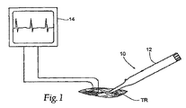
図1は、組織部位TR内において標的にされる神経線維または枝の存在を区別および/または識別するシステム10を示す。システム10は、刺激電流を生成しかつ標的にされる神経線維または枝の部位TRにおいて組織に刺激電流を印加する第1のデバイス12を含む。システム10はまた、電気的刺激電流の印加に対する予期される生理的応答の有無を感知する第2のデバイス14を含む。予期される生理的応答の存在は、組織部位TR内における標的にされる神経線維または枝の存在を区別および/または識別する。標的にされる神経線維または枝は、一旦区別および識別されると、所望の診断および/または治療の理由により処置され得る。
(Description of Preferred Embodiment)
(I. System)
FIG. 1 illustrates a
(A.第1のデバイス)
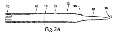
図2A〜図4が示すように、第1のデバイス12は、好ましくは、懐中電燈またはねじ回しのように保持されかつ用いられるほど十分に小さいサイズであり、刺激電流の印加を制御するために親指がボタンを押すことを可能にするハンドル16を含む(図4を参照されたい)。ハンドル16は、絶縁されたプローブ18を保持する。プローブ18は、その遠位端に電極アセンブリ20を保持する(図3Aを参照されたい)。第1のデバイス12は、好ましくは、殺菌した単一使用目的の計器である。
(A. First device)
As FIG. 2A-4 shows, the
代表的な実施形態において、ハンドル16は、円筒形の形状であり、その近位端において約25mmの最大直径を有する。ハンドル16は、近位端から遠位端に向って先細であり、約10mmのより小さな直径となっている。代表的に実施形態において、ハンドル16の長さは約17cmである。
In an exemplary embodiment, the
代表的な実施形態において、プローブ18は、ハンドル16の遠位端から約8cm延び、その遠位端において電極アセンブリ20を含む。代表的な実施形態において、プローブ18は、約10mmの直径を有する。
In the exemplary embodiment,
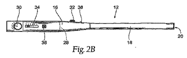
電極アセンブリ20(図3Aを参照されたい)は、標的にされる神経によって神経支配される組織部位を正確に識別するようなサイズでありかつ識別するように構成される。電極アセンブリ20は、歯鏡のようなものに似ているように構成され得、約10mm〜約15mmの範囲内の直径を有し得る。アセンブリ20は、プローブ18からいくらかオフセットされ得(例えば、10度〜50度)、使用の容易さおよびより人間工学的な構成を提供し得る。電極アセンブリ20は、プローブ18の遠位面26において露出した2つの接触子22および24の二極性アレイを備え得る。接触子22および24は、約1mm〜約3mmの範囲内の直径を有し得、遠位面から1mm以内突き出得る。遠位面26における接触子22と24との間の間隔は、約1mm〜約4mmであり得る。接触子22および24の縁は、望ましくは、組織を傷つけないように丸くされる。接触子22および24の小領域は、近くにある刺激に応ずる組織を刺激する高電流密度を確実にする。
Electrode assembly 20 (see FIG. 3A) is sized and configured to accurately identify the tissue site innervated by the targeted nerve. The
電極アセンブリに関する他の構成が可能であり得ることは理解されるべきである。例えば、図3Bおよび図3Cは、2つのさらなる可能な構成を示す。図3Bは、プローブ18の遠位面46において露出する接触子42および44を有する電極アセンブリ40を示す。接触子42および44は、周囲に180度離れて間隔を空けて置かれる。示されるように、接触子42および44は、プローブ18の遠位面46において露出され、その各々は、プローブ18の遠位面46の周囲の約90度〜約95度を占有する。接触子42および44はまた、望ましくは、プローブに沿って近接して約5mm延び、かつ、プローブ18の遠位面46を越えて短い距離、例えば、1mm突き出る。遠位面46における接触子42と44との間の間隔は、約1mm〜約4mmであり得る。接触子42および44の縁は、望ましくは、組織を傷つけないように丸くされる。図3Cは、プローブ18の遠位面56において露出される外側接触子52および内側接触子54を有するリング電極アセンブリを示す。外側接触子52はまたプローブに沿って近接して延びる。
It should be understood that other configurations for the electrode assembly may be possible. For example, FIGS. 3B and 3C show two additional possible configurations. FIG. 3B shows an
接触子22および24(ならびにそれらの代替の実施形態)は、例えば、ステンレス鋼、銀、白金、または白金黒で処理された白金を備え得る。プローブ18は、特にその遠位面26において、プラスチック材料を備え、該プラスチック材料は、直接の組織接触が存在しないとき体液経路を通って電流を通す危険を最小限にするように、血液、食塩水、および体液によってあまり濡れていないことが好ましい。プローブ18は、一般的な絶縁手段(例えば、ワイヤ絶縁、ワッシャ、ガスケット、スペーサ、ブッシングなど)を用いてハンドル16から絶縁される。
あるいは、単極性配置が用いられ得る。この配置において、リターン電極(すなわち、中立電極)は、本体から計器に戻る電気的経路を提供するために備えられなければならない。リターン電極は、無傷な皮膚の表面(例えば、外科的処置中のECG監視に用いられるような表面電極)に配置され得るか、または針状で、術野に配置されるかもしくは無傷の皮膚を貫通し得る。 Alternatively, a unipolar configuration can be used. In this arrangement, a return electrode (ie, a neutral electrode) must be provided to provide an electrical path from the body back to the instrument. The return electrode can be placed on the surface of the intact skin (eg, a surface electrode as used for ECG monitoring during a surgical procedure) or is needle-shaped and placed on the surgical field or on the intact skin. Can penetrate.
電気的刺激制御回路28は、ハンドル16内に保持される(図2Aおよび図2Bを参照されたい)。制御回路28は、接触子22および24を介して印加される刺激電流を生成する。制御回路28は、ハンドル16内に置かれる1次電池(単一の使用用途用)によって作動される。計器が単一使用目的を意図されない場合、電池は再充電可能であり得る。
The electrical
制御回路28は、望ましくは、埋込みコードを保持する搭載されたプログラマブルマイクロプロセッサを含む。コードは、所望の電気的刺激波形を生成するためのプリプログラムされた規則またはアルゴリズムを表す。代表的な実施形態において、刺激周波数は20Hzであり(但し、周波数は、例えば、3Hz〜100Hzに調整可能であり得る)、波形は、電荷平衡二相波形(charge balanced biphasic waveform)を備えている(すなわち、正味直流電流なし)。
The
制御回路28の他の動作パラメータは、ハンドル16上に便利なように保持されるつまみによって調節され得る。
Other operating parameters of the
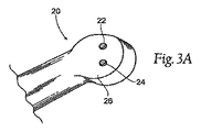
例示される実施形態において(図2Aを参照されたい)、刺激振幅および刺激パルス継続時間は、ハンドル16の近位端の近くまたはその上にあるロータリスイッチ30もしくはホイールによって調整される。ロータリ制御スイッチ30は、望ましくは、複数の設定オプションを識別するためのラベル付けを有する。例えば、最初のいくらかの設定は、種々の振幅であってその各々が同じ固定のパルス継続時間を有する振幅を含み得る。さらなる設定は、振幅とパルス継続時間との特定の組合せを含む選択可能な設定の範囲を提供し得る。ロータリ制御スイッチ30はまた、望ましくは、1つの設定から次の設定に移動するとき、臨床医に良好な触知可能なフィードバックを与える移動止めを有する。ラベル付けされた刺激設定の範囲は、例えば、OFF、STANDBY、100μsecにおける1.5mA、100μsecにおける3mA、100μsecにおける5mA、300μsecにおける5mA、および500μsecにおける10mAを備え得る。
In the illustrated embodiment (see FIG. 2A), the stimulation amplitude and stimulation pulse duration are adjusted by a
例えば親指によるアクセスのための、例えばハウジング16の側にある瞬間押しボタン(momentary pushbutton)32は、接触子22および24を介する刺激電流の伝達を制御する。瞬間押しボタン32は、例えば、片手のみで刺激電流をオンおよびオフにするなど、第1のデバイス12が制御されることを可能にする。押しボタン32が押された場合のみ、刺激電流は、接触子22および24を介して伝達される(ロータリスイッチ30によって設定される振幅/継続時間で)。瞬間押しボタン32が押されない場合、刺激電流は伝達されない。
A
代替の実施形態において(図2Bを参照されたい)、刺激パルス継続時間は、ハンドル16上の調整可能なステップスライドスイッチ34によって調節され得る。従って、瞬間押しボタン32が押された場合、刺激電流が、調節された振幅および調節された継続時間で印加される。押しボタン32が押されない場合、刺激電流は伝達されない。スライドスイッチ34は、望ましくは、選択されたパルス継続時間を識別するためのラベル付けを有する。スライドスイッチ34はまた、望ましくは、1つのパルス継続時間レベルから次のレベルに移動するとき、臨床医に良好な触知可能なフィードバックを与える移動止めを有する。ラベル付けされたパルス継続時間設定の範囲は、例えば、OFF、100μsec、300μsec、または500μsecを備え得る。スライドスイッチ34はまた、ラベル付けされたSTANDBY位置を有し得る。
In an alternative embodiment (see FIG. 2B), the stimulation pulse duration can be adjusted by an adjustable
あるいは、パルス継続時間スライドスイッチ34が備えられず、パルス継続時間がロータリ制御スイッチ30によって選択されていない場合、刺激パルス継続時間は、例えば、250μsecなどの名目上選択された継続時間において固定され得る。
Alternatively, if the pulse
制御回路28は、望ましくは、光指示、すなわち、ハンドル上の発光ダイオードLED38を含み、該LEDは臨床医に様々な指示を提供する。例えば、LED38は、電池の状態および刺激器のON/OFF状態を確認し得る。また望ましくは、適切な刺激が伝達されているとき、緑に光り、適切でない刺激が伝達されているとき、赤に光り得る。さらに、実際に伝達される電流が要求される振幅の所望の割合内、例えば、要求値の25%以内である場合、LED38は、光るかまたは明るくなり得る。それによって、制御回路28は、刺激電流の要求される伝達に関して、信頼できるフィードバックを臨床医に提供する。
The
代替の実施形態において、制御回路28はまた、刺激電流が伝達されているときのみ、音声を生成し得る。音声はハンドル16上の指示機36によって伝導される。
In an alternative embodiment, the
種々の音声、色、種々の光り速度などが用いられるが、制御回路28は、プローブが組織と接触していること、計器がONになっていること、電池が十分な電力を有すること、および刺激電流が流れていることを臨床医が確認することを可能にする。従って、臨床医は、所望の反応を引き出すことができない原因が、リターン電極の接続不備または何か他の計器の問題であるよりはむしろ、プローブの先端近くの生命力のある神経組織の欠如からであるというはるかに大きな確信を有する。
Various voices, colors, various light speeds, etc. are used, but the
(B.第2のデバイス)
第2のデバイス14は、標的にされる組織部位の生理的機能、および第1のデバイス12による電気的刺激電流の印加により予期される生理的反応の性質および性格によって、様々な形態をとり得る。
(B. Second device)
The
例えば、呼吸活動に影響を及ぼす副交感神経の電気的刺激は、呼吸を遅くさせる。従って、呼吸活動に影響を及ぼす副交感神経の有無を区別および/または識別することが所望されるとき、呼吸速度の減少は予期される生理的反応として用いられ得る。この配置において、第2のデバイス14は呼吸を監視する計器を備え得る。計器は、例えば、胸部の動きを監視する胸部位置センサおよび肺活量計箱を備え得る。計器はまた、呼吸センサを備え得、該呼吸センサは、呼吸(伸張)センサまたは呼吸運動記録器などのように胸部の回りに身につけられる。第2のデバイスによって検出される呼吸速度の減少は、第1のデバイスが副交感神経またはその近くに位置していることを示す。
For example, electrical stimulation of the parasympathetic nerve that affects respiratory activity slows breathing. Thus, when it is desired to distinguish and / or identify the presence or absence of parasympathetic nerves that affect respiratory activity, a reduction in respiratory rate can be used as an expected physiological response. In this arrangement, the
別の例として、心臓機能に影響を及ぼす副交感神経の刺激は、静止電位を増加させ、拡張期脱分極の速度を減少させる。これらの状況の下で、心臓速度は遅くなる。従って、従って、心臓活動に影響を及ぼす副交感神経の有無を区別および/または識別することが所望されるとき、心臓速度は予期される生理的反応として用いられ得る。この配置において、第2のデバイス14は心電図(EKG)計器を備え得る。
As another example, parasympathetic stimulation that affects cardiac function increases resting potential and decreases the rate of diastolic depolarization. Under these circumstances, the heart rate is slowed down. Thus, when it is desired to distinguish and / or identify the presence or absence of parasympathetic nerves that affect cardiac activity, cardiac velocity can be used as an expected physiological response. In this arrangement, the
別の例として、消化に影響を及ぼす副交感神経の刺激は(例えば、胃液分泌の頭位段階(cephalic phase)時に)、反射胃液分泌をもたらす。従って、胃活動に影響を及ぼす副交感神経の有無を区別および/または識別することが所望されるとき、胃液の分泌の減少は予期される生理的反応として用いられ得る。この配置において、第2のデバイス14は、胃液の分泌を感知する計器を備え得る。
As another example, parasympathetic stimulation that affects digestion (eg, during the cephalic phase of gastric secretion) results in reflex gastric secretion. Thus, when it is desired to distinguish and / or identify the presence or absence of parasympathetic nerves that affect gastric activity, a decrease in gastric juice secretion can be used as an expected physiological response. In this arrangement, the
別の例として、第2のデバイス14は、筋電図(EMG)計器を備え得る。EMG計器は、筋肉内の神経インパルスを測定する。EMGシステムは、副交感神経によって刺激される組織部位の筋肉に配置される電極を含み、第1のデバイス12の操作に対する電子的反応は、電流の動きを表示する計器(例えば、オシロスコープ)を用いて観察され得る。筋肉が収縮すると、筋肉は弱い電気信号を発し、該電気信号は予期される生理的反応として検出、増幅、および追跡され得る。
As another example, the
(III.システムの使用法)
使用時、第1のデバイス12は、標的にされる組織部位TRにおける組織に接触して配置される。臨床医は、第1のデバイス12を片手で操作し、刺激電流を印加し得る。臨床医の他方の手は、次いで、必要に応じ刺激電流に対する調整を行なうために用いられ得る。第2のデバイス14は、生理的反応を監視する。第2のデバイス14によって示される監視される生理的反応が予期される生理的反応に一致または近似するまで、第1のデバイス12は配置および再配置される(必要な場合)。このことは、標的にされる神経線維または枝の存在を示し、識別された位置は次いで印がつけられ得る。次いで、所望の治療方式が行なわれ得、例えば、治療上の利益のために副交感神経系を処置する。
(III. How to use the system)
In use, the
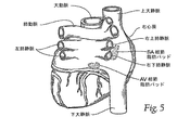
例えば、心臓の副交感神経系は、組織剥離がなくかつ生理的伝導を妨害することなく、心房細動に関係する心臓の伝導およびまたは機能を調和させるように処置され得ることが観察された。迷走神経の副交感神経線維は、心房周期長に影響を及ぼすように処置され得ることが公知である。迷走神経の副交感神経線維は、心外膜房室(AV)結節脂肪パッドおよび洞房(SA)結節脂肪パッドを選択的に刺激することも公知である(図5が示すように)。 For example, it has been observed that the parasympathetic nervous system of the heart can be treated to coordinate cardiac conduction and / or function related to atrial fibrillation without tissue detachment and without disturbing physiological conduction. It is known that vagus parasympathetic fibers can be treated to affect atrial cycle length. Vascular parasympathetic nerve fibers are also known to selectively stimulate epicardial atrioventricular (AV) and sinoatrial (SA) node fat pads (as FIG. 5 shows).
システム10は、例えば、心臓の表面上の心外膜AV結節脂肪パッドの区別および識別を可能にし、それによって、治療上の利益のためにこの位置における心臓の副交感神経系にアクセスすることを可能にする。
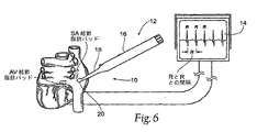
より詳細には、第2のデバイス14が心臓速度を監視しながら、システム10の第1のデバイス12は、非常に特定された電気刺激を心臓の表面に加えることを可能にする。臨床医は、最低の振幅設定において刺激電流の印加を開始し、必要に応じて振幅設定を増加し得る。患者ごとの組織部位の生理的相違により調整が必要であり得る。組織部位TRの視覚検査がより高い初期設定が必要であり得ることを示した後に、臨床医はまた、最低の振幅設定以外のどれかで刺激電流の印加を開始し得る。
More particularly, the
第1のデバイス12が、AV結節脂肪パッドの部位またはその近くに刺激を加え、最終的にそこに位置するとき(図7を参照されたい)、心臓速度(第2のデバイス、例えば、EKG計器によって監視される)は減少する。EKG計器14は、EKGにおいて観察されるRとRとの間隔の増加による心臓速度の減少を示す(図6に示されるRとRとの間隔と図7に示されるRとRとの増加した間隔とを比較されたい)。臨床医は、次いで、組織部位、例えば、識別されたAV結節脂肪パッドへの刺激電流の印加を停止し、元の心臓速度に戻る心臓速度の増加を観察し得る(EKGに観察されるRとRとの間隔の減少)。臨床医は、刺激電流を印加すること、RとRとの間隔の増加を観察すること、刺激電流の印加を停止すること、およびRとRとの間隔の減少を観察することの手段を行い、標的にされる組織部位、例えば、AV結節脂肪パッドの正確な位置を確認し得る。このようにして、システム10は、臨床医が心臓の表面におけるAV結節脂肪パッド(および、副交感神経によって選択的に神経支配される他の部位)を体系的かつ正確に突き止めることを可能にする。
When the
一旦突き止められると、臨床医は、第1のデバイス12を用い、色素(die)または他のマーカを当て、AV結節脂肪パッドの識別を維持し得る。あるいは、色素もしくは他のマーカを当てるために別個のアプリケータが用いられ得るか、または、臨床医は、例えば、自分の指と共に視覚の技能を用い、AV結節脂肪パッドの識別を維持し得る。臨床医は、次いで、治療上の利益のために心臓の副交感神経系を撹乱する手段をとり得る。例えば、システム10によって突き止められたAV結節脂肪パッドの電気的または非電気的処置のいずれかによって、臨床医は、制御されない心房細動を治療または防止するかもしくは他の所望の治療を実行し得、または臨床医は、AV結節速度の生理的制御を提供する閉ループフィードバック制御アルゴリズムを適用し得る。
Once located, the clinician can use the
システム10によって突き止められたAV結節脂肪パッドの処置は、生理的伝導を保存する。電気的処置によって、その利益ある効果は即座にオンおよびオフにされ得、しかも効果の減少はない。AV結節脂肪パッドの処置は、心房細動の治療におけるAV結節切除の実行可能な代案を提供し得、該AV結節切除は、生理的伝導を保存せず、代わりに患者をペースメーカーに依存させる。
Treatment of the AV nodular fat pad located by the
前述の事項は、本発明の原理の例示のみとして考えられる。さらに、多数の修正および変更が当業者に容易に思いつくので、示されかつ記述された正にその構造および動作に本発明を限定することは所望されない。好ましい実施形態が記述されたが、詳細は本発明から逸脱することなく変更され得る。 The foregoing is considered as illustrative only of the principles of the invention. Further, since numerous modifications and changes will readily occur to those skilled in the art, it is not desired to limit the invention to the exact construction and operation shown and described. While preferred embodiments have been described, details may be changed without departing from the invention.
Claims (12)
組織部位に電気的刺激電流を印加する電極構成を含むハンドヘルド計器であって、該ハンドヘルド計器は、ハンドルと、該ハンドル内に保持される電気的刺激制御回路と、該ハンドル上に保持され、かつ該制御回路の少なくとも1つの動作パラメータを選択的に変更するための該制御回路に連結された少なくとも1つの制御器とを含む、ハンドヘルド計器と、
該電気的刺激電流の有無に対して生理的反応を示す第2のデバイスと
を備えている、システム。 A system for distinguishing and / or identifying a targeted tissue site that is locally innervated by a targeted nerve,
A handheld instrument comprising an electrode configuration for applying an electrical stimulation current to a tissue site, the handheld instrument being retained on the handle, an electrical stimulation control circuit retained in the handle, and A handheld instrument comprising: at least one controller coupled to the control circuit for selectively changing at least one operating parameter of the control circuit;
A second device that exhibits a physiological response to the presence or absence of the electrical stimulation current.
請求項1に記載されるシステムを用いて、副交感神経によって神経支配される、心臓上の脂肪パッド部位を突き止めることと、
診断または治療上の利益のために、該脂肪パッドの部位における該心臓の副交感神経系を処置することと
を包含する、方法。 A method of treating the heart,
Using the system of claim 1 to locate a fat pad site on the heart that is innervated by parasympathetic nerves;
Treating the parasympathetic nervous system of the heart at the site of the fat pad for diagnostic or therapeutic benefit.
電気的刺激を加えることと、
該電気的刺激の加えることに対する生理的反応を観察することと、
該電気的刺激の加えることを停止することと、
該電気的刺激の加えることを停止することに対する生理的反応を観測することと
をさらに包含する、請求項10に記載の方法。 To find out
Applying electrical stimulation,
Observing a physiological response to the application of the electrical stimulus;
Stopping applying the electrical stimulus;
11. The method of claim 10, further comprising: observing a physiological response to stopping applying the electrical stimulus.
Applications Claiming Priority (2)
| Application Number | Priority Date | Filing Date | Title |
|---|---|---|---|
| US11/337,319 US20060200219A1 (en) | 2005-03-01 | 2006-01-23 | Systems and methods for differentiating and/or identifying tissue regions innervated by targeted nerves for diagnostic and/or therapeutic purposes |
| PCT/US2007/001259 WO2007117344A2 (en) | 2006-01-23 | 2007-01-18 | Differentiating and/or identifying tissue regions innervated by targeted nerves |
Publications (2)
| Publication Number | Publication Date |
|---|---|
| JP2009523544A true JP2009523544A (en) | 2009-06-25 |
| JP2009523544A5 JP2009523544A5 (en) | 2011-03-03 |
Family
ID=38581535
Family Applications (1)
| Application Number | Title | Priority Date | Filing Date |
|---|---|---|---|
| JP2008551363A Pending JP2009523544A (en) | 2006-01-23 | 2007-01-18 | Systems and methods for differentiating and / or identifying tissue sites stimulated by targeted nerves for diagnostic and / or therapeutic purposes |
Country Status (7)
| Country | Link |
|---|---|
| US (1) | US20060200219A1 (en) |
| EP (1) | EP1993440A4 (en) |
| JP (1) | JP2009523544A (en) |
| CN (2) | CN101528123B (en) |
| AU (1) | AU2007235595A1 (en) |
| CA (1) | CA2637958A1 (en) |
| WO (1) | WO2007117344A2 (en) |
Cited By (1)
| Publication number | Priority date | Publication date | Assignee | Title |
|---|---|---|---|---|
| JP2020528770A (en) * | 2017-06-05 | 2020-10-01 | パウエル マンスフィールド, インコーポレイテッド | Penetration sensor for assessing neuromuscular function |
Families Citing this family (83)
| Publication number | Priority date | Publication date | Assignee | Title |
|---|---|---|---|---|
| US8914114B2 (en) | 2000-05-23 | 2014-12-16 | The Feinstein Institute For Medical Research | Inhibition of inflammatory cytokine production by cholinergic agonists and vagus nerve stimulation |
| US8073538B2 (en) | 2003-11-13 | 2011-12-06 | Cardio Polymers, Inc. | Treatment of cardiac arrhythmia by modification of neuronal signaling through fat pads of the heart |
| WO2005092308A2 (en) | 2004-03-25 | 2005-10-06 | The Feinstein Institute For Medical Research | Neural tourniquet |
| US10912712B2 (en) | 2004-03-25 | 2021-02-09 | The Feinstein Institutes For Medical Research | Treatment of bleeding by non-invasive stimulation |
| US20100331883A1 (en) | 2004-10-15 | 2010-12-30 | Schmitz Gregory P | Access and tissue modification systems and methods |
| US20110190772A1 (en) * | 2004-10-15 | 2011-08-04 | Vahid Saadat | Powered tissue modification devices and methods |
| US8613745B2 (en) | 2004-10-15 | 2013-12-24 | Baxano Surgical, Inc. | Methods, systems and devices for carpal tunnel release |
| US7578819B2 (en) | 2005-05-16 | 2009-08-25 | Baxano, Inc. | Spinal access and neural localization |
| US7857813B2 (en) | 2006-08-29 | 2010-12-28 | Baxano, Inc. | Tissue access guidewire system and method |
| US8221397B2 (en) | 2004-10-15 | 2012-07-17 | Baxano, Inc. | Devices and methods for tissue modification |
| JP5243034B2 (en) | 2004-10-15 | 2013-07-24 | バクサノ,インク. | Tissue removal device |
| US9247952B2 (en) | 2004-10-15 | 2016-02-02 | Amendia, Inc. | Devices and methods for tissue access |
| US8048080B2 (en) | 2004-10-15 | 2011-11-01 | Baxano, Inc. | Flexible tissue rasp |
| US8430881B2 (en) | 2004-10-15 | 2013-04-30 | Baxano, Inc. | Mechanical tissue modification devices and methods |
| US9101386B2 (en) | 2004-10-15 | 2015-08-11 | Amendia, Inc. | Devices and methods for treating tissue |
| JP2008525102A (en) | 2004-12-27 | 2008-07-17 | ノース ショア−ロング アイランド ジューウィッシュ リサーチ インスティテュート | Treatment of inflammatory disorders by electrical vagus nerve stimulation |
| US11207518B2 (en) | 2004-12-27 | 2021-12-28 | The Feinstein Institutes For Medical Research | Treating inflammatory disorders by stimulation of the cholinergic anti-inflammatory pathway |
| US20120296442A1 (en) * | 2005-03-01 | 2012-11-22 | Checkpoint Surgical, Llc | Systems and methods for intra-operative physiological functional stimulation |
| US7878981B2 (en) * | 2005-03-01 | 2011-02-01 | Checkpoint Surgical, Llc | Systems and methods for intra-operative stimulation |
| US20110060238A1 (en) * | 2005-03-01 | 2011-03-10 | Checkpoint Surgical, Llc | Systems and methods for intra-operative physiological functional stimulation |
| US20110060243A1 (en) * | 2005-03-01 | 2011-03-10 | Checkpoint Surgical, Llc | Systems and methods for intra-operative regional neural stimulation |
| US10154792B2 (en) | 2005-03-01 | 2018-12-18 | Checkpoint Surgical, Inc. | Stimulation device adapter |
| US20110054346A1 (en) * | 2005-03-01 | 2011-03-03 | Checkpoint Surgical, Llc | Systems and methods for Intra-operative semi-quantitative threshold neural response testing related applications |
| US7896815B2 (en) * | 2005-03-01 | 2011-03-01 | Checkpoint Surgical, Llc | Systems and methods for intra-operative stimulation |
| US20110060242A1 (en) * | 2005-03-01 | 2011-03-10 | Checkpoint Surgical, Llc | Systems and methods for intra-operative stimulation within a surgical field |
| US9861836B2 (en) * | 2005-06-16 | 2018-01-09 | Biosense Webster, Inc. | Less invasive methods for ablation of fat pads |
| US8366712B2 (en) | 2005-10-15 | 2013-02-05 | Baxano, Inc. | Multiple pathways for spinal nerve root decompression from a single access point |
| US8062298B2 (en) | 2005-10-15 | 2011-11-22 | Baxano, Inc. | Flexible tissue removal devices and methods |
| US7725188B2 (en) | 2006-02-10 | 2010-05-25 | Electrocore Llc | Electrical stimulation treatment of hypotension |
| US9126050B2 (en) * | 2009-03-20 | 2015-09-08 | ElectroCore, LLC | Non-invasive vagus nerve stimulation devices and methods to treat or avert atrial fibrillation |
| US8041428B2 (en) | 2006-02-10 | 2011-10-18 | Electrocore Llc | Electrical stimulation treatment of hypotension |
| US7742819B2 (en) | 2006-11-07 | 2010-06-22 | Boston Scientific Neuromodulation Corporation | System and method for uniformly displacing a region of neural stimulation |
| US8374673B2 (en) | 2007-01-25 | 2013-02-12 | Warsaw Orthopedic, Inc. | Integrated surgical navigational and neuromonitoring system having automated surgical assistance and control |
| US7987001B2 (en) | 2007-01-25 | 2011-07-26 | Warsaw Orthopedic, Inc. | Surgical navigational and neuromonitoring instrument |
| US8391970B2 (en) | 2007-08-27 | 2013-03-05 | The Feinstein Institute For Medical Research | Devices and methods for inhibiting granulocyte activation by neural stimulation |
| EP2194861A1 (en) * | 2007-09-06 | 2010-06-16 | Baxano, Inc. | Method, system and apparatus for neural localization |
| US8192436B2 (en) | 2007-12-07 | 2012-06-05 | Baxano, Inc. | Tissue modification devices |
| WO2009146030A1 (en) | 2008-03-31 | 2009-12-03 | The Feinstein Institute For Medical Research | Methods and systems for reducing inflammation by neuromodulation of t-cell activity |
| US9662490B2 (en) | 2008-03-31 | 2017-05-30 | The Feinstein Institute For Medical Research | Methods and systems for reducing inflammation by neuromodulation and administration of an anti-inflammatory drug |
| US9314253B2 (en) | 2008-07-01 | 2016-04-19 | Amendia, Inc. | Tissue modification devices and methods |
| US8398641B2 (en) | 2008-07-01 | 2013-03-19 | Baxano, Inc. | Tissue modification devices and methods |
| US8409206B2 (en) * | 2008-07-01 | 2013-04-02 | Baxano, Inc. | Tissue modification devices and methods |
| CA2730732A1 (en) | 2008-07-14 | 2010-01-21 | Baxano, Inc. | Tissue modification devices |
| DE102008038908A1 (en) * | 2008-08-13 | 2010-02-18 | Universitätsklinikum Heidelberg | Suction device for aspirating fluid during a surgical procedure |
| WO2010059617A2 (en) | 2008-11-18 | 2010-05-27 | Setpoint Medical Corporation | Devices and methods for optimizing electrode placement for anti-inflamatory stimulation |
| CA2749673A1 (en) * | 2009-03-13 | 2010-09-16 | Baxano, Inc. | Flexible neural localization devices and methods |
| US8996116B2 (en) | 2009-10-30 | 2015-03-31 | Setpoint Medical Corporation | Modulation of the cholinergic anti-inflammatory pathway to treat pain or addiction |
| US9211410B2 (en) | 2009-05-01 | 2015-12-15 | Setpoint Medical Corporation | Extremely low duty-cycle activation of the cholinergic anti-inflammatory pathway to treat chronic inflammation |
| AU2010258792B2 (en) | 2009-06-09 | 2015-07-02 | Setpoint Medical Corporation | Nerve cuff with pocket for leadless stimulator |
| US8394102B2 (en) | 2009-06-25 | 2013-03-12 | Baxano, Inc. | Surgical tools for treatment of spinal stenosis |
| US9833621B2 (en) | 2011-09-23 | 2017-12-05 | Setpoint Medical Corporation | Modulation of sirtuins by vagus nerve stimulation |
| US11051744B2 (en) | 2009-11-17 | 2021-07-06 | Setpoint Medical Corporation | Closed-loop vagus nerve stimulation |
| WO2011079309A2 (en) | 2009-12-23 | 2011-06-30 | Setpoint Medical Corporation | Neural stimulation devices and systems for treatment of chronic inflammation |
| CN102652670A (en) * | 2011-03-01 | 2012-09-05 | 三维医疗科技江苏股份有限公司 | Neurophysiological male sexual function detector |
| CN103619405B (en) | 2011-05-09 | 2015-11-25 | 赛博恩特医疗器械公司 | The individual pulse being used for the treatment of the cholinergic anti-inflammatory pathway of chronic inflammatory disease activates |
| US20130245490A1 (en) * | 2011-09-08 | 2013-09-19 | Checkpoint Surgical, Llc | System for providing targeted electrical stimulation to tissue |
| US8646921B2 (en) | 2011-11-30 | 2014-02-11 | Izi Medical Products | Reflective marker being radio-opaque for MRI |
| US8661573B2 (en) | 2012-02-29 | 2014-03-04 | Izi Medical Products | Protective cover for medical device having adhesive mechanism |
| US9572983B2 (en) | 2012-03-26 | 2017-02-21 | Setpoint Medical Corporation | Devices and methods for modulation of bone erosion |
| US9439598B2 (en) | 2012-04-12 | 2016-09-13 | NeuroMedic, Inc. | Mapping and ablation of nerves within arteries and tissues |
| NZ704579A (en) | 2013-04-19 | 2018-10-26 | Oculeve Inc | Nasal stimulation devices and methods |
| ES2951944T3 (en) * | 2013-07-23 | 2023-10-25 | Ivoclar Vivadent Ag | Light curing device for dental restoration materials |
| US10123731B2 (en) | 2014-08-08 | 2018-11-13 | Medtronic Xomed, Inc. | Wireless sensors for nerve integrity monitoring systems |
| US10231778B2 (en) * | 2014-10-20 | 2019-03-19 | Biosense Webster (Israel) Ltd. | Methods for contemporaneous assessment of renal denervation |
| US11311725B2 (en) | 2014-10-24 | 2022-04-26 | Setpoint Medical Corporation | Systems and methods for stimulating and/or monitoring loci in the brain to treat inflammation and to enhance vagus nerve stimulation |
| WO2016126807A1 (en) | 2015-02-03 | 2016-08-11 | Setpoint Medical Corporation | Apparatus and method for reminding, prompting, or alerting a patient with an implanted stimulator |
| CN107847740A (en) * | 2015-02-24 | 2018-03-27 | 加尔瓦尼生物电子有限公司 | Nerve modulation equipment |
| US20160287112A1 (en) * | 2015-04-03 | 2016-10-06 | Medtronic Xomed, Inc. | System And Method For Omni-Directional Bipolar Stimulation Of Nerve Tissue Of A Patient Via A Bipolar Stimulation Probe |
| US10596367B2 (en) | 2016-01-13 | 2020-03-24 | Setpoint Medical Corporation | Systems and methods for establishing a nerve block |
| CN114904142A (en) | 2016-01-20 | 2022-08-16 | 赛博恩特医疗器械公司 | Control of vagal nerve stimulation |
| US11471681B2 (en) | 2016-01-20 | 2022-10-18 | Setpoint Medical Corporation | Batteryless implantable microstimulators |
| EP3405255A4 (en) | 2016-01-20 | 2019-10-16 | Setpoint Medical Corporation | Implantable microstimulators and inductive charging systems |
| US10583304B2 (en) | 2016-01-25 | 2020-03-10 | Setpoint Medical Corporation | Implantable neurostimulator having power control and thermal regulation and methods of use |
| US10252048B2 (en) | 2016-02-19 | 2019-04-09 | Oculeve, Inc. | Nasal stimulation for rhinitis, nasal congestion, and ocular allergies |
| AU2017339255B2 (en) * | 2016-10-05 | 2022-04-14 | Innovative Surgical Solutions, Llc | Neural locating and mapping |
| EP3668402A4 (en) | 2017-08-14 | 2021-05-19 | Setpoint Medical Corporation | Vagus nerve stimulation pre-screening test |
| CN107468237B (en) * | 2017-08-24 | 2024-02-13 | 郭铮蔚 | Multifunctional nerve monitoring exploration system and implementation method thereof |
| CN111511435A (en) | 2017-10-25 | 2020-08-07 | 艾品诺龙科技公司 | Systems and methods for delivering neuroregenerative therapy |
| US10589089B2 (en) | 2017-10-25 | 2020-03-17 | Epineuron Technologies Inc. | Systems and methods for delivering neuroregenerative therapy |
| US11260229B2 (en) | 2018-09-25 | 2022-03-01 | The Feinstein Institutes For Medical Research | Methods and apparatuses for reducing bleeding via coordinated trigeminal and vagal nerve stimulation |
| US11247043B2 (en) | 2019-10-01 | 2022-02-15 | Epineuron Technologies Inc. | Electrode interface devices for delivery of neuroregenerative therapy |
| US11938324B2 (en) | 2020-05-21 | 2024-03-26 | The Feinstein Institutes For Medical Research | Systems and methods for vagus nerve stimulation |
| CN113133745A (en) * | 2021-04-30 | 2021-07-20 | 中南大学湘雅二医院 | Sympathetic nerve chain nerve fiber positioning and mapping device |
Citations (11)
| Publication number | Priority date | Publication date | Assignee | Title |
|---|---|---|---|---|
| US4962766A (en) * | 1989-07-19 | 1990-10-16 | Herzon Garrett D | Nerve locator and stimulator |
| JPH09215757A (en) * | 1996-02-09 | 1997-08-19 | Medtronic Inc | Device for medical use for processing upper airway fault |
| JP2002528039A (en) * | 1996-01-19 | 2002-08-27 | ボストン・サイエンティフィック・リミテッド | Heat ablation system and method for tissue using porous electrode structure |
| JP2003503119A (en) * | 1999-06-25 | 2003-01-28 | エモリ ユニバーシティ | Vagal nerve stimulation device and method |
| JP2003520110A (en) * | 2000-01-10 | 2003-07-02 | トランスニューロニックス インコーポレイテッド | Electrode device used in laparoscopic surgery |
| JP2004500917A (en) * | 2000-04-27 | 2004-01-15 | メドトロニック・インコーポレーテッド | Suction-stabilized epicardial resection device |
| JP2004508875A (en) * | 2000-09-22 | 2004-03-25 | ティシューリンク・メディカル・インコーポレーテッド | Liquid assisted medical device |
| WO2004075974A2 (en) * | 2003-02-25 | 2004-09-10 | Leptos Biomedical, Inc. | Splanchnic nerve stimulation for treatment of obesity |
| JP2004275427A (en) * | 2003-03-14 | 2004-10-07 | Terumo Corp | Heart treatment equipment |
| JP2005525861A (en) * | 2002-05-16 | 2005-09-02 | ティシューリンク メディカル インコーポレイテッド | Fluid assisted medical devices, systems and methods. |
| WO2005112813A1 (en) * | 2004-05-17 | 2005-12-01 | C.R. Bard, Inc. | Method and apparatus for mapping and7or ablation of cardiac tissue |
Family Cites Families (48)
| Publication number | Priority date | Publication date | Assignee | Title |
|---|---|---|---|---|
| US4305402A (en) * | 1979-06-29 | 1981-12-15 | Katims Jefferson J | Method for transcutaneous electrical stimulation |
| US4545374A (en) * | 1982-09-03 | 1985-10-08 | Jacobson Robert E | Method and instruments for performing a percutaneous lumbar diskectomy |
| US4515168A (en) * | 1983-07-22 | 1985-05-07 | Chester Martin H | Clamp-on nerve stimulator and locator |
| US4616660A (en) * | 1984-12-10 | 1986-10-14 | Suncoast Medical Manufacturing, Inc. | Variable alternating current output nerve locator/stimulator |
| US4817628A (en) * | 1985-10-18 | 1989-04-04 | David L. Zealear | System and method for evaluating neurological function controlling muscular movements |
| US4777960A (en) * | 1986-08-18 | 1988-10-18 | Massachusetts Institute Of Technology | Method and apparatus for the assessment of autonomic response by broad-band excitation |
| DE3719353A1 (en) * | 1987-06-10 | 1988-12-22 | Sterimed Gmbh | ELECTRIC STIMULATOR FOR NERVES |
| US5086788A (en) * | 1988-06-13 | 1992-02-11 | Castel John C | Hand-held physiological stimulation applicator |
| US5012816A (en) * | 1989-08-31 | 1991-05-07 | Gabor Lederer | Electronic acupuncture device |
| US5046506A (en) * | 1990-02-09 | 1991-09-10 | Singer Medical Products, Inc. | Molded needle with adhesive |
| US6159194A (en) * | 1992-01-07 | 2000-12-12 | Arthrocare Corporation | System and method for electrosurgical tissue contraction |
| US5284153A (en) * | 1992-04-14 | 1994-02-08 | Brigham And Women's Hospital | Method for locating a nerve and for protecting nerves from injury during surgery |
| CN2212966Y (en) * | 1994-03-09 | 1995-11-22 | 戴品忠 | Hand-held electrocardiogram analyzer |
| US5540235A (en) * | 1994-06-30 | 1996-07-30 | Wilson; John R. | Adaptor for neurophysiological monitoring with a personal computer |
| US5775331A (en) * | 1995-06-07 | 1998-07-07 | Uromed Corporation | Apparatus and method for locating a nerve |
| US5779642A (en) * | 1996-01-16 | 1998-07-14 | Nightengale; Christopher | Interrogation device and method |
| US6473511B1 (en) * | 1996-03-14 | 2002-10-29 | Sarnoff Corporation | Disposable hearing aid with integral power source |
| US7035384B1 (en) * | 1996-04-17 | 2006-04-25 | Convergys Cmg Utah, Inc. | Call processing system with call screening |
| US5879289A (en) * | 1996-07-15 | 1999-03-09 | Universal Technologies International, Inc. | Hand-held portable endoscopic camera |
| US5853373A (en) * | 1996-08-05 | 1998-12-29 | Becton, Dickinson And Company | Bi-level charge pulse apparatus to facilitate nerve location during peripheral nerve block procedures |
| US6091995A (en) * | 1996-11-08 | 2000-07-18 | Surx, Inc. | Devices, methods, and systems for shrinking tissues |
| US6542260B1 (en) * | 1997-01-13 | 2003-04-01 | Hewlett-Packard Company | Multiple image scanner |
| US5928158A (en) * | 1997-03-25 | 1999-07-27 | Aristides; Arellano | Medical instrument with nerve sensor |
| US6654634B1 (en) * | 1997-12-16 | 2003-11-25 | Richard L. Prass | Method and apparatus for connection of stimulus and recording electrodes of a multi-channel nerve integrity monitoring system |
| US6292701B1 (en) * | 1998-08-12 | 2001-09-18 | Medtronic Xomed, Inc. | Bipolar electrical stimulus probe with planar electrodes |
| US6139545A (en) * | 1998-09-09 | 2000-10-31 | Vidaderm | Systems and methods for ablating discrete motor nerve regions |
| US6304785B1 (en) * | 1998-10-27 | 2001-10-16 | Huntington Medical Research Institute | Electrode insertion tool |
| US6334068B1 (en) * | 1999-09-14 | 2001-12-25 | Medtronic Xomed, Inc. | Intraoperative neuroelectrophysiological monitor |
| EP1237472A4 (en) * | 1999-11-24 | 2008-04-30 | Nuvasive Inc | Electromyography system |
| US6612983B1 (en) * | 2000-03-28 | 2003-09-02 | Medtronic, Inc. | Pancreatic secretion response to stimulation test protocol |
| US6312392B1 (en) * | 2000-04-06 | 2001-11-06 | Garrett D. Herzon | Bipolar handheld nerve locator and evaluator |
| US6494882B1 (en) * | 2000-07-25 | 2002-12-17 | Verimetra, Inc. | Cutting instrument having integrated sensors |
| US6564079B1 (en) * | 2000-07-27 | 2003-05-13 | Ckm Diagnostics, Inc. | Electrode array and skin attachment system for noninvasive nerve location and imaging device |
| WO2002032504A2 (en) * | 2000-10-20 | 2002-04-25 | The Government Of The United States Of America, As Represented By The Secretary Of The Department Of Health And Human Services | Coil for magnetic stimulation |
| WO2002034330A2 (en) * | 2000-10-26 | 2002-05-02 | Medtronic, Inc. | Method and apparatus to minimize the effects of a cardiac insult |
| DE10054405A1 (en) * | 2000-11-02 | 2002-05-29 | Heinz Koszlat | Rolling and massage electrode for use in neurology, acupuncture and non-medical healing treatments, is designed for easy use and easy exchange of roller electrodes |
| US6618626B2 (en) * | 2001-01-16 | 2003-09-09 | Hs West Investments, Llc | Apparatus and methods for protecting the axillary nerve during thermal capsullorhaphy |
| US7778711B2 (en) * | 2001-08-31 | 2010-08-17 | Bio Control Medical (B.C.M.) Ltd. | Reduction of heart rate variability by parasympathetic stimulation |
| EP2481338A3 (en) * | 2001-09-25 | 2012-09-05 | Nuvasive, Inc. | System for performing surgical procedures and assessments |
| US6829508B2 (en) * | 2001-10-19 | 2004-12-07 | Alfred E. Mann Foundation For Scientific Research | Electrically sensing and stimulating system for placement of a nerve stimulator or sensor |
| WO2004021959A2 (en) * | 2002-09-04 | 2004-03-18 | Urmey William F | Positioning system for a nerve stimulator needle |
| US7010352B2 (en) * | 2002-12-11 | 2006-03-07 | The Mcw Research Foundation, Inc. | Transcutaneous electrical nerve locator |
| WO2005030318A1 (en) * | 2003-09-25 | 2005-04-07 | Nuvasive, Inc. | Surgical access system and related methods |
| US7418292B2 (en) * | 2003-10-01 | 2008-08-26 | Medtronic, Inc. | Device and method for attenuating an immune response |
| US7555347B2 (en) * | 2004-04-09 | 2009-06-30 | Alfred E. Mann Institute For Biomedical Engineering At The University Of Southern California | Identification of target site for implantation of a microstimulator |
| US20050256541A1 (en) * | 2004-04-30 | 2005-11-17 | Medtronic, Inc. | Catheter with temporary stimulation electrode |
| TWI233872B (en) * | 2004-07-15 | 2005-06-11 | New Sun Far East Corp Ltd | Hand tool having warning function |
| US10342452B2 (en) * | 2004-07-29 | 2019-07-09 | Medtronic Xomed, Inc. | Stimulator handpiece for an evoked potential monitoring system |
-
2006
- 2006-01-23 US US11/337,319 patent/US20060200219A1/en not_active Abandoned
-
2007
- 2007-01-18 JP JP2008551363A patent/JP2009523544A/en active Pending
- 2007-01-18 EP EP07769187A patent/EP1993440A4/en not_active Withdrawn
- 2007-01-18 CN CN2007800063418A patent/CN101528123B/en not_active Expired - Fee Related
- 2007-01-18 CA CA002637958A patent/CA2637958A1/en not_active Abandoned
- 2007-01-18 AU AU2007235595A patent/AU2007235595A1/en not_active Abandoned
- 2007-01-18 WO PCT/US2007/001259 patent/WO2007117344A2/en active Application Filing
- 2007-01-18 CN CN2012100063285A patent/CN102553072A/en active Pending
Patent Citations (11)
| Publication number | Priority date | Publication date | Assignee | Title |
|---|---|---|---|---|
| US4962766A (en) * | 1989-07-19 | 1990-10-16 | Herzon Garrett D | Nerve locator and stimulator |
| JP2002528039A (en) * | 1996-01-19 | 2002-08-27 | ボストン・サイエンティフィック・リミテッド | Heat ablation system and method for tissue using porous electrode structure |
| JPH09215757A (en) * | 1996-02-09 | 1997-08-19 | Medtronic Inc | Device for medical use for processing upper airway fault |
| JP2003503119A (en) * | 1999-06-25 | 2003-01-28 | エモリ ユニバーシティ | Vagal nerve stimulation device and method |
| JP2003520110A (en) * | 2000-01-10 | 2003-07-02 | トランスニューロニックス インコーポレイテッド | Electrode device used in laparoscopic surgery |
| JP2004500917A (en) * | 2000-04-27 | 2004-01-15 | メドトロニック・インコーポレーテッド | Suction-stabilized epicardial resection device |
| JP2004508875A (en) * | 2000-09-22 | 2004-03-25 | ティシューリンク・メディカル・インコーポレーテッド | Liquid assisted medical device |
| JP2005525861A (en) * | 2002-05-16 | 2005-09-02 | ティシューリンク メディカル インコーポレイテッド | Fluid assisted medical devices, systems and methods. |
| WO2004075974A2 (en) * | 2003-02-25 | 2004-09-10 | Leptos Biomedical, Inc. | Splanchnic nerve stimulation for treatment of obesity |
| JP2004275427A (en) * | 2003-03-14 | 2004-10-07 | Terumo Corp | Heart treatment equipment |
| WO2005112813A1 (en) * | 2004-05-17 | 2005-12-01 | C.R. Bard, Inc. | Method and apparatus for mapping and7or ablation of cardiac tissue |
Cited By (1)
| Publication number | Priority date | Publication date | Assignee | Title |
|---|---|---|---|---|
| JP2020528770A (en) * | 2017-06-05 | 2020-10-01 | パウエル マンスフィールド, インコーポレイテッド | Penetration sensor for assessing neuromuscular function |
Also Published As
| Publication number | Publication date |
|---|---|
| CN101528123A (en) | 2009-09-09 |
| EP1993440A2 (en) | 2008-11-26 |
| CN101528123B (en) | 2012-03-14 |
| US20060200219A1 (en) | 2006-09-07 |
| WO2007117344A3 (en) | 2008-11-13 |
| EP1993440A4 (en) | 2010-02-24 |
| CN102553072A (en) | 2012-07-11 |
| AU2007235595A1 (en) | 2007-10-18 |
| CA2637958A1 (en) | 2007-10-18 |
| WO2007117344A2 (en) | 2007-10-18 |
Similar Documents
| Publication | Publication Date | Title |
|---|---|---|
| JP2009523544A (en) | Systems and methods for differentiating and / or identifying tissue sites stimulated by targeted nerves for diagnostic and / or therapeutic purposes | |
| US11576599B2 (en) | Stimulation device adapter | |
| US11654082B2 (en) | Auricular peripheral nerve field stimulator and method of operating same | |
| ES2352144T3 (en) | DEVICE FOR DIAGNOSING AND TREATING NEURONAL DYSFUNCTION. | |
| JP6902464B2 (en) | Selective nerve fiber blocking methods and systems | |
| CA2946791C (en) | Catheter and catheter system for electrical neuromodulation | |
| JP2009523544A5 (en) | ||
| CN107708795A (en) | Improve the system and method for HRV | |
| US20180250510A1 (en) | Monitoring and stimulation module | |
| US10675465B2 (en) | Methods for treatment of disease using galvanic vestibular stimulation | |
| CN111511435A (en) | Systems and methods for delivering neuroregenerative therapy | |
| CA2924050C (en) | Stimulation device adapter | |
| US10569084B2 (en) | Method and system for altering body mass composition using galvanic vestibular stimulation | |
| CN105492066B (en) | For stimulating diathermic method and apparatus | |
| US10052257B2 (en) | Method and apparatus for stimulative electrotherapy | |
| JP2020512065A (en) | Delivery system for internal smooth muscle stimulation | |
| US20240099632A1 (en) | Nerve stimulation patterns and device for detectability of nerve function and health |
Legal Events
| Date | Code | Title | Description |
|---|---|---|---|
| A521 | Written amendment |
Free format text: JAPANESE INTERMEDIATE CODE: A523 Effective date: 20100115 |
|
| A621 | Written request for application examination |
Free format text: JAPANESE INTERMEDIATE CODE: A621 Effective date: 20100115 |
|
| A521 | Written amendment |
Free format text: JAPANESE INTERMEDIATE CODE: A523 Effective date: 20110111 |
|
| A711 | Notification of change in applicant |
Free format text: JAPANESE INTERMEDIATE CODE: A711 Effective date: 20110413 |
|
| A131 | Notification of reasons for refusal |
Free format text: JAPANESE INTERMEDIATE CODE: A131 Effective date: 20120104 |
|
| A521 | Written amendment |
Free format text: JAPANESE INTERMEDIATE CODE: A523 Effective date: 20120330 |
|
| A02 | Decision of refusal |
Free format text: JAPANESE INTERMEDIATE CODE: A02 Effective date: 20120522 |