JP2009522132A - Micro stripe film - Google Patents
Micro stripe film Download PDFInfo
- Publication number
- JP2009522132A JP2009522132A JP2008548527A JP2008548527A JP2009522132A JP 2009522132 A JP2009522132 A JP 2009522132A JP 2008548527 A JP2008548527 A JP 2008548527A JP 2008548527 A JP2008548527 A JP 2008548527A JP 2009522132 A JP2009522132 A JP 2009522132A
- Authority
- JP
- Japan
- Prior art keywords
- film
- thermoplastic polymer
- regions
- layer
- region
- Prior art date
- Legal status (The legal status is an assumption and is not a legal conclusion. Google has not performed a legal analysis and makes no representation as to the accuracy of the status listed.)
- Withdrawn
Links
Images


Classifications
-
- B—PERFORMING OPERATIONS; TRANSPORTING
- B32—LAYERED PRODUCTS
- B32B—LAYERED PRODUCTS, i.e. PRODUCTS BUILT-UP OF STRATA OF FLAT OR NON-FLAT, e.g. CELLULAR OR HONEYCOMB, FORM
- B32B27/00—Layered products comprising a layer of synthetic resin
- B32B27/06—Layered products comprising a layer of synthetic resin as the main or only constituent of a layer, which is next to another layer of the same or of a different material
- B32B27/08—Layered products comprising a layer of synthetic resin as the main or only constituent of a layer, which is next to another layer of the same or of a different material of synthetic resin
-
- B—PERFORMING OPERATIONS; TRANSPORTING
- B29—WORKING OF PLASTICS; WORKING OF SUBSTANCES IN A PLASTIC STATE IN GENERAL
- B29C—SHAPING OR JOINING OF PLASTICS; SHAPING OF MATERIAL IN A PLASTIC STATE, NOT OTHERWISE PROVIDED FOR; AFTER-TREATMENT OF THE SHAPED PRODUCTS, e.g. REPAIRING
- B29C48/00—Extrusion moulding, i.e. expressing the moulding material through a die or nozzle which imparts the desired form; Apparatus therefor
- B29C48/03—Extrusion moulding, i.e. expressing the moulding material through a die or nozzle which imparts the desired form; Apparatus therefor characterised by the shape of the extruded material at extrusion
- B29C48/07—Flat, e.g. panels
- B29C48/08—Flat, e.g. panels flexible, e.g. films
-
- B—PERFORMING OPERATIONS; TRANSPORTING
- B29—WORKING OF PLASTICS; WORKING OF SUBSTANCES IN A PLASTIC STATE IN GENERAL
- B29C—SHAPING OR JOINING OF PLASTICS; SHAPING OF MATERIAL IN A PLASTIC STATE, NOT OTHERWISE PROVIDED FOR; AFTER-TREATMENT OF THE SHAPED PRODUCTS, e.g. REPAIRING
- B29C48/00—Extrusion moulding, i.e. expressing the moulding material through a die or nozzle which imparts the desired form; Apparatus therefor
- B29C48/16—Articles comprising two or more components, e.g. co-extruded layers
- B29C48/18—Articles comprising two or more components, e.g. co-extruded layers the components being layers
- B29C48/21—Articles comprising two or more components, e.g. co-extruded layers the components being layers the layers being joined at their surfaces
-
- B—PERFORMING OPERATIONS; TRANSPORTING
- B29—WORKING OF PLASTICS; WORKING OF SUBSTANCES IN A PLASTIC STATE IN GENERAL
- B29C—SHAPING OR JOINING OF PLASTICS; SHAPING OF MATERIAL IN A PLASTIC STATE, NOT OTHERWISE PROVIDED FOR; AFTER-TREATMENT OF THE SHAPED PRODUCTS, e.g. REPAIRING
- B29C48/00—Extrusion moulding, i.e. expressing the moulding material through a die or nozzle which imparts the desired form; Apparatus therefor
- B29C48/25—Component parts, details or accessories; Auxiliary operations
- B29C48/30—Extrusion nozzles or dies
- B29C48/305—Extrusion nozzles or dies having a wide opening, e.g. for forming sheets
- B29C48/307—Extrusion nozzles or dies having a wide opening, e.g. for forming sheets specially adapted for bringing together components, e.g. melts within the die
-
- B—PERFORMING OPERATIONS; TRANSPORTING
- B32—LAYERED PRODUCTS
- B32B—LAYERED PRODUCTS, i.e. PRODUCTS BUILT-UP OF STRATA OF FLAT OR NON-FLAT, e.g. CELLULAR OR HONEYCOMB, FORM
- B32B25/00—Layered products comprising a layer of natural or synthetic rubber
- B32B25/16—Layered products comprising a layer of natural or synthetic rubber comprising polydienes homopolymers or poly-halodienes homopolymers
-
- B—PERFORMING OPERATIONS; TRANSPORTING
- B32—LAYERED PRODUCTS
- B32B—LAYERED PRODUCTS, i.e. PRODUCTS BUILT-UP OF STRATA OF FLAT OR NON-FLAT, e.g. CELLULAR OR HONEYCOMB, FORM
- B32B27/00—Layered products comprising a layer of synthetic resin
- B32B27/12—Layered products comprising a layer of synthetic resin next to a fibrous or filamentary layer
-
- B—PERFORMING OPERATIONS; TRANSPORTING
- B32—LAYERED PRODUCTS
- B32B—LAYERED PRODUCTS, i.e. PRODUCTS BUILT-UP OF STRATA OF FLAT OR NON-FLAT, e.g. CELLULAR OR HONEYCOMB, FORM
- B32B27/00—Layered products comprising a layer of synthetic resin
- B32B27/30—Layered products comprising a layer of synthetic resin comprising vinyl (co)polymers; comprising acrylic (co)polymers
- B32B27/302—Layered products comprising a layer of synthetic resin comprising vinyl (co)polymers; comprising acrylic (co)polymers comprising aromatic vinyl (co)polymers, e.g. styrenic (co)polymers
-
- B—PERFORMING OPERATIONS; TRANSPORTING
- B32—LAYERED PRODUCTS
- B32B—LAYERED PRODUCTS, i.e. PRODUCTS BUILT-UP OF STRATA OF FLAT OR NON-FLAT, e.g. CELLULAR OR HONEYCOMB, FORM
- B32B27/00—Layered products comprising a layer of synthetic resin
- B32B27/32—Layered products comprising a layer of synthetic resin comprising polyolefins
-
- B—PERFORMING OPERATIONS; TRANSPORTING
- B32—LAYERED PRODUCTS
- B32B—LAYERED PRODUCTS, i.e. PRODUCTS BUILT-UP OF STRATA OF FLAT OR NON-FLAT, e.g. CELLULAR OR HONEYCOMB, FORM
- B32B3/00—Layered products comprising a layer with external or internal discontinuities or unevennesses, or a layer of non-planar form; Layered products having particular features of form
- B32B3/10—Layered products comprising a layer with external or internal discontinuities or unevennesses, or a layer of non-planar form; Layered products having particular features of form characterised by a discontinuous layer, i.e. formed of separate pieces of material
-
- B—PERFORMING OPERATIONS; TRANSPORTING
- B32—LAYERED PRODUCTS
- B32B—LAYERED PRODUCTS, i.e. PRODUCTS BUILT-UP OF STRATA OF FLAT OR NON-FLAT, e.g. CELLULAR OR HONEYCOMB, FORM
- B32B3/00—Layered products comprising a layer with external or internal discontinuities or unevennesses, or a layer of non-planar form; Layered products having particular features of form
- B32B3/26—Layered products comprising a layer with external or internal discontinuities or unevennesses, or a layer of non-planar form; Layered products having particular features of form characterised by a particular shape of the outline of the cross-section of a continuous layer; characterised by a layer with cavities or internal voids ; characterised by an apertured layer
- B32B3/263—Layered products comprising a layer with external or internal discontinuities or unevennesses, or a layer of non-planar form; Layered products having particular features of form characterised by a particular shape of the outline of the cross-section of a continuous layer; characterised by a layer with cavities or internal voids ; characterised by an apertured layer characterised by a layer having non-uniform thickness
-
- B—PERFORMING OPERATIONS; TRANSPORTING
- B32—LAYERED PRODUCTS
- B32B—LAYERED PRODUCTS, i.e. PRODUCTS BUILT-UP OF STRATA OF FLAT OR NON-FLAT, e.g. CELLULAR OR HONEYCOMB, FORM
- B32B5/00—Layered products characterised by the non- homogeneity or physical structure, i.e. comprising a fibrous, filamentary, particulate or foam layer; Layered products characterised by having a layer differing constitutionally or physically in different parts
- B32B5/02—Layered products characterised by the non- homogeneity or physical structure, i.e. comprising a fibrous, filamentary, particulate or foam layer; Layered products characterised by having a layer differing constitutionally or physically in different parts characterised by structural features of a fibrous or filamentary layer
- B32B5/022—Non-woven fabric
-
- B—PERFORMING OPERATIONS; TRANSPORTING
- B32—LAYERED PRODUCTS
- B32B—LAYERED PRODUCTS, i.e. PRODUCTS BUILT-UP OF STRATA OF FLAT OR NON-FLAT, e.g. CELLULAR OR HONEYCOMB, FORM
- B32B5/00—Layered products characterised by the non- homogeneity or physical structure, i.e. comprising a fibrous, filamentary, particulate or foam layer; Layered products characterised by having a layer differing constitutionally or physically in different parts
- B32B5/14—Layered products characterised by the non- homogeneity or physical structure, i.e. comprising a fibrous, filamentary, particulate or foam layer; Layered products characterised by having a layer differing constitutionally or physically in different parts characterised by a layer differing constitutionally or physically in different parts, e.g. denser near its faces
- B32B5/142—Variation across the area of the layer
-
- B—PERFORMING OPERATIONS; TRANSPORTING
- B32—LAYERED PRODUCTS
- B32B—LAYERED PRODUCTS, i.e. PRODUCTS BUILT-UP OF STRATA OF FLAT OR NON-FLAT, e.g. CELLULAR OR HONEYCOMB, FORM
- B32B7/00—Layered products characterised by the relation between layers; Layered products characterised by the relative orientation of features between layers, or by the relative values of a measurable parameter between layers, i.e. products comprising layers having different physical, chemical or physicochemical properties; Layered products characterised by the interconnection of layers
- B32B7/02—Physical, chemical or physicochemical properties
- B32B7/022—Mechanical properties
-
- B—PERFORMING OPERATIONS; TRANSPORTING
- B29—WORKING OF PLASTICS; WORKING OF SUBSTANCES IN A PLASTIC STATE IN GENERAL
- B29C—SHAPING OR JOINING OF PLASTICS; SHAPING OF MATERIAL IN A PLASTIC STATE, NOT OTHERWISE PROVIDED FOR; AFTER-TREATMENT OF THE SHAPED PRODUCTS, e.g. REPAIRING
- B29C48/00—Extrusion moulding, i.e. expressing the moulding material through a die or nozzle which imparts the desired form; Apparatus therefor
- B29C48/03—Extrusion moulding, i.e. expressing the moulding material through a die or nozzle which imparts the desired form; Apparatus therefor characterised by the shape of the extruded material at extrusion
- B29C48/13—Articles with a cross-section varying in the longitudinal direction, e.g. corrugated pipes
-
- B—PERFORMING OPERATIONS; TRANSPORTING
- B32—LAYERED PRODUCTS
- B32B—LAYERED PRODUCTS, i.e. PRODUCTS BUILT-UP OF STRATA OF FLAT OR NON-FLAT, e.g. CELLULAR OR HONEYCOMB, FORM
- B32B2250/00—Layers arrangement
- B32B2250/44—Number of layers variable across the laminate
-
- B—PERFORMING OPERATIONS; TRANSPORTING
- B32—LAYERED PRODUCTS
- B32B—LAYERED PRODUCTS, i.e. PRODUCTS BUILT-UP OF STRATA OF FLAT OR NON-FLAT, e.g. CELLULAR OR HONEYCOMB, FORM
- B32B2270/00—Resin or rubber layer containing a blend of at least two different polymers
-
- B—PERFORMING OPERATIONS; TRANSPORTING
- B32—LAYERED PRODUCTS
- B32B—LAYERED PRODUCTS, i.e. PRODUCTS BUILT-UP OF STRATA OF FLAT OR NON-FLAT, e.g. CELLULAR OR HONEYCOMB, FORM
- B32B2274/00—Thermoplastic elastomer material
-
- B—PERFORMING OPERATIONS; TRANSPORTING
- B32—LAYERED PRODUCTS
- B32B—LAYERED PRODUCTS, i.e. PRODUCTS BUILT-UP OF STRATA OF FLAT OR NON-FLAT, e.g. CELLULAR OR HONEYCOMB, FORM
- B32B37/00—Methods or apparatus for laminating, e.g. by curing or by ultrasonic bonding
- B32B37/14—Methods or apparatus for laminating, e.g. by curing or by ultrasonic bonding characterised by the properties of the layers
- B32B37/15—Methods or apparatus for laminating, e.g. by curing or by ultrasonic bonding characterised by the properties of the layers with at least one layer being manufactured and immediately laminated before reaching its stable state, e.g. in which a layer is extruded and laminated while in semi-molten state
- B32B37/153—Methods or apparatus for laminating, e.g. by curing or by ultrasonic bonding characterised by the properties of the layers with at least one layer being manufactured and immediately laminated before reaching its stable state, e.g. in which a layer is extruded and laminated while in semi-molten state at least one layer is extruded and immediately laminated while in semi-molten state
-
- Y—GENERAL TAGGING OF NEW TECHNOLOGICAL DEVELOPMENTS; GENERAL TAGGING OF CROSS-SECTIONAL TECHNOLOGIES SPANNING OVER SEVERAL SECTIONS OF THE IPC; TECHNICAL SUBJECTS COVERED BY FORMER USPC CROSS-REFERENCE ART COLLECTIONS [XRACs] AND DIGESTS
- Y10—TECHNICAL SUBJECTS COVERED BY FORMER USPC
- Y10T—TECHNICAL SUBJECTS COVERED BY FORMER US CLASSIFICATION
- Y10T428/00—Stock material or miscellaneous articles
- Y10T428/24—Structurally defined web or sheet [e.g., overall dimension, etc.]
- Y10T428/24479—Structurally defined web or sheet [e.g., overall dimension, etc.] including variation in thickness
- Y10T428/24612—Composite web or sheet
Abstract
主として第1の熱可塑性ポリマーから形成される第1組の領域と、主として第2の熱可塑性ポリマーから形成される第2組の領域を交互にサイドバイサイド方式で配置された少なくとも2組の領域を含む共押出しフィルム又はフィルム層が提供される。これらのサイドバイサイドポリマー領域は、一般に連続的に機械方向に延びる。フィルム又はフィルム層は、第1の面と第2の面とを有する。少なくとも片方の面には、第1の熱可塑性ポリマー領域の1つが、もう1つの(第2の熱可塑性ポリマー領域又は第3の熱可塑性ポリマー領域)熱可塑性ポリマー領域の隣接したレーンにまたがって第1の面上に第1の熱可塑性ポリマーの連続層を形成する。反対側の面が、少なくとも部分的に他方の熱可塑性ポリマーを含む。第1の熱可塑性ポリマーのこのブリッジング層は、相容化剤又は結束層(tie layer)を必要とせずに機械方向に対して横断方向にフィルム又はフィルム層の一体性を維持し、他方の熱可塑性ポリマー領域が第2の面上に露出することを可能にする。 Including at least two sets of regions alternately arranged in a side-by-side manner with a first set of regions formed primarily from a first thermoplastic polymer and a second set of regions formed primarily from a second thermoplastic polymer A coextruded film or film layer is provided. These side-by-side polymer regions generally extend continuously in the machine direction. The film or film layer has a first surface and a second surface. On at least one side, one of the first thermoplastic polymer regions is spanned across the adjacent lane of the other (second thermoplastic polymer region or third thermoplastic polymer region) thermoplastic polymer region. A continuous layer of a first thermoplastic polymer is formed on one side. The opposite surface at least partially comprises the other thermoplastic polymer. This bridging layer of the first thermoplastic polymer maintains the integrity of the film or film layer in a direction transverse to the machine direction without the need for compatibilizers or tie layers, Allows the thermoplastic polymer region to be exposed on the second surface.
Description
本発明は、異なる熱可塑性ポリマーの比較的に接近して間隔をあけたサイドバイサイドゾーンを有するフィルムに関する。 The present invention relates to a film having relatively closely spaced side-by-side zones of different thermoplastic polymers.
熱可塑性材料のサイドバイサイドゾーンを有するフィルムを記載するかなりの件数の特許が存在する。これらのフィルムは、一般にポリマー類の共押出成形によって形成されるとして記載されている。使用されるポリマー類が、それらがポリマー界面において強い固着を形成するように、密接に相容性であればこの方法についてなんらの問題もない。しかしながら、熱可塑性ポリマーの多数の異なる組み合わせが、相容性でないか若しくはほとんど相互の接着特性を有しない点において、共押出しの問題が起こる。もし熱可塑性ポリマーのこれらの組み合わせが、サイドバイサイド構成で共押出しされるならば、それらは多くの場合ポリマー界面において容易に分離することができ横断方向(押出し方向に対して横断する方向)においてフィルムを極めて弱いものにする。米国特許第6,211,483号及び第6,669,887号は、熱可塑性不弾性ポリマーとともにサイドバイサイド方式で共押出しされる熱可塑性エラストマーを記載している。これらの2つの異なる種類のポリマー間の付着強度を向上させるために、改良された相互付着特性を有する特殊なポリマー対が選択される。具体的には、テトラブロックSEPSEPが、エンドブロック補強樹脂とブレンドされるときにポリオレフィンに接着強度の向上を呈示するとして記載された。相容化剤がまた好ましくは使用される。 There are a significant number of patents describing films having side-by-side zones of thermoplastic material. These films are generally described as being formed by coextrusion of polymers. There is no problem with this method if the polymers used are closely compatible so that they form a strong bond at the polymer interface. However, the problem of coextrusion arises in that many different combinations of thermoplastic polymers are not compatible or have little mutual adhesive properties. If these combinations of thermoplastic polymers are coextruded in a side-by-side configuration, they can often be easily separated at the polymer interface and the film in the transverse direction (the direction transverse to the extrusion direction). Make it extremely weak. US Pat. Nos. 6,211,483 and 6,669,887 describe thermoplastic elastomers that are coextruded in a side-by-side manner with a thermoplastic inelastic polymer. In order to improve the bond strength between these two different types of polymers, special polymer pairs with improved inter-adhesion properties are selected. Specifically, tetrablock SEPSEP was described as exhibiting improved adhesion strength to polyolefins when blended with endblock reinforcing resins. Compatibilizers are also preferably used.
サイドバイサイド共押出しはまた米国特許出願公開第2005/0060849 A1号に記載されている。この場合、接合強度の問題は直接には扱われていないが、検討を必要とする1つの問題として認識されている。この問題は、もし相溶性が問題であるならば、相溶化剤がポリマー(高分子)材料へ追加又は結束層が使用されるべきあり、若しくは不相溶性ポリマーのサイドバイサイド領域が担体基材上へ押し出されるべきであると記載され単に扱われている。後者の場合において担体基材は、サイドバイサイド層がそれらの相互の接合面において分離しないように維持する強度を提供する。 Side-by-side coextrusion is also described in US Patent Application Publication No. 2005/0060849 A1. In this case, the problem of bonding strength is not directly handled, but is recognized as one problem that needs to be examined. The problem is that if compatibility is an issue, a compatibilizer should be added to the polymer (polymer) material or a tie layer should be used, or the side-by-side region of the incompatible polymer would be on the carrier substrate. It is described and simply treated as being to be extruded. In the latter case, the carrier substrate provides the strength to keep the side-by-side layers from separating at their mutual interface.
米国特許第5,620,780号;第5,773,374号及び第5,429,856号は、弾性材料のコアが非弾性材料によって完全に取り囲まれている共押出しされた材料を記載している。分離が島又は連続ストライプ又はストランドの形態にある弾性体を備える非弾性材料の連続相によって防止され、相溶性の問題が存在するとしても、これは弾性及び非弾性特性を有するゾーンを形成することができる。 US Pat. Nos. 5,620,780; 5,773,374 and 5,429,856 describe co-extruded materials in which the core of elastic material is completely surrounded by inelastic material. ing. Separation is prevented by a continuous phase of inelastic material comprising an elastic body in the form of islands or continuous stripes or strands, which forms zones with elastic and inelastic properties, even if there are compatibility problems Can do.
熱可塑性ポリマーのサイドバイサイド領域を有するフィルムを提供することが望ましく、これは化学修飾剤、追加の結束層又は支持体を必要とせずに直接に形成できる。具体的には、押出しダイ内に直接に形成でき且つポリマー界面において領域間剥離のほとんどない横断方向弾性を有する弾性及び非弾性材料の連続サイドバイサイド領域を有するフィルムを形成することが望ましいであろう。 It is desirable to provide a film having a side-by-side region of thermoplastic polymer, which can be formed directly without the need for chemical modifiers, additional tie layers or supports. In particular, it would be desirable to form films having continuous side-by-side regions of elastic and inelastic materials that can be formed directly in an extrusion die and have transverse elasticity at the polymer interface with little delamination between regions.
本発明の共押出しフィルム又はフィルム層は、主として第1の熱可塑性ポリマーから形成される第1組の領域と、主として第2の熱可塑性ポリマーから形成される第2組の領域とが交互にサイドバイサイド方式に配置された、少なくとも2組の領域を含む。これらのサイドバイサイドポリマー領域は、一般に連続的に機械方向に延びる。このフィルム又はフィルム層は、第1の面と、第2の面とを有する。少なくとも片方面上で、第1の熱可塑性ポリマーの領域の片方が、もう1つの(第2の熱可塑性ポリマー領域又は第3の熱可塑性ポリマー領域)熱可塑性ポリマー領域の隣接したレーンにまたがって第1の面上に第1の熱可塑性ポリマーの連続層を形成する。この反対側の面は、他方の熱可塑性ポリマーを少なくとも部分的に含む。第1の熱可塑性ポリマーのブリッジング層は、相容化剤又は結束層を必要とせずに機械方向に対して横断方向にフィルム又はフィルム層の一体性を維持し、及び他方の熱可塑性ポリマー領域が第2の面上に露出されることを可能にする。 The co-extruded film or film layer of the present invention has side-by-side alternating first sets of regions formed primarily from a first thermoplastic polymer and second sets of regions formed primarily from a second thermoplastic polymer. It includes at least two sets of regions arranged in a manner. These side-by-side polymer regions generally extend continuously in the machine direction. This film or film layer has a first surface and a second surface. On at least one side, one of the regions of the first thermoplastic polymer spans an adjacent lane of another (second thermoplastic polymer region or third thermoplastic polymer region) thermoplastic polymer region. A continuous layer of a first thermoplastic polymer is formed on one side. This opposite surface at least partially comprises the other thermoplastic polymer. The bridging layer of the first thermoplastic polymer maintains the integrity of the film or film layer in a direction transverse to the machine direction without the need for a compatibilizer or tie layer, and the other thermoplastic polymer region Can be exposed on the second surface.
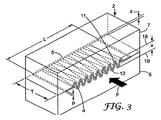
本発明の共押出しフィルム(用語「フィルム」はまた、本明細書で使用する時、多層フィルムの中のフィルム層を言うことができる)を形成する方法に使用される押出し装置は、図1に概略的に示される。図1の押出し装置に使用されるダイ1は、図1aに示される。一般に、本発明のフィルムを形成するために使用される方法は、図2及び図3に示すダイインサート2のような、ダイインサート2を通って所定の流路Fに沿って初期多層溶融流(メルトストリーム)を第1に押し出す工程を含む。この所定の流路Fは、好ましくは一次元であり、且つ流路のある部分に沿って連続している。一次元とは、溶融流が直線のような、任意の一次元的線形タイプの形状となりうるが、それは湾曲線とすることもできるであろうし、この曲線がそれ自体交差でき、楕円形状又は円形状(例えば、環状ダイ)を形成できるであろうことを意味する。 The extrusion apparatus used in the method of forming the coextruded film of the present invention (the term “film” can also refer to a film layer in a multilayer film as used herein) is shown in FIG. Shown schematically. A die 1 used in the extrusion apparatus of FIG. 1 is shown in FIG. 1a. In general, the method used to form the film of the present invention is the initial multilayer melt flow along a predetermined flow path F through the die insert 2, such as the die insert 2 shown in FIGS. A step of first extruding a melt stream). The predetermined flow path F is preferably one-dimensional and is continuous along a portion of the flow path. One dimension can be any one-dimensional linear type of shape, such as a straight line of the melt flow, but it could also be a curved line, this curve can itself intersect, an elliptical shape or a circle It means that a shape (eg an annular die) could be formed.
図1に示すように、溶融流は従来式押出機8及び9から放出され少なくとも1つのダイインサート2を有するダイ1を通り、ここでダイインサートは、プロファイル非直線入口開口部4を有し、流路が流路の中心線のいずれの側にも、一連のピーク(山谷)11及び12間に規則的に又は不規則的に波打つ。「非直線」とは、ダイインサート入口開口部4が、全体として矩形形状以外の形状にあることを意味するが、ただしダイ入口開口部では形状を直線とすることができるであろう。このダイインサート入口開口部4は、流入初期溶融流の少なくとも一部を断続し且つ所定の初期溶融流流路形状からダイインサート入口開口部4により画定される単一流路(又は複数流路)形状へこの断続された溶融流の一部の方向を変える。この断続された、方向を変えられた溶融流は、次いでダイインサート2においてダイインサート入口開口部4におけるプロファイル形状からダイインサート出口5までダイインサートによって画定される、全体として集束する流路へ集束する。ダイインサート出口5におけるこの集束された溶融流流路は、形状において元の所定の溶融流流路(例えば、矩形又は一次元)に類似させることができる。この方法に使用されるこのダイインサート2は、少なくとも部分的に横断方向に、初期溶融フローストリームの再分配を生じさせ、流入多層ポリマー溶融流のうちの1層以上のサイドバイサイド型再分配を形成する。ダイインサート出口における溶融流は、次いでフィルムなどのような、物品として押し出される。溶融流とは、ニュートン流体又は粘弾性流体のストリームがダイの出口において押し出され及び固形化できることを意味する。この材料は、溶融相にあってもよいし、そうでなくてもよい。
As shown in FIG. 1, the melt stream is discharged from conventional extruders 8 and 9 and passes through a
上述の実施形態で示されたインサートは、ダイ内に配置された単独の要素である。このインサートはまた、それが記載された機構を有する限りそれが配置されるダイ及び/又はフィードブロックと一体形成できるであろう。用語インサートは、ダイ、フィードブロック若しくは別の構成要素内にあるかどうかに関係なく、プロファイル入口及び記載されたような他の機構を提供する任意の構造体を特定するために使用される。 The insert shown in the above embodiment is a single element placed in the die. This insert could also be integrally formed with the die and / or feedblock in which it is placed as long as it has the described mechanism. The term insert is used to identify any structure that provides a profile entry and other features as described, whether in a die, feed block, or another component.
多層溶融流は、任意の従来の方法によって形成される。共押出しされた多層溶融流は、一般に実質的に一定の厚層の従来の多層フローストリームのような、構造化配置を有するが、ただし、この層の厚さは、ダイ及び又はフィードロックの設計及び/又はポリマーのレオロジー的差異に起因のいずれかで、規則的に又はランダムに変動する可能性がある。既知の多層押出しプロセスとしては、米国特許第5,501,675号;第5,462,708号;第5,354,597号及び第5,344,691号に開示されるプロセスが挙げられ、この内容が参照により本明細書に実質的に組み込まれている。これらの引用文献は、少なくとも1つの弾性層と、1つ又は2つの比較的に非弾性層とを有する多層エラストマー性積層体の様々な形態を教示している。多層フィルムはまた、しかしながら、これらの既知の多層共押出し技術を利用して、2つ以上の弾性層又は2つ以上の非弾性層、若しくはこれらの任意の組み合わせから形成できる。 The multilayer melt flow is formed by any conventional method. A co-extruded multilayer melt stream generally has a structured arrangement, such as a conventional multilayer flow stream of a substantially constant thick layer, provided that the thickness of this layer is determined by the die and / or feed lock design. And / or may vary regularly or randomly, either due to rheological differences in the polymer. Known multilayer extrusion processes include those disclosed in US Pat. Nos. 5,501,675; 5,462,708; 5,354,597 and 5,344,691, This content is substantially incorporated herein by reference. These references teach various forms of multilayer elastomeric laminates having at least one elastic layer and one or two relatively inelastic layers. Multilayer films, however, can also be formed from two or more elastic layers or two or more inelastic layers, or any combination thereof, utilizing these known multilayer coextrusion techniques.
溶融流は、インサートプロファイルによりインサート入口において及びインサート内部で方向を変えられるか若しくは再分配され、その初期非線形又は非直線流路形態(所与の点における流路又はダイキャビティの横断面形状)から実質的により線形又は直線流路形態及び/又は初期の所定の物質(複数)流路に似ることができる流路形態へ集束する。先行溶融流の1つ以上の層を形成するポリマー(類)は、初期の所定の物質流路又は形態に対して少なくとも横断方向に再分配されるか又は方向を変えられる。この方向を変えられた流量は、インサート入口における溶融ストリーム流量の一部分の分裂又は断続によって少なくとも部分的に引き起こされる。この分裂された溶融流は、余り構造化されない形態でインサート内で流路に沿って集束し、これは、例えば、矩形インサート開口部など、初期の溶融流流路形態と類似することができ、1層の少なくとも一部又は初期溶融流の部分が、ダイインサート出口開口部から流出する押し出された材料又はフィルムの幅又は横断方向のように、異なるゾーン又は領域において異なる割合へ分割されている。インサートが、フィードブロックにより接近若しくはフィードブロック内に位置決めされる場合、ポリマー溶融流流路形態は、フィルム状構造体へ余り細長くされず且つ高さと幅の比率がより高い。これは結果的にインサートによって再分配されつつあるポリマー溶解物の比較的に大きなゾーンを生じる。インサートがダイ出口により接近している場合、流入ポリマー溶融流流路形態は高さと幅の比率がより小さいフィルム状形態へより細長くされる。この点におけるインサートは、流入ポリマー溶融フローストリームのより小さい部分を再分配するであろう。これらの2つのタイプのインサートは、組み合わされて同一溶融流上で大規模及び小規模両方のポリマー再分配を可能にする。 The melt flow is redirected or redistributed at the insert inlet and within the insert by the insert profile and from its initial non-linear or non-linear flow path configuration (flow path or die cavity cross-sectional shape at a given point). Focus to a substantially linear or straight channel configuration and / or a channel configuration that can resemble an initial predetermined substance channel. The polymer (s) forming one or more layers of the pre-melt flow is redistributed or redirected at least in the transverse direction relative to the initial predetermined material flow path or configuration. This redirected flow rate is caused at least in part by splitting or interrupting a portion of the melt stream flow rate at the insert inlet. This split melt flow converges along the flow path in the insert in a less structured form, which can be similar to the initial melt flow flow path configuration, for example, a rectangular insert opening, At least a portion of the layer or portion of the initial melt flow is divided into different proportions in different zones or regions, such as the width or transverse direction of the extruded material or film exiting from the die insert exit opening. When the insert is closer or positioned within the feed block, the polymer melt flow channel configuration is not too elongated into the film-like structure and has a higher height to width ratio. This results in a relatively large zone of polymer melt that is being redistributed by the insert. When the insert is closer to the die exit, the incoming polymer melt flow channel configuration is elongated to a film-like configuration with a smaller height to width ratio. The insert at this point will redistribute a smaller portion of the incoming polymer melt flow stream. These two types of inserts are combined to enable both large and small scale polymer redistribution on the same melt stream.
インサート2は、図1aに示すような従来のダイ(コートハンガー(coat hanger)ダイのような)へ容易にはめ込むことができる。一般にインサート2は、図2及び図3に示すように第1及び第2の半分の6と7のように、ダイインサートが複数分解可能構成要素から形成される場合には、簡単に取り外し、取り替え、洗浄することができるこのダイインサートは、保守のために容易に切り離し、洗浄し、そして再び組み立てることができる。複数ダイ構成要素を使用してダイインサートを形成することはまた、より複雑なフローチャネル(流路)が、ワイヤ放電加工(electron discharge wire machining)のような、従来の方法によって形成されることを可能にする。二分割ダイインサートが示されているが、複分割ダイインサートも組み立てダイインサートにおいてより複雑なフローチャネル即ち流路が形成されることを可能にする。このダイインサートはまた、ダイの他の部品とともに全体的に又は部分的に形成することができる。ダイインサート内の流路は、しかしながら、好ましくはそれらがダイ内の流路の少なくとも一部において直線的に先細にするように、実質的に連続であり且つ集束する。 The insert 2 can be easily snapped into a conventional die (such as a coat hanger die) as shown in FIG. 1a. In general, the insert 2 is easily removed and replaced when the die insert is formed from multiple disassembleable components, such as first and second halves 6 and 7 as shown in FIGS. This die insert, which can be cleaned, can be easily detached for maintenance, cleaned and reassembled. Using multiple die components to form die inserts also allows more complex flow channels to be formed by conventional methods such as electron discharge wire machining. enable. Although a two-piece die insert is shown, the two-piece die insert also allows more complex flow channels or channels to be formed in the assembled die insert. The die insert can also be formed in whole or in part with other parts of the die. The flow paths in the die insert, however, are preferably substantially continuous and converging so that they taper linearly in at least a portion of the flow paths in the die.
インサート入口開口部(又はこれらの部分)はまた、インサート入口開口部の断面の外周と同等な矩形ダイインサート開口部(同一の長さL及び同一の平均幅寸法Pを有する開口部)との比率によって特徴づけることができる。本発明のインサート入口開口部の外周と同等矩形インサート入口開口部の外周との比率は、外周比率であり、これは1.1〜10若しくは1.1又は1.5又は2.3より大きくすることができるが、一般には8又は5未満である。より大きな外周又は外周比率を有する構造体は、より高度に構造化された開口部と考えられる。より高度に構造化された開口部であれば、多層又は多成分フローストリームのような、流入初期溶融フローストリームからの溶融流のより劇的な再分配が一般に存在する。これは、一般に所与の断続された流路に取って代わるより多くの流路に原因している。しかしながら、比較的に低いレベルの閉鎖範囲(例えば、ダイ開口部の無い領域x内の範囲)を有する極めて大きな外周比率であれば、極めて少ない溶解物がかなり再分配される。より多くの閉鎖範囲(低いパーセントの開放範囲)は、より高度に構造化された連続開口部又は不連続開口部と特に結合される場合に、流入溶融フローストリームの少なくとも幾つかの部分のより劇的な再分配につながる。 Insert inlet openings (or portions thereof) are also in proportion to rectangular die insert openings (openings having the same length L and the same average width dimension P) that are equivalent to the outer periphery of the cross section of the insert inlet opening. Can be characterized by. The ratio of the outer periphery of the insert inlet opening of the present invention to the outer periphery of the equivalent rectangular insert inlet opening is the outer peripheral ratio, which is greater than 1.1-10 or 1.1 or 1.5 or 2.3. But can generally be less than 8 or 5. A structure with a larger perimeter or perimeter ratio is considered a more highly structured opening. With more highly structured openings, there is generally a more dramatic redistribution of the melt stream from the incoming initial melt flow stream, such as a multi-layer or multi-component flow stream. This is due to more channels that generally replace a given intermittent channel. However, a very large perimeter ratio with a relatively low level of closure range (e.g., a range in region x without the die opening) will significantly redistribute very little lysate. More closed area (low percent open area) is more dramatic in at least some parts of the incoming melt flow stream, especially when combined with more structured continuous or discontinuous openings. Redistribution.
一般に1層又は両層のある種の熱可塑性材料は、溶融フローストリーム内の所与の個所において、代替の流路を見つけることを強制される。高度に構造化された開口部であれば、2つのピーク(11及び12)によって境界をつけられた領域内に様々の独特な可能な流路が存在する。この熱可塑性材料は、平均的な流路から逸脱する多数の可能な流路が存在する場合により容易に分岐される。所与のインサート開口部にあっては、これは2004年12月30日に出願された、同時係属の出願第11/02616号に定義されるような流路偏移係数として定義され、これの全体が参照により組み込まれている。一般にこの偏移係数は、0.2より大きいか、又は0.5より大きく、最大で2又は3であるが、ただし、より高い偏移係数が可能である。より高い偏移係数であれば、上部境界線18と底部境界線19との間で離隔されるより多くの流路が存在する。ダイインサートの出口はまた、ある偏移係数を有することができるが、好ましくは対応する入口よりかなり下回る。一般に出口は、入口より少なくとも50パーセント少、又は80パーセント少の偏移係数を有する。この出口は、最大量の流量再分配を提供し且つ平坦なプロファイルフィルム又は溶融流を形成するために零の偏移係数を有することができる。
In general, certain thermoplastic materials in one or both layers are forced to find an alternative flow path at a given point in the melt flow stream. With a highly structured opening, there are a variety of unique possible flow paths in the region bounded by the two peaks (11 and 12). This thermoplastic material is more easily branched when there are a large number of possible flow paths that deviate from the average flow path. For a given insert opening, this is defined as the channel deviation coefficient as defined in co-pending application No. 11/02616, filed December 30, 2004, All are incorporated by reference. In general, this deviation factor is greater than 0.2 or greater than 0.5 and up to 2 or 3, however, higher deviation factors are possible. With a higher deviation coefficient, there are more channels that are spaced between the
一般に、インサートは入口開口部から実質連続したインサート出口開口部まで先細にする。その流路の幾つかの部分について外側に先細にするチャネル又はダイインサート入口と出口開口部との間で変化するテーパのような、インサート内の代替の先細チャネルがまた可能である。 Generally, the insert tapers from the inlet opening to the substantially continuous insert outlet opening. Alternative tapered channels within the insert are also possible, such as channels that taper outwardly for some portion of the flow path or taper that varies between the die insert inlet and outlet openings.
インサート入口開口部の開口面積は、一般にインサート出口開口部の開口面積より大きく、入口と出口開口部の比率は0.9〜10又は1〜5である。入口面積を出口面積より小さくすることは可能であるが、これはより大きな背圧及びより厚いフィルム構造体を形成させるであろう。 The opening area of the insert inlet opening is generally larger than the opening area of the insert outlet opening, and the ratio of the inlet to the outlet opening is 0.9 to 10 or 1 to 5. Although it is possible for the inlet area to be smaller than the outlet area, this will result in greater back pressure and a thicker film structure.
上述したように、溶融流層は一般に入口開口部(出口幅zによって決定される)まで最短流路をたどり、これは最上の溶融流層については一般にピーク11になり、及び最低の溶融流層についてはピーク12となるであろう。一般に、ポリマー溶融流流量の任意の所与の部分であれば材料は入口4によって提供される最も接近した開口部へ流れる傾向になる。
As mentioned above, the molten fluidized bed generally follows the shortest flow path to the inlet opening (determined by the outlet width z), which generally peaks at 11 for the uppermost molten fluidized bed, and the lowest molten fluidized bed. Will be peak 12. In general, for any given portion of the polymer melt flow rate, the material will tend to flow to the closest opening provided by the
図4は本発明の方法によって形成されるサイドバイサイドフィルムを示す。この最上の溶融流層(図示せず)は、フィルム層109を形成し、これはダイ開口部のピーク11において再分配されて1組の領域109’を形成する。より低いポリマー溶融流層(図示せず)は、再分配して1組の領域108を形成する。この領域108及び109’は、フィルム層109の薄いブリッジングフィルム層109”ポリマー材料ブリッジング隣接領域109’とともにサイドバイサイド型配置になっている。領域109’間のブリッジングフィルム層109”は、それらが別の方法でサイドバイサイド型接合面107においてうまく結合されなくても、サイドバイサイド領域108及び109’の構造一体化を維持する。これは、ブリッジングフィルム109”が0.25ミクロンほども薄くても、正しい。このブリッジングフィルム109”及びフィルム領域109’は、連続していて且つフィルム層109の連続面105を形成する。反対側の面106は、フィルム層109及びポリマー領域108の両方から形成される。理想的にはブリッジングフィルム層109”の厚さは、0.25〜50ミクロン又は1.0〜10ミクロンとなり、及びフィルム総厚さは、15ミクロン〜500ミクロン又は50〜250ミクロンとすることができる。第1の及び第2の領域は、一般に0.1〜10mm幅又は1.0〜5mm幅とすることができる。
FIG. 4 shows a side-by-side film formed by the method of the present invention. This top melt flow layer (not shown) forms a
このブリッジングフィルム層109”は、流量再分配プロセスにおいて形成される。サイドバイサイド領域を形成する最も外側の溶融流層の片方又は他方、若しくは両方が、(図2及び3中の最も接近したピーク(11又は12)のような)ダイインサートの片側上で最も接近した流路へ再分配せず、その代わりに(図2及び図3中の反対側ピーク11又は反対側ピーク12のような)ダイインサートの反対側へ再分配する。これは熱可塑性材料の溶融強度に原因すると考えられている。これは一般に極めて薄いブリッジングフィルムであり且つ大きな強度を有することはないであろう。しかしながら、この薄いブリッジング領域はおもいがけずサイドバイサイドフィルム構造体全体に対して、横断方向において、有意の強度をもたらす。
This
一般に溶融層は、押出品の幅方向延伸部に沿って分割されるので2つの(又はそれ以上の)溶融流層の割合が押出品幅にわたって変動する。本発明の2層実施形態では、この変動は、材料の実質的に完全な分割が存在して少なくとも1つのフィルム層が隣接領域間で薄いブリッジングフィルムを形成するようなものである。3領域以上の溶融流層であれば、フィルム層の少なくとも1層は、一般に押出品の横方向にわたって厚さが変動しブリッジングフィルム層を形成する。厚さが変動するフィルム層は、一般に押出品の総厚の0〜90%を構成する。フィルム層のいずれもが、押出品の幅(x方向)にわたって任意の点で押出品の総厚の0〜100%を構成することができる。厚さが変動するこのフィルム層は、一般に最も厚い領域を最も薄い領域と比較して少なくとも10パーセント変動、若しくは別の選択肢として、少なくとも20パーセント又は少なくとも50パーセント変動する。この分割は、先行溶融流層の相対的な割合及びインサート4の開口部の形状により要求される。図2及び3に示すような、規則的に波打つ開口部を有するインサートであれば、分割は(溶融流にわたって材料の比較的に一定した等しい層厚を有する共押出しされた多層溶融流を想定して)結果的に図4又は図5に示すようなフィルムを生じる。図5は、図4のフィルム押出成形ないしは別の方法で不織布層へ積層されたものである。本発明のフィルムの利点は、不織布又は他の層が面106に結合できることにあり、これは異なるボンディング特性を備えた2つの異なる露出したポリマー領域を有する。例えば、この領域は1つの領域が不織布などへ、例えば、かさばったゾーン及び余りかさばっていないゾーン又は伸張可能なゾーン及び余り伸張可能でないゾーンを形成する隣接領域よりもより高度に結合できるようなものにすることができるであろう。
In general, the molten layer is divided along the widthwise extension of the extrudate so that the ratio of the two (or more) melt flow layers varies across the extrudate width. In the two-layer embodiment of the present invention, this variation is such that there is a substantially complete division of the material and at least one film layer forms a thin bridging film between adjacent regions. In the case of three or more melt flow layers, at least one of the film layers generally varies in thickness over the lateral direction of the extruded product to form a bridging film layer. A film layer with varying thickness generally constitutes 0-90% of the total thickness of the extrudate. Any of the film layers can constitute 0-100% of the total thickness of the extrudate at any point across the width (x direction) of the extrudate. This film layer with varying thickness generally varies by at least 10 percent compared to the thickest region compared to the thinnest region, or alternatively by at least 20 percent or at least 50 percent. This division is required by the relative proportion of the preceding molten fluidized bed and the shape of the opening of the
図6はより大きな多層フィルム210の一環として本発明のサイドバイサイドフィルムを示す。3層溶融流(図示せず)の中間層が、ピーク12へ再分配して1組の領域209’を形成する。最下方のポリマー溶融流層(図示せず)はまたピーク12へ再分配して1組の領域208を形成する。最上のポリマー溶融流層(図示せず)は、ピーク11へ再分配して第3の組の領域211を形成する。これらの領域208、209’及び211は、フィルム層209の薄いブリッジング層209”とともにサイドバイサイド配置にあり、ポリマー材料が隣接した領域211をブリッジする。領域211間のこのブリッジングフィルム層209”は、サイドバイサイド接合面207及び207’の構造一体化を維持する。このフィルム層209は、2組の領域208及び211に対して2つの連続フィルム面205及び205’をそれぞれ形成する。面205に対向するフィルム面206は、フィルム層209及び領域208から形成される。205’の対向するフィルム面202は、フィルム層209及び領域211から形成される。図4の2層実施形態とは違って、薄いブリッジング層209”は、それが一体に維持し続けている領域208にまたがらず、むしろそれは第2の組の領域211にまたがって、これはブリッジング層209”と組み合わせて領域208が領域209’から分離しないように未然に防ぐ。領域211は、領域209’及びブリッジング領域209”によって一緒に維持されている。
FIG. 6 shows the side-by-side film of the present invention as part of a
これから本発明の共押出しフィルムを製造できる好適なポリマー(高分子)材料としては、例えば、ポリプロピレン及びポリエチレンのような、ポリオレフィン類、ポリ塩化ビニル、ポリスチレン、ナイロン類、ポリエチレンテレフタレートなどのようなポリエステル及びコポリマー及びこれらのブレンドを含む熱可塑性樹脂が挙げられる。好ましくは、この樹脂は、ポリプロピレン、ポリエチレン、ポリプロピレン−ポリエチレンコポリマー、又はそれらのブレンドである。非弾性層は、好ましくは半結晶質又は非晶質のポリマー又はブレンドで形成される。非弾性層は、ポリエチレン、ポリプロピレン、ポリブチレン、又はポリエチレン−ポリプロピレンコポリマーなどのポリマーから主として形成されるポリオレフィン系であってよい。 Suitable polymer (polymer) materials from which the coextruded film of the present invention can be produced are, for example, polyolefins such as polypropylene and polyethylene, polyesters such as polyvinyl chloride, polystyrene, nylons, polyethylene terephthalate, and the like. Mention may be made of thermoplastic resins including copolymers and blends thereof. Preferably, the resin is polypropylene, polyethylene, polypropylene-polyethylene copolymer, or blends thereof. The inelastic layer is preferably formed of a semicrystalline or amorphous polymer or blend. The inelastic layer may be a polyolefin system formed primarily from polymers such as polyethylene, polypropylene, polybutylene, or polyethylene-polypropylene copolymers.
本発明の共押出しフィルムに使用できるエラストマー性ポリマー(高分子)材料としては、ABAブロックコポリマー類、ポリウレタン類、ポリオレフィンエラストマー類、ポリウレタンエラストマー類、メタロセンポリオレフィンエラストマー類、ポリアミドエラストマー類、エチレンビニルアセテートエラストマー類、ポリエステルエラストマー類などが挙げられる。一般に、ABAブロックコポリマーエラストマーは、Aブロックがポリビニルアレーン、好ましくはポリスチレンであり、Bブロックが共役ジエン類、特に低級アルキレンジエンであるエラストマーである。Aブロックは、一般にモノアルキレンアレーン類、好ましくはスチレンの部位及び最も好ましくは4,000と50,000との間のブロック分子量分布を有する、スチレンから主として形成される。Bブロック(複数)は、一般に共役ジエン類から主として形成され、及び約5,000〜500,000の平均分子量を有し、Bブロック(複数)モノマー類は更に水素添加又は官能化できる。Aブロック及びBブロックは、従来、特に線状、放射状、又は星形の構成であり、ブロックコポリマーは、少なくとも1つのAブロックと1つのBブロックとを含むが、好ましくは複数のA及び/又はBブロックを含み、これらのブロックは同種でも異種でもよい。この種の典型的なブロックコポリマーは、Aブロックが同種でも異種でもよい線状ABAブロックコポリマー、又は主として末端Aブロックを有するマルチブロック(4つ以上のブロックを有するブロックコポリマー)コポリマーである。これらのマルチブロックコポリマーは、ABジブロックコポリマーを特定の比率で含むこともできる。ABジブロックコポリマーは、粘着性のより高いエラストマー性フィルム層を形成する傾向がある。弾性フィルム材料のエラストマー性に悪影響を与えないのであれば、他のエラストマーをブロックコポリマーエラストマーとブレンドすることができる。Aブロックは、α−メチルスチレン、t−ブチルスチレン、及び他の主要なアルキル化スチレン、ならびにそれらの混合物及びコポリマーから形成することもできる。Bブロックは、一般にイソプレン、1,3−ブタジエン又はエチレン−ブチレンモノマーから形成することができるが、しかし、好ましくはイソプレンまたは1,3−ブタジエンである。 The elastomeric polymer (polymer) materials that can be used in the co-extruded film of the present invention include ABA block copolymers, polyurethanes, polyolefin elastomers, polyurethane elastomers, metallocene polyolefin elastomers, polyamide elastomers, and ethylene vinyl acetate elastomers. And polyester elastomers. In general, ABA block copolymer elastomers are elastomers in which the A block is a polyvinyl arene, preferably polystyrene, and the B block is a conjugated diene, particularly a lower alkylene diene. The A block is generally formed primarily from monoalkylene arenes, preferably styrene, having a styrene site and most preferably having a block molecular weight distribution between 4,000 and 50,000. The B block (s) are generally formed primarily from conjugated dienes and have an average molecular weight of about 5,000 to 500,000, and the B block (s) monomers can be further hydrogenated or functionalized. The A and B blocks are conventionally of a linear, radial or star configuration, in particular, and the block copolymer comprises at least one A block and one B block, but preferably a plurality of A and / or B blocks are included, and these blocks may be the same or different. Typical block copolymers of this type are linear ABA block copolymers where the A blocks may be the same or different, or multiblock (block copolymers having four or more blocks) copolymers with predominantly terminal A blocks. These multi-block copolymers can also contain AB diblock copolymers in specific proportions. AB diblock copolymers tend to form a more tacky elastomeric film layer. Other elastomers can be blended with the block copolymer elastomer as long as they do not adversely affect the elastomeric properties of the elastic film material. The A block can also be formed from α-methyl styrene, t-butyl styrene, and other major alkylated styrenes, and mixtures and copolymers thereof. The B block can generally be formed from isoprene, 1,3-butadiene or ethylene-butylene monomers, but is preferably isoprene or 1,3-butadiene.
好ましい実施形態では、少なくとも1つの層が弾性であり、少なくとも1つの非弾性層があり、サイドバイサイドの弾性及び非弾性領域を有するフィルム又はフィルム層を形成する。弾性又は非弾性領域の少なくとも片方が、ブリッジング層を形成する。これは、図4及び図5に示されるように、少なくとも片方面105が非弾性又は弾性材料の片方から全面的に形成され及び反対側の面106が他の材料から全体的に又は部分的に形成される、フィルムに複数のサイドバイサイド弾性又は非弾性領域を提供するであろう。これは、機械方向及び横断方向に安定したサイドバイサイド弾性フィルムを形成しつつフィルムが反対面上に異なるボンディング及び摩擦係数を有することを可能にする。本発明のサイドバイサイドフィルム実施形態は、少なくとも片面上に非弾性材料の優れたボンディング特性を有するフィルムを提供しつつ弾性材料の性能を最大にする。それはまた、横断方向に容易に弾性となり及び機械方向に非弾性となるフィルムを提供し、それが高速製造プロセス及び設備に使用されることを可能にし、これは機械方向に寸法的に安定したフィルムを要求する。しかしながら、機械方向に弾性フィルムを形成するためにフィルムは当該技術分野において既知の方法で機械方向に延伸活性化できるであろう。
In a preferred embodiment, at least one layer is elastic and there is at least one inelastic layer forming a film or film layer having side-by-side elastic and inelastic regions. At least one of the elastic or inelastic regions forms a bridging layer. This is because, as shown in FIGS. 4 and 5, at least one
すべての実施形態を用いれば、サイドバイサイド層は弾性、柔軟性、硬度、剛性、曲げ加工性、粗さ、色彩、外観、模様などのようなフィルムの片方又は両方の方向に特定の機能的又は審美的な特性を実現するために使用できるであろう。 With all embodiments, the side-by-side layer is specific functional or aesthetic in one or both directions of the film, such as elasticity, flexibility, hardness, stiffness, bendability, roughness, color, appearance, pattern, etc. Could be used to achieve specific characteristics.
本発明のフィルムは、任意の既知の押出成形又はフィルムプロセス又は製品に使用できるであろう。例えば、本発明のフィルムはエンボス、積層、配向、微細複製された(microreplicated)表面に対して注型、発泡、押出し積層できるであろうし、ないしは別の方法で押出成形されたフィルム又はフィルム層で既知であるように操作又は処理できるであろう。 The films of the present invention could be used in any known extrusion or film process or product. For example, the film of the present invention could be cast, foamed, extrusion laminated to an embossed, laminated, oriented, microreplicated surface, or otherwise a film or film layer extruded. It could be manipulated or processed as is known.
(実施例1)
共押出しされたウェブは、図1に示すものとよく似た装置を用いて製造された。2台の押出機が、第1の「A」ポリプロピレン層と、第2の「B」弾性層とから成る2層押出品を製造するために使用された。この第1の層は、ポリプロピレンホモポリマー(テキサス州、ヒューストンのアトフィーナ・インコーポレーテッド(Atofina Inc.)の99% 3762、12 MFI)及び1%赤色ポリプロピレン系カラー濃縮(コンセントレート)で製造された。第2の弾性層は、70%のクラトン(KRATON)G1657 SEBSブロックコポリマー(テキサス州、ヒューストンのクラトンコポリマー・インコーポレーテッド(Kraton Polymers Inc.))及び30%のエンゲージ(Engage)8200超低密度ポリエチレン−ULDPE(ミズリー州、ミッドランドのダウケミカル・カンパニー(Dow Chemical Co.))のブレンドで製造された。3.81cm単独推進器押出機(70 RPMR)が、第1の層に3762ポリプロピレンを供給するために使用され、6.35cm単独推進器押出機(10RPM)が、第2の層にクラトン(KRATON)/ULDPEブレンドを供給するために使用された。両押出機のバレル温度特性は、215℃の供給ゾーンから漸増してバレルの末端における238℃までおおよそ同じであった。2台の押出機のA及びB溶融流は、ABC3層共押出しフィードブロック(テキサス州、オレンジのクローレン・カンパニー(Cloeren Co.))へ供給された。C層ポートは使用されなかった。フィードブロックが、図2〜3に示されるものと類似したダイリップを装備した20cmダイ上へ搭載された。フィードブロック及びダイは238℃に保った。ダイリップは、2つの連続チャネルセグメント間の角度が25度となるように機械加工された。パターンの波長は1.25mmである。パターンの振幅は0.5mmのダイギャップ設定において2.59mmである。ダイリップ厚さTは6.25mmである。パターンは、この厚さTにわたってプロファイルからフラットへ遷移する。ダイリップによって成形された後、押出品は焼き入れされ、水を約45℃に維持しつつ10メートル/分の速さで水槽を通して引き抜かれた。ウェブを風乾し、ロールとして収集した。その結果得られたウェブは、図4に示すように、押出品の幅にわたって2つの溶融流の分割の結果としてサイドバイサイド型構造体を有した。弾性層109は、隣接した弾性領域間にブリッジングフィルム109”を形成した。押し出しされたフィルムの坪量は114グラム/m2であった。
Example 1
The coextruded web was produced using equipment similar to that shown in FIG. Two extruders were used to produce a two-layer extrudate consisting of a first “A” polypropylene layer and a second “B” elastic layer. This first layer was made of polypropylene homopolymer (99% 3762, 12 MFI from Atofina Inc., Houston, Tex.) And 1% red polypropylene based color concentrate (concentrate). The second elastic layer comprises 70% KRATON G1657 SEBS block copolymer (Kraton Polymers Inc., Houston, Tex.) And 30% Engage 8200 ultra low density polyethylene— Made with a blend of ULDPE (Dow Chemical Co., Midland, Missouri). A 3.81 cm single propellant extruder (70 RPM) is used to feed 3762 polypropylene to the first layer, and a 6.35 cm single propellant extruder (10 RPM) is used for the second layer. ) / ULDPE blend. The barrel temperature characteristics of both extruders were approximately the same from the feed zone of 215 ° C. up to 238 ° C. at the end of the barrel. The A and B melt streams of the two extruders were fed to an ABC three layer coextrusion feedblock (Cloeren Co., Orange, Texas). The C layer port was not used. The feed block was mounted on a 20 cm die equipped with a die lip similar to that shown in FIGS. The feed block and die were kept at 238 ° C. The die lip was machined so that the angle between two continuous channel segments was 25 degrees. The wavelength of the pattern is 1.25 mm. The amplitude of the pattern is 2.59 mm at a die gap setting of 0.5 mm. The die lip thickness T is 6.25 mm. The pattern transitions from profile to flat over this thickness T. After molding by die lip, the extrudate was quenched and pulled through the water bath at a rate of 10 meters / minute while maintaining the water at about 45 ° C. The web was air dried and collected as a roll. The resulting web had side-by-side structures as a result of splitting the two melt streams across the width of the extrudate, as shown in FIG. The
Claims (19)
Applications Claiming Priority (2)
| Application Number | Priority Date | Filing Date | Title |
|---|---|---|---|
| US11/321,413 US20070154683A1 (en) | 2005-12-29 | 2005-12-29 | Microstriped film |
| PCT/US2006/046334 WO2007078518A1 (en) | 2005-12-29 | 2006-12-04 | Microstriped film |
Publications (2)
| Publication Number | Publication Date |
|---|---|
| JP2009522132A true JP2009522132A (en) | 2009-06-11 |
| JP2009522132A5 JP2009522132A5 (en) | 2010-01-28 |
Family
ID=38224792
Family Applications (1)
| Application Number | Title | Priority Date | Filing Date |
|---|---|---|---|
| JP2008548527A Withdrawn JP2009522132A (en) | 2005-12-29 | 2006-12-04 | Micro stripe film |
Country Status (7)
| Country | Link |
|---|---|
| US (1) | US20070154683A1 (en) |
| EP (1) | EP1965978A1 (en) |
| JP (1) | JP2009522132A (en) |
| CN (1) | CN101351336A (en) |
| AR (1) | AR058877A1 (en) |
| TW (1) | TW200736036A (en) |
| WO (1) | WO2007078518A1 (en) |
Cited By (5)
| Publication number | Priority date | Publication date | Assignee | Title |
|---|---|---|---|---|
| JP2012513921A (en) * | 2008-12-31 | 2012-06-21 | スリーエム イノベイティブ プロパティズ カンパニー | Coextrusion mold, extrusion molding method using molding mold, and extrusion molded article produced thereby |
| JP2013523484A (en) * | 2010-03-25 | 2013-06-17 | スリーエム イノベイティブ プロパティズ カンパニー | Composite layer |
| JP2013538626A (en) * | 2010-09-23 | 2013-10-17 | アプリックス | Elastic laminate with high strength against stress |
| JP2015174216A (en) * | 2014-03-12 | 2015-10-05 | 株式会社ジェイエスピー | polystyrene resin foam |
| JP2015193192A (en) * | 2014-03-31 | 2015-11-05 | 株式会社ジェイエスピー | polystyrene resin laminated foam |
Families Citing this family (16)
| Publication number | Priority date | Publication date | Assignee | Title |
|---|---|---|---|---|
| US7678316B2 (en) * | 2004-06-08 | 2010-03-16 | 3M Innovative Properties Company | Coextruded profiled webs |
| US7897081B2 (en) * | 2004-12-30 | 2011-03-01 | 3M Innovative Properties Company | Method of extruding articles |
| WO2011097436A1 (en) | 2010-02-08 | 2011-08-11 | 3M Innovative Properties Company | Method of co-extruding, co-extrusion die, and extruded articles made therefrom |
| US9327429B2 (en) | 2010-03-25 | 2016-05-03 | 3M Innovative Properties Company | Extrusion die element, extrusion die and method for making multiple stripe extrudate |
| JP2013523485A (en) * | 2010-03-25 | 2013-06-17 | スリーエム イノベイティブ プロパティズ カンパニー | Composite layer |
| CN102869496B (en) | 2010-03-25 | 2016-02-17 | 3M创新有限公司 | Composite bed |
| CN102834241B (en) | 2010-03-30 | 2016-02-24 | 3M创新有限公司 | Shaping extruding is copied |
| US8623481B2 (en) | 2012-02-10 | 2014-01-07 | Multisorb Technologies, Inc. | Film with oxygen absorbing regions |
| US10272655B2 (en) | 2012-10-02 | 2019-04-30 | 3M Innovative Properties Company | Film with alternating stripes and strands and apparatus and method for making the same |
| US9944043B2 (en) | 2012-10-02 | 2018-04-17 | 3M Innovative Properties Company | Laminates and methods of making the same |
| CN102873853A (en) * | 2012-10-11 | 2013-01-16 | 浙江精诚模具机械有限公司 | Multilayer composite extrusion die head |
| US20140248471A1 (en) | 2013-03-01 | 2014-09-04 | 3M Innovative Properties Company | Film with Layered Segments and Apparatus and Method for Making the Same |
| KR102101148B1 (en) * | 2017-01-31 | 2020-04-16 | 주식회사 엘지화학 | Extrusion die and extrusion method for sheet using the same |
| US11351710B2 (en) | 2018-11-05 | 2022-06-07 | Case Western Reserve University | Multilayered structures and uses thereof in security markings |
| US11194094B2 (en) * | 2018-11-05 | 2021-12-07 | Case Western Reserve University | Multilayered structures and uses thereof in security markings |
| US20220258184A1 (en) * | 2019-09-06 | 2022-08-18 | Dow Global Technologies Llc | A flexible film fluid-dispensing liner member |
Family Cites Families (32)
| Publication number | Priority date | Publication date | Assignee | Title |
|---|---|---|---|---|
| CA1097111A (en) * | 1977-11-24 | 1981-03-10 | Vladimir Bubanko | No translation available |
| US4435141A (en) * | 1982-04-07 | 1984-03-06 | Polyloom Corporation Of America | Multicomponent continuous film die |
| US5057097A (en) * | 1988-09-13 | 1991-10-15 | Avery Dennison Corporation | Stretchable but stable film and fastening tape |
| US5045264A (en) * | 1990-03-29 | 1991-09-03 | Dowbrands, Inc. | Method and apparatus for making extruded plastic film with strips embedded therein of a second thermoplastic material |
| US5344691A (en) * | 1990-03-30 | 1994-09-06 | Minnesota Mining And Manufacturing Company | Spatially modified elastic laminates |
| US5429856A (en) * | 1990-03-30 | 1995-07-04 | Minnesota Mining And Manufacturing Company | Composite materials and process |
| US5082608A (en) * | 1990-06-14 | 1992-01-21 | Owens-Illinois Plastic Products Inc. | Polystyrene foam sheet manufacture |
| US5217794A (en) * | 1991-01-22 | 1993-06-08 | The Dow Chemical Company | Lamellar polymeric body |
| US5156793A (en) * | 1991-02-28 | 1992-10-20 | The Procter & Gamble Company | Method for incrementally stretching zero strain stretch laminate web in a non-uniform manner to impart a varying degree of elasticity thereto |
| US5167897A (en) * | 1991-02-28 | 1992-12-01 | The Procter & Gamble Company | Method for incrementally stretching a zero strain stretch laminate web to impart elasticity thereto |
| DE4243012C2 (en) * | 1992-12-18 | 1997-09-11 | Corovin Gmbh | Multi-layer elastic sheet and method for producing a multi-layer elastic sheet |
| US5422172A (en) * | 1993-08-11 | 1995-06-06 | Clopay Plastic Products Company, Inc. | Elastic laminated sheet of an incrementally stretched nonwoven fibrous web and elastomeric film and method |
| US6313372B1 (en) * | 1994-01-18 | 2001-11-06 | Paragon Trade Brands, Inc. | Stretch-activated elastic composite |
| CA2147523C (en) * | 1994-04-29 | 2005-03-22 | Frank Paul Abuto | Slit elastic fibrous nonwoven laminates |
| KR0162706B1 (en) * | 1994-06-20 | 1998-12-01 | 사이카와 겐조오 | Composite material with controlled elasticity |
| US6069097A (en) * | 1995-01-12 | 2000-05-30 | Paragon Trade Brands, Inc. | Composite elastic material having multistage elongation characteristics and method of manufacturing the same |
| US5773374A (en) * | 1995-04-24 | 1998-06-30 | Wood; Leigh E. | Composite materials and process |
| WO1996040519A1 (en) * | 1995-06-07 | 1996-12-19 | Avery Dennison Corporation | Extrusion process for protective coatings for outdoor siding panels and the like |
| US6001460A (en) * | 1996-12-30 | 1999-12-14 | Kimberly-Clark Worldwide, Inc. | Elastic laminated fabric material and method of making same |
| CA2199355A1 (en) * | 1997-03-06 | 1998-09-06 | Bob Bishop | Multiple beam laser welding apparatus |
| US6245401B1 (en) * | 1999-03-12 | 2001-06-12 | Kimberly-Clark Worldwide, Inc. | Segmented conformable breathable films |
| US6159584A (en) * | 1998-03-27 | 2000-12-12 | 3M Innovative Properties Company | Elastic tab laminate |
| US6098247A (en) * | 1998-07-22 | 2000-08-08 | Santelli, Jr.; Albert | Plastic extrusion having unitary thermoplastic rubber and thermoplastic sections |
| US6221483B1 (en) * | 1998-09-10 | 2001-04-24 | Avery Dennison Corporation | Reversibly extensible film |
| US6500563B1 (en) * | 1999-05-13 | 2002-12-31 | Exxonmobil Chemical Patents Inc. | Elastic films including crystalline polymer and crystallizable polymers of propylene |
| US6447875B1 (en) * | 1999-07-30 | 2002-09-10 | 3M Innovative Properties Company | Polymeric articles having embedded phases |
| JP4558924B2 (en) * | 2000-11-17 | 2010-10-06 | Jx日鉱日石エネルギー株式会社 | Stretchable composite sheet and method for producing the same |
| AR037598A1 (en) * | 2001-11-30 | 2004-11-17 | Tredegar Film Prod Corp | SOFT AND ELASTIC COMPOUND |
| US6949283B2 (en) * | 2001-12-19 | 2005-09-27 | 3M Innovative Properties Company | Polymeric coextruded multilayer articles |
| US7320948B2 (en) * | 2002-12-20 | 2008-01-22 | Kimberly-Clark Worldwide, Inc. | Extensible laminate having improved stretch properties and method for making same |
| US7270723B2 (en) * | 2003-11-07 | 2007-09-18 | Kimberly-Clark Worldwide, Inc. | Microporous breathable elastic film laminates, methods of making same, and limited use or disposable product applications |
| US7172008B2 (en) * | 2003-09-18 | 2007-02-06 | Velcro Industries B.V. | Hook fasteners and methods of making the same |
-
2005
- 2005-12-29 US US11/321,413 patent/US20070154683A1/en not_active Abandoned
-
2006
- 2006-12-04 JP JP2008548527A patent/JP2009522132A/en not_active Withdrawn
- 2006-12-04 WO PCT/US2006/046334 patent/WO2007078518A1/en active Application Filing
- 2006-12-04 EP EP06844815A patent/EP1965978A1/en not_active Withdrawn
- 2006-12-04 CN CNA2006800495597A patent/CN101351336A/en active Pending
- 2006-12-21 TW TW095148287A patent/TW200736036A/en unknown
- 2006-12-28 AR ARP060105843A patent/AR058877A1/en unknown
Cited By (6)
| Publication number | Priority date | Publication date | Assignee | Title |
|---|---|---|---|---|
| JP2012513921A (en) * | 2008-12-31 | 2012-06-21 | スリーエム イノベイティブ プロパティズ カンパニー | Coextrusion mold, extrusion molding method using molding mold, and extrusion molded article produced thereby |
| JP2013523484A (en) * | 2010-03-25 | 2013-06-17 | スリーエム イノベイティブ プロパティズ カンパニー | Composite layer |
| JP2013538626A (en) * | 2010-09-23 | 2013-10-17 | アプリックス | Elastic laminate with high strength against stress |
| KR20140001841A (en) * | 2010-09-23 | 2014-01-07 | 아플릭스 | Resilient laminate having increased against stresses |
| JP2015174216A (en) * | 2014-03-12 | 2015-10-05 | 株式会社ジェイエスピー | polystyrene resin foam |
| JP2015193192A (en) * | 2014-03-31 | 2015-11-05 | 株式会社ジェイエスピー | polystyrene resin laminated foam |
Also Published As
| Publication number | Publication date |
|---|---|
| TW200736036A (en) | 2007-10-01 |
| US20070154683A1 (en) | 2007-07-05 |
| WO2007078518A1 (en) | 2007-07-12 |
| CN101351336A (en) | 2009-01-21 |
| EP1965978A1 (en) | 2008-09-10 |
| AR058877A1 (en) | 2008-02-27 |
Similar Documents
| Publication | Publication Date | Title |
|---|---|---|
| JP2009522132A (en) | Micro stripe film | |
| US7897081B2 (en) | Method of extruding articles | |
| TWI393633B (en) | Intermittently bonded fibrous web laminate | |
| JP4673372B2 (en) | Coextrusion mold release film and method for producing the film | |
| CN102333633B (en) | Method and apparatus for cross-web coextrusion and film therefrom | |
| EP2533964B1 (en) | Co-extrusion die, and method of making an extruded article using the same | |
| JP2005512854A5 (en) | ||
| JP2013515636A (en) | Co-extrusion die and system, method for making co-extruded articles, and co-extruded articles made thereby | |
| US20120098156A1 (en) | Extrusion die element, extrusion die and method for making multiple stripe extrudate from multilayer extrudate | |
| JPH09506564A (en) | Double-sided pressure-sensitive adhesive tape and manufacturing method thereof | |
| US6821610B2 (en) | Elastic film laminate | |
| CN101094757A (en) | Method of extruding articles | |
| WO2013084084A1 (en) | Tough multi-microlayer films | |
| Soni | Comparison of instabilities in horizontal and vertical coextrusion | |
| JPH07178787A (en) | Multilayered film extrusion apparatus | |
| RU2004129329A (en) | LAMINATE WITH LONGITUDINAL-TRANSVERSE ORIENTATION OF LAYERS FROM ORIENTED FILMS, METHOD FOR ITS MANUFACTURE AND HEAD FOR JOINT EXTRUSION FOR IMPLEMENTATION OF THIS METHOD |
Legal Events
| Date | Code | Title | Description |
|---|---|---|---|
| A521 | Request for written amendment filed |
Free format text: JAPANESE INTERMEDIATE CODE: A523 Effective date: 20091204 |
|
| A621 | Written request for application examination |
Free format text: JAPANESE INTERMEDIATE CODE: A621 Effective date: 20091204 |
|
| A761 | Written withdrawal of application |
Free format text: JAPANESE INTERMEDIATE CODE: A761 Effective date: 20101007 |