EP2533964B1 - Co-extrusion die, and method of making an extruded article using the same - Google Patents
Co-extrusion die, and method of making an extruded article using the same Download PDFInfo
- Publication number
- EP2533964B1 EP2533964B1 EP11740391.5A EP11740391A EP2533964B1 EP 2533964 B1 EP2533964 B1 EP 2533964B1 EP 11740391 A EP11740391 A EP 11740391A EP 2533964 B1 EP2533964 B1 EP 2533964B1
- Authority
- EP
- European Patent Office
- Prior art keywords
- die
- distribution plate
- extrusion channels
- polymeric composition
- extrusion
- Prior art date
- Legal status (The legal status is an assumption and is not a legal conclusion. Google has not performed a legal analysis and makes no representation as to the accuracy of the status listed.)
- Not-in-force
Links
Images


Classifications
-
- B—PERFORMING OPERATIONS; TRANSPORTING
- B29—WORKING OF PLASTICS; WORKING OF SUBSTANCES IN A PLASTIC STATE IN GENERAL
- B29C—SHAPING OR JOINING OF PLASTICS; SHAPING OF MATERIAL IN A PLASTIC STATE, NOT OTHERWISE PROVIDED FOR; AFTER-TREATMENT OF THE SHAPED PRODUCTS, e.g. REPAIRING
- B29C48/00—Extrusion moulding, i.e. expressing the moulding material through a die or nozzle which imparts the desired form; Apparatus therefor
- B29C48/25—Component parts, details or accessories; Auxiliary operations
- B29C48/30—Extrusion nozzles or dies
- B29C48/305—Extrusion nozzles or dies having a wide opening, e.g. for forming sheets
-
- B—PERFORMING OPERATIONS; TRANSPORTING
- B29—WORKING OF PLASTICS; WORKING OF SUBSTANCES IN A PLASTIC STATE IN GENERAL
- B29C—SHAPING OR JOINING OF PLASTICS; SHAPING OF MATERIAL IN A PLASTIC STATE, NOT OTHERWISE PROVIDED FOR; AFTER-TREATMENT OF THE SHAPED PRODUCTS, e.g. REPAIRING
- B29C48/00—Extrusion moulding, i.e. expressing the moulding material through a die or nozzle which imparts the desired form; Apparatus therefor
- B29C48/03—Extrusion moulding, i.e. expressing the moulding material through a die or nozzle which imparts the desired form; Apparatus therefor characterised by the shape of the extruded material at extrusion
- B29C48/07—Flat, e.g. panels
- B29C48/08—Flat, e.g. panels flexible, e.g. films
-
- B—PERFORMING OPERATIONS; TRANSPORTING
- B29—WORKING OF PLASTICS; WORKING OF SUBSTANCES IN A PLASTIC STATE IN GENERAL
- B29C—SHAPING OR JOINING OF PLASTICS; SHAPING OF MATERIAL IN A PLASTIC STATE, NOT OTHERWISE PROVIDED FOR; AFTER-TREATMENT OF THE SHAPED PRODUCTS, e.g. REPAIRING
- B29C48/00—Extrusion moulding, i.e. expressing the moulding material through a die or nozzle which imparts the desired form; Apparatus therefor
- B29C48/16—Articles comprising two or more components, e.g. co-extruded layers
- B29C48/18—Articles comprising two or more components, e.g. co-extruded layers the components being layers
- B29C48/19—Articles comprising two or more components, e.g. co-extruded layers the components being layers the layers being joined at their edges
-
- B—PERFORMING OPERATIONS; TRANSPORTING
- B29—WORKING OF PLASTICS; WORKING OF SUBSTANCES IN A PLASTIC STATE IN GENERAL
- B29C—SHAPING OR JOINING OF PLASTICS; SHAPING OF MATERIAL IN A PLASTIC STATE, NOT OTHERWISE PROVIDED FOR; AFTER-TREATMENT OF THE SHAPED PRODUCTS, e.g. REPAIRING
- B29C48/00—Extrusion moulding, i.e. expressing the moulding material through a die or nozzle which imparts the desired form; Apparatus therefor
- B29C48/16—Articles comprising two or more components, e.g. co-extruded layers
- B29C48/18—Articles comprising two or more components, e.g. co-extruded layers the components being layers
- B29C48/21—Articles comprising two or more components, e.g. co-extruded layers the components being layers the layers being joined at their surfaces
-
- B—PERFORMING OPERATIONS; TRANSPORTING
- B29—WORKING OF PLASTICS; WORKING OF SUBSTANCES IN A PLASTIC STATE IN GENERAL
- B29C—SHAPING OR JOINING OF PLASTICS; SHAPING OF MATERIAL IN A PLASTIC STATE, NOT OTHERWISE PROVIDED FOR; AFTER-TREATMENT OF THE SHAPED PRODUCTS, e.g. REPAIRING
- B29C48/00—Extrusion moulding, i.e. expressing the moulding material through a die or nozzle which imparts the desired form; Apparatus therefor
- B29C48/25—Component parts, details or accessories; Auxiliary operations
- B29C48/30—Extrusion nozzles or dies
- B29C48/305—Extrusion nozzles or dies having a wide opening, e.g. for forming sheets
- B29C48/307—Extrusion nozzles or dies having a wide opening, e.g. for forming sheets specially adapted for bringing together components, e.g. melts within the die
-
- B—PERFORMING OPERATIONS; TRANSPORTING
- B29—WORKING OF PLASTICS; WORKING OF SUBSTANCES IN A PLASTIC STATE IN GENERAL
- B29C—SHAPING OR JOINING OF PLASTICS; SHAPING OF MATERIAL IN A PLASTIC STATE, NOT OTHERWISE PROVIDED FOR; AFTER-TREATMENT OF THE SHAPED PRODUCTS, e.g. REPAIRING
- B29C2793/00—Shaping techniques involving a cutting or machining operation
- B29C2793/0054—Shaping techniques involving a cutting or machining operation partially cutting through the material
-
- B—PERFORMING OPERATIONS; TRANSPORTING
- B29—WORKING OF PLASTICS; WORKING OF SUBSTANCES IN A PLASTIC STATE IN GENERAL
- B29C—SHAPING OR JOINING OF PLASTICS; SHAPING OF MATERIAL IN A PLASTIC STATE, NOT OTHERWISE PROVIDED FOR; AFTER-TREATMENT OF THE SHAPED PRODUCTS, e.g. REPAIRING
- B29C2793/00—Shaping techniques involving a cutting or machining operation
- B29C2793/0063—Cutting longitudinally
-
- B—PERFORMING OPERATIONS; TRANSPORTING
- B29—WORKING OF PLASTICS; WORKING OF SUBSTANCES IN A PLASTIC STATE IN GENERAL
- B29C—SHAPING OR JOINING OF PLASTICS; SHAPING OF MATERIAL IN A PLASTIC STATE, NOT OTHERWISE PROVIDED FOR; AFTER-TREATMENT OF THE SHAPED PRODUCTS, e.g. REPAIRING
- B29C43/00—Compression moulding, i.e. applying external pressure to flow the moulding material; Apparatus therefor
- B29C43/22—Compression moulding, i.e. applying external pressure to flow the moulding material; Apparatus therefor of articles of indefinite length
- B29C43/222—Compression moulding, i.e. applying external pressure to flow the moulding material; Apparatus therefor of articles of indefinite length characterised by the shape of the surface
-
- B—PERFORMING OPERATIONS; TRANSPORTING
- B29—WORKING OF PLASTICS; WORKING OF SUBSTANCES IN A PLASTIC STATE IN GENERAL
- B29C—SHAPING OR JOINING OF PLASTICS; SHAPING OF MATERIAL IN A PLASTIC STATE, NOT OTHERWISE PROVIDED FOR; AFTER-TREATMENT OF THE SHAPED PRODUCTS, e.g. REPAIRING
- B29C48/00—Extrusion moulding, i.e. expressing the moulding material through a die or nozzle which imparts the desired form; Apparatus therefor
- B29C48/001—Combinations of extrusion moulding with other shaping operations
- B29C48/0011—Combinations of extrusion moulding with other shaping operations combined with compression moulding
-
- B—PERFORMING OPERATIONS; TRANSPORTING
- B29—WORKING OF PLASTICS; WORKING OF SUBSTANCES IN A PLASTIC STATE IN GENERAL
- B29C—SHAPING OR JOINING OF PLASTICS; SHAPING OF MATERIAL IN A PLASTIC STATE, NOT OTHERWISE PROVIDED FOR; AFTER-TREATMENT OF THE SHAPED PRODUCTS, e.g. REPAIRING
- B29C48/00—Extrusion moulding, i.e. expressing the moulding material through a die or nozzle which imparts the desired form; Apparatus therefor
- B29C48/001—Combinations of extrusion moulding with other shaping operations
- B29C48/0018—Combinations of extrusion moulding with other shaping operations combined with shaping by orienting, stretching or shrinking, e.g. film blowing
-
- B—PERFORMING OPERATIONS; TRANSPORTING
- B29—WORKING OF PLASTICS; WORKING OF SUBSTANCES IN A PLASTIC STATE IN GENERAL
- B29C—SHAPING OR JOINING OF PLASTICS; SHAPING OF MATERIAL IN A PLASTIC STATE, NOT OTHERWISE PROVIDED FOR; AFTER-TREATMENT OF THE SHAPED PRODUCTS, e.g. REPAIRING
- B29C48/00—Extrusion moulding, i.e. expressing the moulding material through a die or nozzle which imparts the desired form; Apparatus therefor
- B29C48/001—Combinations of extrusion moulding with other shaping operations
- B29C48/0022—Combinations of extrusion moulding with other shaping operations combined with cutting
-
- B—PERFORMING OPERATIONS; TRANSPORTING
- B29—WORKING OF PLASTICS; WORKING OF SUBSTANCES IN A PLASTIC STATE IN GENERAL
- B29C—SHAPING OR JOINING OF PLASTICS; SHAPING OF MATERIAL IN A PLASTIC STATE, NOT OTHERWISE PROVIDED FOR; AFTER-TREATMENT OF THE SHAPED PRODUCTS, e.g. REPAIRING
- B29C48/00—Extrusion moulding, i.e. expressing the moulding material through a die or nozzle which imparts the desired form; Apparatus therefor
- B29C48/03—Extrusion moulding, i.e. expressing the moulding material through a die or nozzle which imparts the desired form; Apparatus therefor characterised by the shape of the extruded material at extrusion
- B29C48/07—Flat, e.g. panels
-
- B—PERFORMING OPERATIONS; TRANSPORTING
- B29—WORKING OF PLASTICS; WORKING OF SUBSTANCES IN A PLASTIC STATE IN GENERAL
- B29C—SHAPING OR JOINING OF PLASTICS; SHAPING OF MATERIAL IN A PLASTIC STATE, NOT OTHERWISE PROVIDED FOR; AFTER-TREATMENT OF THE SHAPED PRODUCTS, e.g. REPAIRING
- B29C48/00—Extrusion moulding, i.e. expressing the moulding material through a die or nozzle which imparts the desired form; Apparatus therefor
- B29C48/03—Extrusion moulding, i.e. expressing the moulding material through a die or nozzle which imparts the desired form; Apparatus therefor characterised by the shape of the extruded material at extrusion
- B29C48/12—Articles with an irregular circumference when viewed in cross-section, e.g. window profiles
-
- B—PERFORMING OPERATIONS; TRANSPORTING
- B29—WORKING OF PLASTICS; WORKING OF SUBSTANCES IN A PLASTIC STATE IN GENERAL
- B29C—SHAPING OR JOINING OF PLASTICS; SHAPING OF MATERIAL IN A PLASTIC STATE, NOT OTHERWISE PROVIDED FOR; AFTER-TREATMENT OF THE SHAPED PRODUCTS, e.g. REPAIRING
- B29C48/00—Extrusion moulding, i.e. expressing the moulding material through a die or nozzle which imparts the desired form; Apparatus therefor
- B29C48/25—Component parts, details or accessories; Auxiliary operations
- B29C48/30—Extrusion nozzles or dies
- B29C48/304—Extrusion nozzles or dies specially adapted for bringing together components, e.g. melts within the die
-
- B—PERFORMING OPERATIONS; TRANSPORTING
- B29—WORKING OF PLASTICS; WORKING OF SUBSTANCES IN A PLASTIC STATE IN GENERAL
- B29K—INDEXING SCHEME ASSOCIATED WITH SUBCLASSES B29B, B29C OR B29D, RELATING TO MOULDING MATERIALS OR TO MATERIALS FOR MOULDS, REINFORCEMENTS, FILLERS OR PREFORMED PARTS, e.g. INSERTS
- B29K2995/00—Properties of moulding materials, reinforcements, fillers, preformed parts or moulds
- B29K2995/0037—Other properties
- B29K2995/0082—Flexural strength; Flexion stiffness
-
- B—PERFORMING OPERATIONS; TRANSPORTING
- B29—WORKING OF PLASTICS; WORKING OF SUBSTANCES IN A PLASTIC STATE IN GENERAL
- B29L—INDEXING SCHEME ASSOCIATED WITH SUBCLASS B29C, RELATING TO PARTICULAR ARTICLES
- B29L2007/00—Flat articles, e.g. films or sheets
- B29L2007/008—Wide strips, e.g. films, webs
-
- B—PERFORMING OPERATIONS; TRANSPORTING
- B29—WORKING OF PLASTICS; WORKING OF SUBSTANCES IN A PLASTIC STATE IN GENERAL
- B29L—INDEXING SCHEME ASSOCIATED WITH SUBCLASS B29C, RELATING TO PARTICULAR ARTICLES
- B29L2031/00—Other particular articles
- B29L2031/727—Fastening elements
- B29L2031/729—Hook and loop-type fasteners
-
- B—PERFORMING OPERATIONS; TRANSPORTING
- B29—WORKING OF PLASTICS; WORKING OF SUBSTANCES IN A PLASTIC STATE IN GENERAL
- B29L—INDEXING SCHEME ASSOCIATED WITH SUBCLASS B29C, RELATING TO PARTICULAR ARTICLES
- B29L2031/00—Other particular articles
- B29L2031/738—Hooks
-
- Y—GENERAL TAGGING OF NEW TECHNOLOGICAL DEVELOPMENTS; GENERAL TAGGING OF CROSS-SECTIONAL TECHNOLOGIES SPANNING OVER SEVERAL SECTIONS OF THE IPC; TECHNICAL SUBJECTS COVERED BY FORMER USPC CROSS-REFERENCE ART COLLECTIONS [XRACs] AND DIGESTS
- Y10—TECHNICAL SUBJECTS COVERED BY FORMER USPC
- Y10T—TECHNICAL SUBJECTS COVERED BY FORMER US CLASSIFICATION
- Y10T428/00—Stock material or miscellaneous articles
- Y10T428/15—Sheet, web, or layer weakened to permit separation through thickness
Definitions
- Co-extrusion of multiple polymeric components into a single layer film is known in the art.
- multiple polymeric flow streams have been combined in a die or feedblock in a layered fashion to provide a top to bottom multilayer film.
- US 6,159,544 relates to a die set and method for the production of multiple stripes with two different materials A and B adjacent to each other.
- the special feature of this method is that a specially designed shim is inserted between two pieces of coating dies. When liquids A and B enter the two sides of the die set separately, B liquid will flow through the distribution passages in the shim to form multiple stripes and then contact stripes of A liquid in the same slot section.
- the present disclosure provides a die according to claim 1 for co-extruding at least a first extrudable polymeric composition and a second extrudable polymeric composition.
- the die comprises a first die cavity in a first die portion, a second die cavity in a second die portion, a distribution plate interposed between at least a portion (e.g., most or all) of the first die cavity and at least a portion (e.g., most or all) of the second die cavity.
- the distribution plate has a first side forming a boundary of the first die cavity, a second side forming a boundary of the second die cavity, a dispensing edge, a plurality of first extrusion channels, and a plurality of second extrusion channels.
- the first extrusion channels extend from entrance openings at the first die cavity to exit openings on the dispensing edge
- the second extrusion channels extend from entrance openings at the second die cavity to exit openings on the dispensing edge.
- the exit openings of the first extrusion channels and the exit openings of the second extrusion channels are disposed in alternating positions along the dispensing edge.
- Each of the first extrusion channels comprises two opposite side walls and a joining surface connecting the two opposite side walls, and wherein the joining surface of at least some of the first extrusion channels is substantially parallel to the first side of the distribution plate, wherein each of the first extrusion channels further comprises a rear wall opposite the exit opening and connecting the two opposite side walls, the rear wall being substantially perpendicular to the first side of the distribution plate.
- the present disclosure provides a method according to claim 9 of making an extruded article, the method comprising providing the die described above, supplying a first polymeric composition into the first die cavity; supplying a second polymeric composition, different from the first polymeric composition, into the second die cavity; extruding the first polymeric composition through the plurality of first extrusion channels and the second polymeric composition through the plurality of second extrusion channels so as to form a flow stream having a width with alternating zones of the first and second polymeric compositions, and extruding the flow stream out of the die in a longitudinal direction so as to form the extruded article, the extruded article comprising a plurality of longitudinal first stripes of the first polymeric composition alternating with a plurality of longitudinal second stripes of the second polymeric composition, wherein at least some of the longitudinal first stripes have, in a plane perpendicular to the longitudinal direction, a cross-sectional shape comprising substantially parallel opposite sides.
- management of the flow of different polymer compositions into side-by-side lanes advantageously can be carried out using a single manifold die with a distribution plate in contrast to approaches that require multiple dies to achieve side-by-side co-extrusion.
- the die is readily modified to provide additional polymeric layers over the side-by-side lanes, which layers may be the same or different from the polymers in the side-by-side lanes.
- the distribution plate can be used at a die lip with a short distance between the die lip and the dispensing edge, which allows for a high level of control of the polymer lanes.
- the distribution plate can be relatively inexpensive to machine to meet desired requirements for thickness, lane widths, and land length and to accommodate changes in pressure and polymer melt characteristics.
- the use of the distribution plate disclosed herein can reduce or eliminate the need for expensive machining of the primary die halves.
- the distribution plate having first and second sides has a geometry that allows it to readily seal against the first and second die portions.
- the distribution plate useful for practicing the present disclosure may provide significant cost and performance advantages over, for example, die bars with more complex geometries.
- the distribution plate may be understood to have two major sides, the first major side and the second major side, each connected to the dispensing edge and the opposing edge. In other words, the distribution plate may be understood to have only two sides, the first side and the second side, and only up to four edges.
- an extruded film having first and second lateral edges and a midline, the extruded film comprising an even number of longitudinal first stripes of a first polymeric composition comprising an inelastic polymer alternating with an odd number of longitudinal second stripes of a second polymeric composition comprising an elastomeric polymer such that the longitudinal second stripes are located at least at the first and second lateral edges and at the midline, wherein each of the longitudinal second stripes not located at the first and second lateral edges has a line of weakness along its length.
- the extruded film comprises opposing major surfaces, and at least one of the major surfaces is provided with projections (e.g., with loop-engaging heads).
- projections e.g., with loop-engaging heads.
- an extruded film comprising a plurality of longitudinal first stripes of a first polymeric composition comprising an inelastic polymer alternating with a plurality of longitudinal second stripes of a second polymeric composition comprising a blend of an elastomeric polymer and an inelastic polymer, wherein both the plurality of longitudinal first stripes and the plurality of longitudinal second stripes are provided with projections, the projections of the plurality of longitudinal first stripes being substantially the same height as the projections of the plurality of longitudinal second stripes.
- the longitudinal first stripes have, in a plane perpendicular to the longitudinal direction, a cross-sectional shape comprising substantially parallel opposite sides.
- substantially the same height can mean, for example, that the heights of the projections of the second stripes can be within 10, 8, 5, 4, 3, 2, or 1 percent of the heights of the projections of the first stripes.
- Such films can be useful, for example, for providing hook strips comprising inelastic polymers having edges made from softer, elastomeric materials.
- alternating refers to one first extrusion channel or longitudinal stripe being disposed between any two adjacent second channels or stripes (i.e., second channels or stripes that only have one first channel or stripe between them) and one second channel or stripe being disposed between any two adjacent first channels or stripes.
- first and second are used in this disclosure. It will be understood that, unless otherwise noted, those terms are used in their relative sense only. In particular, in some embodiments certain components may be present in interchangeable and/or identical multiples (e.g., pairs). For these components, the designation of “first” and “second” may be applied to the components merely as a matter of convenience in the description of one or more of the embodiments.
- die will be understood to include a die through which materials (as described herein) may be forced, pressed, pushed, shaped or otherwise directed through the die to provide the described product (e.g., extruded article or extruded film).
- loop-engaging as used herein relates to the ability of a projection to be mechanically attached to a loop material.
- stem projections with loop-engaging heads have a head shape that is different from the shape of the stem.
- the projection may be in the shape of a mushroom (e.g., with a circular or oval head enlarged with respect to the stem), a hook, a palm-tree, a nail, a T, or a J.
- the loop-engageability of projections may be determined and defined by using standard woven, nonwoven, or knit materials.
- a region of projections with loop-engaging heads generally will provide, in combination with a loop material, at least one of a higher peel strength, higher dynamic shear strength, or higher dynamic friction than a region of projections without loop-engaging heads.
- projections that have loop-engaging heads have a maximum thickness dimension of up to about 1 (in some embodiments, 0.9, 0.8, 0.7, 0.6, 0.5, or 0.45) millimeter.
- substantially parallel as used herein to refer to two surfaces of the distribution plate or to two sides of a cross-sectional shape means that the two parallel surfaces or sides deviate from parallel by up to 10 (in some embodiments, up to 7.5 or 5) degrees.
- substantially perpendicular as used herein to refer to the relationship between the side or rear walls of the extrusion channels and the first side of the distribution plate means that the wall and the first side deviate from perpendicular by up to 10 (in some embodiments, up to 7.5 or 5) degrees.
- substantially perpendicular side or rear walls can have a curvature at the joining surface to eliminate a dead spot in a corner of the extrusion channel.
- an extrusion die 20 in accordance with the present disclosure and useful for practicing the methods disclosed herein includes a first die portion 22 and a second die portion 24.
- the first die portion 22 has a first inlet 28 for receiving a supply of a first extrudable polymeric composition
- the second die portion 24 has a second inlet 30 for receiving a supply of a second extrudable polymeric composition.
- the first inlet 28 and the second inlet 30 are connected to respective sources of extrudable polymeric compositions such as, for example, melt pipes or heated hoses of conventional type connected to pumps or screw extruders.
- the materials may be supplied to the die using one or more extruders (e.g., single or twin screw).
- the materials may be supplied to the die using, for example, a grid melter and a gear pump, or other sources of molten material (e.g., molten polymeric material).
- the distribution plate 26 has a first side 32 and a second side 34 and a dispensing edge 36.
- the distribution plate 26 can be, for example, an integral or separate shim, membrane or other dividing partition disposed so as to separate the first and second die cavities 38, 40.
- the first side 32 of the distribution plate 26 and the first die portion 22 together define a first die cavity 38
- the second side 34 of the distribution plate 26 and the second die portion 24 together define a second die cavity 40.
- Heating elements 25 can be positioned in each die portion.
- the die portions 22 and 24 together define a recessed cavity 42 formed in front of the dispensing edge 36 and recessed back inside the die 20 from a die lip 44 through which polymeric materials are extruded.
- the recessed cavity 42 includes a land 43.
- the cavities 38 and 40 on either side of the distribution plate 26 will be filled with pressurized extrudable polymeric material. Therefore, care should be taken so that the pressure differential between these cavities 38 and 40 does not exceed the physical distortion strength of the distribution plate 26.
- the distribution plate is at least 2.5, 3, 3.5, 4, 4.5, 5, 6, 7, 8, 9, or 10 millimeters (mm) thick.
- the die according to and/or useful for practicing the present disclosure comprises a die lip 44 (e.g., in the form of a slot or any desired shape) through which an extrudate comprising the first and second polymeric compositions can be extruded.
- the distribution plate 26 from the extrusion die 20 according to and/or useful for practicing the present disclosure can be designed and placed so that the dispensing edge 36 is recessed back from the die lip 44 and the cavity 42 can be formed. Recessing the dispensing edge 36 and forming the recessed cavity 42 are useful in many embodiments, but it is not considered a requirement of the present disclosure.
- the dispensing edge is within about 2.5 centimeters (cm) from the die lip.
- the dispensing edge is within about 7.5, 6.25, 5, 3.75, 2.5, 1.9, 1.3, 0.635, or 0.5 cm from the die lip.
- the dispensing edge may be in a range from about 0.5 to 7.5 cm, 0.5 to 2.5, or 0.635 to 2.5 cm from the die lip.
- the distance between the dispensing edge and the die lip should typically be long enough to establish the flow of the polymer extrudate, which typically requires that the distance over the height of the polymer is in a range from 1 to 10. If the distance between the dispensing edge and the die lip is too long, for example, longitudinal stripes at the edges of the polymer extrudate may become distorted.
- the walls of recessed cavity 42 can be straight (i.e., the die opening can be dimensionally comparable in height to the dispensing edge) or tapered toward the die lip 44 (i.e., the die opening can be smaller in height than the dispensing edge). It can also be desirable to have the recessed cavity taper in width, for example, after the flowstreams combine.
- through holes 46 can be formed through the distribution plate 26 for receiving therethrough a mechanism (e.g. machine bolts) for holding the various components of the extrusion die 20 together as an assembly.
- a mechanism e.g. machine bolts
- the first and second extrusion channels 50, 52 are in the form of grooves cut into the the distribution plate 26.
- Each of the channels can also be, for example, in the form of a tunnel or other pathway cut or otherwise formed in the distribution plate.
- a first plurality of channels 50 in the form of grooves have been cut into the first side 32 of distribution plate 26 such that in the assembled die 20 the channels 50 extend from (i.e., connect) the first cavity 38 to the dispensing edge 36.
- a second plurality of channels 52 in the form of grooves have been cut into the second side 34 of distribution plate 26 such that in the assembled die 20 the channels 52 extend from (i.e., connect) the second cavity 40 to the dispensing edge 36.
- Each of the channels 50 and 52, or grooves as shown comprises opposite side walls 54 and 56, a rear wall 55 between the opposite side walls 54 and 56, a joining surface 58 that connects the side walls 54 and 56 together (i.e., a bottom floor in the case of the first channels 50 and a top ceiling in the case of the second channels 52), an entrance opening 60 on the corresponding side of the distribution plate 26 and an exit opening 62, 62' on the dispensing edge 36 of the distribution plate 26 opposite the rear wall 55.
- the channels 50 and 52 are disposed in alternating positions along the dispensing edge 36 such that one first channel 50 is disposed between any two adjacent second channels 52. Similarly, one second channel 52 is disposed between any two adjacent first channels 50.
- the first extrusion channels 50 and second extrusion channels 52 can be formed in the distribution plate 26 by a number of different methods (e.g., milling, plunge electrical discharge machining (EDM), acid etching, e-beam machining, or diamond machining).
- EDM plunge electrical discharge machining
- the profiles of the first and second channels 50, 52 can be similar or different.
- the opposite side walls 54, 56 of each channel can be parallel to each other or at an angle (e.g., an acute, right or obtuse angle) to each other.
- the opposite side walls 54, 56 of each channel are substantially parallel to each other.
- the side walls 54, 56 of the first channels 50 can be formed perpendicular or slanted at an angle (other than a right angle) to the first side of the distribution plate 26, or the side walls 54, 56 of the first channels 50 can be formed so as to taper out from their joining surface 58 to the first side 32 and the dispensing edge 36 of the distribution plate 26 (i.e., the distance between the side walls adjacent the joining surface can be smaller than the distance between the side walls either adjacent the first side of the distribution plate, adjacent the dispensing edge, or both).
- the side walls 54, 56 of the second channels 52 can be formed perpendicular or slanted at an angle (other than a right angle) to the second side 34 of the distribution plate 26, or the side walls 54, 56 of the second channels 52 can be formed so as to taper out from their joining surface 58 to the second side and the dispensing edge of the distribution plate 26 (i.e., the distance between the side walls adjacent the joining surface can be smaller than the distance between the side walls either adjacent the second side of the distribution plate, adjacent the dispensing edge, or both).
- the side walls 54, 56 of both sets of channels 50, 52 can be perpendicular to or slanted or tapered out relative to their corresponding side of the distribution plate 26 and the dispensing edge 36, or one set of channels (e.g., 50) can be perpendicular and the other set (e.g, 52) tapered or slanted.
- the use of slanted die channels 50, 52 will create slanted zones, relative to the plane of the extrudate (e.g., a film).
- Other shapes besides perpendicular, slanted and tapered may be used when convenient in connection with the present disclosure.
- the joining surface 58 of at least some (e.g., most or all) of the first extrusion channels 50 is substantially parallel to the first side 32 of the distribution plate 26.
- the joining surface 58 of at least some (e.g., most or all) of the second extrusion channels 52 is substantially parallel to the second side 34 of the distribution plate.
- the joining surface 58 of at least some (e.g., most or all) of both the first extrusion channels 50 and the second extrusion channels are substantially parallel to the first and second substantially parallel sides of the distribution plate.
- a joining surface 58 that is substantially parallel to the first or second side of the distribution plate will typically form zones in the extrudate with substantially parallel side edges.
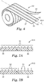
- FIG. 4a A cross-sectional side view of at least a portion of the resulting extruded article is shown in FIG. 4a .
- the longitudinal stripes 66, 68 will each have a cross-sectional shape in a plane perpendicular to the longitudinal direction with substantially parallel side edges 65 and 67.
- the joining surface 58 of an extrusion channels 50 slopes at an angle (e.g., an acute angle) toward the dispensing edge, the resulting different flow path lengths in the extrusion channel would typically lead to triangular shaped zones in the extrudate.
- the exit openings 62 of the first channels 50 can be desirable for the exit openings 62 of the first channels 50 to extend from the first side 32 of the distribution plate 26 toward but not all the way to the second side 34 of the distribution plate 26, for the exit openings 62' of the second channels 52 to extend from the second side 34 of the distribution plate 26 toward but not all the way to the first side 32 of the distribution plate 26, or both.
- the degree to which the exit openings 62, 62' of the first and second channels 50, 52 overlap each other can be varied (e.g., the first and second exit openings can have no overlap, can have some overlap or completely overlap), as desired.
- the exit openings 62 of the first channels 50 can extend from the first side 32 to the second side 34 of the distribution plate 26 (i.e., across the entire thickness of the distribution plate 26), the exit openings 62' of the second channels 52 can extend from the second side 34 to the first side 32 of the distribution plate 26 (i.e., across the entire thickness of the distribution plate 26), or both.
- a combination can also be used.
- a pair of first and second extrusion channels 50, 52 can have unequal widths. In some embodiments, a pair of first and second extrusion channels 50, 52 can have unequal depths. In some embodiments, a pair of first and second extrusion channels 50, 52 can have both unequal widths and unequal depths.
- the first extrusion channel exit opening 62 has at least one of a width that is at least ten (in some embodiments, at least 20, 30, 40, 50, 60, 70, 80, 90, 100, 200, 300, 400, or 500) percent larger than the width of at least one of the two adjacent second extrusion channel exit openings 62' or a depth that is at least ten (in some embodiments, at least 20, 30, 40, 50, 60, 70, 80, 90, 100, or 200) percent larger than the depth of at least one of the two adjacent second extrusion channel exit openings 62'.
- the width and depth of the first and second extrusion channels 50, 52 can be adjusted, for example, to accommodate the properties of the extruded polymer (e.g., viscosity, shear sensitivity, and flow resistance, which can increase as the reciprocal of the third power of the channel width) and to achieve the desired width of the longitudinal stripes in an extruded article.
- properties of the extruded polymer e.g., viscosity, shear sensitivity, and flow resistance, which can increase as the reciprocal of the third power of the channel width
- the width of the exit openings 62, 62' of the first and second extrusion channels 50, 52 can be adjusted as desired for a given application.
- the width of the second extrusion channel 52 exit openings 62' is greater than 1.5 mm (in some embodiments, at least 2, 3, 4, 5, or 6 mm), for example, in a range from 1.5 mm to 15 mm, 1.5 mm to 12 mm, or 2 mm to 10 mm.
- the width of the first extrusion channel 52 exit openings 62 is larger than the second extrusion channel exit openings (e.g., at least 10 percent larger as described above) and can be at least 5, 6, 7, 8, 9 or 10 mm, for example, in a range from 10 mm to 25 mm, 15 mm to 25 mm, or 15 mm to 20 mm.
- the maximum width of the exit openings 62, 62' of the first and second extrusion channels 50, 52 is generally determined by the fabricating machinery width limitations and can be, for example, at least 75, 80, 90, or 100 cm. Widths can be adjusted to allow for fabrication of extruded polymeric films for a wide variety of potential uses.
- the depth of the exit openings 62, 62' of the first and second extrusion channels 50, 52 can be adjusted as desired for a given application and may only be limited by the thickness of the distribution plate.
- the distribution plate is at least 5, 6, 7, 8, 9, or 10 mm thick.
- the distribution plate has a thickness of up to 20, 25, or 30 mm.
- the depth of the second extrusion channel 52 exit openings 62' is at least 0.25 mm (in some embodiments, at least 0.5, 1, 2, 3, 4, or 5 mm).
- the depth of the first extrusion channel 52 exit openings 62 can be larger than the second extrusion channel exit openings (e.g., at least 10 percent larger as described above) and can be at least 1, 2, 3, 4, 5, 6, 7, 8, 9 or 10 mm.
- both the first extrusion channels 50 and the second extrusion channels 52 have side walls 54 and 56 and a rear wall 55 that are substantially perpendicular to the corresponding side of the distribution plate 26 from which they are cut.
- the extrusion channels can be said to be box-shaped.
- the first extrusion channels 50 and the second extrusion channels 52 have unequal widths (i.e., their corresponding side walls are not spaced apart the same distance).
- the exit openings 62 of the first extrusion channels 50 extend from the first side 32 of the distribution plate 26 to a middle portion of the distribution plate 26 between the first side 32 and the second side 34, and the exit openings 62' of the second extrusion channels 52 extend from the second side 34 of the distribution plate 26 to the middle portion such that the exit openings 62 of the first extrusion channels 50 and the exit openings 62' of the second extrusion channels 52 do not overlap.
- the distribution plate 26 is typically compressed so as to form a tight seal in a region adjacent to the dispensing edge 36 between both first die portion 22 and second die portion 24. These seals keep the flowing polymeric material in cavities 38 and 40 entirely separate until they are dispensed from the dispensing edge 36.
- the distance along distribution plate 26 where the first and second die portions 22 and 24 seal against distribution plate 26 needs to be long enough to provide a robust seal and structural strength.
- the first polymeric material in the first cavity 38 can only reach dispensing edge 36 by entering the openings 60 of first grooves 50 in the direction from the first cavity 38 to the dispensing edge 36
- the second polymeric material in the second cavity 40 can only reach dispensing edge 36 by entering the openings (not labeled) of first grooves 52 in the direction from the second cavity 40 to the dispensing edge 36.
- the sealing of the first and second die portions and the distribution is aided by the use of adhesives and/or gaskets.
- the cross-sectional shape of the distribution plate 26 when viewed from the dispensing edge 36 is generally rectangular, which is advantageous for forming a tight seal between the first die portion 22 and the second die portion 24.
- the distribution plate does not have a cross-sectional shape that is pentagonal.
- the cross-sectional shape of the distribution plate in a plane perpendicular to the dispensing edge is also rectangular; in other embodiments, this cross-section is generally wedge-shaped to provide the distribution plate with more stiffness in the region near the dispensing edge.
- some of the entrance openings 60 of the first extrusion channels 50 comprise reinforcing members 59 extending from the distribution plate 26 along the entrance openings 60 toward the dispensing edge 36.
- at least some of the entrance openings 60 of the first extrusion channels 50 comprise reinforcing members 59.
- all of the entrance openings 60 of the first extrusion channels 50 comprise reinforcing members 59.
- the entrance openings of the second extrusion channels 52 do not comprise reinforcing members 59.
- reinforcing member 59 extends across the joining surface 58 and tapers in the direction of dispensing edge 36.
- the reinforcing member 59 in the illustrated embodiment divides channel 50 such that the first extrusion channel entrance openings 60 are separated into two sub-channels, but the tapering of the reinforcing member 59 may allow for combining a flow stream at the first extrusion channel exit openings 62.
- the reinforcing member 59 may extend all the way across the joining surface 58 to the dispensing edge 36 as shown in FIG. 4 , or the reinforcing member 59 may extend only part of the way across the joining surface 58.
- Reinforcing members formed in the distribution plate 26 may be useful, for example, for structural reinforcement of channels having widths of at least 15 mm to reduce deflection of the distribution plate 26 and prevent polymeric compositions on one side 34 of the distribution plate 26 from crossing over into lanes on the other side 32 of the distribution plate 26.
- reinforcing members 59 in the form of ribs extending across the entrance openings 60, other types of reinforcing members (e.g., joists, rafters, and posts) are envisioned.
- the die and method according to the present disclosure are useful for extruding two different polymeric compositions.
- the phrase "different polymeric compositions" and the phrase “second polymeric composition different from the first polymeric composition” refers to having at least one difference.
- the different polymeric compositions could be made of different polymers or a different blend of the same polymers or could have different additives (e.g., colorants, plasticizers, compatibilizer, or gas) in the same polymer or polymer blend.
- any two polymeric compositions that can be made to flow through the first and second extrusion channels 50, 52 may be used.
- the mass flow (or volume flow) of the two different polymeric compositions, as they are respectively extruded through the first and second extrusion channels 50, 52 can be equal or unequal.
- the two polymeric compositions may adhere to each other with a strong cohesive or adhesive bond, or be readily separable from each other (i.e., the bond between the first and second zones may be relatively easy to break).
- a polymeric composition can be selected for its surface properties or its bulk properties (e.g., tensile strength, elasticity, color, etc).
- a polymeric composition can be selected to provide specific functional or aesthetic properties in the extruded article such as elasticity, softness, hardness, stiffness, bendability, roughness, colors, textures, or patterns.
- the polymeric compositions that may be extruded in the die disclosed herein are thermoplastic polymeric compositions (e.g., polyolefins (e.g., polypropylene and polyethylene), polyvinyl chloride, polystyrenes and polystyrene block copolymers, nylons, polyesters (e.g., polyethylene terephthalate), polyurethanes, and copolymers and blends thereof).
- the die according to the present disclosure may also be useful for co-extruding polymeric materials that can be crosslinked (e.g., by heat or radiation).
- the die 20 can be heated to start the cure so as to adjust the viscosity of the polymeric material and/or the pressure in the corresponding die cavity 38 and 40.
- Co-extruding two different polymeric compositions may be useful, for example, for providing extruded articles having stripes with different tactile properties.
- One stripe may be softer to the touch than an adjacent stripe.
- Such extruded can be useful, for example, for providing hook fastener strips comprising soft edges.
- a second longitudinal stripe can be made softer than an adjacent first longitudinal stripe, for example, by using a second polymeric composition that is more elastomeric than the first polymeric composition or by using a second polymeric composition that is foamed.
- At least one of the two different polymeric compositions is foamed.
- the second polymeric composition is foamed.
- the second polymeric composition may have the same composition as the first polymeric composition, except for the presence of gas in the composition, or the second polymeric composition may be made from a different polymer or different polymer blend from the first polymeric composition.
- Foamed polymeric compositions can be prepared, for example, using a chemical foaming agent (e.g., a foaming agent available from Clariant Corp., Holden, Mass., under the trade designation "HYDROCEROL”) or by injecting a gas (e.g., carbon dioxide or nitrogen) into the polymeric composition.
- a chemical foaming agent e.g., a foaming agent available from Clariant Corp., Holden, Mass., under the trade designation "HYDROCEROL”
- a gas e.g., carbon dioxide or nitrogen
- a first polymeric composition comprising an inelastic polymer and a second polymeric composition comprising an elastomeric polymer are extruded.
- the term "inelastic” refers to polymers from which films (0.002 to 0.5 mm thick) can be made that have little or no recovery from stretching or deformation.
- the first polymeric composition can be formed, for example, of semicrystalline or amorphous polymers or blends.
- Inelastic polymers can be polyolefinic, formed predominantly of polymers such as polyethylene, polypropylene, polybutylene, or polyethylene-polypropylene copolymers.
- the first polymeric composition comprises polypropylene, polyethylene, polypropylene-polyethylene copolymer, or blends thereof.
- elastomeric refers to polymers from which films (0.002 to 0.5 mm thick) can be made that exhibit recovery from stretching or deformation.
- exemplary elastomeric polymeric compositions which can be used in the segmented multicomponent polymeric films disclosed herein include thermoplastic elastomers such as ABA block copolymers, polyurethane elastomers, polyolefin elastomers (e.g., metallocene polyolefin elastomers), polyamide elastomers, ethylene vinyl acetate elastomers, and polyester elastomers.
- An ABA block copolymer elastomer generally is one where the A blocks are polystyrenic, and the B blocks are conjugated dienes (e.g., lower alkylene dienes).
- the A block is generally formed predominantly of substituted (e.g, alkylated) or unsubstituted styrenic moieties (e.g., polystyrene, poly(alphamethylstyrene), or poly(t-butylstyrene)), having an average molecular weight from about 4,000 to 50,000 grams per mole.
- the B block(s) is generally formed predominantly of conjugated dienes (e.g., isoprene, 1,3-butadiene, or ethylene-butylene monomers), which may be substituted or unsubstituted, and has an average molecular weight from about 5,000 to 500,000 grams per mole.
- the A and B blocks may be configured, for example, in linear, radial, or star configurations.
- An ABA block copolymer may contain multiple A and/or B blocks, which blocks may be made from the same or different monomers.
- a typical block copolymer is a linear ABA block copolymer, where the A blocks may be the same or different, or a block copolymer having more than three blocks, predominantly terminating with A blocks.
- Multi-block copolymers may contain, for example, a certain proportion of AB diblock copolymer, which tends to form a more tacky elastomeric film segment.
- Other elastomers can be blended with block copolymer elastomers provided that the elastomeric properties are not adversely affected.
- Many types of thermoplastic elastomers are commercially available, including those from BASF under the trade designation "STYROFLEX”, from Shell Chemicals under the trade designation “KRATON”, from Dow Chemical under the trade designation “PELLETHANE” or “ENGAGE”, from DSM under the trade designation "ARNITEL”, from DuPont under the trade designation "HYTREL”, and more.
- thermoplastic elastomers including tetrablock styrene/ethylenepropylene/styrene/ethylene-propylene, described in U. S. Pat. No. 6,669,887 (Hilston et al. ) may also be useful.
- Elastomeric compositions may be selected, for example, for their compatibility or adhesion to inelastic compositions in an adjacent longitudinal stripe in the extruded article disclosed herein.
- First and second polymeric compositions which have good mutual adhesion properties may be selected.
- End block reinforcing resins and compatibilizers may also be used within second polymeric compositions.
- the second polymeric composition is a pressure sensitive adhesive. In some embodiments, the second polymeric composition is not a pressure sensitive adhesive.
- Pressure sensitive adhesives are well known to those of ordinary skill in the art to possess properties including the following: (1) aggressive and permanent tack, (2) adherence with no more than finger pressure, (3) sufficient ability to hold onto an adherend, and (4) sufficient cohesive strength to be cleanly removable from the adherend. In some applications (e.g., for hook fastener strips having soft edges), it is desirable for the second polymeric composition to not feel tacky to the touch.
- the second polymeric composition comprising an elastomeric polymer further comprises an inelastic polymer.
- the thermoplastic elastomer stripe is significantly thinner than the stripe of the inelastic polymer.
- the present inventors have found that including the inelastic polymer in the thermoplastic elastomer can be used to control the thickness of the second polymeric composition as it is extruded.
- the ratio of thermoplastic elastomer to inelastic polymer in the second polymeric composition may be in a range, for example, from 99.5:0.5 to 0.5:99.5, 99.5:0.5 to 10:90, 99.5:0.5 to 25:75, 99.5:0.5 to 50:50, 99:1 to 25:75, 95:5 to 25:75, 90:10 to 25:75, or 90:10 to 50:50.
- Controlling the ratio of thermoplastic elastomer to inelastic polymer in the second polymeric composition may also be useful, for example, for controlling the height of projections in embodiments of extruded articles provided with projections and for controlling the ability to slit or perforate the longitudinal stripe comprising the second polymeric composition, as described further below.
- the extruded article produced according to the present method can comprise a plurality of longitudinal first stripes of the first polymeric material alternating with a plurality of longitudinal second stripes of the second polymeric material.
- One first stripe is disposed between any two adjacent second stripes
- one second stripe is disposed between any two adjacent first stripes.
- at least one of the longitudinal first stripes and at least one of the longitudinal second stripes are integrally joined together.
- the joining of at least one of the longitudinal first stripes and at least one of the longitudinal second stripes can be accomplished on the land 43 in the cavity 42 between the dispensing edge 36 and the die lip 44 as shown in FIG. 2a .
- the longitudinal first stripes are generally parallel to one another
- the longitudinal second stripes are generally parallel to one another
- the longitudinal first and second stripes are generally parallel to each other.
- Each of the stripes can have a number of different cross sectional shapes.
- the co-extruded stripes prepared according to the method disclosed herein allow for alternating polymeric compositions arranged in the width direction (cross or x direction), which stripes extend along the length of the article or film (the y direction or machine direction).
- the polymeric composition of each stripe is generally consistent in the thickness direction (z direction) of the article (e.g., film). That is, although there may be some inhomogeneities in the first or second polymeric composition, in some embodiments, the stripes are not segmented in the z direction of the film.
- the method of making an extruded article according to the present disclosure comprises co-extruding a layer on at least one of the opposing major surfaces of the extruded article.
- Co-extruding refers to applying the layer within the die disclosed herein rather than in a post-extrusion step.
- the layer may have any desired thickness.
- the layer may be considered a skin layer, which may have a thickness, for example, that is up to 10, 8, 6, 5, 4, 3, or 2 percent of the thickness of the extruded article (e.g., film).
- the thickness of the stripe of the first or second polymeric composition may be at least 80, 85, 90, 95, or 96 percent of the thickness of the extruded article.
- the layer comprises a third polymeric composition that is different from both the first polymeric composition and the second polymeric composition.
- the term "different" used here refers to having at least one difference.
- the third polymeric composition could be made of a different polymer than the first and second polymeric compositions or a different blend of the same polymers.
- the third polymeric composition could have an additive (e.g., colorants, plasticizers, or compatibilizer) not found in the first or second polymeric composition or could lack an additive (e.g., colorants, plasticizers, or compatibilizer) that is present in one of the first or second polymeric compositions.
- a cross-sectional view of a portion of an exemplary extruded article 64b is shown in FIG. 5b , where longitudinal stripes 68, 66 composed of the first and second polymeric compositions, respectively, have co-extruded layers 70.
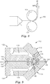
- FIG. 5 illustrates a cross-sectional side view of the die according to and/or useful for practicing the present disclosure, wherein the die has ports at the tip of the die or the back of the die for forming co-extruded layers.
- FIG. 5 shows ports 74 at the lip of the die and ports 72 at the back of the die, it should be understood that the die need not have both of these features in order to form co-extruded layers.
- each die portion 22 and 24 has a port 74 near the die lip into which a third polymeric composition could be fed.
- the ports 74 are between the die lip 44 and the dispensing edge 36 of the distribution plate 26.
- the third polymeric composition could be fed into at least one of the ports 74 and exit the corresponding slit 76 to form a co-extruded layer on at least one of the opposing major surfaces of the extruded article.
- the ports 74 could be introduced into the die portions 22, 24 by drilling or other suitable methods.
- the ports 74 may be useful for forming co-extruded layers on a relatively narrow die (e.g., up to about 25 cm wide).
- layers 70 on the opposing faces of extruded article 64 may be the same or different.
- Also shown in FIG. 5 are ports 72 at the back of the die.
- the ports 72 are in the form of annular rings around the inlets 28 and 30.
- the annular rings can be substantially round or oval.
- the third polymeric composition can surround the first and second polymeric compositions as they are extruded into their respective die cavities 38, 40 and through their respective extrusion channels 50, 52 on the distribution plate.
- Co-extruded layers can also be formed in a method according to the present disclosure using a multiple manifold die 110 as illustrated in FIG. 9 .
- manifold 175 is positioned next to die portion 124
- manifold 173 is position next to die portion 122.
- the first side 132 of the distribution plate 126 and the first die portion 122 together define a first die cavity 138
- the second side 134 of the distribution plate 126 and the second die portion 124 together define a second die cavity 140.
- inlets may be used to introduce first and second polymeric compositions into first and second die cavities 138 and 140, respectively, using inlets as shown in Figs. 2 and 5 .
- Inlets 178 can be used to introduce a third polymer composition or third and fourth polymeric compositions to manifolds 175 and 173.
- the third polymeric composition or third and fourth polymeric compositions are extruded through channels 176 to provide layers on the top and the bottom surfaces of the extrudate exiting the dispensing edge 136 of distribution plate 126.
- the manifolds 173 and 175 may be at an angle (e.g., about a 20 to 50 or a 30 degree angle) to the distribution plate 126.
- Heating elements 125 can be positioned in each die portion 122 and 124 and in manifolds 173 and 175.
- an extruded article having co-extruded top and bottom layers is formed after the extrudate reaches land 143 and is extruded out of die lip 144.
- the third and fourth polymeric compositions may be different from each other and each may be different from the first and second polymeric compositions. Therefore, the die and method according to the present disclosure may be useful for forming extruded article 64b where the longitudinal first and second stripes 66 and 68 and the two co-extruded layers 70 illustrated in FIG. 5b are each made from different polymeric compositions.
- FIG. 9 illustrates a three-manifold die 110 with a center manifold divided by distribution plate 126 to define cavities 138 and 140
- FIG. 9 illustrates a three-manifold die 110 with a center manifold divided by distribution plate 126 to define cavities 138 and 140
- Other configurations may be useful for providing co-extruded layers downstream of the distribution plate 126.
- Some useful configurations include additional manifolds for providing multiple co-extruded layers (e.g., more than one layer on each opposing surface) on the extruded article.
- the method and/or die according to the present disclosure can be useful for forming extruded articles that are segmented in the thickness direction.
- two or more dies according to the present disclosure can be used in combination to provide a multi-layer article.
- Each layer may have a different arrangement of at least two different polymeric compositions in segments that alternate along the film's cross direction and extend longitudinally.
- the die may dispense the flow stream into free space, or in some embodiments, the flow stream may be taken up onto a roller, web, or substrate.
- various secondary operations may then be performed on the article. Examples of such secondary operations may include embossing, laminating, slitting, knurling, and length and/or width stretching.
- the extruded article can comprise opposite major surfaces, and the method can further comprise providing projections on at least one of the major surfaces (e.g., by microreplicating or otherwise replicating a pattern in one or both of the major surfaces of the extruded article).
- Providing such projections can comprise contacting one or both of the major surfaces of the extruded article with a patterned roll, patterned belt, patterned film, or a combination thereof.
- the method can also comprise quenching or heating the extruded article respectively on a chilled or heated surface of, for example, a roller, web, flat or curved plate, or substrate.
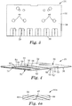
- FIG. 6 illustrates an extruded article made using the method according to the present invention, the extruded article being a film in the form of a roll.
- the extruded article 80 comprises an even number (4 as shown) of first longitudinal stripes 88 and an odd number (5 as shown) of second longitudinal stripes 86. Different numbers of stripes may also be useful; for example, 2 or 6 first longitudinal stripes 88 can alternate with 3 or 7, respectively, second longitudinal stripes 86.
- the second longitudinal stripes 86 are typically located at the first and second lateral edges 87, 89 and along the midline 80m of the film. In the illustrated embodiment, each of the second longitudinal stripes not located at the first or second lateral edge has a line of weakness 85 along its length.
- the line of weakness may be in the form of, for example, a series of perforations or slits.
- the line of weakness may also be a reduction in the thickness along a portion of the second longitudinal stripe. For example, thickness may be reduced by forming a grove in the second longitudinal stripe.
- the length and spacing of the perforations may be selected to provide a stable roll that can be unwound reliably when desired.
- the length of the perforations may be less than 15 (in some embodiments, up to 14, 13, 12, 11, or 10) mm.
- the composition of the second polymeric composition can be adjusted so that the longitudinal second stripes can be reliably perforated.
- the present inventors have found that longitudinal second stripes formed from a material that is too soft are difficult to reliably perforate and that it is advantageous to include an inelastic polymer with the elastomeric polymer in the second polymeric composition (see above).
- the film comprises opposing major surfaces, and at least one of the opposing major surfaces is provided with projections.
- Extruded article 80 may be useful, for example, in the manufacture of fastening tabs (e.g., for disposable absorbent articles such as pant-style diapers, open-style diapers, and incontinence garments).
- the roll can be unwound while the longitudinal stripes 88, 86 are separated along the lines of weakness 85 in the second longitudinal stripes 86 to provide an individual first longitudinal stripe 89 that has a second longitudinal stripe 86 along each of its lateral edges.
- the so-formed stripe can be cut in the cross-direction to provide an individual fastening tab that has a central region comprising the inelastic first polymeric composition and edges comprising the second polymeric composition comprising an elastomeric polymer.
- a fastening tab with edges comprising an elastomeric polymer may be softer to the touch and less irritating to the skin when applying or wearing a disposable absorbent article.
- the projections can be made on at least one or more of the longitudinal first stripes, on at least one or more of the longitudinal second stripes, or both. In some embodiments, projections are provided on both the longitudinal first stripes and the longitudinal second stripes.
- the projections provided on at least some of the longitudinal stripes can be formed using methods known in the art. For example, an extruded article, upon exiting the die disclosed herein, can be fed onto a continuously moving mold surface with cavities having the inverse shape of the projections. The cavities may be in the shape of projection having a loop-engaging head or may be in the shape of a precursor to a hook element (e.g., a partially formed hook element).
- the projections are formed as schematically shown in FIG. 8 .
- Extruded article 90 after leaving the die 1 is passed between a nip formed by two rolls 101, 103.
- the extruded article could be nipped, for example, between a die face and roll surface.
- At least one of the rolls 103 has cavities (not shown) in the inverse form of projections. Pressure provided by the nip forces the resin into the cavities.
- a vacuum can be used to evacuate the cavities for easier filling of the cavities.
- the nip is sufficiently wide such that a coherent film backing 90 is also formed over the cavities.
- the mold surface and cavities can be air or water cooled (e.g., by air or water) before stripping the integrally formed backing and upstanding formed stems from the mold surface such as by a stripper roll.
- This provides an extruded film 90 having integrally formed upstanding stems or hooks 84.
- the extruded article that is provided with projections has at least one co-extruded layer.
- a co-extruded skin layer of an inelastic material may be useful for facilitating the stripping of the formed stems from the mold surface.
- the projections formed upon exiting the cavities described above in connection with FIG. 8 do not have loop-engaging heads, the projections formed could be subsequently formed into hooks by a capping method as described in U.S. Pat. No. 5,077,870 (Melbye et al. ).
- the capping method includes deforming the tip portions of projections 84 using heat and/or pressure. The heat and pressure, if both are used, could be applied sequentially or simultaneously.
- the ribs of the thermoplastic web layer are then transversely cut or slit at spaced locations along the extension of the rib to form discrete portions of the rib having lengths in the direction of the rib essentially corresponding to the length of the projections to be formed.
- Extruded articles made using the method according to the present invention may comprise projections on at least one of the first longitudinal stripes or the second longitudinal stripes and on at least one of the opposing major surfaces of the film.
- the extruded article may be useful in a hook-and-loop fastening system, for example, as a hook strip.
- the projections e.g., hooks, stems, or ribs
- the longitudinal first stripe are provided with projections.
- the longitudinal second stripes are free of projections.
- FIG. 7A illustrates an exemplary extruded article 81A (e.g., an extruded film) where longitudinal first and second stripes 88, 86 are each provided with projections having loop-engaging heads 82.
- FIG. 7B illustrates an exemplary extruded article 81B (e.g., an extruded film) where projections on the longitudinal first stripes 88 comprise loop-engaging heads 82, and where projections on the longitudinal second stripes 86 comprise stems without loop-engaging heads 84.
- projections 82 and 84 have substantially the same height, which may be useful, for example, for uniform handling of an extruded article disclosed herein in the form of a web or a roll.
- Having projections with the substantially the same height in the longitudinal first and second stripes may also be desirable, for example, for appearance or feel.
- the height of the projections can be controlled by controlling the film height by adjusting, for example, the composition of the second polymeric composition as described above. If a capping process is used to form loop-engaging heads on projections on both the longitudinal first and second stripes, the composition of the second polymeric composition can be adjusted, for example, to make the heights of the projections on the longitudinal first and second stripes substantially the same before the capping process.
- the composition of the second polymeric composition can be adjusted, for example, to make the heights of the projections on the longitudinal second stripes shorter than the projections on the longitudinal first stripes so that after the capping process, the heights of the projections on the longitudinal first and second stripes is substantially the same.
- the method and die described herein can be used to make a variety of films or filmlike articles as well as other co-extruded articles (e.g., privacy film, light film, or co-extruded tubing).
- co-extruded articles e.g., privacy film, light film, or co-extruded tubing.
- a coextrusion die was assembled generally as depicted in FIG. 1 .
- the first die portion 22 and a second die portion 24 were fabricated from 17-4 stainless steel generally as depicted in FIG. 2 .
- a distribution plate 26 was prepared from 40 mils (1 mm) thick precision ground stainless steel sheet, generally as depicted in FIGS. 3 and 4 .
- the distribution plate 26 was prepared from 80 mils (2 mm) thick precision ground stainless steel.
- the distribution plate 26 was machined to provide a first and a second plurality of extrusion channels 50 and 52, generally as depicted in FIG. 4 .
- extrusion channels 50 and 52 were cut into the dispensing edge 36 of the distribution plate 26.
- the dimensions of the channels are shown in Tables 1 and 3, below, with the depth referring to the thickness of the dispensing edge.
- the extrusion channels 50 and 52 were 28 mm in length (from the dispensing edge 36 to the rear wall 55).
- the entrance openings of extrusion channels 50 were formed with reinforcing ribs 59 that extended 24 mm from the rear wall 55 toward the dispensing edge 36.
- extrusion channels were prepared with a repeat across the dispensing edge in an alternating pattern at a spacing of the width of the Polymer A channels plus the width of the Polymer B channels, as given in Tables 1 and 3, below.
- the full width of die lip 44 was 8 inches (20 cm).
- the first material inlet (introducing Polymer A from Table 1 below into the extrusion die) was fed with a melt train focused around a 40 mm twin screw extruder.
- the second material inlet (introducing Polymer B from Tables 1 below into the extrusion die) was fed with a melt train focused around a 50 mm single screw extruder.
- the extrusion barrel temperatures used ranged from 100-230 °C, with the lowest temperatures corresponding to the inlet section.
- the metering section of the extruder was maintained at 230 °C.
- the die temperature was 230 °C for both manifold sides. Total mass output from the process ranged from 15 to 20 kg/hr.
- Example 1 was run at a 5 kg/hr mass output and at slower line speed. During the co-extrusion runs, the die was positioned adjacent to a chilled roller so that the coextruded film was quenched while being taken away on the chilled roller. Down web, the coextruded film was wound up into a roll.
- the mass ratio of major channel Polymer A to minor channel Polymer B was varied to achieve the targeted parallel lane dimensions.
- the major channel Polymer A was a film grade polypropylene (PP) copolymer, a polypropylene impact copolymer obtained from Dow Chemical Co., Midland, MI, under the trade designation "DOW C700-35N POLYPROPYLENE" that was pigmented blue.
- PP polypropylene
- the minor channel Polymer B was a polyolefin thermoplastic elastomer or polyolefin thermoplastic elastomer and polyolefin blend.
- TPE is an ethylene-octene copolymer obtained from Dow Chemical Co. under the trade designation "ENGAGE 8200 POLYOLEFIN ELASTOMER”
- LDPE is a low density polyethylene obtained from ExxonMobil Chemical Co., Houston, TX, under the trade designation "EXXON MOBIL LD 123.LN”. Materials and extrusion temperatures and conditions for Examples 1 to 4 were as shown in Table 1, below.
- Example 1 Example 2
- Examples 1 to 4 resulted in coextruded films with alternating stripes of pigmented Polymer A and stripes of clear Polymer B in the cross direction of the film. Lane width dimensions and film basis weights are provided in Table 2, below. Table 2 Example Film Basis Weight (g/m 2 ) Polymer A Lane Width (mm) Polymer B Lane Width (mm) Example 1 124 20 9 Example 2 100 20 2 Example 3 110 18 4 Example 4 94 13 4
- Examples 5-8 were prepared as described above for Examples 1-4 with the following modifications.
- the lane backing thicknesses were changed by varying the ratio of TPE and PP and holding the other process conditions constant. Materials and extrusion temperatures and conditions for Examples 5-8 were as shown in Table 3, below.
- Example 5 Example 6
- Examples 5-8 resulted in coextruded films with alternating stripes of pigmented Polymer A and stripes of clear Polymer B in the cross direction of the film.
- the lane thickness dimensions are provided shown in Table 4.
- the Polymer A lane width was 13 mm, and the Polymer B lane width was 4 mm for each of Examples 5-8.
- Table 4 Example Polymer A Lane Film Thickness ( ⁇ m) Polymer B Lane Film Thickness ( ⁇ m) Example 5 130 100 Example 6 120 100 Example 7 125 135 Example 8 115 180
- Examples 9 and 10 were prepared as described above for Examples 2 and 4, except that projections were provided on one surface of the extruded film article.
- the projections were formed as shown and described for FIG. 8 .
- the extruded film article upon exiting the die, was passed between a nip formed by two rolls, with one of the rolls having cavities in the shape of the projections.
- This provided a segmented multicomponent polymer film having integrally formed upstanding stems on one surface.
- the stems were subsequently formed into hooks by a capping method, as described in U.S. Pat. No. 5,077,870 (Melbye et al. ), col. 5, lines 50-60.
- Examples 9 to 10 were each formed with a 1600 hooks per square inch array with a total height of 360 ⁇ m, a backing film thickness of 100 ⁇ m, and with hook head of 300 - 330 ⁇ m diameter.
Description
- Co-extrusion of multiple polymeric components into a single layer film is known in the art. For example, multiple polymeric flow streams have been combined in a die or feedblock in a layered fashion to provide a top to bottom multilayer film. It is also known to provide more complicated co-extruded film structures where the film is partitioned, not as coextensive layers in the thickness direction, but as stripes along the width dimension of the film. This has sometimes been called "side-by-side" co-extrusion. Extruded products with side-by-side oriented stripes are described, for example, in
U. S. Pat. Nos. 4,435,141 (Weisner et al. ),6,159,544 (Liu et al. ),6,669,887 (Hilston et al. ), and7,678,316 (Ausen et al. ). - Even though extrusion devices are known for producing extruded products with side-by-side oriented extruded stripes, there is still a need for alternatives and improvements to such devices.
-
US 6,159,544 relates to a die set and method for the production of multiple stripes with two different materials A and B adjacent to each other. The special feature of this method is that a specially designed shim is inserted between two pieces of coating dies. When liquids A and B enter the two sides of the die set separately, B liquid will flow through the distribution passages in the shim to form multiple stripes and then contact stripes of A liquid in the same slot section. - A die and method as defined by the independent claims are provided. Further preferred embodiments of the invention are defined in the dependent claims.
- In one aspect, the present disclosure provides a die according to claim 1 for co-extruding at least a first extrudable polymeric composition and a second extrudable polymeric composition. The die comprises a first die cavity in a first die portion, a second die cavity in a second die portion, a distribution plate interposed between at least a portion (e.g., most or all) of the first die cavity and at least a portion (e.g., most or all) of the second die cavity. The distribution plate has a first side forming a boundary of the first die cavity, a second side forming a boundary of the second die cavity, a dispensing edge, a plurality of first extrusion channels, and a plurality of second extrusion channels. The first extrusion channels extend from entrance openings at the first die cavity to exit openings on the dispensing edge, and the second extrusion channels extend from entrance openings at the second die cavity to exit openings on the dispensing edge. The exit openings of the first extrusion channels and the exit openings of the second extrusion channels are disposed in alternating positions along the dispensing edge. Each of the first extrusion channels comprises two opposite side walls and a joining surface connecting the two opposite side walls, and wherein the joining surface of at least some of the first extrusion channels is substantially parallel to the first side of the distribution plate, wherein each of the first extrusion channels further comprises a rear wall opposite the exit opening and connecting the two opposite side walls, the rear wall being substantially perpendicular to the first side of the distribution plate.
- In another aspect, the present disclosure provides a method according to claim 9 of making an extruded article, the method comprising providing the die described above, supplying a first polymeric composition into the first die cavity; supplying a second polymeric composition, different from the first polymeric composition, into the second die cavity; extruding the first polymeric composition through the plurality of first extrusion channels and the second polymeric composition through the plurality of second extrusion channels so as to form a flow stream having a width with alternating zones of the first and second polymeric compositions, and extruding the flow stream out of the die in a longitudinal direction so as to form the extruded article, the extruded article comprising a plurality of longitudinal first stripes of the first polymeric composition alternating with a plurality of longitudinal second stripes of the second polymeric composition, wherein at least some of the longitudinal first stripes have, in a plane perpendicular to the longitudinal direction, a cross-sectional shape comprising substantially parallel opposite sides.
- In the die and the method according to the present disclosure, management of the flow of different polymer compositions into side-by-side lanes advantageously can be carried out using a single manifold die with a distribution plate in contrast to approaches that require multiple dies to achieve side-by-side co-extrusion. Also, in some embodiments, the die is readily modified to provide additional polymeric layers over the side-by-side lanes, which layers may be the same or different from the polymers in the side-by-side lanes. The distribution plate can be used at a die lip with a short distance between the die lip and the dispensing edge, which allows for a high level of control of the polymer lanes. The distribution plate can be relatively inexpensive to machine to meet desired requirements for thickness, lane widths, and land length and to accommodate changes in pressure and polymer melt characteristics. The use of the distribution plate disclosed herein can reduce or eliminate the need for expensive machining of the primary die halves. Also, the distribution plate having first and second sides has a geometry that allows it to readily seal against the first and second die portions. Thus, the distribution plate useful for practicing the present disclosure may provide significant cost and performance advantages over, for example, die bars with more complex geometries. Typically, the distribution plate may be understood to have two major sides, the first major side and the second major side, each connected to the dispensing edge and the opposing edge. In other words, the distribution plate may be understood to have only two sides, the first side and the second side, and only up to four edges.
- The method and die defined by the claims can be useful, for example, for preparing extruded articles with longitudinal stripes comprising different polymeric compositions. Accordingly, there is disclosed an extruded film having first and second lateral edges and a midline, the extruded film comprising an even number of longitudinal first stripes of a first polymeric composition comprising an inelastic polymer alternating with an odd number of longitudinal second stripes of a second polymeric composition comprising an elastomeric polymer such that the longitudinal second stripes are located at least at the first and second lateral edges and at the midline, wherein each of the longitudinal second stripes not located at the first and second lateral edges has a line of weakness along its length. Typically, at least some of the longitudinal first stripes have, in a plane perpendicular to the midline, a cross-sectional shape comprising substantially parallel opposite sides. In some embodiments, the extruded film comprises opposing major surfaces, and at least one of the major surfaces is provided with projections (e.g., with loop-engaging heads). Such films can be useful, for example, for providing hook strips comprising inelastic polymers having edges made from softer, elastomeric materials.
- When preparing extruded film having projections using the methods defined by the claims, it has now been found that it is possible to control the film height by controlling the composition of the second polymeric material. Accordingly, there is disclosed an extruded film comprising a plurality of longitudinal first stripes of a first polymeric composition comprising an inelastic polymer alternating with a plurality of longitudinal second stripes of a second polymeric composition comprising a blend of an elastomeric polymer and an inelastic polymer, wherein both the plurality of longitudinal first stripes and the plurality of longitudinal second stripes are provided with projections, the projections of the plurality of longitudinal first stripes being substantially the same height as the projections of the plurality of longitudinal second stripes. Typically, at least some of the longitudinal first stripes have, in a plane perpendicular to the longitudinal direction, a cross-sectional shape comprising substantially parallel opposite sides. "Substantially the same height" can mean, for example, that the heights of the projections of the second stripes can be within 10, 8, 5, 4, 3, 2, or 1 percent of the heights of the projections of the first stripes. Such films can be useful, for example, for providing hook strips comprising inelastic polymers having edges made from softer, elastomeric materials.
- In this application, terms such as "a", "an" and "the" are not intended to refer to only a singular entity, but include the general class of which a specific example may be used for illustration. The terms "a", "an", and "the" are used interchangeably with the term "at least one". The phrases "at least one of" and "comprises at least one of" followed by a list refers to any one of the items in the list and any combination of two or more items in the list. All numerical ranges are inclusive of their endpoints and non-integral values between the endpoints unless otherwise stated.
- The term "alternating" as used herein refers to one first extrusion channel or longitudinal stripe being disposed between any two adjacent second channels or stripes (i.e., second channels or stripes that only have one first channel or stripe between them) and one second channel or stripe being disposed between any two adjacent first channels or stripes.
- The terms "first" and "second" are used in this disclosure. It will be understood that, unless otherwise noted, those terms are used in their relative sense only. In particular, in some embodiments certain components may be present in interchangeable and/or identical multiples (e.g., pairs). For these components, the designation of "first" and "second" may be applied to the components merely as a matter of convenience in the description of one or more of the embodiments.
- The term "die" will be understood to include a die through which materials (as described herein) may be forced, pressed, pushed, shaped or otherwise directed through the die to provide the described product (e.g., extruded article or extruded film).
- The term "loop-engaging" as used herein relates to the ability of a projection to be mechanically attached to a loop material. Generally, stem projections with loop-engaging heads have a head shape that is different from the shape of the stem. For example, the projection may be in the shape of a mushroom (e.g., with a circular or oval head enlarged with respect to the stem), a hook, a palm-tree, a nail, a T, or a J. The loop-engageability of projections may be determined and defined by using standard woven, nonwoven, or knit materials. A region of projections with loop-engaging heads generally will provide, in combination with a loop material, at least one of a higher peel strength, higher dynamic shear strength, or higher dynamic friction than a region of projections without loop-engaging heads. Typically, projections that have loop-engaging heads have a maximum thickness dimension of up to about 1 (in some embodiments, 0.9, 0.8, 0.7, 0.6, 0.5, or 0.45) millimeter.
- The term "substantially parallel" as used herein to refer to two surfaces of the distribution plate or to two sides of a cross-sectional shape means that the two parallel surfaces or sides deviate from parallel by up to 10 (in some embodiments, up to 7.5 or 5) degrees.
- The term "substantially perpendicular" as used herein to refer to the relationship between the side or rear walls of the extrusion channels and the first side of the distribution plate means that the wall and the first side deviate from perpendicular by up to 10 (in some embodiments, up to 7.5 or 5) degrees. However, substantially perpendicular side or rear walls can have a curvature at the joining surface to eliminate a dead spot in a corner of the extrusion channel.
- The disclosure may be more completely understood in consideration of the following detailed description of various embodiments of the disclosure in connection with the accompanying drawings, in which:
-
FIG. 1 is a perspective view of an extrusion die in accordance with one embodiment of the present disclosure; -
FIG. 2 is a cross-sectional side view of the extrusion die ofFIG. 1 , taken along section lines 2-2 inFIG. 1 ; -
FIG. 2a is an enlargement of a region marked 2a inFIG. 2 ; -
FIG. 3 is a top view of a distribution plate from the extrusion die ofFIGS. 1 and 2 , shown in isolation; -
FIG. 4 is a perspective view of a distribution plate from the extrusion die ofFIGS. 1 and 2 , shown in isolation; -
FIG. 4a is a cross-sectional side view of an embodiment of at least a portion of an extruded article preparable from a die and method according to the present disclosure; -
FIG. 5 is a cross-sectional side view of the extrusion die ofFIG. 1 , taken along section lines 2-2 inFIG. 1 , and having ports at the tip of the die or the back of the die for forming co-extruded layers; -
FIG. 5a is an enlargement of a region marked 5a inFIG. 5 ; -
FIG. 5b is a cross-sectional side view of at least a portion of an extruded article having co-extruded layers preparable using the extrusion die ofFIG. 5 ; -
FIG. 6 is a perspective view of an extruded article according to the present disclosure, the extruded article being in the form of a roll; -
FIG. 7A is a perspective cross-sectional view of an extruded article where each of the longitudinal stripes is provided with projections having loop-engaging heads; -
FIG. 7B is a perspective cross-sectional view of an extruded article where one of the longitudinal stripes is provided with projections having loop-engaging heads, and one of the longitudinal stripes is provided with projections without loop-engaging heads; -
FIG. 8 is a schematic view of an apparatus and method according to some embodiments, where at least one of the stripes of the extruded article is provided with projections; and -
FIG. 9 is a cross-sectional side view of an extrusion die according to another embodiment, which die can be useful for forming co-extruded layers. - In describing preferred embodiments of the invention, specific terminology is used for the sake of clarity.
- Referring now to
FIG. 1 , the illustrated embodiment of an extrusion die 20 in accordance with the present disclosure and useful for practicing the methods disclosed herein includes afirst die portion 22 and asecond die portion 24. Adistribution plate 26, typically in the form of a profiled metal shim, is disposed between the first and thesecond die portions first die portion 22 has afirst inlet 28 for receiving a supply of a first extrudable polymeric composition, and thesecond die portion 24 has asecond inlet 30 for receiving a supply of a second extrudable polymeric composition. In typical operation, thefirst inlet 28 and thesecond inlet 30 are connected to respective sources of extrudable polymeric compositions such as, for example, melt pipes or heated hoses of conventional type connected to pumps or screw extruders. In some embodiments, the materials may be supplied to the die using one or more extruders (e.g., single or twin screw). In other embodiments, the materials may be supplied to the die using, for example, a grid melter and a gear pump, or other sources of molten material (e.g., molten polymeric material). - Referring now to
FIGS. 2 and 2a , thedistribution plate 26 has afirst side 32 and asecond side 34 and a dispensingedge 36. Thedistribution plate 26 can be, for example, an integral or separate shim, membrane or other dividing partition disposed so as to separate the first and second diecavities first side 32 of thedistribution plate 26 and thefirst die portion 22 together define afirst die cavity 38, and thesecond side 34 of thedistribution plate 26 and thesecond die portion 24 together define asecond die cavity 40.Heating elements 25 can be positioned in each die portion. In the depicted exemplary embodiment, thedie portions cavity 42 formed in front of the dispensingedge 36 and recessed back inside the die 20 from adie lip 44 through which polymeric materials are extruded. The recessedcavity 42 includes aland 43. During use of the die 20, thecavities distribution plate 26 will be filled with pressurized extrudable polymeric material. Therefore, care should be taken so that the pressure differential between thesecavities distribution plate 26. In some embodiments, the distribution plate is at least 2.5, 3, 3.5, 4, 4.5, 5, 6, 7, 8, 9, or 10 millimeters (mm) thick. - In some embodiments, the die according to and/or useful for practicing the present disclosure comprises a die lip 44 (e.g., in the form of a slot or any desired shape) through which an extrudate comprising the first and second polymeric compositions can be extruded. As shown in
FIG. 2a , thedistribution plate 26 from the extrusion die 20 according to and/or useful for practicing the present disclosure can be designed and placed so that the dispensingedge 36 is recessed back from thedie lip 44 and thecavity 42 can be formed. Recessing the dispensingedge 36 and forming the recessedcavity 42 are useful in many embodiments, but it is not considered a requirement of the present disclosure. In some embodiments, the dispensing edge is within about 2.5 centimeters (cm) from the die lip. In some embodiments, the dispensing edge is within about 7.5, 6.25, 5, 3.75, 2.5, 1.9, 1.3, 0.635, or 0.5 cm from the die lip. For example, the dispensing edge may be in a range from about 0.5 to 7.5 cm, 0.5 to 2.5, or 0.635 to 2.5 cm from the die lip. The distance between the dispensing edge and the die lip should typically be long enough to establish the flow of the polymer extrudate, which typically requires that the distance over the height of the polymer is in a range from 1 to 10. If the distance between the dispensing edge and the die lip is too long, for example, longitudinal stripes at the edges of the polymer extrudate may become distorted. The walls of recessedcavity 42 can be straight (i.e., the die opening can be dimensionally comparable in height to the dispensing edge) or tapered toward the die lip 44 (i.e., the die opening can be smaller in height than the dispensing edge). It can also be desirable to have the recessed cavity taper in width, for example, after the flowstreams combine. - Referring now to
FIG. 3 , several throughholes 46 can be formed through thedistribution plate 26 for receiving therethrough a mechanism (e.g. machine bolts) for holding the various components of the extrusion die 20 together as an assembly. - In the embodiment of the distribution plate according to and/or useful for practicing the present disclosure shown in
FIG. 4 , the first andsecond extrusion channels distribution plate 26. Each of the channels can also be, for example, in the form of a tunnel or other pathway cut or otherwise formed in the distribution plate. Referring toFIG. 4 , a first plurality ofchannels 50 in the form of grooves have been cut into thefirst side 32 ofdistribution plate 26 such that in the assembled die 20 thechannels 50 extend from (i.e., connect) thefirst cavity 38 to the dispensingedge 36. Further, a second plurality ofchannels 52 in the form of grooves have been cut into thesecond side 34 ofdistribution plate 26 such that in the assembled die 20 thechannels 52 extend from (i.e., connect) thesecond cavity 40 to the dispensingedge 36. Each of thechannels opposite side walls rear wall 55 between theopposite side walls surface 58 that connects theside walls first channels 50 and a top ceiling in the case of the second channels 52), anentrance opening 60 on the corresponding side of thedistribution plate 26 and anexit opening 62, 62' on the dispensingedge 36 of thedistribution plate 26 opposite therear wall 55. As illustrated, thechannels edge 36 such that onefirst channel 50 is disposed between any two adjacentsecond channels 52. Similarly, onesecond channel 52 is disposed between any two adjacentfirst channels 50. - The
first extrusion channels 50 andsecond extrusion channels 52 can be formed in thedistribution plate 26 by a number of different methods (e.g., milling, plunge electrical discharge machining (EDM), acid etching, e-beam machining, or diamond machining). - The profiles of the first and
second channels opposite side walls opposite side walls side walls first channels 50 can be formed perpendicular or slanted at an angle (other than a right angle) to the first side of thedistribution plate 26, or theside walls first channels 50 can be formed so as to taper out from their joiningsurface 58 to thefirst side 32 and the dispensingedge 36 of the distribution plate 26 (i.e., the distance between the side walls adjacent the joining surface can be smaller than the distance between the side walls either adjacent the first side of the distribution plate, adjacent the dispensing edge, or both). Likewise, theside walls second channels 52 can be formed perpendicular or slanted at an angle (other than a right angle) to thesecond side 34 of thedistribution plate 26, or theside walls second channels 52 can be formed so as to taper out from their joiningsurface 58 to the second side and the dispensing edge of the distribution plate 26 (i.e., the distance between the side walls adjacent the joining surface can be smaller than the distance between the side walls either adjacent the second side of the distribution plate, adjacent the dispensing edge, or both). Theside walls channels distribution plate 26 and the dispensingedge 36, or one set of channels (e.g., 50) can be perpendicular and the other set (e.g, 52) tapered or slanted. The use of slanteddie channels - The joining
surface 58 of at least some (e.g., most or all) of thefirst extrusion channels 50 is substantially parallel to thefirst side 32 of thedistribution plate 26. In some embodiments, the joiningsurface 58 of at least some (e.g., most or all) of thesecond extrusion channels 52 is substantially parallel to thesecond side 34 of the distribution plate. In some embodiments, the joiningsurface 58 of at least some (e.g., most or all) of both thefirst extrusion channels 50 and the second extrusion channels are substantially parallel to the first and second substantially parallel sides of the distribution plate. A joiningsurface 58 that is substantially parallel to the first or second side of the distribution plate will typically form zones in the extrudate with substantially parallel side edges. A cross-sectional side view of at least a portion of the resulting extruded article is shown inFIG. 4a . In theextruded article 64a, thelongitudinal stripes surface 58 of anextrusion channels 50 slopes at an angle (e.g., an acute angle) toward the dispensing edge, the resulting different flow path lengths in the extrusion channel would typically lead to triangular shaped zones in the extrudate. - Depending on the desired configuration of the resulting extrudate, it can be desirable for the
exit openings 62 of thefirst channels 50 to extend from thefirst side 32 of thedistribution plate 26 toward but not all the way to thesecond side 34 of thedistribution plate 26, for the exit openings 62' of thesecond channels 52 to extend from thesecond side 34 of thedistribution plate 26 toward but not all the way to thefirst side 32 of thedistribution plate 26, or both. In this way, the degree to which theexit openings 62, 62' of the first andsecond channels exit openings 62 of thefirst channels 50 can extend from thefirst side 32 to thesecond side 34 of the distribution plate 26 (i.e., across the entire thickness of the distribution plate 26), the exit openings 62' of thesecond channels 52 can extend from thesecond side 34 to thefirst side 32 of the distribution plate 26 (i.e., across the entire thickness of the distribution plate 26), or both. A combination can also be used. - In some embodiments of the die according to and/or useful for practicing the present disclosure, a pair of first and
second extrusion channels second extrusion channels second extrusion channels channel exit opening 62 has at least one of a width that is at least ten (in some embodiments, at least 20, 30, 40, 50, 60, 70, 80, 90, 100, 200, 300, 400, or 500) percent larger than the width of at least one of the two adjacent second extrusion channel exit openings 62' or a depth that is at least ten (in some embodiments, at least 20, 30, 40, 50, 60, 70, 80, 90, 100, or 200) percent larger than the depth of at least one of the two adjacent second extrusion channel exit openings 62'. The width and depth of the first andsecond extrusion channels - The width of the
exit openings 62, 62' of the first andsecond extrusion channels second extrusion channel 52 exit openings 62' is greater than 1.5 mm (in some embodiments, at least 2, 3, 4, 5, or 6 mm), for example, in a range from 1.5 mm to 15 mm, 1.5 mm to 12 mm, or 2 mm to 10 mm. Typically the width of thefirst extrusion channel 52exit openings 62 is larger than the second extrusion channel exit openings (e.g., at least 10 percent larger as described above) and can be at least 5, 6, 7, 8, 9 or 10 mm, for example, in a range from 10 mm to 25 mm, 15 mm to 25 mm, or 15 mm to 20 mm. The maximum width of theexit openings 62, 62' of the first andsecond extrusion channels - The depth of the
exit openings 62, 62' of the first andsecond extrusion channels second extrusion channel 52 exit openings 62' is at least 0.25 mm (in some embodiments, at least 0.5, 1, 2, 3, 4, or 5 mm). The depth of thefirst extrusion channel 52exit openings 62 can be larger than the second extrusion channel exit openings (e.g., at least 10 percent larger as described above) and can be at least 1, 2, 3, 4, 5, 6, 7, 8, 9 or 10 mm. - In the embodiment of the
distribution plate 26 illustrated inFIG. 4 , both thefirst extrusion channels 50 and thesecond extrusion channels 52 haveside walls rear wall 55 that are substantially perpendicular to the corresponding side of thedistribution plate 26 from which they are cut. The extrusion channels can be said to be box-shaped. Thefirst extrusion channels 50 and thesecond extrusion channels 52 have unequal widths (i.e., their corresponding side walls are not spaced apart the same distance). Furthermore, in the illustrated embodiments, theexit openings 62 of thefirst extrusion channels 50 extend from thefirst side 32 of thedistribution plate 26 to a middle portion of thedistribution plate 26 between thefirst side 32 and thesecond side 34, and the exit openings 62' of thesecond extrusion channels 52 extend from thesecond side 34 of thedistribution plate 26 to the middle portion such that theexit openings 62 of thefirst extrusion channels 50 and the exit openings 62' of thesecond extrusion channels 52 do not overlap. - The
distribution plate 26 is typically compressed so as to form a tight seal in a region adjacent to the dispensingedge 36 between bothfirst die portion 22 andsecond die portion 24. These seals keep the flowing polymeric material incavities edge 36. The distance alongdistribution plate 26 where the first and second dieportions distribution plate 26 needs to be long enough to provide a robust seal and structural strength. The first polymeric material in thefirst cavity 38 can only reach dispensingedge 36 by entering theopenings 60 offirst grooves 50 in the direction from thefirst cavity 38 to the dispensingedge 36, and the second polymeric material in thesecond cavity 40 can only reach dispensingedge 36 by entering the openings (not labeled) offirst grooves 52 in the direction from thesecond cavity 40 to the dispensingedge 36. In some embodiments, the sealing of the first and second die portions and the distribution is aided by the use of adhesives and/or gaskets. - In some embodiments, the cross-sectional shape of the
distribution plate 26 when viewed from the dispensingedge 36 is generally rectangular, which is advantageous for forming a tight seal between thefirst die portion 22 and thesecond die portion 24. Thus the die according to and/or useful for practicing the present disclosure can have advantages over more complex dies that have three die portions that need to be sealed against a die bar at angles to each other. In some embodiments, the distribution plate does not have a cross-sectional shape that is pentagonal. In some embodiments, the cross-sectional shape of the distribution plate in a plane perpendicular to the dispensing edge is also rectangular; in other embodiments, this cross-section is generally wedge-shaped to provide the distribution plate with more stiffness in the region near the dispensing edge. - In the embodiment illustrated in
FIG. 4 , some of theentrance openings 60 of the first extrusion channels 50 (grooves as shown) comprise reinforcingmembers 59 extending from thedistribution plate 26 along theentrance openings 60 toward the dispensingedge 36. In some embodiments, at least some of theentrance openings 60 of thefirst extrusion channels 50 comprise reinforcingmembers 59. In some embodiments, all of theentrance openings 60 of thefirst extrusion channels 50 comprise reinforcingmembers 59. In some of these embodiments, the entrance openings of thesecond extrusion channels 52 do not comprise reinforcingmembers 59. As shownFIG. 4 , reinforcingmember 59 extends across the joiningsurface 58 and tapers in the direction of dispensingedge 36. The reinforcingmember 59 in the illustrated embodiment divideschannel 50 such that the first extrusionchannel entrance openings 60 are separated into two sub-channels, but the tapering of the reinforcingmember 59 may allow for combining a flow stream at the first extrusionchannel exit openings 62. The reinforcingmember 59 may extend all the way across the joiningsurface 58 to the dispensingedge 36 as shown inFIG. 4 , or the reinforcingmember 59 may extend only part of the way across the joiningsurface 58. Reinforcing members formed in thedistribution plate 26 may be useful, for example, for structural reinforcement of channels having widths of at least 15 mm to reduce deflection of thedistribution plate 26 and prevent polymeric compositions on oneside 34 of thedistribution plate 26 from crossing over into lanes on theother side 32 of thedistribution plate 26. Although the illustrated embodiment shows reinforcingmembers 59 in the form of ribs extending across theentrance openings 60, other types of reinforcing members (e.g., joists, rafters, and posts) are envisioned. - The die and method according to the present disclosure are useful for extruding two different polymeric compositions. The phrase "different polymeric compositions" and the phrase "second polymeric composition different from the first polymeric composition" refers to having at least one difference. For example, the different polymeric compositions could be made of different polymers or a different blend of the same polymers or could have different additives (e.g., colorants, plasticizers, compatibilizer, or gas) in the same polymer or polymer blend.
- Any two polymeric compositions that can be made to flow through the first and
second extrusion channels second extrusion channels - In some embodiments, the polymeric compositions that may be extruded in the die disclosed herein are thermoplastic polymeric compositions (e.g., polyolefins (e.g., polypropylene and polyethylene), polyvinyl chloride, polystyrenes and polystyrene block copolymers, nylons, polyesters (e.g., polyethylene terephthalate), polyurethanes, and copolymers and blends thereof). However, the die according to the present disclosure may also be useful for co-extruding polymeric materials that can be crosslinked (e.g., by heat or radiation). When a heat curable resin is used, the die 20 can be heated to start the cure so as to adjust the viscosity of the polymeric material and/or the pressure in the
corresponding die cavity - Co-extruding two different polymeric compositions may be useful, for example, for providing extruded articles having stripes with different tactile properties. One stripe may be softer to the touch than an adjacent stripe. Such extruded can be useful, for example, for providing hook fastener strips comprising soft edges. A second longitudinal stripe can be made softer than an adjacent first longitudinal stripe, for example, by using a second polymeric composition that is more elastomeric than the first polymeric composition or by using a second polymeric composition that is foamed.
- In some embodiments, at least one of the two different polymeric compositions is foamed. For example, in some embodiments, the second polymeric composition is foamed. In these embodiments, the second polymeric composition may have the same composition as the first polymeric composition, except for the presence of gas in the composition, or the second polymeric composition may be made from a different polymer or different polymer blend from the first polymeric composition. Foamed polymeric compositions can be prepared, for example, using a chemical foaming agent (e.g., a foaming agent available from Clariant Corp., Holden, Mass., under the trade designation "HYDROCEROL") or by injecting a gas (e.g., carbon dioxide or nitrogen) into the polymeric composition.
- In some embodiments of the method of making an extruded article and the extruded articles according to the present disclosure, a first polymeric composition comprising an inelastic polymer and a second polymeric composition comprising an elastomeric polymer are extruded. The term "inelastic" refers to polymers from which films (0.002 to 0.5 mm thick) can be made that have little or no recovery from stretching or deformation. The first polymeric composition can be formed, for example, of semicrystalline or amorphous polymers or blends. Inelastic polymers can be polyolefinic, formed predominantly of polymers such as polyethylene, polypropylene, polybutylene, or polyethylene-polypropylene copolymers. In some embodiments, the first polymeric composition comprises polypropylene, polyethylene, polypropylene-polyethylene copolymer, or blends thereof.
- The term "elastomeric" refers to polymers from which films (0.002 to 0.5 mm thick) can be made that exhibit recovery from stretching or deformation. Exemplary elastomeric polymeric compositions which can be used in the segmented multicomponent polymeric films disclosed herein include thermoplastic elastomers such as ABA block copolymers, polyurethane elastomers, polyolefin elastomers (e.g., metallocene polyolefin elastomers), polyamide elastomers, ethylene vinyl acetate elastomers, and polyester elastomers. An ABA block copolymer elastomer generally is one where the A blocks are polystyrenic, and the B blocks are conjugated dienes (e.g., lower alkylene dienes). The A block is generally formed predominantly of substituted (e.g, alkylated) or unsubstituted styrenic moieties (e.g., polystyrene, poly(alphamethylstyrene), or poly(t-butylstyrene)), having an average molecular weight from about 4,000 to 50,000 grams per mole. The B block(s) is generally formed predominantly of conjugated dienes (e.g., isoprene, 1,3-butadiene, or ethylene-butylene monomers), which may be substituted or unsubstituted, and has an average molecular weight from about 5,000 to 500,000 grams per mole. The A and B blocks may be configured, for example, in linear, radial, or star configurations. An ABA block copolymer may contain multiple A and/or B blocks, which blocks may be made from the same or different monomers. A typical block copolymer is a linear ABA block copolymer, where the A blocks may be the same or different, or a block copolymer having more than three blocks, predominantly terminating with A blocks. Multi-block copolymers may contain, for example, a certain proportion of AB diblock copolymer, which tends to form a more tacky elastomeric film segment. Other elastomers can be blended with block copolymer elastomers provided that the elastomeric properties are not adversely affected. Many types of thermoplastic elastomers are commercially available, including those from BASF under the trade designation "STYROFLEX", from Shell Chemicals under the trade designation "KRATON", from Dow Chemical under the trade designation "PELLETHANE" or "ENGAGE", from DSM under the trade designation "ARNITEL", from DuPont under the trade designation "HYTREL", and more. The thermoplastic elastomers, including tetrablock styrene/ethylenepropylene/styrene/ethylene-propylene, described in
U. S. Pat. No. 6,669,887 (Hilston et al. ) may also be useful. - Elastomeric compositions may be selected, for example, for their compatibility or adhesion to inelastic compositions in an adjacent longitudinal stripe in the extruded article disclosed herein. First and second polymeric compositions which have good mutual adhesion properties, for example, may be selected. End block reinforcing resins and compatibilizers may also be used within second polymeric compositions.
- In some embodiments, the second polymeric composition is a pressure sensitive adhesive. In some embodiments, the second polymeric composition is not a pressure sensitive adhesive. Pressure sensitive adhesives are well known to those of ordinary skill in the art to possess properties including the following: (1) aggressive and permanent tack, (2) adherence with no more than finger pressure, (3) sufficient ability to hold onto an adherend, and (4) sufficient cohesive strength to be cleanly removable from the adherend. In some applications (e.g., for hook fastener strips having soft edges), it is desirable for the second polymeric composition to not feel tacky to the touch.
- In some of embodiments of the method of making an extruded article and the extruded articles according to the present disclosure, the second polymeric composition comprising an elastomeric polymer further comprises an inelastic polymer. In some embodiments, when co-extruding certain inelastic polymers (e.g., polypropylene) and certain thermoplastic elastomers in alternating side-by-side stripes using the die and methods disclosed herein, the thermoplastic elastomer stripe is significantly thinner than the stripe of the inelastic polymer. The present inventors have found that including the inelastic polymer in the thermoplastic elastomer can be used to control the thickness of the second polymeric composition as it is extruded. The ratio of thermoplastic elastomer to inelastic polymer in the second polymeric composition may be in a range, for example, from 99.5:0.5 to 0.5:99.5, 99.5:0.5 to 10:90, 99.5:0.5 to 25:75, 99.5:0.5 to 50:50, 99:1 to 25:75, 95:5 to 25:75, 90:10 to 25:75, or 90:10 to 50:50. Controlling the ratio of thermoplastic elastomer to inelastic polymer in the second polymeric composition may also be useful, for example, for controlling the height of projections in embodiments of extruded articles provided with projections and for controlling the ability to slit or perforate the longitudinal stripe comprising the second polymeric composition, as described further below.
- The extruded article produced according to the present method can comprise a plurality of longitudinal first stripes of the first polymeric material alternating with a plurality of longitudinal second stripes of the second polymeric material. One first stripe is disposed between any two adjacent second stripes, and one second stripe is disposed between any two adjacent first stripes. In some embodiments, at least one of the longitudinal first stripes and at least one of the longitudinal second stripes are integrally joined together. The joining of at least one of the longitudinal first stripes and at least one of the longitudinal second stripes can be accomplished on the
land 43 in thecavity 42 between the dispensingedge 36 and thedie lip 44 as shown inFIG. 2a . Typically, the longitudinal first stripes are generally parallel to one another, the longitudinal second stripes are generally parallel to one another, and the longitudinal first and second stripes are generally parallel to each other. Each of the stripes can have a number of different cross sectional shapes. - The co-extruded stripes prepared according to the method disclosed herein allow for alternating polymeric compositions arranged in the width direction (cross or x direction), which stripes extend along the length of the article or film (the y direction or machine direction). In some embodiments, the polymeric composition of each stripe is generally consistent in the thickness direction (z direction) of the article (e.g., film). That is, although there may be some inhomogeneities in the first or second polymeric composition, in some embodiments, the stripes are not segmented in the z direction of the film.
- In some embodiments, the method of making an extruded article according to the present disclosure comprises co-extruding a layer on at least one of the opposing major surfaces of the extruded article. "Co-extruding" refers to applying the layer within the die disclosed herein rather than in a post-extrusion step. The layer may have any desired thickness. In some embodiments, the layer may be considered a skin layer, which may have a thickness, for example, that is up to 10, 8, 6, 5, 4, 3, or 2 percent of the thickness of the extruded article (e.g., film). Therefore, in an article (e.g., film) in which there are skin layers on both of the opposing surfaces of the extruded article, the thickness of the stripe of the first or second polymeric composition may be at least 80, 85, 90, 95, or 96 percent of the thickness of the extruded article.
- Although the co-extruded layer could be formed from one of the first polymeric composition or the second polymeric composition, in some embodiments, the layer comprises a third polymeric composition that is different from both the first polymeric composition and the second polymeric composition. As above, the term "different" used here refers to having at least one difference. For example, the third polymeric composition could be made of a different polymer than the first and second polymeric compositions or a different blend of the same polymers. Also, the third polymeric composition could have an additive (e.g., colorants, plasticizers, or compatibilizer) not found in the first or second polymeric composition or could lack an additive (e.g., colorants, plasticizers, or compatibilizer) that is present in one of the first or second polymeric compositions. A cross-sectional view of a portion of an exemplary
extruded article 64b is shown inFIG. 5b , wherelongitudinal stripes co-extruded layers 70. -
FIG. 5 illustrates a cross-sectional side view of the die according to and/or useful for practicing the present disclosure, wherein the die has ports at the tip of the die or the back of the die for forming co-extruded layers. AlthoughFIG. 5 showsports 74 at the lip of the die andports 72 at the back of the die, it should be understood that the die need not have both of these features in order to form co-extruded layers. Referring now toFIG. 5a , each dieportion port 74 near the die lip into which a third polymeric composition could be fed. In the illustrated embodiment, theports 74 are between thedie lip 44 and the dispensingedge 36 of thedistribution plate 26. The third polymeric composition could be fed into at least one of theports 74 and exit the corresponding slit 76 to form a co-extruded layer on at least one of the opposing major surfaces of the extruded article. Theports 74 could be introduced into thedie portions ports 74 may be useful for forming co-extruded layers on a relatively narrow die (e.g., up to about 25 cm wide). In this embodiment, layers 70 on the opposing faces of extruded article 64 may be the same or different. Also shown inFIG. 5 areports 72 at the back of the die. Theports 72 are in the form of annular rings around theinlets respective die cavities respective extrusion channels - Co-extruded layers can also be formed in a method according to the present disclosure using a multiple manifold die 110 as illustrated in
FIG. 9 . In the illustrated embodiment,manifold 175 is positioned next to dieportion 124, andmanifold 173 is position next to dieportion 122. Thefirst side 132 of thedistribution plate 126 and thefirst die portion 122 together define afirst die cavity 138, and thesecond side 134 of thedistribution plate 126 and thesecond die portion 124 together define asecond die cavity 140. Although not shown inFIG. 9 , inlets may be used to introduce first and second polymeric compositions into first and second diecavities Figs. 2 and5 .Inlets 178 can be used to introduce a third polymer composition or third and fourth polymeric compositions tomanifolds channels 176 to provide layers on the top and the bottom surfaces of the extrudate exiting the dispensingedge 136 ofdistribution plate 126. Themanifolds distribution plate 126.Heating elements 125 can be positioned in each dieportion manifolds - Referring again to
FIG. 9 , an extruded article having co-extruded top and bottom layers is formed after the extrudate reachesland 143 and is extruded out ofdie lip 144. The third and fourth polymeric compositions may be different from each other and each may be different from the first and second polymeric compositions. Therefore, the die and method according to the present disclosure may be useful for forming extrudedarticle 64b where the longitudinal first andsecond stripes co-extruded layers 70 illustrated inFIG. 5b are each made from different polymeric compositions. - Although
FIG. 9 illustrates a three-manifold die 110 with a center manifold divided bydistribution plate 126 to definecavities distribution plate 126. Some useful configurations include additional manifolds for providing multiple co-extruded layers (e.g., more than one layer on each opposing surface) on the extruded article. - In some embodiments, the method and/or die according to the present disclosure can be useful for forming extruded articles that are segmented in the thickness direction. For example, two or more dies according to the present disclosure can be used in combination to provide a multi-layer article. Each layer may have a different arrangement of at least two different polymeric compositions in segments that alternate along the film's cross direction and extend longitudinally.
- In some embodiments of the method according to the present disclosure, the die may dispense the flow stream into free space, or in some embodiments, the flow stream may be taken up onto a roller, web, or substrate. Once the extruded article has been formed, various secondary operations may then be performed on the article. Examples of such secondary operations may include embossing, laminating, slitting, knurling, and length and/or width stretching. For example, the extruded article can comprise opposite major surfaces, and the method can further comprise providing projections on at least one of the major surfaces (e.g., by microreplicating or otherwise replicating a pattern in one or both of the major surfaces of the extruded article). Providing such projections can comprise contacting one or both of the major surfaces of the extruded article with a patterned roll, patterned belt, patterned film, or a combination thereof. The method can also comprise quenching or heating the extruded article respectively on a chilled or heated surface of, for example, a roller, web, flat or curved plate, or substrate.
-
FIG. 6 illustrates an extruded article made using the method according to the present invention, the extruded article being a film in the form of a roll. In the illustrated embodiment, the extrudedarticle 80 comprises an even number (4 as shown) of firstlongitudinal stripes 88 and an odd number (5 as shown) of secondlongitudinal stripes 86. Different numbers of stripes may also be useful; for example, 2 or 6 firstlongitudinal stripes 88 can alternate with 3 or 7, respectively, secondlongitudinal stripes 86. The secondlongitudinal stripes 86 are typically located at the first and second lateral edges 87, 89 and along themidline 80m of the film. In the illustrated embodiment, each of the second longitudinal stripes not located at the first or second lateral edge has a line ofweakness 85 along its length. The line of weakness may be in the form of, for example, a series of perforations or slits. The line of weakness may also be a reduction in the thickness along a portion of the second longitudinal stripe. For example, thickness may be reduced by forming a grove in the second longitudinal stripe. When a series of perforations is used to provide a line of weakness, the length and spacing of the perforations may be selected to provide a stable roll that can be unwound reliably when desired. In some embodiments, the length of the perforations may be less than 15 (in some embodiments, up to 14, 13, 12, 11, or 10) mm. Furthermore, the composition of the second polymeric composition can be adjusted so that the longitudinal second stripes can be reliably perforated. For example, the present inventors have found that longitudinal second stripes formed from a material that is too soft are difficult to reliably perforate and that it is advantageous to include an inelastic polymer with the elastomeric polymer in the second polymeric composition (see above). - In some embodiments of
article 80, the film comprises opposing major surfaces, and at least one of the opposing major surfaces is provided with projections. Extrudedarticle 80 may be useful, for example, in the manufacture of fastening tabs (e.g., for disposable absorbent articles such as pant-style diapers, open-style diapers, and incontinence garments). The roll can be unwound while thelongitudinal stripes weakness 85 in the secondlongitudinal stripes 86 to provide an individual firstlongitudinal stripe 89 that has a secondlongitudinal stripe 86 along each of its lateral edges. The so-formed stripe can be cut in the cross-direction to provide an individual fastening tab that has a central region comprising the inelastic first polymeric composition and edges comprising the second polymeric composition comprising an elastomeric polymer. A fastening tab with edges comprising an elastomeric polymer may be softer to the touch and less irritating to the skin when applying or wearing a disposable absorbent article. - In embodiments of this disclosure in which projections are provided on the extruded article, the projections can be made on at least one or more of the longitudinal first stripes, on at least one or more of the longitudinal second stripes, or both. In some embodiments, projections are provided on both the longitudinal first stripes and the longitudinal second stripes. The projections provided on at least some of the longitudinal stripes can be formed using methods known in the art. For example, an extruded article, upon exiting the die disclosed herein, can be fed onto a continuously moving mold surface with cavities having the inverse shape of the projections. The cavities may be in the shape of projection having a loop-engaging head or may be in the shape of a precursor to a hook element (e.g., a partially formed hook element). In some embodiments, the projections (e.g., hooks, stems, or ribs) are formed as schematically shown in
FIG. 8 . Extrudedarticle 90 after leaving the die 1 is passed between a nip formed by tworolls rolls 103 has cavities (not shown) in the inverse form of projections. Pressure provided by the nip forces the resin into the cavities. In some embodiments, a vacuum can be used to evacuate the cavities for easier filling of the cavities. The nip is sufficiently wide such that acoherent film backing 90 is also formed over the cavities. The mold surface and cavities can be air or water cooled (e.g., by air or water) before stripping the integrally formed backing and upstanding formed stems from the mold surface such as by a stripper roll. This provides anextruded film 90 having integrally formed upstanding stems or hooks 84. In some embodiments, the extruded article that is provided with projections has at least one co-extruded layer. For example, a co-extruded skin layer of an inelastic material may be useful for facilitating the stripping of the formed stems from the mold surface. - If the projections formed upon exiting the cavities described above in connection with
FIG. 8 do not have loop-engaging heads, the projections formed could be subsequently formed into hooks by a capping method as described inU.S. Pat. No. 5,077,870 (Melbye et al. ). Typically, the capping method includes deforming the tip portions ofprojections 84 using heat and/or pressure. The heat and pressure, if both are used, could be applied sequentially or simultaneously. - Another useful method for providing projections on at least some of the longitudinal stripes of the extruded article disclosed herein is described, for example, in
U.S. Pat. No. 4,894,060 (Nestegard ), which discloses a method of preparing profile extruded hooks. Typically, these projections are formed by passing a polymeric flow stream through a patterned die lip (e.g., cut by electron discharge machining) to form a web having downweb ridges, slicing the ridges, and stretching the web to form separated projections. The ribs may form hook precursors and exhibit the cross-sectional shape of functional hooks to be formed. The ribs of the thermoplastic web layer are then transversely cut or slit at spaced locations along the extension of the rib to form discrete portions of the rib having lengths in the direction of the rib essentially corresponding to the length of the projections to be formed. - Extruded articles (e.g., films) made using the method according to the present invention may comprise projections on at least one of the first longitudinal stripes or the second longitudinal stripes and on at least one of the opposing major surfaces of the film. In some of these embodiments, the extruded article may be useful in a hook-and-loop fastening system, for example, as a hook strip. In some embodiments, the projections (e.g., hooks, stems, or ribs) are provided on a longitudinal first stripe. In some embodiments, both the longitudinal first and second stripes are provided with projections. In some embodiments, the longitudinal second stripes are free of projections.
FIG. 7A illustrates an exemplaryextruded article 81A (e.g., an extruded film) where longitudinal first andsecond stripes heads 82.FIG. 7B illustrates an exemplaryextruded article 81B (e.g., an extruded film) where projections on the longitudinalfirst stripes 88 comprise loop-engagingheads 82, and where projections on the longitudinalsecond stripes 86 comprise stems without loop-engagingheads 84. In the illustrated embodiment,projections - The method and die described herein can be used to make a variety of films or filmlike articles as well as other co-extruded articles (e.g., privacy film, light film, or co-extruded tubing).
- Several examples were prepared to demonstrate the apparatus and method for making the extruded article. For each of them, a coextrusion die was assembled generally as depicted in
FIG. 1 . Thefirst die portion 22 and asecond die portion 24 were fabricated from 17-4 stainless steel generally as depicted inFIG. 2 . For Example 1, adistribution plate 26 was prepared from 40 mils (1 mm) thick precision ground stainless steel sheet, generally as depicted inFIGS. 3 and 4 . For Examples 2 to 8, thedistribution plate 26 was prepared from 80 mils (2 mm) thick precision ground stainless steel. Thedistribution plate 26 was machined to provide a first and a second plurality ofextrusion channels FIG. 4 . This machining was done using a high-speed computer numerical control milling machine. Theextrusion channels edge 36 of thedistribution plate 26. The dimensions of the channels are shown in Tables 1 and 3, below, with the depth referring to the thickness of the dispensing edge. Theextrusion channels edge 36 to the rear wall 55). The entrance openings ofextrusion channels 50 were formed with reinforcingribs 59 that extended 24 mm from therear wall 55 toward the dispensingedge 36. The extrusion channels were prepared with a repeat across the dispensing edge in an alternating pattern at a spacing of the width of the Polymer A channels plus the width of the Polymer B channels, as given in Tables 1 and 3, below. The full width ofdie lip 44 was 8 inches (20 cm). - In each of the Examples 1-4 below, the first material inlet (introducing Polymer A from Table 1 below into the extrusion die) was fed with a melt train focused around a 40 mm twin screw extruder. The second material inlet (introducing Polymer B from Tables 1 below into the extrusion die) was fed with a melt train focused around a 50 mm single screw extruder. The extrusion barrel temperatures used ranged from 100-230 °C, with the lowest temperatures corresponding to the inlet section. The metering section of the extruder was maintained at 230 °C. The die temperature was 230 °C for both manifold sides. Total mass output from the process ranged from 15 to 20 kg/hr. Example 1 was run at a 5 kg/hr mass output and at slower line speed. During the co-extrusion runs, the die was positioned adjacent to a chilled roller so that the coextruded film was quenched while being taken away on the chilled roller. Down web, the coextruded film was wound up into a roll. The mass ratio of major channel Polymer A to minor channel Polymer B was varied to achieve the targeted parallel lane dimensions. The major channel Polymer A was a film grade polypropylene (PP) copolymer, a polypropylene impact copolymer obtained from Dow Chemical Co., Midland, MI, under the trade designation "DOW C700-35N POLYPROPYLENE" that was pigmented blue. The minor channel Polymer B was a polyolefin thermoplastic elastomer or polyolefin thermoplastic elastomer and polyolefin blend. In Table 1, TPE is an ethylene-octene copolymer obtained from Dow Chemical Co. under the trade designation "ENGAGE 8200 POLYOLEFIN ELASTOMER", and LDPE is a low density polyethylene obtained from ExxonMobil Chemical Co., Houston, TX, under the trade designation "EXXON MOBIL LD 123.LN". Materials and extrusion temperatures and conditions for Examples 1 to 4 were as shown in Table 1, below.
Table 1 Example 1 Example 2 Example 3 Example 4 Polymer A PP copolymer PP copolymer PP copolymer PP copolymer Polymer B TPE TPE & PP copolymer blend (ratio = 40/60) TPE & PP copolymer blend (ratio = 50/50) TPE & LDPE blend (ratio = 50/50) Polymer A Extruder Barrel Temps 100-230 °C 100-230 °C 100-230 °C 100-230 °C Polymer B Extruder Barrel Temps 100-230 °C 100-230 °C 100-230 °C 100-230 °C Die Temperature 230 °C 230 °C 230 °C 230 °C Die Channel Ratio 2/1 8/1 8/1 8/1 Polymer A Channel Dimensions (width x depth) 20.0 mm x 0.5 mm 20.0 mm x 0.5 mm 20.0 mm x 0.5 mm 16.0 mm x 0.5 mm Polymer B Channel Dimensions (width x depth) 10.0 mm x 0.5 mm 2.5 mm x 0.5 mm 2.5 mm x 0.5 mm 2.0 mm x 0.5 mm Takeaway Speed 3 m/min 20 m/min 20 m/min 20 m/min - Examples 1 to 4 resulted in coextruded films with alternating stripes of pigmented Polymer A and stripes of clear Polymer B in the cross direction of the film. Lane width dimensions and film basis weights are provided in Table 2, below.
Table 2 Example Film Basis Weight (g/m2) Polymer A Lane Width (mm) Polymer B Lane Width (mm) Example 1 124 20 9 Example 2 100 20 2 Example 3 110 18 4 Example 4 94 13 4 - Examples 5-8 were prepared as described above for Examples 1-4 with the following modifications. The lane backing thicknesses were changed by varying the ratio of TPE and PP and holding the other process conditions constant. Materials and extrusion temperatures and conditions for Examples 5-8 were as shown in Table 3, below.
Table 3 Example 5 Example 6 Example 7 Example 8 Polymer A PP copolymer PP copolymer PP copolymer PP copolymer Polymer B TPE & PP copolymer blend (ratio = 100/0) TPE & PP copolymer blend (ratio = 85/15) TPE & PP copolymer blend (ratio = 75/25) TPE & PP copolymer blend (ratio = 50/50) Polymer A Extruder Barrel temps 100-230 °C 100-230 °C 100-230 °C 100-230 °C Polymer B Extruder Barrel temps 100-230 °C 100-230 °C 100-230 °C 100-230 °C Die Temperature 230 °C 230 °C 230 °C 230 °C Die channel ratio 8/1 8/1 8/1 8/1 Polymer A Channel Dimensions (width x height) 20.0 mm x 0.5 mm 20.0 mm x 0.5 mm 20.0 mm x 0.5 mm 16.0 mm x 0.5 mm Polymer B Channel Dimensions (width x height) 2.5 mm x 0.5 mm 2.5 mm x 0.5 mm 2.5 mm x 0.5 mm 2.0 mm x 0.5 mm Takeaway Speed 20 m/min 20 m/min 20 m/min 20 m/min - Examples 5-8 resulted in coextruded films with alternating stripes of pigmented Polymer A and stripes of clear Polymer B in the cross direction of the film. The lane thickness dimensions are provided shown in Table 4. The Polymer A lane width was 13 mm, and the Polymer B lane width was 4 mm for each of Examples 5-8.
Table 4 Example Polymer A Lane Film Thickness (µm) Polymer B Lane Film Thickness (µm) Example 5 130 100 Example 6 120 100 Example 7 125 135 Example 8 115 180 - Examples 9 and 10 were prepared as described above for Examples 2 and 4, except that projections were provided on one surface of the extruded film article. The projections were formed as shown and described for
FIG. 8 . The extruded film article, upon exiting the die, was passed between a nip formed by two rolls, with one of the rolls having cavities in the shape of the projections. This provided a segmented multicomponent polymer film having integrally formed upstanding stems on one surface. The stems were subsequently formed into hooks by a capping method, as described inU.S. Pat. No. 5,077,870 (Melbye et al. ), col. 5, lines 50-60. Examples 9 to 10 were each formed with a 1600 hooks per square inch array with a total height of 360 µm, a backing film thickness of 100 µm, and with hook head of 300 - 330 µm diameter.
Claims (14)
- A die (20) for co-extruding at least a first extrudable polymeric composition and a second extrudable polymeric composition, the die comprising:a first die cavity (38) in a first die portion (22);a second die cavity (40) in a second die portion (24); anda distribution plate (26) interposed between at least a portion of the first die cavity (38) and at least a portion of the second die cavity (40), the distribution plate (26) having a first side (32) forming a boundary of the first die cavity (38), an opposing second side (34) forming a boundary of the second die cavity (40), a dispensing edge (36), a plurality of first extrusion channels (50), and a plurality of second extrusion channels (52), with the plurality of first extrusion channels (50) extending from entrance openings at the first die cavity (38) to exit openings on the dispensing edge (36), the plurality of second extrusion channels (52) extending from entrance openings at the second die cavity (40) to exit openings on the dispensing edge (36), with the exit openings (62) of the plurality of first extrusion channels (50) and the exit openings (62') of the plurality of second extrusion channels (52) being disposed in alternating positions along the dispensing edge (36), wherein each of the first extrusion channels (50) comprises two opposite side walls (54, 56) and a joining surface (58) connecting the two opposite side walls (54, 56), wherein the joining surface (58) of at least some of the first extrusion channels (50) is substantially parallel to the first side (32) of the distribution plate (26), characterized in that each of the first extrusion channels (50) further comprises a rear wall (55) opposite the exit opening and connecting the two opposite side walls (54, 56), the rear wall (55) being substantially perpendicular to the first side (32) of the distribution plate (26).
- The die according to claim 1, wherein each of the second extrusion channels (52) comprises two opposite side walls (54, 56) and a joining surface (58) connecting the two opposite side walls (54, 56), wherein the joining surface (58) of at least some of the second extrusion channels (52) is substantially parallel to the second side (34) of the distribution plate (26), and wherein each of the second extrusion channels (52) further comprises a rear wall (55) opposite the exit opening (62') and connecting the two opposite side walls (54, 56).
- The die according to claim 1 or 2, wherein at least some of the first extrusion channels (50) each comprise a reinforcing member (59).
- The die according to any one of claims 1 to 3, wherein the two opposite side walls (54, 56) of the first extrusion channels (50) are substantially perpendicular to the first side (32) of the distribution plate (26).
- The die according to any one of claims 1 to 4, wherein the exit openings (62) of the first extrusion channels (50) extend from the first side (32) of the distribution plate (26) toward but not all the way to the second side (34) of the distribution plate (26), and wherein the exit openings (62') of the second extrusion channels (52) extend from the second side (34) of the distribution plate (26) toward but not all the way to the first side (32) of the distribution plate (26) such that a zone of overlap between the exit openings (62) of the first extrusion channels (50) and the exit openings (62') of the second extrusion channels (52) is formed.
- The die according to any one of claims 1 to 4, wherein the exit openings (62) of the first extrusion channels (50) extend from the first side (32) of the distribution plate (26) to a middle portion between the first side (32) and the second side (34) of the distribution plate (26), and wherein the exit openings (62') of the second extrusion channels (52) extend from the second side (34) of the distribution plate (26) to the middle portion such that the exit openings (62) of the first extrusion channels (50) and the exit openings (62') of the second extrusion channels (52) do not overlap.
- The die according to any one of claims 1 to 6, wherein the die (20) further comprises a die lip (44) within 2.5 cm from the dispensing edge (36).
- The die according to any one of claims 1 to 7, wherein the first extrusion channels (50) and second extrusion channels (52) have unequal widths.
- A method of making an extruded article, the method comprising:providing the die (20) according to any one of claims 1 to 8;supplying a first polymeric composition into the first die cavity (38);supplying a second polymeric composition, different from the first polymeric composition, into the second die cavity (40);extruding the first polymeric composition through the plurality of first extrusion channels (50) and the second polymeric composition through the plurality of second extrusion channels (52) so as to form a flow stream having a width with alternating zones of the first and second polymeric compositions; andextruding the flow stream out of the die (20) in a longitudinal direction so as to form the extruded article (64a) comprising a plurality of longitudinal first stripes (66) of the first polymeric composition alternating with a plurality of longitudinal second stripes (68) of the second polymeric composition, wherein at least some of the longitudinal first stripes (66) have, in a plane perpendicular to the longitudinal direction, a cross-sectional shape comprising substantially parallel opposite sides (65, 67).
- The method according to claim 9, wherein the first polymeric composition comprises an inelastic polymer, and wherein the second polymeric composition comprises an elastomeric polymer.
- The method according to claim 10, wherein the second polymeric composition further comprises an inelastic polymer.
- The method according to any one of claims 9 to 11, wherein at least one of the first or second polymeric compositions is foamed.
- The method according to any one of claims 9 to 12, wherein the extruded article (64b) has opposing major surfaces, the method further comprising co-extruding a third polymeric composition to form a layer (70) on at least one of the opposing major surfaces of the extruded article (64b), wherein the third polymeric composition is different from both the first polymeric composition and the second polymeric composition.
- The method according to any one of claims 9 to 13, wherein the extruded article (81A) has opposing major surfaces, the method further comprising providing projections (82, 84) on at least one of the opposing major surfaces.
Applications Claiming Priority (2)
| Application Number | Priority Date | Filing Date | Title |
|---|---|---|---|
| US30231610P | 2010-02-08 | 2010-02-08 | |
| PCT/US2011/023684 WO2011097436A1 (en) | 2010-02-08 | 2011-02-04 | Method of co-extruding, co-extrusion die, and extruded articles made therefrom |
Publications (3)
| Publication Number | Publication Date |
|---|---|
| EP2533964A1 EP2533964A1 (en) | 2012-12-19 |
| EP2533964A4 EP2533964A4 (en) | 2015-04-08 |
| EP2533964B1 true EP2533964B1 (en) | 2017-01-11 |
Family
ID=44355789
Family Applications (1)
| Application Number | Title | Priority Date | Filing Date |
|---|---|---|---|
| EP11740391.5A Not-in-force EP2533964B1 (en) | 2010-02-08 | 2011-02-04 | Co-extrusion die, and method of making an extruded article using the same |
Country Status (9)
| Country | Link |
|---|---|
| US (1) | US9233500B2 (en) |
| EP (1) | EP2533964B1 (en) |
| JP (1) | JP5985990B2 (en) |
| CN (1) | CN102753329B (en) |
| BR (1) | BR112012019731A2 (en) |
| ES (1) | ES2620257T3 (en) |
| HU (1) | HUE032065T2 (en) |
| TW (1) | TW201200337A (en) |
| WO (1) | WO2011097436A1 (en) |
Cited By (2)
| Publication number | Priority date | Publication date | Assignee | Title |
|---|---|---|---|---|
| RU2705057C1 (en) * | 2019-05-20 | 2019-11-01 | Общество с ограниченной ответственностью "МилИнвест" (ООО "МилИнвест") | Extrusion head |
| RU2755886C1 (en) * | 2020-12-14 | 2021-09-22 | Федеральное государственное бюджетное образовательное учреждение высшего образования "Ярославский государственный технический университет" ФГБОУВО "ЯГТУ" | Coextrusion head |
Families Citing this family (34)
| Publication number | Priority date | Publication date | Assignee | Title |
|---|---|---|---|---|
| US9643394B2 (en) * | 2011-02-01 | 2017-05-09 | Palo Alto Research Center Incorporated | Oblique angle micromachining of fluidic structures |
| US9358714B2 (en) | 2011-12-13 | 2016-06-07 | 3M Innovative Properties Company | Structured film containing beta-nucleating agent and method of making the same |
| CN103987518B (en) | 2011-12-13 | 2016-10-12 | 3M创新有限公司 | Structured film containing nucleating agent and preparation method thereof |
| US9278471B2 (en) | 2011-12-13 | 2016-03-08 | 3M Innovative Properties Company | Method of detecting a component of an article and method of preparing a component for detection |
| US10272655B2 (en) * | 2012-10-02 | 2019-04-30 | 3M Innovative Properties Company | Film with alternating stripes and strands and apparatus and method for making the same |
| US9944043B2 (en) | 2012-10-02 | 2018-04-17 | 3M Innovative Properties Company | Laminates and methods of making the same |
| ITMI20121679A1 (en) * | 2012-10-08 | 2014-04-09 | Saipem Spa | METHOD, APPARATUS AND WORK STATION TO APPLY A PROTECTIVE SHEET OF POLYMERIC MATERIAL TO A PIPE AND PROGRAM FOR PROCESSING TO PERFORM THE METHOD |
| US9337471B2 (en) * | 2012-12-27 | 2016-05-10 | Palo Alto Research Center Incorporated | Co-extrusion print head for multi-layer battery structures |
| US20140248471A1 (en) | 2013-03-01 | 2014-09-04 | 3M Innovative Properties Company | Film with Layered Segments and Apparatus and Method for Making the Same |
| US20140327175A1 (en) * | 2013-05-01 | 2014-11-06 | Paragon Films, Inc. | Stretch Film Using a Multi-Manifold Die |
| US9944764B2 (en) | 2013-05-23 | 2018-04-17 | 3M Innovative Properties Company | Reticulated thermoplastic film and method of making the same |
| US9649824B2 (en) | 2013-05-23 | 2017-05-16 | 3M Innovative Properties Company | Laminates including a reticulated thermoplastic film and method of making the same |
| US10376420B2 (en) | 2013-06-13 | 2019-08-13 | 3M Innovative Properties Company | Personal hygiene article and container for the same |
| WO2014201219A1 (en) | 2013-06-13 | 2014-12-18 | 3M Innovative Properties Company | Tape including microporous film |
| WO2015153993A1 (en) | 2014-04-03 | 2015-10-08 | 3M Innovative Properties Company | Apertured film and method of making an apertured film with a laser |
| CN106132368B (en) | 2014-04-10 | 2018-09-21 | 3M创新有限公司 | Fiber and packet article comprising fibers |
| CN103978654A (en) * | 2014-05-28 | 2014-08-13 | 韩新月 | Forming process and forming mold for polyvinyl chloride foamed plastic product |
| EP3209477B1 (en) | 2014-10-23 | 2022-04-27 | 3M Innovative Properties Company | Shim-stack foaming die |
| CN107073900B (en) | 2014-10-23 | 2019-09-17 | 3M创新有限公司 | The cystosepiment laterally coalesced |
| CN107683203A (en) * | 2015-05-27 | 2018-02-09 | 3M创新有限公司 | Rotating color-changing array and its preparation and application |
| US11685095B2 (en) * | 2015-06-30 | 2023-06-27 | The Goodyear Tire & Rubber Company | Method and apparatus for forming tire components using a coextruded strip |
| JP6976966B2 (en) | 2016-04-29 | 2021-12-08 | アプリックスAplix | A device for fixing a substrate to a resin tape, a method, and a holder obtained by the method. |
| EP3578272A4 (en) | 2017-02-03 | 2021-01-06 | Vehicle Energy Japan Inc. | Coating die, coating device, coating method, and method for manufacturing secondary cell |
| US11007761B2 (en) * | 2017-03-31 | 2021-05-18 | Toray Plastics (America), Inc. | Method of making coextruded, cross-linked polyolefin foam with TPU cap layers |
| US11318493B2 (en) * | 2017-04-10 | 2022-05-03 | Roche Diabetes Care, Inc. | Multi-reagent slot die coating process and useful devices |
| DE102017214756A1 (en) * | 2017-08-23 | 2019-02-28 | Continental Reifen Deutschland Gmbh | A preforming apparatus for positioning extruded rubber blends and an extruder-molding system comprising the preforming apparatus for molding extruded rubber blends into a total rubber element and a corresponding extruder line |
| US20200406524A1 (en) * | 2018-02-28 | 2020-12-31 | 3M Innovative Properties Company | Coextruded polymeric article and method of making the same |
| US11590677B2 (en) | 2019-03-29 | 2023-02-28 | Toray Plastics (America), Inc. | Method of making coextruded, crosslinked polyolefin foam with KEE cap layers |
| US11590730B2 (en) | 2019-03-29 | 2023-02-28 | Toray Plastics (America), Inc. | Coextruded, crosslinked polyolefin foam with KEE cap layers |
| WO2022112946A1 (en) | 2020-11-28 | 2022-06-02 | 3M Innovative Properties Company | Article including microporous film and colored adhesive and process of making the same |
| CN112622251B (en) * | 2020-12-30 | 2022-09-30 | 重庆瑞霆塑胶有限公司 | Five-layer co-extrusion film blow molding machine |
| JP2022141255A (en) * | 2021-03-15 | 2022-09-29 | 株式会社東芝 | coating head |
| CN113021837B (en) * | 2021-03-25 | 2023-03-03 | 安徽森泰木塑集团股份有限公司 | Solid foaming board extrusion die with co-extrusion reinforcing material |
| CN115672655B (en) * | 2021-07-30 | 2024-03-19 | 宁德时代新能源科技股份有限公司 | Coating gasket and coating equipment |
Family Cites Families (77)
| Publication number | Priority date | Publication date | Assignee | Title |
|---|---|---|---|---|
| US3487505A (en) * | 1967-08-21 | 1970-01-06 | Dow Chemical Co | Laminates |
| US3884606A (en) | 1971-10-01 | 1975-05-20 | Dow Chemical Co | Apparatus for multilayer coextrusion of sheet or film |
| JPS4990754A (en) * | 1972-12-30 | 1974-08-29 | ||
| JPS5347514Y2 (en) | 1973-01-12 | 1978-11-14 | ||
| US4324816A (en) | 1975-05-22 | 1982-04-13 | Eastman Kodak Company | Method for forming a stripe by extrusion coating |
| US4152387A (en) | 1976-05-21 | 1979-05-01 | Peter Cloeren | Method for forming multi-layer laminates |
| JPS53143677A (en) | 1977-05-23 | 1978-12-14 | Toray Ind Inc | Polymeric film or sheet with derection-dependent transmittance |
| DE3025564A1 (en) | 1980-07-05 | 1982-02-04 | Hoechst Ag, 6000 Frankfurt | METHOD AND DEVICE FOR PRODUCING MULTI-LAYERED FLAT FILMS FROM THERMOPLASTIC PLASTICS BY COEXTRUSION |
| US4435141A (en) | 1982-04-07 | 1984-03-06 | Polyloom Corporation Of America | Multicomponent continuous film die |
| US4533510A (en) | 1983-09-19 | 1985-08-06 | Nissel Frank R | Method and apparatus for continuously co-extruding a sheet |
| DE3417452A1 (en) | 1984-05-11 | 1985-11-14 | Continental Gummi-Werke Ag, 3000 Hannover | DEVICE FOR PRODUCING FLAT PROFILE STRINGS COMPOSED OF TWO OR MORE LAYERS FROM PLASTIC RUBBER OR PLASTIC MIXTURES |
| JPS61125846A (en) | 1984-11-22 | 1986-06-13 | 新神戸電機株式会社 | Manufacture of light control sheet |
| DE3662830D1 (en) | 1985-01-30 | 1989-05-24 | Kao Corp | A fastener tape for disposable diaper |
| JPS62285969A (en) | 1986-06-03 | 1987-12-11 | Kao Corp | Stretchable fixing tape base |
| US4894060A (en) | 1988-01-11 | 1990-01-16 | Minnesota Mining And Manufacturing Company | Disposable diaper with improved hook fastener portion |
| US5501679A (en) | 1989-11-17 | 1996-03-26 | Minnesota Mining And Manufacturing Company | Elastomeric laminates with microtextured skin layers |
| US5354597A (en) | 1990-03-30 | 1994-10-11 | Minnesota Mining And Manufacturing Company | Elastomeric tapes with microtextured skin layers |
| ES2062770T3 (en) | 1990-03-30 | 1994-12-16 | Minnesota Mining & Mfg | COMPOSITE MATERIALS AND PROCEDURE. |
| US5429856A (en) | 1990-03-30 | 1995-07-04 | Minnesota Mining And Manufacturing Company | Composite materials and process |
| US5344691A (en) | 1990-03-30 | 1994-09-06 | Minnesota Mining And Manufacturing Company | Spatially modified elastic laminates |
| US5077870A (en) | 1990-09-21 | 1992-01-07 | Minnesota Mining And Manufacturing Company | Mushroom-type hook strip for a mechanical fastener |
| US5094788A (en) | 1990-12-21 | 1992-03-10 | The Dow Chemical Company | Interfacial surface generator |
| US5094793A (en) | 1990-12-21 | 1992-03-10 | The Dow Chemical Company | Methods and apparatus for generating interfacial surfaces |
| US5120484A (en) | 1991-03-05 | 1992-06-09 | The Cloeren Company | Coextrusion nozzle and process |
| US5376430A (en) | 1992-06-19 | 1994-12-27 | Minnesota Mining And Manufacturing Company | Elastic film laminate |
| US5269995A (en) | 1992-10-02 | 1993-12-14 | The Dow Chemical Company | Coextrusion of multilayer articles using protective boundary layers and apparatus therefor |
| US5389324A (en) | 1993-06-07 | 1995-02-14 | The Dow Chemical Company | Layer thickness gradient control in multilayer polymeric bodies |
| CA2190969C (en) | 1994-06-21 | 2003-05-27 | Andrew J. Ouderkirk | A composite used for light control or privacy |
| JP2928108B2 (en) | 1994-11-17 | 1999-08-03 | 三菱レイヨン株式会社 | Apparatus and method for manufacturing composite resin sheet |
| DE29500803U1 (en) * | 1995-01-19 | 1995-03-02 | Roehm Gmbh | Two-channel coextrusion die |
| US5773374A (en) | 1995-04-24 | 1998-06-30 | Wood; Leigh E. | Composite materials and process |
| JP3628376B2 (en) | 1995-05-02 | 2005-03-09 | 花王株式会社 | Porous sheet, production method thereof, and absorbent article using the same |
| WO1997000168A1 (en) | 1995-06-14 | 1997-01-03 | Mitsubishi Rayon Co., Ltd. | Resin sheet, method and apparatus for producing the same, surface light source, and laminated body |
| JPH09108870A (en) | 1995-10-19 | 1997-04-28 | Amada Co Ltd | Laser beam welding method and device therefor |
| US6090234A (en) | 1996-07-15 | 2000-07-18 | The Procter & Gamble Company | Elastic laminates and methods for making the same |
| US6106922A (en) | 1997-10-03 | 2000-08-22 | 3M Innovative Company | Coextruded mechanical fastener constructions |
| DE19806452C2 (en) | 1998-02-17 | 2001-07-05 | Nordenia Technologies Gmbh | Thermoplastic film with elastic properties |
| US6245401B1 (en) | 1999-03-12 | 2001-06-12 | Kimberly-Clark Worldwide, Inc. | Segmented conformable breathable films |
| US6103152A (en) | 1998-07-31 | 2000-08-15 | 3M Innovative Properties Co. | Articles that include a polymer foam and method for preparing same |
| US6221483B1 (en) | 1998-09-10 | 2001-04-24 | Avery Dennison Corporation | Reversibly extensible film |
| TW414727B (en) * | 1998-11-09 | 2000-12-11 | Nat Science Council | A method for preparing multiple stripe coating film and apparatus |
| US7048818B2 (en) | 2000-03-14 | 2006-05-23 | Velcro Industries B.V. | Hook and loop fastening |
| US6447875B1 (en) | 1999-07-30 | 2002-09-10 | 3M Innovative Properties Company | Polymeric articles having embedded phases |
| DE19955610A1 (en) | 1999-11-19 | 2001-06-21 | Beiersdorf Ag | duct tape |
| AU2202900A (en) | 1999-12-20 | 2001-07-03 | Goodyear Tire And Rubber Company, The | An apparatus and method for extruding a multilayered elastomer product |
| US6423140B1 (en) * | 2000-06-08 | 2002-07-23 | Formosa Advanced Coating Technologies, Inc. | Die set for preparing ABCABC multiple-stripe coating |
| US6949283B2 (en) | 2001-12-19 | 2005-09-27 | 3M Innovative Properties Company | Polymeric coextruded multilayer articles |
| US7316842B2 (en) | 2002-07-02 | 2008-01-08 | Kimberly-Clark Worldwide, Inc. | High-viscosity elastomeric adhesive composition |
| EP1415783A1 (en) * | 2002-10-29 | 2004-05-06 | Reifenhäuser GmbH & Co. Maschinenfabrik | Extrusion die for flat articles, with a combe like slotted membran between the merging melt flows |
| US8257333B2 (en) | 2002-12-20 | 2012-09-04 | Kimberly-Clark Worldwide, Inc. | Absorbent article with an elastic waistband having a preferred ratio of elastic to non-elastic materials |
| MXPA05010953A (en) | 2003-04-11 | 2005-12-15 | Polymer Group Inc | Method for forming polymer materials utilizing modular die units. |
| US7067185B2 (en) * | 2003-06-11 | 2006-06-27 | 3M Innovative Properties Company | Reinforced hook web |
| JP2005014356A (en) | 2003-06-25 | 2005-01-20 | Kawakami Sangyo Co Ltd | Method and apparatus for manufacturing two-layered film by coextrusion |
| US7172008B2 (en) | 2003-09-18 | 2007-02-06 | Velcro Industries B.V. | Hook fasteners and methods of making the same |
| US7014906B2 (en) * | 2003-10-14 | 2006-03-21 | 3M Innovative Properties Company | Hook fastener and method of making |
| JP4390264B2 (en) * | 2004-03-29 | 2009-12-24 | 富士フイルム株式会社 | Multilayer film manufacturing apparatus and manufacturing method thereof |
| EP1757429B1 (en) | 2004-05-31 | 2015-11-11 | Toray Industries, Inc. | Liquid flow converging device and method of manufacturing multi-layer film |
| US7678316B2 (en) | 2004-06-08 | 2010-03-16 | 3M Innovative Properties Company | Coextruded profiled webs |
| US7897081B2 (en) | 2004-12-30 | 2011-03-01 | 3M Innovative Properties Company | Method of extruding articles |
| US7799371B2 (en) | 2005-11-17 | 2010-09-21 | Palo Alto Research Center Incorporated | Extruding/dispensing multiple materials to form high-aspect ratio extruded structures |
| US20070154683A1 (en) | 2005-12-29 | 2007-07-05 | 3M Innovative Properties Company | Microstriped film |
| US7438961B2 (en) | 2006-01-10 | 2008-10-21 | Amerityre | Plies sleeve for use in forming an elastomeric tire |
| US20080078500A1 (en) | 2006-10-02 | 2008-04-03 | 3M Innovative Properties Company | Method of manufacturing structured release liner |
| JP5239511B2 (en) | 2007-05-29 | 2013-07-17 | 東レ株式会社 | Fluid laminating apparatus, fluid laminating method, laminated film manufacturing apparatus and manufacturing method |
| JP4990754B2 (en) | 2007-12-28 | 2012-08-01 | パナソニック株式会社 | Content playback device |
| US8096667B2 (en) | 2008-05-16 | 2012-01-17 | 3M Innovative Properties Company | Light control film with off-axis visible indicia |
| KR20110111430A (en) | 2008-12-31 | 2011-10-11 | 쓰리엠 이노베이티브 프로퍼티즈 컴파니 | Co-extrusion die, method of extruding with the die, and extruded articles made therefrom |
| WO2010099148A1 (en) | 2009-02-27 | 2010-09-02 | 3M Innovative Properties Company | Method and apparatus for cross-web coextrusion and film therefrom |
| JP2013515636A (en) | 2009-12-29 | 2013-05-09 | スリーエム イノベイティブ プロパティズ カンパニー | Co-extrusion die and system, method for making co-extruded articles, and co-extruded articles made thereby |
| WO2011119326A2 (en) | 2010-03-25 | 2011-09-29 | 3M Innovative Properties Company | Composite layer |
| CN102883877B (en) | 2010-03-25 | 2016-03-16 | 3M创新有限公司 | Composite bed |
| EP2550155B1 (en) | 2010-03-25 | 2020-11-04 | 3M Innovative Properties Company | Composite layer |
| WO2011119323A1 (en) | 2010-03-25 | 2011-09-29 | 3M Innovative Properties Company | Extrusion die element, extrusion die and method for making multiple stripe extrudate |
| KR20130064729A (en) | 2010-03-25 | 2013-06-18 | 쓰리엠 이노베이티브 프로퍼티즈 컴파니 | Composite layer |
| US8752501B2 (en) * | 2010-07-29 | 2014-06-17 | Corning Incorporated | Systems and methods for dispensing a fluid |
| US10272655B2 (en) | 2012-10-02 | 2019-04-30 | 3M Innovative Properties Company | Film with alternating stripes and strands and apparatus and method for making the same |
| US9944043B2 (en) | 2012-10-02 | 2018-04-17 | 3M Innovative Properties Company | Laminates and methods of making the same |
-
2011
- 2011-02-04 JP JP2012552094A patent/JP5985990B2/en not_active Expired - Fee Related
- 2011-02-04 HU HUE11740391A patent/HUE032065T2/en unknown
- 2011-02-04 BR BR112012019731-2A patent/BR112012019731A2/en not_active Application Discontinuation
- 2011-02-04 WO PCT/US2011/023684 patent/WO2011097436A1/en active Application Filing
- 2011-02-04 EP EP11740391.5A patent/EP2533964B1/en not_active Not-in-force
- 2011-02-04 ES ES11740391.5T patent/ES2620257T3/en active Active
- 2011-02-04 CN CN201180008744.2A patent/CN102753329B/en not_active Expired - Fee Related
- 2011-02-04 US US13/577,694 patent/US9233500B2/en not_active Expired - Fee Related
- 2011-02-08 TW TW100104219A patent/TW201200337A/en unknown
Non-Patent Citations (1)
| Title |
|---|
| None * |
Cited By (2)
| Publication number | Priority date | Publication date | Assignee | Title |
|---|---|---|---|---|
| RU2705057C1 (en) * | 2019-05-20 | 2019-11-01 | Общество с ограниченной ответственностью "МилИнвест" (ООО "МилИнвест") | Extrusion head |
| RU2755886C1 (en) * | 2020-12-14 | 2021-09-22 | Федеральное государственное бюджетное образовательное учреждение высшего образования "Ярославский государственный технический университет" ФГБОУВО "ЯГТУ" | Coextrusion head |
Also Published As
| Publication number | Publication date |
|---|---|
| HUE032065T2 (en) | 2017-09-28 |
| TW201200337A (en) | 2012-01-01 |
| ES2620257T3 (en) | 2017-06-28 |
| CN102753329B (en) | 2016-06-01 |
| JP2013518747A (en) | 2013-05-23 |
| CN102753329A (en) | 2012-10-24 |
| EP2533964A1 (en) | 2012-12-19 |
| WO2011097436A1 (en) | 2011-08-11 |
| EP2533964A4 (en) | 2015-04-08 |
| US20120308755A1 (en) | 2012-12-06 |
| US9233500B2 (en) | 2016-01-12 |
| BR112012019731A2 (en) | 2020-08-18 |
| JP5985990B2 (en) | 2016-09-06 |
Similar Documents
| Publication | Publication Date | Title |
|---|---|---|
| EP2533964B1 (en) | Co-extrusion die, and method of making an extruded article using the same | |
| EP2885126B1 (en) | Mechanical fastening nets and methods of making the same | |
| CN100558269C (en) | Network structure and preparation method thereof | |
| US20110268906A1 (en) | Co-extrusion die, method of extruding with the die, and extruded articles made therefrom | |
| US20120052245A1 (en) | Method and apparatus for cross-web coextrusion and film therefrom | |
| EP2903816B1 (en) | Laminates and methods of making the same | |
| US20120263906A1 (en) | Coextrusion die and system, method of making coextruded articles and coextruded articles made thereby | |
| MX2007007932A (en) | Method of extruding articles. | |
| WO2005123363A1 (en) | A coextruded profiled film and a method of manufacturing the film | |
| EP3814092B1 (en) | Coextruded articles, dies and methods of making the same | |
| US20120098156A1 (en) | Extrusion die element, extrusion die and method for making multiple stripe extrudate from multilayer extrudate | |
| US20230068396A1 (en) | Articles, dies and methods of making the same | |
| US20220118670A1 (en) | Coextruded polymeric nettings and method of making the same |
Legal Events
| Date | Code | Title | Description |
|---|---|---|---|
| PUAI | Public reference made under article 153(3) epc to a published international application that has entered the european phase |
Free format text: ORIGINAL CODE: 0009012 |
|
| 17P | Request for examination filed |
Effective date: 20120813 |
|
| AK | Designated contracting states |
Kind code of ref document: A1 Designated state(s): AL AT BE BG CH CY CZ DE DK EE ES FI FR GB GR HR HU IE IS IT LI LT LU LV MC MK MT NL NO PL PT RO RS SE SI SK SM TR |
|
| DAX | Request for extension of the european patent (deleted) | ||
| RIC1 | Information provided on ipc code assigned before grant |
Ipc: B29K 95/00 20060101ALN20141112BHEP Ipc: B29C 47/00 20060101AFI20141112BHEP Ipc: B29L 31/00 20060101ALN20141112BHEP Ipc: B29L 7/00 20060101ALN20141112BHEP Ipc: B29C 47/14 20060101ALI20141112BHEP Ipc: B29C 47/06 20060101ALI20141112BHEP Ipc: B29C 47/12 20060101ALN20141112BHEP Ipc: B29C 43/22 20060101ALN20141112BHEP |
|
| RA4 | Supplementary search report drawn up and despatched (corrected) |
Effective date: 20150310 |
|
| RIC1 | Information provided on ipc code assigned before grant |
Ipc: B29C 47/00 20060101AFI20150304BHEP Ipc: B29C 47/12 20060101ALN20150304BHEP Ipc: B29C 47/14 20060101ALI20150304BHEP Ipc: B29C 43/22 20060101ALN20150304BHEP Ipc: B29L 7/00 20060101ALN20150304BHEP Ipc: B29C 47/06 20060101ALI20150304BHEP Ipc: B29K 95/00 20060101ALN20150304BHEP Ipc: B29L 31/00 20060101ALN20150304BHEP |
|
| 17Q | First examination report despatched |
Effective date: 20160211 |
|
| REG | Reference to a national code |
Ref country code: DE Ref legal event code: R079 Ref document number: 602011034266 Country of ref document: DE Free format text: PREVIOUS MAIN CLASS: B29C0047140000 Ipc: B29C0047000000 |
|
| GRAP | Despatch of communication of intention to grant a patent |
Free format text: ORIGINAL CODE: EPIDOSNIGR1 |
|
| INTG | Intention to grant announced |
Effective date: 20160722 |
|
| RIC1 | Information provided on ipc code assigned before grant |
Ipc: B29C 47/12 20060101ALN20160713BHEP Ipc: B29C 47/00 20060101AFI20160713BHEP Ipc: B29L 31/00 20060101ALN20160713BHEP Ipc: B29C 43/22 20060101ALN20160713BHEP Ipc: B29L 7/00 20060101ALN20160713BHEP Ipc: B29C 47/14 20060101ALI20160713BHEP Ipc: B29C 47/06 20060101ALI20160713BHEP Ipc: B29K 95/00 20060101ALN20160713BHEP |
|
| GRAS | Grant fee paid |
Free format text: ORIGINAL CODE: EPIDOSNIGR3 |
|
| STAA | Information on the status of an ep patent application or granted ep patent |
Free format text: STATUS: GRANT OF PATENT IS INTENDED |
|
| GRAA | (expected) grant |
Free format text: ORIGINAL CODE: 0009210 |
|
| STAA | Information on the status of an ep patent application or granted ep patent |
Free format text: STATUS: THE PATENT HAS BEEN GRANTED |
|
| AK | Designated contracting states |
Kind code of ref document: B1 Designated state(s): AL AT BE BG CH CY CZ DE DK EE ES FI FR GB GR HR HU IE IS IT LI LT LU LV MC MK MT NL NO PL PT RO RS SE SI SK SM TR |
|
| REG | Reference to a national code |
Ref country code: GB Ref legal event code: FG4D |
|
| REG | Reference to a national code |
Ref country code: CH Ref legal event code: EP |
|
| REG | Reference to a national code |
Ref country code: AT Ref legal event code: REF Ref document number: 860855 Country of ref document: AT Kind code of ref document: T Effective date: 20170115 |
|
| REG | Reference to a national code |
Ref country code: FR Ref legal event code: PLFP Year of fee payment: 7 |
|
| REG | Reference to a national code |
Ref country code: IE Ref legal event code: FG4D |
|
| REG | Reference to a national code |
Ref country code: DE Ref legal event code: R096 Ref document number: 602011034266 Country of ref document: DE |
|
| REG | Reference to a national code |
Ref country code: LT Ref legal event code: MG4D |
|
| REG | Reference to a national code |
Ref country code: NL Ref legal event code: MP Effective date: 20170111 |
|
| REG | Reference to a national code |
Ref country code: AT Ref legal event code: MK05 Ref document number: 860855 Country of ref document: AT Kind code of ref document: T Effective date: 20170111 |
|
| REG | Reference to a national code |
Ref country code: ES Ref legal event code: FG2A Ref document number: 2620257 Country of ref document: ES Kind code of ref document: T3 Effective date: 20170628 |
|
| PG25 | Lapsed in a contracting state [announced via postgrant information from national office to epo] |
Ref country code: NL Free format text: LAPSE BECAUSE OF FAILURE TO SUBMIT A TRANSLATION OF THE DESCRIPTION OR TO PAY THE FEE WITHIN THE PRESCRIBED TIME-LIMIT Effective date: 20170111 |
|
| PGFP | Annual fee paid to national office [announced via postgrant information from national office to epo] |
Ref country code: ES Payment date: 20170127 Year of fee payment: 7 |
|
| PG25 | Lapsed in a contracting state [announced via postgrant information from national office to epo] |
Ref country code: GR Free format text: LAPSE BECAUSE OF FAILURE TO SUBMIT A TRANSLATION OF THE DESCRIPTION OR TO PAY THE FEE WITHIN THE PRESCRIBED TIME-LIMIT Effective date: 20170412 Ref country code: LT Free format text: LAPSE BECAUSE OF FAILURE TO SUBMIT A TRANSLATION OF THE DESCRIPTION OR TO PAY THE FEE WITHIN THE PRESCRIBED TIME-LIMIT Effective date: 20170111 Ref country code: FI Free format text: LAPSE BECAUSE OF FAILURE TO SUBMIT A TRANSLATION OF THE DESCRIPTION OR TO PAY THE FEE WITHIN THE PRESCRIBED TIME-LIMIT Effective date: 20170111 Ref country code: NO Free format text: LAPSE BECAUSE OF FAILURE TO SUBMIT A TRANSLATION OF THE DESCRIPTION OR TO PAY THE FEE WITHIN THE PRESCRIBED TIME-LIMIT Effective date: 20170411 Ref country code: HR Free format text: LAPSE BECAUSE OF FAILURE TO SUBMIT A TRANSLATION OF THE DESCRIPTION OR TO PAY THE FEE WITHIN THE PRESCRIBED TIME-LIMIT Effective date: 20170111 Ref country code: IS Free format text: LAPSE BECAUSE OF FAILURE TO SUBMIT A TRANSLATION OF THE DESCRIPTION OR TO PAY THE FEE WITHIN THE PRESCRIBED TIME-LIMIT Effective date: 20170511 |
|
| PG25 | Lapsed in a contracting state [announced via postgrant information from national office to epo] |
Ref country code: SE Free format text: LAPSE BECAUSE OF FAILURE TO SUBMIT A TRANSLATION OF THE DESCRIPTION OR TO PAY THE FEE WITHIN THE PRESCRIBED TIME-LIMIT Effective date: 20170111 Ref country code: PT Free format text: LAPSE BECAUSE OF FAILURE TO SUBMIT A TRANSLATION OF THE DESCRIPTION OR TO PAY THE FEE WITHIN THE PRESCRIBED TIME-LIMIT Effective date: 20170511 Ref country code: RS Free format text: LAPSE BECAUSE OF FAILURE TO SUBMIT A TRANSLATION OF THE DESCRIPTION OR TO PAY THE FEE WITHIN THE PRESCRIBED TIME-LIMIT Effective date: 20170111 Ref country code: AT Free format text: LAPSE BECAUSE OF FAILURE TO SUBMIT A TRANSLATION OF THE DESCRIPTION OR TO PAY THE FEE WITHIN THE PRESCRIBED TIME-LIMIT Effective date: 20170111 Ref country code: PL Free format text: LAPSE BECAUSE OF FAILURE TO SUBMIT A TRANSLATION OF THE DESCRIPTION OR TO PAY THE FEE WITHIN THE PRESCRIBED TIME-LIMIT Effective date: 20170111 Ref country code: BG Free format text: LAPSE BECAUSE OF FAILURE TO SUBMIT A TRANSLATION OF THE DESCRIPTION OR TO PAY THE FEE WITHIN THE PRESCRIBED TIME-LIMIT Effective date: 20170411 Ref country code: LV Free format text: LAPSE BECAUSE OF FAILURE TO SUBMIT A TRANSLATION OF THE DESCRIPTION OR TO PAY THE FEE WITHIN THE PRESCRIBED TIME-LIMIT Effective date: 20170111 |
|
| PGFP | Annual fee paid to national office [announced via postgrant information from national office to epo] |
Ref country code: IT Payment date: 20170323 Year of fee payment: 7 |
|
| REG | Reference to a national code |
Ref country code: HU Ref legal event code: AG4A Ref document number: E032065 Country of ref document: HU |
|
| REG | Reference to a national code |
Ref country code: CH Ref legal event code: PL |
|
| REG | Reference to a national code |
Ref country code: DE Ref legal event code: R097 Ref document number: 602011034266 Country of ref document: DE |
|
| PG25 | Lapsed in a contracting state [announced via postgrant information from national office to epo] |
Ref country code: CH Free format text: LAPSE BECAUSE OF NON-PAYMENT OF DUE FEES Effective date: 20170228 Ref country code: EE Free format text: LAPSE BECAUSE OF FAILURE TO SUBMIT A TRANSLATION OF THE DESCRIPTION OR TO PAY THE FEE WITHIN THE PRESCRIBED TIME-LIMIT Effective date: 20170111 Ref country code: RO Free format text: LAPSE BECAUSE OF FAILURE TO SUBMIT A TRANSLATION OF THE DESCRIPTION OR TO PAY THE FEE WITHIN THE PRESCRIBED TIME-LIMIT Effective date: 20170111 Ref country code: LI Free format text: LAPSE BECAUSE OF NON-PAYMENT OF DUE FEES Effective date: 20170228 Ref country code: CZ Free format text: LAPSE BECAUSE OF FAILURE TO SUBMIT A TRANSLATION OF THE DESCRIPTION OR TO PAY THE FEE WITHIN THE PRESCRIBED TIME-LIMIT Effective date: 20170111 Ref country code: SK Free format text: LAPSE BECAUSE OF FAILURE TO SUBMIT A TRANSLATION OF THE DESCRIPTION OR TO PAY THE FEE WITHIN THE PRESCRIBED TIME-LIMIT Effective date: 20170111 |
|
| PLBE | No opposition filed within time limit |
Free format text: ORIGINAL CODE: 0009261 |
|
| STAA | Information on the status of an ep patent application or granted ep patent |
Free format text: STATUS: NO OPPOSITION FILED WITHIN TIME LIMIT |
|
| REG | Reference to a national code |
Ref country code: IE Ref legal event code: MM4A |
|
| PG25 | Lapsed in a contracting state [announced via postgrant information from national office to epo] |
Ref country code: MC Free format text: LAPSE BECAUSE OF FAILURE TO SUBMIT A TRANSLATION OF THE DESCRIPTION OR TO PAY THE FEE WITHIN THE PRESCRIBED TIME-LIMIT Effective date: 20170111 Ref country code: SM Free format text: LAPSE BECAUSE OF FAILURE TO SUBMIT A TRANSLATION OF THE DESCRIPTION OR TO PAY THE FEE WITHIN THE PRESCRIBED TIME-LIMIT Effective date: 20170111 Ref country code: DK Free format text: LAPSE BECAUSE OF FAILURE TO SUBMIT A TRANSLATION OF THE DESCRIPTION OR TO PAY THE FEE WITHIN THE PRESCRIBED TIME-LIMIT Effective date: 20170111 |
|
| REG | Reference to a national code |
Ref country code: FR Ref legal event code: PLFP Year of fee payment: 8 |
|
| 26N | No opposition filed |
Effective date: 20171012 |
|
| GBPC | Gb: european patent ceased through non-payment of renewal fee |
Effective date: 20170411 |
|
| PG25 | Lapsed in a contracting state [announced via postgrant information from national office to epo] |
Ref country code: LU Free format text: LAPSE BECAUSE OF NON-PAYMENT OF DUE FEES Effective date: 20170204 |
|
| PGFP | Annual fee paid to national office [announced via postgrant information from national office to epo] |
Ref country code: FR Payment date: 20171211 Year of fee payment: 8 |
|
| PG25 | Lapsed in a contracting state [announced via postgrant information from national office to epo] |
Ref country code: SI Free format text: LAPSE BECAUSE OF FAILURE TO SUBMIT A TRANSLATION OF THE DESCRIPTION OR TO PAY THE FEE WITHIN THE PRESCRIBED TIME-LIMIT Effective date: 20170111 Ref country code: IE Free format text: LAPSE BECAUSE OF NON-PAYMENT OF DUE FEES Effective date: 20170204 Ref country code: GB Free format text: LAPSE BECAUSE OF NON-PAYMENT OF DUE FEES Effective date: 20170411 |
|
| PGFP | Annual fee paid to national office [announced via postgrant information from national office to epo] |
Ref country code: BE Payment date: 20171228 Year of fee payment: 8 |
|
| REG | Reference to a national code |
Ref country code: HU Ref legal event code: HC9C |
|
| PGFP | Annual fee paid to national office [announced via postgrant information from national office to epo] |
Ref country code: DE Payment date: 20180123 Year of fee payment: 8 |
|
| PGFP | Annual fee paid to national office [announced via postgrant information from national office to epo] |
Ref country code: TR Payment date: 20180126 Year of fee payment: 8 Ref country code: HU Payment date: 20171218 Year of fee payment: 8 |
|
| PG25 | Lapsed in a contracting state [announced via postgrant information from national office to epo] |
Ref country code: MT Free format text: LAPSE BECAUSE OF NON-PAYMENT OF DUE FEES Effective date: 20170204 |
|
| REG | Reference to a national code |
Ref country code: DE Ref legal event code: R079 Ref document number: 602011034266 Country of ref document: DE Free format text: PREVIOUS MAIN CLASS: B29C0047000000 Ipc: B29C0048000000 |
|
| PG25 | Lapsed in a contracting state [announced via postgrant information from national office to epo] |
Ref country code: IT Free format text: LAPSE BECAUSE OF NON-PAYMENT OF DUE FEES Effective date: 20180204 |
|
| REG | Reference to a national code |
Ref country code: ES Ref legal event code: FD2A Effective date: 20190801 |
|
| REG | Reference to a national code |
Ref country code: DE Ref legal event code: R119 Ref document number: 602011034266 Country of ref document: DE |
|
| PG25 | Lapsed in a contracting state [announced via postgrant information from national office to epo] |
Ref country code: CY Free format text: LAPSE BECAUSE OF NON-PAYMENT OF DUE FEES Effective date: 20170111 Ref country code: ES Free format text: LAPSE BECAUSE OF NON-PAYMENT OF DUE FEES Effective date: 20180205 |
|
| REG | Reference to a national code |
Ref country code: BE Ref legal event code: MM Effective date: 20190228 |
|
| PG25 | Lapsed in a contracting state [announced via postgrant information from national office to epo] |
Ref country code: HU Free format text: LAPSE BECAUSE OF NON-PAYMENT OF DUE FEES Effective date: 20190205 Ref country code: MK Free format text: LAPSE BECAUSE OF FAILURE TO SUBMIT A TRANSLATION OF THE DESCRIPTION OR TO PAY THE FEE WITHIN THE PRESCRIBED TIME-LIMIT Effective date: 20170111 |
|
| PG25 | Lapsed in a contracting state [announced via postgrant information from national office to epo] |
Ref country code: DE Free format text: LAPSE BECAUSE OF NON-PAYMENT OF DUE FEES Effective date: 20190903 |
|
| PG25 | Lapsed in a contracting state [announced via postgrant information from national office to epo] |
Ref country code: BE Free format text: LAPSE BECAUSE OF NON-PAYMENT OF DUE FEES Effective date: 20190228 Ref country code: FR Free format text: LAPSE BECAUSE OF NON-PAYMENT OF DUE FEES Effective date: 20190228 |
|
| PG25 | Lapsed in a contracting state [announced via postgrant information from national office to epo] |
Ref country code: AL Free format text: LAPSE BECAUSE OF FAILURE TO SUBMIT A TRANSLATION OF THE DESCRIPTION OR TO PAY THE FEE WITHIN THE PRESCRIBED TIME-LIMIT Effective date: 20170111 |
|
| PG25 | Lapsed in a contracting state [announced via postgrant information from national office to epo] |
Ref country code: TR Free format text: LAPSE BECAUSE OF NON-PAYMENT OF DUE FEES Effective date: 20190204 |