JP2009520993A - Method and apparatus for reducing power consumption in a display for an electronic device - Google Patents
Method and apparatus for reducing power consumption in a display for an electronic device Download PDFInfo
- Publication number
- JP2009520993A JP2009520993A JP2008546057A JP2008546057A JP2009520993A JP 2009520993 A JP2009520993 A JP 2009520993A JP 2008546057 A JP2008546057 A JP 2008546057A JP 2008546057 A JP2008546057 A JP 2008546057A JP 2009520993 A JP2009520993 A JP 2009520993A
- Authority
- JP
- Japan
- Prior art keywords
- display
- display screen
- interest
- region
- dimming
- Prior art date
- Legal status (The legal status is an assumption and is not a legal conclusion. Google has not performed a legal analysis and makes no representation as to the accuracy of the status listed.)
- Pending
Links
Images


Classifications
-
- G—PHYSICS
- G09—EDUCATION; CRYPTOGRAPHY; DISPLAY; ADVERTISING; SEALS
- G09G—ARRANGEMENTS OR CIRCUITS FOR CONTROL OF INDICATING DEVICES USING STATIC MEANS TO PRESENT VARIABLE INFORMATION
- G09G3/00—Control arrangements or circuits, of interest only in connection with visual indicators other than cathode-ray tubes
- G09G3/20—Control arrangements or circuits, of interest only in connection with visual indicators other than cathode-ray tubes for presentation of an assembly of a number of characters, e.g. a page, by composing the assembly by combination of individual elements arranged in a matrix no fixed position being assigned to or needed to be assigned to the individual characters or partial characters
- G09G3/34—Control arrangements or circuits, of interest only in connection with visual indicators other than cathode-ray tubes for presentation of an assembly of a number of characters, e.g. a page, by composing the assembly by combination of individual elements arranged in a matrix no fixed position being assigned to or needed to be assigned to the individual characters or partial characters by control of light from an independent source
- G09G3/36—Control arrangements or circuits, of interest only in connection with visual indicators other than cathode-ray tubes for presentation of an assembly of a number of characters, e.g. a page, by composing the assembly by combination of individual elements arranged in a matrix no fixed position being assigned to or needed to be assigned to the individual characters or partial characters by control of light from an independent source using liquid crystals
-
- G—PHYSICS
- G06—COMPUTING; CALCULATING OR COUNTING
- G06F—ELECTRIC DIGITAL DATA PROCESSING
- G06F1/00—Details not covered by groups G06F3/00 - G06F13/00 and G06F21/00
- G06F1/26—Power supply means, e.g. regulation thereof
- G06F1/32—Means for saving power
- G06F1/3203—Power management, i.e. event-based initiation of a power-saving mode
- G06F1/3234—Power saving characterised by the action undertaken
- G06F1/325—Power saving in peripheral device
- G06F1/3265—Power saving in display device
-
- G—PHYSICS
- G02—OPTICS
- G02F—OPTICAL DEVICES OR ARRANGEMENTS FOR THE CONTROL OF LIGHT BY MODIFICATION OF THE OPTICAL PROPERTIES OF THE MEDIA OF THE ELEMENTS INVOLVED THEREIN; NON-LINEAR OPTICS; FREQUENCY-CHANGING OF LIGHT; OPTICAL LOGIC ELEMENTS; OPTICAL ANALOGUE/DIGITAL CONVERTERS
- G02F1/00—Devices or arrangements for the control of the intensity, colour, phase, polarisation or direction of light arriving from an independent light source, e.g. switching, gating or modulating; Non-linear optics
- G02F1/01—Devices or arrangements for the control of the intensity, colour, phase, polarisation or direction of light arriving from an independent light source, e.g. switching, gating or modulating; Non-linear optics for the control of the intensity, phase, polarisation or colour
- G02F1/13—Devices or arrangements for the control of the intensity, colour, phase, polarisation or direction of light arriving from an independent light source, e.g. switching, gating or modulating; Non-linear optics for the control of the intensity, phase, polarisation or colour based on liquid crystals, e.g. single liquid crystal display cells
- G02F1/133—Constructional arrangements; Operation of liquid crystal cells; Circuit arrangements
-
- G—PHYSICS
- G06—COMPUTING; CALCULATING OR COUNTING
- G06F—ELECTRIC DIGITAL DATA PROCESSING
- G06F1/00—Details not covered by groups G06F3/00 - G06F13/00 and G06F21/00
- G06F1/26—Power supply means, e.g. regulation thereof
- G06F1/32—Means for saving power
-
- G—PHYSICS
- G06—COMPUTING; CALCULATING OR COUNTING
- G06F—ELECTRIC DIGITAL DATA PROCESSING
- G06F1/00—Details not covered by groups G06F3/00 - G06F13/00 and G06F21/00
- G06F1/26—Power supply means, e.g. regulation thereof
- G06F1/32—Means for saving power
- G06F1/3203—Power management, i.e. event-based initiation of a power-saving mode
- G06F1/3206—Monitoring of events, devices or parameters that trigger a change in power modality
- G06F1/3215—Monitoring of peripheral devices
-
- G—PHYSICS
- G09—EDUCATION; CRYPTOGRAPHY; DISPLAY; ADVERTISING; SEALS
- G09G—ARRANGEMENTS OR CIRCUITS FOR CONTROL OF INDICATING DEVICES USING STATIC MEANS TO PRESENT VARIABLE INFORMATION
- G09G3/00—Control arrangements or circuits, of interest only in connection with visual indicators other than cathode-ray tubes
- G09G3/20—Control arrangements or circuits, of interest only in connection with visual indicators other than cathode-ray tubes for presentation of an assembly of a number of characters, e.g. a page, by composing the assembly by combination of individual elements arranged in a matrix no fixed position being assigned to or needed to be assigned to the individual characters or partial characters
- G09G3/34—Control arrangements or circuits, of interest only in connection with visual indicators other than cathode-ray tubes for presentation of an assembly of a number of characters, e.g. a page, by composing the assembly by combination of individual elements arranged in a matrix no fixed position being assigned to or needed to be assigned to the individual characters or partial characters by control of light from an independent source
- G09G3/3406—Control of illumination source
- G09G3/342—Control of illumination source using several illumination sources separately controlled corresponding to different display panel areas, e.g. along one dimension such as lines
- G09G3/3426—Control of illumination source using several illumination sources separately controlled corresponding to different display panel areas, e.g. along one dimension such as lines the different display panel areas being distributed in two dimensions, e.g. matrix
-
- G—PHYSICS
- G09—EDUCATION; CRYPTOGRAPHY; DISPLAY; ADVERTISING; SEALS
- G09G—ARRANGEMENTS OR CIRCUITS FOR CONTROL OF INDICATING DEVICES USING STATIC MEANS TO PRESENT VARIABLE INFORMATION
- G09G5/00—Control arrangements or circuits for visual indicators common to cathode-ray tube indicators and other visual indicators
-
- G—PHYSICS
- G09—EDUCATION; CRYPTOGRAPHY; DISPLAY; ADVERTISING; SEALS
- G09G—ARRANGEMENTS OR CIRCUITS FOR CONTROL OF INDICATING DEVICES USING STATIC MEANS TO PRESENT VARIABLE INFORMATION
- G09G2320/00—Control of display operating conditions
- G09G2320/06—Adjustment of display parameters
- G09G2320/0626—Adjustment of display parameters for control of overall brightness
-
- G—PHYSICS
- G09—EDUCATION; CRYPTOGRAPHY; DISPLAY; ADVERTISING; SEALS
- G09G—ARRANGEMENTS OR CIRCUITS FOR CONTROL OF INDICATING DEVICES USING STATIC MEANS TO PRESENT VARIABLE INFORMATION
- G09G2320/00—Control of display operating conditions
- G09G2320/06—Adjustment of display parameters
- G09G2320/0686—Adjustment of display parameters with two or more screen areas displaying information with different brightness or colours
-
- G—PHYSICS
- G09—EDUCATION; CRYPTOGRAPHY; DISPLAY; ADVERTISING; SEALS
- G09G—ARRANGEMENTS OR CIRCUITS FOR CONTROL OF INDICATING DEVICES USING STATIC MEANS TO PRESENT VARIABLE INFORMATION
- G09G2330/00—Aspects of power supply; Aspects of display protection and defect management
- G09G2330/02—Details of power systems and of start or stop of display operation
- G09G2330/021—Power management, e.g. power saving
-
- G—PHYSICS
- G09—EDUCATION; CRYPTOGRAPHY; DISPLAY; ADVERTISING; SEALS
- G09G—ARRANGEMENTS OR CIRCUITS FOR CONTROL OF INDICATING DEVICES USING STATIC MEANS TO PRESENT VARIABLE INFORMATION
- G09G3/00—Control arrangements or circuits, of interest only in connection with visual indicators other than cathode-ray tubes
- G09G3/20—Control arrangements or circuits, of interest only in connection with visual indicators other than cathode-ray tubes for presentation of an assembly of a number of characters, e.g. a page, by composing the assembly by combination of individual elements arranged in a matrix no fixed position being assigned to or needed to be assigned to the individual characters or partial characters
- G09G3/22—Control arrangements or circuits, of interest only in connection with visual indicators other than cathode-ray tubes for presentation of an assembly of a number of characters, e.g. a page, by composing the assembly by combination of individual elements arranged in a matrix no fixed position being assigned to or needed to be assigned to the individual characters or partial characters using controlled light sources
- G09G3/30—Control arrangements or circuits, of interest only in connection with visual indicators other than cathode-ray tubes for presentation of an assembly of a number of characters, e.g. a page, by composing the assembly by combination of individual elements arranged in a matrix no fixed position being assigned to or needed to be assigned to the individual characters or partial characters using controlled light sources using electroluminescent panels
- G09G3/32—Control arrangements or circuits, of interest only in connection with visual indicators other than cathode-ray tubes for presentation of an assembly of a number of characters, e.g. a page, by composing the assembly by combination of individual elements arranged in a matrix no fixed position being assigned to or needed to be assigned to the individual characters or partial characters using controlled light sources using electroluminescent panels semiconductive, e.g. using light-emitting diodes [LED]
- G09G3/3208—Control arrangements or circuits, of interest only in connection with visual indicators other than cathode-ray tubes for presentation of an assembly of a number of characters, e.g. a page, by composing the assembly by combination of individual elements arranged in a matrix no fixed position being assigned to or needed to be assigned to the individual characters or partial characters using controlled light sources using electroluminescent panels semiconductive, e.g. using light-emitting diodes [LED] organic, e.g. using organic light-emitting diodes [OLED]
-
- G—PHYSICS
- G09—EDUCATION; CRYPTOGRAPHY; DISPLAY; ADVERTISING; SEALS
- G09G—ARRANGEMENTS OR CIRCUITS FOR CONTROL OF INDICATING DEVICES USING STATIC MEANS TO PRESENT VARIABLE INFORMATION
- G09G3/00—Control arrangements or circuits, of interest only in connection with visual indicators other than cathode-ray tubes
- G09G3/20—Control arrangements or circuits, of interest only in connection with visual indicators other than cathode-ray tubes for presentation of an assembly of a number of characters, e.g. a page, by composing the assembly by combination of individual elements arranged in a matrix no fixed position being assigned to or needed to be assigned to the individual characters or partial characters
- G09G3/34—Control arrangements or circuits, of interest only in connection with visual indicators other than cathode-ray tubes for presentation of an assembly of a number of characters, e.g. a page, by composing the assembly by combination of individual elements arranged in a matrix no fixed position being assigned to or needed to be assigned to the individual characters or partial characters by control of light from an independent source
- G09G3/3406—Control of illumination source
-
- H—ELECTRICITY
- H04—ELECTRIC COMMUNICATION TECHNIQUE
- H04W—WIRELESS COMMUNICATION NETWORKS
- H04W52/00—Power management, e.g. TPC [Transmission Power Control], power saving or power classes
- H04W52/02—Power saving arrangements
- H04W52/0209—Power saving arrangements in terminal devices
- H04W52/0261—Power saving arrangements in terminal devices managing power supply demand, e.g. depending on battery level
- H04W52/0267—Power saving arrangements in terminal devices managing power supply demand, e.g. depending on battery level by controlling user interface components
- H04W52/027—Power saving arrangements in terminal devices managing power supply demand, e.g. depending on battery level by controlling user interface components by controlling a display operation or backlight unit
-
- Y—GENERAL TAGGING OF NEW TECHNOLOGICAL DEVELOPMENTS; GENERAL TAGGING OF CROSS-SECTIONAL TECHNOLOGIES SPANNING OVER SEVERAL SECTIONS OF THE IPC; TECHNICAL SUBJECTS COVERED BY FORMER USPC CROSS-REFERENCE ART COLLECTIONS [XRACs] AND DIGESTS
- Y02—TECHNOLOGIES OR APPLICATIONS FOR MITIGATION OR ADAPTATION AGAINST CLIMATE CHANGE
- Y02D—CLIMATE CHANGE MITIGATION TECHNOLOGIES IN INFORMATION AND COMMUNICATION TECHNOLOGIES [ICT], I.E. INFORMATION AND COMMUNICATION TECHNOLOGIES AIMING AT THE REDUCTION OF THEIR OWN ENERGY USE
- Y02D10/00—Energy efficient computing, e.g. low power processors, power management or thermal management
-
- Y—GENERAL TAGGING OF NEW TECHNOLOGICAL DEVELOPMENTS; GENERAL TAGGING OF CROSS-SECTIONAL TECHNOLOGIES SPANNING OVER SEVERAL SECTIONS OF THE IPC; TECHNICAL SUBJECTS COVERED BY FORMER USPC CROSS-REFERENCE ART COLLECTIONS [XRACs] AND DIGESTS
- Y02—TECHNOLOGIES OR APPLICATIONS FOR MITIGATION OR ADAPTATION AGAINST CLIMATE CHANGE
- Y02D—CLIMATE CHANGE MITIGATION TECHNOLOGIES IN INFORMATION AND COMMUNICATION TECHNOLOGIES [ICT], I.E. INFORMATION AND COMMUNICATION TECHNOLOGIES AIMING AT THE REDUCTION OF THEIR OWN ENERGY USE
- Y02D30/00—Reducing energy consumption in communication networks
- Y02D30/70—Reducing energy consumption in communication networks in wireless communication networks
Abstract
ディスプレイモジュールは、ディスプレイ画面とコントローラとを備える。該コントローラは、情報を受取るための入力と、該ディスプレイ画面へディスプレイ情報を出力するための該ディスプレイ画面へ連結される出力とを有し、該コントローラは、該ディスプレイ画面上の関心のある領域を決定するための構成要素を含み、そして該コントローラは、該関心のある領域の外側にある該ディスプレイ画面の少なくとも一部分を減光するための構成要素を有する。The display module includes a display screen and a controller. The controller has an input for receiving information and an output coupled to the display screen for outputting display information to the display screen, wherein the controller selects an area of interest on the display screen. Including a component for determining and the controller has a component for dimming at least a portion of the display screen outside the region of interest.
Description
本出願は、2005年12月22日に出願された米国仮特許出願第60/752,406号に対する優先権およびその利益を主張する。 This application claims priority and benefit to US Provisional Patent Application No. 60 / 752,406, filed Dec. 22, 2005.
(発明の分野)
本出願は、概してディスプレイに関し、特に、電子デバイスのためのディスプレイにおける電力消費量を減少させるための方法および装置に関する。
(Field of Invention)
The present application relates generally to displays, and more particularly to methods and apparatus for reducing power consumption in displays for electronic devices.
(発明の背景)
可搬型電子デバイスの市場は、現在、バッテリの寿命に関連する挑戦を経験している。そのわけは、より高いディスプレイ解像度で、より明るく、より大きなディスプレイへの要求が続いているからである。そのような中で、より多い電力への要求がバッテリ技術の開発を追越し続けるので、電力消費量はモバイル市場において重大な懸念材料となっている。
(Background of the Invention)
The market for portable electronic devices is currently experiencing challenges related to battery life. This is because there continues to be a demand for brighter, larger displays at higher display resolutions. In such circumstances, power consumption has become a significant concern in the mobile market as demand for more power continues to overtake the development of battery technology.
従来の可搬型デバイスは、ディスプレイによって消費される電力の量に関して、ほとんどまたは全くコントロールを提供しない。一部のデバイスは、ユーザがディスプレイを完全に消すか、またはディスプレイ全体の輝度を均一に変えることを可能にするけれども、ディスプレイの選択された部分の輝度または強度を変えるためのニーズが依然としてある。さらに、ユーザのフォーカスする(focus)領域から離れた所の1つの推移として輝度が連続的に変化するか、または減少するように、ディスプレイの輝度を連続的に変え得る省電力機構に対するニーズが依然としてある。 Conventional portable devices provide little or no control over the amount of power consumed by the display. Although some devices allow the user to turn off the display completely or change the brightness of the entire display uniformly, there is still a need to change the brightness or intensity of selected portions of the display. Further, there remains a need for a power saving mechanism that can continuously change the brightness of the display so that the brightness continuously changes or decreases as one transition away from the user's focus area. is there.
(概要)
1つの例示的な実施形態は、ディスプレイモジュールを含み、ディスプレイモジュールは、ディスプレイ画面とコントローラとを含む。そのコントローラは、情報を受取るための入力と、ディスプレイ画面へディスプレイ情報を出力するためのディスプレイ画面へ連結される出力とを有し、コントローラは、ディスプレイ画面上の関心のある領域を決定するための構成要素を含み、そしてコントローラは、関心のある領域の外側にあるディスプレイ画面の少なくとも一部分を減光するための構成要素を有する。
(Overview)
One exemplary embodiment includes a display module, which includes a display screen and a controller. The controller has an input for receiving information and an output coupled to the display screen for outputting display information to the display screen, the controller for determining an area of interest on the display screen. The component includes a component, and the controller has a component for dimming at least a portion of the display screen that is outside the region of interest.
別の実施形態は、電子デバイスのためのディスプレイを制御する方法を含み、その方法は、イメージをディスプレイに表示するステップと、ディスプレイ上の関心のある領域を規定するステップと、関心のある領域の外側に表示されるイメージの少なくとも一部分を減光するステップとを含む。 Another embodiment includes a method of controlling a display for an electronic device, the method including displaying an image on the display, defining a region of interest on the display, and a region of interest. Dimming at least a portion of the image displayed on the outside.
別の実施形態は、可搬型電子デバイスを含み、可搬型電子デバイスは、入力デバイスと、ディスプレイ画面を含む液晶ディスプレイと、コントローラとを含む。そのコントローラは、情報を受取るための入力と、ディスプレイ画面へディスプレイ情報を出力するためのディスプレイ画面へ連結される出力とを有し、コントローラは、ディスプレイ画面上の関心のある領域を決定するための構成要素を含み、そしてコントローラは、関心のある領域の外側にあるディスプレイ画面の少なくとも一部分を減光するための構成要素を有する。 Another embodiment includes a portable electronic device, which includes an input device, a liquid crystal display including a display screen, and a controller. The controller has an input for receiving information and an output coupled to the display screen for outputting display information to the display screen, the controller for determining an area of interest on the display screen. The component includes a component, and the controller has a component for dimming at least a portion of the display screen that is outside the region of interest.
本発明の実施形態を例示として示す図面をこの段階で参照する。 Reference will now be made to the drawings, which illustrate, by way of example, embodiments of the invention.
図面において、同様な参照数字は、同様なエレメントまたは同様な機能を示す。 In the drawings, like reference numerals indicate like elements or like functions.
(実施形態の詳細な説明)
図1を参照すると、図1は、1つの実施形態によるディスプレイモジュールを有するデバイス、例えば、可搬型電子デバイスに適する通信システム10を示す。通信システム10は、概して、1つ以上の可搬型電子デバイス100(1つのみ図1において示される)、ワイヤレスワイドエリアネットワーク(WAN)12、ワイヤレスローカルエリアネットワーク(WLAN)14、および/または他のインタフェース16を含む。可搬型電子デバイス100は、概して、参照102によって示されるディスプレイモジュールを含み、以下においてより詳細に記述されるように、ディスプレイモジュール102は、多くの実施形態を含む。ディスプレイモジュール102は、可搬型電子デバイス100と関連づけられる通信システム10との関連において記述されるけれども、ディスプレイモジュール102が他のタイプのデバイスまたはシステムにおける用途を見出すことは当業者によって理解される。そのような用途は、パーソナルコンピュータのためのフルサイズの液晶ディスプレイ(LCD)、時計または腕時計のためのディスプレイモジュール、携帯情報端末(PDA)またはセルラ電話のためのディスプレイモジュール、自動車のダッシュディスプレイ、オーディオ/ビデオ電子デバイスディスプレイ(例えば、DVDプレーヤ)などを含む。
(Detailed description of embodiment)
Referring to FIG. 1, FIG. 1 illustrates a
図1を参照して、ワイヤレスWAN12は、基地局18の各々が対応するエリアまたはセルにワイヤレス無線周波数(RF)のカバレッジを提供する多くの基地局18(1つは図1において示される)を含むパケットベースのセルラネットワークとして実装され得る。ワイヤレスWAN12は、一般に、加入パッケージを可搬型電子デバイスのユーザに販売するセルラネットワークサービスプロバイダによって運営される。ワイヤレスWAN12は、多くの異なるタイプのネットワーク、例えば、Mobitex Radio Network、DataTAC、GSM(Global System for Mobile Communication)、GPRS(General Packet Radio System)、TDMA(Time Division Multiple Access)、CDMA(Code Division Multiple Access)、CDPD(Cellular Digital Packet Data)、iDEN(integrated Digital Enhanced Network)を含み、EDGE(Enhanced Data rates for GSM Evolution)もしくはUMTS(Universal Mobile Telecommunications Systems)などの他の第3世代ネットワークを含む。
Referring to FIG. 1,
図1に示されるように、通信システム10はまた、ワイヤレスネットワークゲートウェイ20と1つ以上のネットワークプロバイダシステム22とを含む。ワイヤレスネットワークゲートウェイ20は、ネットワークプロバイダシステム22とWAN12との間において、中継(translation)およびルーティングのサービスを提供する。WAN12は、可搬型電子デバイス100と直接または間接的にネットワークプロバイダシステム22と接続される他のデバイス(図示せず)との間の通信を容易にする。
As shown in FIG. 1, the
WLAN14は、いくつかの例において、802.11b、および/または802.11gなどのIEEE802.11規格に対応させるネットワークを含む。しかし、他の通信プロトコルもまた、WLAN14のために用いられ得る。WLAN14は、共同的にWLANカバレッジエリアを提供する1つ以上のワイヤレスRFアクセスポイント(AP)24(1つは図1において示される)を含む。図1において描かれる実施形態に関して、WLAN14は、エンタープライズ(enterprise)(例えば、会社または大学)によって運営され、アクセスポイント24は、アクセスポイント(AP)インタフェース26に接続される。APインタフェース26は、可搬型電子デバイス200(図2)と、直接または間接的にネットワークプロバイダシステム22に接続される他のデバイスとの間の通信を容易にするために、アクセスポイント24とネットワークプロバイダシステム22との間において中継およびルーティングのサービスを提供する。APインタフェース24は、コンピュータ、例えば、適切なコンピュータプログラムまたはソフトウェアを実行しているサーバ、を用いて実装される。
The WLAN 14 includes a network that, in some examples, supports IEEE 802.11 standards such as 802.11b and / or 802.11g. However, other communication protocols can also be used for the
一実施形態によると、他のインタフェース16は、参照28によって示される物理インタフェースを用いて実装され得る。物理インタフェース28は、ネットワークプロバイダシステム22と可搬型電子デバイス100との間において情報を交換するために実装されるイーサネット(登録商標)、ユニバーサルシリアルバス(USB)、Firewire、または赤外線(IR)接続を含む。
According to one embodiment, the
ネットワークプロバイダシステム22は、ファイアウォール(図示せず)の向こう側に置かれるサーバを含む。ネットワークプロバイダシステム22は、例えば、エンタープライズネットワーク30(例えば、イントラネット)を介して、ネットワークプロバイダシステム22へ接続されるデバイスに、ワイヤレスWAN12、WLAN14、または他の接続16のいずれかを介して、可搬型電子デバイス100に対するアクセスを提供する。1つの実施形態において、データ伝達モジュール32は、ネットワークプロバイダシステム22などのコンピュータ上に実装される。
エンタープライズネットワーク30は、ローカルエリアネットワーク、イントラネット、インターネット、直接接続、またはそれらの組合せを含む。1つの実施形態によると、エンタープライズネットワーク30は、企業(corporation)または他のタイプの組織のためのイントラネットを含む。図1に示されるように、アプリケーション/コンテンツのサーバ34は、エンタープライズネットワーク30に、そしてさらに参照36によって示される別のネットワーク(例えば、ワイドエリアネットワーク(WAN))に接続され得る。WAN36はさらに、他のネットワークと接続し得る。1つの実施形態において、WAN36は、インターネット、直接接続、LAN、ワイヤレス通信リンク、またはそれらの任意の組合せ、を含むか、またはそれらによって構成される。ウェブサーバなどのコンテンツプロバイダは、WAN36に接続され得る。その例は、参照38によって示される基点サーバとして図1において示される。1つの構成例において、Eメールサーバ40は、エンタープライズネットワーク30に接続される。Eメールサーバ40は、可搬型電子デバイス100へアドレスされるように、WAN36を介し、そしてエンタープライズネットワーク30の中の内部で受信されるEメールメッセージをダイレクトするか、またはリダイレクトするように構成される。
一実施形態によると、モバイルデータ伝達モジュール32は、直接または間接的にネットワークプロバイダシステム22へ接続される、ワイヤレスWAN12とWLAN14と他の接続16とデバイスおよび/またはネットワークとの間にHTTP接続性を提供する。ネットワーク30、アプリケーション/コンテンツサーバ34、WAN36および基点サーバ38は、個々にかつ/または共同的に様々な組合せにおいて、ネットワークプロバイダシステム22に対するコンテンツソースである。図1において示されるシステムが、可搬型の通信デバイス100と共に用いるための1つの可能な通信ネットワークまたは通信構成を含むことは認識される。
According to one embodiment, the mobile
可搬型電子デバイス100は、図1を参照して上記されるように、ワイヤレスWAN12およびWLAN14において動作するように構成される。図1に示されるように、可搬型電子デバイス100は、ワイヤレスWAN12と通信するためのWAN通信サブシステム104と、WLAN14のアクセスポイント24と通信するためのWLAN通信サブシステム106とを構成されるか、またはそれらを含む。可搬型電子デバイス100はまた、ディスプレイモジュール102を含み、その実施形態は、以下においてより詳細に記述される。
The portable
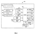
次に図2を参照すると、図2は、可搬型電子デバイスの実施形態を示し、参照200によって概して示される。可搬型電子デバイス200は、図1のディスプレイモジュール102に概して対応するディスプレイモジュール210を含む。可搬型電子デバイス200は、ワイヤレスWAN12(図1)との双方向通信のためのワイヤレスWAN通信サブシステム220と、WLAN14(図1)との双方向通信のためのWLAN通信サブシステム230とを含む。1つの実施形態によると、通信サブシステム220および230は、それぞれのアンテナ(図示せず)、RFトランシーバ(図示せず)、および例えば、デジタルシグナルプロセッサ(図示せず)によって実装されるなんらかの信号処理能力を含む。可搬型電子デバイス200はまた、可搬型電子デバイス200の全体の動作および機能を制御するように適切にプログラムされるマイクロプロセッサ240を含み、それは、以下においてより詳細に記述される。可搬型電子デバイス200は、フラッシュメモリ242、ランダムアクセスメモリ(RAM)244、補助入力/出力(I/O)サブシステム246(例えば、イーサネット(登録商標)などの外部通信リンク)、シリアルポート248(例えば、USBポート)、入力デバイス250(例えば、キーボードまたはキーパッド)、スピーカ252、マイクロホン254、短距離の通信サブシステム256(例えば、赤外線トランシーバ)、および参照258によって概して指定される任意の他のデバイスサブシステムなどの周辺デバイスまたはサブシステムを含む。
Referring now to FIG. 2, FIG. 2 shows an embodiment of a portable electronic device, generally indicated by
マイクロプロセッサ240は、フラッシュメモリ242(または、1つ以上の他のタイプの不揮発性メモリデバイス)中に保存されるコードまたはファームウェアによる保存されたプログラムの制御の下で動作する。図2において描かれるように、保存されたプログラム(例えば、ファームウェアまたは他のプログラミング)は、オペレーティングシステムプログラムまたはコードモジュール260と、参照262によって概して示される他のプログラムまたはソフトウェアアプリケーションとを含む。可搬型電子デバイス200のウェブ対応の実施形態または実装のためのソフトウェアアプリケーション262は、ウェブブラウザ264とEメールメッセージビュア266とを含む。ソフトウェアアプリケーション262の各々は、ソフトウェアアプリケーション262に対するユーザインタフェースにおけるテキストフィールド、入力フィールドなどの特定フィールドの配置を規定するレイアウト情報を含み得る。オペレーティングシステムコード260、特定のデバイスアプリケーション262のためのコード、またはそれらのコードのコンポーネントは、RAM244などの揮発性記憶媒体の中に一時的にロードされ得る。情報を伴う受信された通信信号および他のデータはまた、RAM244中に保存され得る。
マイクロプロセッサ240のための保存されたプログラム制御(すなわち、ソフトウェアアプリケーション262)はまた、基本的なデバイス動作を制御する所定のセットのアプリケーションまたはコードコンポーネントまたはソフトウェアモジュールを含む。基本的なデバイス動作は、例えば、データおよび音声通信アプリケーションであり、通常、製造工程の間にソフトウェアアプリケーション262として可搬型電子デバイス200にインストールされる。さらなるアプリケーションはまた、図1について上記されたネットワーク(補助I/Oサブシステム246、シリアルポート26、または短距離の通信サブシステム256)の動作を通して可搬型電子デバイス200上にロード(すなわち、ダウンロード)され得る。ダウンロードされたコードモジュールまたはコンポーネントはそれから、RAM244または不揮発性のプログラムメモリ(例えば、フラッシュメモリ242)に、ユーザによって(または自動的に)インストールされる。
The stored program control (ie, software application 262) for the
シリアルポート248は、デスクトップコンピュータ(図示せず)など別のデバイスとインタフェースするか、または同期させるために、USBタイプのインタフェースポートを含む。シリアルポート248は、外部デバイスまたはソフトウェアアプリケーションを通してプリファレンスを設定するために用いられる。シリアルポート248はまた、図1について上記されたワイヤレス通信ネットワークを介する以外に、可搬型電子デバイス200にユーザインタフェース情報を含む情報またはソフトウェアのダウンロードを提供することによって、可搬型電子デバイス200の能力を拡張するために用いられる。
短距離通信サブシステム256は、可搬型電子デバイス200と、様々なシステムまたは必ずしも同様なデバイスである必要がないデバイスとの間の通信のためにインタフェースを提供する。例えば、サブシステム256は、赤外線の通信リンクまたはチャネルを含む。
The short-
次に図4を参照すると、図4は、参照300によって概して示されるLCDディスプレイモジュールを含む、ディスプレイモジュール102(図1)または210(図2)の実施形態を示す。LCDディスプレイモジュール300は、(図3および図4に示されるように)LCDディスプレイ画面302を含み、図4において参照402によって概して示されるようにLCDドライバ回路を含む。ディスプレイモジュール300のこの実施形態によると、LCDディスプレイ画面302は、透過性モードのノーマルブラック液晶ディスプレイ(LCD)を含む。透過性モードのLCD画面302において、液晶エレメントはライトバルブとして機能し、電力がまったく適用されないとき、画面は通常黒である。電力が適用されるときに、液晶エレメントは配向され、光(例えば、バックライトからの光)は、通過することが可能となり、エレメントは照明されて、例えば、モノクロのディスプレイ画面に対しては白色、またはカラーディスプレイ画面に対しては赤色、青色、または緑色(または、それらの組合せ)である。
Referring now to FIG. 4, FIG. 4 illustrates an embodiment of the display module 102 (FIG. 1) or 210 (FIG. 2) that includes the LCD display module generally indicated by
図3を参照して、LCDディスプレイ画面302は、液晶ディスプレイ(LCD)パネル304と、図3の参照306a、306b、306c、および306dによって個々に示される、1つ以上のバックライト306を含む。液晶パネル304は、当業者によって理解されるように、サンドイッチ構成または層構成を用いて構築される。示されるように、LCDパネル304は、行および列を含むマトリックスとして、例えば、画素またはピクセルに分割される。液晶ディスプレイパネル304は、参照310a、310b、310c…310k、312a、312b、312c…312h、314a、314b、314c…314g、316a、316b、316c…316fによって示される、ピクセルのいくつかを示す部分的な断面図を含む。ピクセルの各々は、3つまたは4つのサブピクセルであって、各サブピクセルは、色エレメント(例えば、赤色、緑色、および青色)を提供する、サブピクセルをさらに含み得る。各ピクセルまたはサブピクセルは、ドライバ回路402におけるトランジスタによって(以下においてより詳細に記述されるように)制御される。
Referring to FIG. 3, the
図4に戻って参照すると、図4は、ドライバ回路402に対する一実施形態を概略図の形式において示す。ドライバ回路402は、サブピクセルあたり少なくとも1つのトランジスタを利用する、アクティブマトリックスLCD技術を含み、マイクロプロセッサユニット(MPU)またはマイクロコントローラユニット(MCU)404を含む。マイクロプロセッサ404は、LCDディスプレイモジュール300に対する制御およびディスプレイ機能を提供するために、保存されたプログラム制御の下で動作する。LCDドライバ回路402は、参照408によって示されるMPUインタフェースを介して、マイクロプロセッサ404に連結されるLCDドライバ/コントローラ406を含む。MPUインタフェース408は、マイクロプロセッサ404からの信号およびデータを、LCDドライバ/コントローラ406のためのLCDドライバデータへと変換する。示されるように、LCDドライバ回路402は、ディスプレイタイミング回路410およびロジックコントローラ412を含む。ディスプレイタイミング回路410は、MPUインタフェース408を介してマイクロプロセッサ404に連結されるロジックコントローラ412の制御の下で、LCDドライバ/コントローラ406に対してタイミング(例えば、リフレッシュ)信号を生成する。LCDドライバ/コントローラ406は、LCD画面302上でディスプレイされるデータに対するフレームバッファとして用いられるRAMを含む。1つの実施形態において、LCDドライバ/コントローラ406と関連づけられる機能性のいくつかまたはすべては、マイクロプロセッサ240(図2)を制御するために用いられる、ファームウェアまたは他のプログラミングと組合され得るか、または統合され得る。
Referring back to FIG. 4, FIG. 4 illustrates one embodiment for the
図4に示されるように、LCDドライバ回路402はまた、ソースドライバ回路414およびゲートドライバ回路416を含む。ソースドライバ回路414は、LCD画面302におけるピクセル(およびサブピクセル)のトランジスタの1つの端子(すなわち、ソース端子)を駆動するように機能する。同様に、ゲートドライバ回路416は、LCD画面302におけるピクセル(およびサブピクセル)のトランジスタの別の端子(すなわち、ゲート端子)を駆動するように機能する。この実施形態によると、LCD画面302は、160x160ピクセルを備え、各ピクセルは少なくとも3つのトランジスタを有する。ピクセルは、ソースドライバ回路414からの参照418により示される、160本のソースライン(すなわち、ソース0〜ソース159)と、ゲートドライバ回路416からの参照420により示される、480本のゲートライン(すなわち、ゲート0〜ゲート479)とによって制御される。
As shown in FIG. 4, the
動作において、LCDドライバ/コントローラ406は、マイクロプロセッサ404からデータを受取り、そのデータとディスプレイタイミング回路410からのデータとを組合せる。ディスプレイタイミング回路410は、LCD画面302に対するフレーム周波数を規定し、LCD画面302中のピクセルに対するトランジスタのソースおよびゲートが、いつ駆動されるかを決定する。LCDドライバ/コントローラ406は、マイクロプロセッサ404およびディスプレイタイミング回路410からのデータの組合せをドライバデータに変換し、そのデータを、ソースライン418およびゲートライン420をそれぞれ駆動する、ソースドライバ回路414およびゲートドライバ回路416に送る。
In operation, LCD driver /
次に図5を参照すると、図5は、1つの実施形態によるディスプレイモジュール300(図3)を伴う可搬型電子デバイスの動作を例示する。図5において、可搬型電子デバイスは、参照500によって概して示され、ディスプレイモジュールは、参照501によって概して示される。ディスプレイモジュール501に加えて、可搬型電子デバイス500は、キーパッドまたはキーボード510およびナビゲータパッド520を含む。上記されるように、ディスプレイモジュール501は、LCDディスプレイ画面502およびLCDドライバ回路(図示されないけれども、例えば、図4において描かれるLCDドライブ回路402に類似する)を含む。この実施形態によると、LCDディスプレイ画面502は、ディスプレイ画像を表示するかまたは提示し、参照530a、530b、および530cによって個別に示される、3つの一般のディスプレイ領域530を備える。以下においてより詳細に記述されるように、ディスプレイ領域530の各々は、個別に調整可能なまたは可変の輝度レベルまたは強度レベルを有するか、または他のディスプレイ区画のいずれかの輝度または強度と関係して調整可能でもある。1つの実施形態において、ディスプレイ区画530の各々は、ソフトウェア(例えば、ファームウェアまたは他の方法)において、それぞれのディスプレイ領域530に属するようにピクセルをマッピングまたは相関させることによって規定される。すなわち、それぞれのディスプレイ領域は、ソフトウェアにおいて、ディスプレイ画面502中のピクセルのグループにマップされるマスクまたはオーバーレイを含む。ディスプレイ画面502を制御するために、マスクまたはオーバーレイのマップを適用することによって、ディスプレイ画像(すなわち、ピクセルはディスプレイ画像を表す)は、それがLCDディスプレイ画面502上で表示されるときに、外観(すなわち、輝度レベル)において変更される。別の実施形態において、ディスプレイモジュール501は、3つ以上の分離されたLCDディスプレイ画面を備え、その画面は、物理的に結合されているけれども、マイクロプロセッサ240(図2)の制御下で機能する個別のLCDドライバ回路を有する。
Reference is now made to FIG. 5, which illustrates the operation of a portable electronic device with a display module 300 (FIG. 3) according to one embodiment. In FIG. 5, the portable electronic device is generally indicated by
図5を参照すると、ディスプレイ領域530bは、現在、ユーザがテキストを入力(例えば、「Hi Bob How are y…」)している領域または区画、すなわち、フォーカス領域または関心のある領域を備え、この実施形態によると、ディスプレイ領域530bは、標準または最大の輝度レベルで提示(すなわち、表示)される。2つの他のディスプレイ領域530aおよび530cは、非フォーカスまたは関心のない領域または区画を表し、そしてこの実施形態によれば、これらのディスプレイ領域は、例えば、フォーカス領域(すなわち、ディスプレイ領域530b)の輝度レベルと比較して減少されるか、またはより減光された輝度レベルで提示される。従って、フォーカス領域530bの外側の領域は、それらの領域が通常はどのように見えるかと比較して減光される。ユーザが、カーソルをディスプレイ画面502上で移動させる(例えば、キーパッド510またはナビゲータパッド520を用いる)ときに、マイクロプロセッサ240(図2)は、機能またはルーチンを含んでおり、ファームウェアまたは他のプログラミングの制御下において、機能またはルーチンを実行する。それらは、フォーカスポイントを追跡し、ディスプレイ画面502(すなわち、ピクセル)を制御することにより、フォーカスポイントを伴うディスプレイ領域(例えば、ディスプレイ領域530b)における画像は、標準の輝度レベルで表示され、一方、ユーザのフォーカス領域から離れている、他のディスプレイ領域(例えば、530aおよび530c)を伴うディスプレイ画面502は、減光されるか、またはフォーカス領域に対する輝度レベルより少ない輝度レベルで現れる。ファームウェアまたは他のプログラミングの制御下において、非フォーカスディスプレイ領域530aおよび530cは、等しいか、または一様な輝度レベルに減光されるか、あるいはディスプレイ領域530bから最も遠く離れる、ディスプレイ領域530aおよび530cの部分が最も暗くなるように、連続的に減少する輝度を有する。非フォーカスディスプレイ領域530および530cの減光は、非フォーカスディスプレイ領域530aまたは530cのそれぞれにおけるピクセルの減光を通して、表示されているディスプレイ画像の外観を変更することによって、ファームウェア(または、他のプログラミング)の制御の下に達成される。この実施形態によると、ファームウェアまたは他プログラミングは、非フォーカスディスプレイ領域530cにおけるピクセルのすべてを減光するための機能またはコードコンポーネントを含み、ディスプレイ領域530bにおけるピクセルのほとんどを減光するための機能またはコードコンポーネント、および/またはディスプレイ領域530aにおけるピクセルのいくつか(例えば、フォーカスディスプレイ領域530bから最も遠いピクセル)を減光するための機能またはコードのコンポーネントを含む。上記されるように、減光機能は、LCDディスプレイ画面502にそのあと適用される、オーバーレイまたはマスクへピクセルをマッピングすることによって実装され得る。減光オーバーレイまたはマスクは、フォーカスポイントの位置に応じて変更されるか、または調整される。換言すると、LCDディスプレイ画面502は、ディスプレイ画像を変更するために制御され、すなわち、フォーカスディスプレイ領域の外側または関心のある領域の外側のディスプレイ画像の領域に相当するピクセルは、減光される(すなわち、より低い輝度レベルまたは強度レベルを提供するために制御される)。別の実施形態において、ディスプレイ領域530a、530b、および530cは、規定される境界を有せず、LCDディスプレイ画面502は、連続的に可変の輝度を提供するように制御され、選択された領域またはフォーカス領域(例えば、ディスプレイ領域530b)から離れるに従って次第にフェードするようなディスプレイ画像を生じるように制御される。別の実施形態において、ディスプレイ領域530a、530b、および530cは、垂直または他のすべての方向において構成される。別の実施形態において、ディスプレイ領域530a、530b、または530cに対するピクセルは、いかなる形またはサイズ、例えば、正方形、長方形など、においても、マップされるか、または構成される。別の実施形態において、この方法と関連づけられる処理は、LCDドライバ/コントローラ406(図4)の機能によって一部分は実装され得る。
Referring to FIG. 5, the
次に図6を参照すると、図6は、ユーザのフォーカスポイント(すなわち、関心のある領域またはアクティビティの領域)を決定し、それに応じてディスプレイ画面502の輝度レベルを調整するための方法の一実施形態をフローチャート形式において示す。この実施形態による方法は、参照600によって概して示される。
Referring now to FIG. 6, FIG. 6 illustrates one implementation of a method for determining a user's focus point (ie, an area of interest or an area of activity) and adjusting the brightness level of the
図6に示されるように、方法600による最初のステップまたは動作は、ユーザがディスプレイ画面に触れたかまたは起動させたかを決定する(判断ブロック602)、制御回路(すなわち図2の、保存されたプログラム制御の下で動作するマイクロプロセッサ240)を含む。ユーザが、ディスプレイ画面に触れた(判断ブロック602において決定されるような)場合、ブロック608における次の動作は、ユーザに対するフォーカスポイントをアップデートするか、または規定する制御回路(すなわち保存されたプログラム制御またはファームウェアの下で動作するマイクロプロセッサ240)を含む。ユーザがディスプレイ画面に触れなかった(すなわち、判断ブロック602において決定されるような)場合、判断ブロック604における次の動作は、ユーザがディスプレイ画面の上でスクロールするか否かを決定することを含む。ユーザがスクロールする(判断ブロック604において決定されるような)場合、ブロック608における次の動作は、フォーカスポイントをアップデートすることを含む。ユーザがスクロールしない(すなわち、判断ブロック604において決定されるような)場合、次の動作は、ユーザがデータを入力するか否かを決定する(判断ブロック606)ために、ファームウェアまたは他のプログラミングにおいてコード化された機能を実行するマイクロプロセッサを含む。ユーザがデータを入力する場合、ブロック608において、マイクロプロセッサがフォーカスポイントをアップデートする(すなわち、アクティビティインジケータはアップデートされる)。ユーザがデータを入力しない場合、マイクロプロセッサは、例えば、ファームウェアまたは他のプログラミングにおいてコード化されたポーリングループにおいて、ブロック602、604、または606と関連づけられる動作を繰り返す。
As shown in FIG. 6, the first step or action according to
再び図6を参照すると、ステップ608において、フォーカスポイントがアップデートされたあと、判断ブロック610における次の動作は、可搬型電子デバイス500(図5)のためのディスプレイ画面502(図5)が、可変の輝度または可変の強度の動作のモードに設定されるか否かを決定することを含む。可変の強度のモードに設定される(例えば、セットアップ画面を通してユーザによって設定される)場合、ブロック612における次の動作は、フォーカスポイントを伴う関心のある領域付近の外側のディスプレイ領域(例えば、図5におけるディスプレイ領域530)を減光する制御回路(すなわち、保存されたプログラム制御の下で動作するマイクロプロセッサ240)を含む。上記されるように、1つの実施形態において、減光機能は、ディスプレイ画面に対するピクセルをオーバーレイまたはマスクにマップすることを含み、オーバーレイまたはマスクはそれから、変更されたディスプレイ画像を提示するためにディスプレイ画面に適用される、すなわち、ディスプレイ画像は区画を有し、その区画は、減光されるか、あるいはフォーカスポイント区画または関心のある区画と同じ明るさではないように提示される。可変の強度モードが設定されない場合、ステップ614における次の動作は、フォーカスポイントの外側のディスプレイ領域を、一様な強度または輝度レベルに維持する制御回路を含む。それから処理は、例えば、マイクロプロセッサによって実行されるポーリングループによって、ステップ602に進む。この方法600は、可搬型電子デバイス200(図2)のためのマイクロプロセッサ240(図2)によって、一般に1秒あたり数回実行される。この方法600は、オペレーティングシステムソフトウェアまたはコード260(図2)あるいはソフトウェアアプリケーション262(図2)の1つにおける、いずれかの一部として一般に実装される。
Referring again to FIG. 6, after the focus point is updated in
次に図7を参照すると、図7は、別の実施形態によるディスプレイモジュールを示し、参照700によって概して示される。ディスプレイモジュール700は、放射性のディスプレイ画面702を含み、照明エレメントの各々、すなわちピクセルが、図7における参照704によって示される有機発光ダイオードまたはOLEDを含む。ピクセルは、710a、710b、710c、710d、…として個々に示される複数の行710と、720a、720b、720c、720d、…として個々に示される複数の列720とを含むマトリックスにおいて配列される。OLEDの704は、減光または輝度制御のために個々に制御され、例えば、図7における参照706によって示される可変の電圧ドライブ回路を用いて制御される。上記と同様な方法において、ディスプレイ画面702は、2つ以上のディスプレイ領域に分けられ、照明エレメント(すなわち、OLEDの704)は、ディスプレイ領域の各々に対してマップされる。図6について上記されたプロセスによると、ファームウェアまたは他のプログラミングの制御下で、OLEDの704の各々の輝度レベル(すなわち、減光)は、例えば、フォーカスポイントに関連して変わる。OLEDの704の輝度レベルまたは減光レベルは、マイクロプロセッサ240(図2)によって実行される機能またはコードコンポーネントによって、個々またはグループにおいて変えられるか、あるいは制御され、マイクロプロセッサ240は、可変の電圧ドライブ回路706に、例えば、i/oマップされたデバイスか、またはアドレスマップされたデバイスとしてインタフェースされる。別の実施形態によると、OLEDは、他のタイプの発光ダイオードまたは照明デバイスによって置換えられ、それらの照明手段は、ディスプレイ画面702において、個々に制御可能なピクセルを実装する。
Referring now to FIG. 7, FIG. 7 shows a display module according to another embodiment, generally indicated by
次に図8を参照すると、図8は、別の実施形態によるディスプレイモジュールを示し、参照800によって概して示される。この実施形態によるディスプレイモジュール800は、ディスプレイ画面802および複数のライティング構成要素810を含む。ディスプレイ画面802は、図3のLCDパネル304において示されるようなピクセル310a、310b、310c・・・を実装する、透過ライトバルブエレメントの配列を含む透過型ディスプレイ(例えば、液晶ディスプレイ)を含む。ライティング構成要素810は、背後からディスプレイ画面802を照明するバックライト構成要素であり、参照810a、810b、810c、810d、810e、および810fによって個々に示される。図8に示されるように、ライティング構成要素810(すなわち、照明エレメント)は、ディスプレイ画面802の両側下部に配置されて、ディスプレイ画面802に発光するか、または照明するために機能するか、あるいは背後から画面802の一部として発光するか、または照明するために機能する。図8に示されるように、810aから810cまでの3つのライティング構成要素は、ディスプレイ画面802の右手側の下に配置され、810dから810fまでの3つのライティング構成要素は、ディスプレイ画面802の左手側の下に配置される。この実施形態による、ディスプレイ画面802は、3つのディスプレイ領域830に分割され、参照830a、830b、および830cによって個々にそれぞれ示される。フォーカスポイント(すなわち、関心のある領域)は、図5について上記された類似の方法において、ディスプレイ領域830に対して決定される。フォーカスポイントを伴うディスプレイ領域830に基づいて、他の2つのディスプレイ領域830に対するライティング構成要素810は、電力消費量を減少させるために減光される。例えば、ディスプレイ領域830cがフォーカスポイントを有する場合、ライティング構成要素810aおよび810fは、ディスプレイ領域830aに対して減光される。他の2つのライティング構成要素810b、および/または810eもまた、電力を節約するために減光され得る。別の実施形態において、フォーカスポイント(すなわち、関心のある領域)が、例えば、ディスプレイ領域830cの左手側に位置する場合、右手側のライティング構成要素810cはまた、減光され得る。ライティング構成要素810は、照明エレメントの各々に適用される電圧レベルを変化することによって減光される。1つの実施形態において、ライティング構成要素810の各々は、アナログ電圧端子またはポートに連結され、アナログ電圧レベルは、ファームウェア機能または他のプログラミングコードコンポーネントの制御下で動作するマイクロプロセッサ(例えば、図2におけるマイクロプロセッサ240)によって調整されるか、または変化される。従って、図8のディスプレイ画面802は、ディスプレイ画面802においてバックライト構成要素810が、フォーカス領域の外側で減光を実装するために制御されることを除いて、LCDパネルにおいてピクセルを実装するバルブエレメントを制御する、図3のディスプレイ画面302に類似する。
Referring now to FIG. 8, FIG. 8 shows a display module according to another embodiment, generally indicated by
1つの実施形態において、フォーカスポイントまたは関心のある領域は、上記されるように、カーソルの位置に基づいて決定される。フォーカスポイントは、他の実施形態に従って、様々なタイプのメカニズムを用いて決定され得る。1つの実施形態において、フォーカスポイントまたは関心のある領域は、アプリケーションレイヤに従って、例えば、Eメールウィンドウが多くのアプリケーションウィンドウまたは画面からオープンされるか、または選択されるかに従って、決定される。別の実施形態において、フォーカスポイントまたは関心のある領域は、フォーカスポイントまたはユーザの目の位置を追跡するトラッキングメカニズムによって作成される。トラッキングメカニズムは、ユーザによって身につけられる装置またはユーザの目の動きおよびフォーカス位置を追跡するリモートインタフェースを含み得る。ユーザの目の決定されたフォーカス位置は、コントローラ(例えば、図2におけるマイクロプロセッサ240)へ送信されるか、さもなければ伝わり、ファームウェア機能または他のプログラミングルーチンは、ディスプレイ画面上の対応するフォーカスポイントまたは関心のある領域を計算するか、または決定し、例えば図5について上記されるように、ディスプレイ画面の減光を制御するためにそれから用いられる。別の実施形態において、トラッキングメカニズムは、ユーザの目のイメージを撮り、イメージまたは複数イメージを、リアルタイム処理のための機能またはモジュールを含むオペレーティングシステムソフトウェアに送るカメラを備える。画像処理ソフトウェアは、イメージから現在のフォーカスポイントを計算し、このフォーカスポイントは、例えば、上記されるように、ディスプレイ画面の減光を制御するために用いられる。画像処理ソフトウェアは、フォーカスポイントをピクセルとして精細化し得るか、または誤差の量を表す半径によって円形の領域として規定し得る。
In one embodiment, the focus point or region of interest is determined based on the cursor position, as described above. The focus point may be determined using various types of mechanisms according to other embodiments. In one embodiment, the focus point or region of interest is determined according to the application layer, for example, according to whether an email window is opened or selected from many application windows or screens. In another embodiment, the focus point or region of interest is created by a tracking mechanism that tracks the position of the focus point or the user's eye. The tracking mechanism may include a device worn by the user or a remote interface that tracks the user's eye movement and focus position. The determined focus position of the user's eye is transmitted to or otherwise communicated to a controller (eg,
別の実施形態において、フォーカスポイントは、「マウストレイル(mouse trail)」として処理され、トラッキングメカニズム(例えば、上記されるような)は、ユーザの目の動きを追跡する。ユーザがその目によってディスプレイ画面を横切ってスクロールするときに、ユーザは、フォーカスした画面上の場所はまだ明るいけれども、例えば、規定のレートにおいて減光機能を被っていることを周辺視覚において気づく。実施形態によると、オペレーティングシステムソフトウェアは、特定の期間(例えば、履歴)に渡ってフォーカスポイントを追跡し、それに応じてディスプレイ画面の減光を変更するマスクを利用する。 In another embodiment, the focus point is treated as a “mouse trail” and a tracking mechanism (eg, as described above) tracks the movement of the user's eyes. When the user scrolls across the display screen with his eyes, the user will notice in ambient vision that, for example, the focused location on the screen is still bright, but has suffered a dimming function at a defined rate, for example. According to an embodiment, the operating system software utilizes a mask that tracks the focus point over a specific period (eg, history) and changes the dimming of the display screen accordingly.
本出願の上記された実施形態は、例示のみを意図される。代替、改変、および変更は、添付の特許請求の範囲によって定義される適用範囲を逸脱することなく、当業者によって特定の実施形態にもたらされ得る。 The above-described embodiments of the present application are intended to be examples only. Alternatives, modifications, and changes may be made to a particular embodiment by those skilled in the art without departing from the scope defined by the appended claims.
Claims (23)
ディスプレイ画面と、
コントローラであって、該コントローラは、情報を受取るための入力と、該ディスプレイ画面へディスプレイ情報を出力するための該ディスプレイ画面へ連結される出力と、を有する、コントローラと
を備え、
該コントローラは、該ディスプレイ画面上の関心のある領域を決定するための構成要素を含み、
該コントローラは、該関心のある領域の外側にある該ディスプレイ画面の少なくとも一部分を減光するための構成要素を有する、ディスプレイモジュール。 A display module,
A display screen;
A controller comprising: an input for receiving information; and an output coupled to the display screen for outputting display information to the display screen;
The controller includes components for determining a region of interest on the display screen;
The controller has a component for dimming at least a portion of the display screen that is outside the region of interest.
該ディスプレイ上にイメージを表示するステップと、
該ディスプレイ上の関心のある領域を規定するステップと、
該関心のある領域の外側に該表示されるイメージの少なくとも一部分を減光するステップと
を包含する、方法。 A method for controlling a display for an electronic device, the method comprising:
Displaying an image on the display;
Defining a region of interest on the display;
Dimming at least a portion of the displayed image outside the region of interest.
入力デバイスと、
液晶ディスプレイであって、ディスプレイ画面を含む、液晶ディスプレイと、
コントローラであって、該コントローラは、情報を受取るための入力と、該ディスプレイ画面へディスプレイ情報を出力するための該ディスプレイ画面へ連結される出力とを有する、コントローラと
を備え、
該コントローラは、該ディスプレイ画面上の関心のある領域を決定するための構成要素を含み、該コントローラは、該関心のある領域の外側にある該ディスプレイ画面の少なくとも一部分を減光するための構成要素を有する、可搬型電子デバイス。 A portable electronic device,
An input device;
A liquid crystal display, including a display screen, and a liquid crystal display;
A controller comprising: an input for receiving information; and an output coupled to the display screen for outputting display information to the display screen;
The controller includes a component for determining a region of interest on the display screen, and the controller includes a component for dimming at least a portion of the display screen outside the region of interest. A portable electronic device.
Applications Claiming Priority (2)
| Application Number | Priority Date | Filing Date | Title |
|---|---|---|---|
| US75240605P | 2005-12-22 | 2005-12-22 | |
| PCT/CA2006/002095 WO2007071049A1 (en) | 2005-12-22 | 2006-12-21 | Method and apparatus for reducing power consumption in a display for an electronic device |
Related Child Applications (1)
| Application Number | Title | Priority Date | Filing Date |
|---|---|---|---|
| JP2009061776A Division JP2009193075A (en) | 2005-12-22 | 2009-03-13 | Method and device for reducing power consumption in display for electronic device |
Publications (2)
| Publication Number | Publication Date |
|---|---|
| JP2009520993A true JP2009520993A (en) | 2009-05-28 |
| JP2009520993A5 JP2009520993A5 (en) | 2011-02-24 |
Family
ID=38188227
Family Applications (2)
| Application Number | Title | Priority Date | Filing Date |
|---|---|---|---|
| JP2008546057A Pending JP2009520993A (en) | 2005-12-22 | 2006-12-21 | Method and apparatus for reducing power consumption in a display for an electronic device |
| JP2009061776A Pending JP2009193075A (en) | 2005-12-22 | 2009-03-13 | Method and device for reducing power consumption in display for electronic device |
Family Applications After (1)
| Application Number | Title | Priority Date | Filing Date |
|---|---|---|---|
| JP2009061776A Pending JP2009193075A (en) | 2005-12-22 | 2009-03-13 | Method and device for reducing power consumption in display for electronic device |
Country Status (6)
| Country | Link |
|---|---|
| US (1) | US20070146344A1 (en) |
| EP (1) | EP1964103A4 (en) |
| JP (2) | JP2009520993A (en) |
| KR (2) | KR20100031555A (en) |
| CN (2) | CN101385071B (en) |
| WO (1) | WO2007071049A1 (en) |
Cited By (4)
| Publication number | Priority date | Publication date | Assignee | Title |
|---|---|---|---|---|
| JP2010224928A (en) * | 2009-03-24 | 2010-10-07 | Toshiba Corp | Portable information processor |
| JP2011203707A (en) * | 2010-03-24 | 2011-10-13 | Samsung Electronics Co Ltd | Display apparatus and method of controlling display apparatus |
| JP2011237690A (en) * | 2010-05-12 | 2011-11-24 | Canon Inc | Image processing device and image processing method |
| WO2013099402A1 (en) * | 2011-12-26 | 2013-07-04 | 日本電気株式会社 | Information processing device, light source control method, and program |
Families Citing this family (97)
| Publication number | Priority date | Publication date | Assignee | Title |
|---|---|---|---|---|
| US7153286B2 (en) | 2002-05-24 | 2006-12-26 | Baxter International Inc. | Automated dialysis system |
| US7616882B2 (en) * | 2006-08-10 | 2009-11-10 | Research In Motion Limited | Method and apparatus for power management in an electronic device |
| US8225229B2 (en) * | 2006-11-09 | 2012-07-17 | Sony Mobile Communications Ab | Adjusting display brightness and/or refresh rates based on eye tracking |
| US20090113335A1 (en) * | 2007-10-30 | 2009-04-30 | Baxter International Inc. | Dialysis system user interface |
| US20090158221A1 (en) * | 2007-12-17 | 2009-06-18 | Nokia Corporation | Device feature manipulation based on presented content |
| JP5122993B2 (en) * | 2008-01-30 | 2013-01-16 | 京セラ株式会社 | Portable information processing device |
| KR101495164B1 (en) * | 2008-04-10 | 2015-02-24 | 엘지전자 주식회사 | Mobile terminal and method for processing screen thereof |
| JP2010039848A (en) * | 2008-08-06 | 2010-02-18 | Toshiba Corp | Electronic equipment |
| EP3564939B1 (en) | 2008-09-30 | 2022-11-09 | Dolby Laboratories Licensing Corp. | Improved power management for modulated backlights |
| JP4816713B2 (en) * | 2008-11-25 | 2011-11-16 | ソニー株式会社 | Information processing apparatus, information processing method, and information processing program |
| KR101563523B1 (en) * | 2009-01-30 | 2015-10-28 | 삼성전자주식회사 | Mobile terminal having dual touch screen and method for displaying user interface thereof |
| JP2011002520A (en) * | 2009-06-16 | 2011-01-06 | Sony Corp | Self-luminous display device, power consumption reduction method, and program |
| US20110181611A1 (en) * | 2009-06-30 | 2011-07-28 | Yanli Zhang | User interface and control of segmented backlight display |
| US8224391B2 (en) * | 2009-07-20 | 2012-07-17 | Lg Electronics Inc. | Mobile terminal having an LED backlight unit |
| KR101658546B1 (en) * | 2009-07-20 | 2016-09-21 | 엘지전자 주식회사 | Mobile terminal with an led backlight unit |
| JP2011095614A (en) * | 2009-10-30 | 2011-05-12 | Aisin Aw Co Ltd | Display control device, navigation device, and display control method |
| CN102135933A (en) * | 2010-01-21 | 2011-07-27 | 微盟电子(昆山)有限公司 | Method for effectively warning power state of battery |
| US8706911B2 (en) * | 2010-01-27 | 2014-04-22 | Industrial Technology Research Institute | Power saving display information converting system and method |
| JP2011215206A (en) * | 2010-03-31 | 2011-10-27 | Fujitsu Ten Ltd | Display apparatus and display method |
| JP2011232130A (en) * | 2010-04-27 | 2011-11-17 | Fujitsu Ten Ltd | Display device and display method |
| KR20120007686A (en) * | 2010-07-15 | 2012-01-25 | 삼성전자주식회사 | Method and apparatus for controlling function in a touch device |
| KR20120054750A (en) * | 2010-11-22 | 2012-05-31 | 삼성전자주식회사 | Method and apparatus for selective display |
| EP2469503A1 (en) * | 2010-12-21 | 2012-06-27 | Thomson Licensing | Computer device comprising a first and a second display screen, method of operating the computer device and computer readable storage medium. |
| CN102122489A (en) * | 2011-03-16 | 2011-07-13 | 中兴通讯股份有限公司 | Method and terminal for automatically lowering power consumption of organic light-emitting display (OLED) |
| CN102736722B (en) * | 2011-03-31 | 2015-04-29 | 国基电子(上海)有限公司 | An electronic device with double display screens and a method for controlling screen display thereof |
| US8687840B2 (en) * | 2011-05-10 | 2014-04-01 | Qualcomm Incorporated | Smart backlights to minimize display power consumption based on desktop configurations and user eye gaze |
| CN102915105A (en) * | 2011-08-01 | 2013-02-06 | 浪潮乐金数字移动通信有限公司 | Electronic device and power saving method thereof |
| CN102915104A (en) * | 2011-08-01 | 2013-02-06 | 浪潮乐金数字移动通信有限公司 | Terminal device and display control method of display screen |
| CN102917140A (en) * | 2011-08-01 | 2013-02-06 | 浪潮乐金数字移动通信有限公司 | Power-saving display method for electronic terminal, electronic terminal and mobile communication terminal |
| KR101929426B1 (en) * | 2011-09-07 | 2018-12-17 | 삼성디스플레이 주식회사 | Display device and driving method thereof |
| WO2013080444A1 (en) * | 2011-11-29 | 2013-06-06 | パナソニック株式会社 | Display control device, display control method, and display control program |
| US9459781B2 (en) | 2012-05-09 | 2016-10-04 | Apple Inc. | Context-specific user interfaces for displaying animated sequences |
| US9564085B2 (en) * | 2012-05-27 | 2017-02-07 | Dialog Semiconductor Inc. | Selective dimming to reduce power of a light emitting display device |
| US9253524B2 (en) * | 2012-07-20 | 2016-02-02 | Intel Corporation | Selective post-processing of decoded video frames based on focus point determination |
| CN103576831A (en) * | 2012-08-09 | 2014-02-12 | 英华达(上海)科技有限公司 | Power-saving method for screen |
| CN103631552B (en) * | 2012-08-28 | 2021-05-07 | 刘彬 | Method and device for realizing energy conservation and fine control of display module |
| US9666119B2 (en) * | 2012-08-30 | 2017-05-30 | Apple Inc. | Systems and methods for controlling current in display devices |
| EP2717474A1 (en) * | 2012-10-02 | 2014-04-09 | Thomson Licensing | Multiple function arrangement for electronic apparatus and method thereof |
| CN103777742B (en) * | 2012-10-19 | 2017-08-25 | 广州三星通信技术研究有限公司 | Method and display device for providing user interface in a display device |
| CN104756041B (en) * | 2012-11-30 | 2018-07-17 | 汤姆逊许可公司 | The method and apparatus for showing content |
| US20140168279A1 (en) * | 2012-12-14 | 2014-06-19 | Hewlett-Packard Development Company, L.P. | Dimming a display device |
| CN102981596A (en) * | 2012-12-21 | 2013-03-20 | 东莞宇龙通信科技有限公司 | Terminal and screen interface display method |
| CN103176589B (en) * | 2013-03-04 | 2016-02-10 | 东莞宇龙通信科技有限公司 | Screen display method during a kind of content of edit and system |
| CN110427096B (en) * | 2013-05-16 | 2024-02-13 | 英特尔公司 | Automatically adjusting display area to reduce power consumption |
| CN103400568B (en) * | 2013-08-21 | 2016-09-28 | 魅族科技(中国)有限公司 | The control method of a kind of screen intensity and terminal |
| US9703355B2 (en) * | 2013-08-28 | 2017-07-11 | Qualcomm Incorporated | Method, devices and systems for dynamic multimedia data flow control for thermal power budgeting |
| CN103559694A (en) * | 2013-10-28 | 2014-02-05 | 四川大学 | OLED low power consumption method based on HSV color space |
| JP6167028B2 (en) * | 2013-11-29 | 2017-07-19 | 株式会社Nttドコモ | Display device and program |
| CN104700770A (en) * | 2013-12-10 | 2015-06-10 | 中国移动通信集团公司 | Web content-based LED screen brightness adjusting method and device |
| US10108324B2 (en) | 2014-05-22 | 2018-10-23 | Samsung Electronics Co., Ltd. | Display device and method for controlling the same |
| US10452253B2 (en) | 2014-08-15 | 2019-10-22 | Apple Inc. | Weather user interface |
| CN105489191A (en) * | 2014-09-18 | 2016-04-13 | 北京三星通信技术研究有限公司 | Display device and display method thereof |
| US9378688B2 (en) | 2014-11-24 | 2016-06-28 | Caterpillar Inc. | System and method for controlling brightness in areas of a liquid crystal display |
| US20160239091A1 (en) * | 2015-02-12 | 2016-08-18 | Qualcomm Incorporated | Controlled display of content on wearable displays |
| CN104811532A (en) * | 2015-03-23 | 2015-07-29 | 努比亚技术有限公司 | Terminal screen display parameter adjustment method and device |
| CN104809347B (en) * | 2015-04-28 | 2018-08-24 | 南京巨鲨显示科技有限公司 | A kind of implementation method that control display outburst area is shown |
| EP4321088A3 (en) | 2015-08-20 | 2024-04-24 | Apple Inc. | Exercise-based watch face |
| KR101685989B1 (en) | 2016-01-04 | 2016-12-13 | 엘지전자 주식회사 | Mobile terminal |
| KR102501123B1 (en) * | 2016-01-04 | 2023-02-17 | 엘지전자 주식회사 | Mobile terminal |
| KR102501121B1 (en) * | 2016-01-04 | 2023-02-17 | 엘지전자 주식회사 | Mobile terminal |
| US10025938B2 (en) * | 2016-03-02 | 2018-07-17 | Qualcomm Incorporated | User-controllable screen privacy software |
| CN106020760A (en) * | 2016-05-31 | 2016-10-12 | 珠海市魅族科技有限公司 | Multi-display-brightness data display method and device |
| CN107527051B (en) * | 2016-06-21 | 2020-05-15 | 四川大学 | OLED low-power-consumption display method for sensing image content |
| CN106125934A (en) * | 2016-06-28 | 2016-11-16 | 广东欧珀移动通信有限公司 | Control method, control device and electronic installation |
| CN106228946B (en) * | 2016-07-22 | 2019-02-15 | Oppo广东移动通信有限公司 | Control method and control device |
| WO2018020368A1 (en) * | 2016-07-29 | 2018-02-01 | Semiconductor Energy Laboratory Co., Ltd. | Display method, display device, electronic device, non-temporary memory medium, and program |
| EP3491639A4 (en) | 2016-09-23 | 2019-07-31 | Apple Inc. | Watch theater mode |
| DE102016124125A1 (en) * | 2016-12-13 | 2018-06-14 | International Automotive Components Group Gmbh | Automotive interior trim part |
| CN106782305A (en) * | 2017-01-22 | 2017-05-31 | 努比亚技术有限公司 | A kind of display methods and terminal |
| CN106842752B (en) * | 2017-04-24 | 2019-06-07 | 京东方科技集团股份有限公司 | Display panel, display device and its display methods |
| DK179412B1 (en) | 2017-05-12 | 2018-06-06 | Apple Inc | Context-Specific User Interfaces |
| DK179555B1 (en) | 2017-05-16 | 2019-02-13 | Apple Inc. | User interface for a flashlight mode on an electronic device |
| US10565943B2 (en) | 2017-06-27 | 2020-02-18 | Wuhan China Star Optoelectronics Technology Co., Ltd. | Device and method for reducing power consumption of liquid crystal display, and liquid crystal display |
| CN107093407A (en) * | 2017-06-27 | 2017-08-25 | 武汉华星光电技术有限公司 | Lower power consumption device and method of reducing power consumption, the liquid crystal display of liquid crystal display |
| CN107436660A (en) * | 2017-07-12 | 2017-12-05 | 广东欧珀移动通信有限公司 | A kind of method for reducing temperature rise, computer-readable recording medium, electronic equipment |
| CN107393465B (en) * | 2017-07-24 | 2019-02-19 | 武汉华星光电技术有限公司 | OLED display and its driving method |
| TWI625716B (en) * | 2017-08-31 | 2018-06-01 | Chipone Technology Beijing Co Ltd | Method and device for saving power consumption of panel |
| KR102532972B1 (en) * | 2017-12-29 | 2023-05-16 | 엘지디스플레이 주식회사 | Compensation Method for Display and the Display comprising a memory storing compensation values |
| CN108231038A (en) * | 2018-01-23 | 2018-06-29 | 北京小米移动软件有限公司 | Screen luminance adjustment method and device |
| US11327650B2 (en) | 2018-05-07 | 2022-05-10 | Apple Inc. | User interfaces having a collection of complications |
| KR102553107B1 (en) | 2018-07-25 | 2023-07-10 | 삼성전자주식회사 | A display apparatus and a method for displaying an image thereof |
| GB2576060A (en) * | 2018-07-31 | 2020-02-05 | Continental Automotive Gmbh | Head-Up Display System |
| US11131967B2 (en) | 2019-05-06 | 2021-09-28 | Apple Inc. | Clock faces for an electronic device |
| WO2020227330A1 (en) | 2019-05-06 | 2020-11-12 | Apple Inc. | Restricted operation of an electronic device |
| US11960701B2 (en) | 2019-05-06 | 2024-04-16 | Apple Inc. | Using an illustration to show the passing of time |
| CN110517645A (en) * | 2019-08-30 | 2019-11-29 | 京东方科技集团股份有限公司 | Display device, electronic equipment and backlight dynamic area brightness adjusting method |
| DK180684B1 (en) | 2019-09-09 | 2021-11-25 | Apple Inc | Techniques for managing display usage |
| CN110867172B (en) * | 2019-11-19 | 2021-02-26 | 苹果公司 | Electronic device for dynamically controlling standard dynamic range and high dynamic range content |
| US11302284B2 (en) | 2020-01-17 | 2022-04-12 | Microsoft Technology Licensing, Llc | Focus assist mode for user interfaces |
| US11372659B2 (en) | 2020-05-11 | 2022-06-28 | Apple Inc. | User interfaces for managing user interface sharing |
| DK202070625A1 (en) | 2020-05-11 | 2022-01-04 | Apple Inc | User interfaces related to time |
| WO2021231345A1 (en) | 2020-05-11 | 2021-11-18 | Apple Inc. | User interfaces for managing user interface sharing |
| CN114360471A (en) * | 2020-05-15 | 2022-04-15 | 华为技术有限公司 | Display adjustment method, device, system and storage medium |
| US11694590B2 (en) | 2020-12-21 | 2023-07-04 | Apple Inc. | Dynamic user interface with time indicator |
| US11720239B2 (en) | 2021-01-07 | 2023-08-08 | Apple Inc. | Techniques for user interfaces related to an event |
| US11921992B2 (en) | 2021-05-14 | 2024-03-05 | Apple Inc. | User interfaces related to time |
| US11783789B1 (en) * | 2022-05-13 | 2023-10-10 | Meta Platforms Technologies, Llc | Dynamic brightness compensation in display assembly |
Family Cites Families (12)
| Publication number | Priority date | Publication date | Assignee | Title |
|---|---|---|---|---|
| US5592193A (en) * | 1994-03-10 | 1997-01-07 | Chunghwa Picture Tubes, Ltd. | Backlighting arrangement for LCD display panel |
| CN1143163C (en) * | 1997-07-25 | 2004-03-24 | 精工爱普生株式会社 | Display and electronic device equipped with same |
| US6976212B2 (en) * | 2001-09-10 | 2005-12-13 | Xerox Corporation | Method and apparatus for the construction and use of table-like visualizations of hierarchic material |
| US20030052903A1 (en) * | 2001-09-20 | 2003-03-20 | Weast John C. | Method and apparatus for focus based lighting |
| US7064740B2 (en) * | 2001-11-09 | 2006-06-20 | Sharp Laboratories Of America, Inc. | Backlit display with improved dynamic range |
| US6801811B2 (en) * | 2001-12-27 | 2004-10-05 | Hewlett-Packard Development Company, L.P. | Software-directed, energy-aware control of display |
| US7036025B2 (en) * | 2002-02-07 | 2006-04-25 | Intel Corporation | Method and apparatus to reduce power consumption of a computer system display screen |
| US20040233146A1 (en) * | 2003-05-21 | 2004-11-25 | Nguyen Don J. | Selective window display |
| US7580033B2 (en) * | 2003-07-16 | 2009-08-25 | Honeywood Technologies, Llc | Spatial-based power savings |
| KR100607518B1 (en) | 2004-02-20 | 2006-08-02 | 엘지전자 주식회사 | Electro-luminescensce dispaly panel and method for driving the same |
| JP2005321664A (en) * | 2004-05-11 | 2005-11-17 | Hitachi Ltd | Image display apparatus |
| US7614011B2 (en) * | 2004-10-21 | 2009-11-03 | International Business Machines Corporation | Apparatus and method for display power saving |
-
2006
- 2006-12-21 US US11/614,278 patent/US20070146344A1/en not_active Abandoned
- 2006-12-21 EP EP06840522A patent/EP1964103A4/en not_active Ceased
- 2006-12-21 JP JP2008546057A patent/JP2009520993A/en active Pending
- 2006-12-21 WO PCT/CA2006/002095 patent/WO2007071049A1/en active Application Filing
- 2006-12-21 CN CN200680053269XA patent/CN101385071B/en active Active
- 2006-12-21 KR KR1020107004259A patent/KR20100031555A/en not_active Application Discontinuation
- 2006-12-21 CN CN201010575719XA patent/CN102073370A/en active Pending
- 2006-12-21 KR KR1020087017519A patent/KR101004307B1/en active IP Right Grant
-
2009
- 2009-03-13 JP JP2009061776A patent/JP2009193075A/en active Pending
Cited By (5)
| Publication number | Priority date | Publication date | Assignee | Title |
|---|---|---|---|---|
| JP2010224928A (en) * | 2009-03-24 | 2010-10-07 | Toshiba Corp | Portable information processor |
| JP2011203707A (en) * | 2010-03-24 | 2011-10-13 | Samsung Electronics Co Ltd | Display apparatus and method of controlling display apparatus |
| US8791964B2 (en) | 2010-03-24 | 2014-07-29 | Samsung Electronics Co., Ltd. | Display apparatus and method of controlling the same |
| JP2011237690A (en) * | 2010-05-12 | 2011-11-24 | Canon Inc | Image processing device and image processing method |
| WO2013099402A1 (en) * | 2011-12-26 | 2013-07-04 | 日本電気株式会社 | Information processing device, light source control method, and program |
Also Published As
| Publication number | Publication date |
|---|---|
| CN101385071B (en) | 2011-01-26 |
| EP1964103A4 (en) | 2009-02-25 |
| US20070146344A1 (en) | 2007-06-28 |
| CN101385071A (en) | 2009-03-11 |
| KR20080079325A (en) | 2008-08-29 |
| JP2009193075A (en) | 2009-08-27 |
| EP1964103A1 (en) | 2008-09-03 |
| WO2007071049A1 (en) | 2007-06-28 |
| CN102073370A (en) | 2011-05-25 |
| KR101004307B1 (en) | 2010-12-28 |
| KR20100031555A (en) | 2010-03-22 |
Similar Documents
| Publication | Publication Date | Title |
|---|---|---|
| JP2009520993A (en) | Method and apparatus for reducing power consumption in a display for an electronic device | |
| US7995050B2 (en) | Power saving display | |
| KR101997776B1 (en) | Method for reducing for consumption power of display unit and an electronic device thereof | |
| JP5770312B2 (en) | Reduced still image detection and resource usage on electronic devices | |
| US11308841B2 (en) | Display control device, display apparatus, non-transitory recording medium, and method for controlling display control device | |
| JP6407509B2 (en) | Control device and display device | |
| WO2017012310A1 (en) | Method and system for reducing power consumption of mobile terminal | |
| US20160314762A1 (en) | Display apparatus and method for controlling the same | |
| KR20110125261A (en) | Switching operating modes of liquid crystal displays | |
| KR20150049045A (en) | Method and apparautus for controlling the brightness of the screen in portable device | |
| US20180277046A1 (en) | Display backlight brightness adjustment | |
| CN103135742A (en) | Method for improving endurance of mobile terminal | |
| US20120169637A1 (en) | Method and apparatus for reducing power consumption in mobile terminal | |
| US9881566B2 (en) | Display device, electronic apparatus, and control method for display device | |
| JP2008170935A (en) | Display device, control method thereof and drive device for display panel | |
| CN113160749B (en) | Display control device, display device, recording medium, and control method | |
| CA2531609A1 (en) | Method and apparatus for reducing power consumption in a display for an electronic device | |
| CN113534947A (en) | Eyeball tracking-based display backlight control method and equipment | |
| WO2019239903A1 (en) | Control device, display device, and control method | |
| CN110189723B (en) | Adjusting method, adjusting device, driving method and transparent display device | |
| CN114879927A (en) | Information screen display method and device, computer equipment and readable storage medium | |
| CN116486745A (en) | Display control method and device and electronic equipment | |
| US20070152955A1 (en) | Reduced power consumption display panel |
Legal Events
| Date | Code | Title | Description |
|---|---|---|---|
| A521 | Written amendment |
Free format text: JAPANESE INTERMEDIATE CODE: A523 Effective date: 20110106 |
|
| A131 | Notification of reasons for refusal |
Free format text: JAPANESE INTERMEDIATE CODE: A131 Effective date: 20110628 |
|
| A02 | Decision of refusal |
Free format text: JAPANESE INTERMEDIATE CODE: A02 Effective date: 20111226 |