JP2009520656A - Drinking equipment - Google Patents
Drinking equipment Download PDFInfo
- Publication number
- JP2009520656A JP2009520656A JP2008546641A JP2008546641A JP2009520656A JP 2009520656 A JP2009520656 A JP 2009520656A JP 2008546641 A JP2008546641 A JP 2008546641A JP 2008546641 A JP2008546641 A JP 2008546641A JP 2009520656 A JP2009520656 A JP 2009520656A
- Authority
- JP
- Japan
- Prior art keywords
- base
- nozzle
- closure
- overcap
- foil
- Prior art date
- Legal status (The legal status is an assumption and is not a legal conclusion. Google has not performed a legal analysis and makes no representation as to the accuracy of the status listed.)
- Withdrawn
Links
Images


Classifications
-
- B—PERFORMING OPERATIONS; TRANSPORTING
- B65—CONVEYING; PACKING; STORING; HANDLING THIN OR FILAMENTARY MATERIAL
- B65D—CONTAINERS FOR STORAGE OR TRANSPORT OF ARTICLES OR MATERIALS, e.g. BAGS, BARRELS, BOTTLES, BOXES, CANS, CARTONS, CRATES, DRUMS, JARS, TANKS, HOPPERS, FORWARDING CONTAINERS; ACCESSORIES, CLOSURES, OR FITTINGS THEREFOR; PACKAGING ELEMENTS; PACKAGES
- B65D47/00—Closures with filling and discharging, or with discharging, devices
- B65D47/04—Closures with discharging devices other than pumps
- B65D47/06—Closures with discharging devices other than pumps with pouring spouts or tubes; with discharge nozzles or passages
- B65D47/08—Closures with discharging devices other than pumps with pouring spouts or tubes; with discharge nozzles or passages having articulated or hinged closures
- B65D47/0804—Closures with discharging devices other than pumps with pouring spouts or tubes; with discharge nozzles or passages having articulated or hinged closures integrally formed with the base element provided with the spout or discharge passage
-
- B—PERFORMING OPERATIONS; TRANSPORTING
- B65—CONVEYING; PACKING; STORING; HANDLING THIN OR FILAMENTARY MATERIAL
- B65D—CONTAINERS FOR STORAGE OR TRANSPORT OF ARTICLES OR MATERIALS, e.g. BAGS, BARRELS, BOTTLES, BOXES, CANS, CARTONS, CRATES, DRUMS, JARS, TANKS, HOPPERS, FORWARDING CONTAINERS; ACCESSORIES, CLOSURES, OR FITTINGS THEREFOR; PACKAGING ELEMENTS; PACKAGES
- B65D47/00—Closures with filling and discharging, or with discharging, devices
- B65D47/04—Closures with discharging devices other than pumps
- B65D47/06—Closures with discharging devices other than pumps with pouring spouts or tubes; with discharge nozzles or passages
- B65D47/08—Closures with discharging devices other than pumps with pouring spouts or tubes; with discharge nozzles or passages having articulated or hinged closures
-
- B—PERFORMING OPERATIONS; TRANSPORTING
- B65—CONVEYING; PACKING; STORING; HANDLING THIN OR FILAMENTARY MATERIAL
- B65D—CONTAINERS FOR STORAGE OR TRANSPORT OF ARTICLES OR MATERIALS, e.g. BAGS, BARRELS, BOTTLES, BOXES, CANS, CARTONS, CRATES, DRUMS, JARS, TANKS, HOPPERS, FORWARDING CONTAINERS; ACCESSORIES, CLOSURES, OR FITTINGS THEREFOR; PACKAGING ELEMENTS; PACKAGES
- B65D2251/00—Details relating to container closures
- B65D2251/20—Sealing means
-
- B—PERFORMING OPERATIONS; TRANSPORTING
- B65—CONVEYING; PACKING; STORING; HANDLING THIN OR FILAMENTARY MATERIAL
- B65D—CONTAINERS FOR STORAGE OR TRANSPORT OF ARTICLES OR MATERIALS, e.g. BAGS, BARRELS, BOTTLES, BOXES, CANS, CARTONS, CRATES, DRUMS, JARS, TANKS, HOPPERS, FORWARDING CONTAINERS; ACCESSORIES, CLOSURES, OR FITTINGS THEREFOR; PACKAGING ELEMENTS; PACKAGES
- B65D2401/00—Tamper-indicating means
- B65D2401/15—Tearable part of the closure
-
- B—PERFORMING OPERATIONS; TRANSPORTING
- B65—CONVEYING; PACKING; STORING; HANDLING THIN OR FILAMENTARY MATERIAL
- B65D—CONTAINERS FOR STORAGE OR TRANSPORT OF ARTICLES OR MATERIALS, e.g. BAGS, BARRELS, BOTTLES, BOXES, CANS, CARTONS, CRATES, DRUMS, JARS, TANKS, HOPPERS, FORWARDING CONTAINERS; ACCESSORIES, CLOSURES, OR FITTINGS THEREFOR; PACKAGING ELEMENTS; PACKAGES
- B65D2547/00—Closures with filling and discharging, or with discharging, devices
- B65D2547/04—Closures with discharging devices other than pumps
- B65D2547/06—Closures with discharging devices other than pumps with pouring spouts ot tubes; with discharge nozzles or passages
Abstract
Description
本発明は、消費者が、「活動中」に、キャップが嵌められている容器から飲むことを可能にするように設計されたスポーツキャップまたはストローキャップとして知られるタイプの飲用備品または飲用ボトルのクロージャに関する。 The present invention relates to a closure of a drinking equipment or drinking bottle of the type known as a sports cap or straw cap designed to allow consumers to “drink” from the cap-fitted container “on the fly”. About.
かかるクロージャは、容器の首に嵌まる基部を有する。基部によって、外側シェルは、飲用オリフィスを画定するノズルまたはマウスピースを保持する。マウスピースは、消費者の口の中に受け取られるように形作られ、飲むことは、マウスピースを吸うことと、ボトルを搾ることとの組み合わせによって行われる。 Such a closure has a base that fits over the neck of the container. With the base, the outer shell holds a nozzle or mouthpiece that defines a drinking orifice. The mouthpiece is shaped to be received in the consumer's mouth and drinking is a combination of sucking the mouthpiece and squeezing the bottle.
かかるクロージャの設計において重要な多数の考慮点が存在する。これらは、容器の出荷時密閉および再密閉;クロージャおよび容器のコストおよび重さ;クロージャを作るために必要とされる成形のコスト、複雑さ、および効率;使用しないときのマウスピースの覆い;いたずら防止;ならびに小さな取り外し可能な部品によって作り出される、ゴミが散らかる問題および窒息の危険性を含む。 There are a number of important considerations in the design of such closures. These include: container shipping and resealing; closure and container costs and weight; molding costs, complexity, and efficiency required to make the closure; mouthpiece cover when not in use; Including prevention; as well as messy and suffocation hazards created by small removable parts.
かかるクロージャの既存の設計は、成形する際の部品の数によって分類され得る。 Existing designs for such closures can be categorized by the number of parts when molding.
最も一般的な3部品設計は、容器の首にねじ込まれ、内部バルブによって容器に密閉を行う基部を有する。マウスピースは、往復運動する(一般的には白い)ノズルであり、該ノズルは、飲用オリフィスを開くために上方に引っ張られ得る。再密閉は、ノズルを下方に戻すように押すことによって提供される。従って、ノズルは、マウスピースとプルアップの飲用バルブとの両方として働く。このプッシュプル設計は、一般的には、引き剥がしオーバーキャップまたはダストカバーを提供され、該引き剥がしオーバーキャップまたはダストカバーは、壊れやすい領域によって基部に接続され、ノズルの上にドーム状のカバーを提供する。取り外されると、この軽量のカバーは捨てられる。このクロージャは消費者によって再密閉され得るが、カバーが捨てられることは、マウスピースを露出されたままにする。消費者は、歯を用いて飲用バルブを引っ張ることによって飲用バルブを開きがちであるので、かかるクロージャに関しては、かなりの問題も存在する。歯を用いて飲用バルブを引っ張ることはまた、消費者にマウスピースを噛ませるので、結果として損傷をもたらす。基部はキャップから外され得るので、多くの場合に、容器は再利用され得る。損傷したクロージャの再利用は、ノズルが脱着されるリスクと、ノズルが窒息の危険性を作り出すリスクとをもたらし得る。 The most common three-part design has a base that is screwed into the neck of the container and seals the container with an internal valve. The mouthpiece is a reciprocating (typically white) nozzle that can be pulled upward to open a drinking orifice. Reseal is provided by pushing the nozzle back down. The nozzle thus acts as both a mouthpiece and a pull-up drinking valve. This push-pull design is generally provided with a tear-off overcap or dust cover, which is connected to the base by a fragile area and has a dome-shaped cover over the nozzle. provide. When removed, this lightweight cover is discarded. This closure can be resealed by the consumer, but throwing away the cover leaves the mouthpiece exposed. There are also considerable problems with such closures, as consumers tend to open the drinking valve by using their teeth to pull the drinking valve. Pulling the drinking valve with the teeth also causes the consumer to bite the mouthpiece, resulting in damage. In many cases, the container can be reused because the base can be removed from the cap. Reuse of damaged closures can pose the risk that the nozzle will be desorbed and that the nozzle creates a choking hazard.
これらのクロージャは、標準規格のボトルの首に嵌められ得る。いたずら防止バンドが従来的な方法で基部の下部を囲む。容器はマウスピースを通しては再充填され得ないので、マウスピースは、容器が再充填されることを可能にするために取り外されなければならない。従って、ボトルの首に基部をロックするいたずら防止システムは、消費者が容器を再利用することを妨げる。 These closures can be fitted around the neck of a standard bottle. An anti-tamper band surrounds the bottom of the base in a conventional manner. Since the container cannot be refilled through the mouthpiece, the mouthpiece must be removed to allow the container to be refilled. Thus, a tamper-proof system that locks the base to the neck of the bottle prevents consumers from reusing the container.
特許文献1(ALTO PLASTICS LIMITED、2003年6月23日)は、この一般的なタイプのスポーツキャップまたはストローキャップを記述しており、該一般的なタイプのスポーツキャップまたはストローキャップは、ボトルの首の内側を密閉するために、基部の内側に垂下するバルブの密閉材を提供する代わりに出荷時の密閉材を提供するために、ボトルの首の全体に提供される誘導加熱密閉されるホイルを有する。これは、基部の成形の複雑さを減少させるが、構成が密閉材を貫通することを必要とする。このストローキャップにおいては、マウスピースが押し下げられることにより、密閉材を貫通して飲用バルブを開く。 U.S. Patent No. 6,057,049 (ALTO PLASTICS LIMITED, June 23, 2003) describes this general type of sports cap or straw cap, which is the neck of the bottle. In order to provide a shipping seal instead of providing a valve seal that hangs inside the base to seal the inside of the inductive heat-sealed foil provided on the entire neck of the bottle Have. This reduces the complexity of the base molding but requires that the configuration penetrates the sealant. In this straw cap, when the mouthpiece is pushed down, the drinking valve is opened through the sealing material.
この最初のタイプのクロージャは、比較的に重く、そして3回の別々の成形と2段階の組み立て工程とが必要とされるような複雑な設計と複雑な構成とにより、製造するのに費用がかかる。この設計もまた、オーバーキャップを捨てること/失うことをもたらす。 This first type of closure is relatively heavy and costly to manufacture due to its complex design and complex construction that requires three separate moldings and a two-step assembly process. Take it. This design also results in throwing / losing the overcap.
第2のタイプのクロージャの設計は、2つの部品から成り、マウスピースに飲用バルブを有しておらず、しかし、密閉性および再密閉性を提供するために、ノズル内の開口部の中で係合する垂下バルブを上面に形成された、ヒンジを付けられたカバーを提供する。カバーが閉じられると、マウスピースの上部をバルブが通過することを可能にするために、大きな柔軟なヒンジが提供される。カバーは別個のコンポーネントとして成形され、1回の組立工程が必要とされる。設計はまた、部品がばらばらになり得ないように接合されるのを可能にするメカニズムを含まなければならない。これらの特徴は、成形をより費用のかかるものにし、かつ、あまり効率的ではないものにし、そして成形される部分品のコストを増加させる。かかる設計は、2005年3月から市販されているHIGHLAND SPRING(登録商標)の750mlのPETスポーツキャップボトルにおける使用に適合されている。 The design of the second type of closure consists of two parts and does not have a drinking valve on the mouthpiece, but in the opening in the nozzle to provide sealing and resealability A hinged cover is provided having an engaging droop valve formed on the top surface. When the cover is closed, a large flexible hinge is provided to allow the valve to pass over the top of the mouthpiece. The cover is molded as a separate component and requires a single assembly process. The design must also include a mechanism that allows the parts to be joined so that they cannot fall apart. These features make the molding more expensive and less efficient and increase the cost of the molded part. Such a design is adapted for use in HIGHLAND SPRING® 750 ml PET sports cap bottles that are commercially available from March 2005.
オーバーキャップは、小さな部分を有する壊れやすい領域によって、基部に固定され、該壊れやすい部分は、引き裂くプロセスを開始するために、引き剥がされ得る。小さな部分は、散らかることを防止するために基部に付着したまま残るべきであるということが望ましい。 The overcap is secured to the base by a fragile area having a small portion, which can be peeled off to initiate the tearing process. It is desirable that the small portion should remain attached to the base to prevent cluttering.
先に述べたように、基部は、内部バルブを有し、ボトルの首にねじ込まれ、それにより容器またはクロージャのあらゆる軽量化を妨げる。 As previously mentioned, the base has an internal valve and is screwed into the neck of the bottle, thereby preventing any lightening of the container or closure.
カバーが、閉じた位置で成形される、このタイプの2つの部分品のクロージャの例が、
特許文献2(NUSBAUM PHILIPPE(FR);CELERIER YANNICK(FR);LECAM JEREMY(FR)、2005年6月2日)または特許文献3(BERICAP、2004年1月22日)に示されている。
An example of a two-part closure of this type where the cover is molded in a closed position is
Patent Document 2 (NUSBAUM PHILIPPE (FR); CELERIER YANNICK (FR); LECAM JEREMY (FR), June 2, 2005)) or Patent Document 3 (BERICAP, January 22, 2004).
成形プロセスを簡素化し、一回の成形の使用を可能にするために、ヒンジ付きのオーバーキャップを有する第3のタイプの設計が、開いた位置において成形される。特許文献4(BERICAP、2003年11月26日)を参照されたい。このタイプの設計の例は、2005年に、EVIAN(登録商標)ACTIONの750mlのPET容器において使用された。成形は、比較的に複雑であり、従って製造するのに費用がかかる。クロージャは、開いた位置において成形されるので、機械ロボットのアームが、クロージャを閉じるために必要とされる。このことが、成形動作のサイクル時間に加算され、成形動作を比較的に非効率的なものにする。さらに、クロージャは、ボトルの首にねじ込まれ、バルブによって密閉される。このタイプの設計を用いては、オーバーキャップのクロージャにおける信頼可能ないたずら防止は困難である。消費者による引き剥がしストリップの事前の除去がなければ、引き剥がしストリップがキャップの開きを防止するように、引き剥がしストリップは、EVIAN(登録商標)ACTIONのクロージャの基部に提供され、オーバーキャップの縁における突起と相互係止する。しかしながら、ストリップは、先のいたずら防止設計のように、オーバーキャップに物理的に接続されない。最初にストリップを取り外すことなく、クロージャが開かれた場合には、部品を再係合することは困難であるが、これは注意を払って行えば可能である。引き剥がしストリップはまた、ゴミが散らかる問題を作り出す。
(技術的な課題)
既存の設計の全てが、容器の首における重さの減少を可能にする未解決の技術的な問題を残している。さらに、容器の重さの大部分が、かさばった基部に存在する。
(Technical issues)
All of the existing designs leave open technical problems that allow weight reduction at the neck of the container. In addition, most of the weight of the container resides in the bulky base.
オーバーキャップにおける信頼可能ないたずら防止の安全性を再密閉能力と組み合わせて消費者に提供しながら、それでもやはり、製造するのに経済的であり、かつ、高速で動作し得る型を使用する設計を提供することがまた望ましい。 Designed to use molds that are economical to manufacture and still operate at high speeds while still providing consumers with reliable tamper-proof safety in overcaps combined with resealability It is also desirable to provide.
(技術的な解決策)
従って、本発明は、容器のためのクロージャであって、容器の首に嵌められるように適合された基部と、オーバーキャップとを画定する外側シェルであって、該オーバーキャプは、取り外し可能なタンパー要素によって基部に接続される、外側シェルと、外側シェルの中に組み立てられる飲用オリフィスを画定する別個のノズルと、誘導加熱シール用ホイルとを備えており、ホイルは、基部とノズルとに溶着された環であり、オーバーキャップは、飲用オリフィスと係合して密閉するために、内面から垂下しているバルブの密閉材を有するということを特徴とする、クロージャを提供する。
(Technical solution)
Accordingly, the present invention is a closure for a container, an outer shell defining a base adapted to fit on the neck of the container and an overcap, the overcap being a removable tamper. An outer shell connected by an element to the base, a separate nozzle defining a drinking orifice assembled in the outer shell, and an induction heating sealing foil, the foil being welded to the base and the nozzle An overcap provides a closure characterized by having a valve seal depending from the inner surface for engaging and sealing with a drinking orifice.
この主張の序文の特徴は、上記のAlto Plastics Limitedの特許文献1と組み合わせて記述される。本発明の利点は、基部とオーバーキャップとを一体に保ちながら、ノズルを別個に成形することによって、最も良く実現される。 The feature of the introductory statement of this claim is described in combination with the above-mentioned Alto Plastics Limited Patent Document 1. The advantages of the present invention are best realized by molding the nozzle separately while keeping the base and overcap together.
好適には、ホイルは、ベースが容器の首に溶着され得る手段を提供するが、所望の場合には、基部がPCO首の仕上げを有する従来の容器で使用され得るように、基部は標準規格のねじを切られたスカートを有し得る。 Preferably, the foil provides a means by which the base can be welded to the neck of the container, but if desired, the base can be standardized so that the base can be used with conventional containers having a PCO neck finish. May have a threaded skirt.
好適には、ノズルは、容器の首の中に着座するように適合されたバルブ壁を担持する。スポーツキャップが、加圧された内容物を有する容器に嵌められるときに、これは、特に有利である。 Preferably, the nozzle carries a valve wall adapted to be seated in the neck of the container. This is particularly advantageous when the sports cap is fitted into a container with pressurized contents.
(有利な効果)
Altoは、低コストのスポーツキャップを製造することに失敗した。ホイルを密閉するステップによって容易に組み立てられ、かつ、保持される2つの単純な部分品を使用することによって、本発明は、上記の段落0003で考察された全ての設計の考慮点に対する解決策を同時に提供する。基部とオーバーキャップとを一体にすることによって、信頼可能な漏れのない密閉が、正確な成形を必要とすることなく確実にされる。
(Advantageous effect)
Alto has failed to produce a low cost sports cap. By using two simple pieces that are easily assembled and held by the foil sealing step, the present invention provides a solution to all design considerations discussed in paragraph 0003 above. Provide at the same time. By integrating the base and the overcap, a reliable leak-free seal is ensured without requiring precise molding.
ねじを切られた基部と内部バルブの密閉材との排除は、本発明のクロージャの基部が、より容易に成形され、比較的に軽量になり得るということを意味する。さらなる軽量化は、容器のねじを切られた首を排除することによって提供され得る。 The elimination of the threaded base and the internal valve seal means that the base of the closure of the present invention can be more easily molded and relatively light. Further weight savings can be provided by eliminating the threaded neck of the container.
オーバーキャップの周りのタンパーバンドは、好適には、ゴミが散らかるのを防止するために、部分的にのみ取り外し可能である。飲用オリフィスが再密閉され得るように、オーバーキャップは、好適には、ヒンジ手段によって維持されるので、ゴミが散らかる問題は最小化される。 The tamper band around the overcap is preferably only partially removable to prevent litter from cluttering. Since the overcap is preferably maintained by hinge means so that the drinking orifice can be resealed, the problem of littering is minimized.
本発明のスポーツキャップは、ポリエチレン(PE)か、OPPを含むポリプロピレン(PP)か、またはPLA(ポリ乳酸)のような、農作物から生産される堆肥化可能なプラスチックから成形され得る。PETからノズルを作ることも可能である。これは、ノズルが基部の一部分として現在成形されている従来技術の設計を用いては、現在可能ではない。PETは、型から基部を回転させることなく、型から基部を取り外すにはあまりにも脆く、このことは、資本とサイクル時間とを多大に費やす。これらの材料の提案は、列挙されていない他のプラスチック、すなわち、ナイロンなどの別のプラスチックの使用を除外することを意図されておらず、またはノズルに対して、PVCまたは他のプラスッチックの使用を除外することを意図されていない。 The sports cap of the present invention can be molded from compostable plastic produced from agricultural products, such as polyethylene (PE), polypropylene (PP) with OPP, or PLA (polylactic acid). It is also possible to make nozzles from PET. This is currently not possible with prior art designs where the nozzle is currently molded as part of the base. PET is too brittle to remove the base from the mold without rotating the base from the mold, which consumes significant capital and cycle time. These material proposals are not intended to exclude the use of other plastics not listed, i.e. other plastics such as nylon, or the use of PVC or other plastics for the nozzle. It is not intended to be excluded.
本発明が充分に理解され得るために、ここで、本発明の一部の実施形態が、添付の概略的な図面を参照して、単なる例示として記述される。 In order that the present invention may be more fully understood, some embodiments of the invention will now be described by way of example only with reference to the accompanying schematic drawings.
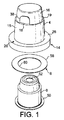
クロージャ2は、外側シェル4と、マウスピースノズル6と、ホイル環8とから組み立てられる。クロージャ2は、容器12の開いた首10に組み立てられる。
The
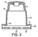
外側シェル4は、単一の要素として成形される。外側シェル4は、基部14から構成されており、該基部14は、直立する円筒の壁15を支持している。オーバーカップ16は、壁15の上部とオーバーカップ16の下側端との間の壊れやすくされた環状接合部19の中に配置された取り外し可能なタンパー要素18によって壁15に接続されている。基部14は、スカート20を有しており、該スカート20は、一連の間隔を空けられた突起22を提供され、該突起22は、容器の首10のへりにおいて、スカート20が、外側に突出するビード24の上にパチンと嵌まることを可能にする。
The
スカート20は、環状基部プレート26から垂下しており、該環状基部プレート26は、ネック10の開口部の外側部分を覆い、円筒の壁15によって囲まれた中央の円形開口部30を有する。ヒンジ構造32は、円筒の壁15をオーバーキャップ16に永久的に接続する。ヒンジ32は、壊れやすくされた接合部19の下から延び、かつ、オーバーキャップ16の側壁と合流するストリップである。ヒンジの長さは、ノズル6を妨害することなく、オーバーキャップの容易な開閉を可能にするように設計される。
The
タンパー要素18は、自由なタブ38を有する取り外し可能な楕円の部分である。取り外し可能な要素18は、下側縁36において、円筒の壁15に接合されており、上側縁34において、オーバーキャップ16に接合されている。これらの接合部は、壊れやすい領域によって提供される。ユーザがタブを前方に引っ張って、壊れやすい領域に沿った引き裂きを開始することを可能にするように、タブ38は、タンパー要素から盛り上がるようにわずかに突出している。タブ38とタンパー要素18の解放可能な部分とは、縁34または縁36における壊れやすい領域の大きさを制限することによって、基部によって保持され得る。基部14と壁15とオーバーキャップ16とを備えているシェル4は、タンパー要素18と共に1つのピースとなるように成形されるので、漏れの可能性がないように、全ての部分品がプラスチックの膜によって既に接続されているので、成形の際立った精度は、あまり重要ではない。部分品が、漏れのないように嵌められなければならない場合には、部分品は、かなり際立った精度で成形されることを必要とする。
The
垂下する円筒バルブの密閉材42は、オーバーキャップ16の内面44から突出している。
The sealing
外側シェルは、ポリエチレン(PE)か、OPP(指向性ポリプロピレン−PETのように透き通っているが、非常に安価なワーキングコピーのPPの変異体)を含むポリプロピレン(PP)か、またはPLA(ポリ乳酸)のような、農作物から生産される堆肥化可能なプラスチックのようなプラスチックから射出成形され得る。気体バリアを提供するスポーツキャップが必要とされる場合には、外側シェルはバリア材料で作られ得る。 The outer shell can be polyethylene (PE), polypropylene (PP) containing OPP (clear, like a directional polypropylene-PET, but a very cheap working copy PP variant), or PLA (polylactic acid). ) Such as compostable plastic produced from crops. If a sports cap providing a gas barrier is required, the outer shell can be made of a barrier material.
ノズル6は、外側シェル4と係合する結合部分50およびマウスピース部分を有する別個の成形物であり、該マウスピース部分は、飲用オリフィス52を画定する。ノズルは中空である。マウスピースの外側の形状は、従来技術のマウスピースのように、口と係合するのを快適にする形状にされ得る。飲用オリフィス52は、バルブの密閉材42と対応するような形状にされ、出荷時初期密閉と両密閉性との両方をクロージャに提供する。
The
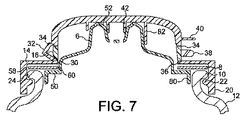
結合部分50は、突出する環状フランジ54であり、該環状フランジ54は、ノズル6の外側壁の下側縁から延びている。フランジ54は、基部プレート26に着座し、ノズルの壁は、円筒壁15の中にぴったりと嵌まっている。容器の首の中に着座するように適合されたバルブの壁(図示せず)は、フランジ54の外側縁から垂下し得る。この変形例が図7に例示されている。
The
成形物は、単純な形状であり、脆さにも関わらず、型から容易に取り除かれ得るので、ノズル6は、好適には、外側シェルに対して提案されたプラスチックまたはPETのうちの任意のもので作られる。ノズルは、ノズルの中に埋め込まれたエチレンビニルアルコール(EVOH)の層を有し得る。EVOHは、良好な気体バリアを提供する。しかしながら、ノズル6は、スポーツキャップのバリアを作り出すために、バリア材料から作られる必要はない。バリア材料で作られた外側シェル4、すなわち、バリア材料で作られた基部14と壁15とカバー16とを有することだけが不可欠である。
Because the molding is a simple shape and can be easily removed from the mold despite its brittleness, the
ホイルの環8が、クロージャ2を完成させる。ホイルの環は、各表面においてプラスチックのコーティングで被覆されたアルミニウムのホイルの薄いシートから打ち抜かれており、該プラスチックのコーティングは、プラスチックのコーティングが誘導加熱シールによって溶着されるコンポーネントのプラスチックと融和性がある。これは、従来技術において、両面誘導加熱シール(IHS)として記述されている。
A
ホイルの環8は、基部26の中に嵌まるようなサイズにされた円形の縁58を有しており、国際公開03/062061号 A(SPRECKELSEN MCGEOUGH LTD、2003年7月31日)に記述されているように、容器の側面にホイルを溶着することが所望される場合には、基部14のスカート20の内側を部分的に下って延びることも可能である。開口部60は、基部プレート26の円形開口部30の位置と対応する位置においてホイルの円形ディスクを打ち抜かれる。
The
(組み立て)
上に記述されたように、成形された外側シェル4とノズルとからクロージャを組み立てるために、ホイルの環8は、ホイルのシートから打ち抜かれ、逆さにされた外側シェル4の基部14の中に落とされる。次に、バルブ42が、飲用オリフィス52と係合して把持するまで、ノズル6が、外側シェル4の基部14の基部プレート26における開口部30を通って挿入されるか、または落とされる。次に、ホイルの環8が、フランジ50と基部プレート26との間で捕らえられ、環の外側部分が、フランジ50の外側縁とスカート20の壁との間で露出される。次に、クロージャが、誘導加熱を受け、基部プレート26に対してホイル8を密閉し、フランジ50が基部プレート26に重なる外側シェルとノズルとを溶着する。フランジ50は、薄く、犠牲となり、ホイルの縁60の上で融解するように設計され得るか、またはより厚い場合には、容器の首が、ホイル8に溶着されるように、ホイル8と接触して配置されることを可能にするために、スカート20の手前で充分に短く終端しなければならない。この設計は、第2の実施形態のように、ホイルの内側縁60の上に犠牲の壁を曲げる必要性を排除する。
(assembly)
As described above, to assemble the closure from the molded
次に、組み立てられたクロージャは、別個の誘導加熱動作によってボトルの首に溶着され得る。 The assembled closure can then be welded to the bottle neck by a separate induction heating operation.
基部24にノズル6を密閉するホイル8の環の使用が、記述されてきたが、ノズルが基部にパチント嵌まるように、コンポーネントは設計され得るということが理解される。そして、ホイル8は、ボトルまたは他の容器に基部を密閉するためにのみ必要とされる。
Although the use of an annulus of
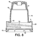
クロージャ2は、組み立てられると、完全に密閉され、瓶詰め工場に供給され、容器への組み立ての前に、殺菌が行なわれ得る。クロージャが、好適には、第2の溶着動作によって容器に対して密閉されるので、ホイル8の存在は、容器が通常のねじを切られた首の構造を必要としないということを意味するということが理解され得る。しかしながら、このクロージャは、適切に設計されたスカート20により、改変されていない容器に嵌められ得る。図8を参照されたい。
Once assembled, the
容器が、加圧された流体を意図している場合、PETボトルの壁に溶着するために、スカート20の上にホイルを提供することが必要となり得る。炭酸を含まない水を意図しているPETボトルに対しては、容器のへりにおけるビード24に対する溶着によって提供される溶着強度は、充分であり得る。
If the container is intended for pressurized fluid, it may be necessary to provide a foil on the
(第2の実施形態)
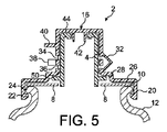
クロージャの第2の実施形態が、図5および図6に示されている(同様な参照番号は、同様な部分に対して使用されている)。この設計は、第1の実施形態と同じであるが、ノズル6の基部における結合部分50と、外側シェル4の基部と、組み立ての方法とが異なる。
(Second Embodiment)
A second embodiment of the closure is shown in FIGS. 5 and 6 (similar reference numerals are used for similar parts). This design is the same as in the first embodiment, but the
この実施形態において、オーバーキャップ16は、タンパーバンド18によって基部14に接続されている。基部14はスカート20を有しており、該スカート20は、容器10のへりにおいて外側に突出するビード24の上にパチンと嵌まるように適合されたリップ22において終端する。
In this embodiment, the
スカート20は、環状の基部プレート26から垂下しており、該環状の基部プレート26は、首10の開口部の外側部分を覆う。この実施形態において、プレート26は、内側リセス28を画定するように段を付けられている。均一の幅の環状の基部プレートが、図5に例示されているが、ノズル6を受け取る、基部プレートにおける円形の開口部30は、消費者がより容易に届くように、片側にずらされ得るということが理解される。
The
ヒンジ構造32は、オーバーキャップ16に基部14を永久的に接続する。ヒンジ32は、タンパーバンド18の下から延び、かつ、オーバーキャップ16の側壁と合流するストリップである。ヒンジの長さは、ノズル6を妨害することなく、オーバーキャップの容易な開閉を可能にするように設計される。ヒンジ32から離れるようにノズルをずらされることはまた、必要とされるヒンジの長さを減少させる。
The
タンパーバンド18は、各縁34および縁36において、オーバーキャップ16の下側の縁と基部プレート26とにそれぞれ接続されている。この接続は、縁34の少なくとも一部分と下側縁36の少なくとも一部分とに沿った壊れやすい領域によって提供される。タブ38は、ユーザがバンド18を把持し、壊れやすい領域に沿った引き裂きを開始することを可能にするように、タンパーバンドから突出する。タブ38とタンパーバンド18の解放された部分とは、縁36における壊れやすい領域の大きさを制限することによって、基部によって保持される。このタイプの保持されたタンパーバンドは、上記のHIGHLAND SPRING(登録商標)750mlのPETスポーツキャップボトルにおいて利用されている。しかしながら、その場合、基部とオーバーキャップとは、本明細書において教示されたような一体の外側シェル4としてではなく、別個の部分品として成形される。基部14とオーバーキャップ16とを備えているシェル4が、タンパー要素18と共に一体として成形されるときには、漏れの可能性がないように、全ての部分品が既にプラスチックの膜によって接続されているので、成形品の精度は非常に減少される。部分品が、この従来技術によって必要とされるように漏れのないように嵌められなければならない場合、部分品は、かなり際立った精度で成形されなければならない。
The
ピーク40が、再密封を容易にするようにオーバーキャップ16に提供される。
A
ノズル6は、先の実施形態において記述されているようなものであるが、結合部分50が、突出している環状フランジ54である点で異なっており、該突出している環状フランジ54は、フランジ54の下に短い犠牲の壁56を残すように、下側の縁のすぐ上のノズル6の外壁から延びている。フランジ54は、基部プレート26におけるリセス28に着座し、ノズルの外壁は、開口部30の中にぴったりと嵌まる。
The
ホイルの環8は、先のようにクロージャ2を完成させる。ノズルがずらされる場合には、ホイルの環は、その周囲において均一な幅ではないということが理解される。
The
(第2の実施形態の組み立て)
上で記述されたように、成形された外側シェル4とノズルとからクロージャを組み立てるために、バルブ42が、飲用オリフィスと係合して把持するまで、ノズル6は、外側シェル4の基部14の基部プレート26における開口部30を通って下から挿入される。ホイルの環8は、ホイルシートから打ち抜かれ、犠牲の壁56とスカート20との間に画定されるリセスの中に落とされ、それによりフランジ54の縁と外側シェルとの間の間隙を覆う。そうしなければ、該外側シェルは、殺菌することが困難である。次に、ホイル8は、クロージャに溶着される。リセス内にホイルを配置するツールがまた、ホイル開口部の縁60を覆って犠牲の壁56を折り重ねる。そうしなければホイル開口部の縁60は、アルミニウムが露出される。ホイルが加熱されたときに、犠牲の壁56のプラスチックが、露出されたアルミニウムの縁の上に融解することにより、国際公開2005/092728 A(SPRECKELSEN MCGEOUGH LTD、2005年10月6日)に記述されているように、露出されたアルミニウムの縁を埋め込む。
(Assembly of the second embodiment)
As described above, for assembling the closure from the molded
第1の実施形態と関連して、クロージャは、ホイル8の露出された部分を利用する別個の誘導加熱密閉動作によって、容器に対して密閉を行われ得る。
In connection with the first embodiment, the closure can be sealed to the container by a separate induction heating sealing operation utilizing the exposed portion of the
(第3の実施形態)
クロージャの第3の実施形態が図7に示されている(同様な参照番号は、同様な部分に対して使用される)。この設計は、第1の実施形態と同様であるが、ノズル6が基部14の中で中心に置かれておらず、ずらされており、新たな密閉バルブ構造が、結合部分50に示されているという点で異なる。代替のノズル外形が示されており、オーバーキャップは、ノズル6の外面と係合するようにバルブの密閉材42と同心の第2の外側のバルブの密閉材82を有する。この実施形態は、第1の実施形態と同様に組み立てられる。
(Third embodiment)
A third embodiment of the closure is shown in FIG. 7 (similar reference numerals are used for similar parts). This design is similar to the first embodiment, but the
結合部分50は、垂下するバルブの壁80において終端し、該垂下するバルブの壁80は、容器12の開いた首10の中に押し嵌まるように設計されている。これは、クロージャが、炭酸飲料のような加圧された内容物を含む容器に使用されるときに、特に有利である。この状況において、圧力は、バルブの壁80を首に対して押しやり、適切な位置にクロージャを保持するように働く。
The
外側シェル4が一体に成形されることを可能にするために、基部14における開口部30は、カバー16の内径よりも小さい直径を有し得ない。この単純な一体の成形が先行させられる場合には、外側シェルは、上の段落0013において記述されたEVIAN(登録商標)ACTIONのクロージャと同じ方法で成形され得るということが理解される。
In order to allow the
(第4の実施形態)
図8のクロージャは、28mm、30mm、33mm、35mm、38mmおよび43mmまたは45mmのような一般的なサイズの任意のものにおける標準規格の予備成形PCOの首の仕上げにおいて従来の方法で嵌めるように設計されているという点においてのみ、第1の実施形態と異なる。スカート20は、標準規格の首における外部のねじ筋と協働する内部のねじ筋70を提供されている。スカート20の下側縁は、壊れやすいブリッジ74によっていたずら防止ストリップ72に接続され得る。クロージャのこの実施形態は、既存のボトルの改変を全く必要とすることなく、使用され得る。
(Fourth embodiment)
The closure of FIG. 8 is designed to fit in a conventional manner in the finishing of standard preformed PCO necks in any of the common sizes such as 28 mm, 30 mm, 33 mm, 35 mm, 38 mm and 43 mm or 45 mm. It is different from the first embodiment only in that it is done. The
(変化形)
別個のヒンジ32が記述されてきたが、オーバーキャップと基部との間の永久的な接続としてタンパーバンド18の一部分を維持することによって、ヒンジを作成することが可能である。
(Variable)
Although a
タンパー要素18はまた、省かれ得、オーバーキャップ16の下側縁が、壊れやすい領域によって基部に接合され得る。次に、ピーク40は、ユーザがピーク40を使用して、オーバーキャップ16の引き剥がしを開始し、ヒンジ手段として働くように基部に接続されたオーバーキャップの縁の一部分だけを残すことを可能にするように、充分に強固であることを必要とする。
The
クロージャが、一体の気体バリアを有するボトルに使用される場合には、バルブ42の範囲内にホイルの密閉材を含むことが望ましいことがあり得る。これは、GB 2412368 A(SPRECKELSEN MCGEOUGH LTD、2005年9月28日.2005)に記述された手法によって達成され得る。
If the closure is used with a bottle having an integral gas barrier, it may be desirable to include a foil seal within the
Claims (11)
容器の首(10)に嵌められるように適合された基部と、取り外し可能なタンパー要素(18)によって基部(14)に接続されるオーバーキャップ(16)とを画定する外側シェル(4)と、
該外側シェル(4)の内部に組み立てられる、飲用オリフィス(52)を画定する別個のノズル(6)と、
誘導加熱シール用ホイル(8)と
を備えており、該ホイル(8)は、該基部(14)と該ノズル(6)とに溶着される環であり、該オーバーキャップは、該飲用オリフィス(52)と係合し、かつ、密閉するために、内面から垂下しているバルブシール(42)を有するということを特徴とする、クロージャ(2)。 A closure (2) for the container (12),
An outer shell (4) defining a base adapted to fit on the neck (10) of the container and an overcap (16) connected to the base (14) by a removable tamper element (18);
A separate nozzle (6) defining a drinking orifice (52) assembled within the outer shell (4);
A foil (8) for induction heating sealing, the foil (8) is a ring welded to the base (14) and the nozzle (6), and the overcap is the drinking orifice ( 52) Closure (2), characterized in that it has a valve seal (42) depending from the inner surface for engaging and sealing.
Applications Claiming Priority (2)
| Application Number | Priority Date | Filing Date | Title |
|---|---|---|---|
| GB0526014A GB2433496B (en) | 2005-12-22 | 2005-12-22 | Tamper evident drinking fitment |
| PCT/GB2006/050464 WO2007072076A1 (en) | 2005-12-22 | 2006-12-19 | Drinking fitment |
Publications (2)
| Publication Number | Publication Date |
|---|---|
| JP2009520656A true JP2009520656A (en) | 2009-05-28 |
| JP2009520656A5 JP2009520656A5 (en) | 2011-01-13 |
Family
ID=35840876
Family Applications (1)
| Application Number | Title | Priority Date | Filing Date |
|---|---|---|---|
| JP2008546641A Withdrawn JP2009520656A (en) | 2005-12-22 | 2006-12-19 | Drinking equipment |
Country Status (16)
| Country | Link |
|---|---|
| US (1) | US20090308832A1 (en) |
| EP (1) | EP1966059B1 (en) |
| JP (1) | JP2009520656A (en) |
| CN (1) | CN101331070A (en) |
| AT (1) | ATE458678T1 (en) |
| AU (1) | AU2006327966A1 (en) |
| CA (1) | CA2633614A1 (en) |
| DE (1) | DE602006012545D1 (en) |
| ES (1) | ES2339597T3 (en) |
| GB (1) | GB2433496B (en) |
| NZ (1) | NZ569099A (en) |
| PL (1) | PL1966059T3 (en) |
| PT (1) | PT1966059E (en) |
| RU (1) | RU2008129891A (en) |
| WO (1) | WO2007072076A1 (en) |
| ZA (1) | ZA200805339B (en) |
Cited By (4)
| Publication number | Priority date | Publication date | Assignee | Title |
|---|---|---|---|---|
| JP2014210613A (en) * | 2013-04-22 | 2014-11-13 | サーモス株式会社 | Beverage container |
| CN106415216A (en) * | 2014-03-28 | 2017-02-15 | 霍尼韦尔国际公司 | Threaded coupling device with nozzle for GWR measurements in non-metallic tanks |
| JP2020040733A (en) * | 2019-11-25 | 2020-03-19 | サーモス株式会社 | Mounting structure and mounting method of member |
| JP2020142835A (en) * | 2019-03-07 | 2020-09-10 | 日本山村硝子株式会社 | cap |
Families Citing this family (12)
| Publication number | Priority date | Publication date | Assignee | Title |
|---|---|---|---|---|
| GB2447661A (en) * | 2007-03-20 | 2008-09-24 | Brian Antony Rush | Dispensing cap for a bottle |
| JP5200266B2 (en) * | 2007-04-11 | 2013-06-05 | 東洋製罐株式会社 | Container heat sealing method and apparatus |
| US20100102021A1 (en) * | 2008-10-23 | 2010-04-29 | Obrist Closures Switzerland Gmbh | Closure |
| KR101160270B1 (en) * | 2009-11-12 | 2012-06-27 | 포항공과대학교 산학협력단 | Liquid container |
| GB201408598D0 (en) * | 2014-05-14 | 2014-06-25 | Obrist Closures Switzerland | Improvements in or relating to container closures |
| USD757543S1 (en) * | 2015-01-08 | 2016-05-31 | Runway Blue, Llc | Spout for a container |
| USD778725S1 (en) * | 2015-01-08 | 2017-02-14 | Runway Blue, Llc | Spout for a container |
| US9663277B2 (en) * | 2015-09-24 | 2017-05-30 | Aptargroup, Inc. | Container closure |
| JP7094672B2 (en) * | 2017-08-31 | 2022-07-04 | 大和製罐株式会社 | Hinge caps and containers |
| US11066215B2 (en) * | 2018-12-03 | 2021-07-20 | Ink Projects Llc | Tattoo bottle with secure lid |
| USD949692S1 (en) | 2018-12-03 | 2022-04-26 | Ink Projects Llc | Tattoo ink bottle cap |
| US11214414B2 (en) * | 2019-09-18 | 2022-01-04 | Silgan White Cap LLC | Tamper evident flip cap |
Family Cites Families (22)
| Publication number | Priority date | Publication date | Assignee | Title |
|---|---|---|---|---|
| US3363811A (en) * | 1965-06-28 | 1968-01-16 | R C Can Co | Container with frangible seal for extrudable materials |
| US4043475A (en) * | 1976-10-15 | 1977-08-23 | Glyndon Plastics Limited | Caps and containers |
| US4537318A (en) * | 1984-05-07 | 1985-08-27 | Sunbeam Plastics Corp. | Dispensing closure lock and seal |
| US4917267A (en) * | 1986-11-12 | 1990-04-17 | Laverdure Roland J A | Self-closing valve with tamper evident lip seal tab for liquids, pastes or solids |
| JPH01267157A (en) * | 1988-04-07 | 1989-10-25 | Showa Denko Kk | Can-like container lid and production therefor |
| US5348184A (en) * | 1991-03-05 | 1994-09-20 | Portola Packaging, Inc. | Unitary tamper-evident fitment and closure assembly |
| DE29508151U1 (en) * | 1995-05-17 | 1995-08-17 | Georg Menshen Gmbh & Co Kg | Slit valve for closing containers |
| US6334555B1 (en) * | 2000-05-25 | 2002-01-01 | Seaquist Closures Foreign, Inc. | Fitment and resealable dispensing closure assembly for high-pressure sealing and bi-modal dispensing |
| ES2248140T3 (en) * | 2000-11-02 | 2006-03-16 | Bapco Closures Research Limited | SEALING UNIT WATERPROOF SEALABLE TO GASES. |
| AU2002359098A1 (en) * | 2001-12-18 | 2003-06-30 | Alto Packaging Limited | Sipper cap with reciprocally movable nozzle |
| GB2406851B (en) * | 2002-01-10 | 2005-09-28 | Closures & Packaging Serv Ltd | A self-venting sports type closure |
| NZ534253A (en) * | 2002-01-25 | 2007-11-30 | Bapco Closures Res Ltd | Container closures |
| US20050116382A1 (en) * | 2002-07-12 | 2005-06-02 | Philippe Nusbaum | Closure device comprising a hinged cap moulded in the closed position |
| AU2004265129B2 (en) * | 2003-08-11 | 2010-02-25 | Bap Tech Pty Ltd | Opening devices for foil closures |
| NO323158B1 (en) * | 2003-09-16 | 2007-01-08 | Smartseal As | Device at a valve for a drinking vessel |
| GB2408040B (en) * | 2003-11-14 | 2005-10-12 | Spreckelsen Mcgeough Ltd | Fitments |
| ITMI20040663A1 (en) * | 2004-04-01 | 2004-07-01 | Guglielmo Ferrari | CLOSING CAP TO SCREW ON A SCREW NECK OF A CONTAINER |
| GB2426509B (en) * | 2004-07-27 | 2007-06-13 | Bapco Closures Res Ltd | Resealable closures |
| DE102004045511B3 (en) * | 2004-09-20 | 2005-10-13 | Seaquist-Löffler Kunststoffwerk Gmbh | Dispensing closure for liquid containers, in particular beverage containers |
| DE102005034178A1 (en) * | 2005-07-21 | 2006-07-27 | Adelholzener Alpenquellen Gmbh | Device for storing a liquid enriched with carbon dioxide and/or oxygen comprises a sealing body having a projection and a closure having a toothed element which interacts with the projection in a detachable manner |
| US7537141B1 (en) * | 2005-07-26 | 2009-05-26 | Rexam Closure Systems Inc. | Dispensing closure and package |
| US7731066B2 (en) * | 2005-08-04 | 2010-06-08 | Colgate-Palmolive Company | Closure |
-
2005
- 2005-12-22 GB GB0526014A patent/GB2433496B/en not_active Expired - Fee Related
-
2006
- 2006-12-19 NZ NZ569099A patent/NZ569099A/en unknown
- 2006-12-19 AT AT06820689T patent/ATE458678T1/en not_active IP Right Cessation
- 2006-12-19 EP EP06820689A patent/EP1966059B1/en not_active Not-in-force
- 2006-12-19 PL PL06820689T patent/PL1966059T3/en unknown
- 2006-12-19 ES ES06820689T patent/ES2339597T3/en active Active
- 2006-12-19 US US12/158,660 patent/US20090308832A1/en not_active Abandoned
- 2006-12-19 CN CNA2006800477160A patent/CN101331070A/en active Pending
- 2006-12-19 JP JP2008546641A patent/JP2009520656A/en not_active Withdrawn
- 2006-12-19 AU AU2006327966A patent/AU2006327966A1/en not_active Abandoned
- 2006-12-19 RU RU2008129891/12A patent/RU2008129891A/en not_active Application Discontinuation
- 2006-12-19 PT PT06820689T patent/PT1966059E/en unknown
- 2006-12-19 CA CA002633614A patent/CA2633614A1/en not_active Abandoned
- 2006-12-19 DE DE602006012545T patent/DE602006012545D1/en active Active
- 2006-12-19 WO PCT/GB2006/050464 patent/WO2007072076A1/en active Application Filing
- 2006-12-19 ZA ZA200805339A patent/ZA200805339B/en unknown
Cited By (6)
| Publication number | Priority date | Publication date | Assignee | Title |
|---|---|---|---|---|
| JP2014210613A (en) * | 2013-04-22 | 2014-11-13 | サーモス株式会社 | Beverage container |
| KR101576734B1 (en) | 2013-04-22 | 2015-12-10 | 서어모스 케이.케이. | Beverage container |
| CN106415216A (en) * | 2014-03-28 | 2017-02-15 | 霍尼韦尔国际公司 | Threaded coupling device with nozzle for GWR measurements in non-metallic tanks |
| CN106415216B (en) * | 2014-03-28 | 2020-11-10 | 霍尼韦尔国际公司 | Threaded coupling with nozzle for GWR measurements in non-metallic tanks |
| JP2020142835A (en) * | 2019-03-07 | 2020-09-10 | 日本山村硝子株式会社 | cap |
| JP2020040733A (en) * | 2019-11-25 | 2020-03-19 | サーモス株式会社 | Mounting structure and mounting method of member |
Also Published As
| Publication number | Publication date |
|---|---|
| PL1966059T3 (en) | 2010-07-30 |
| RU2008129891A (en) | 2010-01-27 |
| AU2006327966A1 (en) | 2007-06-28 |
| ZA200805339B (en) | 2009-08-26 |
| US20090308832A1 (en) | 2009-12-17 |
| CN101331070A (en) | 2008-12-24 |
| DE602006012545D1 (en) | 2010-04-08 |
| PT1966059E (en) | 2010-03-22 |
| EP1966059A1 (en) | 2008-09-10 |
| CA2633614A1 (en) | 2007-06-28 |
| GB0526014D0 (en) | 2006-02-01 |
| NZ569099A (en) | 2010-02-26 |
| ES2339597T3 (en) | 2010-05-21 |
| EP1966059B1 (en) | 2010-02-24 |
| ATE458678T1 (en) | 2010-03-15 |
| WO2007072076A1 (en) | 2007-06-28 |
| GB2433496B (en) | 2007-11-21 |
| GB2433496A (en) | 2007-06-27 |
Similar Documents
| Publication | Publication Date | Title |
|---|---|---|
| JP2009520656A (en) | Drinking equipment | |
| EP1547934B1 (en) | Closure with frangible membrane | |
| US5755360A (en) | Multi-material, multi-shot, injection molded dispensing closure having a removable seal | |
| CA2510805C (en) | Tamper evident closure assemblies | |
| US6439429B1 (en) | Tamper-evident closure and spout fitment for a pouch | |
| US5967376A (en) | Insert molded tamper evident pouring spout | |
| US20020104843A1 (en) | One-piece tamper-evident closure system with a resealable, hinged lid | |
| US20090188887A1 (en) | Closures and containers in combination therewith | |
| EP1086024A1 (en) | Closure with dual hinge means | |
| KR20000053018A (en) | One-piece molded flip cap closure | |
| US20100140268A1 (en) | Dispensing closure with removable membrane | |
| GB2426509A (en) | Resealable closure | |
| US5855288A (en) | Resealable closure | |
| US4196819A (en) | Reducer-carrying cap | |
| CN101389544B (en) | Pre-foiled closures | |
| US5950876A (en) | Insert molded tamper evident pouring spout | |
| MX2008008173A (en) | Drinking fitment | |
| JP4736542B2 (en) | Pull ring type spout tool | |
| JP2007069979A (en) | Container with cap holder | |
| JP2004533974A (en) | Tamper-evident seals and spout fittings for bag-shaped containers | |
| MXPA00000256A (en) | A resealable closure | |
| NZ555687A (en) | Tamper evident closure assemblies | |
| NZ540797A (en) | Tamper evident closure assemblies |
Legal Events
| Date | Code | Title | Description |
|---|---|---|---|
| A521 | Request for written amendment filed |
Free format text: JAPANESE INTERMEDIATE CODE: A523 Effective date: 20091027 |
|
| A621 | Written request for application examination |
Free format text: JAPANESE INTERMEDIATE CODE: A621 Effective date: 20091027 |
|
| A072 | Dismissal of procedure [no reply to invitation to correct request for examination] |
Free format text: JAPANESE INTERMEDIATE CODE: A073 Effective date: 20110315 |
|
| A300 | Application deemed to be withdrawn because no request for examination was validly filed |
Free format text: JAPANESE INTERMEDIATE CODE: A300 Effective date: 20110405 |