JP2009518981A - System and method for error resilience and random access in video communication systems - Google Patents
System and method for error resilience and random access in video communication systems Download PDFInfo
- Publication number
- JP2009518981A JP2009518981A JP2008544667A JP2008544667A JP2009518981A JP 2009518981 A JP2009518981 A JP 2009518981A JP 2008544667 A JP2008544667 A JP 2008544667A JP 2008544667 A JP2008544667 A JP 2008544667A JP 2009518981 A JP2009518981 A JP 2009518981A
- Authority
- JP
- Japan
- Prior art keywords
- picture
- frame
- svcs
- layer
- endpoint
- Prior art date
- Legal status (The legal status is an assumption and is not a legal conclusion. Google has not performed a legal analysis and makes no representation as to the accuracy of the status listed.)
- Pending
Links
Images


Classifications
-
- H—ELECTRICITY
- H04—ELECTRIC COMMUNICATION TECHNIQUE
- H04N—PICTORIAL COMMUNICATION, e.g. TELEVISION
- H04N19/00—Methods or arrangements for coding, decoding, compressing or decompressing digital video signals
- H04N19/50—Methods or arrangements for coding, decoding, compressing or decompressing digital video signals using predictive coding
- H04N19/503—Methods or arrangements for coding, decoding, compressing or decompressing digital video signals using predictive coding involving temporal prediction
- H04N19/51—Motion estimation or motion compensation
-
- H—ELECTRICITY
- H04—ELECTRIC COMMUNICATION TECHNIQUE
- H04N—PICTORIAL COMMUNICATION, e.g. TELEVISION
- H04N21/00—Selective content distribution, e.g. interactive television or video on demand [VOD]
- H04N21/20—Servers specifically adapted for the distribution of content, e.g. VOD servers; Operations thereof
- H04N21/25—Management operations performed by the server for facilitating the content distribution or administrating data related to end-users or client devices, e.g. end-user or client device authentication, learning user preferences for recommending movies
- H04N21/266—Channel or content management, e.g. generation and management of keys and entitlement messages in a conditional access system, merging a VOD unicast channel into a multicast channel
- H04N21/2662—Controlling the complexity of the video stream, e.g. by scaling the resolution or bitrate of the video stream based on the client capabilities
-
- H—ELECTRICITY
- H04—ELECTRIC COMMUNICATION TECHNIQUE
- H04L—TRANSMISSION OF DIGITAL INFORMATION, e.g. TELEGRAPHIC COMMUNICATION
- H04L1/00—Arrangements for detecting or preventing errors in the information received
- H04L1/12—Arrangements for detecting or preventing errors in the information received by using return channel
- H04L1/16—Arrangements for detecting or preventing errors in the information received by using return channel in which the return channel carries supervisory signals, e.g. repetition request signals
- H04L1/1607—Details of the supervisory signal
-
- H—ELECTRICITY
- H04—ELECTRIC COMMUNICATION TECHNIQUE
- H04L—TRANSMISSION OF DIGITAL INFORMATION, e.g. TELEGRAPHIC COMMUNICATION
- H04L1/00—Arrangements for detecting or preventing errors in the information received
- H04L1/12—Arrangements for detecting or preventing errors in the information received by using return channel
- H04L1/16—Arrangements for detecting or preventing errors in the information received by using return channel in which the return channel carries supervisory signals, e.g. repetition request signals
- H04L1/18—Automatic repetition systems, e.g. Van Duuren systems
- H04L1/1829—Arrangements specially adapted for the receiver end
- H04L1/1848—Time-out mechanisms
-
- H—ELECTRICITY
- H04—ELECTRIC COMMUNICATION TECHNIQUE
- H04L—TRANSMISSION OF DIGITAL INFORMATION, e.g. TELEGRAPHIC COMMUNICATION
- H04L65/00—Network arrangements, protocols or services for supporting real-time applications in data packet communication
- H04L65/60—Network streaming of media packets
- H04L65/75—Media network packet handling
- H04L65/752—Media network packet handling adapting media to network capabilities
-
- H—ELECTRICITY
- H04—ELECTRIC COMMUNICATION TECHNIQUE
- H04L—TRANSMISSION OF DIGITAL INFORMATION, e.g. TELEGRAPHIC COMMUNICATION
- H04L65/00—Network arrangements, protocols or services for supporting real-time applications in data packet communication
- H04L65/60—Network streaming of media packets
- H04L65/75—Media network packet handling
- H04L65/756—Media network packet handling adapting media to device capabilities
-
- H—ELECTRICITY
- H04—ELECTRIC COMMUNICATION TECHNIQUE
- H04L—TRANSMISSION OF DIGITAL INFORMATION, e.g. TELEGRAPHIC COMMUNICATION
- H04L65/00—Network arrangements, protocols or services for supporting real-time applications in data packet communication
- H04L65/80—Responding to QoS
-
- H—ELECTRICITY
- H04—ELECTRIC COMMUNICATION TECHNIQUE
- H04N—PICTORIAL COMMUNICATION, e.g. TELEVISION
- H04N19/00—Methods or arrangements for coding, decoding, compressing or decompressing digital video signals
- H04N19/10—Methods or arrangements for coding, decoding, compressing or decompressing digital video signals using adaptive coding
- H04N19/102—Methods or arrangements for coding, decoding, compressing or decompressing digital video signals using adaptive coding characterised by the element, parameter or selection affected or controlled by the adaptive coding
- H04N19/132—Sampling, masking or truncation of coding units, e.g. adaptive resampling, frame skipping, frame interpolation or high-frequency transform coefficient masking
-
- H—ELECTRICITY
- H04—ELECTRIC COMMUNICATION TECHNIQUE
- H04N—PICTORIAL COMMUNICATION, e.g. TELEVISION
- H04N19/00—Methods or arrangements for coding, decoding, compressing or decompressing digital video signals
- H04N19/10—Methods or arrangements for coding, decoding, compressing or decompressing digital video signals using adaptive coding
- H04N19/134—Methods or arrangements for coding, decoding, compressing or decompressing digital video signals using adaptive coding characterised by the element, parameter or criterion affecting or controlling the adaptive coding
- H04N19/164—Feedback from the receiver or from the transmission channel
- H04N19/166—Feedback from the receiver or from the transmission channel concerning the amount of transmission errors, e.g. bit error rate [BER]
-
- H—ELECTRICITY
- H04—ELECTRIC COMMUNICATION TECHNIQUE
- H04N—PICTORIAL COMMUNICATION, e.g. TELEVISION
- H04N19/00—Methods or arrangements for coding, decoding, compressing or decompressing digital video signals
- H04N19/10—Methods or arrangements for coding, decoding, compressing or decompressing digital video signals using adaptive coding
- H04N19/169—Methods or arrangements for coding, decoding, compressing or decompressing digital video signals using adaptive coding characterised by the coding unit, i.e. the structural portion or semantic portion of the video signal being the object or the subject of the adaptive coding
- H04N19/17—Methods or arrangements for coding, decoding, compressing or decompressing digital video signals using adaptive coding characterised by the coding unit, i.e. the structural portion or semantic portion of the video signal being the object or the subject of the adaptive coding the unit being an image region, e.g. an object
- H04N19/172—Methods or arrangements for coding, decoding, compressing or decompressing digital video signals using adaptive coding characterised by the coding unit, i.e. the structural portion or semantic portion of the video signal being the object or the subject of the adaptive coding the unit being an image region, e.g. an object the region being a picture, frame or field
-
- H—ELECTRICITY
- H04—ELECTRIC COMMUNICATION TECHNIQUE
- H04N—PICTORIAL COMMUNICATION, e.g. TELEVISION
- H04N19/00—Methods or arrangements for coding, decoding, compressing or decompressing digital video signals
- H04N19/10—Methods or arrangements for coding, decoding, compressing or decompressing digital video signals using adaptive coding
- H04N19/169—Methods or arrangements for coding, decoding, compressing or decompressing digital video signals using adaptive coding characterised by the coding unit, i.e. the structural portion or semantic portion of the video signal being the object or the subject of the adaptive coding
- H04N19/17—Methods or arrangements for coding, decoding, compressing or decompressing digital video signals using adaptive coding characterised by the coding unit, i.e. the structural portion or semantic portion of the video signal being the object or the subject of the adaptive coding the unit being an image region, e.g. an object
- H04N19/176—Methods or arrangements for coding, decoding, compressing or decompressing digital video signals using adaptive coding characterised by the coding unit, i.e. the structural portion or semantic portion of the video signal being the object or the subject of the adaptive coding the unit being an image region, e.g. an object the region being a block, e.g. a macroblock
-
- H—ELECTRICITY
- H04—ELECTRIC COMMUNICATION TECHNIQUE
- H04N—PICTORIAL COMMUNICATION, e.g. TELEVISION
- H04N19/00—Methods or arrangements for coding, decoding, compressing or decompressing digital video signals
- H04N19/30—Methods or arrangements for coding, decoding, compressing or decompressing digital video signals using hierarchical techniques, e.g. scalability
- H04N19/31—Methods or arrangements for coding, decoding, compressing or decompressing digital video signals using hierarchical techniques, e.g. scalability in the temporal domain
-
- H—ELECTRICITY
- H04—ELECTRIC COMMUNICATION TECHNIQUE
- H04N—PICTORIAL COMMUNICATION, e.g. TELEVISION
- H04N19/00—Methods or arrangements for coding, decoding, compressing or decompressing digital video signals
- H04N19/30—Methods or arrangements for coding, decoding, compressing or decompressing digital video signals using hierarchical techniques, e.g. scalability
- H04N19/37—Methods or arrangements for coding, decoding, compressing or decompressing digital video signals using hierarchical techniques, e.g. scalability with arrangements for assigning different transmission priorities to video input data or to video coded data
-
- H—ELECTRICITY
- H04—ELECTRIC COMMUNICATION TECHNIQUE
- H04N—PICTORIAL COMMUNICATION, e.g. TELEVISION
- H04N19/00—Methods or arrangements for coding, decoding, compressing or decompressing digital video signals
- H04N19/46—Embedding additional information in the video signal during the compression process
- H04N19/463—Embedding additional information in the video signal during the compression process by compressing encoding parameters before transmission
-
- H—ELECTRICITY
- H04—ELECTRIC COMMUNICATION TECHNIQUE
- H04N—PICTORIAL COMMUNICATION, e.g. TELEVISION
- H04N19/00—Methods or arrangements for coding, decoding, compressing or decompressing digital video signals
- H04N19/50—Methods or arrangements for coding, decoding, compressing or decompressing digital video signals using predictive coding
- H04N19/503—Methods or arrangements for coding, decoding, compressing or decompressing digital video signals using predictive coding involving temporal prediction
- H04N19/51—Motion estimation or motion compensation
- H04N19/573—Motion compensation with multiple frame prediction using two or more reference frames in a given prediction direction
-
- H—ELECTRICITY
- H04—ELECTRIC COMMUNICATION TECHNIQUE
- H04N—PICTORIAL COMMUNICATION, e.g. TELEVISION
- H04N19/00—Methods or arrangements for coding, decoding, compressing or decompressing digital video signals
- H04N19/50—Methods or arrangements for coding, decoding, compressing or decompressing digital video signals using predictive coding
- H04N19/503—Methods or arrangements for coding, decoding, compressing or decompressing digital video signals using predictive coding involving temporal prediction
- H04N19/51—Motion estimation or motion compensation
- H04N19/577—Motion compensation with bidirectional frame interpolation, i.e. using B-pictures
-
- H—ELECTRICITY
- H04—ELECTRIC COMMUNICATION TECHNIQUE
- H04N—PICTORIAL COMMUNICATION, e.g. TELEVISION
- H04N19/00—Methods or arrangements for coding, decoding, compressing or decompressing digital video signals
- H04N19/50—Methods or arrangements for coding, decoding, compressing or decompressing digital video signals using predictive coding
- H04N19/503—Methods or arrangements for coding, decoding, compressing or decompressing digital video signals using predictive coding involving temporal prediction
- H04N19/51—Motion estimation or motion compensation
- H04N19/58—Motion compensation with long-term prediction, i.e. the reference frame for a current frame not being the temporally closest one
-
- H—ELECTRICITY
- H04—ELECTRIC COMMUNICATION TECHNIQUE
- H04N—PICTORIAL COMMUNICATION, e.g. TELEVISION
- H04N19/00—Methods or arrangements for coding, decoding, compressing or decompressing digital video signals
- H04N19/50—Methods or arrangements for coding, decoding, compressing or decompressing digital video signals using predictive coding
- H04N19/587—Methods or arrangements for coding, decoding, compressing or decompressing digital video signals using predictive coding involving temporal sub-sampling or interpolation, e.g. decimation or subsequent interpolation of pictures in a video sequence
-
- H—ELECTRICITY
- H04—ELECTRIC COMMUNICATION TECHNIQUE
- H04N—PICTORIAL COMMUNICATION, e.g. TELEVISION
- H04N19/00—Methods or arrangements for coding, decoding, compressing or decompressing digital video signals
- H04N19/60—Methods or arrangements for coding, decoding, compressing or decompressing digital video signals using transform coding
- H04N19/61—Methods or arrangements for coding, decoding, compressing or decompressing digital video signals using transform coding in combination with predictive coding
-
- H—ELECTRICITY
- H04—ELECTRIC COMMUNICATION TECHNIQUE
- H04N—PICTORIAL COMMUNICATION, e.g. TELEVISION
- H04N19/00—Methods or arrangements for coding, decoding, compressing or decompressing digital video signals
- H04N19/65—Methods or arrangements for coding, decoding, compressing or decompressing digital video signals using error resilience
- H04N19/66—Methods or arrangements for coding, decoding, compressing or decompressing digital video signals using error resilience involving data partitioning, i.e. separation of data into packets or partitions according to importance
-
- H—ELECTRICITY
- H04—ELECTRIC COMMUNICATION TECHNIQUE
- H04N—PICTORIAL COMMUNICATION, e.g. TELEVISION
- H04N19/00—Methods or arrangements for coding, decoding, compressing or decompressing digital video signals
- H04N19/65—Methods or arrangements for coding, decoding, compressing or decompressing digital video signals using error resilience
- H04N19/67—Methods or arrangements for coding, decoding, compressing or decompressing digital video signals using error resilience involving unequal error protection [UEP], i.e. providing protection according to the importance of the data
-
- H—ELECTRICITY
- H04—ELECTRIC COMMUNICATION TECHNIQUE
- H04N—PICTORIAL COMMUNICATION, e.g. TELEVISION
- H04N19/00—Methods or arrangements for coding, decoding, compressing or decompressing digital video signals
- H04N19/70—Methods or arrangements for coding, decoding, compressing or decompressing digital video signals characterised by syntax aspects related to video coding, e.g. related to compression standards
-
- H—ELECTRICITY
- H04—ELECTRIC COMMUNICATION TECHNIQUE
- H04N—PICTORIAL COMMUNICATION, e.g. TELEVISION
- H04N19/00—Methods or arrangements for coding, decoding, compressing or decompressing digital video signals
- H04N19/85—Methods or arrangements for coding, decoding, compressing or decompressing digital video signals using pre-processing or post-processing specially adapted for video compression
- H04N19/89—Methods or arrangements for coding, decoding, compressing or decompressing digital video signals using pre-processing or post-processing specially adapted for video compression involving methods or arrangements for detection of transmission errors at the decoder
-
- H—ELECTRICITY
- H04—ELECTRIC COMMUNICATION TECHNIQUE
- H04N—PICTORIAL COMMUNICATION, e.g. TELEVISION
- H04N21/00—Selective content distribution, e.g. interactive television or video on demand [VOD]
- H04N21/40—Client devices specifically adapted for the reception of or interaction with content, e.g. set-top-box [STB]; Operations thereof
- H04N21/45—Management operations performed by the client for facilitating the reception of or the interaction with the content or administrating data related to the end-user or to the client device itself, e.g. learning user preferences for recommending movies, resolving scheduling conflicts
- H04N21/462—Content or additional data management, e.g. creating a master electronic program guide from data received from the Internet and a Head-end, controlling the complexity of a video stream by scaling the resolution or bit-rate based on the client capabilities
- H04N21/4621—Controlling the complexity of the content stream or additional data, e.g. lowering the resolution or bit-rate of the video stream for a mobile client with a small screen
-
- H—ELECTRICITY
- H04—ELECTRIC COMMUNICATION TECHNIQUE
- H04N—PICTORIAL COMMUNICATION, e.g. TELEVISION
- H04N21/00—Selective content distribution, e.g. interactive television or video on demand [VOD]
- H04N21/60—Network structure or processes for video distribution between server and client or between remote clients; Control signalling between clients, server and network components; Transmission of management data between server and client, e.g. sending from server to client commands for recording incoming content stream; Communication details between server and client
- H04N21/63—Control signaling related to video distribution between client, server and network components; Network processes for video distribution between server and clients or between remote clients, e.g. transmitting basic layer and enhancement layers over different transmission paths, setting up a peer-to-peer communication via Internet between remote STB's; Communication protocols; Addressing
- H04N21/631—Multimode Transmission, e.g. transmitting basic layers and enhancement layers of the content over different transmission paths or transmitting with different error corrections, different keys or with different transmission protocols
-
- H—ELECTRICITY
- H04—ELECTRIC COMMUNICATION TECHNIQUE
- H04N—PICTORIAL COMMUNICATION, e.g. TELEVISION
- H04N21/00—Selective content distribution, e.g. interactive television or video on demand [VOD]
- H04N21/60—Network structure or processes for video distribution between server and client or between remote clients; Control signalling between clients, server and network components; Transmission of management data between server and client, e.g. sending from server to client commands for recording incoming content stream; Communication details between server and client
- H04N21/63—Control signaling related to video distribution between client, server and network components; Network processes for video distribution between server and clients or between remote clients, e.g. transmitting basic layer and enhancement layers over different transmission paths, setting up a peer-to-peer communication via Internet between remote STB's; Communication protocols; Addressing
- H04N21/637—Control signals issued by the client directed to the server or network components
- H04N21/6375—Control signals issued by the client directed to the server or network components for requesting retransmission, e.g. of data packets lost or corrupted during transmission from server
-
- H—ELECTRICITY
- H04—ELECTRIC COMMUNICATION TECHNIQUE
- H04N—PICTORIAL COMMUNICATION, e.g. TELEVISION
- H04N21/00—Selective content distribution, e.g. interactive television or video on demand [VOD]
- H04N21/60—Network structure or processes for video distribution between server and client or between remote clients; Control signalling between clients, server and network components; Transmission of management data between server and client, e.g. sending from server to client commands for recording incoming content stream; Communication details between server and client
- H04N21/65—Transmission of management data between client and server
- H04N21/658—Transmission by the client directed to the server
- H04N21/6583—Acknowledgement
-
- H—ELECTRICITY
- H04—ELECTRIC COMMUNICATION TECHNIQUE
- H04L—TRANSMISSION OF DIGITAL INFORMATION, e.g. TELEGRAPHIC COMMUNICATION
- H04L1/00—Arrangements for detecting or preventing errors in the information received
- H04L1/12—Arrangements for detecting or preventing errors in the information received by using return channel
- H04L1/16—Arrangements for detecting or preventing errors in the information received by using return channel in which the return channel carries supervisory signals, e.g. repetition request signals
- H04L1/18—Automatic repetition systems, e.g. Van Duuren systems
- H04L1/1812—Hybrid protocols; Hybrid automatic repeat request [HARQ]
Abstract
ビデオ通信システムでのエラー回復力のある伝送およびランダムアクセスのためのシステムおよび方法が提供される。ビデオ通信システムは、ビデオ通信システムで使用することのできる時間スケーラビリティを有する単層、スケーラブルビデオ、またはサイマルキャストビデオコーディングに基づく。ビデオ信号伝送での1組のビデオフレームまたはピクチャが、セキュアまたは高信頼性リンクを使用して、または再送信技法により、受信側への配信の信頼性を高め、またはそれを保証するように指定される。確実に配信されるビデオフレームが、エラー発生後の送信されたビデオ信号との受信側の再同期のため、およびランダムアクセスのための基準ピクチャとして使用される。
【選択図】図1Systems and methods for error resilient transmission and random access in video communication systems are provided. Video communication systems are based on single layer, scalable video, or simulcast video coding with temporal scalability that can be used in video communication systems. Specifies that a set of video frames or pictures in a video signal transmission will increase or guarantee the reliability of delivery to the receiver using a secure or reliable link or through retransmission techniques Is done. A reliably delivered video frame is used for reference resynchronization with the transmitted video signal after the error occurs and as a reference picture for random access.
[Selection] Figure 1
Description
本願は、2005年12月8日出願の米国仮特許出願第60/748,437号、2006年3月3日出願の米国仮特許出願第60/778,760号、2006年3月29日出願の米国仮特許出願第60/787,043号、2006年3月29日出願の米国仮特許出願第60/787,031号、2006年10月16日出願の米国仮特許出願第60/829,618号、および米国仮特許出願第60/862,510号の特典を主張するものである。上述の優先権出願のすべては、参照によりその全体が本明細書に組み込まれる。 This application includes US Provisional Patent Application No. 60 / 748,437, filed December 8, 2005, US Provisional Patent Application No. 60 / 778,760, filed March 3, 2006, and US Provisional Patent, filed March 29, 2006. Application No. 60 / 787,043, U.S. Provisional Patent Application No. 60 / 787,031, filed Mar. 29, 2006, U.S. Provisional Patent Application No. 60 / 829,618, filed Oct. 16, 2006, and U.S. Provisional Patent Application No. 60 Claims the benefits of / 862,510. All of the above priority applications are incorporated herein by reference in their entirety.
本発明はビデオデータ通信システムに関する。詳細には、本発明は、テレビ会議アプリケーション(適用例)でのエラー回復力およびランダムアクセス機能を提供する技法に関する。 The present invention relates to a video data communication system. In particular, the present invention relates to techniques for providing error resiliency and random access functionality in video conferencing applications (applications).
パケットベースの現代の通信ネットワーク(例えばインターネットプロトコル(IP)に基づくネットワーク)を介して送信側と受信側の間で高品質デジタルビデオ通信を実現することは、少なくともそのようなネットワーク上のデータ移送が通常はベストエフォート式に実施されるために、技術的に難しいことである。現代の通信ネットワークでの伝送エラーは一般に、初期の通信システムに特徴的であったビットエラーではなく、パケット紛失として現れる。パケット紛失はしばしば、物理層エラーの結果ではなく、中継ルータでの輻輳(混雑)の結果である。 Realizing high-quality digital video communication between the sender and receiver over a packet-based modern communication network (e.g., a network based on the Internet Protocol (IP)) means that data transport over such a network is Usually, it is technically difficult because it is implemented in a best effort manner. Transmission errors in modern communication networks generally appear as lost packets rather than bit errors that were characteristic of early communication systems. Packet loss is often the result of congestion at the relay router, not the result of a physical layer error.
デジタルビデオ通信システムで伝送エラーが生じたとき、受信側がエラーから迅速に回復し、着信ビデオ信号のエラーのない表示に戻ることができることを保証することが重要である。しかし、典型的なデジタルビデオ通信システムでは、帯域幅を温存するために着信データが大きく圧縮されることによって受信側の堅牢性が低下する。さらに、通信システムで利用されるビデオ圧縮技法(例えば、最新のコーデックITU-T H.264およびH.263またはISO MPEG-2およびMPEG-4コーデック)が、順次ビデオパケット間またはフレーム間の非常に強い時間的依存関係を生み出す可能性がある。具体的には、動き補償予測コーデックの使用(例えば、PフレームまたはBフレームの使用を含む)は、表示されるフレームが過去のフレームに依存するというフレーム依存関係の連鎖を生み出す。依存関係の連鎖は、ビデオシーケンスの最初まで延在する可能性がある。依存関係の連鎖の結果として、所与のパケットの紛失が、受信側でのいくつかの後続のパケットの復号化に影響を及ぼす可能性がある。所与のパケットの紛失によるエラー伝播が「イントラ」(I)リフレッシュポイント、または時間的予測をまったく使用しないフレームでのみ終了する。 When a transmission error occurs in a digital video communication system, it is important to ensure that the receiver can quickly recover from the error and return to an error-free display of the incoming video signal. However, in a typical digital video communication system, incoming data is greatly compressed to conserve bandwidth, reducing the robustness of the receiving side. In addition, video compression techniques utilized in communication systems (e.g., the latest codecs ITU-T H.264 and H.263 or ISO MPEG-2 and MPEG-4 codecs) can be very useful between video packets or frames sequentially. It can create strong temporal dependencies. Specifically, the use of motion compensated prediction codecs (eg, including the use of P or B frames) creates a chain of frame dependencies in which the displayed frame depends on past frames. The dependency chain can extend to the beginning of the video sequence. As a result of the dependency chain, the loss of a given packet can affect the decoding of some subsequent packets at the receiver. Error propagation due to loss of a given packet ends only with "intra" (I) refresh points, or frames that do not use any temporal prediction.
デジタルビデオ通信システムでのエラー回復力は、伝送される信号において少なくともいくつかのレベルの冗長性を有することを必要とする。しかし、この要件は、伝送される信号の冗長性をなくし、または最小限に抑えるように試みるビデオ圧縮技法の目的と相入れない。 Error resiliency in digital video communication systems requires having at least some level of redundancy in the transmitted signal. However, this requirement is incompatible with the purpose of video compression techniques that attempt to eliminate or minimize the redundancy of the transmitted signal.
差別化サービスを提供するネットワーク(例えばDiffServ IPベースのネットワーク、専用回線を介するプライベートネットワークなど)上では、ビデオデータ通信アプリケーションが、ネットワーク機能を利用して、ビデオ信号データの一部またはすべてを受信側に無損失またはほぼ無損失で配信することができる。しかし、差別化サービスを提供しない任意のベストエフォートネットワーク(インターネットなど)では、データ通信アプリケーションは、エラー回復力を達成するためにそれ自体の機能に依拠しなければならない。テキストまたは英数字データ通信で有用な周知の技法(例えば伝送制御プロトコル-TCP)は、ヒューマンインターフェース要件から生じる低エンドツーエンド遅延の制約が追加されるビデオまたはオーディオの通信には適していない。例えば、テキストまたは英数データ移送でのエラー回復力のためにTCP技法を使用することができる。TCPは、数秒の遅延を伴う場合であっても、すべてのデータが受信されたという確認まで、データを再送信し続ける。しかし、TCPは、限界のないエンドツーエンド遅延が参加者にとっては受け入れられないものとなるので、ライブまたは対話式のテレビ会議アプリケーションでのビデオデータ移送には不適切である。 On networks that provide differentiated services (for example, DiffServ IP-based networks, private networks over leased lines, etc.), video data communication applications use network functions to receive some or all of the video signal data. Can be delivered lossless or almost lossless. However, in any best effort network that does not provide differentiated services (such as the Internet), data communication applications must rely on their own capabilities to achieve error resiliency. Well-known techniques useful in text or alphanumeric data communication (eg, Transmission Control Protocol-TCP) are not suitable for video or audio communication, which adds low end-to-end delay constraints resulting from human interface requirements. For example, TCP techniques can be used for error resiliency in text or alphanumeric data transport. TCP continues to retransmit data until confirmation that all data has been received, even with a delay of a few seconds. However, TCP is unsuitable for video data transport in live or interactive video conferencing applications, as endless end-to-end delays are unacceptable for participants.
関連する問題は、ランダムアクセスの問題である。受信側がビデオ信号の既存の伝送に参加すると仮定する。典型的な例は、テレビ会議に参加するユーザ、またはブロードキャストに同調するユーザである。そのようなユーザは、ユーザが復号化を開始することができ、ユーザがエンコーダと同期する着信ビットストリーム中のポイントを見つけなければならない。しかし、そのようなランダムアクセスポイントを設けることは、圧縮効率にかなりの影響を及ぼす。ランダムアクセスポイントでは任意のエラー伝播が終了するので、定義上、そのポイントはエラー回復力機能であることに留意されたい(すなわち、そのポイントはエラー回復ポイントである)。したがって、特定のコーディング方式によって提供されるランダムアクセスサポートが良好であるほど、その特定のコーディング方式が実現するエラー回復が高速になる。その逆は常に真であるわけではなく、エラー回復力技法が対処するように設計されたエラーの持続時間および範囲について行われた仮定に依存する。エラー回復力について、エラーが生じた時に受信側である状態情報が利用可能であると仮定することができる。 A related problem is that of random access. Assume that the receiver participates in an existing transmission of the video signal. A typical example is a user attending a video conference or a user tuned to a broadcast. Such a user must find a point in the incoming bitstream where the user can start decoding and where the user synchronizes with the encoder. However, providing such a random access point has a significant impact on compression efficiency. Note that any error propagation ends at a random access point, so by definition that point is an error resiliency function (ie, that point is an error recovery point). Therefore, the better the random access support provided by a particular coding scheme, the faster the error recovery achieved by that particular coding scheme. The converse is not always true and depends on assumptions made about the duration and extent of errors that the error resiliency technique is designed to address. For error resilience, it can be assumed that the status information at the receiving end is available when an error occurs.
ビデオ通信システムでのエラー回復力の一態様は、圧縮効率にかなりの影響を及ぼすランダムアクセス(例えば、受信側がビデオ信号の既存の伝送に参加するとき)に関する。ランダムアクセスの例は、例えば、テレビ会議に参加するユーザ、またはブロードキャストに同調するユーザである。そのようなユーザは、復号化を開始し、エンコーダと同期するために、着信ビットストリーム中のポイントを見つけなければならなくなる。ランダムアクセスポイントでは任意のエラー伝播が終了するので、そのポイントは実質上、エラー回復力機能である(またはエラー回復ポイントである)。したがって、良好なランダムアクセスサポートを提供する特定のコーディング方式は一般に、より高速なエラー回復を実現するエラー回復力技法を有する。しかし、その逆は、エラー回復力技法が対処するように設計されたエラーの持続時間および範囲について行われた仮定に依存する。エラー回復力技法は、エラーが生じた時に受信側である状態情報が利用可能であると仮定することがある。そのような場合、エラー回復力技法は良好なランダムアクセスサポートを保証しない。 One aspect of error resilience in video communication systems relates to random access that significantly affects compression efficiency (eg, when a receiver participates in an existing transmission of a video signal). An example of random access is, for example, a user participating in a video conference or a user tuned to a broadcast. Such a user will have to find a point in the incoming bitstream in order to start decoding and synchronize with the encoder. Since any error propagation ends at a random access point, that point is essentially an error resiliency function (or an error recovery point). Thus, certain coding schemes that provide good random access support generally have error resiliency techniques that provide faster error recovery. The converse, however, depends on assumptions made about the duration and range of errors that the error resiliency technique is designed to address. Error resiliency techniques may assume that status information is available at the receiver when an error occurs. In such cases, error resiliency techniques do not guarantee good random access support.
デジタルテレビジョンシステム(デジタルケーブルTVまたは衛星TV)用のMPEG-2ビデオコーデックでは、ストリームへの高速な切換えを可能にするために、Iピクチャが周期的な間隔(通常は0.5秒)で使用される。しかしIピクチャは、PまたはBピクチャよりもかなり大きく(通常は3〜6倍)、したがって、低帯域幅および/または低遅延応用例では特に回避すべきものである。 In MPEG-2 video codecs for digital television systems (digital cable TV or satellite TV), I-pictures are used at periodic intervals (usually 0.5 seconds) to allow fast switching to streams. The However, I-pictures are much larger (usually 3-6 times) than P- or B-pictures and should therefore be avoided especially in low bandwidth and / or low delay applications.
テレビ会議などの対話式応用例では、イントラ更新の要求という概念が、エラー回復力のためにしばしば使用される。動作の際に、更新は、デコーダの同期を可能にするイントラピクチャ伝送を求める受信側から送信側への要求を含む。この動作の帯域幅オーバヘッドはかなりのものである。さらに、パケットエラーが生じるときにもこのオーバヘッドを受ける。パケット紛失が輻輳によって引き起こされる場合、イントラピクチャの使用は輻輳問題を悪化させるだけである。 In interactive applications such as video conferencing, the concept of requesting an intra-update is often used for error resiliency. In operation, the update includes a request from the receiving side to the transmitting side for intra-picture transmissions that allow the decoder to synchronize. The bandwidth overhead of this operation is considerable. Furthermore, this overhead is also incurred when a packet error occurs. If packet loss is caused by congestion, the use of intra pictures only exacerbates the congestion problem.
IDCT実装(例えばH.261標準)での不整合によって引き起こされるドリフトを軽減するために過去に使用された、エラー堅牢性のための別の従来の技法は、各マクロブロックイントラモードを周期的にコーディングすることである。H.261標準は、マクロブロックが132回送信されるごとに強制的イントラコーディングを必要とする。 Another conventional technique for error robustness, used in the past to mitigate drift caused by inconsistencies in IDCT implementations (e.g., H.261 standard), is to make each macroblock intra mode periodic Is to code. The H.261 standard requires forced intracoding every time a macroblock is transmitted 132 times.
コーディング効率は、所与のフレームでイントラとして強制的にコーディングされるマクロブロックのパーセンテージが増加すると共に減少する。逆に、このパーセンテージが低いとき、パケット紛失から回復するための時間が増大する。強制的イントラコーディングプロセスは、動き関連のドリフトを回避するために余分の注意を必要とし、それがさらにエンコーダの性能を制限する。ある動きベクトル値が最も効果的である場合であってもそれを回避しなければならないからである。 Coding efficiency decreases as the percentage of macroblocks that are forced to be coded as intra in a given frame increases. Conversely, when this percentage is low, the time to recover from packet loss increases. The forced intracoding process requires extra care to avoid motion-related drift, which further limits the performance of the encoder. This is because even if a certain motion vector value is most effective, it must be avoided.
従来型単層コーデックに加えて、階層化コーディングまたはスケーラブルコーディングが、マルチメディアデータ符号化での周知の技法である。スケーラブルコーディングは、帯域幅効率の良い方式で所与の媒体を集合的に表す2つ以上の「スケーリングされた」ビットストリームを生成するのに使用される。スケーラビリティをいくつかの異なる次元、すなわち時間、空間、および品質として提供することができる(SNR「信号対雑音比」スケーラビリティとも呼ばれる)。例えば、ビデオ信号を、CIF解像度およびQCIF解像度で、フレームレート7.5、15、および30フレーム/秒(fps)で異なる層としてスケーラブルにコーディングすることができる。コーデックの構造に応じて、コーデックビットストリームから空間解像度とフレームレートの任意の組合せを得ることができる。異なる層に対応するビットを別々のビットストリームとして送信することができ(すなわち層当たり1ストリーム)、またはそれらを互いに1つまたは複数のビットストリームとして多重化することができる。本明細書では説明の都合上、様々な層が単一のビットストリームとして多重化および送信される場合であっても、所与の層に対応するコード化ビットをその層のビットストリームと呼ぶことがある。スケーラビリティ機能を提供するように特に設計されたコーデックは、例えばMPEG-2(ISO/IEC13818-2、ITU-T H.262とも呼ばれる)、現在開発されているSVC(ITU-T H.264 Annex GまたはMPEG-4 Part 10 SVCとも呼ばれる)を含む。ビデオ通信用に特に設計されたスケーラブルコーディング技法が本願の譲受人に譲渡された国際特許出願PCT/US06/028365、「SYSTEM AND METHOD FOR SCALABLE AND LOW-DELAY VIDEOCONFERENCING USING SCALABLE VIDEO CODING」に記載されている。スケーラブルとなるように特に設計されていないコーデックであっても、時間次元ではスケーラビリティ特性を示すことができることに留意されたい。例えば、DVD環境およびデジタルTV環境で使用される非スケーラブルコーデックであるMPEG-2 Main Profileコーデックを考慮する。さらに、コーデックが3
0fpsで動作し、IBBPBBPBBPBBPBBのGOP構造(周期N=15フレーム)が使用されると仮定する。Bピクチャの順次除去と、その後に続くPピクチャの除去により、30fps(すべてのピクチャタイプが含まれる)、10(IおよびPのみ)、および2fps(Iのみ)の合計3つの時間解像度を導出することが可能である。PピクチャのコーディングがBピクチャに依拠せず、同様にIピクチャのコーディングが他のPピクチャまたはBピクチャに依拠しないようにMPEG-2 Main Profileコーデックが設計されるので、順次除去プロセスの結果、復号化可能ビットストリームが得られる。以下では、時間スケーラビリティ機能を有する単層コーデックが、スケーラブルビデオコーディングの特別なケースであるとみなされ、したがって明示的な指示がない限り、スケーラブルビデオコーディングという用語に含まれる。
In addition to conventional single layer codecs, layered coding or scalable coding is a well-known technique in multimedia data coding. Scalable coding is used to generate two or more “scaled” bitstreams that collectively represent a given medium in a bandwidth efficient manner. Scalability can be provided in several different dimensions: time, space, and quality (also called SNR “signal to noise ratio” scalability). For example, video signals can be scalable coded as different layers at frame rates 7.5, 15, and 30 frames per second (fps) with CIF and QCIF resolution. Depending on the structure of the codec, any combination of spatial resolution and frame rate can be obtained from the codec bitstream. Bits corresponding to different layers can be transmitted as separate bitstreams (ie, one stream per layer) or they can be multiplexed together as one or more bitstreams. For purposes of explanation herein, the coded bits corresponding to a given layer will be referred to as that layer's bitstream, even if the various layers are multiplexed and transmitted as a single bitstream. There is. Codecs that are specifically designed to provide scalability functions are, for example, MPEG-2 (ISO / IEC13818-2, also called ITU-T H.262), currently developed SVC (ITU-T H.264 Annex G Or MPEG-4 Part 10 SVC). A scalable coding technique specifically designed for video communication is described in International Patent Application PCT / US06 / 028365, "SYSTEM AND METHOD FOR SCALABLE AND LOW-DELAY VIDEOCONFERENCING USING SCALABLE VIDEO CODING", assigned to the assignee of the present application. . Note that even codecs that are not specifically designed to be scalable can exhibit scalability characteristics in the time dimension. For example, consider the MPEG-2 Main Profile codec, which is a non-scalable codec used in DVD and digital TV environments. In addition, the codec is 3
Assume that it operates at 0 fps and uses the GOP structure of IBBPBBPBBPBBPBB (period N = 15 frames). Sequential removal of B pictures followed by removal of P pictures leads to a total of three temporal resolutions of 30 fps (including all picture types), 10 (I and P only), and 2 fps (I only) It is possible. Since the MPEG-2 Main Profile codec is designed so that the coding of P pictures does not depend on B pictures, and similarly the coding of I pictures does not depend on other P pictures or B pictures, decoding as a result of the sequential removal process Can be obtained. In the following, a single layer codec with temporal scalability capability is considered to be a special case of scalable video coding and is therefore included in the term scalable video coding unless there is an explicit indication.
スケーラブルコーデックは通常、構成ビットストリームのうちの1つ(「ベース層」と呼ばれる)がある基本的品質で元の媒体を回復する際に不可欠である、ピラミッド状のビットストリーム構造を有する。ベース層と共に1つまたは複数の残りのビットストリーム(「拡張層」と呼ばれる)を使用することは、回復される媒体の品質を向上させる。拡張層でのデータ紛失は許容可能であるが、ベース層でのデータ紛失は、著しいひずみを引き起こす可能性があり、または回復される媒体が完全に失われる可能性がある。 A scalable codec typically has a pyramidal bitstream structure that is essential in recovering the original medium with a basic quality of one of the constituent bitstreams (called the “base layer”). Using one or more remaining bitstreams (referred to as “enhancement layer”) with the base layer improves the quality of the recovered media. While loss of data at the enhancement layer is acceptable, loss of data at the base layer can cause significant distortion, or the recovered media can be completely lost.
スケーラブルコーデックは、エラー回復力およびランダムアクセスについて単層コーデックによって課されるのと同様の問題を提起する。しかし、スケーラブルコーデックのコーディング構造は、単層ビデオコーデックには存在しない固有の特性を有する。さらに、単層コーディングとは異なり、スケーラブルコーディングは、あるスケーラビリティ層から別のスケーラビリティ層への切換え(例えば、CIF解像度とQCIF解像度との間の切換え)を含むことができる。 Scalable codecs pose the same problems imposed by single layer codecs for error resiliency and random access. However, the coding structure of the scalable codec has unique characteristics that do not exist in the single layer video codec. Further, unlike single layer coding, scalable coding can include switching from one scalability layer to another (eg, switching between CIF resolution and QCIF resolution).
サイマルキャスティングは、スケーラブルビデオコーディングよりは複雑ではないが、スケーラブルビデオコーディングの利点の一部を有する、テレビ会議向けのコーディング解決策である。サイマルキャスティングでは、ソースの2つの異なるバージョンが符号化され(例えば2つの異なる空間解像度で)、送信される。各バージョンは、その復号化が他のバージョンの受信に依存しない点で独立である。スケーラブルコーディングおよび単層コーディングと同様に、サイマルキャスティングは、同様のランダムアクセスおよび堅牢性の問題を提起する。以下では、サイマルキャスティングがスケーラブルコーディングの特別なケース(層間予測が実施されない)とみなされ、両者は、明示的な指示がない限り、単にスケーラブルビデオコーディング技法と呼ばれる。 Simulcasting is a coding solution for video conferencing that is less complex than scalable video coding, but has some of the advantages of scalable video coding. In simulcasting, two different versions of a source are encoded (eg, at two different spatial resolutions) and transmitted. Each version is independent in that its decoding does not depend on reception of other versions. Similar to scalable and single layer coding, simulcasting raises similar random access and robustness issues. In the following, simulcasting is considered a special case of scalable coding (interlayer prediction is not performed), and both are simply referred to as scalable video coding techniques unless explicitly indicated.
ビデオ通信システムでのエラー回復力およびコード化ビットストリームへのランダムアクセスのための機能を向上するために考慮すべき点がここで与えられる。エンドツーエンド遅延およびシステムで使用される帯域幅に対する影響が最小限であるエラー回復力およびランダムアクセス技法を開発することに注意が向けられる。望ましいエラー回復力およびランダムアクセス技法は、スケーラブルコーディングと単層ビデオコーディングのどちらにも適用可能となる。 Points to consider here are given to improve the ability for error resilience and random access to coded bitstreams in video communication systems. Attention is directed to developing error resiliency and random access techniques that have minimal impact on end-to-end delay and bandwidth used in the system. Desirable error resilience and random access techniques can be applied to both scalable coding and single layer video coding.
本発明は、単層コーディングならびにスケーラブルビデオコーディングに基づくビデオ通信システムでのエラー回復力を向上させ、ランダムアクセス機能を提供するシステムおよび方法を提供する。 The present invention provides systems and methods for improving error resiliency and providing random access functionality in video communication systems based on single layer coding as well as scalable video coding.
第1の例示的実施形態では、本発明は、エンドツーエンド遅延を増大させることなく、コード化ビデオ信号の最下層または単一時間層のすべてまたは各部分を確実に送信し、次いでそれを使用してパケット紛失から回復する機構を提供する。RTPを介する伝送のため、ならびにH.264 Annex G(SVC)NALユニットを使用するときのために特定の技法が提供される。 In a first exemplary embodiment, the present invention reliably transmits and then uses all or each part of the bottom layer or single time layer of the coded video signal without increasing end-to-end delay. Provides a mechanism to recover from packet loss. Specific techniques are provided for transmission over RTP, as well as when using H.264 Annex G (SVC) NAL units.
第2の例示的実施形態では、本発明は、サーバベースのイントラフレームを使用して符号化ビデオ信号の最下層または単一時間層を確実に送信し、次いでそれを使用して、他の受信側に悪影響を及ぼすことなくパケット紛失から特定の受信側を回復する機構を提供する。 In a second exemplary embodiment, the present invention uses server-based intra frames to reliably transmit the lowest or single time layer of the encoded video signal, which is then used to receive other receptions. A mechanism is provided to recover a particular receiver from packet loss without adversely affecting the receiver.
第3の例示的実施形態では、本発明は、注意深く編成された方式でイントラマクロブロックコーディングを使用することにより、単層ビデオコーディングおよびスケーラブルビデオコーディングでパケット紛失から回復することが可能となる機構を提供する。 In a third exemplary embodiment, the present invention provides a mechanism that allows recovery from packet loss in single layer video coding and scalable video coding by using intra macroblock coding in a carefully organized manner. provide.
第4の例示的実施形態では、本発明は、ピクチャ基準フレームならびにイントラマクロブロックの割振りを最適に選択するために、1つまたは複数の受信側からフィードバックを収集および集約する機構を提供する。 In a fourth exemplary embodiment, the present invention provides a mechanism for collecting and aggregating feedback from one or more receivers to optimally select picture reference frames as well as intra macroblock allocation.
第5の例示的実施形態では、本発明は、低解像度空間層からの情報を使用することによって高解像度空間スケーラブル層の紛失パケットから回復する機構を提供する。 In a fifth exemplary embodiment, the present invention provides a mechanism to recover from lost packets in the high resolution spatial scalable layer by using information from the low resolution spatial layer.
さらに、第6の例示的実施形態では、本発明は、ほとんど遅延なく、または遅延なしで、低空間解像度または低品質解像度から高空間解像度または品質解像度に切り換える機構を提供する。 Further, in a sixth exemplary embodiment, the present invention provides a mechanism for switching from a low spatial resolution or low quality resolution to a high spatial resolution or quality resolution with little or no delay.
レートひずみ最適化量子化器(rate-distortion optimized quantizer)ならびに動きモードおよびベクトル選択と結合されると、こうした実施形態は、単独または組合せとして、堅牢性が高く、帯域幅オーバヘッドの小さい、極めて効率的なビデオ通信システムの構築を可能にする。 When combined with a rate-distortion optimized quantizer and motion mode and vector selection, these embodiments, either alone or in combination, are robust and have low bandwidth overhead and are extremely efficient. It is possible to construct a simple video communication system.
本明細書の説明は、こうした技法を使用して所与のビデオストリームへのランダムアクセスをどのように実装するか、ならびに低層の完全な復号化を必要としない前記低層からの情報を使用して、受信側が効果的に高層に関する高空間解像度データを構築することのできる機構を説明する。本発明は、スケーラブルビデオコーディング技法の特殊な特性を利用して、エンドツーエンド遅延および帯域幅に対する影響を最小限に抑える。本発明は、エンドツーエンド要件が厳格であり(最大200msecエンドツーエンド)、パケット紛失レートが厳しい(すなわち、長いバースト以外では低平均パケット紛失レート)である可能性のある、IPネットワークを介するテレビ会議などの通信応用例で特に有用である。 The description herein uses such techniques to implement random access to a given video stream, as well as using information from the lower layer that does not require full decoding of the lower layer. A mechanism by which the receiving side can effectively construct high spatial resolution data for high layers will be described. The present invention takes advantage of the special characteristics of scalable video coding techniques to minimize the impact on end-to-end delay and bandwidth. The present invention provides a television over IP network with strict end-to-end requirements (up to 200 msec end-to-end) and potentially strict packet loss rates (i.e., low average packet loss rate except for long bursts). This is particularly useful in communication applications such as conferences.
本発明の技法は、ピクチャコーディング構造および移送モードを適切に選択したときに、非常にわずかな帯域幅オーバヘッドでほぼ瞬間的な層切換えを可能にする。 The technique of the present invention allows near instantaneous layer switching with very little bandwidth overhead when the picture coding structure and transport mode are properly selected.
別段の記述がない限り、各図全体を通して、図示される実施形態の同様の機能要素、構成要素、または部分を示すのに同一の参照番号および参照符号を使用する。さらに、これから各図を参照しながら本発明を説明するが、例示的実施形態に関連してそのように行われる。 Unless otherwise noted, the same reference numbers and reference numerals are used throughout the figures to indicate similar functional elements, components, or parts of the illustrated embodiments. Furthermore, while the present invention will now be described with reference to the figures, it is done so in connection with the exemplary embodiments.
本発明は、ビデオ通信システムでのエラー回復力のある伝送およびランダムアクセスのためのシステムおよび方法を提供する。機構は、ビデオ通信システムで使用することのできるスケーラブルビデオコーディング技法、ならびに時間スケーラビリティを有する単層およびサイマルキャストビデオコーディングと互換である。 The present invention provides systems and methods for error resilient transmission and random access in video communication systems. The mechanism is compatible with scalable video coding techniques that can be used in video communication systems, as well as single layer and simulcast video coding with temporal scalability.
このシステムおよび方法は、受信側への配信の信頼性を高め、またはそれを保証するために、ビデオ信号伝送で1組のビデオフレームまたはピクチャを指定することを含む。指定した1組のビデオフレームの信頼性の高い配信は、セキュアリンクまたは高信頼性リンクを使用することによって、または再送信技法によって実施することができる。確実に配信されたビデオフレームが、エラー発生後の送信されたビデオ信号との受信側の再同期のため、またはランダムアクセスのための基準ピクチャとして使用される。 The system and method include specifying a set of video frames or pictures in a video signal transmission to increase or guarantee the reliability of delivery to the receiver. Reliable delivery of a specified set of video frames can be performed by using a secure link or a reliable link, or by a retransmission technique. The reliably delivered video frame is used as a reference picture for receiver resynchronization with the transmitted video signal after the error occurs or for random access.
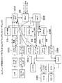
好ましい実施形態では、例示的ビデオ通信システムは、パケットベースのネットワークを介して運用されるマルチポイントテレビ会議システム10でよい(例えば図1を参照)。マルチポイントテレビ会議システムは、ネットワークを介するエンドポイント(例えばユーザ1-kおよび1-m)間のスケーラブル多層または単層ビデオ通信を仲介するために、任意選択のブリッジ120aおよび120b(例えばマルチポイント制御ユニット(MCU)またはスケーラブルビデオ通信サーバ(SVCS))を含むことができる。例示的ビデオ通信システムの動作は、任意選択のブリッジ120aおよび120bの使用を伴う、または伴わないポイントツーポイント接続について同じであり、そのポイントツーポイント接続にとって有利である。
In a preferred embodiment, the exemplary video communication system may be a
スケーラブルビデオコーディング技法およびスケーラブルビデオコーディングに基づくテレビ会議システムの詳細な説明が、本願の譲受人に譲渡された国際特許出願PCT/US06/28365、「SYSTEM AND METHOD FOR SCALABLE AND LOW-DELAY VIDEOCONFERENCING USING SCALABLE VIDEO CODING」およびPCT/US06/28366、「SYSTEM AND METHOD FOR A CONFERENCE SERVER ARCHITECTURE FOR LOW DELAY AND DISTRIBUTED CONFERENCING APPLICATIONS」で与えられている。さらに、スケーラブルビデオコーディング技法およびスケーラブルビデオコーディングに基づくテレビ会議システムの説明が、2005年12月22日出願の米国仮特許出願第60,753,343号、「COMPOSITING SCALABLE VIDEO CONFERENCE SERVER」で与えられている。上述の国際特許出願および米国仮特許出願のすべては、参照によりその全体が本明細書に組み込まれる。 A detailed description of scalable video coding techniques and videoconferencing systems based on scalable video coding can be found in the international patent application PCT / US06 / 28365, “SYSTEM AND METHOD FOR SCALABLE AND LOW-DELAY VIDEOCONFERENCING USING SCALABLE VIDEO, assigned to the assignee of the present application. CODING "and PCT / US06 / 28366," SYSTEM AND METHOD FOR A CONFERENCE SERVER ARCHITECTURE FOR LOW DELAY AND DISTRIBUTED CONFERENCING APPLICATIONS ". In addition, a description of scalable video coding techniques and videoconferencing systems based on scalable video coding is given in US Provisional Patent Application No. 60,753,343, “COMPOSITING SCALABLE VIDEO CONFERENCE SERVER” filed on December 22, 2005. All of the aforementioned international patent applications and US provisional patent applications are incorporated herein by reference in their entirety.
図1は、テレビ会議システム10の一般的構造を示す。テレビ会議システム10は、LAN1および2ならびにサーバ120aおよび120bを通じてネットワーク100を介してリンクされる複数のエンドユーザ端末(例えばユーザ1-kおよびユーザ1-m)を含む。サーバは、従来型MCUでよく、あるいはスケーラブルビデオコーディングサーバ(SVCS)またはコンポジッティングスケーラブルビデオコーディングサーバ(CSVCS)でよい。後者のサーバは、従来型MCUと同じ目的を有するが、複雑さが著しく低減され、機能が改善されている(例えば国際特許出願PCT/US06/28366および米国仮特許出願60/753,343号、2005年12月22日を参照)。本明細書の説明では、「サーバ」という用語をSVCSまたはCSVCSを総称的に指すのに使用することがある。
FIG. 1 shows a general structure of the
図2は、単層コーディングに基づくテレビ会議システム(例えばシステム10)と共に使用されるように設計されるエンドユーザ端末140のアーキテクチャを示す。同様に、図3は、多層コーディングに基づくテレビ会議システム(例えばシステム10)と共に使用されるように設計されるエンドユーザ端末140のアーキテクチャを示す。端末140は、ヒューマンインターフェース入出力装置(例えばカメラ210A、マイクロフォン210B、ビデオディスプレイ250C、スピーカ250D)と、入出力信号マルチプレクサユニットおよびデマルチプレクサユニット(例えばパケットMUX220AおよびパケットDMUX220B)とに結合された1つまたは複数のネットワークインターフェースコントローラカード(NIC)230とを含む。NIC230は、イーサネット(登録商標)LANアダプタなどの標準ハードウェア構成要素、または任意の他の適切なネットワークインターフェース装置、またはそれらの組合せでよい。
FIG. 2 shows the architecture of an
カメラ210Aおよびマイクロフォン210Bは、他の会議参加者に送信するために参加者ビデオ信号および参加者オーディオ信号をそれぞれ取り込むように設計される。逆に、ビデオディスプレイ250Cおよびスピーカ250Dは、他の参加者から受信したビデオ信号およびオーディオ信号をそれぞれ表示および再生するように設計される。ビデオディスプレイ250Cは、参加者/端末140自体のビデオを任意選択で表示するように構成することもできる。カメラ210A出力およびマイクロフォン210B出力は、それぞれアナログ-デジタル変換器210Eおよび210Fを介してビデオエンコーダ210Gおよびオーディオエンコーダ210Hに結合される。ビデオエンコーダ210Gおよびオーディオエンコーダ210Hは、電子通信ネットワークを介する信号の伝送のために必要な帯域幅を削減するために、入力ビデオデジタル信号および入力オーディオデジタル信号を圧縮するように設計される。入力ビデオ信号は、ライブビデオ信号でよく、または事前記録され、格納されたビデオ信号でよい。エンコーダは、信号の伝送に必要な帯域幅を最小限に抑えるためにローカルデジタル信号を圧縮する。
本発明の例示的実施形態では、当技術分野で周知の任意の適切な技法(例えばG.711、G.729、G.729EV、MPEG-1など)を使用してオーディオ信号を符号化することができる。本発明の好ましい実施形態では、スケーラブルオーディオコーデックG.729EVがオーディオエンコーダ210Gで使用されてオーディオ信号が符号化される。オーディオエンコーダ210Gの出力はマルチプレクサMUX220Aに送られ、NIC230を通じてネットワーク100を介して伝送される。
In an exemplary embodiment of the invention, the audio signal is encoded using any suitable technique known in the art (e.g., G.711, G.729, G.729EV, MPEG-1, etc.). Can do. In the preferred embodiment of the present invention, the scalable audio codec G.729EV is used in the
パケットMUX220Aは、RTPプロトコルを使用して従来型多重化を実施することができる。パケットMUX220Aは、ネットワーク100で提供することのできる任意の関連サービス品質(QoS)処理を実施することができる。端末140からのデータの各ストリームが、それ自体の仮想チャネル、またはIP用語では「ポート番号」で送信される。
The
図3は、スケーラブルまたはサイマルキャストビデオコーディングが使用されるテレビ会議システムと共に使用されるように構成されるエンドユーザ端末140を示す。この場合、ビデオエンコーダ210Gは複数の出力を有する。図3は、例えば、「ベース」および「拡張」と符号が付けられた2層出力を示す。端末140の出力(すなわち単層出力(図2)または複数層出力(図3))は、LRP処理モジュール270Aを介してパケットMUX220Aに接続される。LRP処理モジュール270A(およびモジュール270B)は、特殊なタイプのフレーム(例えば図12および13の「R」フレーム)と、ビデオシーケンスヘッダデータなどの信頼性の高い伝送を必要とする任意の他の情報の伝送を処理することにより、エラー回復力のある通信(「エラー回復力LRPオペレーション」)向けに設計される。ビデオエンコーダ210Gが複数の拡張層出力を生成する場合、図3に示されるのと同様に、それぞれをLRP処理モジュール270Aに接続することができる。同様に、この場合、LRP処理モジュール270Bを介してビデオデコーダ230Aに対して追加の拡張層が設けられる。あるいは、拡張層出力のうちの1つまたは複数を、LRP処理モジュール270Aを介さずにパケットMUX220Aに直接的に接続することもできる。
FIG. 3 shows an
1組のビデオおよびオーディオデコーダ対230Aおよび230Bと共に、テレビ会議の端末140で見え、または聴かれる各参加者について1対を用いて端末140を構成することができる。デコーダ230Aおよび230Bのいくつかの例が図2および3に示されているが、デコーダ230Aおよび230Bの単一の対を使用して、複数の参加者からの信号を順次処理することが可能であることを理解されよう。したがって、デコーダ230Aおよび230Bの単一の対または参加者数よりも少ない数の組で端末140を構成することができる。
オーディオデコーダ230Bの出力はオーディオミキサ240に接続され、オーディオミキサ240は、デジタル-アナログ変換器(DA/C)250Aに接続され、デジタル-アナログ変換器(DA/C)250Aはスピーカ250Bを駆動する。オーディオミキサは、個々の信号を再生用の単一の出力信号として組み合わせる。オーディオ信号が事前混合されて到来する場合、オーディオミキサ240は不要であることがある。同様に、ビデオデコーダ230Aの出力を、コンポジタ260を介してビデオディスプレイ250Cのフレームバッファ250B内に組み合わせることができる。コンポジタ260は、各復号化済みピクチャを出力ピクチャディスプレイの適切なエリアに配置するように設計される。例えば、ディスプレイが4つの小さいエリアに分割される場合、コンポジタ260は、各ビデオデコーダ230Aからピクセルデータを取得し、(例えば右下のピクチャを埋めることによって)それを適切なフレームバッファ位置に配置する。2重バッファリング(例えばデコーダ230Aの出力で1度、フレームバッファ250Bで1度)を回避するために、デコーダ230Aの出力ピクセルの配置を導出するアドレス発生器としてコンポジタ260を実装することができる。同様の効果のために、ディスプレイ250Cへの個々のビデオ出力の配置を最適化する他の技法も使用することができる。
The output of the
例えば、H.264標準規格では、フレキシブルマクロブロック順序付け(FMO)方式を使用することにより、複数の参加者のビューを単一のコード化ピクチャとして組み合わせることが可能である。この方式では、各参加者が、コード化イメージのスライスのうちの1つを含む、コード化イメージの一部を占有する。概念的には、単一のデコーダを使用してすべての参加者信号を復号化することができる。しかし、現実的な観点からは、受信側/端末は、4つの小さな個々に符号化されたスライスを有さなければならない。したがって、デコーダ230Aと共に図2および3に示される端末140は、H.264規格のアプリケーションで使用することができる。スライスを転送するサーバはCSVCSであることに留意されたい。
For example, in the H.264 standard, it is possible to combine multiple participant views as a single coded picture by using a flexible macroblock ordering (FMO) scheme. In this scheme, each participant occupies a portion of the coded image, including one of the slices of the coded image. Conceptually, a single decoder can be used to decode all participant signals. However, from a realistic point of view, the receiver / terminal must have four small individually encoded slices. Accordingly, the terminal 140 shown in FIGS. 2 and 3 together with the
端末140では、デマルチプレクサDMUX220BがNIC320からパケットを受信し、それを、図2および3に示される受信側LRPモジュール270Bを介して適切なデコーダユニット230Aにリダイレクトする。ビデオデコーダ230Aの入力の所にあるLRPモジュール270Bは、受信側終端でのエラー回復力LRPオペレーション(図12および13)を終了させる。
At
MCUまたはサーバ制御ブロック280は、サーバ(SVCS/CSVCS)とエンドユーザ端末との間の対話を調整する。中間サーバのないポイントツーポイント通信システムでは、サーバ制御ブロックは不要である。同様に、非会議応用例では、受信側エンドユーザ端末で単一デコーダが必要なだけである。格納されたビデオに関係する応用例では(例えば事前記録され、事前コーディングされた材料のブロードキャスト)、送信側エンドユーザ端末は、オーディオおよびビデオ符号化ブロックの機能全体、または送信側エンドユーザ端末に先行する端末ブロック(例えばカメラ、マイクロフォンなど)すべての機能全体を含まないことがある。具体的には、以下で説明するビデオパケットの選択的送信に関係する部分を設ける必要があるだけである。 The MCU or server control block 280 coordinates the interaction between the server (SVCS / CSVCS) and the end user terminal. In a point-to-point communication system without an intermediate server, no server control block is required. Similarly, in non-conferencing applications, only a single decoder is required at the receiving end user terminal. In applications related to stored video (e.g. pre-recorded and pre-coded broadcast of material), the sending end user terminal precedes the entire functionality of the audio and video coding block, or the sending end user terminal. May not include the entire functionality of all terminal blocks (eg, camera, microphone, etc.). Specifically, it is only necessary to provide a portion related to the selective transmission of video packets described below.
端末140の様々な構成要素は、互いに相互接続される物理的に別々のソフトウェアおよびハードウェア装置またはユニット(例えばパーソナルコンピュータとして一体化された)でよく、またはそれらの任意の組合せでよいことを理解されよう。
It is understood that the various components of
図4は、エラー回復力のある処理応用例で使用される例示的SVCS400の構造を示す。SVCS400のコアは、可能な各ソースからのどのパケットがどの宛先に、どのチャネルを介して伝送されるかを判定する交換機410である(例えばPCT/US06/028366を参照)。
FIG. 4 shows the structure of an
例示的SVCS 400のオペレーションの原理は、図5を参照して理解することができる。この例での送信側端末またはエンドポイントのSVCエンコーダ510が、いくつかの時間層に加えて3つの空間層を生成する(図示せず)。個々のコード化ビデオ層が、個々のパケットとして送信側エンドポイント(SVCエンコーダ)からSVCS400に送信される。SVCS400は、ネットワーク条件またはユーザプリファレンスに応じて、図示される3つの受信側/デコーダ520のそれぞれにどのパケットを転送するかを判定する。図5に示される例では、SVCS400は、第1および第2空間層のみをSVCデコーダ520(0)に転送し、3つのすべての空間層をSVCデコーダ520(1)に転送し、第1(ベース)層のみをSVCデコーダ520(2)に転送する。
The principle of operation of an
改めて図4を参照すると、PCT/US06/028366に記載されている交換機に加えて、SVCS400は、交換機入力および交換機出力にそれぞれ配置されたLRPユニット470Aおよび470Bを含む。SVCS400は、その着信交換機接続でのエラー回復力LRP処理を終了させ、その発信交換機接続でエラー回復力LRP処理を開始するように構成される。SVCS400を使用する本発明の実装では、エラー回復力LRP処理は、ネットワークを介してエンドツーエンドで実施されず、それぞれの個々の接続セグメント(例えば送信側からSVCSへ、SVCSからSVCSへ、およびSVCSから受信側へ)を介して実施されるだけである。しかし、SVCSを使用して、またはSVCSを使用せずに、ネットワークを介してエンドツーエンドで本発明のエラー回復力LRP処理を実行することができることを理解されよう。SVCSが使用されるネットワークでのエンドツーエンドLRP処理のために、LRPユニット470Aおよび470Bを有さないSVCS400を使用することができる。さらに、SVCS400が様々なネットワークを介してユーザを接続する場合に一般的であるように、SVCS400は、複数のNIC230を備えることができる。
Referring again to FIG. 4, in addition to the exchange described in PCT / US06 / 028366,
図6は、エラー回復力のあるビデオ通信システムで使用することのできる例示的ビデオエンコーダ600のアーキテクチャを示す。ビデオエンコーダ600は、例えば、動き補償されるブロックベースの変換コーダである。H.264/MPEG-4AVC設計がビデオエンコーダ600についての好ましい設計である。しかし、他のコーデック設計を使用することができる。例えば、図7は、SVC設計に基づいてベース層および時間拡張層を符号化する例示的ビデオエンコーダ600'のアーキテクチャを示し、図8は、空間拡張層を符号化する例示的ビデオエンコーダ600"のアーキテクチャを示す(例えばPCT/US06/28365およびPCT/US06/028366を参照)。ビデオエンコーダ600'および600"は、空間スケーラビリティを使用するシステムで入力解像度を低減する(例えばCIFからCIFに)のに使用することのできる任意選択の入力ダウンサンプラ640を含む。
FIG. 6 shows an
図6はまた、ビデオエンコーダ600を使用して実装することのできるコーディングプロセスを示す。エンコーダ600内のENC REF CONTROL 620が、「スレッド化」コーディング構造を生成するのに使用される(例えばPCT/US06/28365およびPCT/US06/028366を参照)。標準ブロックベースの動き補償コーデックは、I、P、およびBフレームの通常の構造を有する。例えば、IBBPBBPなどのピクチャシーケンス(表示順)では、「P」フレームが前のPまたはIフレームから予測されるのに対して、Bピクチャは前と次のPまたはIフレームの両方を使用して予測される。Iピクチャが現れるレートが変化する可能性があるのと同様に、連続するIまたはPピクチャ間のBピクチャの数は、変化する可能性があるが、例えばPピクチャに関して、最新のPピクチャよりも時間的に前の別のPピクチャを予測のための参照画像として使用することは不可能である。H.264は、エンコーダおよびデコーダが2つの参照ピクチャリストを維持する点で例外である。基準のためにどのピクチャが使用されるか、さらに、コーディングすべき特定のピクチャについてどの基準が使用されるかを選択することが可能である。図6のFRAME BUFFERSブロック610は基準ピクチャリストを格納するメモリを表すのに対して、ENC REF CONTROL 620は、現ピクチャに対してどの基準ピクチャを使用すべきかを、エンコーダ側で判定する。
FIG. 6 also illustrates a coding process that can be implemented using
例示的階層化ピクチャコーディング構造900を示す図9を参照すると、ENC REF CONTROL 520の動作をより良く理解することができる。複数の時間解像度を可能にするために、ビデオ通信システムで使用されるコーデックは、いくつかの別々のピクチャ「スレッド」を生成することができる。所与のレベルのスレッドが、同じスレッドからのピクチャ、または低いレベルのスレッドからのピクチャを使用して動き補償されるピクチャのシーケンスとして定義される。任意のトップレベルスレッドを、残りのスレッドの復号化プロセスに影響を及ぼさずになくすことができるので、スレッドの使用により、時間スケーラビリティの実装が可能となる。
With reference to FIG. 9, which shows an exemplary layered
本発明の好ましい実施形態では、3つのスレッドの組を有するコーディング構造が使用される(例えば図9の構造900)。図9では、ピクチャラベルの文字「L」は任意のスケーラビリティ層を示す。Lの後に続く数字(0、1、および2)は時間層を特定し、例えば「0」が最低の時間層または最も粗い時間層に対応し、「2」が最高の時間層または最も細かい時間層に対応する。図9に示される矢印は、予測の方向、ソース、およびターゲットを示す。Bピクチャの使用により、Bピクチャのために使用される基準ピクチャを取り込み、符号化するのにかかる時間だけコーディング遅延が増大するので、大部分のアプリケーションでは、Pピクチャのみが使用される。しかし、遅延に敏感ではない応用例では、L0ピクチャを可能性のある例外として、ピクチャの一部またはすべてがBピクチャである可能性がある。同様に、L0ピクチャは、従来型group of picture(GOP)を形成するIピクチャである可能性がある。
In a preferred embodiment of the present invention, a coding structure having a set of three threads is used (eg,
引き続き図9を参照すると、層L0は単に、4ピクチャの間隔を空けて配置された一連の規則的Pピクチャである。層L1は、L0と同じフレームレートを有するが、予測は、前のL0フレームから許可されるだけである。層L2フレームは、最新のL0またはL1フレームから予測される。L0は、全時間解像度のうちの1/4(1:4)を提供し、L1はL0フレームレートの2倍であり(1:2)、L2は、L0+L1フレームレートの2倍である(1:1)。 Still referring to FIG. 9, layer L0 is simply a series of regular P pictures spaced 4 pictures apart. Layer L1 has the same frame rate as L0, but prediction is only allowed from the previous L0 frame. The layer L2 frame is predicted from the latest L0 or L1 frame. L0 provides 1/4 (1: 4) of the full time resolution, L1 is twice the L0 frame rate (1: 2), and L2 is twice the L0 + L1 frame rate (1: 1).
上記で論じた3つのL0、L1、およびL2層層より多い層または少ない層は、本発明の特定の実装の異なる帯域幅/スケーラビリティ要件に対処するように設計されたコーディング構造として同様に構築することができる。図10は、従来型の予測系列IPPP...フレームが、2つの層L0およびL1のみを有するスレッド化コーディング構造1000に変換される一例を示す。さらに、図11は、空間スケーラビリティに関するスレッド化コーディング構造1100の一例を示す。コーディング構造1100は拡張層に関するスレッドを含み、それが文字「S」で示される。拡張層フレームがベース層フレームとは異なるスレッド化構造を有することができることに留意されよう。
More or fewer layers than the three L0, L1, and L2 layer layers discussed above are similarly constructed as coding structures designed to address different bandwidth / scalability requirements of a particular implementation of the present invention. be able to. FIG. 10 shows an example in which a conventional prediction sequence IPPP... Frame is converted into a threaded
時間(テンポラル)層を符号化するビデオエンコーダ600'(図7)を、空間拡張層および/または品質拡張層を符号化するように増強することができる(例えばPCT/US06/28365およびPCT/US06/028366を参照)。図8は、空間拡張層に関する例示的エンコーダ600"を示す。エンコーダ600"の構造および機能は、ベース層情報もエンコーダ600"にとって利用可能であることを除いて、ベース層コーデック600'のものと同様である。この情報は、動きベクトルデータ、マクロブロックモードデータ、コード化予測エラーデータ、または再構築後ピクセルデータからなることができる。エンコーダ600"は、拡張層Sに関するコーディング判断を行うために、このデータの一部またはすべてを再利用することができる。データを拡張層のターゲット解像度に対してスケーリングしなければならない(例えば、ベース層がQCIFであり、拡張層がCIFである場合は2倍)。空間スケーラビリティは通常、2つのコーディングループを維持することを必要とするが、拡張層コーディングのために使用されるベース層のデータを、現ピクチャのベース層内に符号化された情報から計算可能である値のみに限定することにより、単一ループ復号化を実施することが(例えばH.264 SVCドラフト標準では)可能である。例えば、ベース層マクロブロックがインターコーディングされる場合、拡張層は、そのマクロブロックの再構築後ピクセルを予測のための基礎として使用することができない。しかし、拡張層は、その動きベクトルおよび予測エラー値を使用することができる。それらは、現ベース層ピクチャ内に含まれる情報を単に復号化することによって得ることができるからである。単一ループ復号化は、デコーダの複雑さが著しく低減されるので、望ましい。
空間スケーラビリティコーデックと同様に、品質またはSNRスケーラビリティ拡張層コーデックを構築することができる。品質スケーラビリティについては、入力のより高い解像度バージョン上に拡張層を構築するのではなく、コーデックは、同じ空間解像度で残留予測エラーをコーディングする。空間スケーラビリティの場合と同じく、単一または2重ループコーディング構成で、ベース層のすべてのマクロブロックデータを再利用することができる。話を簡潔にするために、本明細書での説明は一般に、空間スケーラビリティを使用する技法を対象とする。しかし、品質スケーラビリティに対して同一の技法が適用可能であることを理解されよう。 Similar to the spatial scalability codec, a quality or SNR scalability enhancement layer codec can be constructed. For quality scalability, rather than building an enhancement layer on a higher resolution version of the input, the codec codes residual prediction errors with the same spatial resolution. As in the case of spatial scalability, all macroblock data in the base layer can be reused in a single or double loop coding configuration. For the sake of brevity, the description herein is generally directed to techniques that use spatial scalability. However, it will be appreciated that the same technique can be applied to quality scalability.
参照により本明細書に組み込まれる国際特許出願PCT/US06/28365[SVC coding]は、伝送エラーの存在に対する堅牢性に関してスレッド化コーディング構造(例えばコーディング構造900)が有する明確な利点を記載している。動き補償予測に基づく従来型の最新ビデオコーデックでは、時間依存関係が固有のものである。所与のピクチャでのパケット紛失は、その特定のピクチャの品質に影響を及ぼすだけでなく、その所与のピクチャが直接的または間接的にそれに対する基準として働くすべての将来のピクチャにも影響を及ぼす。これは、デコーダが将来の予測について構築することのできる基準フレームは、エンコーダで使用されるものとは同じではないからである。その後に生じる差、つまりドリフトは、従来型の最新ビデオコーデックによって生成される視覚的品質に大きな影響を及ぼす可能性がある。 International patent application PCT / US06 / 28365 [SVC coding], incorporated herein by reference, describes the distinct advantages that threaded coding structures (eg, coding structure 900) have regarding robustness against the presence of transmission errors. . In the latest video codec of the conventional type based on motion compensation prediction, the time dependency is unique. Packet loss on a given picture not only affects the quality of that particular picture, but also affects all future pictures that the given picture serves directly or indirectly as a reference to it. Effect. This is because the reference frame that the decoder can build for future predictions is not the same as that used in the encoder. Subsequent differences, or drift, can have a significant impact on the visual quality produced by conventional advanced video codecs.
対照的に、図9に示されるスレッド化構造は、3つの独立式スレッド(self-contained thread)または依存関係の連鎖を作成する。L2ピクチャについて生じるパケット紛失は、L2ピクチャに影響を及ぼすだけであり、L0およびL1ピクチャをなお復号化および表示することができる。同様に、L1ピクチャで生じるパケット紛失は、L1およびL2ピクチャに影響を及ぼすだけであり、L0ピクチャをなお復号化および表示することができる。さらに、Sピクチャに関するスレッドまたは依存関係の連鎖を含むようにスレッド化構造を作成することができる(例えば図11を参照)。図11に示される例示的Sパケットスレッド化構造1100は、図9に示されるLピクチャスレッド化構造900と同様の特性を有する。S2ピクチャで生じる損失は、その特定のピクチャに影響を及ぼすだけであるのに対して、S1ピクチャで生じる損失は、続くS2ピクチャにも影響を及ぼす。どちらの場合にも、ドリフトは、次のS0ピクチャの復号化時に終了する。
In contrast, the threading structure shown in FIG. 9 creates three self-contained threads or a chain of dependencies. The packet loss that occurs for the L2 picture only affects the L2 picture, and the L0 and L1 pictures can still be decoded and displayed. Similarly, packet loss that occurs in the L1 picture only affects the L1 and L2 pictures, and the L0 picture can still be decoded and displayed. In addition, a threaded structure can be created to include a thread or dependency chain for an S picture (see, eg, FIG. 11). The exemplary S
図9を改めて参照すると、L0ピクチャで生じるパケット紛失は、すべてのピクチャタイプが影響を受けるので、ピクチャ品質に関して壊滅的となる可能性がある。上述のように、この問題に対する伝統的解決策は、L0ピクチャをイントラピクチャすなわちIピクチャとして周期的にコーディングすることである。しかし、Iピクチャは一般にPピクチャよりも3〜6倍大きいので、この解決策を実装するための帯域幅オーバヘッドはかなりのものとなる可能性がある。さらに、Iピクチャを使用する必要が生じるパケット紛失はしばしば、ネットワーク輻輳の結果である。パケット紛失を改善するためにネットワークを介してIピクチャを送る試みは、輻輳問題を悪化させるだけである。 Referring back to FIG. 9, the packet loss that occurs in the L0 picture can be catastrophic with respect to picture quality because all picture types are affected. As mentioned above, the traditional solution to this problem is to periodically code L0 pictures as intra pictures or I pictures. However, since I pictures are typically 3-6 times larger than P pictures, the bandwidth overhead for implementing this solution can be significant. Furthermore, packet loss that requires the use of I-pictures is often a result of network congestion. Attempting to send I-pictures over the network to improve packet loss only exacerbates the congestion problem.
パケット紛失を改善するためにIピクチャ伝送を使用するよりも良い技法は、あるパーセンテージのイントラマクロブロックL0を任意の所与のピクチャ内のイントラとしてコーディングすることである。この技法は、ビットレート負荷を単一のピクチャに集中させるのではなく、負荷をいくつかのピクチャにわたって拡散させる助けとなる。既に所与のピクチャ内のイントラとして符号化されているマクロブロックを、同一のサイクルで再度イントラとして強制的にコーディングする必要はない。有限の数のピクチャの後、受信側/デコーダは、ピクチャのすべてのマクロブロック位置についてのイントラ情報を受信することになる。この技法を使用する際に、動き補償を介してイントラとして既にコーディングされているエリアにひずんだ予測をもたらさないようにエンコーダで注意を働かせなければならない(すなわち、「安全」なフレームエリアと「危険な」フレームエリア)。したがって、エンコーダで、マクロブロックが所要のサイクルで堅牢性の目的でイントラとしてコーディングされた後、同一のフレームエリアについての将来の時間予測は、同一サイクル中のやはりイントラとして既にコーディングされている位置からのみ行うことができる。所与のL0ピクチャでイントラモードでコーディングされたマクロブロックの約10〜15%で、良好な折り合いを達成することができる。結果として、約10個のL0フレーム(すなわち40ピクチャ、または30フレーム/秒で1.3秒)の後、デコーダは、L0層でエンコーダと再同期されることになる。イントラリフレッシュサイクルが開始した直後にデコーダがストリームに加わったとき、同期する(すなわち、ほぼ2サイクルの合計遅延について)ために、次のサイクルの始まり、ならびに次のサイクルの完了まで待たなければならなくなることに留意されたい。ピクチャコーディング構造(例えば構造900)の層依存関係のために、後続のL1およびL2ピクチャも、そのデータが正確に受信される限り、正確に復号化される。したがって、ベース層L0およびいくつかの拡張層ピクチャが、その配信が保証される方式で送信される場合、パケット紛失の場合の壊滅的な結果を伴うことなく、残りの層をベストエフォート的に送信することができる。そのような保証された送信を、DiffServ、FECなどの周知の技法を使用して実施することができる。本明細書の説明では、高信頼性チャネル(HRC)および低信頼性チャネル(LRC)を、そのような差別化サービス品質(図1)を提供する2つの実際のチャネルまたは仮想チャネルとして参照することもある(例えばPCT/US06/28365およびPCT/US06/28366を参照)。スケーラブルビデオコード化構造を使用するビデオ通信システム(例えば図11の構造1100)では、例えば、層L0〜L2およびS0をHRC上で確実に伝送することができ、S1およびS2がLRC上で伝送される。S1またはS2パケットの紛失は限定されたドリフトを引き起こすが、情報の損失を可能な限り隠すことができることがやはり望ましい。
A better technique than using I-picture transmission to improve packet loss is to code a percentage of intra macroblocks L0 as intra in any given picture. This technique does not concentrate the bit rate load on a single picture, but helps spread the load across several pictures. A macroblock that has already been encoded as an intra in a given picture need not be forced to be coded again as an intra in the same cycle. After a finite number of pictures, the receiver / decoder will receive intra information for all macroblock positions of the picture. When using this technique, care must be taken at the encoder to avoid distorting predictions on areas already coded as intra via motion compensation (i.e., `` safe '' frame areas and `` dangerous '' N ”frame area). Thus, at the encoder, after a macroblock is coded as intra for robustness in the required cycle, future temporal predictions for the same frame area are from the position that is also already coded as intra in the same cycle. Can only be done. Good compromise can be achieved with about 10-15% of the macroblocks coded in intra mode with a given L0 picture. As a result, after about 10 L0 frames (ie 40 pictures, or 1.3 seconds at 30 frames / second), the decoder will be resynchronized with the encoder at the L0 layer. When the decoder joins the stream immediately after the intra-refresh cycle begins, it must wait for the beginning of the next cycle as well as the completion of the next cycle to synchronize (i.e., for a total delay of approximately 2 cycles) Please note that. Because of the layer dependency of the picture coding structure (eg, structure 900), subsequent L1 and L2 pictures are also correctly decoded as long as the data is correctly received. Thus, if base layer L0 and some enhancement layer pictures are transmitted in a manner that guarantees their delivery, the remaining layers are transmitted best effort without the catastrophic consequences of packet loss can do. Such a guaranteed transmission can be implemented using well known techniques such as DiffServ, FEC. In the description herein, the high reliability channel (HRC) and the low reliability channel (LRC) are referred to as two actual or virtual channels that provide such differentiated quality of service (Figure 1). There are also (see eg PCT / US06 / 28365 and PCT / US06 / 28366). In a video communication system using a scalable video coding structure (
このイントラマクロブロックコーディング技法の一欠点は、あるエラー条件下で、十分なIブロックを達成するのに必要なL0フレームのうちの1つが紛失する可能性があり、それによってプロセスの収束が妨げられることである。この技法の追加の欠点は、チャネルの状態の如何にかかわらず、コーディング効率が犠牲となることである。言い換えれば、通信でパケット紛失がまったく存在しない場合であっても、強制イントラマクロブロックが帯域幅オーバヘッドを生み出すことになる。 One drawback of this intra-macroblock coding technique is that under certain error conditions, one of the L0 frames needed to achieve sufficient I-blocks can be lost, thereby preventing process convergence. That is. An additional disadvantage of this technique is that coding efficiency is sacrificed regardless of channel conditions. In other words, forced intra macroblocks generate bandwidth overhead even when there is no packet loss in the communication.
本発明のエラー回復力技法は、L0層のサブセットまたはL0層全体の高信頼性伝送を利用することにより、パケット紛失を補償する従来技法の上述の制限を克服する。エラー回復力または信頼性が再送信によって保証される。本発明のエラー回復力技法は、表示のために紛失ピクチャを単に回復するだけでなく、紛失パケットに(全体または一部が)含まれていたピクチャに依存する将来のピクチャの復号化のための正しい基準ピクチャを生成するように設計される。本発明のシステム実装では、適切な保護プロトコル(例えば図14のプロトコル1400)による送信側と受信側との間の肯定応答または否定応答を使用して、LRPモジュール(例えば、図2のモジュール270Aおよび270B、および図4のモジュール470Aおよび470B)でL0ピクチャの高信頼性伝送を実施することができる。
The error resiliency technique of the present invention overcomes the above-mentioned limitations of conventional techniques that compensate for packet loss by utilizing a reliable transmission of a subset of the L0 layer or the entire L0 layer. Error resiliency or reliability is guaranteed by retransmission. The error resilience technique of the present invention not only recovers lost pictures for display, but also for decoding future pictures that depend on pictures that were (in whole or in part) included in the lost packet. Designed to generate the correct reference picture. In the system implementation of the present invention, an LRP module (e.g.,
図12は、エラー回復力のあるビデオ通信のために、L0ベースおよびL1〜L2時間拡張層が少なくとも1つの確実に伝送されたベース層ピクチャと結合される例示的ピクチャコーディング構造1200を示す。コーディング構造1200では、従来型ベースおよび拡張ピクチャタイプにL0〜L2ピクチャと符号が付けられることに加えて、LR(「R」は高信頼性を表す)と呼ばれる新しいピクチャタイプが存在する。図12に示されるコーディング構造1200では、LRピクチャは常にコード化ビデオ信号の最低の時間層であるので、層LRおよびL0〜L2に、それぞれL0〜L3と同等に符号を付けることができることに留意されたい。エラー回復力のあるビデオ通信のための本発明によれば、LRピクチャはPピクチャでよく、受信側宛先に確実に配信されるように指定される。
FIG. 12 shows an exemplary
L0ピクチャのうちの1つがパケット紛失のために損傷を受け、または紛失する一例を考慮することにより、本発明のエラー回復力のある技法の動作を理解することができる。前述のように、従来型通信システムでは、L0ピクチャの紛失の効果は、すべての後続のL0〜L2ピクチャに対して重大である。本発明のピクチャコーディング構造1200では、紛失したL0ピクチャの後の次の「確実に配信される」LRピクチャが再同期ポイントを提供し、その再同期ポイントの後で、受信側/デコーダは、ひずみなしに復号化および表示を続行することができる。
By considering an example where one of the L0 pictures is damaged or lost due to packet loss, the operation of the error resilient technique of the present invention can be understood. As mentioned above, in conventional communication systems, the effect of L0 picture loss is significant for all subsequent L0-L2 pictures. In the
図12に示されるコーディング構造1200では、LRピクチャ間の時間的距離は、例えば12フレームである。LRピクチャの高信頼性配信は、非常に長い時間的距離(6フレーム以上)を有するPピクチャがIピクチャのサイズの約半分であり、高信頼性配信が、関連するピクチャの適時表示を保証するようには意図されず、将来使用するための適切な基準ピクチャの作成のために意図されることを利用する。結果として、連続するLRピクチャ間の期間中の、システムにおける非常にわずかな帯域幅増大でLRピクチャの配信を実施することができる。
In the
LRピクチャを例えばデコーダに長期基準ピクチャとして格納することができ、MMCOコマンドを使用して置換することのできる既存のH.264AVC標準を使用して、コーディング構造1200を実装することができる。
The
図13は、LRピクチャ概念が拡張層ピクチャ(空間または品質スケーラビリティ)に適用される例示的ピクチャコーディング構造1300を示す。ここでは、確実に送信すべきピクチャにSRと符号が付けられ、LRピクチャの場合と同じく、空間または品質拡張層の最低の時間層を構成する。
FIG. 13 shows an exemplary
例示のために、本明細書ではLRピクチャ概念が一般に、符号化ビデオ信号の最低の時間層に適用されるものとして説明されるが、本発明の原理に従って、この概念を拡張して追加の層に適用することもできることに留意されたい。この拡張応用例の結果、追加のピクチャが確実に移送されることになる。例えば、図12を参照すると、LRピクチャに加えて、L0ピクチャも高信頼性(再)送信機構内に含めることができる。同様に、(最低の時間層または追加の時間層からの)任意の空間/品質拡張層のピクチャを含めることができる。さらに、ビデオシーケンスヘッダまたは他のデータをシステム内のLRピクチャと同等に扱うことができ、または同等にみなすことができ、それによって、それら(ヘッダまたは他のデータ)が確実に送信される。以下では、話を簡単にするために、明示的な指定がない限り、LRピクチャのみが確実に送信されると仮定する。しかし、追加の層またはデータをまったく同様に確実に送信することができることを容易に理解されよう。 For purposes of illustration, the LR picture concept is generally described herein as applied to the lowest time layer of the encoded video signal, but in accordance with the principles of the present invention, this concept is extended to additional layers. Note that this can also be applied. As a result of this extended application, additional pictures are reliably transferred. For example, referring to FIG. 12, in addition to LR pictures, L0 pictures can also be included in the reliable (re-) transmission mechanism. Similarly, any spatial / quality enhancement layer pictures (from the lowest temporal layer or additional temporal layers) can be included. In addition, video sequence headers or other data can be treated or considered equivalent to LR pictures in the system, thereby ensuring that they (headers or other data) are transmitted. In the following, for simplicity, it is assumed that only LR pictures are transmitted reliably unless explicitly specified. However, it will be readily appreciated that additional layers or data can be transmitted exactly as well.
パケット紛失がないとき、LRフレームの高信頼性配信に関する帯域幅オーバヘッドが0であるか、または無視できることが望ましい。このことは、高信頼性配信機構に対して動的な閉ループアルゴリズムを使用すべきであることを示唆している。例えばLRフレームが事前に何回か再送信される場合、開ループアルゴリズムを使用することも可能である。 It is desirable that the bandwidth overhead for reliable delivery of LR frames is zero or negligible when there is no packet loss. This suggests that a dynamic closed loop algorithm should be used for a reliable delivery mechanism. For example, if the LR frame is retransmitted several times in advance, an open loop algorithm can be used.
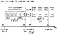
図14は、LRフレームの高信頼性配信に関する好ましい機構またはプロトコル1400を示す。プロトコル1400は、肯定応答(ACK)メッセージベースの機構を使用して、特定のLRピクチャが所期の受信側(例えば、SVCS1、SVCS2、または受信側)で受信されたことを送信側(例えば、送信側、SVCS1、またはSVCS2)に示す。図14に示される時間軸を参照すると、肯定応答が指定の時間間隔(例えば1ラウンドトリップ時間(RTT))内に受信されない場合に、送信側のタイマが、所与のLRピクチャの再送信を開始する。LRピクチャに関する通常の周期的または静的構造定義を使用することに加えて、動的構造を使用することも可能である。この場合、LRピクチャが、システム操作で動的に定義される。送信側が、送信したストリーム中の特定のフレームの受信に関する肯定応答をすべての受信側から受信した後、ビデオ通信システムは、このフレームをLRフレームと指定し、それを新しいアンカまたは同期ポイントとして使用することができる。言い換えれば、特定のピクチャを正しく受信したことをすべての受信側が確認した後に、送信側エンコーダは、特定のピクチャをLRピクチャとして使用する。送信側は、特定のLRピクチャが古くなりすぎた場合にそれを放棄し、任意の時刻により新しいピクチャを用いて新しい再同期ポイントを確立することを試みることができる。否定応答(NACK)メッセージが肯定ACKメッセージの代わりに使用される場合、プロトコル1200の動作は同様である。この場合、送信側は、NACKの受信時に直ちに所与のピクチャを再送信する。
FIG. 14 shows a preferred mechanism or
SVCSが通信システム内に存在するとき、任意選択で、SVCSは、ACKメッセージに関する集約ポイント(aggregation point)として働くことができる。そのような場合、SVCSは、すべての所期の上流の受信側がLRピクチャを受信したことを示す単一のサマリ肯定応答メッセージだけを送信側に送ることができる(「集約モード」)。この機能は、通信システムの異なる構成要素間の制御メッセージトラフィックを最小限に抑える助けになる。あるいは、SVCSは、ACKメッセージに関する終了ポイントとして働くこともできる(「ACK終了モード」)。このモードでは、SVCSは、受信したLRピクチャを直ちに確認し、それをキャッシュする。この場合、送信側は、SVCSから上流側の他の受信側からさらに肯定応答を予期しない。次いで、「終了モード」SVCSは、高信頼性配信を保証するための必要に応じて、下流側SVCSまたは受信側への再送信を実施し、すべての受信側が受信を確認した後に、そのキャッシュからLRピクチャを除去する。このモードを利用して、接続に問題のある特定の受信側/エンドポイントを分離することができ、その結果、他のエンドポイント間の通信が影響を受けない。ACK終了モードでは、送信側でピクチャをLRピクチャと動的に定義することはもはや可能ではなく、したがって、この場合は周期的または静的LR構造定義が適切となることに留意されたい。 Optionally, when SVCS is present in the communication system, SVCS can serve as an aggregation point for ACK messages. In such a case, the SVCS may send only a single summary acknowledgment message to the sender indicating that all intended upstream receivers have received the LR picture (“aggregation mode”). This feature helps to minimize control message traffic between different components of the communication system. Alternatively, the SVCS can serve as an end point for ACK messages (“ACK end mode”). In this mode, the SVCS immediately checks the received LR picture and caches it. In this case, the transmitting side does not expect further acknowledgments from other receiving sides upstream from the SVCS. The “termination mode” SVCS then performs retransmissions to the downstream SVCS or receiver as necessary to ensure reliable delivery, and after all receivers confirm receipt, from its cache Remove LR picture. This mode can be used to isolate specific receivers / endpoints that have connection problems so that communication between other endpoints is not affected. Note that in the ACK termination mode, it is no longer possible to dynamically define a picture as an LR picture at the sender side, so periodic or static LR structure definition is appropriate in this case.
図14を参照すると、例示的プロトコル1200の動作(肯定応答を伴うが、ACK集約または終了を伴わない)の詳細を理解することができる。この図は、例えば2つの別々のSVCSユニット1および2を介して通信する、送信側および受信側を示す。プロトコル1200の動作は一般に、SVCSが使用されないシステム(例えば、送信側と受信側の間に直接的接続を有するシステム)、および1つまたは複数のSVCSが使用されるシステムと同じであることを理解されよう。
Referring to FIG. 14, the details of the operation of the example protocol 1200 (with acknowledgment but not ACK aggregation or termination) can be understood. The figure shows a sender and a receiver communicating, for example, via two
図14を参照すると、送信側は、時刻 (time instant)t0でのLRステータスに関する候補であるL0フレームを送信する。フレームは、1つまたは複数のトランスポート層パケットで移送することができる。本明細書での説明の都合上、単一のパケットが使用されることを想定することがある。さらに、再送信が紛失した特定のフラグメントに影響を及ぼすことになるが、必ずしもフレーム全体には影響を及ぼさない場合にフレーム断片化が使用される場合、動作は同一である。 Referring to FIG. 14, the transmission side transmits an L0 frame that is a candidate for the LR status at time (time instant) t0. The frame can be transported in one or more transport layer packets. For the purposes of the description herein, it may be assumed that a single packet is used. In addition, the operation is the same if frame fragmentation is used when retransmissions will affect certain fragments that are lost, but not necessarily affect the entire frame.
LRフレーム(LR)を含むパケットは、所与の時刻t1〜t0内にSVCS1に到来すると予想される。その時刻に、送信側は、SVCS1がそのフレームについての肯定応答メッセージ(ACK)を生成することを予期する。そのようなACKがシステムのラウンドトリップ時間(RTT)内に受信されない場合、送信側は、パケットが紛失したと仮定し、時刻t2にLRフレームを再送信する。次にフレームがSVCS1で受信されると仮定する。フレームをSVCS2にも転送するSVCS1により、送信側に対してACKが生成される。送信側と同様に、SVCS1も、SVCS2がフレームの受信を確認するまで、そのフレームの再送信を何回か行う。図14は、SVCS1により、LRフレームがSVCS2によって時刻t6に受信されることを示す。次いで、SVCS2は、受信側からACK(例えばACK1410)を(例えば時刻t8に)受信するまで、受信側へのフレームの送信を保つ。(中継SVCSではなく)エンドユーザ受信側がLRフレームを受信したとき、エンドユーザ受信側は、将来のピクチャのコーディングのための基準ピクチャとして使用することのできる、この新しい、正しく受信されたフレームを現在有していることを元の送信側に通知する。このACK1410はSVCSを介して伝播し、送信側に(例えば時刻t10に)到達する。特定のビデオ通信セッションでのすべての受信側が新しいLRフレームの正しい受信を確認した後、送信側は、送信したフレームを基準ピクチャとして使用することができる。
A packet containing an LR frame (LR) is expected to arrive at SVCS1 within a given time t1 to t0. At that time, the sender expects SVCS1 to generate an acknowledgment message (ACK) for that frame. If no such ACK is received within the system round trip time (RTT), the sender assumes that the packet has been lost and retransmits the LR frame at time t2. Now assume that the frame is received at SVCS1. An ACK is generated to the transmission side by SVCS1 which also transfers the frame to SVCS2. Similar to the sending side, SVCS1 retransmits the frame several times until SVCS2 confirms receipt of the frame. FIG. 14 shows that the LR frame is received by SVCS2 at time t6 by SVCS1. Next, the
前述のように、H.264ビデオコーディング標準では、送信したフレームを基準ピクチャとして使用することが、候補送信済みピクチャを長期基準ピクチャとしてマークすることによって促進される。他のコーディング方式で同様のマーキング技法を使用することができる。肯定ACKがすべての受信側から収集されるまで、候補送信済みピクチャは基準ピクチャとして使用されない。LRプロトコル1400が実行中の時間全体にわたって、送信側は、符号化ビデオの送信を保つことに留意されたい。言い換えれば、プロトコルによって要求される潜在的再送信のためにこうむる追加のエンドツーエンド遅延が存在しない。LR処理機構の目的の1つは、将来のピクチャのコーディングのために信頼性の高い基準ピクチャを作成することである。実際には、LRピクチャの元の送信が破壊され、特定の受信側で適切に表示されない可能性がある。送信側(またはSVCS)は、そのピクチャが特定の受信側によって正しく受信されるまでそのピクチャの再送信を保つことになり、一方受信側は、送信側が引き続き送信する後続のビデオフレームの復号化および再生を試みることを保つことになる。
As mentioned above, the H.264 video coding standard facilitates using a transmitted frame as a reference picture by marking a candidate transmitted picture as a long-term reference picture. Similar marking techniques can be used with other coding schemes. Candidate transmitted pictures are not used as reference pictures until positive ACKs are collected from all receivers. Note that the sender keeps transmitting the encoded video for the entire time that the
図15は、否定応答(NACK)を使用するプロトコル1500の動作を示す。ACKを使用するプロトコルの動作との違いは、ここでは、LRピクチャが受信されず、紛失したときを検出する作業を受信側エンドポイントまたはSVCSが有することである。RTPおよびH.264伝送での紛失検出のための特定の技法が、本明細書の後で説明される(例えば図16〜24を参照)。こうした技法は、後続のピクチャの受信時の紛失の検出を可能にする。プロトコル1500の動作において、受信側エンドポイントまたはSVCSがLRピクチャが欠落(紛失)したことを検出したとき、受信側エンドポイントまたはSVCSは、送信側エンドポイントまたはSVCSにNACKメッセージを送信する。次いで、送信側エンドポイントまたはSVCSは、そのキャッシュから紛失ピクチャを取得し、紛失フレーム、または受信側がそのデコーダとの再同期することを可能にするより最近のLRピクチャを再送信する。
FIG. 15 shows the operation of
引き続き図15を参照して、図9のピクチャコーディング構造が使用され(4つの時間層LRおよびL0〜L2)、送信側および受信側がSVCSを介して通信すると仮定する。さらに、送信側で時刻t0に送信されるLRピクチャが紛失し、その後に続くピクチャであるL0ピクチャが首尾よくSVCSに送信されると仮定する。L0ピクチャの受信時に、SVCSは、参照されるLRピクチャが紛失したことを検出し、NACKを送信し、NACKは時刻tRで送信側で受信される。その間に、送信側も時刻t2でL1フレームを送信している。時刻tRでのNACKの受信時に、送信側は、最新のLRピクチャをSVCSに再送信する。送信側は、適切な時間間隔で元のピクチャストリームを引き続き送信し、例えば時刻t3でL2ピクチャを送信し、時刻t4でL1ピクチャを送信する。SVCSは、必要なLRピクチャが失われたかどうかにかかわらず、送信側から首尾よく受信したどんなピクチャも下流の受信側に直ちに転送することに留意されたい。受信側へのすべてのそのような伝送が成功したと仮定すると、再送信されたLRピクチャが受信側で受信されたとき、受信側は、以前の時刻t3およびt4で受信したL0およびL1ピクチャを復号化するのに必要なすべての情報を有することになる。こうしたピクチャを表示するのは遅すぎる可能性があるが、受信側(例えば、ピクチャを復号化しているがそれを表示していない「回復モード」において)は、時刻t5に到来するL2ピクチャの正しい復号化のために正しい基準ピクチャを有する目的で、こうしたピクチャを復号化することができる。受信側が十分なCPUパワーを有する場合、この復号化は、リアルタイムよりも高速に実施することができる。時刻t5で、受信側は、紛失による遅延を招くことなく、誤りのない着信ビデオ信号の通常の復号化および表示を開始することができる。代わりに、受信側がLR、L0、およびL1ピクチャをL2より前に表示することを選んだ場合、SVCSが紛失LRピクチャを回復するのにかかる時間量だけ、通信セッションの通常の(損失のない)エンドツーエンド遅延が増大することに留意されよう。この追加の遅延は、対話式通信では望ましくなく、その除去が本発明の利点の1つである。 With continued reference to FIG. 15, assume that the picture coding structure of FIG. 9 is used (four time layers LR and L0-L2) and that the sender and receiver communicate via SVCS. Further, it is assumed that the LR picture transmitted at time t0 is lost on the transmission side, and the L0 picture that is a subsequent picture is successfully transmitted to the SVCS. Upon reception of the L0 picture, the SVCS detects that the referenced LR picture is lost, transmits a NACK, and the NACK is received on the transmission side at time tR. Meanwhile, the transmitting side is also transmitting the L1 frame at time t2. When receiving a NACK at time tR, the transmitting side retransmits the latest LR picture to the SVCS. The transmission side continues to transmit the original picture stream at an appropriate time interval, for example, transmits an L2 picture at time t3, and transmits an L1 picture at time t4. Note that SVCS immediately forwards any picture successfully received from the sender to the downstream receiver, regardless of whether the required LR pictures have been lost. Assuming that all such transmissions to the receiver were successful, when the retransmitted LR picture is received at the receiver, the receiver will receive the L0 and L1 pictures received at the previous times t3 and t4. You will have all the information you need to decrypt. It may be too late to display such a picture, but the receiver (e.g. in “recovery mode” that is decoding the picture but not displaying it) is correct for the L2 picture coming at time t5. Such pictures can be decoded in order to have the correct reference picture for decoding. If the receiving side has sufficient CPU power, this decoding can be performed faster than in real time. At time t5, the receiving side can start normal decoding and display of error-free incoming video signals without incurring delays due to loss. Instead, if the receiver chooses to display the LR, L0, and L1 pictures before L2, the normal (lossless) of the communication session for the amount of time it takes for SVCS to recover the lost LR picture Note that the end-to-end delay is increased. This additional delay is undesirable in interactive communication and its removal is one of the advantages of the present invention.
RTCPまたは他のフィードバック機構を使用すると、特定の受信側がパケットの紛失を受けていることを、例えば上述の肯定応答および否定応答技法を使用して送信側に通知することができる。フィードバックは、個々のパケットについての個々のACK/NACKメッセージと同様に詳述することができる。フィードバックの使用により、エンコーダがデコーダの状態を(厳密または近似的に)計算し、それに応じて動作することが可能となる。このフィードバックは、信頼性およびランダムアクセス制御(RRC)モジュール530(図6)で生成および収集される。次いで、RRCモジュールは、適宜、イントラマクロブロックを使用し、またはエンコーダの周波数を増加させて、必要なときに同期プロセスをさらに助けるようにエンコーダに命令することができる。 Using RTCP or other feedback mechanism, a particular recipient can be notified to the sender using, for example, the acknowledgment and negative acknowledgment techniques described above. Feedback can be detailed as well as individual ACK / NACK messages for individual packets. The use of feedback enables the encoder to calculate (exactly or approximately) the state of the decoder and operate accordingly. This feedback is generated and collected in a reliability and random access control (RRC) module 530 (FIG. 6). The RRC module can then instruct the encoder to further assist the synchronization process when needed, using intra macroblocks or increasing the frequency of the encoder as appropriate.
肯定応答が使用されるとき、パケットの紛失を受けた受信側が符号化ビットストリームを再同期することを可能にするために、送信側は、最新のLRピクチャを基準ピクチャとして使用して現フレームを符号化することを選ぶことができる。このLRピクチャが確実に受信されたという肯定応答と共に、送信側は、LRピクチャを基準として使用して、現ピクチャをPピクチャとして符号化することができる。受信側が現ピクチャを正しく受信した後、そのポイント以降、受信側は、基準ピクチャバッファの内容に関してエンコーダと同期することができる。言い換えれば、デコーダに存在するどんなドリフトも解消される。 When acknowledgment is used, the sender uses the latest LR picture as the reference picture to determine the current frame in order to allow the receiver that has lost the packet to resynchronize the encoded bitstream. You can choose to encode. With an acknowledgment that this LR picture has been received reliably, the sender can encode the current picture as a P picture using the LR picture as a reference. After the receiving side has correctly received the current picture, after that point, the receiving side can synchronize with the encoder with respect to the contents of the reference picture buffer. In other words, any drift that exists in the decoder is eliminated.
同様に、否定応答が使用されるとき、デコーダは、所与のピクチャのすべての必要な基準ピクチャの到来が表示には遅すぎる場合であっても、それを復号化することによってビットストリームと再同期することができる。デコーダがリアルタイムよりも高速にピクチャを復号化することができる(言い換えれば、復号化時間がピクチャ間の時間よりも短い)場合、デコーダは最終的に、受信したビットストリームと同期することになる。同期ポイントで表示を開始することにより、デコーダは、通信セッションに更なるエンドツーエンド遅延を与えることなく、通常の復号化および表示動作を続行することができる。 Similarly, when a negative response is used, the decoder regenerates the bitstream by decoding it even if the arrival of all the required reference pictures for a given picture is too late for display. Can be synchronized. If the decoder can decode pictures faster than real time (in other words, the decoding time is shorter than the time between pictures), the decoder will eventually be synchronized with the received bitstream. By starting the display at the synchronization point, the decoder can continue normal decoding and display operations without adding additional end-to-end delay to the communication session.
受信側の再同期のためのこうした技法は、例えば5〜10人を超える参加者が関係する大きなビデオ会議に対する媒体で明らかな利点を有する。そのような会議では、パケット紛失を受けた受信側の再同期を可能にするためにIフレームを使用することは、すべての参加者に対してかなりの帯域幅の犠牲を課すことになる。実際には、最も弱いリンク上の参加者(すなわち最も誤りの多い参加者)が、最も強いリンクを有する参加者の品質を要求する。LRピクチャを使用することにより、イントラピクチャの使用が不要になる。フレーム間の時間的距離がそれほど大きくない限り、LRピクチャに基づくPピクチャも帯域幅オーバヘッドを有するが、オーバヘッドはIピクチャよりも著しく小さい。再同期のためのLRP技法は、ラウンドトリップ遅延、サーバの分散などのシステムパラメータにも適合する。システムが良好であるほど、LRピクチャが受信側で正確に受信されたものとして確立されるのが早くなり、LRベースのピクチャに関する予測が良好となり、その結果、オーバヘッドが小さくなる。 Such techniques for receiver resynchronization have obvious advantages in medium for large video conferences involving, for example, more than 5-10 participants. In such a conference, using I-frames to allow receivers that have lost packets to resynchronize imposes a significant bandwidth penalty on all participants. In practice, the participant on the weakest link (i.e. the participant with the most errors) requires the quality of the participant with the strongest link. By using the LR picture, it is not necessary to use an intra picture. Unless the temporal distance between frames is too large, P pictures based on LR pictures also have bandwidth overhead, but the overhead is significantly smaller than I pictures. The LRP technique for resynchronization also adapts to system parameters such as round trip delay, server distribution, etc. The better the system, the faster the LR picture will be established as correctly received at the receiving side, the better the prediction for LR based pictures, and the lower the overhead.
フィードバックが使用されるとき、LRフレームの構造を事前に判定する必要がないことがあることに留意されたい。実際には、すべての受信側からフィードバックを収集および照合することにより、LRフレームの構造を統計的かつ動的に確立することができる。すべての受信側で受信されたものとして確認されたフレームをLRフレームであると自動的にみなすことができる。 Note that when feedback is used, it may not be necessary to pre-determine the structure of the LR frame. In practice, the structure of the LR frame can be statistically and dynamically established by collecting and collating feedback from all receivers. A frame confirmed as having been received by all receivers can be automatically regarded as an LR frame.
LRピクチャの欠点は、ある場合に、テレビ会議への単一の不十分な接続が依然として、関係するすべての参加者についての品質が低下させることである。そのような場合、残りの参加者が影響を受けずに会議を続行すると共に、中間SVCSが、送信側プロキシの役割を果たし、必要なデータの再送信を保つことができる。例えば、転送側SVCSの隣接するSVCSまたは接続されたエンドポイントへの接続が、そのピアからの肯定応答を達成するための時間が事前構成された値よりも長いようなものである場合、そのエンドポイントが肯定応答を送り返した(適切なACKを送り返すことを含む)かのようにそのエンドポイントを扱うように転送側SVCSを構成することができる。この構成は、全システム上の問題のあるエンドポイントまたはSVCS接続の効果を限定する。それ以後、LRフレームが復号化プロセスを最終的に再同期するのに必要な最小限の情報であるので、転送側SVCSは、LRフレームのみをその問題のあるピアに送信することになる。より新しいLRフレームが送信側から転送側SVCSに到来している場合、それが、問題のあるSVCSまたはエンドポイントに引き続き再送信され、それによって、送信側ビットストリームと同期するさらなる機会が、問題のあるSVCSまたはエンドポイントに与えられる。(LR以外の)他のフレームはこのリンク上で伝送されないので、そのような再送信から追加の輻輳が生じる可能性はない。実際には、そのようなキャッシュされ、再送信されるLRフレームの数が一定の事前定義された数(例えば2〜3)を超過する場合、転送側SVCSは、特定の問題のSVCSまたはエンドポイント接続を終了することを考慮することができる。次いで、終了したSVCSまたはエンドポイントは、それにとって利用可能な任意の適切なランダムエントリ機構を使用して、ビデオ会議セッションに再加入しなければならなくなる。 The disadvantage of LR pictures is that in some cases a single poor connection to a video conference will still degrade the quality for all participants involved. In such a case, the remaining participants continue the conference unaffected and the intermediate SVCS can act as a sender proxy and keep the necessary data retransmissions. For example, if the forwarding SVCS's connection to an adjacent SVCS or connected endpoint is such that the time to achieve an acknowledgment from that peer is longer than a preconfigured value, the end The forwarding SVCS can be configured to treat that endpoint as if the point sent back an acknowledgment (including sending back an appropriate ACK). This configuration limits the effectiveness of problematic endpoints or SVCS connections on the entire system. From then on, since the LR frame is the minimum information necessary to finally resynchronize the decoding process, the forwarding SVCS will only send the LR frame to the problematic peer. If a newer LR frame is arriving from the sender to the forwarding SVCS, it will continue to be retransmitted to the problematic SVCS or endpoint, thereby providing further opportunities to synchronize with the sender bitstream. Given to some SVCS or endpoint. Since no other frames (other than LR) are transmitted on this link, no additional congestion can result from such retransmissions. In practice, if the number of such cached and retransmitted LR frames exceeds a certain predefined number (e.g. 2 to 3), then the forwarding SVCS will determine the particular problem SVCS or endpoint It can be considered to terminate the connection. The terminated SVCS or endpoint will then have to re-join the video conference session using any suitable random entry mechanism available to it.
接続またはリンク中断が一時的である場合、受信側エンドポイントは、再送信されたLRフレームをその正しい順序で復号化し、セッションに再加入することができる。LRフレーム数は、合計フレーム数よりもずっと少ないと予想されるので、CPU負荷は問題とはならず、受信側エンドポイントは、復号化プロセスについて行くことができる。 If the connection or link break is temporary, the receiving endpoint can decode the retransmitted LR frames in their correct order and rejoin the session. Since the number of LR frames is expected to be much less than the total number of frames, the CPU load is not an issue and the receiving endpoint can follow the decoding process.
図14に示されるプロトコル1400は例示的なものであり、別のシステム性能改善のために容易に修正できることを理解されよう。例えば、修正後プロトコル1400では、はるばる送信側まで戻る肯定応答(例えば図14に示されるACK[RCVR]メッセージ)は、受信側エンドポイントで発信される必要はなく、連鎖中のエンドポイントに最も近い最後のSVCSから発信されるだけでよい。エンドポイントに接続される最後のSVCSは、まずACK[RCVR]を送り戻し、次いで上述のようにエンドポイントにLRフレームを確実に送信または再送信することに進むことができる。このプロトコル1400の修正は、ACK[RCVR]に送り戻す前に、事前構成された時間待機する必要を回避する。
It will be appreciated that the
当業者には明らかであろうが、本発明の原理に従って、LRフレームの高信頼性伝送を実装するのに使用されるARQプロトコル(例えばプロトコル1400)を他の適切なトランスポート層機構で置き換えることができる。高信頼性伝送に適したトランスポート層機構は、プロアクティブ再送信(proactive retransmission)などの機構と、インターリービングを伴うリードソロモンコード(Reed-Solomon codes with interleaving)、ハイブリッドFEC-ARQ技法(例えばRubenstein等、Computer Comm.Journal、2001年3月を参照)などのより洗練されたFEC(前方誤り訂正)技法とを含む。 As will be apparent to those skilled in the art, in accordance with the principles of the present invention, the ARQ protocol (eg, protocol 1400) used to implement reliable transmission of LR frames is replaced with other suitable transport layer mechanisms. Can do. Transport layer mechanisms suitable for reliable transmission include mechanisms such as proactive retransmission, Reed-Solomon codes with interleaving, and hybrid FEC-ARQ techniques (e.g. Rubenstein). And more sophisticated FEC (forward error correction) techniques such as Computer Comm. Journal, March 2001).
本発明の実装での重要な考慮すべき点は、受信側(例えば受信側エンドポイントまたはSVCS)がLRピクチャが紛失したことをどのように最小の遅延で検出するかということである。本発明は、ピクチャ番号およびピクチャ番号基準に基づく技法を含む。この技法は、LRピクチャパケットと共に搬送されるLRピクチャに順次的番号を割り振ることによって動作する。受信側は、受信したLRピクチャの番号のリストを維持する。一方、非LRピクチャは、復号化順序での最新のLRピクチャのシーケンス番号を含む。このシーケンス番号基準は、受信側が紛失LRピクチャを、その後に続くLRピクチャの受信前であっても検出することを可能にする。受信側がLRピクチャを受信したとき、そのピクチャ番号を、受信側が維持するピクチャのリストと比較することにより、前のLRピクチャのうちの1つまたは複数を紛失したかどうかを検出することができる(受信したピクチャ数は前のピクチャより1つ大きいはずであり、カウントが再スタートした場合、0であるはずである)。受信側が非LRピクチャを受信したとき、受信側は、参照されるLRピクチャがその番号リスト内に存在するかどうかを確認するためにテストする。参照されるLRピクチャが番号リスト内に存在しない場合、それは紛失したと想定され、訂正処置を開始することができる(例えば、NACKメッセージが送信側に送り戻される)。 An important consideration in the implementation of the present invention is how the receiver (eg, receiver endpoint or SVCS) detects the loss of the LR picture with minimal delay. The present invention includes techniques based on picture numbers and picture number criteria. This technique works by assigning sequential numbers to LR pictures carried with LR picture packets. The receiving side maintains a list of received LR picture numbers. On the other hand, the non-LR picture includes the sequence number of the latest LR picture in decoding order. This sequence number criterion allows the receiver to detect a missing LR picture even before receiving a subsequent LR picture. When the receiver receives an LR picture, it can detect whether one or more of the previous LR pictures have been lost by comparing the picture number with the list of pictures maintained by the receiver ( The number of pictures received should be one greater than the previous picture, and should be 0 when the count is restarted). When the receiving side receives a non-LR picture, the receiving side tests to see if the referenced LR picture exists in its number list. If the referenced LR picture is not in the number list, it is assumed to be lost and corrective action can be initiated (eg, a NACK message is sent back to the sender).
フラグまたは他のシングナリング手段(例えば、他のパケットヘッダまたはパケットペイロードパラメータによって導出される)を使用してLRピクチャをLRピクチャであると識別することができ、またはその存在を示唆することができる(例えば、符号化ビデオシーケンス中のその順序によって)。LRピクチャ番号の使用の例示として、LR、L0の順序で送信される2つのピクチャLRおよびL0のシーケンスを仮定する。受信側の番号リストは当初は空である。さらに、LRピクチャにシーケンス番号0が割り当てられると仮定する。LRピクチャは、そのパケット内に示される番号0と共に送信される。L0ピクチャはまた、最新のLRピクチャである、それが依存するLRピクチャに対する参照として、同一の番号0と共に送信される。LRピクチャが紛失した場合、受信側は、番号0を有するLRピクチャに対する参照を含むフレームL0を受信する。この番号はリスト内にない(リストはまだ空である)ので、受信側は、番号0を有するLRピクチャが紛失したことを検出する。次いで、受信側は、紛失LRピクチャの再送信を要求することができる。
A flag or other signaling means (e.g., derived by other packet header or packet payload parameters) can be used to identify the LR picture as an LR picture, or to indicate its presence (Eg, by its order in the encoded video sequence). As an illustration of the use of LR picture numbers, assume a sequence of two pictures LR and L0 transmitted in the order LR, L0. The receiver's number list is initially empty. Further assume that
LRピクチャ番号技法を使用する紛失LRピクチャの検出は、受信側エンドポイントと中間SVCSの両方で実施できることに留意されたい。例えば、LRP(Rcv)モジュール270B(図2および3)、またはモジュール470B(図4)で操作が実施される。
Note that detection of lost LR pictures using the LR picture number technique can be performed at both the receiving endpoint and the intermediate SVCS. For example, the operation is performed in the LRP (Rcv)
LRピクチャ番号付け技法について2つの異なる実施形態が本明細書では開示されている。一実施形態(以後「Rパケット」技法と呼ぶ)は、伝送のためにRTPプロトコルがシステムで使用されるときに適切である。他の実施形態は、システムに対してH.264 Annex G(SVC)ドラフト標準が使用されるときに適用可能である。 Two different embodiments for LR picture numbering techniques are disclosed herein. One embodiment (hereinafter referred to as the “R packet” technique) is appropriate when the RTP protocol is used in the system for transmission. Other embodiments are applicable when the H.264 Annex G (SVC) draft standard is used for the system.
Rパケット技法では、恐らくは1つまたは複数の中間サーバを介する、2つの端末間の通信のために、(UDPおよびIPを介する)RTPプロトコルが使用される。メディア送信端末は、リアルタイム符号化を実施することができ、またはローカルストレージまたは他のストレージ(RAM、ハードディスク、記憶域ネットワーク、ファイルサーバなど)からのメディアデータにアクセスすることができる。同様に、受信側端末はリアルタイム復号化を実施することができ、受信データを将来の再生のためにローカルストレージまたは他のストレージに格納していることができ、あるいはその両方である。本明細書の説明では、限定はしないが、リアルタイム符号化および復号化が行われていると仮定する。 In the R packet technique, the RTP protocol (over UDP and IP) is used for communication between two terminals, possibly via one or more intermediate servers. The media sending terminal can perform real-time encoding or can access media data from local storage or other storage (RAM, hard disk, storage network, file server, etc.). Similarly, the receiving terminal can perform real-time decoding and can store the received data in local storage or other storage for future playback, or both. The description herein assumes, without limitation, real-time encoding and decoding.
図16は、送信側端末のLRP Sndモジュール(例えば図2のモジュール270A)のアーキテクチャを示す。LRP Sndモジュールは、再送信を必要とする可能性のあるパケットのためにローカルストレージ(例えばバッファ1605)を有するパケットプロセッサ(R-Packetコントローラ1610)を含む。R-Packetコントローラ1610はRパケットをマークし、さらにはRNACKに応答する。Rパケットコントローラは、RTP/UDP/IPプロトコルスタックを実装するマルチプレクサMUX1620およびデマルチプレクサDMUX1630に接続される。図16ではMUX1620およびDMUX1630が別々の実体として示されているが、これらを同一のユニットとして組み合わせることができる。MUX1620およびDMUX1630は、物理層インターフェースを提供する1つまたは複数のネットワークインターフェースコントローラ(NIC)に接続される。好ましい実施形態では、NICはイーサネット(登録商標)アダプタであるが、当業者には明らかであろうが、他のどんなNICも使用することができる。
FIG. 16 shows the architecture of the LRP Snd module (eg,
同様に、図17は、受信側端末のLRP Rcvモジュール(例えば図2のモジュール270B)の例示的アーキテクチャを示す。ここでは、R-Packetコントローラ(例えばコントローラ1610')は、Rパケット紛失検出と、適切なNACKメッセージの生成の任を担う。さらに、図18は、サーバのLRP SndおよびRcvモジュール(例えば図4のモジュール420Aおよび420B)の構造を示し、サーバのLRP SndおよびRcvモジュールは、バックツーバックに接続された受信側端末の構成要素および送信側端末の構成要素と同じでよい。
Similarly, FIG. 17 shows an exemplary architecture of the receiving terminal's LRP Rcv module (eg,
好ましい実施形態では、送信側端末は、RTP仕様に従ってメディアデータをパケット化する。RTPに対して様々なパケット化(「ペイロード」と呼ばれる)フォーマットが定義されるが、それらは同一の共通ヘッダを共有することに留意されたい。本発明は、Rパケットを適切に処理することができるように、RTPパケットに対して名前付きヘッダ拡張機構(Singer,D.、「A general mechanism for RTP Header Extensions」、draft-ietf-avt-rtp-hdrext-01(進行中の研究)、2006年2月を参照)を導入する。 In a preferred embodiment, the sending terminal packetizes media data according to the RTP specification. Note that although various packetization (called “payload”) formats are defined for RTP, they share the same common header. In the present invention, named header extension mechanisms (Singer, D., “A general mechanism for RTP Header Extensions”, draft-ietf-avt-rtp) are applied to RTP packets so that R packets can be processed appropriately. -hdrext-01 (ongoing research), see February 2006).
本発明によれば、Rパケットを含むRTPセッションでは、個々のRパケットが、名前付きヘッダ拡張機構でマークされる。Rパケットヘッダ拡張要素は、Rパケット自体と、以前に送られたRパケットの両方を識別する。このヘッダ拡張要素は、例えば「com.layeredmedia.avt.r-packet/200606」という名前を有する。あらゆるRパケットは、この形態のヘッダ拡張要素を含み、あらゆる非Rパケットはこの形態のヘッダ拡張要素を含むべきである。 According to the present invention, in an RTP session that includes R packets, each R packet is marked with a named header extension mechanism. The R packet header extension element identifies both the R packet itself and the previously sent R packet. The header extension element has a name “com.layeredmedia.avt.r-packet / 200606”, for example. Every R packet should contain this form of header extension element, and every non-R packet should contain this form of header extension element.
図19は、本発明の名前付きヘッダ拡張の例示的データフィールドフォーマットを示し、その中ではフィールドが以下のように定義される。 FIG. 19 shows an exemplary data field format of the named header extension of the present invention, in which the fields are defined as follows:
ID:4ビット
例えばSinger,D.、「A general mechanism for RTP Header Extensions」、draft-ietf-avt-rtp-hdrext-01(進行中の研究)、2006年2月で定義された、このヘッダ拡張要素について取り決められたローカル識別子。
ID: 4 bits This header extension as defined in Singer, D., `` A general mechanism for RTP Header Extensions '', draft-ietf-avt-rtp-hdrext-01 (ongoing research), February 2006 Local identifier negotiated for the element.
長さ(len):4ビット
ヘッダバイト(IDおよびlen)をカウントしない、このヘッダ拡張要素のデータバイトの長さから1を引いたもの。これは、第2ワード(置換される範囲)が存在する場合に値6を有し、第2ワードが存在しない場合に2を有する。したがって、この値は2または6でなければならない。
Length (len): 4 bits The length of the data byte of this header extension element minus 1 which does not count header bytes (ID and len). This has a value of 6 if the second word (range to be replaced) is present and 2 if no second word is present. Therefore, this value must be 2 or 6.
R:1ビット
このヘッダ拡張要素を含むパケットがRシーケンス番号RSEQを有する系列SER中のRパケットであることを示すビット。このビットがセットされていない場合、その代わりに、ヘッダ拡張要素が、メディアストリームの系列SER中の最新のRパケットがRシーケンス番号RSEQを有していたことを示す。このビットがセットされていない場合、置換される範囲が存在すべきではなく(すなわち、lenフィールドは2であるべきである)、存在する場合、無視されなければならない。
R: 1 bit A bit indicating that the packet including this header extension element is an R packet in the sequence SER having the R sequence number RSEQ. If this bit is not set, the header extension element instead indicates that the most recent R packet in the media stream sequence SER had an R sequence number RSEQ. If this bit is not set, the range to be replaced should not exist (ie, the len field should be 2) and if present, it must be ignored.
予約済み、0でなければならない(MBZ):3ビット
予約済みビット。これは送信時に0にセットされなければならず、受信時には無視される。
Reserved, must be 0 (MBZ): 3 bits Reserved bit. This must be set to 0 on transmission and ignored on reception.
系列ID(SER):4ビット
このヘッダ拡張要素で記述されているRパケットの系列の識別子。メディアエンコーダが単一の系列のRパケットを記述している場合、これは値0を有するべきである。例えば、図13に示されるスケーラブルビデオピクチャコーディング構造を使用して、Lパケット(ベース空間拡張層、全スレッド)は、例えば0にセットされたSERを有することになり、Sパケット(空間拡張層、全スレッド)は、1にセットされたSERを有することになる。
Sequence ID (SER): 4 bits The identifier of the R packet sequence described in this header extension element. If the media encoder describes a single sequence of R packets, this should have the
Rパケットシーケンス番号(RSEQ):16ビット
系列SER内のこのRパケットの番号を示す符号なしシーケンス番号。この値は、所与の系列で送られるRパケットごとに1だけ増分される(modulo 2^16)。別々のシーケンスについてのRSEQ値は独立である。
R packet sequence number (RSEQ): 16 bits An unsigned sequence number indicating the number of this R packet in the sequence SER. This value is incremented by 1 for every R packet sent in a given sequence (modulo 2 ^ 16). RSEQ values for separate sequences are independent.
置換される範囲の開始(SUPERSEDE_START):16ビット
modulo 2^16で計算される、このRパケットによって置換される、包含的な、最初のRパケットのRシーケンス番号(この値は剰余演算を使用するので、置換される範囲の終わりより前のすべてのRパケットが置換されていることを示すために、SUPERSEDE_STARTについて値RSEQ+1を使用することができる)。このフィールドは任意選択であり、len=6であるときにのみ存在する。
Start of range to be replaced (SUPERSEDE_START): 16 bits
R sequence number of the first inclusive R packet to be replaced by this R packet, calculated by modulo 2 ^ 16 (this value uses a remainder operation, so everything before the end of the range to be replaced The value RSEQ + 1 can be used for SUPERSEDE_START to indicate that the R packet has been replaced). This field is optional and is only present when len = 6.
置換される範囲の終わり(SUPERSEDE_END):16ビット
modulo 2^16で計算される、このRパケットによって置換される、包含的な、最後のRパケットのRシーケンス番号。この値は、閉じた範囲[SUPERSEDE_START..RSEQ]modulo 2^16内になければならない。このフィールドは任意選択であり、len=6であるときにのみ存在する。
End of range to be replaced (SUPERSEDE_END): 16 bits
R sequence number of the last inclusive R packet replaced by this R packet, calculated in
RTPパケットは、複数のRパケットマーク要素のそれぞれがSERについて異なる値を有する限り、こうした要素を含むことができる。しかし、RTPパケットは、Rビットがセットされたこうしたヘッダ拡張要素のうちの複数を含むことはできず、すなわちRパケットは、複数の系列に属することはできない。 An RTP packet can include such elements as long as each of the multiple R packet mark elements has a different value for the SER. However, an RTP packet cannot contain more than one of these header extension elements with the R bit set, i.e. an R packet cannot belong to more than one sequence.
Rパケットを使用するメディアストリーム中のすべてのRTPパケットは、すべてのアクティブな系列についてマーク要素を含むべきである。 All RTP packets in media streams that use R packets should include a mark element for all active sequences.
このヘッダ拡張要素の第2ワードが存在するとき、このRパケットがいくつかの以前に受信されたRパケットを置換することを示し、こうしたパケットはストリーム状態を再構築するのにもはや必要ではないことを意味する。この第2ワードは、そのビットがセットされたヘッダ拡張要素内のみに現れなければならない。 Indicates that when the second word of this header extension element is present, this R packet replaces some previously received R packets, and such packets are no longer needed to reconstruct the stream state Means. This second word must appear only in the header extension element with that bit set.
Rパケットは、要素SERフィールドで識別される系列中のRパケットを置換することができるだけである。Rパケットは、他の系列中のパケットを置換することができない。 The R packet can only replace the R packet in the sequence identified in the element SER field. R packets cannot replace packets in other sequences.
置換された要素がSUPERSEDE_END=RSEQを有することは有効である。このことは、Rパケットがそれ自体を置換すること、すなわち、このRパケットがストリーム状態と直ちに無関係となることを示す。実際には、これを行う最も一般的な理由は、系列を終了させることであり、このことは、置換された範囲(SUPERSEDE_START,SUPERSEDE_END)=(RSEQ+1,RSEQ)を有する空パケットを送ることによって行うことができ(例えばRTP No-opパケット。Andreasen,F.、「A No-Op Payload Format for RTP」、draft-ietf-avt-rtp-no-op-00(進行中の研究)2005年5月を参照)、その結果、その系列は、置換されていないパケットをもはや含まない。 It is valid for the replaced element to have SUPERSEDE_END = RSEQ. This indicates that the R packet replaces itself, that is, this R packet is immediately independent of the stream state. In practice, the most common reason for doing this is to end the sequence, which sends an empty packet with the replaced range (SUPERSEDE_START, SUPERSEDE_END) = (RSEQ + 1, RSEQ) (E.g. RTP No-op packet. Andreasen, F., "A No-Op Payload Format for RTP", draft-ietf-avt-rtp-no-op-00 (work in progress) 2005 As a result, the sequence no longer contains unreplaced packets.
系列中で送られる第1Rパケットは、他のRパケットが範囲内に存在しないことを明らかにするために、置換された範囲(SUPERSEDE_START,SUPERSEDE_END)=(RSEQ+1,RSEQ-1)で送られるべきである。 The first R packet sent in the sequence is sent in the replaced range (SUPERSEDE_START, SUPERSEDE_END) = (RSEQ + 1, RSEQ-1) to reveal that no other R packet exists in the range Should.
Rパケットは、置換されるべきパケットの範囲内に、既に置換されたパケットを冗長的に含むことができる。 The R packet can redundantly include already replaced packets within the range of the packet to be replaced.
Rパケットの紛失が受信側で検出され、それが、受信側によってRTCPフィードバックメッセージを使用して送信側に示される。Rパケット否定応答(RNACK)メッセージは、例えばPT=RTPFBおよびFMT=4で識別されるRTCPフィードバックメッセージである(例えばOtt,J.等、「Extended RTP Profile for RTCP-based Feedback(RTP/AVPF)」、RFC 4585、2006年7月を参照)。本発明に従って他の値を選ぶこともできる。FCIフィールドは、少なくとも1つのRNACK含まなければならず、複数のRNACKを含むことができる。 The loss of the R packet is detected at the receiver, which is indicated by the receiver to the sender using the RTCP feedback message. The R packet negative acknowledgment (RNACK) message is, for example, an RTCP feedback message identified by PT = RTPFB and FMT = 4 (for example, Ott, J. et al., `` Extended RTP Profile for RTCP-based Feedback (RTP / AVPF) ''). , RFC 4585, see July 2006). Other values may be chosen according to the present invention. The FCI field must contain at least one RNACK and can contain multiple RNACKs.
RNACKパケットは、1つまたは複数のRパケットの紛失を示すのに使用される。紛失パケットは、パケットシーケンス番号、系列識別子、およびビットマスクによって識別される。 RNACK packets are used to indicate the loss of one or more R packets. A lost packet is identified by a packet sequence number, a sequence identifier, and a bit mask.
RNACKメッセージの構造およびセマンティクスは、AVPF Generic NACKメッセージのものと同様である。 The structure and semantics of the RNACK message are similar to those of the AVPF Generic NACK message.
図20は、RNACKフィードバック制御情報(FCI)フィールドの例示的構文(シンタックス)を示し、個々のフィールドは以下のように定義される。 FIG. 20 shows an exemplary syntax (syntax) of the RNACK feedback control information (FCI) field, and the individual fields are defined as follows.
Rパケットシーケンス番号(RSEQ):16ビット
RSEQフィールドは受信側が受信していないRSEQ値を示す。
R packet sequence number (RSEQ): 16 bits
The RSEQ field indicates an RSEQ value that has not been received by the receiver.
系列ID(SER):4ビット
このヘッダ拡張要素によってRパケットのどのシーケンスが紛失していると記述されているかの識別子。
Sequence ID (SER): 4 bits An identifier of which sequence of R packets is described as being lost by this header extension element.
後に続く紛失Rパケットのビットマスク(BLR):12ビット
BLRは、RSEQによって示されるRTPパケットの直後の12個のRパケットのいずれかの紛失を報告することを可能にする。BLPの最下位ビットをビット1と表し、BLPの最上位ビットをビット12と表すと、受信側が系列SER(modulo 2^16)中のRパケット番号(RSEQ+i)を受信していない場合にビットマスクのビットiが1にセットされ、このパケットが紛失していることを示す。そうでない場合、ビットiは0にセットされる。Rパケットのビットマスクが0にセットされていたからといって、送信側は、受信側がRパケットを受信したことを仮定してはならないことに留意されたい。例えば、RSEQに対応するパケットと、シーケンス中の後に続くRパケットとが紛失した場合、BLRの最下位ビットが1にセットされる。しかし、送信側は、BLRのビット2から15が0であるというだけでの理由でパケットRSEQ+2からRSEQ+16が受信されたことを推測することはできず、すべての送信側が認識することは、受信側がこの時に紛失したと送信側に報告していないことである。
Bit mask (BLR) of subsequent lost R packet: 12 bits
The BLR makes it possible to report the loss of any of the 12 R packets immediately following the RTP packet indicated by RSEQ. If the least significant bit of BLP is represented as
置換されていないRパケットを受信していないことを受信側が検出したとき、受信側は、RTCPの規則(例えばOtt,J.およびS.Wenger、「Extended RTP Profile for RTCP-based Feedback(RTP/AVPF)」、draft-ietf-avt-rtcp-feedback-11(進行中の研究)、2004年8月を参照)に支配されて、可能な限り早くRNACKメッセージを送信する。マルチポイントシナリオでは、これは、他の受信側からRNACKパケットを聴取し、既に報告されている紛失Rパケットに関するRNACKを送信しないことを含む。 When the receiver detects that it has not received an R packet that has not been replaced, the receiver uses RTCP rules (e.g., Ott, J. and S. Wenger, `` Extended RTP Profile for RTCP-based Feedback (RTP / AVPF ) ", Draft-ietf-avt-rtcp-feedback-11 (ongoing research), see August 2004), sending RNACK messages as soon as possible. In a multipoint scenario, this includes listening for RNACK packets from other receivers and not sending RNACK for previously reported lost R packets.
送信側がRNACKパケットを受信したとき、送信側は、パケットが置換されたかどうかをチェックする。パケットが置換されていない場合、送信側は、RNACKがそれに関して送信されたパケットを再送信する(例えば、RTP再送信ペイロードを使用して。Rey,J.等、「RTP Retransmission Payload Format」、RFC 4588、2006年7月を参照)。パケットが置換された場合、送信側は、そのRパケット要素が要求されたパケットを含む置換されたパケット範囲を示す最新のパケットを再送信する。 When the sender receives an RNACK packet, the sender checks whether the packet has been replaced. If the packet has not been replaced, the sender retransmits the packet that RNACK has transmitted about it (eg, using the RTP retransmission payload. Rey, J. et al., “RTP Retransmission Payload Format”, RFC 4588, see July 2006). If a packet is replaced, the sender resends the latest packet indicating the replaced packet range whose R packet element contains the requested packet.
送信側は、以前に送信されたパケットを再送信するのではなく、RNACKで要求されたものを置換する新しいRパケットを生成および送信することを選ぶことができる。 The sender can choose to generate and send a new R packet that replaces the one requested in the RNACK rather than retransmitting the previously sent packet.
ある期間の後、RNACKがそれに関して送信されたRパケットの再送信、またはそのパケットを置換するRパケットを受信側が受信しなかった場合、受信側はRNACKメッセージを再送信すべきである。受信側は、AVPFで許可されるよりも頻繁にRNACKメッセージを送信してはならない。可能なら、受信側は、送信側へのラウンドトリップ時間の推定を実施すべきであり、ラウンドトリップ時間当たり1度よりも頻繁にRNACKメッセージを送信すべきではない(受信側がRTP送信側としても働いており、かつ送信側が受信側のストリームに関するRTCP受信レポートを送信している場合、ラウンドトリップ時間を送信側レポートのLSRおよびDLSRフィールドから推論することができる)。ラウンドトリップ時間が利用可能ではない場合、受信側は、セットされた時間枠よりも頻繁にRNACKメッセージを送信すべきではない。潜在的値は100ミリ秒であるが、当業者には明らかなように、応用例の環境に応じて他の値が適していることもある。 After a period of time, if the receiver does not receive an R packet retransmitted by RNACK, or an R packet that replaces the packet, the receiver should retransmit the RNACK message. The receiver must not send RNACK messages more frequently than allowed by AVPF. If possible, the receiver should perform round trip time estimation to the sender and should not send RNACK messages more often than once per round trip time (the receiver should also act as the RTP sender). The round trip time can be inferred from the LSR and DLSR fields of the sender report). If the round trip time is not available, the receiver should not send RNACK messages more frequently than the set time frame. The potential value is 100 milliseconds, but other values may be suitable depending on the environment of the application, as will be apparent to those skilled in the art.
上述のRNACK機構を肯定応答「RACK」メッセージとして適用することもできる。この場合、受信側は、どのパケットが正しく受信されたかを送信側に示す。本発明の原理に従って、パケットヘッダのセマンティクスを適切に変更して、RNACKメッセージと同一の設計をこうした「RACK」に関して使用することができる。RACKメッセージは、ペイロード特有の中断を有することがあり、例えば、スライスまたは全フレームに対応する可能性がある。そのような場合、RACKメッセージは、関連するスライスまたはフレームと関係するすべての個々のパケットを確認しなければならない。 The RNACK mechanism described above can also be applied as an acknowledgment “RACK” message. In this case, the receiving side indicates to the transmitting side which packet has been correctly received. In accordance with the principles of the present invention, the same design as the RNACK message can be used for such “RACKs” with appropriate changes in packet header semantics. A RACK message may have a payload specific interruption, for example, it may correspond to a slice or an entire frame. In such a case, the RACK message must acknowledge all individual packets associated with the associated slice or frame.
RACKおよびRNACKメッセージの使用を同一のシステムで組み合わせることも可能である。 It is also possible to combine the use of RACK and RNACK messages in the same system.
R-Packet技法はいくつかの利点を有する。まず、R-Packet技法は、送信側が、生成されたRTPストリーム中のパケットのサブセットを高優先順位(R)パケットであると指示することを可能にする。 The R-Packet technique has several advantages. First, the R-Packet technique allows the sender to indicate that a subset of the packets in the generated RTP stream are high priority (R) packets.
R-Packet技法はさらに、受信側が、ストリームの何らかのパケットが受信されたときはいつでも、かつ符号化ストリームの依存関係構造の如何にかかわらず、いつRパケットを紛失したかを判定することを可能にする。 The R-Packet technique also allows the receiver to determine when an R packet is lost whenever any packet of the stream is received and regardless of the dependency structure of the encoded stream. To do.
R-Packet技法はまた、受信側が、いつRパケットを紛失したかを送信側に示すことを可能にする。このことは、紛失と識別される任意のパケットを否定応答することによって実施される。任意選択で、受信されるRパケットを受信側で肯定応答することができる。 The R-Packet technique also allows the receiver to indicate to the sender when the R packet has been lost. This is done by negatively acknowledging any packet identified as lost. Optionally, the received R packet can be acknowledged at the receiver.
さらに、R-Packet技法は、受信側が、他の非Rパケットがいくつ紛失したかにかかわらず、受信された最新のパケットの時点出どんなRパケットも紛失していないと判定することを可能にする。 In addition, the R-Packet technique allows the receiver to determine that no R packets have been lost since the last packet received, regardless of how many other non-R packets have been lost. .
さらに別の利点は、送信側が、コーデックを意識した方式(例えばH.264スライス)、またはコーデックを意識しない方式(例えばRFC3984断片化ユニット)で、フレームを任意の数のRパケットに分割することが可能となることである。 Yet another advantage is that the sender can divide the frame into any number of R packets in a codec-aware (e.g. H.264 slice) or codec-aware (e.g. RFC3984 fragmentation unit). It will be possible.
別の利点は、送信側が、Rパケットが以前のRパケットを置換したこと、すなわち、ある以前のRパケットがストリーム状態を確立するためにはもはや不要であることを示すことが可能となることである。このことは、所与のパケットの前のすべてのRパケットが置換されたこと、およびRパケットの範囲が置換されたことを示すことが共に可能であることを含む。 Another advantage is that it allows the sender to indicate that an R packet has replaced a previous R packet, i.e. that a previous R packet is no longer needed to establish a stream state. is there. This includes both being able to indicate that all R packets before a given packet have been replaced and that the range of R packets has been replaced.
最後に、別の利点は、エンコーダが、そのメディアストリームに対して、Rパケット状態を前方誤り訂正(FEC)(例えばLi,A.、「RTP Payload Format for Generic Forward Error Correction」、draft-ietf-avt-ulp-17(進行中の研究)、2006年3月を参照)ストリームから回復することを可能にする方式で、すべてのパケットまたは選択的にRパケットのみにFECを適用することが可能となることである。 Finally, another advantage is that the encoder can convert the R packet state for that media stream to forward error correction (FEC) (e.g., Li, A., `` RTP Payload Format for Generic Forward Error Correction '', draft-ietf- avt-ulp-17 (ongoing research), see March 2006) A method that allows recovery from a stream, and that FEC can be applied to all packets or selectively only R packets It is to become.
受信側がLRピクチャ(SRピクチャを含む)が最小の遅延で紛失したことを検出することを可能にする第2の例示的検出技法が、H.264 Annex G(SVC)ドラフト標準に基づくシステムに適用可能である。そのような場合、H.264 Annex G(SVC)NALユニットが、伝送のための基礎として使用される。H.264 SVCの現在の設計は、ストリームの最低の時間層(R)、またはH.264 SVCの用語における「キーピクチャ」のすべてが受信されたか否かを受信側が判定することが可能となるのに十分な情報を搬送しない。例えば、図21を参照すると、フレーム0およびフレーム3は共に、長期基準バッファ内の位置0にそれ自体を格納するキーピクチャである。フレーム4は、長期基準バッファ内の位置0を参照する。フレーム3が完全に紛失した場合、フレーム4は正しく復号化できない。しかし、H.264 Annex G(SVC)ドラフト標準の下の受信側がこのことを認識する方法がない場合、受信側は、あたかもフレーム0をフレーム4に対する基準ピクチャとして使用することができるかのように動作し、したがって不正確なイメージを表示する。
A second exemplary detection technique that allows the receiver to detect that LR pictures (including SR pictures) are lost with minimal delay applies to systems based on the H.264 Annex G (SVC) draft standard Is possible. In such cases, H.264 Annex G (SVC) NAL units are used as the basis for transmission. The current design of H.264 SVC allows the receiver to determine if all of the stream's lowest time layer (R), or “key picture” in H.264 SVC terminology, has been received. Does not carry enough information. For example, referring to FIG. 21, both
デコーダがフレーム紛失を検出することを可能にする機構は、連続するフレーム番号またはフレーム索引をキーピクチャに割り当て、非キーピクチャに、そのフレーム索引を参照することによって最新のキーピクチャを示させる。キーピクチャ索引を検討することにより、ストリーム受信側は、ストリームのキーピクチャのすべてを現フレームまで実際に受信したかどうかを判定することができる。H.264 SVC構文では、フレーム索引情報を提供することについていくつかの可能性が存在する。以下では、図23および24を参照しながら2つの代替実施形態が説明される。 A mechanism that allows the decoder to detect frame loss assigns consecutive frame numbers or frame indexes to key pictures and causes non-key pictures to point to the latest key picture by referencing that frame index. By examining the key picture index, the stream receiver can determine whether all of the key pictures in the stream have actually been received up to the current frame. In the H.264 SVC syntax, there are several possibilities for providing frame index information. In the following, two alternative embodiments will be described with reference to FIGS. 23 and 24.
図22は、現H.264 Annexドラフトで定義されるSVC NALヘッダ拡張の構造を示す(例えば、T.Wiegand、G.Sullivan、J.Reichel、H.Schwarz、M.Wien編、「Joint Draft 7,Rev.2:Scalable Video Coding」、Joint Video Team、Doc.JVT-T201、Klagenfurt、2006年7月と、J.Reichel、D.Santa Cruz、およびF.Ziliani、「On High Level Syntax」、Joint Video Team、Doc.JVT-T083(補正)、Klagenfurt、2006年7月による補正を参照。これらの文書はどちらも、その全体が参照により本明細書に組み込まれる)。図22は、3バイトヘッダの構造、ならびに個々のフィールドの名前およびそのビット長を示す。dependency_id(D)、temporal_level(T)、およびquality_level(Q)フィールドは、それぞれ空間/粗粒度品質(spatial/coarse grain quality)次元、時間次元、および細粒度品質(fine-grain quality)次元を示す。言い換えれば、これらは、スケーラブルエンコーダによって与えられる解像度の組の中のNALのペイロードの位置を示す。この方式でのベース層はD=Q=T=0で識別されることに留意されたい。
Figure 22 shows the structure of the SVC NAL header extension defined in the current H.264 Annex draft (e.g., T. Wiegand, G. Sullivan, J. Reichel, H. Schwarz, M. Wien, ``
さらに、T=Q=0であるとき、fragmented_flagフィールド、last_fragment_flagフィールド、およびfragment_orderフィールドはFGS符号化データ(Q>0)にだけ関係するので、それらは役に立たないことに留意されたい。フィールドは合計4ビットを提供する。トレイリングreserved_zero_two_bitsが含まれる場合、合計は6ビットである。同様に、T>0であるがQ=0であるとき、フィールドfragmented flag、last_fragment_flag、およびfragment_orderの合計4ビットは使用されない。トレイリング予約済みビットを追加した場合、合計は6ビットである。条件T=Q=0がキーピクチャに対応し、T>0であるがQ=0であることが非キーピクチャに対応することに留意することにより、フレーム番号付けを導入するのに使用することのできるいくつかのビットが存在することがわかる。使用することのできるビット数は非キーピクチャビットによって制限される。 Furthermore, it should be noted that when T = Q = 0, the fragmented_flag field, last_fragment_flag field, and fragment_order field are only useful for FGS encoded data (Q> 0), so they are useless. The field provides a total of 4 bits. If trailing reserved_zero_two_bits is included, the total is 6 bits. Similarly, when T> 0 but Q = 0, the total 4 bits of the fields fragmented flag, last_fragment_flag, and fragment_order are not used. If trailing reserved bits are added, the total is 6 bits. Use to introduce frame numbering by noting that the condition T = Q = 0 corresponds to a key picture and T> 0 but Q = 0 corresponds to a non-key picture It can be seen that there are several bits that can be The number of bits that can be used is limited by non-key picture bits.
図23は、H.264 SVCシンタックスでフレーム索引情報を提供する例示的技法による修正後SVC NAL拡張ヘッダの構造を示す。ヘッダの長さは変更されないが、ビットの一部が、TフィールドおよびQフィールドの値に応じて異なる方式で解釈されることに留意されたい。T=0かつQ=0では、F、LF、FO、およびR2フィールドは、現アクセスユニットに割り当てられたキーピクチャフレーム索引を指定するFIフィールド(key_picture_frame_idx)として解釈される。T>0かつQ=0では、F、LF、FO、およびR2フィールドは、現アクセスユニットに関する最新のキーピクチャのkey_pic_frame_idxを復号化順に指定するLFIフィールド(last_key_picture_frame_idx)として解釈される。 FIG. 23 shows the structure of a modified SVC NAL extension header according to an exemplary technique for providing frame index information with H.264 SVC syntax. Note that the length of the header is not changed, but some of the bits are interpreted differently depending on the values of the T and Q fields. When T = 0 and Q = 0, the F, LF, FO, and R2 fields are interpreted as FI fields (key_picture_frame_idx) that specify the key picture frame index assigned to the current access unit. When T> 0 and Q = 0, the F, LF, FO, and R2 fields are interpreted as LFI fields (last_key_picture_frame_idx) that specify key_pic_frame_idx of the latest key picture related to the current access unit in decoding order.
非キーピクチャに対して6ビットを使用することにより、64個の連続するフレーム番号の表現が可能となる。キーピクチャ周期が毎秒30フレームでわずか4個の場合、フレーム番号は8.4秒ごとに循環する。最小サイクルタイムは4.2秒であり、キーピクチャ周期2に対応する。明らかに、時間が長いほど、基準ピクチャと到来するピクチャとの間のフレーム番号の重複の可能性が低減されるので、より高い堅牢性が得られる。
By using 6 bits for non-key pictures, it is possible to represent 64 consecutive frame numbers. If the key picture period is 30 frames per second and only 4 frames, the frame number cycles every 8.4 seconds. The minimum cycle time is 4.2 seconds, which corresponds to
H.264 SVC構文でフレーム索引情報を提供する技法の第2実施形態は、予約済みビットのうちの1つを拡張フラグとして使用して、拡張フラグがセットされたとき、ヘッダ内の追加のビットまたはバイトの存在を知らせることにより、より長さの長いフレーム索引を可能にする。図24は、この実施形態の例示的SVC NALヘッダ拡張構造を示し、元の3バイトヘッダの最後のビットがこの場合は拡張フラグ(EF、extension_flag)として使用される。EFフラグがセットされたとき、追加のバイトがヘッダ内に存在する。この追加のバイトは、Tフィールド(temporal_level)の値に応じて、FIまたはLFIフィールドとして解釈される。 A second embodiment of a technique for providing frame index information in H.264 SVC syntax uses one of the reserved bits as an extension flag, and when the extension flag is set, an additional bit in the header Alternatively, a longer frame index is enabled by signaling the presence of a byte. FIG. 24 shows an exemplary SVC NAL header extension structure of this embodiment, where the last bit of the original 3-byte header is used as an extension flag (EF, extension_flag) in this case. When the EF flag is set, there are additional bytes in the header. This additional byte is interpreted as an FI or LFI field, depending on the value of the T field (temporal_level).
どちらの実施形態(3バイトまたは4バイトSVC NALヘッダ拡張)でも、FIフィールド値が増加しており、以下の制約を満たす。 In either embodiment (3-byte or 4-byte SVC NAL header extension), the FI field value is increased and satisfies the following constraints.
現ピクチャがIDRピクチャである場合、FI値は0に等しく、
そうでない場合、すなわち現ピクチャがIDRピクチャではない場合、PrevTL0FrameIdxが、復号化順でTが0に等しい最新のピクチャのFI値に等しいとする。現ピクチャに関するFIの値は、(PrevTL0FrameIdx+1)%256に等しくなる。数字256は、FIフィールド(最大値+1)のダイナミックレンジを表し、異なるFIフィールド長では値2^(ビット単位のFI長)に調節されるべきである。
If the current picture is an IDR picture, the FI value is equal to 0,
If not, that is, if the current picture is not an IDR picture, let PrevTL0FrameIdx be equal to the FI value of the latest picture with T equal to 0 in decoding order. The value of FI for the current picture is equal to (PrevTL0FrameIdx + 1)% 256. The number 256 represents the dynamic range of the FI field (maximum value +1) and should be adjusted to the
RTP伝送の状況とH.264 SVC NAL伝送の状況の両方の中で、本発明による、Rピクチャフレーム索引値を示し、非Rピクチャでそれを参照するための代替機構が当業者には明らかであろう。 In both the RTP transmission situation and the H.264 SVC NAL transmission situation, an alternative mechanism for indicating an R picture frame index value and referencing it in a non-R picture according to the present invention will be apparent to those skilled in the art. I will.
次に、ビデオ通信システム(例えば図1)での高信頼性伝送およびランダムアクセスのためのLRピクチャの使用に関する代替実施形態に注目する。本発明の代替実施形態では、すべてのLRピクチャを復号化し、バッファ内に最新のものを保持することによってLRピクチャの高信頼性伝送が実施されるようにSVCSユニットを構成することができる。受信側がパケット紛失を受けたとき、受信側は、最新のLRピクチャのコピーをSVCSに要求することができる。このとき、SVCSでこのピクチャを高品質イントラピクチャとして符号化して、受信側に送信することができる。この符号化ピクチャはイントラLRピクチャと呼ばれる。帯域幅オーバヘッドは高くなる可能性があるが、それは、特定のSVCSとパケット紛失を受けた受信側との間のリンクに影響を及ぼすだけである。その後で、受信側で、イントラLRピクチャを、その基準ピクチャバッファ内に含まれていたはずの実際の基準ピクチャの良好な近似として使用することができる。近似を改善するために、イントラコーディングは非常に高い品質であることが好ましい。H.264でサポートされるSI/SP技法を使用して、ビットストリームに対する同期のために必要な基準フレームの正確なレンディションを実現することもできる。この場合、SIピクチャとSPピクチャはどちらも、エンコーダで生成されなければならない。SPピクチャを受信していない受信側でSIピクチャが使用される。(H.264の)説明によれば、SI/SPピクチャ機構の使用はドリフトがない。SI/SP機構は現在H.264AVCだけでサポートされているが、まったく同じ方法をSVC型(スケーラブル)コーディングに適用することができる。SVCSでSIピクチャをキャッシュし、新しい参加者だけに提供することができる。 Next, attention is focused on alternative embodiments regarding the use of LR pictures for reliable transmission and random access in video communication systems (eg, FIG. 1). In an alternative embodiment of the present invention, the SVCS unit can be configured to perform reliable transmission of LR pictures by decoding all LR pictures and keeping the latest in the buffer. When the receiver receives a packet loss, the receiver can request the latest copy of the LR picture from the SVCS. At this time, this picture can be encoded as a high-quality intra picture by SVCS and transmitted to the receiving side. This encoded picture is called an intra LR picture. The bandwidth overhead can be high, but it only affects the link between a particular SVCS and the receiver that has lost the packet. At the receiving end, the intra LR picture can then be used as a good approximation of the actual reference picture that would have been contained in its reference picture buffer. In order to improve the approximation, intra coding is preferably of very high quality. The SI / SP technique supported by H.264 can also be used to achieve an accurate rendition of the reference frame required for synchronization to the bitstream. In this case, both the SI picture and the SP picture must be generated by the encoder. The SI picture is used on the receiving side that has not received the SP picture. According to the description (in H.264), the use of the SI / SP picture mechanism has no drift. The SI / SP mechanism is currently supported only by H.264AVC, but the exact same method can be applied to SVC type (scalable) coding. SICS can be cached by SVCS and provided only to new participants.
受信側エンドユーザに最も近いSVCSがLRピクチャ(または、LRピクチャが存在しない場合はL0ピクチャ)の復号化を保つための計算能力を有さない場合、伝送路の前のステージのSVCSに処理を割り当てることができる。極端なケースでは、割当て(およびエンドユーザによる関連する要求)を送信側自体で行うことができる。 If the SVCS closest to the receiving end user does not have the computational power to keep decoding the LR picture (or L0 picture if there is no LR picture), process the SVCS in the previous stage of the transmission path. Can be assigned. In extreme cases, assignments (and related requests by end users) can be made by the sender itself.
通常復号化されるピクチャと、イントラLRピクチャの使用後に復号化されるピクチャとの間の合致は、(SI/SPフレームが使用されるのでない限り)必ずしも厳密ではないことに留意されたい。しかし、イントラマクロブロックと組み合わせて、ビデオ通信システムは徐々に同期に戻ることができると共に、伝送中に存在する視覚的アーチファクト(不自然さ)が著しく低減される。この技法の利点は、パケット紛失を受けるリンクに関して完全にエラー処理が局所化されることである。その結果、他の参加者は、そのビデオ信号の品質の犠牲をまったく受けない。 Note that the match between a picture that is normally decoded and a picture that is decoded after the use of an intra LR picture is not necessarily exact (unless SI / SP frames are used). However, in combination with intra macroblocks, the video communication system can gradually return to synchronization and the visual artifacts (unnaturalness) present during transmission are significantly reduced. The advantage of this technique is that error handling is completely localized with respect to links that receive packet loss. As a result, the other participants are not sacrificed at all for the quality of the video signal.
上記のエラー回復力技法を使用して、符号化ビデオ信号へのランダムアクセスを実現することができる。例えば、図1に示されるテレビ会議例において、エンドユーザ3がエンドユーザ1と2の間の既存のテレビ会議に参加するとき、エンドユーザ3は、両方のエンドユーザ1および2からの符号化ビデオストリームの受信を開始する。これらのストリームを適切に復号化することができるためには、エンドユーザ3のビデオデコーダは、エンドユーザ1および2のデコーダと同期されなければならない。このことは、エンドユーザ3の基準ピクチャバッファをエンドユーザ1および2で使用される基準ピクチャバッファと一致させることを必要とする。
Using the error resiliency techniques described above, random access to the encoded video signal can be achieved. For example, in the example video conference shown in FIG. 1, when
前述のように、イントラピクチャの使用は、大きな会議に対する媒体の場合は特に、システム帯域幅に対して有する可能性のある大きな影響のために魅力的ではない。イントラマクロブロックの代替技法を使用して、短い期間内での再同期を可能にすることができる。 As mentioned above, the use of intra pictures is not attractive due to the large impact that may have on system bandwidth, especially for media for large conferences. Intra macroblock alternative techniques may be used to allow resynchronization within a short period of time.
本発明の一実施形態では、サーバベースのイントラLRピクチャがランダムアクセスのために直接的に使用される。参加者が最初に会議に参加するとき、参加者はそのようなイントラLRピクチャを直ちに要求し、次いで、(パケットが紛失したかのように)エラー回復モードに入る。イントラマクロブロックの同時使用では、デコーダは、迅速にエンコーダと同期するのに対して、エラー回復モードにある間は、視覚的アーチファクトが最小限に抑えられる。送信側エンコーダは、新しいユーザがセッションのシグナリング機構を介して通信セッションに参加するときを認識し、したがって、イントラマクロブロックの使用を開始し、または適宜その頻度を増加させることができる。このことは、例えば図6に示されるRRCモジュール630を介して実施される。したがって、イントラマクロブロックに関連するコーディング効率の潜在的低下が、新しいユーザがセッションに参加する期間のみに限定される。
In one embodiment of the invention, server-based intra LR pictures are used directly for random access. When a participant first joins the conference, the participant immediately requests such an intra LR picture and then enters error recovery mode (as if the packet was lost). With simultaneous use of intra macroblocks, the decoder synchronizes quickly with the encoder, while visual artifacts are minimized while in error recovery mode. The transmitting encoder recognizes when a new user joins the communication session via the session signaling mechanism and can therefore start using the intra macroblock or increase its frequency accordingly. This is performed, for example, via the
サーバベースのイントラピクチャによって引き起こされる計算上の複雑さはあまり高くない。3つのL0フレームごとに1つがLRフレームであると仮定すると、復号化する必要があるのは、フレームのうちの8%だけである。符号化は、フレームのうちの少しの部分に対して必要なだけである。実際には、ランダムアクセスのみに焦点が当てられる場合(例えば、解像度を変更し、またはセッションに加入する参加者)、フレームの10%以下に対して符号化が必要となることがある。処理されるストリーム当たりIフレームが生成される頻度を限定することにより、符号化を任意の所望の値にさらに限定することができる。例えば、フレームの8%が復号化され、2%が符号化されると仮定すると(48フレームごとのランダムエントリに対応する)、合計の複雑さは、全ストリームを復号化および符号化しなければならないトランスコーディングMCU/サーバの従来の実装と比較して、3.5%未満となる(符号化の複雑さが復号化の複雑さの3倍であると仮定して、8%×25%+2%×75%=3.5%)。従来のトランスコーディングMCUと同様に、サーバベースのイントラLRピクチャ技法は、(例えば、エラー回復とランダムアクセスの両方、さらにはピクチャサイズの変更について)送信機からイントラフレーム要求を分離することができ、したがって、他の参加中のエンドポイントに対するそのようなイントラ要求の影響を限定することができる。 The computational complexity caused by server-based intra pictures is not very high. Assuming that every third L0 frame is an LR frame, only 8% of the frames need to be decoded. Encoding is only necessary for a small part of the frame. In practice, if the focus is only on random access (eg, participants changing resolution or joining a session), encoding may be required for 10% or less of the frame. By limiting the frequency with which I frames are generated per stream to be processed, the encoding can be further limited to any desired value. For example, assuming that 8% of the frames are decoded and 2% are encoded (corresponding to random entries every 48 frames), the total complexity must be decoded and encoded for the entire stream Compared to the traditional implementation of transcoding MCU / server, less than 3.5% (assuming that the complexity of encoding is 3 times the complexity of decoding, 8% × 25% + 2% × 75% = 3.5%). Similar to traditional transcoding MCUs, server-based intra LR picture techniques can decouple intra frame requests from the transmitter (e.g., for both error recovery and random access, and even picture size changes) Thus, the impact of such intra requests on other participating endpoints can be limited.
前述のように、サーバがサーバベースのイントラピクチャ処理のためのCPU能力を有さない場合、またはサーバがコンファレンスセッション内の必要なストリームに加入していない場合、イントラピクチャ要求を次のSVCS(すなわち、特定のビデオストリームの送信機に近いSVCS)に伝播させることができる。システム内のサーバがどれも、適切なイントラピクチャ処理機能を有さない場合、イントラピクチャ要求を送信側/送信機自体に伝播させることさえできる。 As mentioned above, if the server does not have CPU capability for server-based intra-picture processing, or if the server has not subscribed to the required stream in the conference session, the intra-picture request is forwarded to the next SVCS (i.e. Can be propagated to the SVCS) near the transmitter of the particular video stream. If none of the servers in the system have the proper intra picture processing capabilities, an intra picture request can even be propagated to the sender / transmitter itself.
サーバベースのイントラLRピクチャベースのテレビ会議は、スケーラブルビデオベースまたはサイマルキャストベースのテレビ会議の利点を保持する。利点は、ジッタバッファが(LRピクチャの場合でも)不要であるのでサーバ遅延が最小限に抑えられること、エラー回復力が改善されること、および従来のMCUの複雑さよりも複雑さが1桁小さくなることを含む。 Server-based intra LR picture-based videoconferencing retains the advantages of scalable video-based or simulcast-based videoconferencing. The benefits are that no jitter buffer is required (even for LR pictures), minimizing server delays, improved error resiliency, and an order of magnitude less complexity than traditional MCUs Including becoming.
上述のLRおよびサーバベースのイントラLRピクチャ技法は、空間スケーラビリティおよびSNRまたは品質スケーラビリティにも直接的に適用可能である。LRピクチャおよびサーバベースのイントラLRピクチャの概念は、空間層または品質層のいずれにも適用することができる。例えば、図13は、3つの時間層および2つの空間層または品質層を有する例示的ピクチャコーディング構造1300を示す。エラー回復力およびランダムアクセスに加えて、空間スケーラビリティおよびSNRスケーラビリティは、層切換えを考慮することを必要とする。層切換えの必要は、例えばCIF解像度で参加者を閲覧中のエンドユーザがQCIFに切り換えることを決定し、またはその逆を決定したときに生じることがある。層切換えは、エラー回復力およびランダムアクセスと同様であるが、同一ではない。有利には、異なる解像度(空間的または品質)間の相関を使用して、効果的な層切換え機構を作成することができる。
The LR and server-based intra LR picture techniques described above are also directly applicable to spatial scalability and SNR or quality scalability. The concept of LR pictures and server-based intra LR pictures can be applied to either the spatial layer or the quality layer. For example, FIG. 13 shows an exemplary
空間スケーラビリティにおいて、H.264 SVC標準化の努力において現在調査されているように、受信側を単一ループで操作することが可能であることに留意されよう。高解像度で実施される予測が低解像度で動き補償を適用することを必要とする低解像度情報を必要としない場合、単一ループ動作が可能である。言い換えれば、予測は、イントラマクロブロック、動きベクトル、予測モード、復号化予測エラー値を使用することができるが、低い解像度の実際の復号化ピクセルを使用することはできない。単一ループ復号化は、計算の観点からスケーラブルデコーダの複雑さを低くするが、単一ループ復号化は、低から高または高から低解像度への切換えを重要な問題にする。単一ループ復号化に対する代替は、受信された信号が受信された解像度のうちの2つ以上で復号化されるマルチループ復号化である。マルチループ復号化は、複数のデコーダを同時に操作する(復号化される解像度当たり1つ)ことに類似しているので、復号化の複雑さを著しく増大させる。 It should be noted that in spatial scalability, it is possible to operate the receiver in a single loop, as currently investigated in the H.264 SVC standardization effort. A single loop operation is possible if the prediction performed at high resolution does not require low resolution information that requires applying motion compensation at low resolution. In other words, the prediction can use intra macroblocks, motion vectors, prediction modes, and decoded prediction error values, but cannot use low resolution actual decoded pixels. Single loop decoding reduces the complexity of scalable decoders from a computational point of view, but single loop decoding makes switching from low to high or high to low resolution an important issue. An alternative to single loop decoding is multi-loop decoding where the received signal is decoded at more than one of the received resolutions. Multi-loop decoding is analogous to operating multiple decoders simultaneously (one per resolution to be decoded), thus significantly increasing the decoding complexity.
多くのテレビ会議アプリケーションでは、解像度間の頻繁な切換えが必要である。例えば、5人が参加する中規模の会議における、話者が大きいウィンドウで提示され、他の参加者が小さいウィンドウで提示される動的レイアウトを考慮する。両方の解像度のLRピクチャを使用することにより、デコーダは、LR時間ポイントで正確となる、両方の解像度で基準ピクチャバッファの内容を近似する復号化ループを維持することができる。ある解像度から別の解像度に切り替わるとき、LRピクチャを他の解像度への復号化のための開始点として使用することができる。LRピクチャが4つのL0ピクチャごとに1つあると仮定すると、計算オーバヘッドが単一ループ復号化の10%未満(厳密には1/12)である間は、遷移が0.4秒以内に行われる。デコーダがLRフレームに「加入した」だけであるとき、SVCSは、より小部分に分割されたLRフレームをデコーダに送信することができる。その小部分をLRサイクルにわたってすべてのフレーム間に拡散させて、所与のリンク上のスムースなビットレートを維持することができる。あるいは、SVCSが、複数のストリームからの異なるLRフレーム経時的に拡散させることもできる。 Many video conferencing applications require frequent switching between resolutions. For example, consider a dynamic layout where a speaker is presented in a large window and other participants are presented in a small window in a medium-sized conference with five participants. By using LR pictures of both resolutions, the decoder can maintain a decoding loop that approximates the contents of the reference picture buffer at both resolutions, which is accurate at the LR time point. When switching from one resolution to another, the LR picture can be used as a starting point for decoding to another resolution. Assuming that there is one LR picture for every four L0 pictures, transitions occur within 0.4 seconds while the computational overhead is less than 10% (strictly 1/12) of single loop decoding. When the decoder only “joins” the LR frame, the SVCS can send the LR frame divided into smaller parts to the decoder. That small portion can be spread across all frames over the LR cycle to maintain a smooth bit rate on a given link. Alternatively, the SVCS can be spread over time with different LR frames from multiple streams.
層切換えを容易にするために、両方の解像度のイントラマクロブロックを使用することもできる。エンドポイントが低解像度から高解像度に移りたいと仮定する。エンドポイントは、低解像度信号の復号化を保ち、それを高解像度で(アップサンプリングして)表示すると同時に、「エラー回復」モードで高解像度信号の復号化を開始するが、それを表示しない。受信側の高解像度復号化ループがエンコーダと十分に同期していることを受信側が確信しているとき、受信側は、復号化高解像度ピクチャに表示を切り換えることができ、任意選択で、低解像度ループの復号化を停止する。逆に、高解像度から低解像度に移るときは、受信側は、高解像度ピクチャを低解像度コーディングループのための良好な基準ピクチャとして使用することができ、低解像度での通常のエラー回復モードで(表示と共に)続行する。このようにして、エンドポイントは、高解像度データの受信を保つ必要を回避する。 In order to facilitate layer switching, both resolutions of intra macroblocks can also be used. Suppose the endpoint wants to go from low resolution to high resolution. The endpoint keeps decoding the low resolution signal and displays it in high resolution (upsampling), while at the same time it starts decoding the high resolution signal in “error recovery” mode, but does not display it. When the receiver is confident that the receiver's high-resolution decoding loop is sufficiently synchronized with the encoder, the receiver can switch the display to a decoded high-resolution picture, optionally with low resolution Stop decoding the loop. Conversely, when moving from high resolution to low resolution, the receiver can use the high resolution picture as a good reference picture for the low resolution coding loop, and in normal error recovery mode at low resolution ( Continue (with display). In this way, the endpoint avoids the need to keep receiving high resolution data.
イントラマクロブロックを使用することの1つの潜在的欠点は、切換え時間またはエントリ時間とストリームの現受信側に対して課されるオーバヘッド量との間の兼ね合いが生じることである。切換えが高速になるほど、現受信側に対するオーバヘッドが大きくなる。上述の[0066]の方法またはサーバ上でイントラフレームを生成する方法が、この兼ね合いを効果的に回避するための1つの可能な方法であるが、この方法は、サーバ上の追加のメディア処理を必要とする。本発明の下での他の方法は以下の通りである。 One potential disadvantage of using intra macroblocks is that a trade-off occurs between switching time or entry time and the amount of overhead imposed on the current receiver of the stream. The faster the switching, the greater the overhead on the current receiving side. [0066] The method described above [0066] or generating an intra frame on the server is one possible way to effectively avoid this tradeoff, but this method does not require additional media processing on the server. I need. Another method under the present invention is as follows.
方法(a)では、イントラマクロブロックがLR/SRフレーム内に含まれる(低速切換えまたはエントリが非常に低いオーバヘッドで可能となるように)と共に、SVCSがLR/SRフレームをキャッシュする。新しい受信側がストリームに入ったとき、SVCSは、こうしたフレームだけを新しい受信側に提供し、それによって受信側は、リアルタイムよりも高速にそれを復号化し(通常は1:8)、進入時間を短縮することができる。 In method (a), an intra macroblock is included in the LR / SR frame (so that slow switching or entry is possible with very low overhead) and the SVCS caches the LR / SR frame. When a new receiver enters the stream, SVCS provides only those frames to the new receiver, which allows the receiver to decode it faster than real-time (usually 1: 8), reducing entry time. can do.
方法(b)では、方法(a)に加えて、SVCSが、後続のIマクロブロックのために受信側にとって冗長となる、キャッシュされたLR/SRストリーム中に存在するインターマクロブロックを除去する。LR/SRフレームがエンコーダによってスライスで準備される場合、このことをより容易に実施することができ、その結果、この動作が必要とするのは、そのような冗長インタースライスの省略だけとなる。こうした方法(a)および(b)は共に、以下の説明では「イントラマクロブロック早送り(intra macroblocks fast-forward)」と呼ぶ。 In method (b), in addition to method (a), the SVCS removes inter-macroblocks present in the cached LR / SR stream that are redundant to the receiver for subsequent I macroblocks. This can be done more easily if the LR / SR frame is prepared in the slice by the encoder, so that this operation only requires omission of such redundant interslices. Both methods (a) and (b) are referred to as “intra macroblocks fast-forward” in the following description.
図25は、イントラマクロブロック早送りの動作を示す。この図は、3つの別々のスライスとしてそれぞれコーディングされる、3つの連続する時刻t=iからi+2でのLRピクチャ2500(LR iからi+2)を示す。各時刻瞬間では、こうした3つのスライスのうちの1つがイントラ(A)としてコーディングされる。組み合わせたとき、3つのピクチャは一緒に、各マクロブロックについての少なくとも1つのイントラバージョンをデコーダに提供する。基準ピクチャを作成する際に使用するために、イントラスライスAに加えて、デコーダは、図に示される陰影付きスライス(B)も受信しなければならない。こうした陰影付きスライスは、同じ場所の先行するスライスからのマクロブロックデータを使用して予測される。早送りイントラ回復を実装する際に、サーバは、そのようなイントラスライスコーディングを提供する何らかの連続するLRピクチャをキャッシュする必要がある。受信側からの要求時に、サーバは、図25に示されるイントラスライスならびに陰影付きスライスBを送信する必要があるだけである。図25に示される陰影なしスライス(C)を送信する必要はない。 FIG. 25 shows an intra macroblock fast-forward operation. The figure shows LR pictures 2500 (LR i to i + 2) at three consecutive times t = i to i + 2, each coded as three separate slices. At each time instant, one of these three slices is coded as Intra (A). When combined, the three pictures together provide the decoder with at least one intra version for each macroblock. In addition to intra slice A, the decoder must also receive the shaded slice (B) shown in the figure for use in creating the reference picture. Such shaded slices are predicted using macroblock data from previous slices at the same location. In implementing fast forward intra recovery, the server needs to cache some consecutive LR pictures that provide such intra slice coding. Upon request from the receiving side, the server only needs to send the intra slice shown in FIG. 25 as well as the shaded slice B. It is not necessary to transmit the unshaded slice (C) shown in FIG.
すべてのLRピクチャがそのようなイントラスライスコーディングを提供する必要はないことに留意されたい。例えば、上付き文字「I」はイントラスライスの存在を示すとして、LRI LRI LRI LR LR LRなどのLRピクチャに関する送信パターンを仮定すると、サーバは、LRIピクチャ内のイントラスライスおよびその従属スライスだけではなく、その後に続くLRピクチャ内の従属スライスもキャッシュしなければならない。 Note that not all LR pictures need to provide such intra-slice coding. For example, assuming that the superscript “I” indicates the presence of an intra slice, and assuming a transmission pattern for an LR picture such as LRI LRI LRI LR LR LR, the server will not only see the intra slice and its dependent slices in the LRI picture. Subsequent dependent slices in subsequent LR pictures must also be cached.
この技法を高解像度同期に拡張することができる。例えば、上述のようにベース層に同期した後、受信側は初めに、アップサンプリングしたベース層情報を表示することができる。同時に、受信側は、(SRIピクチャを介して)拡張(S)層で同じプロセスを開始することができる。こうしたピクチャを必ずしもSVCSにキャッシュする必要はなく、受信側がセッションに追加されるとすぐに、こうしたピクチャの生成をエンコーダに命令することができることに留意されたい。回復ポイントはキャッシュされたベース層によって決定されるので、これは同期時間を増大させない。これは受信側が見る初期のビデオ品質に影響を及ぼすだけである。図26は、LRピクチャが3つのスライスから構成される一例を使用する、この高解像度同期プロセスを示す。 This technique can be extended to high resolution synchronization. For example, after synchronizing with the base layer as described above, the receiving side can initially display the up-sampled base layer information. At the same time, the receiver can initiate the same process at the enhancement (S) layer (via the SRI picture). Note that these pictures do not necessarily have to be cached in the SVCS and the encoder can be instructed to generate such pictures as soon as the receiver is added to the session. This does not increase the synchronization time because the recovery point is determined by the cached base layer. This only affects the initial video quality seen by the receiver. FIG. 26 illustrates this high resolution synchronization process using an example where an LR picture is composed of three slices.
図26を参照すると、SVCSは、LRIピクチャの全サイクル2610ならびにその後に続くLRピクチャ(2610')をキャッシュする。クライアントが(例えばポイントAで)参加するとき、SVCSは、すべてのキャッシュしたLRピクチャを可能な限り迅速に受信側に送信する。こうしたピクチャのすべての復号化時に、受信側は(例えばポイントBで)同期し、LRストリームの通常の復号化を開始することができる。受信側はまた、高解像度にアップサンプリングされた復号化ピクチャを表示することができる。同時に、ポイントAで、エンコーダは、SRIピクチャ2620を生成するように通知を受ける。SRI画像の生成が開始するポイントCに到達すると、SRIピクチャの全サイクルが(例えばポイントDで)受信されるとすぐに、受信側は、アップサンプリングされたベース層ピクチャの表示から、復号化されたフル解像度ピクチャの表示に切り替わることができる。LR回復はリアルタイムよりも高速な復号化によって実施されるが、SR回復はリアルタイムの復号化で実施される。この例では、受信側は、ポイントBで(低品質ではあるが)表示出力を生成することができる。本発明の原理に従って、SR回復のために異なるタイミングまたはレートを使用できることを理解されよう。例えば、帯域幅が許すなら、SR回復を、LR回復と一緒に早送りすることができる。さらに、イントラマクロブロックは、大きな会議または頻繁な解像度変更に関連する会議に対して適切となるように、オンデマンドで開始することができるだけでなく、すべての時間にSRフレーム内に存在することができる。最後に、LRフレームが受信側で既に復号化されている場合、SRレベルを早送りするのに必要な情報のみをデコーダに提供することができる。
Referring to FIG. 26, the SVCS caches the entire
H.264仕様で定義されるRecovery Point SEIメッセージを使用して、ピクチャの表示を開始する正しい時間に関してデコーダに命令することができる。パラメータrecovery_frame_cntおよびexact_match_flagを使用して、回復が完了するフレーム番号、及び、エンコーダとの合致が正確かどうか、を示すことができる。 The Recovery Point SEI message defined in the H.264 specification can be used to instruct the decoder regarding the correct time to start displaying the picture. The parameters recovery_frame_cnt and exact_match_flag can be used to indicate the frame number for which recovery is complete and whether the match with the encoder is accurate.
リフレッシュのために多数のLR/SRフレームが必要となるようにイントラマクロブロックが削減された場合、早送り方法は、多数のLR/SRフレームの送信を必要とし、その結果、全帯域幅使用量が、同程度の品質の1つのIフレームよりも多くなる可能性がある。さらに、多くのビデオ切換え技法(例えば音声活動化切換え)では、多くの受信側が、低解像度または高解像度の同一のピクチャに切り換える必要がある。そのような状況では、Rフレームの復号化を実施し、切り替わる受信側または進入する受信側に通常のイントラフレームを送信するサーバで方法(a)を増強することができる(方法(c))。この増強された方法(a)は、ストリームに現在加わっているエンドポイントに対するオーバヘッドを低く保ちながら、サーバベースのイントラフレーム方法に関連する計算オーバヘッドを低下させることと、切換え中の帯域幅オーバヘッドならびに切換え時間自体を低減することの間の良好な兼ね合いを実現する。 If intra macroblocks are reduced so that a large number of LR / SR frames are required for refresh, the fast-forward method requires transmission of a large number of LR / SR frames, resulting in a total bandwidth usage May be more than one I frame of comparable quality. Furthermore, many video switching techniques (eg, voice activated switching) require many receivers to switch to the same picture in low or high resolution. In such a situation, the method (a) can be augmented at the server that performs decoding of the R frame and transmits a normal intra frame to the receiving side that switches or enters (the method (c)). This enhanced method (a) reduces the computational overhead associated with server-based intraframe methods while keeping the overhead for endpoints currently participating in the stream low, and the bandwidth overhead and switching during switching. Realizing a good tradeoff between reducing the time itself.
別の方法(d)では、システム内の制約に応じて、同期のための待ち時間を完全になくすよりもむしろ、単にそれを短縮するために早送り方法を使用することができる。例えば、システム内の進入エンドポイントが帯域幅制限される場合、同期に必要なすべてのLR/SRフレームをあらかじめ進入エンドポイントに送ることは、より高速ではないことがある。その代わりに、同期をより迅速にするために、より小さいバックログを進入エンドポイントに送ることができ、または進入エンドポイントがより小さいバックログを備えることができる。 In another method (d), depending on constraints in the system, the fast-forward method can be used simply to shorten it rather than completely eliminate the latency for synchronization. For example, if the ingress endpoint in the system is bandwidth limited, it may not be faster to send all LR / SR frames required for synchronization to the ingress endpoint in advance. Instead, a smaller backlog can be sent to the ingress endpoint or the ingress endpoint can have a smaller backlog for faster synchronization.
上述の様々な技法および方法を実用的に組み合わせ、または修正することができる。例えば、早送り方法をLRレベル(最低の空間/品質解像度)フレームのみに適用することができ、次いでそれが、後続の拡張層フレームに対する基準として使用するために複合化およびアップサンプリングされる。実際には、拡張層フレームを送信するのに後で使用される帯域幅と、拡張層フレームを復号化するCPUとを同期周期で使用して、LRフレームをより高速に送信および復号化することができる。 The various techniques and methods described above can be combined or modified in practice. For example, the fast forward method can be applied only to LR level (lowest spatial / quality resolution) frames, which are then combined and upsampled for use as a reference for subsequent enhancement layer frames. In practice, the bandwidth used later to transmit the enhancement layer frame and the CPU that decodes the enhancement layer frame are used in the synchronization period to transmit and decode the LR frame faster. Can do.
エンコーダが帯域幅制限されない場合、エンコーダは、周期的にIフレームまたはスライスを生成することができる。エンコーダは、Iスライスまたはピクチャの直前のフレームが、Iスライスまたはピクチャの直後のフレームで参照されるように動作する。SVCSは、そのようなイントラ情報をキャッシュし、それを、このストリームを現在受信しているエンドポイントに転送することを抑えることができ、それによってオーバヘッドが回避される。新しい参加者について、SVCSは、このIピクチャと、その後に続く任意のRフレームとを提供し、したがって新しい参加者はリアルタイムについて行くことができる。別の帯域幅がエンコーダからSVCSに対して利用可能である場合、すべてのLRピクチャを送信し、Iスライスまたはピクチャを追加の冗長ピクチャとして追加することが可能である。冗長ピクチャはSVCSでキャッシュされ、通常のLRピクチャは受信側に転送される。前述のように、キャッシュされたIスライスまたはピクチャを使用して、現参加者に対して帯域幅オーバヘッドを課すことなく、受信側が特定のストリームに同期するのを助けることができる。 If the encoder is not bandwidth limited, the encoder can periodically generate I-frames or slices. The encoder operates such that the frame immediately preceding the I slice or picture is referenced by the frame immediately following the I slice or picture. SVCS can cache such intra information and prevent it from being forwarded to the endpoint that is currently receiving this stream, thereby avoiding overhead. For new participants, SVCS provides this I picture followed by any R frame, so the new participant can follow real time. If another bandwidth is available for SVCS from the encoder, it is possible to send all LR pictures and add I slices or pictures as additional redundant pictures. Redundant pictures are cached by SVCS, and normal LR pictures are transferred to the receiving side. As described above, cached I slices or pictures can be used to help the receiver to synchronize to a particular stream without imposing bandwidth overhead on the current participant.
低遅延および何らかの対話の尺度を必要とし、本発明の下で特許請求される1対多ストリーミングアプリケーションの状況で上述の方法を使用することができる。 The method described above can be used in the context of one-to-many streaming applications that require low latency and some measure of interaction and are claimed under the present invention.
上述の切換え技法の潜在的欠点は、低解像度から高解像度に切り替わるときに2重復号化ループを必要とすることである。代替切換え技法は、単一ループ復号化構造のみを必要とする。低解像度から高解像度に切り替わる時、デコーダは、低い解像度で復号化された基準ピクチャによって初期化される高解像度復号化ループに切り替わる。そのポイント以降、高解像度ピクチャが復号化および表示され、最終的に、イントラマクロブロックを介して送信機と同期される。 A potential drawback of the switching technique described above is that it requires a double decoding loop when switching from low resolution to high resolution. Alternative switching techniques require only a single loop decoding structure. When switching from low resolution to high resolution, the decoder switches to a high resolution decoding loop that is initialized with a reference picture decoded at a low resolution. From that point on, the high resolution picture is decoded and displayed and finally synchronized with the transmitter via an intra macroblock.
単一ループ復号化では、ビデオエンコーダが、参加者が要求するサイズのピクチャを符号化することだけが可能である。複数の解像度で符号化する際の利点があり、例えば、非常に低い解像度ピクチャの符号化をエラー隠蔽のために使用することができる。 With single loop decoding, the video encoder can only encode a picture of the size requested by the participant. There are advantages in encoding at multiple resolutions, for example, encoding of very low resolution pictures can be used for error concealment.
さらに、本発明によれば、エラー隠蔽のために空間および/またはSNRスケーラビリティを使用することができる。例えば、単一ループCIF/QCIF符号化を仮定する。エラーが高解像度に関して生じる場合、エラー隠蔽のために、デコーダは、QCIF解像度のイントラマクロブロックをアップサンプリングし、CIF層で符号化された利用可能な動きベクトル、モード、および予測エラーを使用することができる。2重ループ復号化が可能であり、またはエラーの検出時にオンザフライで行うことができる場合、デコーダは、アップサンプリングされた復号化QCIFイメージを将来のフレームのための基準として使用することもでき、表示のために使用することもできる。壊れたピクチャに関する依存関係をなくすCIF層および/または時間構造でイントラマクロブロックを使用すると、ビデオ通信システムは紛失から迅速に回復する。 Furthermore, according to the present invention, space and / or SNR scalability can be used for error concealment. For example, assume single loop CIF / QCIF encoding. If errors occur with high resolution, for error concealment, the decoder should upsample the QCIF resolution intra macroblock and use the available motion vectors, modes and prediction errors encoded in the CIF layer Can do. If dual-loop decoding is possible or can be done on the fly upon error detection, the decoder can also use and display the upsampled decoded QCIF image as a reference for future frames Can also be used for. Using intra macroblocks in the CIF layer and / or temporal structure that eliminates the dependency on broken pictures, video communication systems recover quickly from loss.
図13で示されるのと同一のLR方式を堅牢性のために使用することもできる。低解像度LRフレームは、パケット紛失が拡張層で生じたときに回復ポイントを提供することができる。復号化フレームを高解像度基準ピクチャバッファの推定として使用することができ、または高解像度復号化ループが回復するまで高解像度フレームの代わりに表示することができる。これは、イントラマクロブロックと組み合わせて、効果的なエラー回復力技法とすることができる。さらに、計算負荷と切換え速度との兼ね合いを図ることができる。例えば、低解像度層をより多く(例えばすべてのL0ピクチャ)復号化することにより、高解像度層の回復のためのデータがより多くかつ良好となる。拡張層信号のためにLRフレームを使用することも可能である。 The same LR scheme shown in FIG. 13 can also be used for robustness. Low resolution LR frames can provide a recovery point when packet loss occurs in the enhancement layer. The decoded frame can be used as an estimate of the high resolution reference picture buffer, or can be displayed instead of the high resolution frame until the high resolution decoding loop is restored. This can be combined with an intra macroblock to be an effective error resiliency technique. Furthermore, a balance between calculation load and switching speed can be achieved. For example, decoding more of the low resolution layer (eg, all L0 pictures) results in more and better data for recovery of the high resolution layer. It is also possible to use LR frames for enhancement layer signals.
図13のピクチャコーディング構造のように、複数の空間または品質解像度が存在するとき、早送り回復および隠蔽を同時に行うことができる。例えば、デコーダが必要なSRピクチャを受信しないとき、デコーダは、隠蔽を使用して、その後に続くSRおよびS0〜S2ピクチャを復号化することができる。紛失SRピクチャが再送信を介して利用可能となったとき、デコーダは、SR紛失の時間から受信されており、既に表示され隠されている可能性のある介在SRピクチャを再復号化することができ、その結果、デコーダは、後に続くSRピクチャについての正しい基準ピクチャを生成する。SR再送信が十分高速であり、かつ再送信されたSRが紛失したSRピクチャの後に続くSRピクチャの前に到来する場合、デコーダが次に復号化および表示しなければならないピクチャについての正しい基準ピクチャを生成することを可能にする場合に、デコーダは、既に表示され隠されている可能性のあるS0およびS1ピクチャのいずれかまたはすべてを復号化することもできることに留意されたい。ピクチャがスライスで構築される場合、本発明の原理に従って、本明細書に記載の隠蔽技法と早送り回復技法の両方を各スライスに個々に適用することができる。 As in the picture coding structure of FIG. 13, when there are multiple spaces or quality resolutions, fast forward recovery and concealment can be performed simultaneously. For example, when the decoder does not receive the required SR picture, the decoder can use concealment to decode the subsequent SR and S0-S2 pictures. When a lost SR picture becomes available via retransmission, the decoder may re-decode intervening SR pictures that have been received from SR lost time and may already be displayed and hidden. As a result, the decoder generates the correct reference picture for the following SR picture. If the SR retransmission is fast enough and the retransmitted SR comes before the SR picture that follows the missing SR picture, the correct reference picture for the picture that the decoder must then decode and display Note that the decoder can also decode any or all of the S0 and S1 pictures that may already be displayed and hidden. When a picture is built with slices, both the concealment technique and the fast forward recovery technique described herein can be applied individually to each slice in accordance with the principles of the present invention.
空間スケーラビリティでは、時間にわたる帯域幅効率と空間解像度にわたる帯域幅効率との間に興味深い相互作用が存在する。例えば、単一ループ復号化でのベース層のイントラマクロブロックは、高空間層のコーディング効率を改善するのに有益である可能性がある。さらに、符号化の品質が高いほど(すなわちQP値が小さいほど)、動き推定の効果が低下することを実験は示している。LRフレームについての典型的なサイズは、L0フレームの2倍であるが、サイズの違いは、品質の向上と共に減少する。したがって、より高い解像度および/またはピクチャ品質では、著しいコーディング効率の犠牲を払わずに、LRフレームを基準として使用するようにすべてのL0フレームを作成することができる。LRフレームは、確実に受信されるように保証されるので、その使用により、帯域幅を過度に犠牲にすることなく、よりエラー回復力のある解決策が提供される。 In spatial scalability, there is an interesting interaction between bandwidth efficiency over time and bandwidth efficiency over spatial resolution. For example, a base layer intra macroblock with single loop decoding may be beneficial to improve high spatial layer coding efficiency. Furthermore, experiments have shown that the higher the quality of encoding (ie the smaller the QP value), the less effective the motion estimation. The typical size for an LR frame is twice that of an L0 frame, but the difference in size decreases with increasing quality. Thus, at higher resolution and / or picture quality, all L0 frames can be created to use LR frames as a reference without sacrificing significant coding efficiency. Since LR frames are guaranteed to be received reliably, their use provides a more error resilient solution without undue bandwidth sacrifice.
ビデオ通信システムに対するLRピクチャの使用とイントラマクロブロックの使用の間の選択は、直面する特定のネットワーク条件、参加者数、およびいくつかの他の要素に依存することがある。ビデオ通信システムの効率を最適化するために、復号化プロセスでこうした技法のそれぞれの効果を一緒に考慮することが重要であることがある。理想的には、エンコーダが、紛失パケットを含むデコーダの状態を完全に認識している場合、将来のフレームの品質を最大にすることが可能である。これは、厳重なフィードバックループがエンコーダとすべてのデコーダとの間で維持される場合に達成することができる。このことがRRCモジュール530(図6)で表される。例えば個々のマクロブロック、スライス、ピクチャ、または層全体から、すべてのレベルでフィードバックを提供することができる。 The choice between the use of LR pictures and the use of intra macroblocks for a video communication system may depend on the particular network conditions encountered, the number of participants, and some other factors. It may be important to consider together the effects of each of these techniques in the decoding process to optimize the efficiency of the video communication system. Ideally, it is possible to maximize the quality of future frames if the encoder is fully aware of the state of the decoder, including lost packets. This can be achieved if a tight feedback loop is maintained between the encoder and all decoders. This is represented by the RRC module 530 (FIG. 6). For example, feedback can be provided at all levels from individual macroblocks, slices, pictures, or entire layers.
参照ピクチャ選択(通常またはLR参照)および強制イントラマクロブロックコーディングプロセスの統計と共に、モード選択、動きベクトル選択などに関してエンコーダの決定を調整するようにRRCモジュール530を構成することができる。さらに、動き補償予測のために使用することのできるフレームの安全な部分と危険な部分に関する状態情報を維持するようにRRCモジュール530を構成することができる。こうした決定は、エンコーダと共同で行われる。エンコーダにとって利用可能にされる詳細なフィードバックが多いほど、行うことのできる決定が良好となる。 Along with reference picture selection (normal or LR reference) and forced intra macroblock coding process statistics, RRC module 530 may be configured to adjust encoder decisions for mode selection, motion vector selection, etc. Further, the RRC module 530 can be configured to maintain state information regarding safe and dangerous portions of the frame that can be used for motion compensated prediction. These decisions are made jointly with the encoder. The more detailed feedback that is made available to the encoder, the better the decisions that can be made.
エンコーダがデコーダで利用されるエラー隠蔽戦略を認識している場合、フィードバックが使用されると仮定して、エンコーダは、パケットエラーの存在下であっても、デコーダの厳密な状態を計算することができることになる。実際のパケット紛失情報が可能ではない場合、エンコーダは依然として、統計的技法を使用してパケット紛失の確率的効果を推定し、レートひずみ最適化を実施するときにパケット紛失を補償することができる。例えば、紛失レートが高いほど、その結果としてイントラコード化マクロブロックのパーセンテージが高くなる。 If the encoder is aware of the error concealment strategy utilized at the decoder, assuming that feedback is used, the encoder can calculate the exact state of the decoder even in the presence of packet errors. It will be possible. If actual packet loss information is not possible, the encoder can still use statistical techniques to estimate the probabilistic effects of packet loss and compensate for packet loss when performing rate distortion optimization. For example, the higher the lost rate, the higher the percentage of intra-coded macroblocks that result.
同様に、会議に参加する新しいユーザなどの操作を、エンコーダの最適化プロセスに入れることができる。この場合、新しいユーザに対してランダムアクセスポイントを提供する必要により、エンコーダでのイントラマクロブロックのパーセンテージが非常に高くなる。スケーラブルコーディングでは、同じ現象が層切換えで観察される。 Similarly, operations such as new users joining the conference can be put into the encoder optimization process. In this case, the percentage of intra macroblocks at the encoder is very high due to the need to provide random access points for new users. In scalable coding, the same phenomenon is observed with layer switching.
システム効率のために、RRC530で管理されるフィードバック情報は、特定のエンコーダに直接到達する必要はない。代替として、中間SVCSが、フィードバックメッセージをフィルタリングし、マージされた結果をエンコーダに提示することができる。システム内の中間ノードはまた、フィードバックメッセージに対して行動を起こすことができる。例えば、NACKメッセージの場合を考える。NACKは、最も近い中間ノード(SVCS)からの再送信をトリガすることができる。NACKは、ソースまでずっと伝播することができ、ソースでは、NACKはデコーダのステータスを追跡するのに使用される。この情報は、例えば、LRピクチャ(または、適切に受信され、デコーダのバッファ内で現在利用可能であることをエンコーダが認識するピクチャ)を指し示すように基準ピクチャ索引をエンコーダに切り換えさせることができる。NACK/ACKメッセージング概念により、直接的に、動き補償予測のために使用するのに安全または危険であるピクチャおよびピクチャエリアの概念が得られ、それにより、自然にLRフレームの概念が得られる。固定の周期的ピクチャコーディング構造を有するLRフレームにより、NACKなしで済ますことが可能となり、同様に、厳重なNACK/ACKフィードバックの使用により、LRピクチャの完全に動的な選択が可能となる。 For system efficiency, the feedback information managed by the RRC 530 need not reach a specific encoder directly. Alternatively, the intermediate SVCS can filter the feedback message and present the merged result to the encoder. Intermediate nodes in the system can also take action on feedback messages. For example, consider the case of a NACK message. NACK can trigger a retransmission from the nearest intermediate node (SVCS). The NACK can propagate all the way to the source, where the NACK is used to track the status of the decoder. This information can, for example, cause the encoder to switch the reference picture index to point to an LR picture (or a picture that is properly received and that the encoder recognizes as currently available in the decoder's buffer). The NACK / ACK messaging concept directly provides the concept of pictures and picture areas that are safe or dangerous to use for motion compensated prediction, thereby naturally resulting in the concept of LR frames. An LR frame with a fixed periodic picture coding structure makes it possible to avoid NACK, and similarly, the use of strict NACK / ACK feedback enables a completely dynamic selection of LR pictures.
NACK/ACKフィードバックメッセージが示唆する「プッシュ」手法に対する代替は、「プル」アーキテクチャである。プルアーキテクチャでは、LRパケットを確認する必要はなく、その代わりに、LRパケットが各中間SVCSでバッファリングされ、エンドポイントまたは他の下流側サーバがLRパケットを紛失したと判定したときの要求(例えば、新しいIフレームを求める要求など)時に再送信される。 An alternative to the “push” approach suggested by NACK / ACK feedback messages is the “pull” architecture. In the pull architecture, there is no need to check the LR packet, instead the LR packet is buffered at each intermediate SVCS and the request when the endpoint or other downstream server determines that the LR packet is lost (e.g. , Request for a new I frame, etc.).
このプルアーキテクチャの変形形態では、すべてのL0パケット(または所与のアプリケーションに対して既に定位置にあるスケーラブルコーディング方式の最低の時間レベル)が各中間SVCSでバッファリングされ、要求時に再送信される。この変形形態は、エンドポイントが紛失L0パケットを待機中に到来したすべてのL0パケットを復号化するためのCPU帯域幅を有さない場合、エンドポイントを常について行くように試みるモードのままにすることができる。しかし、プルアーキテクチャのこの変形形態の利点は、エラー回復力のためだけに導入されたわずかに大きいLRフレームの追加のオーバヘッドがないことである。 In this pull architecture variant, all L0 packets (or the lowest time level of a scalable coding scheme already in place for a given application) are buffered at each intermediate SVCS and retransmitted on demand. . This variant leaves the endpoint always in an attempt to keep up if it does not have CPU bandwidth to decode all L0 packets that arrive while waiting for a lost L0 packet be able to. However, the advantage of this variant of the pull architecture is that there is no additional overhead of a slightly larger LR frame introduced solely for error resiliency.
信頼性パケット(LRまたはL0)間の間隔は、最も弱い参加者(エンドポイントまたは別のサーバ)のCPUおよび帯域幅制約によって求めるべきである。過度に頻繁に到来する信頼性パケットは、回復中にエンドポイントを圧倒する可能性がある。参加者の回復能力を送信側に信号で返すようにビデオ通信システムを構成することができ、その結果、信頼性パケット間の間隔を、最も弱い参加者が処理することのできる間隔よりは短くないが、可能な限り短くすることができる。 The interval between reliability packets (LR or L0) should be determined by the CPU and bandwidth constraints of the weakest participant (endpoint or another server). Reliable packets that arrive too frequently can overwhelm the endpoint during recovery. The video communication system can be configured to signal the participant's resiliency back to the sender, so that the interval between reliability packets is not shorter than the interval that the weakest participant can handle Can be as short as possible.
マクロブロックコーディングタイプ(mb_type)の選択がエンコーダの意思決定プロセスに一体化される。この決定は、上記の考慮すべき点で与えられたインターコーディングに関連するひずみおよびレートを考慮に入れる。(制約された)イントラコーディングに関連するひずみおよびレートは、複数のデコーダを考慮する必要なしに計算される。費用関数の選択に応じて、空間解像度当たりの1つまたは複数のひずみ値およびmb_typeを計算しなければならない。 Macroblock coding type (mb_type) selection is integrated into the encoder decision-making process. This determination takes into account the distortion and rate associated with intercoding given in the above considerations. Distortions and rates associated with (constrained) intra coding are calculated without having to consider multiple decoders. Depending on the choice of cost function, one or more strain values and mb_type per spatial resolution must be calculated.
デコーダステータスまたは費用関数のモデル化が不正確であるとき、その代わりに、またはそれに加えて、ランダムパターンに従ってイントラマクロブロックタイプを選ぶことができる。イントラマクロブロックタイプの適切な量は、チャネルエラー確率の推定および隠蔽エネルギーの量によって決定することができる。 When the decoder status or cost function modeling is inaccurate, an intra macroblock type can be chosen according to a random pattern instead or in addition. The appropriate amount of intra macroblock type can be determined by estimating the channel error probability and the amount of concealment energy.
本発明の好ましい実施形態であると考えられるものを説明したが、本発明の精神から逸脱することなく、それに対して別の変更および修正を行うことができることを当業者は理解するであろうし、また、本発明の範囲内に包含されるそのようなすべての変更および修正が主張されるものとする。 While what has been considered to be a preferred embodiment of the present invention has been described, those skilled in the art will appreciate that other changes and modifications can be made thereto without departing from the spirit of the invention, Also, all such changes and modifications that fall within the scope of the invention are claimed.
ハードウェアおよびソフトウェアの任意の適切な組合せを使用して本発明のシステムおよび方法を実装できることも理解されよう。上述のシステムおよび方法を実装および操作するソフトウェア(すなわち命令)をコンピュータ可読媒体上に提供することができ、コンピュータ可読媒体は、限定はしないが、ファームウェア、メモリ、記憶装置、マイクロコントローラ、マイクロプロセッサ、集積回路、ASIC、オンラインダウンロード可能媒体、および他の入手可能な媒体を含むことができる。 It will also be appreciated that any suitable combination of hardware and software may be used to implement the system and method of the present invention. Software (i.e., instructions) for implementing and operating the systems and methods described above can be provided on a computer-readable medium, including, but not limited to, firmware, memory, storage device, microcontroller, microprocessor, Integrated circuits, ASICs, online downloadable media, and other available media can be included.
Claims (91)
送信されるメディアをいくつかの異なるフレームタイプを有するスレッド化コーディング構造内のフレームとして符号化するエンコーダであって、前記フレームが基準フレームのシーケンスを含むエンコーダと、
受信したメディアを、その中の基準フレームに基づいて復号化するデコーダと、
前記より信頼性の高い移送リンクを介する前記デコーダへの信頼性の高い移送のための、タイプ(「R」)と指定されるスレッド化コーディング構造内のフレームの特定の選択サブセットとを含み、
前記タイプRの前記フレームの前記サブセットが、前記スレッド化コーディング構造内の最低の時間層の少なくとも前記フレームを含むように特に選択され、それによって前記デコーダが、パケット紛失またはエラーの後に、前記タイプRの確実に受信したフレームに基づいて、受信したメディアの少なくとも一部を復号化することができ、その後に、前記エンコーダと同期されるシステム。 In a system for media communication between a sending endpoint and one or more receiving endpoints over a communications network, the network is more reliable to or from each endpoint. A system having one or more layered media transport links including high media transport links,
An encoder that encodes media to be transmitted as a frame in a threaded coding structure having a number of different frame types, wherein the frame includes a sequence of reference frames;
A decoder for decoding received media based on a reference frame therein;
A specific selected subset of frames in a threaded coding structure designated as type (`` R '') for reliable transport to the decoder via the more reliable transport link;
The subset of the frames of type R is specifically selected to include at least the frames of the lowest time layer in the threaded coding structure so that the decoder can detect the type R after a packet loss or error. A system capable of decoding at least a portion of the received media based on the reliably received frame and then synchronized with the encoder.
送信されるメディアを、最低の時間層を含むいくつかの異なる層を有するスレッド化コーディング構造内のフレームとして符号化するエンコーダを備え、
送信されるピクチャがデータ要素を含み、
前記データ要素が、
最低の時間レベルピクチャについて、前記ピクチャを特定するシーケンス番号、及び、
他の時間レベルピクチャについて、復号化順で最新の、最低の時間レベルピクチャのシーケンス番号に対する基準を、示すものであり、
それによって受信側エンドポイントまたはサーバが、参照されるピクチャフレーム索引に対応するピクチャが前記受信側エンドポイントまたはサーバで受信されたかどうかを検査することにより、最低の時間レベルピクチャが紛失したことを検出することができるシステム。 A system for media communication between a sending endpoint and one or more receiving endpoints or servers over a communication network comprising:
An encoder that encodes the media to be transmitted as a frame in a threaded coding structure having several different layers, including the lowest time layer;
The picture to be transmitted contains data elements,
The data element is
For the lowest time level picture, a sequence number identifying the picture, and
For other time level pictures, it shows the criteria for the sequence number of the lowest time level picture that is up-to-date in decoding order;
The receiving endpoint or server thereby detects that the lowest time level picture has been lost by checking whether the picture corresponding to the referenced picture frame index has been received at the receiving endpoint or server. System that can do.
前記フィードバックメッセージが、前記紛失フレームのシーケンス番号と、前記紛失フレーム層を示す系列番号と、前記シーケンス番号によって示されるピクチャの後に続くピクチャも紛失したことを示すビットマスクとを含む請求項11に記載のシステム。 A receiving endpoint or server in the network sends a negative acknowledgment message formatted as an RTCP feedback message in response to detecting a missing R frame or part of a frame of the receiving endpoint or server;
12. The feedback message includes a sequence number of the lost frame, a sequence number indicating the lost frame layer, and a bit mask indicating that a picture following the picture indicated by the sequence number is also lost. System.
前記デコーダが、低解像度層データを復号化し、アップサンプリングして表示すると同時に、高解像度層データを受信および復号化するが、ドリフトが除去されるまでは表示しないことによって低解像度から高解像度への層切換えを実施し、ドリフトが除去された後に、前記デコーダが、復号化高解像度ピクチャの表示に切り替わることができ、
前記デコーダが最新の高解像度ピクチャのダウンサンプリングバージョンを低解像度復号化ループのための基準ピクチャとして使用し、復号化低解像度ピクチャの復号化および表示に進むことによって高解像度から低解像度に層切換えを実施し、前記イントラマクロブロックが徐々に前記ドリフトを除去する請求項1に記載のシステム。 The threaded coding structure includes at least a high resolution layer and a low resolution layer, and the encoder uses single loop spatial scalability coding with periodic intra macroblocks in both layers;
The decoder decodes the low resolution layer data, upsamples and displays it, and simultaneously receives and decodes the high resolution layer data, but does not display until the drift is removed, thereby reducing the resolution from high to low. After performing layer switching and drift is removed, the decoder can switch to display decoded high resolution pictures,
The decoder uses the downsampled version of the latest high-resolution picture as the reference picture for the low-resolution decoding loop, and switches layers from high to low resolution by proceeding to decoding and displaying the decoded low-resolution picture. The system of claim 1, wherein the system is implemented and the intra macroblock gradually removes the drift.
前記単一復号化ループが、ターゲット解像度ピクチャを復号化し、
前記追加の復号化ループが、他の解像度の最低の時間層ピクチャのみを復号化し、
その結果、ある解像度から別の解像度への遷移を、最低の時間レベルピクチャの時にエラーなしで実施することができ、他の時に少ないエラーで実施することができる請求項36に記載のシステム。 The receiving endpoint operates an additional decryption loop;
The single decoding loop decodes a target resolution picture;
The additional decoding loop decodes only the lowest time layer picture of other resolutions;
As a result, the system of claim 36, wherein a transition from one resolution to another can be performed without error at the lowest time level picture and with less error at other times.
データ要素を含むパケットヘッダを含み、前記データ要素が、
最低の時間レベルピクチャについて、前記ピクチャを特定するシーケンス番号を示し、
他の時間レベルピクチャについて、復号化順で最新の、最低の時間レベルピクチャのシーケンス番号に対する基準を示し、
その結果、受信側が、参照されるピクチャフレーム索引に対応するピクチャが前記受信側で利用可能かどうかを検査することにより、最低の時間レベルピクチャの紛失を検出することができるシステム。 A system for decoding compressed digital video coded using a technique that provides two or more time layers, wherein the compressed video picture is built in one or more packets, comprising:
A packet header including a data element, the data element comprising:
For the lowest time level picture, indicate the sequence number that identifies the picture;
For other time level pictures, indicate the criteria for the sequence number of the lowest time level picture that is current in decoding order,
As a result, a system in which the receiver can detect the loss of the lowest time level picture by checking whether a picture corresponding to a referenced picture frame index is available at the receiver.
RTPヘッダ拡張を含み、前記RTPヘッダ拡張が、
各層に関連する系列番号と、
各最低の時間層ピクチャに関連するシーケンス番号と、
パケットが最低の層の時間ピクチャのピクチャまたはピクチャフラグメントを含むかどうかを示すのに使用されるフラグと、を含み、
前記シーケンス番号が、前記最低の時間層ピクチャを基準として使用する他のすべてのピクチャで参照され、それによって、参照される系列番号およびシーケンス番号に対応するピクチャが前記システムで利用可能かどうかを検査することにより、最低の時間レベルピクチャの紛失を直ちに検出することが可能となるシステム。 In a system that decodes compressed digital video coded using a technique that provides more than one time layer, the compressed video picture is structured into one or more packets and is IP-based using RTP A system received over a network,
Including an RTP header extension, wherein the RTP header extension is
The sequence number associated with each tier,
A sequence number associated with each lowest time layer picture;
A flag used to indicate whether the packet contains a picture or picture fragment of the lowest layer temporal picture;
The sequence number is referenced in all other pictures that use the lowest time layer picture as a reference, thereby checking whether the picture corresponding to the referenced sequence number and sequence number is available in the system This makes it possible to immediately detect the loss of the lowest time level picture.
エラーの場合、または復号化の初期化時に、リアルタイムよりも高速に、受信したピクチャを復号化し、かつ所期の提示時間の後に復号化された場合、受信したピクチャを表示しないデコーダを備え、
それによって前記デコーダが、受信した圧縮デジタルビデオストリームと同期することができ、次いでそのような同期が達成された後、通常の復号化および提示を実施するシステム。 In a system for decoding compressed digital video coded using a technique that provides two or more time layers, the compressed video picture is structured into one or more packets and at least the lowest time level picture of A system capable of receiving packets in a compressed digital video stream from a sender after an intended presentation time in the event of an error or at the initialization of decoding, faster than real time,
A decoder that does not display the received picture if it is in error, or when decoding is decoded, faster than real time and decoded after the intended presentation time;
A system whereby the decoder can synchronize with a received compressed digital video stream and then performs normal decoding and presentation after such synchronization is achieved.
送信されるメディアをいくつかの異なるフレームタイプを有するスレッド化コーディング構造内のフレームとして符号化するエンコーダであって、前記フレームが基準フレームのシーケンスを含むエンコーダと、
受信したメディアを、その中の基準フレームに基づいて復号化するデコーダと、を含み、
前記方法は、
前記より信頼性の高い移送リンクを介する前記デコーダへの信頼性の高い移送のための、タイプ(「R」)と指定されるスレッド化コーディング構造内のフレームの特定の選択サブセットを指定する工程と、
前記タイプRの前記フレームを前記デコーダに送信する工程と、を含み、
前記タイプRの前記フレームの前記サブセットが、前記スレッド化コーディング構造内の最低の時間層の少なくとも前記フレームを含むように特に選択され、それによって前記デコーダが、パケット紛失またはエラーの後に、前記タイプRの確実に受信したフレームに基づいて、受信したメディアの少なくとも一部を復号化することができ、その後に、前記エンコーダと同期される、方法。 In a method for media communication between a sending endpoint and one or more receiving endpoints over a communications network, the network is more reliable to or from each endpoint. Having one or more layered media transport links including a high media transport link, the endpoint comprising:
An encoder that encodes media to be transmitted as a frame in a threaded coding structure having a number of different frame types, wherein the frame includes a sequence of reference frames;
A decoder for decoding received media based on a reference frame therein;
The method
Designating a specific selected subset of frames in a threaded coding structure designated as type (“R”) for reliable transport to the decoder via the more reliable transport link; ,
Transmitting the frame of type R to the decoder;
The subset of the frames of type R is specifically selected to include at least the frames of the lowest time layer in the threaded coding structure so that the decoder can detect the type R after a packet loss or error. A method wherein at least a portion of the received media can be decoded and then synchronized with the encoder based on the reliably received frame.
前記より信頼性の高い移送リンクを介する前記デコーダへの信頼性の高い移送のための前記タイプRの前記フレームの前記特定の選択サブセットを、長期基準ピクチャとしてマークするフレームを含むこと、および
前記デコーダを制御するためのMMCOコマンドを使用することにより、前記タイプRの確実に受信された基準フレームに基づく受信されたメディアの少なくとも一部を復号化すること
を含む請求項46に記載の方法。 Use a codec that is compliant with H.264 AVC,
Including a frame that marks the particular selected subset of the type R frames as a long-term reference picture for reliable transport to the decoder via the more reliable transport link; and the decoder 47. The method of claim 46, comprising: decoding at least a portion of the received media based on the type R positively received reference frame by using an MMCO command to control.
パケット紛失、または新しいエンドポイントが現通信セッションに参加することに応答して、将来のピクチャをコーディングする際のイントラマクロブロックの割振りを再計算することを含む請求項46に記載の方法。 In a method, wherein the particular selected subset of the frames designated as type R for reliable transport to the decoder via the more reliable transport link comprises intra macroblocks and inter macroblocks. There,
47. The method of claim 46, comprising recalculating intra macroblock allocation in coding future pictures in response to packet loss or a new endpoint joining a current communication session.
前記方法は、データ要素を提供する工程を含み、
前記データ要素が、
最低の時間レベルピクチャについて、前記ピクチャを特定するシーケンス番号及び、
他の時間レベルピクチャについて、復号化順で最新の、最低の時間レベルピクチャのシーケンス番号に対する基準を、示すものであり、
その結果、受信側エンドポイントまたはサーバが、参照されるピクチャフレーム索引に対応するピクチャが前記受信側エンドポイントで利用可能かどうかを検査することにより、最低の時間レベルピクチャが紛失したかどうかを検出することを可能にする方法。 In a method for media communication between a sending endpoint and one or more receiving endpoints or servers over a communication network, the transmitted media may be in several different layers, including the lowest time layer. Encoded as a frame in a threaded coding structure having
The method includes providing a data element;
The data element is
For the lowest time level picture, a sequence number identifying the picture, and
For other time level pictures, it shows the criteria for the sequence number of the lowest time level picture that is up-to-date in decoding order;
As a result, the receiving endpoint or server detects whether the lowest time level picture has been lost by checking whether the picture corresponding to the referenced picture frame index is available at the receiving endpoint How to make it possible.
前記受信側エンドポイントまたはサーバが、参照される系列番号およびシーケンス番号に対応するフレームが前記受信側エンドポイントまたはサーバで受信されたかどうかを判定することにより、特定の空間層または品質層の最低の時間レベルフレームが紛失したかどうかを検出する請求項54に記載の方法。 The data element further indicates a sequence number associated with each spatial layer or quality layer;
The receiving endpoint or server determines whether a frame corresponding to a referenced sequence number and sequence number has been received at the receiving endpoint or server, so that the lowest of a particular spatial layer or quality layer 55. The method of claim 54, detecting whether a time level frame is lost.
前記方法が、さらに、
前記フィードバックメッセージ内に、前記紛失フレームのシーケンス番号と、前記紛失フレーム層を示す系列番号と、前記シーケンス番号によって示されるピクチャの後に続くピクチャも紛失したことを示すビットマスクとを含める工程を含む請求項56に記載の方法。 A receiving endpoint or server in the network sends a negative acknowledgment message formatted as an RTCP feedback message in response to detecting a missing R frame or part of a frame of the receiving endpoint or server;
The method further comprises:
Including a sequence number of the lost frame, a sequence number indicating the lost frame layer, and a bit mask indicating that a picture following the picture indicated by the sequence number is also lost in the feedback message. Item 56. The method according to Item 56.
それに応じて、置換されていない場合に前記紛失フレームを再送信し、または前記紛失フレームが置換された場合に、置換された前記紛失フレームを含むフレームの範囲の指示と共に、前記最近のフレームを再送信する工程と、
をさらに含む請求項57に記載の方法。 Checking at the sending endpoint or server in the network upon receipt of the negative acknowledgment message whether the lost frame has been replaced by a recent frame;
Accordingly, retransmit the lost frame if not replaced, or retransmit the recent frame with an indication of the range of frames containing the replaced lost frame if the lost frame is replaced. Sending, and
58. The method of claim 57, further comprising:
さらに、前記送信側エンドポイント、前記1つまたは複数の受信側エンドポイント、および前記通信ネットワーク内の他のSVCSに対する、別々に管理される接続を前記少なくとも1つのSVCSに提供する工程を含む請求項46に記載の方法。 At least one SVCS mediates communication between the sending endpoint and the one or more receiving endpoints;
Further comprising providing the at least one SVCS with separately managed connections to the transmitting endpoint, the one or more receiving endpoints, and other SVCS in the communication network. 46. The method according to 46.
それによって他の受信側エンドポイントおよびSVCSに対する通信が、輻輳している前記別々に管理される接続の影響を受けない請求項62に記載の方法。 Congested and constantly dropping media packets, but managed separately for receiving endpoint or another SVCS reporting acknowledgment receipt of the type R reference frame to the sending endpoint Retransmitting the type R reference frame over a connection;
63. The method of claim 62, whereby communication to other receiving endpoints and SVCS is not affected by the congested separately managed connection.
パケット紛失に応答して、または新しい受信側エンドポイントが通信セッションに参加することに応答して、前記イントラフレームを受信側エンドポイントまたは別のSVCSに送信する工程と、
をさらに含む請求項62に記載の方法。 Caching the lowest time layer frame intra frame at the at least one SVCS and / or transmitting endpoint;
Transmitting the intra frame to a receiving endpoint or another SVCS in response to a packet loss or in response to a new receiving endpoint joining a communication session;
64. The method of claim 62, further comprising:
要求時、および/または受信側エンドポイントが通信セッションに新しく加入することに応答して、キャッシュされたSIピクチャを受信側エンドポイントおよび/または他のSVCSに送信する工程と、
をさらに含む請求項64に記載の方法。 Generating a switching slice picture (SI) cached at the transmitting endpoint and / or the at least one SVCS;
Sending the cached SI picture to the receiving endpoint and / or other SVCS upon request and / or in response to the receiving endpoint newly joining the communication session;
65. The method of claim 64, further comprising:
パケット紛失のために、または通信セッションに新しく加入しているために最新のキャッシュ済みピクチャのイントラバージョンを要求する受信側エンドポイントおよび/または他のSVCSに、最新のキャッシュ済みピクチャのイントラバージョンを送信する工程と、 をさらに含む請求項64に記載の方法。 Decoding all the lowest time layer pictures with the at least one SVCS and caching the results;
Sends the latest cached picture intra version to the receiving endpoint and / or other SVCS requesting the latest cached picture intra version due to packet loss or newly joining a communication session 65. The method of claim 64, further comprising:
前記少なくとも1つのSVCS上にイントラピクチャをキャッシュする工程と、
パケット紛失に応答して、および/または前記受信側エンドポイントが通信セッションに新しく加入することに応答して、明示的な要求時にだけ、キャッシュされたイントラピクチャを受信側エンドポイントおよび/または他のSVCSに送信する工程と、
をさらに含む請求項64に記載の方法。 In the encoder, generating an intra picture that is not referenced by other pictures;
Caching intra pictures on the at least one SVCS;
In response to packet loss and / or in response to a new joining of the receiving endpoint to the communication session, the cached intra-picture is sent to the receiving endpoint and / or other only on explicit request. Sending to SVCS;
65. The method of claim 64, further comprising:
前記少なくとも1つのSVCS上に前記冗長イントラピクチャまたはスライスをキャッシュする工程と、
パケット紛失に応答して、および/または前記受信側エンドポイントが通信セッションに新しく加入することに応答して、明示的な要求時にだけ、受信側エンドポイントおよび/または他のSVCSに前記冗長イントラピクチャまたはスライスを送信する工程と、
をさらに含む請求項64に記載の方法。 Generating redundant intra pictures or slices at the encoder;
Caching the redundant intra picture or slice on the at least one SVCS;
In response to packet loss and / or in response to the receiving endpoint newly joining a communication session, the redundant intra picture on the receiving endpoint and / or other SVCS only upon explicit request Or sending a slice;
65. The method of claim 64, further comprising:
パケット紛失の検出時に、中間SVCSまたは受信側エンドポイントから上流側SVCSまたは前記送信側エンドポイントにNACKメッセージを直ちに送信する工程と、
をさらに含む請求項62に記載の方法。 Using a NACK message to indicate non-reception or error when receiving a packet;
Immediately sending a NACK message from the intermediate SVCS or receiving endpoint to the upstream SVCS or the sending endpoint upon detection of packet loss;
64. The method of claim 62, further comprising:
中間SVCSのすべての下流の受信側およびSVCSから肯定的ACKメッセージを受信した後に、中間SVCSから上流側SVCSまたは前記送信側エンドポイントに単一の集約ACKメッセージを送信する工程と、
をさらに含む請求項62に記載の方法。 Indicating the receipt of a packet using an ACK message;
Sending a single aggregate ACK message from the intermediate SVCS to the upstream SVCS or the sending endpoint after receiving positive ACK messages from all downstream receivers and SVCS of the intermediate SVCS;
64. The method of claim 62, further comprising:
中間SVCSでの送信側からのエラーのないパケットの受信時に、下流の受信側および/またはSVCSからの別のACKメッセージを待機することなく、前記中間SVCSから肯定的ACKメッセージを生成する工程と、
をさらに含む請求項62に記載の方法。 Indicating the receipt of a packet using an ACK message;
Generating a positive ACK message from the intermediate SVCS without waiting for another ACK message from the downstream receiver and / or SVCS upon receipt of an error-free packet from the sender at the intermediate SVCS;
64. The method of claim 62, further comprising:
さらに、エラーの後、または新しい参加者としての通信セッションへの進入時に、すべての再送信された最低の時間層ピクチャを、現在表示するには受信が遅すぎる場合であっても迅速に復号化する工程を含み、
その結果、前記デコーダが前記エンコーダと同期される請求項46に記載の方法。 A reliable transport of the reference frame of the type R comprises a retransmission over the more reliable transport link;
In addition, after an error or when entering a communication session as a new participant, all the retransmitted lowest time layer pictures are quickly decoded even if it is too late to be currently displayed. Including the step of
47. The method of claim 46, as a result, the decoder is synchronized with the encoder.
さらに、低解像度層データを復号化し、アップサンプリングして表示すると同時に、高解像度層データを受信および復号化するが、ドリフトが除去されるまでは表示しないことによって低解像度から高解像度への層切換えを実施し、ドリフトが除去された後に、前記デコーダが、復号化高解像度ピクチャの表示に切り替わることを可能にする工程と、
最新の高解像度ピクチャのダウンサンプリングバージョンを低解像度復号化ループのための基準ピクチャとして使用し、復号化低解像度ピクチャの復号化および表示に進むことによって高解像度から低解像度に層切換えを実施し、前記イントラマクロブロックが徐々に前記ドリフトを除去する工程と、
を含む請求項46に記載の方法。 The threaded coding structure includes at least a high resolution layer and a low resolution layer, and the encoder uses single loop spatial scalability coding with periodic intra macroblocks in both layers;
In addition, the low-resolution layer data is decoded, up-sampled and displayed, and at the same time, the high-resolution layer data is received and decoded, but is not displayed until the drift is removed, thereby switching the layer from low resolution to high resolution. Enabling the decoder to switch to display a decoded high-resolution picture after drift has been removed;
Use the latest down-sampled version of the high-resolution picture as the reference picture for the low-resolution decoding loop, perform layer switching from high-resolution to low-resolution by proceeding to decode and display the decoded low-resolution picture, The intra macroblock gradually removing the drift; and
49. The method of claim 46, comprising:
さらに、前記少なくとも1つのSVCSでLRピクチャのサイクルをキャッシュする工程と、 LRピクチャの前記サイクルを、層切換え中であり、または新しい参加者として前記セッションに進入しているエンドポイントに送信し、その結果、リアルタイムよりも高速に前記LRピクチャを復号化することができ、高速切換えが可能となる工程と、
を含む請求項46に記載の方法。 At least one SVCS mediates communication between the transmitting endpoint and the one or more receiving endpoints, and picture encoding uses structured intra macroblock coding;
And caching the LR picture cycle with the at least one SVCS, and sending the cycle of the LR picture to an endpoint that is switching layers or entering the session as a new participant, As a result, the LR picture can be decoded at a speed higher than real time, and a process capable of high speed switching,
49. The method of claim 46, comprising:
さらに、受信側エンドポイントでの拡張層ピクチャの紛失後、または拡張層解像度への切換え時に、アップサンプリングされた下層ピクチャを基準として使用するが、前記拡張層内に符号化された利用可能な動きベクトル、モード、および予測エラーを適用することにより、前記拡張層ピクチャを近似する工程をさらに含む請求項46に記載の方法。 The encoding uses spatial scalability with at least two spatial layers;
Furthermore, after the loss of the enhancement layer picture at the receiving end point or when switching to enhancement layer resolution, the upsampled lower layer picture is used as a reference, but the available motion encoded in the enhancement layer The method of claim 46, further comprising approximating the enhancement layer picture by applying vectors, modes, and prediction errors.
さらに、単一復号化ループを使用して、ターゲット解像度ピクチャを復号化する工程と、
前記追加の復号化ループを使用して、他の解像度の最低の時間層ピクチャのみを復号化する工程と、含み、
その結果、ある解像度から別の解像度への遷移を、最低の時間レベルピクチャの時にエラーなしで実施することができ、他の時に少ないエラーで実施することを可能にする請求項81に記載の方法。 The receiving endpoint operates an additional decryption loop;
Further, decoding a target resolution picture using a single decoding loop;
Decoding only the lowest time layer picture of other resolutions using the additional decoding loop;
84. The method of claim 81, as a result, allowing a transition from one resolution to another resolution to be performed without error at the lowest time level picture and with less error at other times. .
パケットヘッダでデータ要素を提供する工程を含み、
前記データ要素は、最低の時間レベルピクチャについて、前記ピクチャを特定するシーケンス番号、及び、
他の時間レベルピクチャについて、復号化順で最新の、最低の時間レベルピクチャのシーケンス番号に対する基準を示すものであり、
その結果、受信側が、参照されるピクチャフレーム索引に対応するピクチャが前記受信側で利用可能かどうかを検査することにより、最低の時間レベルピクチャの紛失を検出することを可能にする方法。 In a method of decoding compressed digital video coded using techniques that provide two or more time layers, the compressed video picture is structured into one or more packets,
Providing a data element in the packet header;
The data element is for a lowest time level picture, a sequence number identifying the picture, and
For other time level pictures, it shows the criteria for the sequence number of the lowest time level picture that is newest in decoding order,
As a result, a method that allows a receiver to detect the loss of the lowest time level picture by checking whether a picture corresponding to a referenced picture frame index is available at the receiver.
RTPヘッダ拡張を提供する工程を含み、
前記RTPヘッダ拡張が、
各層に関連する系列番号と、
各最低の時間層ピクチャに関連するシーケンス番号と、
パケットが最低の層の時間ピクチャのピクチャまたはピクチャフラグメントを含むかどうかを示すのに使用されるフラグと、を含み、
前記方法は、さらに、
前記シーケンス番号が、前記最低の時間層ピクチャを基準として使用する他のすべてのピクチャで参照される工程と、
受信されるピクチャ内のRTPヘッダ拡張を検査して、参照される系列番号およびシーケンス番号に対応するピクチャの可用性を検証することであって、それによって最低の時間レベルピクチャの紛失を検出することを可能にする工程と、
を含む方法。 In a method for decoding compressed digital video coded using techniques that provide two or more time layers, the compressed video picture is structured into one or more packets and is IP-based using RTP. Received over the network,
Including providing an RTP header extension,
The RTP header extension is
The sequence number associated with each tier,
A sequence number associated with each lowest time layer picture;
A flag used to indicate whether the packet contains a picture or picture fragment of the lowest layer temporal picture;
The method further comprises:
The sequence number is referenced in all other pictures using the lowest time layer picture as a reference;
Checking the RTP header extension in the received picture to verify the availability of the picture corresponding to the referenced sequence number and sequence number, thereby detecting the loss of the lowest time level picture Enabling the process;
Including methods.
前記方法は、
リアルタイムよりも高速に、エンドポイントで受信したピクチャを復号化し、かつ所期の提示時間の後に復号化された場合、受信したピクチャを表示せず、それによって前記デコーダが、受信した圧縮デジタルビデオストリームと同期することを可能にする工程と、
そのような同期が達成された後、通常の復号化および提示を実施するこ工程と、
を含む方法。 In a method of decoding compressed digital video coded using a technique that provides more than one time layer, the compressed video picture is structured into one or more packets and at least the lowest time level picture of Packets can be received in the compressed digital video stream from the sender after the intended presentation time in the event of an error or at the initialization of decoding, faster than real time,
The method
If the picture received at the endpoint is decoded faster than real time and is decoded after the intended presentation time, the received picture is not displayed so that the decoder receives the compressed digital video stream Enabling a process to synchronize with,
Performing such normal decryption and presentation after such synchronization is achieved;
Including methods.
Applications Claiming Priority (7)
| Application Number | Priority Date | Filing Date | Title |
|---|---|---|---|
| US74843705P | 2005-12-08 | 2005-12-08 | |
| US77876006P | 2006-03-03 | 2006-03-03 | |
| US78703106P | 2006-03-29 | 2006-03-29 | |
| US78704306P | 2006-03-29 | 2006-03-29 | |
| US82961806P | 2006-10-16 | 2006-10-16 | |
| US86251006P | 2006-10-23 | 2006-10-23 | |
| PCT/US2006/061815 WO2007067990A2 (en) | 2005-12-08 | 2006-12-08 | Systems and methods for error resilience and random access in video communication systems |
Related Child Applications (1)
| Application Number | Title | Priority Date | Filing Date |
|---|---|---|---|
| JP2013003280A Division JP5769740B2 (en) | 2005-12-08 | 2013-01-11 | System and method for error resilience and random access in video communication systems |
Publications (2)
| Publication Number | Publication Date |
|---|---|
| JP2009518981A true JP2009518981A (en) | 2009-05-07 |
| JP2009518981A5 JP2009518981A5 (en) | 2010-02-04 |
Family
ID=38123659
Family Applications (3)
| Application Number | Title | Priority Date | Filing Date |
|---|---|---|---|
| JP2008544667A Pending JP2009518981A (en) | 2005-12-08 | 2006-12-08 | System and method for error resilience and random access in video communication systems |
| JP2013003280A Active JP5769740B2 (en) | 2005-12-08 | 2013-01-11 | System and method for error resilience and random access in video communication systems |
| JP2015085529A Active JP6145127B2 (en) | 2005-12-08 | 2015-04-20 | System and method for error resilience and random access in video communication systems |
Family Applications After (2)
| Application Number | Title | Priority Date | Filing Date |
|---|---|---|---|
| JP2013003280A Active JP5769740B2 (en) | 2005-12-08 | 2013-01-11 | System and method for error resilience and random access in video communication systems |
| JP2015085529A Active JP6145127B2 (en) | 2005-12-08 | 2015-04-20 | System and method for error resilience and random access in video communication systems |
Country Status (7)
| Country | Link |
|---|---|
| US (3) | US9077964B2 (en) |
| EP (2) | EP3070922A1 (en) |
| JP (3) | JP2009518981A (en) |
| CN (5) | CN105049894B (en) |
| AU (1) | AU2006321552B2 (en) |
| CA (1) | CA2633819C (en) |
| WO (1) | WO2007067990A2 (en) |
Cited By (7)
| Publication number | Priority date | Publication date | Assignee | Title |
|---|---|---|---|---|
| JP2013515445A (en) * | 2009-12-22 | 2013-05-02 | デルタ・ヴィディオ・インコーポレイテッド | System and method for bidirectional synchronized video viewing |
| JP2013543306A (en) * | 2010-09-20 | 2013-11-28 | ヴィディオ・インコーポレーテッド | System and method for multipoint conference control and management |
| JP2015515768A (en) * | 2012-02-24 | 2015-05-28 | ヴィド スケール インコーポレイテッド | Video coding using packet loss detection |
| JP2016519513A (en) * | 2013-04-08 | 2016-06-30 | ジーイー ビデオ コンプレッション エルエルシー | Coding concept that enables efficient multi-view / layer coding |
| JP2017507539A (en) * | 2014-01-03 | 2017-03-16 | クゥアルコム・インコーポレイテッドQualcomm Incorporated | Method for coding recovery point supplemental enhancement information (SEI) messages and region refresh information SEI messages in multi-layer coding |
| US10104386B2 (en) | 2013-01-04 | 2018-10-16 | Ge Video Compression, Llc | Efficient scalable coding concept |
| JP2021078109A (en) * | 2019-10-16 | 2021-05-20 | アクシス アーベー | Video encoding method and video encoder configured to perform such method |
Families Citing this family (138)
| Publication number | Priority date | Publication date | Assignee | Title |
|---|---|---|---|---|
| US9077991B2 (en) | 2002-12-10 | 2015-07-07 | Sony Computer Entertainment America Llc | System and method for utilizing forward error correction with video compression |
| US10201760B2 (en) * | 2002-12-10 | 2019-02-12 | Sony Interactive Entertainment America Llc | System and method for compressing video based on detected intraframe motion |
| US9314691B2 (en) * | 2002-12-10 | 2016-04-19 | Sony Computer Entertainment America Llc | System and method for compressing video frames or portions thereof based on feedback information from a client device |
| US8949922B2 (en) * | 2002-12-10 | 2015-02-03 | Ol2, Inc. | System for collaborative conferencing using streaming interactive video |
| US9138644B2 (en) * | 2002-12-10 | 2015-09-22 | Sony Computer Entertainment America Llc | System and method for accelerated machine switching |
| US8840475B2 (en) * | 2002-12-10 | 2014-09-23 | Ol2, Inc. | Method for user session transitioning among streaming interactive video servers |
| US8526490B2 (en) | 2002-12-10 | 2013-09-03 | Ol2, Inc. | System and method for video compression using feedback including data related to the successful receipt of video content |
| US8661496B2 (en) * | 2002-12-10 | 2014-02-25 | Ol2, Inc. | System for combining a plurality of views of real-time streaming interactive video |
| US9192859B2 (en) * | 2002-12-10 | 2015-11-24 | Sony Computer Entertainment America Llc | System and method for compressing video based on latency measurements and other feedback |
| US20090118019A1 (en) | 2002-12-10 | 2009-05-07 | Onlive, Inc. | System for streaming databases serving real-time applications used through streaming interactive video |
| US20100166056A1 (en) * | 2002-12-10 | 2010-07-01 | Steve Perlman | System and method for encoding video using a selected tile and tile rotation pattern |
| US8549574B2 (en) * | 2002-12-10 | 2013-10-01 | Ol2, Inc. | Method of combining linear content and interactive content compressed together as streaming interactive video |
| US9108107B2 (en) * | 2002-12-10 | 2015-08-18 | Sony Computer Entertainment America Llc | Hosting and broadcasting virtual events using streaming interactive video |
| US8964830B2 (en) | 2002-12-10 | 2015-02-24 | Ol2, Inc. | System and method for multi-stream video compression using multiple encoding formats |
| US8711923B2 (en) * | 2002-12-10 | 2014-04-29 | Ol2, Inc. | System and method for selecting a video encoding format based on feedback data |
| US9446305B2 (en) | 2002-12-10 | 2016-09-20 | Sony Interactive Entertainment America Llc | System and method for improving the graphics performance of hosted applications |
| US9061207B2 (en) | 2002-12-10 | 2015-06-23 | Sony Computer Entertainment America Llc | Temporary decoder apparatus and method |
| US8824553B2 (en) | 2003-05-12 | 2014-09-02 | Google Inc. | Video compression method |
| US20060271990A1 (en) * | 2005-05-18 | 2006-11-30 | Rodriguez Arturo A | Higher picture rate HD encoding and transmission with legacy HD backward compatibility |
| CN105049894B (en) | 2005-12-08 | 2018-03-16 | 维德约股份有限公司 | For the error resilience and the system and method for Stochastic accessing in video communication system |
| US8436889B2 (en) * | 2005-12-22 | 2013-05-07 | Vidyo, Inc. | System and method for videoconferencing using scalable video coding and compositing scalable video conferencing servers |
| JP2009540625A (en) | 2006-02-16 | 2009-11-19 | ヴィドヨ,インコーポレーテッド | System and method for thinning a scalable video coding bitstream |
| US8693538B2 (en) | 2006-03-03 | 2014-04-08 | Vidyo, Inc. | System and method for providing error resilience, random access and rate control in scalable video communications |
| KR101407571B1 (en) * | 2006-03-27 | 2014-06-16 | 세종대학교산학협력단 | Scalable video encoding and decoding method using switching pictures and apparatus thereof |
| US8320450B2 (en) | 2006-03-29 | 2012-11-27 | Vidyo, Inc. | System and method for transcoding between scalable and non-scalable video codecs |
| MX2009007696A (en) * | 2007-01-18 | 2009-09-04 | Nokia Corp | Carriage of sei messages in rtp payload format. |
| BRPI0810584A2 (en) * | 2007-04-25 | 2014-10-29 | Thomson Licensing | INTERVIEW PREDICTION |
| BRPI0810699B1 (en) * | 2007-05-04 | 2021-03-02 | Nokia Technologies Oy | method and device for recording media stream on a hint track of receiving a multimedia storage file |
| CN101321284B (en) * | 2007-06-10 | 2012-01-04 | 华为技术有限公司 | Encoding/decoding method, equipment and system |
| US20090003429A1 (en) * | 2007-06-27 | 2009-01-01 | Mediatek Inc. | Apparatus And Method For Processing A Bitstream |
| KR20090004658A (en) * | 2007-07-02 | 2009-01-12 | 엘지전자 주식회사 | Digital broadcasting system and method of processing data in digital broadcasting system |
| KR20090004659A (en) * | 2007-07-02 | 2009-01-12 | 엘지전자 주식회사 | Digital broadcasting system and method of processing data in digital broadcasting system |
| KR20090004660A (en) * | 2007-07-02 | 2009-01-12 | 엘지전자 주식회사 | Digital broadcasting system and method of processing data in digital broadcasting system |
| KR20090004661A (en) * | 2007-07-04 | 2009-01-12 | 엘지전자 주식회사 | Digital broadcasting system and method of processing data in digital broadcasting system |
| US8457214B2 (en) * | 2007-09-10 | 2013-06-04 | Cisco Technology, Inc. | Video compositing of an arbitrary number of source streams using flexible macroblock ordering |
| US8185614B2 (en) * | 2007-10-09 | 2012-05-22 | Cleversafe, Inc. | Systems, methods, and apparatus for identifying accessible dispersed digital storage vaults utilizing a centralized registry |
| JP4676474B2 (en) * | 2007-10-23 | 2011-04-27 | 株式会社日立国際電気 | Image coding method |
| US9456192B2 (en) * | 2007-12-14 | 2016-09-27 | Cable Television Laboratories, Inc. | Method of coding and transmission of progressive video using differential signal overlay |
| US7940777B2 (en) * | 2008-02-26 | 2011-05-10 | Cisco Technology, Inc. | Loss-free packet networks |
| US8629893B2 (en) * | 2008-04-02 | 2014-01-14 | Cisco Technology, Inc. | Video switching without instantaneous decoder refresh-frames |
| US8850498B1 (en) | 2008-05-16 | 2014-09-30 | Collideo LLC | Media adaptive distribution system and method |
| US8319820B2 (en) | 2008-06-23 | 2012-11-27 | Radvision, Ltd. | Systems, methods, and media for providing cascaded multi-point video conferencing units |
| US9532001B2 (en) * | 2008-07-10 | 2016-12-27 | Avaya Inc. | Systems, methods, and media for providing selectable video using scalable video coding |
| US8385404B2 (en) | 2008-09-11 | 2013-02-26 | Google Inc. | System and method for video encoding using constructed reference frame |
| MX2011006360A (en) * | 2008-09-30 | 2011-07-13 | Panasonic Corp | Reproduction device, recording medium, and integrated circuit. |
| US20100125768A1 (en) * | 2008-11-17 | 2010-05-20 | Cisco Technology, Inc. | Error resilience in video communication by retransmission of packets of designated reference frames |
| US8494451B2 (en) * | 2009-01-30 | 2013-07-23 | Nokia Corporation | Method, apparatus and computer program product for providing ciphering problem recovery for unacknowledged mode radio bearer |
| WO2010092272A1 (en) * | 2009-02-12 | 2010-08-19 | France Telecom | Method for collecting real-time data |
| US8340180B2 (en) * | 2009-03-20 | 2012-12-25 | Cisco Technology, Inc. | Camera coupled reference frame |
| US9912568B2 (en) * | 2009-06-24 | 2018-03-06 | Provenance Asset Group Llc | Method and apparatus for handling broken path in peer-to-peer network |
| US9124425B2 (en) * | 2009-06-30 | 2015-09-01 | Nokia Technologies Oy | Systems, methods, and apparatuses for ciphering error detection and recovery |
| US7974233B2 (en) * | 2009-07-29 | 2011-07-05 | Wiviu Technology Inc. | Systems and methods for transmitting and receiving data streams with feedback information over a lossy network |
| WO2011093836A1 (en) * | 2010-01-28 | 2011-08-04 | Thomson Licensing | A method and apparatus for retransmission decision making |
| WO2011089546A1 (en) * | 2010-01-19 | 2011-07-28 | Amimon Ltd | A circuit, device, method and system for transmitting video data between a video source and a video sink |
| US20110249729A1 (en) * | 2010-04-07 | 2011-10-13 | Apple Inc. | Error resilient hierarchical long term reference frames |
| US9143729B2 (en) | 2010-05-12 | 2015-09-22 | Blue Jeans Networks, Inc. | Systems and methods for real-time virtual-reality immersive multimedia communications |
| WO2011150128A1 (en) * | 2010-05-25 | 2011-12-01 | Vidyo, Inc. | Systems and methods for scalable video communication using multiple cameras and multiple monitors |
| US9124757B2 (en) * | 2010-10-04 | 2015-09-01 | Blue Jeans Networks, Inc. | Systems and methods for error resilient scheme for low latency H.264 video coding |
| KR101443061B1 (en) * | 2010-11-12 | 2014-09-26 | 한국전자통신연구원 | Adhoc multimedia group communication terminal robust packet loss and operating method thereof |
| WO2012078368A1 (en) * | 2010-12-10 | 2012-06-14 | Delta Vidyo, Inc. | Video stream presentation system and protocol |
| US9154799B2 (en) | 2011-04-07 | 2015-10-06 | Google Inc. | Encoding and decoding motion via image segmentation |
| US8638854B1 (en) | 2011-04-07 | 2014-01-28 | Google Inc. | Apparatus and method for creating an alternate reference frame for video compression using maximal differences |
| US9369673B2 (en) | 2011-05-11 | 2016-06-14 | Blue Jeans Network | Methods and systems for using a mobile device to join a video conference endpoint into a video conference |
| US9300705B2 (en) | 2011-05-11 | 2016-03-29 | Blue Jeans Network | Methods and systems for interfacing heterogeneous endpoints and web-based media sources in a video conference |
| WO2012170913A1 (en) | 2011-06-08 | 2012-12-13 | Vidyo, Inc. | Systems and methods for improved interactive content sharing in video communication systems |
| GB2492329B (en) | 2011-06-24 | 2018-02-28 | Skype | Video coding |
| GB2492163B (en) * | 2011-06-24 | 2018-05-02 | Skype | Video coding |
| GB2495467B (en) | 2011-09-02 | 2017-12-13 | Skype | Video coding |
| GB2495469B (en) | 2011-09-02 | 2017-12-13 | Skype | Video coding |
| GB2495468B (en) | 2011-09-02 | 2017-12-13 | Skype | Video coding |
| US9131245B2 (en) | 2011-09-23 | 2015-09-08 | Qualcomm Incorporated | Reference picture list construction for video coding |
| SG10201606572RA (en) | 2011-10-28 | 2016-10-28 | Samsung Electronics Co Ltd | Method for inter prediction and device therefor, and method for motion compensation and device therefor |
| US9264717B2 (en) | 2011-10-31 | 2016-02-16 | Qualcomm Incorporated | Random access with advanced decoded picture buffer (DPB) management in video coding |
| US9204156B2 (en) | 2011-11-03 | 2015-12-01 | Microsoft Technology Licensing, Llc | Adding temporal scalability to a non-scalable bitstream |
| US9906815B2 (en) * | 2011-11-08 | 2018-02-27 | Texas Instruments Incorporated | Delayed duplicate I-picture for video coding |
| US9001178B1 (en) | 2012-01-27 | 2015-04-07 | Google Inc. | Multimedia conference broadcast system |
| US8908005B1 (en) | 2012-01-27 | 2014-12-09 | Google Inc. | Multiway video broadcast system |
| US8917745B2 (en) * | 2012-03-11 | 2014-12-23 | Broadcom Corporation | Channel bonding with orbital angular momentum |
| EP2842337B1 (en) | 2012-04-23 | 2019-03-13 | Google LLC | Managing multi-reference picture buffers for video data coding |
| US9609341B1 (en) * | 2012-04-23 | 2017-03-28 | Google Inc. | Video data encoding and decoding using reference picture lists |
| CN103378955A (en) * | 2012-04-26 | 2013-10-30 | 华为技术有限公司 | Data retransmission method, data retransmission system, data retransmission device and data acquisition device |
| US9014266B1 (en) | 2012-06-05 | 2015-04-21 | Google Inc. | Decimated sliding windows for multi-reference prediction in video coding |
| US9219913B2 (en) * | 2012-06-13 | 2015-12-22 | Qualcomm Incorporated | Inferred base layer block for TEXTURE—BL mode in HEVC based single loop scalable video coding |
| US20130339482A1 (en) * | 2012-06-15 | 2013-12-19 | Samsung Electronics Co., Ltd | Data transmitting system, and transmitting apparatus and receiving apparatus and program in data transmitting system |
| WO2014003379A1 (en) * | 2012-06-24 | 2014-01-03 | 엘지전자 주식회사 | Image decoding method and apparatus using same |
| WO2014010894A1 (en) * | 2012-07-11 | 2014-01-16 | 한국전자통신연구원 | Method and system for supporting random access of mpeg data |
| BR112014031122A2 (en) * | 2012-07-17 | 2017-06-27 | Thomson Licensing | video quality assessment at a bit stream level |
| EP2896202A4 (en) | 2012-09-11 | 2016-04-13 | Vidyo Inc | System and method for agent-based integration of instant messaging and video communication systems |
| US9491487B2 (en) * | 2012-09-25 | 2016-11-08 | Apple Inc. | Error resilient management of picture order count in predictive coding systems |
| US9774869B2 (en) * | 2013-03-25 | 2017-09-26 | Blackberry Limited | Resilient signal encoding |
| US9667959B2 (en) | 2013-03-29 | 2017-05-30 | Qualcomm Incorporated | RTP payload format designs |
| GB2514540B (en) * | 2013-04-10 | 2020-01-08 | Microsoft Technology Licensing Llc | Resource for encoding a video signal |
| WO2014179598A1 (en) * | 2013-05-01 | 2014-11-06 | Vidyo, Inc. | Split endpoints in video communication systems |
| US9756331B1 (en) | 2013-06-17 | 2017-09-05 | Google Inc. | Advance coded reference prediction |
| US20140369189A1 (en) * | 2013-06-18 | 2014-12-18 | Dasan Networks, Inc. | Method of controlling packet transmission in network system and network system transmitting packet using pseudo-tcp agent |
| KR20200045013A (en) * | 2013-07-15 | 2020-04-29 | 소니 주식회사 | Extensions of motion-constrained tile sets sei message for interactivity |
| JP6538324B2 (en) | 2013-10-18 | 2019-07-03 | パナソニック株式会社 | Image coding method and image coding apparatus |
| CN110636292B (en) * | 2013-10-18 | 2022-10-25 | 松下控股株式会社 | Image encoding method and image decoding method |
| US10205954B2 (en) * | 2013-10-23 | 2019-02-12 | Qualcomm Incorporated | Carriage of video coding standard extension bitstream data using MPEG-2 systems |
| CN104780029B (en) * | 2014-01-14 | 2019-02-19 | 华为技术有限公司 | A kind of mixed automatic retransmission request method and relevant apparatus |
| JP2015136059A (en) | 2014-01-17 | 2015-07-27 | ソニー株式会社 | Communication device, communication data generation method, and communication data processing method |
| US9798978B2 (en) * | 2014-06-09 | 2017-10-24 | Cognitive Scale, Inc. | Hybrid data architecture for use within a travel industry optimized cognitive environment |
| US10325211B2 (en) | 2014-06-09 | 2019-06-18 | Cognitive Scale, Inc. | Method for using hybrid data within a travel industry optimized cognitive environment |
| JP6340962B2 (en) * | 2014-07-07 | 2018-06-13 | 富士通株式会社 | Bus control device, data transfer system, and bus control method |
| CN104202614B (en) * | 2014-08-15 | 2016-03-09 | 小米科技有限责任公司 | A kind of method of Network Environment adjustment video image quality and device |
| US10085050B2 (en) | 2014-08-15 | 2018-09-25 | Xiaomi Inc. | Method and apparatus for adjusting video quality based on network environment |
| US9641867B2 (en) * | 2014-10-24 | 2017-05-02 | Megachips Corporation | Image processor |
| US9538137B2 (en) | 2015-04-09 | 2017-01-03 | Microsoft Technology Licensing, Llc | Mitigating loss in inter-operability scenarios for digital video |
| US20160330453A1 (en) * | 2015-05-05 | 2016-11-10 | Cisco Technology, Inc. | Parameter Set Header |
| WO2016180486A1 (en) * | 2015-05-12 | 2016-11-17 | Fraunhofer-Gesellschaft zur Förderung der angewandten Forschung e.V. | Composite scalable video streaming |
| US10756997B2 (en) | 2015-09-28 | 2020-08-25 | Cybrook Inc. | Bandwidth adjustment for real-time video transmission |
| US20170094301A1 (en) * | 2015-09-28 | 2017-03-30 | Cybrook Inc. | Initial Bandwidth Estimation For Real-time Video Transmission |
| CN107592540B (en) * | 2016-07-07 | 2020-02-11 | 腾讯科技(深圳)有限公司 | Video data processing method and device |
| US9756286B1 (en) * | 2016-08-05 | 2017-09-05 | Microsoft Technology Licensing, Llc | Communication event |
| US10123040B2 (en) * | 2016-08-30 | 2018-11-06 | Qualcomm Incorporated | Intra-coded video frame caching for video telephony sessions |
| CN106303608B (en) * | 2016-09-27 | 2020-03-03 | 北京小米移动软件有限公司 | Live broadcast processing method and device, live broadcast server and live broadcast system |
| US10306181B2 (en) | 2016-10-11 | 2019-05-28 | Cisco Technology, Inc. | Large scale media switching: reliable transport for long term reference frames |
| US11071127B2 (en) * | 2016-11-04 | 2021-07-20 | Telefonaktiebolaget Lm Ericsson (Publ) | Semi-persistent transmission scheduling |
| US10805615B2 (en) * | 2016-12-14 | 2020-10-13 | LogMeln, Inc. | Synchronizing video signals using cached key frames |
| US10681382B1 (en) * | 2016-12-20 | 2020-06-09 | Amazon Technologies, Inc. | Enhanced encoding and decoding of video reference frames |
| CN106961627B (en) * | 2017-03-24 | 2019-07-02 | 北京金风易通科技有限公司 | A method of improving real-time video play quality |
| US20180343098A1 (en) * | 2017-05-24 | 2018-11-29 | Qualcomm Incorporated | Techniques and apparatuses for controlling negative acknowledgement (nack) transmissions for video communications |
| US10567703B2 (en) | 2017-06-05 | 2020-02-18 | Cisco Technology, Inc. | High frame rate video compatible with existing receivers and amenable to video decoder implementation |
| US10375430B2 (en) * | 2017-08-24 | 2019-08-06 | Skitter, Inc. | Method for synchronizing GOPs and IDR-frames on multiple encoders without communication |
| CN112219404A (en) * | 2018-05-25 | 2021-01-12 | 连普乐士株式会社 | Method and system for transmitting and playing video with dynamic bit rate by using multiple channels |
| CN109889775B (en) * | 2018-12-26 | 2020-09-18 | 视联动力信息技术股份有限公司 | Data timeout processing method and device |
| US11595652B2 (en) * | 2019-01-28 | 2023-02-28 | Op Solutions, Llc | Explicit signaling of extended long term reference picture retention |
| EP4011068A4 (en) | 2019-08-06 | 2023-08-09 | OP Solutions, LLC | Implicit signaling of adaptive resolution management based on frame type |
| JP2022544157A (en) | 2019-08-06 | 2022-10-17 | オーピー ソリューションズ, エルエルシー | Adaptive resolution management predictive rescaling |
| EP4011083A4 (en) | 2019-08-06 | 2023-06-28 | OP Solutions, LLC | Block-based adaptive resolution management |
| BR112022008918A2 (en) | 2019-11-08 | 2022-08-02 | Op Solutions Llc | METHODS AND SYSTEMS FOR ADAPTABLE CUTTING |
| US11539820B2 (en) * | 2020-03-25 | 2022-12-27 | Tencent America LLC | Signaling and identifying picture boundary in video payload format over IP network |
| EP4136577A4 (en) * | 2020-04-14 | 2024-05-01 | Op Solutions Llc | Methods and systems of video coding using reference regions |
| KR20220124031A (en) | 2021-03-02 | 2022-09-13 | 삼성전자주식회사 | An electronic device for transceiving video packet and operating method thereof |
| CN112911650A (en) * | 2021-03-28 | 2021-06-04 | 高小翎 | Mobile high-definition video intelligent bidirectional detection bandwidth control system |
| CN113300819B (en) * | 2021-04-13 | 2022-09-06 | 中国科学技术大学 | Robust hop-by-hop reliable data transmission method, device and system |
| US11368510B1 (en) * | 2021-04-30 | 2022-06-21 | Zoom Video Communications, Inc. | Video frame generation |
| CN113259673B (en) * | 2021-07-05 | 2021-10-15 | 腾讯科技(深圳)有限公司 | Scalable video coding method, apparatus, device and storage medium |
Citations (2)
| Publication number | Priority date | Publication date | Assignee | Title |
|---|---|---|---|---|
| JP2003152544A (en) * | 2001-11-12 | 2003-05-23 | Sony Corp | Data communication system, data transmitter, data receiver, data-receiving method and computer program |
| JP2009518996A (en) * | 2005-09-07 | 2009-05-07 | ヴィドヨ,インコーポレーテッド | System and method for conference server architecture for low latency and distributed conferencing applications |
Family Cites Families (72)
| Publication number | Priority date | Publication date | Assignee | Title |
|---|---|---|---|---|
| US5555244A (en) | 1994-05-19 | 1996-09-10 | Integrated Network Corporation | Scalable multimedia network |
| JP3068002B2 (en) * | 1995-09-18 | 2000-07-24 | 沖電気工業株式会社 | Image encoding device, image decoding device, and image transmission system |
| JP3263807B2 (en) * | 1996-09-09 | 2002-03-11 | ソニー株式会社 | Image encoding apparatus and image encoding method |
| US6728775B1 (en) * | 1997-03-17 | 2004-04-27 | Microsoft Corporation | Multiple multicasting of multimedia streams |
| US6148005A (en) * | 1997-10-09 | 2000-11-14 | Lucent Technologies Inc | Layered video multicast transmission system with retransmission-based error recovery |
| US20020057898A1 (en) | 1997-12-19 | 2002-05-16 | James Oliver Normile | Method and apparatus for trick play of bitstream data |
| US6167084A (en) | 1998-08-27 | 2000-12-26 | Motorola, Inc. | Dynamic bit allocation for statistical multiplexing of compressed and uncompressed digital video signals |
| US6498865B1 (en) | 1999-02-11 | 2002-12-24 | Packetvideo Corp,. | Method and device for control and compatible delivery of digitally compressed visual data in a heterogeneous communication network |
| US6499060B1 (en) * | 1999-03-12 | 2002-12-24 | Microsoft Corporation | Media coding for loss recovery with remotely predicted data units |
| IL132859A (en) * | 1999-11-10 | 2008-07-08 | Nds Ltd | System for data stream processing |
| KR20020070362A (en) | 1999-12-22 | 2002-09-06 | 제너럴 인스트루먼트 코포레이션 | Video compression for multicast environments using spatial scalability and simulcast coding |
| JP2002016925A (en) | 2000-04-27 | 2002-01-18 | Canon Inc | Encoding device and method |
| GB2362531A (en) * | 2000-05-15 | 2001-11-21 | Nokia Mobile Phones Ltd | Indicating the temporal order of reference frames in a video sequence |
| US6771703B1 (en) | 2000-06-30 | 2004-08-03 | Emc Corporation | Efficient scaling of nonscalable MPEG-2 Video |
| US6871006B1 (en) | 2000-06-30 | 2005-03-22 | Emc Corporation | Processing of MPEG encoded video for trick mode operation |
| US6816194B2 (en) * | 2000-07-11 | 2004-11-09 | Microsoft Corporation | Systems and methods with error resilience in enhancement layer bitstream of scalable video coding |
| US7079535B2 (en) | 2000-07-28 | 2006-07-18 | The Regents Of The Universtiy Of California | Method and apparatus for real-time fault-tolerant multicasts in computer networks |
| FI120125B (en) | 2000-08-21 | 2009-06-30 | Nokia Corp | Image Coding |
| US6973622B1 (en) | 2000-09-25 | 2005-12-06 | Wireless Valley Communications, Inc. | System and method for design, tracking, measurement, prediction and optimization of data communication networks |
| US6907070B2 (en) * | 2000-12-15 | 2005-06-14 | Microsoft Corporation | Drifting reduction and macroblock-based control in progressive fine granularity scalable video coding |
| US6937770B1 (en) | 2000-12-28 | 2005-08-30 | Emc Corporation | Adaptive bit rate control for rate reduction of MPEG coded video |
| US7272153B2 (en) | 2001-05-04 | 2007-09-18 | Brooktree Broadband Holding, Inc. | System and method for distributed processing of packet data containing audio information |
| US7876820B2 (en) | 2001-09-04 | 2011-01-25 | Imec | Method and system for subband encoding and decoding of an overcomplete representation of the data structure |
| US7274661B2 (en) * | 2001-09-17 | 2007-09-25 | Altera Corporation | Flow control method for quality streaming of audio/video/media over packet networks |
| US6959116B2 (en) | 2001-09-18 | 2005-10-25 | Emc Corporation | Largest magnitude indices selection for (run, level) encoding of a block coded picture |
| US7225459B2 (en) | 2001-10-17 | 2007-05-29 | Numerex Investment Corproation | Method and system for dynamically adjusting video bit rates |
| JP2005507590A (en) | 2001-10-26 | 2005-03-17 | コーニンクレッカ フィリップス エレクトロニクス エヌ ヴィ | Spatial expandable compression |
| KR100927967B1 (en) | 2001-10-26 | 2009-11-24 | 코닌클리케 필립스 일렉트로닉스 엔.브이. | Spatial scalable compression scheme using spatial sharpness enhancement techniques |
| JP2005506815A (en) | 2001-10-26 | 2005-03-03 | コーニンクレッカ フィリップス エレクトロニクス エヌ ヴィ | Method and apparatus for spatially extensible compression |
| EP1442602A1 (en) | 2001-10-26 | 2004-08-04 | Koninklijke Philips Electronics N.V. | Spatial scalable compression scheme using adaptive content filtering |
| US6909753B2 (en) | 2001-12-05 | 2005-06-21 | Koninklijke Philips Electronics, N.V. | Combined MPEG-4 FGS and modulation algorithm for wireless video transmission |
| JP3757857B2 (en) | 2001-12-12 | 2006-03-22 | ソニー株式会社 | Data communication system, data transmission apparatus, data reception apparatus and method, and computer program |
| US7106757B2 (en) * | 2001-12-19 | 2006-09-12 | Intel Corporation | System and method for streaming multimedia over packet networks |
| US6789123B2 (en) | 2001-12-28 | 2004-09-07 | Microsoft Corporation | System and method for delivery of dynamically scalable audio/video content over a network |
| FI114527B (en) * | 2002-01-23 | 2004-10-29 | Nokia Corp | Grouping of picture frames in video encoding |
| KR20040077777A (en) | 2002-01-22 | 2004-09-06 | 코닌클리케 필립스 일렉트로닉스 엔.브이. | Drift-free video encoding and decoding method, and corresponding devices |
| KR100931915B1 (en) * | 2002-01-23 | 2009-12-15 | 노키아 코포레이션 | Grouping of Image Frames in Video Coding |
| GB2386275B (en) * | 2002-03-05 | 2004-03-17 | Motorola Inc | Scalable video transmissions |
| US6944346B2 (en) * | 2002-05-28 | 2005-09-13 | Koninklijke Philips Electronics N.V. | Efficiency FGST framework employing higher quality reference frames |
| US7706359B2 (en) | 2002-07-01 | 2010-04-27 | Converged Data Solutions, Inc. | Systems and methods for voice and data communications including a network drop and insert interface for an external data routing resource |
| CN101043626B (en) * | 2002-07-15 | 2010-06-09 | 株式会社日立制作所 | Moving picture encoding method |
| US7072394B2 (en) | 2002-08-27 | 2006-07-04 | National Chiao Tung University | Architecture and method for fine granularity scalable video coding |
| CN1685417A (en) | 2002-09-26 | 2005-10-19 | 皇家飞利浦电子股份有限公司 | Multiple stream readout |
| US7480252B2 (en) * | 2002-10-04 | 2009-01-20 | Koniklijke Philips Electronics N.V. | Method and system for improving transmission efficiency using multiple-description layered encoding |
| JP3513148B1 (en) | 2002-10-11 | 2004-03-31 | 株式会社エヌ・ティ・ティ・ドコモ | Moving picture coding method, moving picture decoding method, moving picture coding apparatus, moving picture decoding apparatus, moving picture coding program, and moving picture decoding program |
| US20040086041A1 (en) * | 2002-10-30 | 2004-05-06 | Koninklijke Philips Electronics N.V. | System and method for advanced data partitioning for robust video transmission |
| FR2849982B1 (en) | 2003-01-15 | 2005-04-08 | Canon Kk | DECODING AN ENCODED DIGITAL IMAGE ACCORDING TO MULTIPLE LEVELS OF RESOLUTION |
| AU2004214313B2 (en) | 2003-02-18 | 2010-05-20 | Nokia Technologies Oy | Picture coding method |
| CN100568964C (en) * | 2003-02-18 | 2009-12-09 | 诺基亚有限公司 | Picture decoding method |
| EP1601207B1 (en) | 2003-03-03 | 2012-01-18 | Panasonic Corporation | Video decoding method |
| US7400889B2 (en) | 2003-04-01 | 2008-07-15 | Telefonaktiebolaget Lm Ericsson (Publ) | Scalable quality broadcast service in a mobile wireless communication network |
| US7403660B2 (en) * | 2003-04-30 | 2008-07-22 | Nokia Corporation | Encoding picture arrangement parameter in picture bitstream |
| MXPA05013570A (en) * | 2003-06-16 | 2006-08-18 | Thomson Licensing | Decoding method and apparatus enabling fast channel change of compressed video. |
| KR100586882B1 (en) * | 2004-04-13 | 2006-06-08 | 삼성전자주식회사 | Method and Apparatus for supporting motion scalability |
| WO2005109896A2 (en) | 2004-05-04 | 2005-11-17 | Qualcomm Incorporated | Method and apparatus to construct bi-directional predicted frames for temporal scalability |
| US20050254575A1 (en) * | 2004-05-12 | 2005-11-17 | Nokia Corporation | Multiple interoperability points for scalable media coding and transmission |
| US20050259729A1 (en) | 2004-05-21 | 2005-11-24 | Shijun Sun | Video coding with quality scalability |
| US20060078049A1 (en) | 2004-10-13 | 2006-04-13 | Nokia Corporation | Method and system for entropy coding/decoding of a video bit stream for fine granularity scalability |
| EP2268042B1 (en) | 2005-03-10 | 2014-07-02 | Qualcomm Incorporated | A decoder architecture for optimized error management in streaming multimedia |
| US20060227871A1 (en) | 2005-03-31 | 2006-10-12 | Madhukar Budagavi | Video thumbnail method |
| US20070071090A1 (en) | 2005-06-21 | 2007-03-29 | National Chiao Tung University | Method for performing context adaptive binary arithmetic coding with stochastic bit reshuffling for fine granularity scalability |
| WO2008060262A1 (en) | 2005-09-07 | 2008-05-22 | Vidyo, Inc. | System and method for scalable and low-delay videoconferencing using scalable video coding |
| KR20080066784A (en) | 2005-10-11 | 2008-07-16 | 노키아 코포레이션 | Efficient decoded picture buffer management for scalable video coding |
| KR100825737B1 (en) * | 2005-10-11 | 2008-04-29 | 한국전자통신연구원 | Method of Scalable Video Coding and the codec using the same |
| CN105049894B (en) | 2005-12-08 | 2018-03-16 | 维德约股份有限公司 | For the error resilience and the system and method for Stochastic accessing in video communication system |
| US8693538B2 (en) | 2006-03-03 | 2014-04-08 | Vidyo, Inc. | System and method for providing error resilience, random access and rate control in scalable video communications |
| WO2008044637A1 (en) | 2006-10-10 | 2008-04-17 | Nippon Telegraph And Telephone Corporation | Video encoding method and decoding method, their device, their program, and storage medium containing the program |
| WO2008051995A2 (en) | 2006-10-23 | 2008-05-02 | Vidyo, Inc. | System and method for scalable video coding using telescopic mode flags |
| EP2102988A4 (en) | 2007-01-09 | 2010-08-18 | Vidyo Inc | Improved systems and methods for error resilience in video communication systems |
| FR2918520A1 (en) | 2007-07-03 | 2009-01-09 | Canon Kk | VIDEO TRANSMISSION METHOD AND DEVICE |
| CN101389021B (en) | 2007-09-14 | 2010-12-22 | 华为技术有限公司 | Video encoding/decoding method and apparatus |
| US8934530B2 (en) | 2011-02-01 | 2015-01-13 | Vidyo, Inc. | Spatial scalability using redundant pictures and slice groups |
-
2006
- 2006-12-08 CN CN201510198728.4A patent/CN105049894B/en active Active
- 2006-12-08 WO PCT/US2006/061815 patent/WO2007067990A2/en active Application Filing
- 2006-12-08 US US11/608,776 patent/US9077964B2/en active Active
- 2006-12-08 CN CN2010105222255A patent/CN102036070A/en active Pending
- 2006-12-08 JP JP2008544667A patent/JP2009518981A/en active Pending
- 2006-12-08 CN CN200680052466.XA patent/CN101371312B/en active Active
- 2006-12-08 CN CN201010522277.2A patent/CN102036071B/en active Active
- 2006-12-08 CN CN201410395685.4A patent/CN104125464A/en active Pending
- 2006-12-08 AU AU2006321552A patent/AU2006321552B2/en not_active Ceased
- 2006-12-08 EP EP16168372.7A patent/EP3070922A1/en not_active Withdrawn
- 2006-12-08 CA CA2633819A patent/CA2633819C/en active Active
- 2006-12-08 EP EP06846539A patent/EP1964124A4/en not_active Withdrawn
-
2011
- 2011-09-21 US US13/238,624 patent/US8804848B2/en active Active
-
2013
- 2013-01-11 JP JP2013003280A patent/JP5769740B2/en active Active
-
2015
- 2015-03-20 US US14/664,488 patent/US9179160B2/en active Active
- 2015-04-20 JP JP2015085529A patent/JP6145127B2/en active Active
Patent Citations (2)
| Publication number | Priority date | Publication date | Assignee | Title |
|---|---|---|---|---|
| JP2003152544A (en) * | 2001-11-12 | 2003-05-23 | Sony Corp | Data communication system, data transmitter, data receiver, data-receiving method and computer program |
| JP2009518996A (en) * | 2005-09-07 | 2009-05-07 | ヴィドヨ,インコーポレーテッド | System and method for conference server architecture for low latency and distributed conferencing applications |
Cited By (13)
| Publication number | Priority date | Publication date | Assignee | Title |
|---|---|---|---|---|
| JP2013515445A (en) * | 2009-12-22 | 2013-05-02 | デルタ・ヴィディオ・インコーポレイテッド | System and method for bidirectional synchronized video viewing |
| JP2013543306A (en) * | 2010-09-20 | 2013-11-28 | ヴィディオ・インコーポレーテッド | System and method for multipoint conference control and management |
| JP2015515768A (en) * | 2012-02-24 | 2015-05-28 | ヴィド スケール インコーポレイテッド | Video coding using packet loss detection |
| US10609396B2 (en) | 2013-01-04 | 2020-03-31 | Ge Video Compression, Llc | Efficient scalable coding concept |
| US11677966B2 (en) | 2013-01-04 | 2023-06-13 | Ge Video Compression, Llc | Efficient scalable coding concept |
| US10104386B2 (en) | 2013-01-04 | 2018-10-16 | Ge Video Compression, Llc | Efficient scalable coding concept |
| US11025928B2 (en) | 2013-01-04 | 2021-06-01 | Ge Video Compression, Llc | Efficient scalable coding concept |
| JP2016519513A (en) * | 2013-04-08 | 2016-06-30 | ジーイー ビデオ コンプレッション エルエルシー | Coding concept that enables efficient multi-view / layer coding |
| US11582473B2 (en) | 2013-04-08 | 2023-02-14 | Ge Video Compression, Llc | Coding concept allowing efficient multi-view/layer coding |
| US10560710B2 (en) | 2014-01-03 | 2020-02-11 | Qualcomm Incorporated | Method for coding recovery point supplemental enhancement information (SEI) messages and region refresh information SEI messages in multi-layer coding |
| JP2017507539A (en) * | 2014-01-03 | 2017-03-16 | クゥアルコム・インコーポレイテッドQualcomm Incorporated | Method for coding recovery point supplemental enhancement information (SEI) messages and region refresh information SEI messages in multi-layer coding |
| JP2021078109A (en) * | 2019-10-16 | 2021-05-20 | アクシス アーベー | Video encoding method and video encoder configured to perform such method |
| JP7309676B2 (en) | 2019-10-16 | 2023-07-18 | アクシス アーベー | Video encoding methods and video encoders configured to perform such methods |
Also Published As
| Publication number | Publication date |
|---|---|
| CA2633819C (en) | 2016-12-06 |
| US9179160B2 (en) | 2015-11-03 |
| EP1964124A4 (en) | 2010-08-04 |
| AU2006321552A2 (en) | 2009-12-10 |
| US8804848B2 (en) | 2014-08-12 |
| CN102036071B (en) | 2014-04-02 |
| AU2006321552A1 (en) | 2007-06-14 |
| AU2006321552B2 (en) | 2012-05-31 |
| US9077964B2 (en) | 2015-07-07 |
| CA2633819A1 (en) | 2007-06-14 |
| JP2015156706A (en) | 2015-08-27 |
| WO2007067990A9 (en) | 2009-04-02 |
| CN102036071A (en) | 2011-04-27 |
| WO2007067990A3 (en) | 2008-04-10 |
| CN101371312A (en) | 2009-02-18 |
| WO2007067990A2 (en) | 2007-06-14 |
| JP6145127B2 (en) | 2017-06-07 |
| CN101371312B (en) | 2015-12-02 |
| US20150264378A1 (en) | 2015-09-17 |
| EP1964124A2 (en) | 2008-09-03 |
| CN102036070A (en) | 2011-04-27 |
| CN105049894B (en) | 2018-03-16 |
| EP3070922A1 (en) | 2016-09-21 |
| US20120069135A1 (en) | 2012-03-22 |
| CN104125464A (en) | 2014-10-29 |
| JP5769740B2 (en) | 2015-08-26 |
| US20070206673A1 (en) | 2007-09-06 |
| CN105049894A (en) | 2015-11-11 |
| JP2013123238A (en) | 2013-06-20 |
Similar Documents
| Publication | Publication Date | Title |
|---|---|---|
| JP6145127B2 (en) | System and method for error resilience and random access in video communication systems | |
| JP5455648B2 (en) | System and method for improving error tolerance in video communication system | |
| US9307199B2 (en) | System and method for providing error resilience, random access and rate control in scalable video communications | |
| JP2009540629A (en) | System and method for providing error resilience, random access, and rate control in scalable video communication | |
| US20060005101A1 (en) | System and method for providing error recovery for streaming fgs encoded video over an ip network | |
| JP2005033556A (en) | Data transmitter, data transmitting method, data receiver, data receiving method | |
| AU2012216587B2 (en) | Systems and methods for error resilience and random access in video communication systems | |
| AU2012201576A1 (en) | Improved systems and methods for error resilience in video communication systems | |
| Xie et al. | On the rate-distortion performance of dynamic bitstream switching mechanisms |
Legal Events
| Date | Code | Title | Description |
|---|---|---|---|
| A521 | Request for written amendment filed |
Free format text: JAPANESE INTERMEDIATE CODE: A523 Effective date: 20091207 |
|
| A977 | Report on retrieval |
Free format text: JAPANESE INTERMEDIATE CODE: A971007 Effective date: 20110603 |
|
| A131 | Notification of reasons for refusal |
Free format text: JAPANESE INTERMEDIATE CODE: A131 Effective date: 20110614 |
|
| A601 | Written request for extension of time |
Free format text: JAPANESE INTERMEDIATE CODE: A601 Effective date: 20110908 |
|
| A602 | Written permission of extension of time |
Free format text: JAPANESE INTERMEDIATE CODE: A602 Effective date: 20110915 |
|
| A521 | Request for written amendment filed |
Free format text: JAPANESE INTERMEDIATE CODE: A523 Effective date: 20111214 |
|
| A131 | Notification of reasons for refusal |
Free format text: JAPANESE INTERMEDIATE CODE: A131 Effective date: 20120221 |
|
| A601 | Written request for extension of time |
Free format text: JAPANESE INTERMEDIATE CODE: A601 Effective date: 20120514 |
|
| A602 | Written permission of extension of time |
Free format text: JAPANESE INTERMEDIATE CODE: A602 Effective date: 20120521 |
|
| A521 | Request for written amendment filed |
Free format text: JAPANESE INTERMEDIATE CODE: A523 Effective date: 20120821 |
|
| A02 | Decision of refusal |
Free format text: JAPANESE INTERMEDIATE CODE: A02 Effective date: 20120911 |
|
| A521 | Request for written amendment filed |
Free format text: JAPANESE INTERMEDIATE CODE: A523 Effective date: 20130111 |