US7876820B2 - Method and system for subband encoding and decoding of an overcomplete representation of the data structure - Google Patents
Method and system for subband encoding and decoding of an overcomplete representation of the data structure Download PDFInfo
- Publication number
- US7876820B2 US7876820B2 US10/236,009 US23600902A US7876820B2 US 7876820 B2 US7876820 B2 US 7876820B2 US 23600902 A US23600902 A US 23600902A US 7876820 B2 US7876820 B2 US 7876820B2
- Authority
- US
- United States
- Prior art keywords
- subbands
- data structure
- level
- subsampled
- subband
- Prior art date
- Legal status (The legal status is an assumption and is not a legal conclusion. Google has not performed a legal analysis and makes no representation as to the accuracy of the status listed.)
- Expired - Fee Related, expires
Links
- 238000000034 method Methods 0.000 title claims description 149
- 230000033001 locomotion Effects 0.000 claims abstract description 130
- 238000001914 filtration Methods 0.000 claims abstract description 28
- 238000013507 mapping Methods 0.000 claims description 4
- 230000001131 transforming effect Effects 0.000 claims 3
- 238000004364 calculation method Methods 0.000 abstract description 46
- 238000013519 translation Methods 0.000 abstract description 36
- 230000002123 temporal effect Effects 0.000 abstract description 11
- 230000008859 change Effects 0.000 abstract description 4
- 238000000354 decomposition reaction Methods 0.000 description 96
- 230000014616 translation Effects 0.000 description 35
- 238000013459 approach Methods 0.000 description 26
- 238000004422 calculation algorithm Methods 0.000 description 24
- 239000013598 vector Substances 0.000 description 21
- 230000014509 gene expression Effects 0.000 description 14
- 238000009795 derivation Methods 0.000 description 13
- 238000012545 processing Methods 0.000 description 13
- 238000004519 manufacturing process Methods 0.000 description 12
- 230000000977 initiatory effect Effects 0.000 description 11
- 230000008569 process Effects 0.000 description 11
- 239000000872 buffer Substances 0.000 description 9
- 230000006870 function Effects 0.000 description 9
- 238000004458 analytical method Methods 0.000 description 8
- 238000007906 compression Methods 0.000 description 8
- 230000006835 compression Effects 0.000 description 8
- 230000009467 reduction Effects 0.000 description 8
- 238000010276 construction Methods 0.000 description 7
- 230000006698 induction Effects 0.000 description 7
- 101000802640 Homo sapiens Lactosylceramide 4-alpha-galactosyltransferase Proteins 0.000 description 6
- 102100035838 Lactosylceramide 4-alpha-galactosyltransferase Human genes 0.000 description 6
- 230000008901 benefit Effects 0.000 description 5
- 238000013527 convolutional neural network Methods 0.000 description 5
- 150000001768 cations Chemical class 0.000 description 4
- 238000004590 computer program Methods 0.000 description 4
- 238000003491 array Methods 0.000 description 3
- 230000002860 competitive effect Effects 0.000 description 3
- 230000001934 delay Effects 0.000 description 3
- 238000013461 design Methods 0.000 description 3
- 238000009472 formulation Methods 0.000 description 3
- 239000011159 matrix material Substances 0.000 description 3
- 239000000203 mixture Substances 0.000 description 3
- 230000000737 periodic effect Effects 0.000 description 3
- 238000011160 research Methods 0.000 description 3
- 230000005540 biological transmission Effects 0.000 description 2
- 238000007796 conventional method Methods 0.000 description 2
- 230000000694 effects Effects 0.000 description 2
- 230000006872 improvement Effects 0.000 description 2
- 238000003780 insertion Methods 0.000 description 2
- 230000037431 insertion Effects 0.000 description 2
- 238000003860 storage Methods 0.000 description 2
- 238000012546 transfer Methods 0.000 description 2
- 108010000020 Platelet Factor 3 Proteins 0.000 description 1
- 230000007175 bidirectional communication Effects 0.000 description 1
- 230000006854 communication Effects 0.000 description 1
- 238000004891 communication Methods 0.000 description 1
- 230000000295 complement effect Effects 0.000 description 1
- 238000013144 data compression Methods 0.000 description 1
- 230000006837 decompression Effects 0.000 description 1
- 230000003111 delayed effect Effects 0.000 description 1
- 230000001419 dependent effect Effects 0.000 description 1
- 238000009826 distribution Methods 0.000 description 1
- 238000005516 engineering process Methods 0.000 description 1
- 238000002474 experimental method Methods 0.000 description 1
- 238000005304 joining Methods 0.000 description 1
- 230000007246 mechanism Effects 0.000 description 1
- 238000012986 modification Methods 0.000 description 1
- 230000004048 modification Effects 0.000 description 1
- 230000003287 optical effect Effects 0.000 description 1
- 230000000750 progressive effect Effects 0.000 description 1
- 238000013139 quantization Methods 0.000 description 1
- 230000004044 response Effects 0.000 description 1
- 230000000717 retained effect Effects 0.000 description 1
- 238000005070 sampling Methods 0.000 description 1
- 230000009466 transformation Effects 0.000 description 1
- 238000000844 transformation Methods 0.000 description 1
- 230000000007 visual effect Effects 0.000 description 1
- 239000011800 void material Substances 0.000 description 1
Images


Classifications
-
- H—ELECTRICITY
- H04—ELECTRIC COMMUNICATION TECHNIQUE
- H04N—PICTORIAL COMMUNICATION, e.g. TELEVISION
- H04N19/00—Methods or arrangements for coding, decoding, compressing or decompressing digital video signals
- H04N19/60—Methods or arrangements for coding, decoding, compressing or decompressing digital video signals using transform coding
- H04N19/63—Methods or arrangements for coding, decoding, compressing or decompressing digital video signals using transform coding using sub-band based transform, e.g. wavelets
- H04N19/635—Methods or arrangements for coding, decoding, compressing or decompressing digital video signals using transform coding using sub-band based transform, e.g. wavelets characterised by filter definition or implementation details
-
- H—ELECTRICITY
- H04—ELECTRIC COMMUNICATION TECHNIQUE
- H04N—PICTORIAL COMMUNICATION, e.g. TELEVISION
- H04N19/00—Methods or arrangements for coding, decoding, compressing or decompressing digital video signals
- H04N19/60—Methods or arrangements for coding, decoding, compressing or decompressing digital video signals using transform coding
- H04N19/61—Methods or arrangements for coding, decoding, compressing or decompressing digital video signals using transform coding in combination with predictive coding
- H04N19/619—Methods or arrangements for coding, decoding, compressing or decompressing digital video signals using transform coding in combination with predictive coding the transform being operated outside the prediction loop
-
- H—ELECTRICITY
- H04—ELECTRIC COMMUNICATION TECHNIQUE
- H04N—PICTORIAL COMMUNICATION, e.g. TELEVISION
- H04N19/00—Methods or arrangements for coding, decoding, compressing or decompressing digital video signals
- H04N19/60—Methods or arrangements for coding, decoding, compressing or decompressing digital video signals using transform coding
- H04N19/63—Methods or arrangements for coding, decoding, compressing or decompressing digital video signals using transform coding using sub-band based transform, e.g. wavelets
Definitions
- the invention relates to methods of encoding and decoding a bit stream comprising a representation of a sequence of n-dimensional data structures or matrices, in which n is typically 2.
- the invention is particularly relevant to in-band motion estimation/motion compensation of video images.
- Wavelet-based coding has been generally accepted as the most efficient technique for still-picture compression. Wavelet transform schemes are described in detail in “Wavelets and Subbands”, by Abbate, DeCusatis and Das, Birkhäuser press, 2002.
- DWT discrete wavelet transforms
- a 2-D wavelet decomposition of the motion compensated sequence (i.e. the residual frames) is performed to reduce spatial redundancies and to compact the energy in the lower-frequency subbands (using classical filters from still-image coding, such as the 9/7 filter-pair).
- Quality scalability can be obtained with this type of algorithms by coding the three-dimensional transform-domain coefficients using the 3-D extensions [5] of the classical 2-D embedded zerotree-based [7] or block-based wavelet image coders [8][9]. Spatial scalability can be achieved only if the motion compensation is performed in a level-by-level manner.
- a decoder can decode without drift a video sequence with the horizontal and vertical frame-dimensions having half or quarter-size, since the same information as the encoder is utilized.
- the complexity is reduced, since the inverse wavelet transform is removed from the coding loop.
- a major bottleneck for this approach is that the classical dyadic wavelet decomposition (named also as the critically-sampled representation) is only periodically shift-invariant [14][16][17], with a period that corresponds to the subsampling factor of the specific decomposition level.
- accurate motion estimation is not feasible by using only the critically-sampled pyramid.
- the main disadvantage is that after performing in-band motion estimation/motion compensation (ME/MC), the error frames contain four times more wavelet coefficients than the input-frame samples.
- the error-frame coding tends to be inefficient, thus more complex error-frame coding algorithms should be envisaged to improve the coding performance.
- critical sampling implying efficient error-frame coding and redundancy of the transform implying near shift invariance.
- LBS low-band shift method
- this algorithm reconstructs spatially each reference frame by performing the inverse DWT.
- the LBS method is employed to produce the corresponding overcomplete wavelet representation, which is further used to perform in-band ME and MC, since this representation is shift invariant.
- the overcomplete wavelet decomposition is produced for each reference frame by performing the “classical” DWT followed by a unit shift of the low-frequency subband of every level and an additional decomposition of the shifted subband.
- the LBS method effectively retains separately the even and odd polyphase components of the undecimated wavelet decomposition [17].
- the “classical” DWT i.e. the critically-sampled transform
- the motion vectors can be detected by searching directly in the overcomplete wavelet representation of the reference frame to find the best match for the subband information present in the critically-sampled transform of the current frame.
- the motion compensation for the current frame is then performed directly in its critically-sampled decomposition.
- the produced error-frames are still critically-sampled.
- the in-band ME/MC results of [14] demonstrate competitive coding performance, especially for high coding-rates.
- the invention provides methods and apparatus for coding and/or encoding a bit stream comprising a representation of a sequence of n-dimensional data structures or matrices, in which n is typically 2.
- a part of the data of one data structure of the sequence can be mappable within predefined similarity criteria to a part of the data of a another data structure of the sequence.
- the invention also includes decoders and encoders for coding such a bitstream, e.g., a video signal for use in motion estimation and/or compensation as well as filter modules for digital filtering of such bit streams and computer program products for executing such filtering as well as subband coding methods.
- the similarity criteria may include, for instance, a spatial or temporal shift of the data within an image of a video signal such as is used in motion estimation and/or compensation of moving pictures, e.g., video images as well as coders and encoders for coding such a bitstream, e.g., a video signal for use in motion compensation and/or estimation.
- the data structures are typically video frames and a part of the data structure may be a block of data within a frame.
- the shift may be any suitable shift such as a linear translation at any suitable angle, a rotation of the data or change of size such as zooming between a part of the data in one data structure and a part of the data in another data structure of the sequence.
- the mapping may be to earlier and/or later data structures in the sequence.
- the data structures are typically sequential frames of a video information stream.
- the invention provides a method of digital encoding or decoding a digital bit stream, the bit stream comprising a representation of a sequence of n-dimensional data structures, the method being of the type which derives at least one further subband of an overcomplete representation from a complete subband transform of the data structures, the method comprising:
- the invention provides a coder for digital subband coding of a bit stream, the bit comprising a representation of a sequence of n-dimensional data structures, the coder being of the type which derives at least one further subband of an overcomplete representation from a complete subband transform of the data structures, the coder comprising:
- a decoder may receive data structures which are data frames and the set of critically subsampled subbands of the transform of the data structure may define a reference frame, and the decoder further comprises:
- the decoder may further comprising means to provide a motion compensated representation of the reference frame using the selected further subband of the overcomplete set of subbands.
- the invention also provides a computer program product comprising executable machine readable computer code which executes at least one digital filter for application to at least a part of a set of critically subsampled subbands of a data structure to generate a further set of one or more further subbands of a set of subbands of an overcomplete representation of the data structure, wherein the application of the at least one digital filter includes calculating at least a further subband of the overcomplete set of subbands at single rate.
- the computer program product may be stored on a data carrier.
- the invention also includes a digital filter module comprising means for application of a digital filter to at least a part of a set of critically subsampled subbands of a data structure to generate a further set of one or more further subbands of a set of subbands of an overcomplete representation of the data structure, wherein the application of the at least one digital filter includes calculating at least a further subband of the overcomplete set of subbands at single rate.
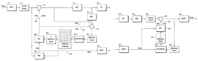
- FIG. 1 a is an encoder and FIG. 1 b is a decoder with which embodiments of the invention may be used.
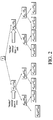
- FIG. 2 shows a representation of a three-level overcomplete DWT decomposition.
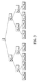
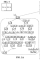
- FIG. 3 shows an example of the derivation of the subbands of the overcomplete wavelet transform of level 3 using the conventional LL-LBS method.
- a scalable coding framework only subbands A 0 3 ,D 0 3 are available at this level, since subbands D 0 2 and D 0 1 cannot be received by the decoders of this resolution.
- FIG. 4 shows an example of the derivation of the subbands of the Overcomplete Wavelet Transform of level 3 using a prediction-filter method in accordance with an embodiment of the invention.
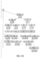
- FIG. 5 shown on two pages as FIGS. 5A and 5B , shows an Overcomplete DWT of k+1 levels starting from signal X .
- a “fictitious” pyramid that emerges from signal X fi is shown in the circled area.
- FIG. 6 shows a memory structure for the concurrent application of the L-tap filters U[n] and W[n] to the input sequence I[n] using a kernel with L multipliers according to an embodiment of the invention.
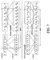
- FIG. 7 shows in the upper half the mirroring at the subband edges and the initiation and finalization of the inverse transform for level k ⁇ 1 that emerges from level k.
- the lower half shows the mirroring and initiation and finalization of the forward transform of level 1 that emerges from the reconstructed signal X.
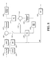
- FIG. 8 shows a wavelet video encoder according to an embodiment of the invention based on ‘bottom-up’ ODWT; motion estimation in spatial domain.
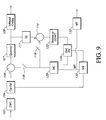
- FIG. 9 shows a wavelet video encoder according to an embodiment of the invention based on ‘bottom-up’ ODWT; motion estimation in wavelet domain.
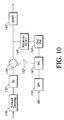
- FIG. 10 shows a wavelet video decoder in accordance with an embodiment of the invention based on ‘bottom-up’ ODWT.
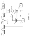
- FIG. 11 shows a wavelet video encoder in accordance with an embodiment of the invention based on ‘bottom-up’ MC; motion estimation in wavelet domain.
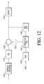
- FIG. 12 wavelet video decoder in accordance with an embodiment of the invention based on ‘bottom-up’ MC.
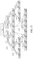
- FIG. 13 shows three wavelet decompositions for different translations T of the input signals X(z).
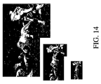
- FIG. 14 shows frame 5 of a football sequenve decomprtessed at 760 kps in different resolutions. From top to bottom: original size, half resolution and quarter resolution.
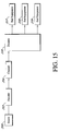
- FIG. 15 shows a schematic representation of a telecommunications system to which the invention may be applied.
- FIG. 16 shows a subband coding circuit in accordance with an embodiment of the invention.
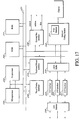
- FIG. 17 shows a further subband coding circuit in accordance with an embodiment of the invention.
- DWT Discrete Wavelet Transform
- SBC Subband Coder
- SBD Subband Decoder
- EC Entropy Coder
- CODWT Complete-to-Overcomplete DWT
- ME Motion Estimation
- MC Motion Compensation
- MVs Motion Vectors
- MVC Motion-Vector Coder
- IDWT Inverse DWT
- ED Entropy Decoder
- MVD Motion-Vector Decoder
- an original video image information stream is transformed into another digital representation.
- This digital representation may be stored on a suitable data carrier or transmitted to a remote location.
- the aim of coding is to provide an advantage, e.g., data compression and/or scalability of the data stream.
- the aim of decoding such an encoded signal is to reconstruct the original video information as economically and as well as possible, e.g., a lossless reconstruction.
- the arrays of pixels of such close frames often contain the same luminance and chrominance information except that the coordinates of pixel positions in the arrays are shifted or displaced. Shifting in position within the array is a function of time and defines a motion of these pixels within the arrays. The motion may be approximated by a motion vector.
- the encoding is based on the fact that at least parts of temporally close video frames either in the forward or backward direction are often quite similar except for motion. This similarity means that repeat transmission of this moving data in each frame is not required, it is only necessary to transmit a code of a shift of the data from a previous or subsequent frame, e.g., a motion vector.
- the motion used for motion estimation and compensation is a linear translation
- more complex motions or changes in pixel distributions can be considered as a basis for motion compensation and estimation.
- the invention includes within its scope alternative motion estimation and compensation models, e.g., linear translations, rotational translation of pixels, zooming of one part of an image compared to another.
- the model used may be generalized to say that there is a mapping between a part of one video frame and another video frame, this mapping being determined by predefined similarity criteria, that is the criteria which are to be used to determine that there is similarity between the parts of the two frames. This similarity may include linear translation, rotational translation, zooming between frames.
- the invention provides an approach for in-band ME/MC wherein prediction-filters are used.
- the algorithm can achieve mathematically the same result as the LBS algorithm of [14].
- the LBS algorithm is suitable for coding and/or encoding a bit stream comprising a representation of a sequence of n-dimensional data structures, in which n is typically 2 or 3, and where a part of the data of one data structure of the sequence maps within predefined similarity criteria to a part of the data of a another data structure of the sequence and is of the type which derives at least one further subband of an overcomplete representation from a complete subband transform of the data structures.
- FIG. 15 An example of a communication system 210 which can be used with the invention is shown in FIG. 15 . It comprises a source 200 of information, e.g., a source of video signals such as a video camera or retrieval from a memory.
- the signals are encoded in an encoder 202 resulting in a bit stream, e.g., a serial bit stream which is transmitted through a channel 204 , e.g., a cable network, a wireless network, an air interface, a public telephone network, a microwave link, a satellite link.
- the encoder 202 forms part of a transmitter or transceiver if both transmit and receive functions are provided.
- the received bit stream is then decoded in a decoder 206 which is part of a receiver or transceiver.
- the decoding of the signal may provide at least one of spatial scalablity, e.g., different resolutions of a video image are supplied to different end user equipments 207 - 209 such as video displays; temporal scalability, e.g., decoded signals with different frame rate/frame number ratios are supplied to different user equipments; and quality scalability, e.g., decoded signals with different signal to noise ratios are supplied to different user equipments.
- spatial scalablity e.g., different resolutions of a video image are supplied to different end user equipments 207 - 209 such as video displays
- temporal scalability e.g., decoded signals with different frame rate/frame number ratios are supplied to different user equipments
- quality scalability e.g., decoded signals with different signal to noise ratios are supplied to different user equipments.
- FIG. 1 A potential architecture of a wavelet-based video codec performing in-band motion estimation/motion compensation (ME/MC) with which a first embodiment of the invention may be used is given in FIG. 1 whereby FIG. 1 a shows the encoder and FIG. 1 b the decoder.
- This architecture can be seen as an extension of the “classical” architecture of transform-based video coders/decoders.
- this scheme there are two modes of operation as determined by the setting of the switches 16 , 18 , as explained in the following.
- the current input frame 4 is first of all wavelet transformed using a suitable compression technique such as the DWT module 2 of FIG.
- the resulting wavelet subbands are quantized and encoded using an embedded intra-band coding technique, (SBC module 8 ) and the result is entropy-coded using the EC module 10 .
- the embedded intra-band coding and the entropy coding are performed in a level-by-level fashion to guarantee resolution scalability. Furthermore, this process is performed until the target bit-rate for the currently coded frame is met.
- the second coding mode is the inter-frame coding mode, where each reference frame is first of all wavelet transformed using the DWT module 2 of FIG. 1 .
- the subbands of every decomposition level are encoded using the intra-band embedded coding technique in SBC module 8 and entropy-coded in EC module 10 .
- the SBD module 12 performs the decoding operation and produces the base quality layer of the reference frame, which is stored in a memory buffer 20 .
- the complete-to-overcomplete DWT module 22 (CODWT) produces, for each level, the set of one or more subbands of the overcomplete representation of the reference frame starting from the subbands of the critically sampled pyramid. These are stored in a buffer memory 24 .
- the resulting n subbands per level are then used during the motion estimation which is performed by the block-based ME module 30 to find the best match between the subband-information present in the current frame, received at module 30 from the output of DWT module 2 , and the overcomplete representation of the reference frame received from the buffer 24 .
- a block 26 is selected using selecting means in the motion compensation module 28 or the motion estimation module 30 from the buffered subbands of the reference frame that represents the best match is used for the motion-compensation process which is performed by the MC module 28 .
- the resulting motion-vectors of every decomposition level are sent to the motion-vector coder (MVC module 32 ).
- the output of the motion compensation is an error frame in the wavelet domain which is generated by subtracting the output of MC module 28 from the subband transformed current frame in subtractor 6 .
- This error frame is intra-band embedded coded in SBC module 8 and entropy-coded in EC module 10 in a level-by-level fashion.
- To generate the reference frame 20 from the subband decoded intra-band coded signal the output of SBD 12 is added to the output from MC 28 in adder 14 . This reference frame is used in the next iteration.
- the dashed line shows a less preferred embodiment in which the error frame is supplied directly to the adder 14 .
- the decoder operates exactly in the mirror fashion, the intra-frame or inter-frame decoding being determined by the switch 52 .
- the resolution-scalable coded frame is received and the bit-stream parsing can cease at any resolution or quality level (provided that the minimal base-quality layer is received).
- the next operations are entropy decoding in ED module 32 followed by subband decoding in SBD module 34 and inverse DWT in IDWT module 40 .
- the frame corresponding to the specific operational settings e.g., quality and resolution is reconstructed.
- the error-frame is received at the desired quality level at the ED module 32 and the corresponding motion vectors of each decomposition level are received and decoded as well by a MVD module 50 .
- the complete-to-overcomplete DWT of the reference frame 46 is constructed in a level-by-level manner in CODWT module 48 .
- the key difference is that since the motion vectors are known, only individual blocks 44 needed for the motion compensation which is to be performed in module 42 , are calculated by the CODWT module 48 . In the motion-compensation phase carried out in module 42 , these blocks 44 are used to reconstruct the predicted frame.
- the predicted frame is added to the error-frame 36 of the current decomposition level in adder 38 .
- the CODWT unit 48 operates on the base-quality layer for every decomposition level. Hence the decoder reconstructs the identical overcomplete representation per level as the encoder. In this manner, the decoder is free to stop decoding at any resolution or quality level.
- CODWT module 22 , 48 is a key part of the ME/MC subsystem of the scalable video-codec.
- FIG. 2 shows an example of the 1-D overcomplete pyramid for three decomposition levels as constructed by the LBS method.
- the input signal X is decomposed into two sets by retaining separately the even or odd polyphase components of the undecimated decomposition, or equivalently performing two “classical” wavelet decompositions; one in the zero-shifted input signal and one in the unit-shifted input.
- Each of the low-frequency subbands of the two decompositions is further analyzed into two sets by performing again an undecimated wavelet decomposition and retaining separately the even and odd polyphase components and so on.
- the 2-D overcomplete pyramid is constructed in the identical manner, with the application of the LBS method in the input-subband rows and the columns of the results.
- S 0 , S 1 denote the even and odd polyphase components of signal S respectively (named also type 0 and type 1 ).
- Each low-frequency (average) subband of decomposition level i is denoted as A x i , where x is a binary representation that shows the subband type, with the Most-Significant Bit (MSB) denoting the “Mother”—subband type and the Least-Significant Bit (LSB) denoting the current-subband type.
- MSB Most-Significant Bit
- LSB Least-Significant Bit
- subband A &011 3 denotes the low-frequency subband of level 3 that has been produced by retaining the even polyphase components of decomposition level 1 and the odd polyphase components of levels 2 and 3. Similar notations apply for the high-frequency (detail) subbands D x 1 .
- the LSB of the binary representation denotes a “turn” in the pyramid (0 for “left”, 1 for “right”) in comparison to the previous-level subband (“parent”).
- the subscript bits are shifted to the left and a new LSB is entered, depending on the polyphase grid that is retained from the decomposition (even, odd).
- the key-difference is that the subband-transmission and decoding occur in a bottom-up manner, every decoder receives the coarsest-resolution subbands first (i.e. subbands A 0 3 ,D 0 3 ) and is free to stop the bitstream-parsing at any time after the baseline quality-layer has been received for each level. In this way, the quality and resolution of the decoded video can vary accordingly.
- the LBS method is modified to perform a level-by-level construction of the overcomplete representation (denoted by LL-LBS), starting from the subbands of the critically-sampled transform of each coded level. Such a situation is illustrated in FIG.
- the low-frequency subbands A i k are constructed only if k is the coarsest-resolution level of the decomposition. In all the other cases, only the high-frequency subbands D j k , with j ⁇ [1,2 k ⁇ 1], j ⁇ Z are needed. This is imposed by the fact that no motion estimation or compensation is performed for the subband A 0 k if k is not the coarsest decomposition level. Hence, in the example if after the construction of the overcomplete transform of level 3, one more resolution level is received (i.e.
- the LL-LBS operates again in the same fashion, but constructs only the subbands D j 2 , with j ⁇ [1, 3], j ⁇ Z.
- approximations of the subbands D j 2 can already be calculated during the calculations of level 3, at this time the subband D 0 2 is not available; as a consequence, these approximations are obtained based only on the subband A 0 2 and hence they do not have the best accuracy possible.
- This observation indicates a significant difference between the LL-LBS and the LBS methods: because of the bottom-up level-by-level construction, the high-frequency subbands of the higher-resolution levels (levels 2 and 1 in the example) are not available when the current level is processed (level 3).
- the resulting overcomplete representation of each level obtained with the LL-LBS method is not identical to the one constructed with the LBS algorithm.
- the LBS algorithm creates the overcomplete representation under the assumption that all the subbands of the critically sampled pyramid are available, and this is not always the case in a resolution-scalable framework.
- the LBS method requires the receipt of all resolutions in order to create the overcomplete representation.
- all resolutions should be available.
- the level-by-level LBS produces the subbands of the overcomplete representation with the best accuracy possible while simultaneously ensuring drift-free, full resolution-progressive decoding (i.e. spatial scalability).
- the overcomplete representation can be obtained by the application of prediction filters.
- An example of the derivation of the subbands of level 3 with the prediction-filters method is given in FIG. 4 . It can be noticed that the overcomplete representation is “predicted” in a level-by-level manner using the sets of filters F R Q , with Q ⁇ [1,3],Q ⁇ Z and R ⁇ [0,15],R ⁇ Z indicated under the subband-pairs of FIG. 4 .
- no upsampling or downsampling is performed with this algorithm and this leads to substantial complexity reductions.
- the overcomplete pyramid is separated into the “left-half” and “right-half” pyramids respectively. These parts correspond to the two “Mother” subbands containing the even and odd-polyphase components respectively of the undecimated decomposition of the original signal.
- H(z), A 4 3 (z), F 2 1 (z) are simply denoted as H ,A 4 3 ,F 2 1 respectively, to reduce the expressions' length, while (H) 0 ,(H) 1 denote the even or odd polyphase components (similar applies for H i,0 ,H i,1 for filter H i ).
- level-by-level overcomplete transform of level k is readily extracted as a special case, in which the overcomplete subbands are calculated using only the critically-sampled representation of the same level.
- the symmetry properties of the prediction filters for every decomposition level are given, which allow their efficient implementation.
- i(m) are filter indices defined as i(m)
- i(m) are filter indices given by i(m)
- F 0 1 Det ⁇ 1 ( H 1 G 1 ⁇ zH 0 G 0 )
- F 1 1 Det ⁇ 1 ( zH 0 H 0 ⁇ H 1 H 1 )
- F 2 1 Det ⁇ 1 ( G 1 G 1 ⁇ zG 0 G 0 )
- F 3 1 Det ⁇ 1 ( zH 0 G 0 ⁇ H 1 G 1 )
- Det is the determinant of the analysis polyphase matrix H p (z), given by:
- H _ p ⁇ ( z ) ( H 0 ⁇ ( z ) H 1 ⁇ ( z ) G 0 ⁇ ( z ) G 1 ⁇ ( z ) ) , ( 19 )
- equations (21)-(22) By performing the transformations of variables specified by equation (20), equations (21)-(22) become:
- a 0 k z ⁇ [ H ⁇ ⁇ ( z ) ⁇ A 0 k + 1 ⁇ ( z 2 ) + G ⁇ ⁇ ( z ) ⁇ D 0 k + 1 ⁇ ( z 2 ) ] . ( 26 ) Since both A 0 k and D 0 k subbands are known now, we can apply any of the propositions of level k (involving the F i k filters), since they are true by assumption. Hence, we can calculate any subband A x k , with x ⁇ [2 k ⁇ 1 ,2 k ⁇ 1] by using the set of propositions P R (k) given in equation (8). By replacing (26) in (8) we obtain:
- a x k ⁇ ( z ) zF 4 ⁇ p k ⁇ ( z ) ⁇ H ⁇ ⁇ ( z ) ⁇ A 0 k + 1 ⁇ ( z 2 ) + ⁇ zF 4 ⁇ p k ⁇ ( z ) ⁇ G ⁇ ⁇ ( z ) ⁇ D 0 k + 1 ⁇ ( z 2 ) + F 4 ⁇ p + 1 k ⁇ ( z ) ⁇ D 0 k ⁇ ( z ) + T ⁇ ( k - 1 , z ) , ⁇ ( 27 ) with:
- T ⁇ ( k - 1 , z ) ( H ⁇ F i ⁇ ( 1 ) k - 1 ⁇ D 0 k - 1 ) b 0 + [ H ⁇ ( H ⁇ F i ⁇ ( 2 ) k - 2 ⁇ D 0 k - 2 ) b i ] b 0 + ... + [ H ⁇ ( H ⁇ ( ... ⁇ ( H ⁇ F i ⁇ ( k - 1 ) 1 ⁇ D 0 1 ) b k - 2 ) b k - 3 ⁇ ... ) b i ] b 0 , ( 28 ) and b i , i(m) defined as for equation (8).
- the “tail” T(k ⁇ 1,z) denotes the contributions of levels 1,2, . . . , k ⁇ 1.
- a x k ⁇ ( z 1 2 ) z 1 2 ⁇ F 4 ⁇ p k ⁇ ( z 1 2 ) ⁇ H ⁇ ⁇ ( z 1 2 ) ⁇ A 0 k + 1 ⁇ ( z ) + z 1 2 ⁇ F 4 ⁇ p k ⁇ ( z 1 2 ) ⁇ G ⁇ ⁇ ( z 1 2 ) ⁇ D 0 k + 1 ⁇ ( z ) + F 4 ⁇ p + 1 k ⁇ ( z 1 2 ) ⁇ D 0 k ⁇ ( z 1 2 ) + T ⁇ ( k - 1 , z 1 2 ) ( 30 )
- a x k ⁇ ( z 1 2 ) z 1 2 ⁇ ( F 4 ⁇ p , 0 k + z - 1 2 ⁇ F 4 ⁇ p , 1 k ) ⁇ ( G 0 - z - 1 2 ⁇ G 1 ) ⁇ A 0 k + 1 + z 1 2 ⁇ ( F 4 ⁇ p , 0 k + z - 1 2 ⁇ F 4 ⁇ p , 1 k ) ⁇ ( - H 0 + z - 1 2 ⁇ H 1 ) ⁇ D 0 k + 1 + T ⁇ ( k , z 1 2 ) , ( 37 ) where
- T ⁇ ( k , z 1 2 ) F 4 ⁇ p + 1 k ⁇ ( z 1 2 ) ⁇ D 0 k ⁇ ( z 1 2 ) + T ⁇ ( k - 1 , z 1 2 ) , ( 38 ) is the “‘tail’” that includes the contribution of level k.
- a x k ⁇ ( z 1 2 ) [ ( z 1 2 ⁇ G 0 - G 1 ) ⁇ F 4 ⁇ p , 0 k + ( G 0 - z - 1 2 ⁇ G 1 ) ⁇ F 4 ⁇ p , 1 k ] ⁇ A 0 k + 1 + [ ( H 1 - z 1 2 ⁇ H 0 ) ⁇ F 4 ⁇ p , 0 k + ( z - 1 2 ⁇ H 1 - H 0 ) ⁇ F 4 ⁇ p , 1 k ] ⁇ D 0 k + 1 + T ⁇ ( k , z 1 2 ) ( 39 )
- a x k ⁇ ( z 1 2 ) L k + 1 + A ⁇ A 0 k + 1 + L k + 1 + D ⁇ D 0 k + 1 + T ⁇ ( k , z 1 2 ) . ( 42 ) Similarly as above, we can calculate A x k ( ⁇ z 1/2 ) by replacing z with ( ⁇ z 1/2 ) in equation (27):
- a x k ⁇ ( - z 1 2 ) - z 1 2 ⁇ F 4 ⁇ p k ⁇ ( - z 1 2 ) ⁇ H ⁇ ⁇ ( - z 1 2 ) ⁇ A 0 k + 1 ⁇ ( z ) - z 1 2 ⁇ F 4 ⁇ p k ⁇ ( - z 1 2 ) ⁇ G ⁇ ⁇ ( - z 1 2 ) ⁇ D 0 k + 1 ⁇ ( z ) + F 4 ⁇ p + 1 k ⁇ ( - z 1 2 ) ⁇ D 0 k ⁇ ( - z 1 2 ) + T ⁇ ( k - 1 , - z 1 2 ) ( 43 )
- a x k ⁇ ( - z 1 2 ) [ ( - z 1 2 ⁇ G 0 - G 1 ) ⁇ F 4 ⁇ p , 0 k + ( G 0 + z - 1 2 ⁇ G 1 ) ⁇ F 4 ⁇ p , 1 k ] ⁇ A 0 k + 1 + [ ( H 1 + z 1 2 ⁇ H 0 ) ⁇ F 4 ⁇ p , 0 k ] + ( - z - 1 2 ⁇ H 1 - H 0 ) ⁇ F 4 ⁇ p , 1 k ] ⁇ D 0 k + 1 + T ⁇ ( k , - z 1 2 ) ( 50 )
- a x k ⁇ ( - z 1 / 2 ) L k + 1 - A ⁇ A 0 k + 1 + L k + 1 - D ⁇ D 0 k + 1 + T ⁇ ( k , - z 1 / 2 ) .
- [ A 2 ⁇ x k + 1 D 2 ⁇ x k + 1 ] 1 2 ⁇ [ H 0 ⁇ ( z ) + z - 1 / 2 ⁇ H 1 ⁇ ( z ) H 0 ⁇ ( z ) - z - 1 / 2 ⁇ H 1 ⁇ ( z ) G 0 ⁇ ( z ) + z - 1 / 2 ⁇ G 1 ⁇ ( z ) G 0 ⁇ ( z ) - z - 1 / 2 ⁇ G 1 ⁇ ( z ) ] ⁇ [ L k + 1 + A ⁇ A 0 k + 1 + L k + 1 + D ⁇ D 0 k + 1 + T ⁇ ( k , z 1 / 2 ) L k + 1 - A ⁇ A 0 k + 1 + L k + 1 - D ⁇ D 0 k + 1 + T ⁇ ( k , z 1 /
- a 2 ⁇ x k + 1 , D 2 ⁇ x k + 1 consists of separate calculations of factors like
- a y k + 1 F 4 ⁇ q k + 1 ⁇ A 0 k + 1 + F 4 ⁇ q + 1 k + 1 ⁇ D 0 k + 1 + [ H ⁇ F 4 ⁇ ⁇ q 2 ⁇ + 1 k ⁇ D 0 k ] c 0 + [ H ⁇ ( H ⁇ F j ⁇ ( 2 ) k - 1 ⁇ D 0 k - 1 ) c 1 ] c 0 + [ H ⁇ ( H ⁇ ( H ⁇ F j ⁇ ( 3 ) k - 2 ⁇ D 0 k - 2 ) c 2 ) c 1 ] c 0 + ... ++ ⁇ [ H ⁇ ( H ⁇ ( ... ⁇ ( H ⁇ F j ⁇ ( k ) 1 ⁇ D 0 1 ) c k - 1 ) c k - 2 ⁇ ... ) c 1 ] c 0 ,
- D y k + 1 F 4 ⁇ q + 2 k + 1 ⁇ A 0 k + 1 + F 4 ⁇ q + 3 k + 1 ⁇ D 0 k + 1 + [ G ⁇ F 4 ⁇ ⁇ q 2 ⁇ + 1 k ⁇ D 0 k ] c 0 + [ G ⁇ ( H ⁇ F j ⁇ ( 2 ) k - 1 ⁇ D 0 k - 1 ) c 1 ] c 0 + [ G ⁇ ( H ⁇ ( H ⁇ F j ⁇ ( 3 ) k - 2 ⁇ D 0 k - 2 ) c 2 ) c 1 ] c 0 + ... ++ ⁇ [ G ⁇ ( H ⁇ ( ... ⁇ ( H ⁇ F j ⁇ ( k ) 1 ⁇ D 0 1 ) c k - 1 ) c k - 2 ⁇ ... ) c 1 ] c 0
- Equations (65), (66) are equivalent to equations (25) for the even values of x (even-numbered subbands). Hence, in this case the propositions P R (k+1) are true.
- the proof of P R (k+1) for odd values of x is done in a similar manner. In order to calculate the subbands
- a 2 ⁇ x + 1 k + 1 , D 2 ⁇ x + 1 k + 1 consists of separate calculations of factors like
- equations (73) and (74) as follows:
- a y k + 1 F 4 ⁇ q k + 1 ⁇ A 0 k + 1 ⁇ F 4 ⁇ q + 1 k + 1 ⁇ D 0 k + 1 + ( H ⁇ F 4 ⁇ ⁇ q 2 ⁇ + 1 k ⁇ D 0 k ) c o + [ H ⁇ ( H ⁇ F j ⁇ ( 2 ) k - 1 ⁇ D 0 k - 1 ) c i ] c o + [ H ( H ⁇ ( H ⁇ F j ⁇ ( 3 ) k - 2 ⁇ D 0 k - 2 ) c2 ) c i ] c o + ⁇ ++ ( 79 ) [ H ⁇ ( H ⁇ ( ...
- Equations (79), (80) are equivalent with equations (25) for the odd values of x (odd-numbered subbands) Hence the propositions P R (k+1) are true in this case too.
- equations (65), (66) with (79), (80) we derive the set of propositions P R (k+1) of level k+1, for any values of x.
- Equations (115), (121), (126) (131) can be derived from equations (89)-(92) by replacing k with k+1 Thus the symmetry propositions P S (k+1) are true. This end the proof of the induction, that is the symmetry propositions P S (E) are true for any level E, with E>1.
- the level-by-level calculation of the overcomplete representation from the critically-sampled pyramid can be performed by using two techniques: the LL-LBS method described above and the prediction-filters method in accordance with the invention.
- Each technique operates in two modes depending on the current decomposition level.
- the first mode is the full-overcomplete (FO) transform-production mode, where the current decomposition level is the coarsest-resolution representation, therefore the low and the high-frequency subbands are produced (level 3 in the particular example of FIG. 3 ).
- the second is the high-frequency overcomplete (HFO) transform-production mode, where the current decomposition level is an intermediate-resolution level, and as a consequence, only the high-frequency subbands of this resolution need to be computed.
- FO full-overcomplete
- HFO high-frequency overcomplete
- the first is the necessary number of multiplication operations, which corresponds to the computational complexity of each method, since multiplication is the dominant operation in convolutional systems.
- the second is the delay for the production of the results of every level, which can be estimated under some assumptions concerning the degree of parallelism achievable in the implementation of every technique. Since systems with a high degree of parallelism are assumed and designs with the minimum amount of multiplications are chosen for both methods, the results of this section are more realistic for custom-hardware rather than processor-based solutions; in the latter, a lower level of parallelism is feasible and the minimization of MAC operations is the critical issue in the complexity reduction.
- X C (N), ⁇ C (N) denote the number of multiplications needed to perform a complete decomposition and reconstruction of N samples respectively.
- the required number of multiplications for an N-sample signal is:
- a 2 ⁇ i L + 2 l + 1 k ⁇ [ n ] F 8 ⁇ i L + 4 l + 1 ⁇ [ n ] * A 0 k ⁇ [ n ] + F 8 ⁇ i L + 5 l + 1 ⁇ [ n ] * D
- Equations (141), (142) and (143) represent the calculation of the “left-half” and “right-half” of the overcomplete pyramid as seen from FIG. 5 . Notice that each of the two subbands A 0 k ,D 0 k contains
- the total calculation budget can be reduced if instead of performing directly the convolutions in (142) and (143) with the filters
- equation (144) is modified to:
- a memory structure can be utilized to delay the intermediate results of the convolution in the time domain for the parallel calculation of U[n]*I[n] and W[n]*I[n].
- U[n] For an L-tap filter U[n], such a memory structure is shown in FIG. 6 . Similar forms are commonly utilized for the efficient realization of FIR orthogonal filter-banks. Using such memory structures for the parallel application of the prediction filters, the required number of multiplications can be reduced by half, for every set of prediction filters F 1 l . This can be seen from the example of FIG.
- the convolutions with filters F 0 3 ,F 1 3 ,F 2 3 ,F 3 3 and F 8 3 , F 9 3 , F 10 3 , F 11 3 can provide the results of filtering with F 12 3 ,F 13 3 ,F 14 3 , F 15 3 and F 4 3 ,F 5 3 ,F 6 3 ,F 7 3 respectively.
- F 8 ⁇ i k ⁇ ( z - 1 ) F 4 ⁇ i , 0 k - 1 ⁇ ( z - 1 ) - z ⁇ ⁇ F 3 1 ⁇ ( z - 1 ) ⁇ F 4 ⁇ i , 1 k - 1 ⁇ ( z - 1 ) , ( 146 )
- F 8 ⁇ i + 1 k ⁇ ( z - 1 ) z ⁇ ⁇ F 1 1 ⁇ ( z - 1 ) ⁇ F 4 ⁇ i , 1 k - 1 ⁇ ( z - 1 ) , ( 147 )
- F 8 ⁇ i + 2 k ⁇ ( z - 1 ) z ⁇ ⁇ F 2 1 ⁇ ( z - 1 ) ⁇ F 4 ⁇ i , 1 k - 1 ⁇ ( z - 1 ) , ( 148 )
- any convolution with filters F 0 1 (z ⁇ 1 ),F 1 1 (z ⁇ 1 ),F 2 1 (z ⁇ 1 ),F 3 1 (z ⁇ 1 ) is equivalent to the convolution with F 0 1 , F 1 1 ,F 2 1 ,F 3 1 (with the appropriate delays).
- all the filter-applications shown in the time-inversed update-structure of (146)-(153) can be implemented by the convolutions shown in Table V and a number of memory structures such as the one shown in FIG. 6 ; hence the update-structure implementation can provide the convolutions with the time-inversed filters with no additional arithmetic operations.
- the numbers of multiplications shown in parenthesis correspond to an approximation of the prediction filters where, for the filters of the update structure of every level, all taps smaller than a threshold are set to zero. In this way, the size of the filters of each level is reduced, while a good approximation of the final result is obtained.
- This technique cannot be applied in the LL-LBS approach since the taps of the biorthogonal filter-pairs do not have magnitudes below the chosen thresholds.
- Table VIII shows the values used for the thresholds and the resulting maximum mean-square error (MMSE) between the results obtained with the original and thresholded prediction filters when applied in the 2-D (row-column) manner to the 8-bit images of the JPEG-2000 test-set. It can be observed from the MMSE values that the chosen method for thresholding has a minimal effect on the results of the prediction filters while it reduces significantly the computational load.
- the delay resulting from the storage or retrieval of intermediate results is not taken into account.
- the delay for the calculations in the FO mode is equivalent to the one for the HFO mode, with the latter requiring less filter-kernels.
- the LL-LBS method Starting from the subbands A 0 k ,D 0 k , the LL-LBS method performs k inverse transforms and
- the cascade initiation of each of the inverse transforms at levels k ⁇ 1,k ⁇ 2, . . . , 1 requires
- the convolutions with the filters F 0 2 ,F 1 2 ,F 2 2 ,F 3 2 can be initiated in parallel for the calculation of the subbands A 1 k , D 1 k .
- the filters that produce the rest of the subbands of level k can also be applied in parallel using the update-structure implementation.
- the application of all these filter-kernels will occur as soon as enough coefficients from the sequences [F 0 1 [n]*A 0 k [n]], [F 1 1 [n]*D 0 k [n]], [F 2 1 [n]*A 0 k [n]], [F 3 1 [n]*D 0 k [n]] are calculated, so that the necessary mirroring in the update structure can be performed.
- a delay equal to the maximum filter-length is required so that the calculations of the subbands that are produced by the time-inversed impulse responses are initiated as well by the memory structures.
- the latency for the initiation of all the convolutions is:
- P - Filters ⁇ ( k ) a PF ⁇ ( ⁇ max ⁇ ⁇ T F i , 0 l , T F i , 1 l , T F j l ⁇ + 1 2 ⁇ + max ⁇ ⁇ T F i , 0 l , T F i , 1 l , T F j l ⁇ ) , ( 158 ) with l ⁇ [2,k ⁇ 1],i ⁇ [0,2 l ⁇ 2 ⁇ 1],j ⁇ [0,3]. Then, the delay for the completion of the process is simply:
- the 2-D extension of the LL-LBS and the prediction-filters method can be intuitively performed by extending the 1-D application to a separate application to the rows of the input subbands and to the columns of the produced results.
- Such extensions are due to the separability property of the DWT.
- the separable row and column application leads to the same computational gains for the prediction-filters method in comparison to the LL-LBS approach as in the 1-D case.
- the delay of every method when applied in two dimensions is dependent on the level of parallelism for each system.
- the prediction filters method requires only the application of a set of filters in the row and column directions, under any practically-applicable level of parallelism, this method is expected to achieve a much lower delay for the production of the 2-D overcomplete transform than the 2-D LL-LBS method, which consists of a cascaded multirate filter-bank implementation.
- every method can be implemented by two separate systems: one for the row and one for the column processing.
- the delay for the production of the results is simply the delay for the completion of the row-by-row filtering plus the delay for the completion of the columns' processing with the results of the last row.
- the column processing begins after an initiation latency so that enough coefficients exist columnwise for the mirroring and for the initiation of the filter-applications required for every method. Since the process is separable, the initiation latency is equivalent to the one of the 1-D case. Hence, for the LL-LBS method, the required processing-cycles are:
- the prediction-filters system possesses a simple implementation structure, since it consists of the parallel application of a set of filters to the same input (single-rate), while the LL-LBS approach requires precise control on the data-flow in the multirate implementation-structure in order to achieve a high-parallel system.
- the selective construction of specific blocks of the various subbands of the overcomplete transform in the decoder is expected to be much easier in the prediction-filters system than in the conventional LL-LBS approach.
- the ‘bottom-up’ ODWT (overcomplete discrete wavelet transform), based on the in-band motion compensation methods described above, can be used in a wavelet video encoder in the following way (see FIGS. 8 and 9 ).
- the wavelet video encoder has the in-band structure, which means that motion compensation (MC) performed in the motion compensation module 128 is performed in the wavelet domain.
- the motion vectors (MV) 132 provided by a motion estimation (ME) algorithm (e.g., block-based) carried out in the motion estimation module 130 , are preferably given with highest possible accuracy and are either estimated in the spatial (see embodiment of FIG. 8 ) or in the wavelet domain (see embodiment of FIG. 9 ).
- the ‘bottom-up’ ODWT module 122 takes as input the reconstructed reference wavelet subband image after the inverse quantization IQ in IQ module 111 and summation in summer 114 .
- the overcomplete representation generated by application of a digital filter is stored in a memory buffer (Oref FM) 124 .
- the motion compensation process carried out in the motion compensation module 128 takes as input the motion vectors and this overcomplete representation. Depending on the motion vectors, blocks of coefficients are selected using a selection means in the motion compensation unit 128 from the overcomplete representation. These coefficients are combined into a wavelet decomposition that is a prediction of the wavelet decomposition of the current image of the video sequence.
- This prediction is subtracted from the wavelet decomposition of the current image in subtracter 106 resulting in a wavelet subband error image.
- This subband error image is subsequently quantized in quantizer 107 and coded in subband coder 108 .
- the subband error image is also inversely quantized in IQ module 111 and added to the previous prediction from the MC module 128 in adder 114 in order to obtain the next reconstructed reference wavelet subband image to be used by the ‘bottom-up’ ODWT module 122 in the following iteration.
- FIGS. 8 and 9 The main difference between FIGS. 8 and 9 is that in FIG. 8 the motion estimation is carried out in the spatial domain whereas in FIG. 9 these vectors are determined in the wavelet domain.
- the motion vectors are supplied to the motion compensation module and the receiver from the motion estimation module 130 .
- a selection means in MC module 128 selects the most appropriate subbands, e.g., block subbands, from the overcomplete representation in buffer 124 .
- FIG. 9 the motion estimation is made using the subbands of the overcomplete representation stored in buffer 124 . This motion cestimation can be made level-by-level.
- the wavelet video decoder (see FIG. 10 , having modules common to both embodiments of FIGS. 8 and 9 ) operates in an analogous way.
- the input for the subband decoder module 134 is the quantized and coded wavelet subband error image.
- the decoded error image is supplied to the inverse quantizer 135 which ouputs an inversely quantized subband error image which is summated in the summer 138 with the predicted wavelet subband image originating from the motion compensation module 142 . This results in the reconstruction of the current wavelet subband image of the video sequence, which will subsequently be reconstructed by the IDWT (inverse DWT) module 140 .
- IDWT inverse DWT
- the reconstructed wavelet subband image is also the input for the ‘bottom-up’ ODWT module 148 that generates the overcomplete representation to be stored into the memory buffer (Oref FM), e.g., using application of predictor digital filters as described above. Then the motion compensation module 142 selects wavelet coefficients from this overcomplete representation based on the decoded motion vectors 150 . These wavelet coefficients are combined into a wavelet decomposition that is a prediction of the current wavelet subband image of the video sequence. This prediction will be summated to the decoded and inversely quantized wavelet subband error image in the following iteration in summer 138 . Note that the switches 116 , 118 ; 152 in both the encoders of FIGS.
- the decoder of FIG. 10 respectively provide either the intra (open switch) or the inter (closed switch) encoding/decoding state.
- the text above is a description of the inter encoding/decoding state.
- a full wavelet subband image is processed instead of a subband error image.
- the proposed coding scheme with motion estimation in the wavelet domain can be applied to the encoder shown in FIG. 1 a .
- the operation shows a hybrid coding structure; thus when coding in intra-frame mode, the current frame is wavelet decomposed (DWT module 2 ) and compressed with a block-based intra-band coder (SBC module 8 ). This intra-compressed frame is decompressed (SBD module 12 ) and the reconstructed wavelet decomposition is used by the CODWT module 22 .
- This module 22 operates in a subband-by-subband manner and constructs from the critically-sampled decomposition of every level, the overcomplete transform of that level, which contains all the subband information that is missing from the critically sampled pyramid due to the subsampling operations of every level.
- An important feature of the invention is that for this operation, methods of the invention provide fast calculation-algorithms with identical algorithmic performance to LBS. These calculations include digital filters.
- the overcomplete representation is used for in-band motion estimation since it is shift invariant.
- the motion compensation is performed in module 28 in the critically-sampled pyramid, which is subsequently subtracted from the current frame and coded (error frame) in the subtractor 6 .
- the decoder operates in a similar manner as seen from the lower part of FIG.
- FIG. 14 shows an example of frame 5 decompressed at various resolutions with the proposed scheme.
- the sequence was compressed once and all the presented results where achieved by simply decompressing to various bit-rates and resolutions. The conclusion is that the approach provides resolution, quality and temporal scalability in video compression with the hybrid-coding structure if the in-band approach is adopted.
- the hybrid in-band (motion estimation and compensation in the transform domain) approach using overcomplete representations equipped with the fast calculation methods can decode to a variety of bit-rates and resolutions achieving at the same time very competitive performance to state of the art 3-D wavelet video-coding and coding standards, which are often proposed in the literature as the best solution for fine granularity scalability in video compression.
- wavelet video encoders and decoder based on the in-band motion compensation theory exploiting the in-band motion compensation theory based prediction rules are disclosed.
- the wavelet coefficients required by the motion compensation process can directly be calculated from the reference wavelet subband image without the need for calculating all of the subbands of an overcomplete representation. Instead, only those subbands are calculated as required, whereby these subbands can belong to the set of subbands of the overcomplete representation.
- the propositions in the in-band motion compensation theory provide the required motion compensating prediction rules that correspond to all possible translations. These prediction rules make use of prediction filters and of particular subbands of the reference wavelet subband image. Which prediction filters to use and which subbands to choose, is determined by the motion vectors.
- the motion estimation process is block-based, then the prediction rules only take as input blocks of wavelet coefficients from the reference wavelet subband image. Hence, this ‘bottom-up’ motion compensation process does not require the computation of a total overcomplete representation, but calculates the required wavelet coefficients directly on a block-by-block basis.
- a wavelet video encoder is shown schematically in FIG. 11 and the decoder in FIG. 12 .
- the motion compensation module 128 uses the motion vector information obtained from the motion estimation module 130 to calculate only the best subbands for motion compensation.
- the method of calculation relies on digital predictor filters as described above but avoids the requirement to calculate all the subbands of the overcomplete representation.
- FIG. 11 motion estimation is performed in the wavelet domain, but it can also be performed in the spatial domain as in FIG. 8 .
- resolution scalable wavelet video encoders and decoders based on the in-band motion compensation theory are disclosed.
- the wavelet video codecs are both capable of supporting resolution scalability while avoiding a drift between the encoder and the decoders of different resolution levels.
- a spatial domain motion compensation encoder causes a drift between what is encoded at full resolution and what is being decoded at a lower resolution. The reason for this drift is that the encoder uses all information available in the full resolution image (all subbands), which is not all transmitted to the decoders.
- a solution would be to code every resolution level independently from each other so that all possible configurations of decoders are supported, i.e. multicasting. Multicasting is however very inefficient from the encoders point of view, because multiple encoded streams have to be generated.
- the advantage of the wavelet transform is that it is critically sampled and supports multiple resolution scales. This is in contrast to the layered approach, where the total number of coded ‘coefficients’ is higher than the number of pixels of the full resolution image. Hence, an improved coding efficiency can be expected from the hierarchical coding approach.
- motion compensation should be performed in the transform domain to make full advantage of the hierarchical resolution property of the wavelet transform for video coding, hence the wavelet video codec structures of FIGS. 8 and 11 , respectively are required.
- a simple precaution needs to be taken.
- subbands of lower wavelet levels should not be used in the motion compensation process (lower wavelet level corresponds to higher resolution level).
- lower wavelet level corresponds to higher resolution level.
- a decoder for this particular resolution level does not receive the information that corresponds to the subbands of the lower wavelet levels and hence can not use it.
- the propositions or prediction rules of the in-band motion compensation theory should be adjusted. Terms in these prediction rules, which correspond to lower wavelet level subbands, should be neglected to enable resolution scalability by the wavelet video encoders of the first two embodiments.
- a method for wavelet-based in-band motion compensation and a digital, being useful for the first four embodiments is disclosed.
- a novel in-band motion compensation method for wavelet-based video coding is proposed, derived here for the 1-D discrete wavelet transform but not limited thereto.
- the fundamental idea is the computation of the relationships between the subbands of the non-shifted input signal and the subbands corresponding to all translations of the input signal.
- the motion compensation method is formalized into prediction rules.
- the in-band motion compensation algorithm can be extended to 2-D images, decomposed using the separable 2-D WT.
- the chosen approach is valid for N-level decompositions.
- the prediction rules of the algorithm allow the in-band motion compensation process to reach a zero prediction error for all translations of the image pixels.
- other applications are envisaged such as in-band motion estimation, overcomplete wavelet decompositions, etc.
- the discrete wavelet transform is inherently scalable in resolution and quality, which is a very much wanted property for streaming video e.g., on the Internet.
- a possible codec structure exploiting the WT for video coding is the in-band codec. In-band means that motion compensation is performed on the wavelet coefficients.
- the novel motion compensation algorithm or method will be derived for the 1-D WT.
- Y(z) the result of filtering the input signal X(z) with filter H(z).
- Y even (z) and Y odd (z) In general, only a limited number of possible delayed outputs exist, equal to the subsampling factor M. Therefore, this system is called periodic translation-invariant.
- Level 1 is derived.
- Y even (z) or Y odd (z) we obtain a shifted version of either Y even (z) or Y odd (z).
- motion compensation can be simplified to prediction of odd samples from even samples or vice versa.
- a even (z) we denote respectively the average subband by A even (z), and the detail subband by D even (z).
- z k A even (z) we denote respectively the average subband by A even (z), and the detail subband by D even (z).
- level 1 represents a decomposition tree containing the subbands of the single level WT for different translations ⁇ . Without any loss of generality one can drop the delays z k , and one can reduce the in-band motion compensation problem to predicting the subbands A odd (z) and D odd (z) from the reference subbands A even (z) and D even (z). This results in the first prediction rule:
- the following prediction rules can be formulated:
- P 2,0 (z) and P 2,1 (z) are the polyphase components of
- P 2 ⁇ ( z ) ⁇ ; ⁇ ( A ⁇ / ⁇ D ) even P 3 ⁇ ( z ) ⁇ D even ( z ) ⁇ ( z ) is the filtered and subsampled signal, originating from P 3 (z)D even (z) by respectively filtering with H(z) or G(z), and retaining the even samples.
- a even A even A odd ⁇ ( z ) R 0 ⁇ ( z ) ⁇ A even A even A even ⁇ ( z ) + R 1 ⁇ ( z ) ⁇ D even A even A even ⁇ ( z ) + z - 1 ⁇ A odd z ⁇ ⁇ Q 1 ⁇ ( z ) ⁇ D even A even ⁇ ( z ) + A even A even P 3 ⁇ ( z ) ⁇ D even ⁇ ( z ) , ⁇ ( 194 )
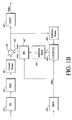
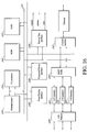
- FIG. 16 shows the implementation of a coder/decoder which can be used with the invention implemented using a microprocessor 230 such as a Pentium IV from Intel Corp. USA.
- the microprocessor 230 may have an optional element such as a co-processor 224 , e.g., for arithmetic operations or microprocessor 230 - 224 may be a bit-sliced processor.
- a RAM memory 222 may be provided, e.g., DRAM.
- I/O (input/output) interfaces 225 , 226 , 227 may be provided, e.g., UART, USB, I 2 C bus interface as well as an I/O selector 228 .
- FIFO buffers 232 may be used to decouple the processor 230 from data transfer through these interfaces.
- a keyboard and mouse interface 234 will usually be provided as well as a visual display unit interface 236 .
- Access to an external memory such as a disk drive may be provided via an external bus interface 238 with address, data and control busses.
- the various blocks of the circuit are linked by suitable busses 231 .
- the interface to the channel is provided by block 242 which can handle the encoded video frames as well as transmitting to and receiving from the channel. Encoded data received by block 242 is passed to the processor 230 for processing.
- this circuit may be constructed as a VLSI chip around an embedded microprocessor 230 such as an ARM7TDMI core designed by ARM Ltd., UK which may be synthesized onto a single chip with the other components shown.
- a zero wait state SRAM memory 222 may be provided on-chip as well as a cache memory 224 .
- Various I/O (input/output) interfaces 225 , 226 , 227 may be provided, e.g., UART, USB, I 2 C bus interface as well as an I/O selector 228 .
- FIFO buffers 232 may be used to decouple the processor 230 from data transfer through these interfaces.
- a counter/timer block 234 may be provided as well as an interrupt controller 236 .
- Access to an external memory may be provided an external bus interface 238 with address, data and control busses.
- the various blocks of the circuit are linked by suitable busses 231 .
- the interface to the channel is provided by block 242 which can handle the encoded video frames as well as transmitting to and receiving from the channel. Encoded data received by block 242 is passed to the processor 230 for processing.
- Software programs may be stored in an internal ROM (read only memory) 246 which may include software programs for carrying out subband decoding and/or encoding in accordance with any of the methods of the invention.
- software programs may be provided for digital filters according to embodiments of the invention described above to be applied to a reference or other frame of data to generate one or more subbands of a set of subbands of an overcomplete representation of the frame by calculations at single rate. That is the software, when executed on the processor 230 carries out the function of any of the modules 22 , 122 , 48 , 148 , 128 , 142 described above.
- Software may also combine the functions of several modules, e.g., the module 30 and module 22 of FIG. 1 a or the module 130 and module 122 of FIG.
- modules 22 , 28 and 30 of FIG. 1 a or modules 122 , 128 , 130 of FIGS. 8 , 9 or 11 or modules 122 and 128 of FIG. 8 or modules 128 and 130 of FIG. 11 or modules 142 and 148 of FIG. 10 may be written as computer programs in a suitable computer language such as C and then compiled for the specific processor in the design.
- a suitable computer language such as C
- the software may be written in C and then compiled using the ARM C compiler and the ARM assembler.
- the invention also includes a data carrier on which is stored executable code segments, which when executed on a processor such as 230 will execute any of the methods of the invention, in particular will execute digital filtering according to embodiments of the invention described above to be applied to a reference or other frame of data to generate one or more subbands of a set of subbands of an overcomplete representation of the frame by calculations at single rate.
- the data carrier may be any suitable data carrier such as diskettes (“floopy disks”), optical storage media such as CD-ROMs, DVD ROM's, tape drives, hard drives, etc. which are computer readable.
- FIG. 17 shows the implementation of a coder/decoder which can be used with the invention implemented using an dedicated filter module.
- Reference numbers in FIG. 17 which are the same as the reference numbers in FIG. 16 refer to the same components—both in the microprocessor and the embedded core embodiments.
- Module 240 may be constructed as an accelerator card for insertion in a personal computer.
- the subband module has means for carrying out subband decoding and/or encoding in accordance with any of the methods of the invention.
- the module may be provided with means for digital filtering according to embodiments of the invention described above to be applied to a reference or other frame of data to generate one or more subbands of a set of subbands of an overcomplete representation of the frame by calculations at single rate.
- filters may be implemented as a separate filter module 241 , e.g., an ASIC (Application Specific Integrated Circuit) or an FPGA (Field Programmable Gate Array) having means for digital filtering according to embodiments of the invention described above to be applied to a reference or other frame of data to generate one or more subbands of a set of subbands of an overcomplete representation of the frame by calculations at single rate.
- ASIC Application Specific Integrated Circuit
- FPGA Field Programmable Gate Array
- a subband coding module 240 may be used which may be constructed as a separate module in a multi-chip module (MCM), for example or combined with the other elements of the circuit on a VLSI.
- MCM multi-chip module
- the subband module 240 has means for carrying out subband decoding and/or encoding in accordance with any of the methods of the invention.
- the module may be provided with means for digital filtering according to embodiments of the invention described above to be applied to a reference or other frame of data to generate one or more subbands of a set of subbands of an overcomplete representation of the frame by calculations at single rate.
- these filters may be implemented as a separate filter module 241 , e.g., an ASIC (Application Specific Integrated Circuit) or an FPGA (Field Programmable Gate Array) having means for digital filtering according to embodiments of the invention described above.
- the invention also includes other integrated circuits such as ASIC's or FPGA's which carry out the function of any of the modules 22 , 122 , 48 , 148 , 128 , 142 described above.
- Such integrated circuits may also combine the functions of several modules, e.g., the module 30 and module 22 of FIG. 1 a or the module 130 and module 122 of FIG. 9 , or a combination of the modules 22 , 28 and 30 of FIG. 1 a or modules 122 , 128 , 130 of FIGS. 8 , 9 or 11 or modules 122 and 128 of FIG. 8 or modules 128 and 130 of FIG. 11 or modules 142 and 148 of FIG. 10 .
- Table VI Miltiplacation budget for the level-by-level production of the overcomplete representation. Two modes of operation are presented: FO-mode and HFO-mode.The results are presented per decomposition level both for the original and threshold filters. Note: In notation F (F), (F) is the number of filter taps of filter F, with magnatude higher than the thresholds shown in Table VIII for the corresponding level l.
- Prediction-filters LL-LBS level (k) L init,P-Filters L P-Filters F-Ks L init,LL-LBS L LL-LBS F-Ks L LL-LBS /L P-Filters 2 8a PF 136a PF 10 (5) 8a LBS 264a LBS 10 (5) 1.94 ⁇ LBS ⁇ PF 3 9a PF 73a PF 22 (6) 13a LBS 269a LBS 22 (5) 3.68 ⁇ LBS ⁇ PF 4 11a PF 43a PF 46 (7) 18a LBS 274a LBS 46 (5) 6.37 ⁇ LBS ⁇ PF
- MMSE mean-square error
- proposition P(2) equation (2)
- the calculated subbands of level 2 are shown pictorially in FIG. 2 . Starting from subbands A 1 2 ,D 1 2 , if subband A 0 1 is assumed as the input signal, then subbands A 0 2 ,D 0 2 and A 1 2 ,D 1 2 can be considered as an one-level overcomplete decomposition of A 0 1 (a “fictitious” pyramid).
- Section III present the proof of the generic formulation of the prediction filters and the proof of their symmetry properties, allowing efficient implementation.
- Section IV presents the complexity analysis of the prediction-filters algorithm and a comparison with the complexity of the LBS method when both methods operate in a level-by-level manner and are implemented with convolution. The analysis is formalized in the one-dimensional case for the sake of simplicity in the description, but the two-dimensional application of the methods is described as well.
- section V discusses the presented results.
Landscapes
- Engineering & Computer Science (AREA)
- Multimedia (AREA)
- Signal Processing (AREA)
- Compression Or Coding Systems Of Tv Signals (AREA)
- Compression, Expansion, Code Conversion, And Decoders (AREA)
Abstract
Description
- providing a set of one or more critically subsampled subbands forming a transform of one data structure of the sequence;
- applying at least one digital filter to at least a part of the set of critically subsampled subbands of the data structure to generate a further set of one or more subbands of a set of subbands of an overcomplete representation of the data structure, wherein the digital filtering step includes calculating at least one further subband of the overcomplete set of subbands at single rate. In the method a part of the data of one data structure of the sequence can be mapped within predefined similarity criteria to a part of the data of a another data structure of the sequence. The digital filter may be applied only to members of the set of critically subsampled subbands of the transform of the data structure. The method may use a digital filter having at least two non-zero values. The bit stream may be a video bit stream. The digital subband transform may be a wavelet. The method may be used in motion compensation and/or motion estimation of video or other signals which in turn allows compression of the coded video signals. The motion estimation may be carried out in the spatial domain or in the subband transform domain. In the motion estimation a current frame is compared with a reference frame which may be an earlier or later frame. The result of the motion estimation is the selection of one or more subbands from the set of subbands making up the overcomplete representation which is or are a best approximation to a shifted version of the reference video frame. This or these selected subbands are then used for motion compensation. To make the selection all the subbands of the overcomplete representation may be generated, or alternatively, if the motion estimation is known, e.g., from the spatial domain, only the relevant subband or subbands need to be generated.
- means for providing a set of one or more critically subsampled subbands forming a transform of one data structure of the sequence;
- means for applying at least one digital filter to at least a part of the set of critically subsampled subbands of the data structure to generate a further set of one or more further subbands of a set of subbands of an overcomplete representation of the data structure, wherein the means for applying at least one digital filter includes means for calculating at least a further subband of the overcomplete set of subbands at single rate. The coder may be used in motion compensation and/or motion estimation of video or other signals which in turn allows compression of the coded video signals. A motion estimation module may carry out motion estimation in the spatial domain or in the subband transform domain. In the motion estimation module means for comparing a current frame with a reference frame is provided; The reference frame may be an earlier or later frame. The motion estimation module also comprises means for selection of one or more subbands from the set of subbands making up the overcomplete representation which is or are a best approximation to a shifted version of the reference video frame. A motion compensation module uses this or these selected subbands for motion compensation. To make the selection means for generating all the subbands of the overcomplete representation may be provided, or alternatively, if the motion estimation is known, e.g., from the spatial domain, only means for generating the relevant subband or subbands need to be provided.
| DEFINITIONS: |
| DWT: | Discrete Wavelet Transform | ||
| SBC: | Subband Coder | ||
| SBD: | Subband Decoder | ||
| EC: | Entropy Coder | ||
| CODWT: | Complete-to-Overcomplete DWT | ||
| ME: | Motion Estimation | ||
| MC: | Motion Compensation | ||
| MVs: | Motion Vectors | ||
| MVC: | Motion-Vector Coder | ||
| IDWT: | Inverse DWT | ||
| ED: | Entropy Decoder | ||
| MVD: | Motion-Vector Decoder | ||
- Single rate: a calculating a subband without upsampling or downsampling.
- Level: refers to a level of a subband pyramid containing the subbands of the subband transform of a data structure such as an image
- Level-by-level encoding: in a multiresolutional, multilevel coding scheme, encoding each level of the subband transformed data structure to allow transmission of that level (resolution) independently of other levels (resolutions).
- Level-by-level decoding: in a multiresolutional, multilevel coding scheme, decoding each level of the received bit stream to allow display of that level (resolution) independently of other levels (resolutions).
- Scalability: the ability to decode a coded bitstream to different resolutions
- Temporal scalability: ability to change the frame rate to number of frames ratio in a bitstream of framed digital data
- Quality scalability: the ability to change to the quality of a display
- Overcomplete representation
- Critically-sampled representation: a transform having the same number of coefficients as the data structure being transformed
- LBS: Low-band shift
- Baseline quality-layer: minimum information to be transmitted to provide a reconstruction of a data structure in the receiver.
with bi={0,1}. In addition, as shown in
For level E=2, the set of prediction propositions P(2) is:
The proofs for E=1 and E=2 are given in Appendix I. The generalization and the proof for an arbitrary level E=k will be attempted with mathematical induction. Thus we assume the set of prediction propositions P(k) for an arbitrary level k to be true and based on them we derive the propositions P(k+1) and the filters for
A pictorial representation of the subbands of level k and the corresponding prediction filters is given in
x=2l +p, (4)
where l is given by:
l=└log 2 x┘, (5)
and └a┘ denotes the integer part of a. From (4) and (5) if follows that lε[0,k−1],lεZ and pε[0,2l−1], pεZ for any subband index x taken in the interval [1, 2k−1]. Considering l≧1 in the set of equations (3), bi, 0≦i≦l−1 are defined as the binary values from the binary representation of p, given by
with biε{0,1}, while i(m) are filter indices defined as i(m)
for mε[1,l], mεZ. In the particular case of l=0 corresponding to k=1 and x=1 we set bi=0, ∀iεZ and FA B=0 for any indices A<0 or B≦0, to ensure that the set of equations (3) is identical with P(1) given in (1).
Note that for k=1 there are no predictions to be made for the left side of the pyramid, that is PL(1)=Ø. The remaining set of propositions PR(k) corresponding to the right side of the pyramid of level k is obtained for xε[2k−1, 2k−1]. Notice that from (5) it results that l=k−1 therefore equation (4) is equivalent to:
x=2k−1 +p. (7)
Since xε[2k−1, 2k−1], it results from (7) that pε[0, 2k−1−1], pεZ. Replacing l=k−1 in (3) yields:
We follow in these equations the same definitions as given in equation (3), that is, bi, 0≦i≦k−2 with k≧2 are the binary values (biε{0,1}) from the binary representation of p given by p=
and i(m) are filter indices given by i(m)
mε[1,k−1]. In the particular case of k=1, we set bi=0,∀iεZ and FA B=0 for any indices A<0 or B≦0, to ensure that PR(1) given in (8) is identical with P(1) given in (1).
For completeness, we give the filters of the proposition P(1). They have the form:
F 0 1 =Det −1(H 1 G 1 −zH 0 G 0), F 1 1 =Det −1(zH 0 H 0 −H 1 H 1), (17)
F 2 1 =Det −1(G 1 G 1 −zG 0 G 0), F 3 1 =Det −1(zH 0 G 0 −H 1 G 1), (18)
where Det is the determinant of the analysis polyphase matrix H p(z), given by:
Let us prove now that the propositions PL(k+1) formulated for level E=k+1 are true. Notice from
Notice that isε[1,k], therefore the set of propositions P(k) can be applied for the level k of the “fictitious” pyramid, since they are true by assumption. Hence, by using equation (3) one can write:
in which all indices have the same definitions as in equation (3).
Notice that these equations are identical to the set of equations (6) in which k is replaced with k+1. This means that the propositions PL(k+1) are true. Additionally, only filters of
The propositions PR(k+1) for the “right” side of the pyramid remain to be proven. In addition the form of the filters
has to be proven as well.
To prove these propositions, let us start by performing an inverse wavelet transform in order to calculate the A0 k subband in function of the
subbands:
Since both A0 k and D0 k subbands are known now, we can apply any of the propositions of level k (involving the Fi k filters), since they are true by assumption. Hence, we can calculate any subband Ax k, with xε[2k−1,2k−1] by using the set of propositions PR(k) given in equation (8). By replacing (26) in (8) we obtain:
with:
and bi, i(m) defined as for equation (8). The “tail” T(k−1,z) denotes the contributions of
subbands (even-numbered subbands of level k+1), we need to perform a single-level forward transform, retaining the even samples (“classic” transform):
To derive the terms in (29) we need to evaluate Ax k(z1/2) and Ax k(−z1/2). By replacing z with z1/2 in (27) we get:
The filter
can be written using the Type I polyphase representation as:
while {tilde over (H)}(z1/2) and {tilde over (G)}(z1/2) can be substituted by the Type II polyphase representation, as follows:
{tilde over (H)}(z 1/2)={tilde over (H)} 1(z)+z −1/2 {tilde over (H)} 0(z) (32)
{tilde over (G)}(z 1/2)={tilde over (G)} 1(z)+z −1/2 {tilde over (G)} 0(z) (33)
Equations (32) and (33) are equivalent to:
{tilde over (H)}(z 1/2)=Det −1 [−G 0(z)+z −1/2 G 1(z)], (34)
{tilde over (G)}(z 1/2)=Det −1 [H 0(z)−z −1/2 H 1(z)], (35)
due to the relations:
{tilde over (H)} 0(z)=Det −1 ·G 1(z),{tilde over (H)} 1(z)=−Det −1 ·G 0(z),
{tilde over (G)} 0(z)=−Det −1 ·H 1(z),{tilde over (G)}1(Z)=Det −1 ·H 0(z), (36),
between the polyphase components of the decomposition and reconstruction filters in a filter-bank. These relationships can be immediately verified by validating the perfect reconstruction condition. In the following, we always assume that the filters H and G are properly shifted so that Det−1=−1, in order to simplify the expressions. shows such an example for a biorthogonal point-symmetric filter-pair, namely the 9/7 transform of Cohen, Daubechics, Feauveau.
where
is the “‘tail’” that includes the contribution of level k. By grouping together the factors of the polyphase components of
in equation (37) we obtain:
We denote the factors of the two subbands
of equation (39) as:
By using these notations, equation (39) is equivalent to:
Similarly as above, we can calculate Ax k(−z1/2) by replacing z with (−z1/2) in equation (27):
The filter
can be written using the Type I polyphase representation as:
while for point-symmetric, biorthogonal filter-pairs, {tilde over (H)}(−z1/2) and {tilde over (G)}(−z1/2) can be substituted by the Type II polyphase representation as:
{tilde over (H)}(−z 1/2)={tilde over (H)} 1(z)−z −1/2 {tilde over (H)} 0(z), (45)
{tilde over (G)}(−z 1/2)={tilde over (G)} 1(z)−z −1/2 {tilde over (G)} 0(z), (46)
equivalent to:
{tilde over (H)}(−z 1/2)=D −1 [−G 0(z)−z −1/2 G 1(z)], (47)
{tilde over (G)}(−z 1/2)=D 1 [H 0(z)+z −1/2 H 1(z)], (48)
due to the relations mentioned before—equation (36)—for the polyphase components of the decomposition and reconstruction filters in the filter-bank.
By replacing equations (44), (47) and (48) in equation (43) with Det−1=−1 we get:
where T(k,−z1/2)=F4p+1 k(−z1/2)D0 k(−z1/2)+T(k−1,−z1/2) is the “tail” that includes the contribution of level k. By grouping together the factors of the polyphase components of
in equation (49) we get:
We denote the factors of the two subbands
as:
By using these notations, equation (50) is equivalent to:
The final expressions of
are obtained by replacing equations (42) and (53) in equation (29), as shown in the equation below:
Equation (54) shows that the calculation of the subbands
consists of separate calculations of factors like
and
multiplying the subbands
respectively. These factors correspond actually to the prediction filters of the even-numbered subbands of
Part 0: Replacement of
in equation (54) for the calculation of
- Part 1: Replacement of
- in equation (54) for the calculation of
- Part 2: Replacement of
in equation (54) for the calculation of
- Part 3: Replacement of
in equation (54) for the calculation of
By definition p=0,1, . . . , 2k−1−1.
We can complete now equation (54), and hence the propositions for the even-numbered subbands of the “right” side of the pyramid, at decomposition level k+1:
and with:
Define y=2x. Since xε[2k−1,2k−1] it follows that yε[2k,2k+1−2]. The equivalent of equation (7) is:
y=2k +q, (62)
with qε[0,2k−2]. Also, the definition of y and equations (7) and (62) imply that:
q=2p. (63)
This equation shows that q is an even number, therefore its binary representation is given by
with ciε{0,1}, ∀iε[1,k−1] and c0=0. The binary representation of p is therefore by using (63) one can write:
From (64) it follows that ci=bi−1 for any iε[1,k−1].
By using these observations and by replacing the expression of the “tail” T given in equation (61), one can write equations (59) and (60) as follows:
and
where j(m) are defined as
for any mε[1,k].
Equations (65), (66) are equivalent to equations (25) for the even values of x (even-numbered subbands). Hence, in this case the propositions PR(k+1) are true.
The proof of PR(k+1) for odd values of x is done in a similar manner. In order to calculate the subbands
we perform a single-level forward transform retaining the odd samples (“complementary” transform):
Notice that the terms Ax k(z1/2),Az k(−z1/2) are already calculated in equations (42) and (53). Replacing their expressions in equation (67) yields:
Equation (68) shows that the calculation of the subbands
consists of separate calculations of factors like
and
multiplying the subbands
respectively. These factors correspond actually to the prediction filters of the odd-numbered subbands of
- Part 4: Replacement of
in equation (68) for the calculation of
- Part 5: Replacement of
in equation (68) for the calculation of
- Part 6: Replacement of
in equation (68) for the calculation of
- Part 7: Replacement of
in equation (68) for the calculation of
By definition p=0,1, . . . , 2k−1−1.
We can complete now equation (68), and hence the second proposition of level k+1:
Define y=
y=2k +q, (76)
with qε[0,2k−1]. Also, the definition of y and equations (7) and (76) imply that:
q=2p+1. (77)
This equation shows that q is an odd number, therefore its binary representation is given by
with ciε{0,1}, ∀iε[1,k−1] and c0=1. The binary representation of p is
therefore by using (77) one can write:
From (78) again it follows that ci=bi−1 for any iε[1,k−1]. Also, from (77) it follows that
By using these observations and by replacing the expression of the “tail” T, given in equation (75), one can write equations (73) and (74) as follows:
where j(m) are defined as
for any mε[1,k].
Equations (79), (80) are equivalent with equations (25) for the odd values of x (odd-numbered subbands) Hence the propositions PR(k+1) are true in this case too. By joining equations (65), (66) with (79), (80) we derive the set of propositions PR(k+1) of level k+1, for any values of x. One can also verify immediately that the filters calculated by equations (55)-(58), (69)-(71) can be derived from the general description of equations (9)-(16) for every iε[0,2k−1−1], if in these equations k is replaced with k+1. Hence, the derivations of the filters for level k+1 are true.
This leads to the conclusion that the propositions P(k+1) are true for the case of E=k+1. This means that they are true for every E, E≧1.
Properties of the Prediction Filters for Biorthogonal Point-Symmetric Filter-Pairs
where i=0,1, . . . , 2k−1−1.
The mathematical formalizm describing the symmetry properties proven in this section is expressed for biorthogonal point-symmetric filters by the set of propositions given below:
for m=0,1, . . . , 2k−2−1 and k>1.
These equations indicate the fact that we can derive half of the F-filters of level k as the time-inverses of the other half of the set of filters for the same level under by some shifts. Specifically, the filters are time-inversed in groups of four filters that lay in a “mirror” fashion in the group of the prediction filters. Thus, the first four F-filters are related with the last four, the second four F-filters with the penultimate four, and so on.
These properties are proven in the appendix II for biorthogonal point-symmetric filters. The symmetry propositions PS(2) corresponding to the case k=2 are:
The proof of these equations is given in appendix III. We assume that the symmetry propositions PS(k) are true and based on them we derive the symmetry relationships for
The polyphase components of F4m k, with m=0,1, . . . , 2k−2−1 are given by:
In equations (105), (106) we can replace the terms
by using (103), (104), yielding:
with m=0,1, . . . , 2k−2−1 and k>1.
Let us start by proving the symmetry properties for the filters of the form
with m=0,1, . . . , 2k−1−1; these properties are separately derived for m even and m odd. For the case of m even, we define m=2j, with 2j=0,2,4, . . . , 2k−1−2, equivalent to j=0,1,2, . . . , 2k−2−1. Hence, from equations (81) and (98) we have:
Since j=0,1, . . . , 2k−2−1, we can substitute (107) and (108) in equation (109), obtaining that:
From (85) in which z is replaced with z−1 and from the definition of m we obtain that:
For the case of m odd, we may define m=2j+1 with 2j+1=1,3,5, . . . 2k−1−1, equivalent to j=0,1,2, . . . , 2k−2−1. Thus, from equations (85) and (98) we have:
Since j=0,1, . . . , 2k−2−1, we can substitute (107) and (108) in equation (112) and we get:
From (81) in which z is replaced with z−1 and from the definition of m we obtain that:
for m=1,3,5, . . . , 2k−1−1. Thus combining the results of equations (111) and (114), we have:
To prove the symmetry properties for the prediction filters of the form F4m k+1, with m=0,1, . . . , 2k−1−1, we follow the same rationale as before. Hence, these properties are separately derived for m even and m odd. For the case of m even, we denote m=2j with 2j=0,2,4, . . . , 2k−1−2 equivalent to j=0,1,2, . . . , 2k−2−1. By using equations (82) and (94) we obtain:
F 4m+1 k+1(z)=F 8j+1 k+1(z)=z −1 F 1 1(z)F 4j,1 k(z)
Since j=0,1, . . . , 2k−2−1, we can substitute (108) in equation (116), obtaining:
F 4m+1 k+1(z)=F 1 1(z −1)F 4(2
From (86) in which z is replaced with z−1 and from the definition of m, we obtain that:
For the case of m odd, we denote m=2j+1 with 2j+1=1,3,5, . . . , 2k−1−1 equivalent to j=0,1,2, . . . , 2k−2−1. Thus, from equations (87) and (94) we obtain:
Since j=0,1, . . . , 2k−2−1, we can substitute (107) in equation (1 18), obtaining:
From (82) in which z is replaced with z−1 and from the definition of m, we obtain that:
for m=1,3,5, . . . , 2k−1−1. Thus combining the results of equations (117) and (120), we have:
For the prediction filters of the form
with m=0,1, . . . , 2k−1−1, we follow the same reasoning as before, hence the symmetry properties are derived separately for m odd or even. For the case of m even, we denote m=2j, with 2j=0,2,4, . . . , 2k−1−2 equivalent to j=0,1,2, . . . , 2k−2−1, and we use equations (83) and (95), obtaining:
Since j=0,1, . . . , 2k−2−1, we substitute (108) in equation (122) and we get:
From (87) in which z is replaced with z−1 and from the definition of m, we obtain that:
for m=0,2,4, . . . , 2k−1−2.
For the case of m odd, we denote m=2j+1 with 2j+1=1,3,5, . . . , 2k−1−1 equivalent to j=0,1,2, . . . , 2k−2−1. Thus, for this case we use equations (87) and (95), and we get:
Since j=0,1, . . . , 2k−2−1, we substitute (107) in equation (124) and we obtain that:
From (83) in which z is replaced with z−1 and from the definition of m, we obtain:
for m=1,3,5, . . . , 2k−1−1. Thus combining the results of equations (123) and (125) we have:
Finally, for the filters of the form
with m=0,1, . . . , 2k−1−1 we follow the same approach as previously. For the case of in even, we denote m=2j with j=0,1,2, . . . , 2k−2−1. Hence, for this case we use equations (84) and (96):
Since j=0,1, . . . , 2k−2−1, we substitute (107) and (108) in equation (127) and we get:
From (88) in which z is replaced with z−1 and from the definition of m, we obtain:
For the case of m odd, we consider m=2j+1 with j=0,1,2, . . . , 2k−2−1. Hence, by equations (88) and (96):
Since j=0,1, . . . , 2k−2−1, we can substitute (107) and (108) in equation (129) and we get:
From (84) in which z is replaced with z−1 and from the definition of m, we obtain:
for m=1,3,5 . . . , 2k−1−1. Thus, by combining the results of equations (128) and (130) we have:
Equations (115), (121), (126) (131) can be derived from equations (89)-(92) by replacing k with k+1 Thus the symmetry propositions PS(k+1) are true. This end the proof of the induction, that is the symmetry propositions PS(E) are true for any level E, with E>1.
multiplications because of the point-symmetry property of filters H,G. Notice that, both for the LL-LBS and the prediction-filters method, the classical point-symmetric extension (mirroring) is assumed for the signal edges. For an one-level wavelet decomposition or reconstruction of an N-point signal, the required number of multiplications is:
where XC(N),ΨC(N) denote the number of multiplications needed to perform a complete decomposition and reconstruction of N samples respectively. For a decomposition where only the low-frequency (average) subband is produced, the required number of multiplications for an N-sample signal is:
Similarly, for a decomposition where only the high-frequency (detail) subband is produced, the number of multiplications is:
Finally, for a reconstruction from the low-frequency (average) subband only (only the number of non-zero multiplication operations is taken into account), the required multiplications for an N-sample output signal are:
By utilizing equations (132)-(135), we can calculate the required number of multiplications needed to derive the subbands Ai k,Di k starting from subbands A0 k and D0 k, with k and iε[1,2k−1] denoting the decomposition level and the subband index respectively. As explained before, in order to ensure spatial scalability, all higher-resolution levels are assumed non-present during this procedure, hence D0 l=0 for any lε[1,k−1].
The multiplications required to perform the forward transforms, when operating in the FO-mode, are:
The total number of multiplications performed with the LL-LBS method in order to calculate all the subbands of level k in the FO-mode can be derived by the sum of equations (136) and (137), given by:
When operating in the HFO-mode, the number of multiplications for the forward transforms of the current decomposition level k is modified, since for this level only the high-frequency subbands are produced:
Hence, the total multiplication budget is in this case:
In order to derive for the prediction-filters method the necessary number of multiplications for the level-by-level calculation of the overcomplete representation in the FO and HFO modes, we need to specify the necessary convolutions. For the level-by-level construction of level k with k≧2, we only have the subbands A0 k,D0 k, since D0 l=0 for any lε[1,k−1]. As a consequence, the sets of equations (6) and (8) are simplified to the following expressions:
A 1 k [n]=F 0 1 [n]*A 0 k [n]+F 1 1 [n]*D 0 k [n]
D 1 k [n]=F 2 1 [n]*A 0 k [n]+F 3 1 [n]*D 0 k [n], (141)
with k≧2, and
with iLε[0,2l−1−1], for every lε[1,k−2] and k≧3. Also,
with iRε[0,2k−2−1],iRεZ and k≧2.
coefficients. From (141), (142), (143), it can be noticed that in the level-by-level framework, the calculation of the overcomplete subbands with the prediction filters described by the sets of equations (6) and (8) are reduced to a compact form that depends only on the critically-sampled subbands of current level, and on the set of the filters Fm l with lε[1k],lεZ and mε[0,2l+1−1],mεZ. As an example, by replacing k=3 one can extract from (141), (142) and (143) the necessary convolutions for the particular example of the level-by-level derivation of the subbands of
lε[1,k−1], i=0,1, . . . , 2l−2−1, one replaces their expressions with their equivalent form given in equations (9)-(16). From these equations, it can be seen that the direct convolution with the filters
can be replaced by convolutions with the filters
coupled with the reuse of the results of convolution with the filters F0 1, F1 1, F2 1, F3 1.
This means that an update structure can be implemented so that the initial convolutions performed with the filters F0 1, F1 1, F2 1, F3 1 in the calculation of the subbands A1 k,D1 k given by (141) are reused in the calculations performed in (142) and (143). This observation is formalized in Table V, where for each of the equations (9)-(16), the necessary convolutions and the corresponding number of multiplications are given as a function of the number of input samples (N), the decomposition level (k) and the number of taps of the used filter, denoted by T
with q=0,1. Notice from Table V that the reused convolutions of equations (9)-(16) are: [F0 1[n]*A0 k[n]], [F1 1[n]*D0 k[n]], [F2 1[n]*A0 k[n]] and [F3 1[n]*D0 k[n]]. Notice also that [F0 1[n]*A0 k[n]] is equivalent to −[F3 1[n]*A0 k[n]], as it comes out from equations (17), (18), and hence can be used also for the convolution F3 1[n]*A0 k[n] which appears in (9).
In the HFO mode, where only the high-frequency subbands of the overcomplete transform are calculated, only the filters F8i
For the prediction filters of
For the filters seen in the right parts of expressions (146)-(153), the application of z−aF4i,0 l−1(z−1)·I1, z−a F4i,1 l−1(z−1)·I2, with a=0,−1, to any inputs I1,I2 can be performed by F4i,0 l−1(z)·I1, F4i,1 l−1(z)·I2 with the use of two memory structures such as the one seen in
Similarly, for the HFO-mode, the implementation of equations (11), (12) requires:
Table VI shows for both the FO and the HFO-modes, the number of taps for the filters
for the typical 9/7 biorthogonal filter-pair, with lε[2,4]. This table reports also the required number of multiplications for the LL-LBS method and for the prediction-filters method for the construction of all subbands of level l as calculated by equations (138), (140) and (154), (155) respectively. The last column of Table VI shows the percentage of the reduction in the multiplication budget.
forward transforms to produce the subbands of the overcomplete representation. See
input samples to be present at every level, so that mirroring and the first filter-kernel application can take place. Such an example is given in the top-left part of
samples at every level, the filter-kernel of the previous level is applied
times, as seen in the top-left of
input samples is present in the signal X and at the
applications of the filter-kernel in the previous level, to initiate the forward transform in the current level. An example of the mirroring and initiation of the forward transform of
The total time required for the completion of all subbands is determined by the filtering of the sequence with the maximum length, since during this process the highest number of consecutive filter-kernel applications occurs. The sequence with the maximum length in the pyramid of the overcomplete transform is the sequence of the reconstructed signal X. The filtering of x requires
applications of filter H to produce the subband A1 1, as it can be noticed from the pictorial explanation given in the lower part of
processing cycles (see equation (156)). The filtering of X requires
processing cycles to produce the subband A1 1. After the completion of this operation, finalized with the mirroring of the subband border, the coefficient
is produced. The remaining filtering applications for the following decomposition levels (
processing cycles, so that, in the same manner, all the coefficients
with lε[2,k] are produced. As a result, the total delay of the LL-LBS system for the production of all the subbands of decomposition level k for an N-point input sequence is:
For the prediction-filters method, the convolutions with the filters F0 2,F1 2,F2 2,F3 2,can be initiated in parallel for the calculation of the subbands A1 k, D1 k. Subsequently, the filters that produce the rest of the subbands of level k can also be applied in parallel using the update-structure implementation. The application of all these filter-kernels will occur as soon as enough coefficients from the sequences [F0 1[n]*A0 k[n]], [F1 1[n]*D0 k[n]], [F2 1[n]*A0 k[n]], [F3 1[n]*D0 k[n]] are calculated, so that the necessary mirroring in the update structure can be performed. In addition, a delay equal to the maximum filter-length is required so that the calculations of the subbands that are produced by the time-inversed impulse responses are initiated as well by the memory structures. Hence, the latency for the initiation of all the convolutions is:
with lε[2,k−1],iε[0,2l−2−1],jε[0,3].
Then, the delay for the completion of the process is simply:
The results of (157), (159) show that, under the same assumptions of system parallelism, the complete to overcomplete transform derivation of resolution level k for an N-point input sequence via the prediction-filters method achieves a delay proportional to
processing cycles, while the LL-LBS approach produces the subbands of the same level with a fixed delay proportional to
Table VII shows a comparison for a typical case where N=512,TH=9,TG=7 for various decomposition levels. We notice from these results that a significant gain is achieved in the reduction of the system delay with the prediction-filters method.
Extension to 2-D
while the prediction-filters method requires:
The results of (160), (161) show that the prediction-filters method achieves a delay proportional to
processing cycles for the complete to overcomplete transform derivation of resolution level k for an N×M input frame, while the LL-LBS approach achieves a fixed delay proportional to
under the same assumptions of system parallelism.
Y 2k(z)=z k [H 0(z)X 0(z)+H 1(z)X 1(z)]=z k Y even(z), (186)
with X0(z), X1(z) the polyphase components of X(z) and H0(z), H1(z) the Type I polyphase components of H(z) [20]. This actually is translation-invariance, because the output sequence y2k(n) is a shifted version of sequence yeven(n), obtained for τ=0. Conversely, for an odd translation τ=2k+1 the output signal is given by:
Y 2k+1(z)=z k [H 1(z)X 0(z)+zH 0(z)X 1(z)]=z k Y odd(z) (187)
-
- Translation τ=2k+1, level 1:
D odd(z)=P 0(z)A even(z)+P 1(z)D even(z), with (188)
P 0(z)=D −1 [G 1(z)G 1(z)−zG 0(z)G 0(z)], P 1(z)=D −1 [zH 0(z)G 0(z)−H 1(z)G 1(z)].
A odd(z)=P 2(z)A even(z)+P 3(z)D even(z), with (189)
P 2(z)=D −1 [H 1(z)G 1(z)−zH 0(z)G 0(z)], P 3(z)=D −1 [zH 0(z)H 0(z)−H 1(z)H 1(z)].
Proof: From the system of equations formed by the expressions for Aeven(z) and Deven(z) in polyphase notation (186), we can isolate the input signal polyphase components X0(z) and X1(z):
- Translation τ=2k+1, level 1:
with Hp (z) the analysis polyphase matrix [20]. Because the wavelet filters satisfy the perfect reconstruction condition, we necessarily have DetHp (z)=Dz−q [21], with D and q constants. To simplify the formulas, we consider q=0. If we substitute the signal polyphase components into the polyphase expression (187) for Dodd(z) we obtain (188). Similarly, if we substitute (190) and (191) into the expression (187) for Aodd(Z) we obtain (189).
-
- Translation τ=4l+2, level 2:
Apply prediction rule for τ=2k+1 to the subbands Aeven Aeven (z), and Deven Aeven (z). - Translation τ=4l+1, level 2:
- Translation τ=4l+2, level 2:
P2,0(z) and P2,1(z) are the polyphase components of
is the filtered and subsampled signal, originating from P3(z)Deven(z) by respectively filtering with H(z) or G(z), and retaining the even samples.
Translation τ=4l+3: analogous to τ=4l+1.
-
- Translation τ=8m+1, level 3:
| TABLE I |
| The 9/7 filter-bank modified so that Det = H0G1 − G0H1 = −1. |
| In this case G is centered around zero (linear phase). |
| n | h(n) | M | g(m) | ||
| 1 | 0.85269867900889 | 0 | 0.78848561640558 | ||
| 0, 2 | 0.37740285561283 | −1, 1 | −0.41809227322162 | ||
| −1, 3 | −0.11062440441844 | −2, 2 | −0.04068941760916 | ||
| −2, 4 | −0.02384946501956 | −3, 3 | 0.06453888262870 | ||
| −3, 5 | 0.03782845550726 | −4, 4 | |||
| TABLE II |
| The prediction filters of |
| Degree | ||||
| in Z | F0 1 | F1 1 | F2 1 | F3 1 |
| 4 | −0.00244140625001 | 0.00143099204607 | −0.00416526737096 | 0.00244140625001 |
| 3 | 0.02392578125006 | −0.00893829770284 | 0.05562204500420 | −0.02392578125006 |
| 2 | −0.11962890624961 | 0.09475201933935 | −0.18500077367828 | 0.11962890624961 |
| 1 | 0.59814453124955 | −0.32145927076690 | 0.26708799209208 | −0.59814453124955 |
| 0 | 0.59814453124955 | 0.46842911416863 | −0.18500077367828 | −0.59814453124955 |
| −1 | −0.11962890624961 | −0.32145927076690 | 0.05562204500420 | 0.11962890624961 |
| −2 | 0.02392578125006 | 0.09475201933935 | −0.00416526737096 | −0.02392578125006 |
| −3 | 0.00244140625001 | −0.00893829770284 | 0.00244140625001 | |
| −4 | 0.00143099204607 | |||
| TABLE III |
| The prediction filters of |
| Degree | ||||
| in Z | F0 2 | F1 2 | F2 2 | F3 2 |
| 5 | −0.00005841255188 | 0.00003423760266 | −0.00009965727597 | 0.00005841255188 |
| 4 | −0.00088787078858 | 0.00064208431103 | −0.00116063101768 | 0.00088787078858 |
| 3 | 0.01174092292788 | −0.00325056581524 | 0.02934202037389 | −0.01174092292788 |
| 2 | −0.06254196166961 | 0.05005002314451 | −0.11091074747671 | 0.05765914916960 |
| 1 | 0.26671171188334 | −0.19238483073456 | 0.17732657799233 | −0.50596952438255 |
| 0 | 0.88179588317802 | 0.31072164151829 | −0.14082618249241 | 0.31449317932109 |
| −1 | −0.12007284164365 | −0.24526493865167 | 0.05464973467748 | 0.16792440414377 |
| −2 | 0.02710342407219 | 0.09377374163572 | −0.00869377426124 | −0.02710342407219 |
| −3 | −0.00403046607971 | −0.01586242405270 | 0.00036249037151 | 0.00403046607971 |
| −4 | 0.00023365020752 | 0.00169389067232 | 0.00001016910979 | −0.00023365020752 |
| −5 | 0.00000596046448 | −0.00014936599745 | −0.00000596046448 | |
| −6 | −0.00000349363292 | |||
| Degree | ||||
| in Z | F4 2 | F5 2 | F6 2 | F7 2 |
| 6 | 0.00000596046448 | −0.00000349363292 | 0.00001016910979 | −0.00000596046448 |
| 5 | 0.00023365020752 | −0.00014936599745 | 0.00036249037151 | −0.00023365020752 |
| 4 | −0.00403046607971 | 0.00169389067232 | −0.00869377426124 | 0.00403046607971 |
| 3 | 0.02710342407219 | −0.01586242405270 | 0.05464973467748 | −0.02710342407219 |
| 2 | −0.12007284164365 | 0.09377374163572 | −0.14082618249241 | 0.16792440414377 |
| 1 | 0.88179588317802 | −0.24526493865167 | 0.17732657799233 | 0.31449317932109 |
| 0 | 0.26671171188334 | 0.31072164151829 | −0.11091074747671 | −0.50596952438255 |
| −1 | −0.06254196166961 | −0.19238483073456 | 0.02934202037389 | 0.05765914916960 |
| −2 | 0.01174092292788 | 0.05005002314451 | −0.00116063101768 | −0.01174092292788 |
| −3 | −0.00088787078858 | −0.00325056581524 | −0.00009965727597 | 0.00088787078858 |
| −4 | −0.00005841255188 | 0.00064208431103 | 0.00005841255188 | |
| −5 | 0.00003423760266 | |||
| TABLE IV |
| The prediction filters of level 3 for the 9/7 filter pair of Table I. |
| Degree | ||||
| in Z | F0 3 | F1 3 | F2 3 | F3 3 |
| 6 | 0.00000014260877 | −0.00000008358790 | 0.00000024330390 | −0.00000014260877 |
| 5 | −0.00003006192856 | 0.00001732327610 | −0.00005215310877 | 0.00003006192856 |
| 4 | −0.00036325305700 | 0.00027118376662 | −0.00044706508018 | 0.00036325305700 |
| 3 | 0.00523493974471 | −0.00142451855033 | 0.01314750521441 | −0.00523493974471 |
| 2 | −0.02866946801063 | 0.02253736185968 | −0.05285711618290 | 0.02689372643348 |
| 1 | 0.11828768299888 | −0.09155949520252 | 0.09104952775264 | −0.24337160633810 |
| 0 | 0.96858347300390 | 0.15937234774348 | −0.08001261890323 | 0.79500829335214 |
| −1 | −0.07875438081051 | −0.13957337353587 | 0.03592212357721 | 0.13296122895490 |
| −2 | 0.01854321861163 | 0.06187507024177 | −0.00704239128113 | −0.01807591819659 |
| −3 | −0.00303826271556 | −0.01244586898594 | 0.00027485003322 | 0.00303826271556 |
| −4 | 0.00019600149244 | 0.00107109829644 | 0.00001711950208 | −0.00019600149244 |
| −5 | −0.00000998261385 | −0.00013523300959 | −0.00000002482693 | −0.00000998261385 |
| −6 | −0.00000001455192 | −0.00000582084131 | 0.00000001455192 | |
| −7 | 0.00000000852938 | |||
| Degree | ||||
| in Z | F4 3 | F5 3 | F6 3 | F7 3 |
| 6 | 0.00000216765329 | −0.00000127053604 | 0.00000369821923 | −0.00000216765329 |
| 5 | 0.00013144733384 | −0.00008156099626 | 0.00021111880330 | −0.00013144733384 |
| 4 | −0.00354297226295 | 0.00173673401727 | −0.00698737064387 | 0.00354297226295 |
| 3 | 0.02792382379991 | −0.01348353219813 | 0.06026756896080 | −0.02804064890367 |
| 2 | −0.13103966135465 | 0.10299880531837 | −0.17816629613736 | 0.15452150721042 |
| 1 | 0.75361341703605 | −0.30990650725195 | 0.24203685966003 | −0.22018999326938 |
| 0 | 0.43101294059278 | 0.42438892216659 | −0.15941216055657 | −0.67115862388008 |
| −1 | −0.09466141927950 | −0.27675857877612 | 0.04435604503300 | 0.08660048712007 |
| −2 | 0.01815370982519 | 0.07550649033473 | −0.00220859321570 | −0.01814178889623 |
| −3 | −0.00153230270371 | −0.00547825603015 | −0.00009989690557 | 0.00153230270371 |
| −4 | −0.00006058020517 | 0.00104172325094 | −0.00000097321559 | 0.00006058020517 |
| −5 | −0.00000057043508 | 0.00003669634916 | 0.00000057043508 | |
| −6 | 0.00000033435159 | |||
| Degree | ||||
| in Z | F8 3 | F9 3 | F10 3 | F11 3 |
| 6 | −0.00000057043508 | 0.00000033435159 | −0.00000097321559 | 0.00000057043508 |
| 5 | −0.00006058020517 | 0.00003669634916 | −0.00009989690557 | 0.00006058020517 |
| 4 | −0.00153230270371 | 0.00104172325094 | −0.00220859321570 | 0.00153230270371 |
| 3 | 0.01815370982519 | −0.00547825603015 | 0.04435604503300 | −0.01814178889623 |
| 2 | −0.09466141927950 | 0.07550649033473 | −0.15941216055657 | 0.08660048712007 |
| 1 | 0.43101294059278 | −0.27675857877612 | 0.24203685966003 | −0.67115862388008 |
| 0 | 0.75361341703605 | 0.42438892216659 | −0.17816629613736 | −0.22018999326938 |
| −1 | −0.13103966135465 | −0.30990650725195 | 0.06026756896080 | 0.15452150721042 |
| −2 | 0.02792382379991 | 0.10299880531837 | −0.00698737064387 | −0.02804064890367 |
| −3 | −0.00354297226295 | −0.01348353219813 | 0.00021111880330 | 0.00354297226295 |
| −4 | 0.00013144733384 | 0.00173673401727 | 0.00000369821923 | −0.00013144733384 |
| −5 | 0.00000216765329 | −0.00008156099626 | −0.00000216765329 | |
| −6 | −0.00000127053604 | |||
| Degree | ||||
| in Z | F12 3 | F13 3 | F14 3 | F15 3 |
| 7 | −0.00000001455192 | 0.00000000852938 | −0.00000002482693 | 0.00000001455192 |
| 6 | 0.00000998261385 | −0.00000582084131 | 0.00001711950208 | −0.00000998261385 |
| 5 | 0.00019600149244 | −0.00013523300959 | 0.00027485003322 | −0.00019600149244 |
| 4 | −0.00303826271556 | 0.00107109829644 | −0.00704239128113 | 0.00303826271556 |
| 3 | 0.01854321861163 | −0.01244586898594 | 0.03592212357721 | −0.01807591819659 |
| 2 | −0.07875438081051 | 0.06187507024177 | −0.08001261890323 | 0.13296122895490 |
| 1 | 0.96858347300390 | −0.13957337353587 | 0.09104952775264 | 0.79500829335214 |
| 0 | 0.11828768299888 | 0.15937234774348 | −0.05285711618290 | −0.24337160633810 |
| −1 | −0.02866946801063 | −0.09155949520252 | 0.01314750521441 | 0.02689372643348 |
| −2 | 0.00523493974471 | 0.02253736185968 | −0.00044706508018 | −0.00523493974471 |
| −3 | −0.00036325305700 | −0.00142451855033 | 0.00005215310877 | 0.00036325305700 |
| −4 | −0.00003006192856 | 0.00027118376662 | 0.00000024330390 | 0.00003006192856 |
| −5 | 0.00000014260877 | 0.00001732327610 | −0.00000014260877 | |
| −6 | −0.00000008358790 | |||
| TABLE V |
|
|
| Equation | Multiplications | |
| Number | Convolutions | for level k |
| (9) |
|
|
| (10) |
|
|
| (11) |
|
|
| (12) |
|
|
| (13) |
|
|
| (14) |
|
|
| (15) |
|
|
| (16) |
|
|
| TABLE VI |
| Multiplication budget for the level-by-level production of the |
| overcomplete representation. Two modes of operation are presented: |
| FO-mode and HFO-mode. The results are presented per decomposition |
| level both for the original and thresholded filters. |
| Full | (9/7 filter-pair) | Multipli- | Multipli- | Reduction |
| Over- | Number of | cations for | cations | in |
| complete | taps of prediction | prediction- | for | multipli- |
| (FO) | filters: {F4i l−1 (F4i l−1)}, | filters | LL-LBS | cations |
| mode | iε[0, 2l−2],iεz | method | method | (%) |
| Level | {7 (7)}0 | 10.25 N | 13.5 N | 24.1 |
| l = 2 | (10.25 N) | (24.1) | ||
| Level | {11 (7)}0, {11 (7)}1 | 13.375 N | 18.25 N | 26.7 |
| l = 3 | (10.375 N) | (43.2) | ||
| Level | {13 (7)}0, (12 (8)}1, | 16.0625 N | 23.125 N | 30.5 |
| l = 4 | {12 (8)}2, {13 (7)}3 | (11.9375 N) | (48.4) | |
| High- | (9/7 filter-pair) | |||
| Frequency | Number of taps | Multipli- | Multipli- | Reduction |
| Over- | of prediction filters: | cations for | cations | in |
| complete | {[F4i,0 l−1 (F4i,0 l−1)], | prediction- | for | multipli- |
| (HFO) | [F4i,1 l−1 (F4i,1 l−1)}, | filters | LL-LBS | cations |
| mode | iε[0, 2l−2],iεz | method | method | (%) |
| Level | {[4 (4)], [3 (3)]}0 | 5 N | 9.75 N | 48.7 |
| l = 2 | (5 N) | (48.7) | ||
| Level | {[5 (3)], [6 (4)]}0, | 6.625 N | 13.875 N | 52.3 |
| l = 3 | {[6 (4)], [5 (3)]}1 | (5.125 N) | (63.1) | |
| Level | {[7 (3)], [6 (4)]}0, | 8 N | 18.4375 N | 56.6 |
| l = 4 | {[6 (4)], [6 (4)]}1, | (5.9375 N) | (67.8) | |
| {[6 (4)], [6 (4)]}2, | ||||
| {[6 (4)], [7 (3)]}3 | ||||
| Note: | ||||
| In notation F (F), (F) is the number of filter-taps of filter F, with magnitude higher than the thresholds shown in Table VIII for the corresponding level l. | ||||
Table VI. Miltiplacation budget for the level-by-level production of the overcomplete representation. Two modes of operation are presented: FO-mode and HFO-mode.The results are presented per decomposition level both for the original and threshold filters. Note: In notation F (F), (F) is the number of filter taps of filter F, with magnatude higher than the thresholds shown in Table VIII for the corresponding level l.
| TABLE VII |
| Comparison of the prediction-filters method with the LL-LBS |
| method with respect to latency, delay and number of |
| filter-kernels (F-Ks) used. A typical case of a 512-sample |
| signal decomposed with the 9/7 filter-pair is presented. The |
| numbers in parenthesis next to the filter-kernels show the |
| maximum number of taps of these units (taking into account the |
| filter symmetries) for every decomposition level. |
| Decomposition | Prediction-filters | LL-LBS |
| level (k) | Linit,P-Filters | LP-Filters | F-Ks | Linit,LL-LBS | LLL-LBS | F-Ks | LLL-LBS/ |
| 2 | 8aPF | 136aPF | 10 (5) | 8aLBS | 264aLBS | 10 (5) |
|
| 3 | 9aPF | 73aPF | 22 (6) | 13aLBS | 269aLBS | 22 (5) |
|
| 4 | 11aPF | 43aPF | 46 (7) | 18aLBS | 274aLBS | 46 (5) |
|
| TABLE VIII |
| The maximum mean-square error (MMSE) per decomposition level |
| between the results of the original and the thresholded prediction- |
| filters for the grayscale images of the JPEG-2000 test-set. The |
| filters are applied in the row-column manner and the thresholds refer |
| to the filters of the update-structure implementation of every level. |
| Decomposition level | | MMSE | |
| 2 | 10−3 | 0.0 | |
| 3 | 10−4 | 0.03315 | |
| 4 | 10−5 | 0.12034 | |
| TABLE IX |
| Average PSNR for the first 48 frames of |
| the football sequence at 30 frames per second. |
| 760 | Kbps | 29.2 | 27.9 | 27.3 | 26.9 |
| 2.54 | Mbps | 34.0 | 34.2 | 33.5 | 33.0 |
| *The bit-rate for the motion vectors is not included | |||||
A 0 1 =H 0 X 0 +H 1 X 1, (162)
D 0 1 =G 0 X 0 +G 1 X 1, (163)
and
A 1 1 =H 1 X 0 +zH 0 X 1, (164)
D 1 1 =G 1 X 0 +zG 0 X 1. (165)
By solving the system of (162), (163) for the polyphase components X0,X1 we derive:
with Det =H0G1−G0H1 the determinant of the analysis polyphase matrix H p that is expressed in (19). By replacing (166), (167) in equations (164) and (165) the subbands A1 1,D1 1 of the first decomposition level are expressed as:
A 1 1 =Det −1·(H 1 G 1 −zH 0 G 0)A 0 1 +Det −1·(zH 0 H 0 −H 1 H 1)D 0 1, (168)
D 1 1 =Det −1·(G 1 G 1 −zG 0 G 0)A 0 1 +Det −1·(zH 0 G 0 −H 1 G 1)D 0 1. (169)
In equations (168), (169) the four filters reported in (17), (18) are shown. In addition equations (168), (169) are found as a special case of (3) for k=1,x=1. Hence they consist the proposition P(1).
For proposition P(2) (equation (2)) the calculated subbands of
A 1 2 =F 0 1 A 0 2 +F 1 1 D 0 2, (170)
D 1 2 =F 2 1 A 0 2 +F 3 1 D 0 2. (171)
We perform an inverse wavelet transform in order to calculate A0 1 from subbands A0 2,D0 2. The result can be seen in equation (26) with k=1. Now that both subbands A0 1 and D0 1 are known, we can apply proposition P(1) to calculate subband A1 1. The result is equation (27) with k=1,x=1. In this case, by the definitions of (8), the “tail” T(k−1,z) is void. With these settings for k,x,T, the procedure to calculate subbands A2 2,D2 2 is described in equations (29)-(60). Furthermore, the procedure to calculate subbands A3 2,D3 2 follows equations (67)-(74) with the same settings for k,x,T.
G(z)=G(z −1)
G(−z)=G(−z −1)
H(z −1)=z 2 H(z)
H(−z −1)=z 2 H(−z)
H 0(z)=½(H(z 1/2)+H(−z 1/2)), (176)
H 1(z)=½z 1/2(H(z 1/2)−H(−z 1/2)), (177)
By substituting z with z−1 in equation (176) and utilizing equations (174), (175) for components H(z−1/2) and H(−z−1/2), we get:
H 0(z −1)=z·H 0(z). (178)
H 1(z −1)=H1(z). (179)
G 0(z −1)=G 0(z), (180)
G 1(z −1)=z −1 G 1(z), (181)
F 0 1(z −1/2)=z −1/2 F 0 1(z 1/2), (182)
F 0 1(−z −1/2)=−z −1/2 F 0 1(−z 1/2), (183)
F 0,0 1(z −1)=½(F 0 1(z −1/2)+F 0 1(−z −1/2))
F 0,1 1(z −1)=½z −1/2(F 0 1(z −1/2)−F 0 1(−z −1/2))
- [1] G. Karlsson and M. Vetterli, “Three dimensional subband coding of video,” in Proc. ICASSP'88, vol. 3, pp. 1100-1103.
- [2] A. S. Lewis and G. Knowles, “video compression using 3D wavelet transforms,” Electronics Letters, vol. 26, no. 6, pp. 396-398, Mar. 1990.
- [3] J.-R. Ohm: “Three-dimensional subband coding with motion compensation,” IEEE Trans. Image Processing, vol. 3, no. 5, pp. 559-571, September 1994.
- [4] D. Taubman and A. Zakhor, “Multirate 3-D subband coding of video,” IEEE Trans. Image Proc., vol. 3, pp. 572-588, September 1994.
- [5] B.-J. Kim, Z. Xiong and W. A. Pearlman, “Low bit-rate scalable video coding with 3-D Set Partitioning in Hierarchical Trees (3-D SPIHT),” IEEE Trans. Circuits Syst. Video Technol., vol. 10, no. 8, pp. 1374-1387, December 2000.
- [6] V. Bottreau, M. Benetiere M, B. Felts, B. Pesquet-Popescu, “A fully scalable 3D subband video codec,” in Proc. ICIP'01, vol. 2, pp. 1017-1020.
- [7] A. Said and W. A. Pearlman, “A new fast and efficient image codec based on Set Partitioning in Hierarchical Trees,” IEEE Trans. Circuits Syst. Video Technol., vol. 6, no. 3, pp. 243-250, June 1996.
- [8] A. Munteanu, J. Cornelis, G. Van der Auwera and P. Cristea, “Wavelet-based lossless compression scheme with progressive transmission capability,” Int. J. Imaging Syst. Technol., John Wiley & Sons, vol. 10, no. 1, pp. 76-85, January 1999.
- [9] D. Taubman, “High Performance Scalable Image Compression with EBCOT,” IEEE Trans. Image Proc., vol. 9, no 7, pp. 1158-1170, July 2000.
- [10] P. J. Tourtier, M. Pécot and J.-F. Vial, “Motion compensated subband coding schemes for compatible High Definition TV coding,” Signal Proc.: Image Commmun., vol. 4, pp. 325-344, 1992.
- [11] S. J. Choi and J. W. Woods “Motion-compensated 3-D subband coding of Video”, IEEE Trans. Image Proc., vol. 8, pp. 155-167, February 1999.
- [12] P. J. Tourtier, M. Pecot and J. F. Vial, “Motion-compensated subband coding schemes for compatible high definition TV coding”, Signal Proc.: Image Commmun., vol. 4, pp. 325-344, 1992.
- [13] G. Van der Auwera. A. Munteanu, G. Lafruit, and J. Cornelis, “Video Coding Based on Motion Estimation in the Wavelet Detail Images,” in Proc. ICASSP-98, pp. 2801-2804.
- [14] H. W. Park and H. S. Kim, “Motion estimation using Low-Band-Shift method for wavelet-based moving-picture coding,” IEEE Trans. Image Proc., vol. 9, no. 4, pp. 577-587, April 2000.
- [15] K. Sivaramakrishnan and T. Nguyen, “A uniform transform domain video codec based on Dual Tree Complex Wavelet Transform,” in Proc. ICCASSP'01, vol. 3, pp. 1821-1824.
- [16] H. Sari-Sarraf and D. Brzakovic, “A Shift-Invariant Discrete Wavelet Transform,” IEEE Trans. Signal Proc., vol. 45, no. 10, pp. 2621-2626, October 1997.
- [17] G. Strang and T. Nguyen, Wavelets and Filer Banks. Wellesley-Cambridge Press, 1996.
- [18] N. G. Kingsbury, “Shift invariant properties of Dual-Tree Complex Wavelet Transform ”, in Proc. ICASP'99, vol. 3, pp. 1221-1224.
- [19] I. W. Selesnick, “Hilbert transform pairs of wavelet bases,” Signal Proc. Letters, vol. 8, no. 6, pp 170-173, June 2001.
- [20] G. Strang and T. Nguyen, Wavelets and Filer Banks. Wellesley-Cambridge Press, 1996.
- [21] J. Kova{hacek over (c)}ević and Martin Vetterli, “Nonseparable Multidimensional Perfect Reconstruction Filter Banks and Wavelet Bases for Rn,” IEEE Trans. Inform. Theory, vol. 38, pp 553-555, no. March 1992.
Claims (21)
Priority Applications (1)
| Application Number | Priority Date | Filing Date | Title |
|---|---|---|---|
| US10/236,009 US7876820B2 (en) | 2001-09-04 | 2002-09-03 | Method and system for subband encoding and decoding of an overcomplete representation of the data structure |
Applications Claiming Priority (3)
| Application Number | Priority Date | Filing Date | Title |
|---|---|---|---|
| US31742901P | 2001-09-04 | 2001-09-04 | |
| US36191102P | 2002-02-28 | 2002-02-28 | |
| US10/236,009 US7876820B2 (en) | 2001-09-04 | 2002-09-03 | Method and system for subband encoding and decoding of an overcomplete representation of the data structure |
Publications (2)
| Publication Number | Publication Date |
|---|---|
| US20030133500A1 US20030133500A1 (en) | 2003-07-17 |
| US7876820B2 true US7876820B2 (en) | 2011-01-25 |
Family
ID=26980948
Family Applications (1)
| Application Number | Title | Priority Date | Filing Date |
|---|---|---|---|
| US10/236,009 Expired - Fee Related US7876820B2 (en) | 2001-09-04 | 2002-09-03 | Method and system for subband encoding and decoding of an overcomplete representation of the data structure |
Country Status (2)
| Country | Link |
|---|---|
| US (1) | US7876820B2 (en) |
| EP (1) | EP1294196A3 (en) |
Cited By (12)
| Publication number | Priority date | Publication date | Assignee | Title |
|---|---|---|---|---|
| US20100046612A1 (en) * | 2008-08-25 | 2010-02-25 | Microsoft Corporation | Conversion operations in scalable video encoding and decoding |
| US20100118981A1 (en) * | 2007-06-08 | 2010-05-13 | Thomson Licensing | Method and apparatus for multi-lattice sparsity-based filtering |
| US20100128803A1 (en) * | 2007-06-08 | 2010-05-27 | Oscar Divorra Escoda | Methods and apparatus for in-loop de-artifacting filtering based on multi-lattice sparsity-based filtering |
| US20110063408A1 (en) * | 2009-09-17 | 2011-03-17 | Magor Communications Corporation | Method and apparatus for communicating an image over a network with spatial scaleability |
| US20110170796A1 (en) * | 2006-01-31 | 2011-07-14 | Shen-En Qian | Method And System For Increasing Signal-To-Noise Ratio |
| RU2498407C1 (en) * | 2012-05-17 | 2013-11-10 | Открытое акционерное общество "Научно-исследовательский институт телевидения" | Method of compressing graphics files |
| RU2500032C1 (en) * | 2012-08-06 | 2013-11-27 | Федеральное государственное казенное военное образовательное учреждение высшего профессионального образования "ВОЕННАЯ АКАДЕМИЯ СВЯЗИ имени Маршала Советского Союза С.М. Буденного" Министерства обороны Российской Федерации | Method of compressing graphics files |
| US8780976B1 (en) * | 2011-04-28 | 2014-07-15 | Google Inc. | Method and apparatus for encoding video using granular downsampling of frame resolution |
| US20140226718A1 (en) * | 2008-03-21 | 2014-08-14 | Microsoft Corporation | Motion-compensated prediction of inter-layer residuals |
| US9210420B1 (en) | 2011-04-28 | 2015-12-08 | Google Inc. | Method and apparatus for encoding video by changing frame resolution |
| US9319729B2 (en) | 2006-01-06 | 2016-04-19 | Microsoft Technology Licensing, Llc | Resampling and picture resizing operations for multi-resolution video coding and decoding |
| US20170180743A1 (en) * | 2012-05-14 | 2017-06-22 | Google Technology Holdings LLC | Scalable video coding with enhanced base layer |
Families Citing this family (33)
| Publication number | Priority date | Publication date | Assignee | Title |
|---|---|---|---|---|
| US6944639B2 (en) * | 2001-06-29 | 2005-09-13 | Nokia Corporation | Hardware context vector generator for JPEG2000 block-coding |
| JP2004127064A (en) * | 2002-10-04 | 2004-04-22 | Konica Minolta Holdings Inc | Image processing method, image processor, image processing program and image recording device |
| US7321625B2 (en) * | 2002-12-13 | 2008-01-22 | Ntt Docomo, Inc. | Wavelet based multiresolution video representation with spatially scalable motion vectors |
| WO2005036885A1 (en) * | 2003-10-10 | 2005-04-21 | Koninklijke Philips Electronics N.V. | 3d video scalable video encoding method |
| US7580461B2 (en) | 2004-02-27 | 2009-08-25 | Microsoft Corporation | Barbell lifting for wavelet coding |
| US7627037B2 (en) * | 2004-02-27 | 2009-12-01 | Microsoft Corporation | Barbell lifting for multi-layer wavelet coding |
| US20050262276A1 (en) * | 2004-05-13 | 2005-11-24 | Ittiam Systamc (P) Ltd. | Design method for implementing high memory algorithm on low internal memory processor using a direct memory access (DMA) engine |
| EP1768417A4 (en) * | 2004-06-11 | 2011-04-06 | Nec Corp | Moving image encoder and moving image decoder, and its method and program |
| DE102004031407A1 (en) * | 2004-06-29 | 2006-01-26 | Siemens Ag | A method of forming a sequence of original images, and associated image decoding method, encoding device and decoding device |
| US8442108B2 (en) * | 2004-07-12 | 2013-05-14 | Microsoft Corporation | Adaptive updates in motion-compensated temporal filtering |
| US8340177B2 (en) * | 2004-07-12 | 2012-12-25 | Microsoft Corporation | Embedded base layer codec for 3D sub-band coding |
| US8374238B2 (en) * | 2004-07-13 | 2013-02-12 | Microsoft Corporation | Spatial scalability in 3D sub-band decoding of SDMCTF-encoded video |
| US20060233262A1 (en) * | 2005-04-13 | 2006-10-19 | Nokia Corporation | Signaling of bit stream ordering in scalable video coding |
| TWI272850B (en) * | 2005-10-21 | 2007-02-01 | Quanta Comp Inc | Apparatus and method of video transformation in video encoder |
| KR100724825B1 (en) * | 2005-11-17 | 2007-06-04 | 삼성전자주식회사 | A Methodology and System for Scalable Video Bitstream Encryption and Decryption to Scalable Conditional Access Control according to Multi-dimensionalScalability in Scalable Video Coding |
| AU2006321552B2 (en) | 2005-12-08 | 2012-05-31 | Vidyo, Inc. | Systems and methods for error resilience and random access in video communication systems |
| US8693538B2 (en) * | 2006-03-03 | 2014-04-08 | Vidyo, Inc. | System and method for providing error resilience, random access and rate control in scalable video communications |
| US9332274B2 (en) * | 2006-07-07 | 2016-05-03 | Microsoft Technology Licensing, Llc | Spatially scalable video coding |
| US8150183B2 (en) * | 2006-09-25 | 2012-04-03 | Research Foundation Of The City University Of New York | Predictive-transform source coding with subbands |
| US8953673B2 (en) * | 2008-02-29 | 2015-02-10 | Microsoft Corporation | Scalable video coding and decoding with sample bit depth and chroma high-pass residual layers |
| US8213503B2 (en) | 2008-09-05 | 2012-07-03 | Microsoft Corporation | Skip modes for inter-layer residual video coding and decoding |
| KR101479011B1 (en) * | 2008-12-17 | 2015-01-13 | 삼성전자주식회사 | Method of schedulling multi-band and broadcasting service system using the method |
| WO2011005624A1 (en) | 2009-07-04 | 2011-01-13 | Dolby Laboratories Licensing Corporation | Encoding and decoding architectures for format compatible 3d video delivery |
| US9378185B2 (en) * | 2010-09-30 | 2016-06-28 | Texas Instruments Incorporated | Transform and quantization architecture for video coding and decoding |
| WO2012047496A1 (en) * | 2010-10-08 | 2012-04-12 | Dolby Laboratories Licensing Corporation | Scalable frame compatible multiview encoding and decoding methods |
| KR20120038764A (en) * | 2010-10-14 | 2012-04-24 | 한국전자통신연구원 | Image recognizing method and image recognition device |
| KR101362696B1 (en) * | 2011-10-19 | 2014-02-17 | 전북대학교산학협력단 | Signal transformation apparatus applied hybrid architecture, signal transformation method, and recording medium |
| EP2850829B1 (en) * | 2012-05-14 | 2021-12-01 | V-Nova International Ltd | Decomposition of residual data during signal encoding, decoding and reconstruction in a tiered hierarchy |
| US9491459B2 (en) * | 2012-09-27 | 2016-11-08 | Qualcomm Incorporated | Base layer merge and AMVP modes for video coding |
| US10440377B2 (en) * | 2012-10-11 | 2019-10-08 | Intel Corporation | Motion estimation for video processing |
| EP2945387A1 (en) * | 2014-05-13 | 2015-11-18 | Alcatel Lucent | Method and apparatus for encoding and decoding video |
| US10462490B2 (en) * | 2015-11-06 | 2019-10-29 | Raytheon Company | Efficient video data representation and content based video retrieval framework |
| CN109151357A (en) * | 2018-09-06 | 2019-01-04 | 三英精控(天津)科技有限公司 | A kind of method that nano platform realizes positioning based on drift compensation |
Citations (2)
| Publication number | Priority date | Publication date | Assignee | Title |
|---|---|---|---|---|
| US5719627A (en) | 1995-02-28 | 1998-02-17 | Nec Corporation | System and method for motion compensation on sub-band represented signals of motion picture |
| US6222941B1 (en) * | 1994-09-21 | 2001-04-24 | Ricoh Co., Ltd. | Apparatus for compression using reversible embedded wavelets |
-
2002
- 2002-09-03 EP EP02447165A patent/EP1294196A3/en not_active Withdrawn
- 2002-09-03 US US10/236,009 patent/US7876820B2/en not_active Expired - Fee Related
Patent Citations (2)
| Publication number | Priority date | Publication date | Assignee | Title |
|---|---|---|---|---|
| US6222941B1 (en) * | 1994-09-21 | 2001-04-24 | Ricoh Co., Ltd. | Apparatus for compression using reversible embedded wavelets |
| US5719627A (en) | 1995-02-28 | 1998-02-17 | Nec Corporation | System and method for motion compensation on sub-band represented signals of motion picture |
Non-Patent Citations (26)
| Title |
|---|
| Andrepoulos Y., et al. Wavelet-Based Fully-Scalable Video Coding with In-Band Prediction. Proceedings of the IEEE Benelus Signal Processing Symposium, Belgium. Mar. 2002: S02-1-S02-4. |
| Bottreau, et al., "A fully scalable 3D subband video codec," in Proc. ICIP'01, vol. 2, pp. 1017-1020, (2001). |
| Choi, et al., "Motion-compensated 3-D subband coding of video", IEEE Trans. Image Proc., vol. 8, pp. 155-167, (Feb. 1999). |
| European Search Report for EP 02 44 7165.8 mailed on Sep. 15. 2004. |
| Karlsson, et al., "Three dimensional sub-band coding of video," in Proc. ICASSP'88, vol. 3, pp. 1100-1103, (1998). |
| Kim, et al., "Low bit-rate scalable video coding with 3-D set partitioning in hierarchical trees (3-D SPIHT)," IEEE Trans. Circuits Syst. Video Technol., vol. 10, No. 8, pp. 1374-1387, (Dec. 2000). |
| Kingsbury, N., "Shift invariant properties of the dual-tree complex wavelet transform", in Proc. ICASP'99, vol. 3 ,pp. 1221-1224, (1999). |
| Kova{hacek over (c)}evi c, et al., "Nonseparable multidimensional perfect reconstruction filter banks and wavelet bases for Rn," , IEEE Trans. Inform. Theory, vol. 38, No. 2, pp. 533-555, (Mar. 1992). |
| Kova{hacek over (c)}evi ć, et al., "Nonseparable multidimensional perfect reconstruction filter banks and wavelet bases for Rn," , IEEE Trans. Inform. Theory, vol. 38, No. 2, pp. 533-555, (Mar. 1992). |
| Lewis, et al., "Video compression using 3D wavelet transforms," Electronics Letters, vol. 26, No. 6, pp. 396-398, (Mar. 15, 1990). |
| Munteanu, et al., "Wavelet based lossless compression scheme with progressive transmission capability," Int. J. Imaging Syst. Technol., John Wiley & Sons, vol. 10, No. 1, pp. 76-85, (Jan. 1999). |
| Ohm, J.R., "Three-dimensional subband coding with motion compensation," IEEE Trans. Image Processing, vol. 3, No. 5, pp. 559-571, (Sep. 1994). |
| Park, et al., "Motion estimation using low-band-shift method for wavelet-based moving-picture coding," IEEE Trans. Image Proc., vol. 9, No. 4, pp. 577-587, (Apr. 2000). |
| Park, H.W., et al. Motion Estimation Using Low-Band-Shift Method for Wavelet-Based Moving-Picture Coding. IEEE Transactions of Image Processing, IEEE Inc. New York. 9(4), Apr. 2000: 577-587. |
| Said, et al., "A new, fast, and efficient image codec based on set partitioning in hierarchical trees," IEEE Trans. Circuits Syst. Video Technol., vol. 6, No. 3, pp. 243-250, (Jun. 1996). |
| Sari-Sarraf, et al., "A shift-invariant discrete wavelet transform," IEEE Trans. Signal Proc., vol. 45, No. 10, pp. 2621-2626, (Oct. 1997). |
| Selesnick, I. W., "Hilbert transform pairs of wavelet bases," IEEE Signal Proc. Letters, vol. 8, No. 6, pp. 170-173, (Jun. 2001). |
| Sivaramakrishnan, et al., "A uniform transform domain video codec based on dual tree complex wavelet transform," in Proc. ICASSP'01, vol. 3, pp. 1821-1824, (2001). |
| Strang, et al., Wavelets and Filter Banks. Wellesley-Cambridge Press, Wellesly, MA, pp. 337-342, 365-383 and 501-513 (1996). |
| Taubman, D., "High performance scalable image compression with EBCOT," IEEE Trans. Image Proc., vol. 9, No. 7, pp. 1158-1170, (Jul. 2000). |
| Taubman, et al., "Multirate 3-D subband coding of video," IEEE Trans. Image Proc., vol. 3, No. 5, pp. 572-588, (Sep. 1994). |
| Tourtier, et al., "Motion compensated subband coding schemes for compatible high definition TV coding", Signal Processing: Image Communication, vol. 4, pp. 325-344, (1992). |
| Van der Auwera, et al., "Video coding based on motion estimation in the wavelet detail images," in Proc. ICASSP-98, vol. 5, pp. 2801-2804, (1998). |
| Van der Auwera, G., et al. Scalable Wavelet Video-Coding with In-Band Prediction-the Bottom-Up Overcomplete Discrete Wavelet Transform. Proceedings 2002 International Conference Image Processing, New York. (2) Sep. 2002:725-728. |
| Van der Schaar, M., et al. Fully Scalable 3-D Overcomplete Wavelet Video Coding Using Adaptive Motion Compensated Temporal Filtering. ISO/IEC JTC1/SC29/WG11. Oct. 2002: 1-8. |
| Zaciu, R., et al. Motion Estimation and Motion Compensation Using an Overcomplete Discrete Wavelet Transform. Proceedings of the International Conference on Image Processing (ICIP), New York. Sep. 1, 1996:973-976. |
Cited By (19)
| Publication number | Priority date | Publication date | Assignee | Title |
|---|---|---|---|---|
| US9319729B2 (en) | 2006-01-06 | 2016-04-19 | Microsoft Technology Licensing, Llc | Resampling and picture resizing operations for multi-resolution video coding and decoding |
| US20110170796A1 (en) * | 2006-01-31 | 2011-07-14 | Shen-En Qian | Method And System For Increasing Signal-To-Noise Ratio |
| US8358866B2 (en) * | 2006-01-31 | 2013-01-22 | Canadian Space Agency | Method and system for increasing signal-to-noise ratio |
| US20100118981A1 (en) * | 2007-06-08 | 2010-05-13 | Thomson Licensing | Method and apparatus for multi-lattice sparsity-based filtering |
| US20100128803A1 (en) * | 2007-06-08 | 2010-05-27 | Oscar Divorra Escoda | Methods and apparatus for in-loop de-artifacting filtering based on multi-lattice sparsity-based filtering |
| US20140226718A1 (en) * | 2008-03-21 | 2014-08-14 | Microsoft Corporation | Motion-compensated prediction of inter-layer residuals |
| US8964854B2 (en) * | 2008-03-21 | 2015-02-24 | Microsoft Corporation | Motion-compensated prediction of inter-layer residuals |
| US20100046612A1 (en) * | 2008-08-25 | 2010-02-25 | Microsoft Corporation | Conversion operations in scalable video encoding and decoding |
| US10250905B2 (en) | 2008-08-25 | 2019-04-02 | Microsoft Technology Licensing, Llc | Conversion operations in scalable video encoding and decoding |
| US9571856B2 (en) | 2008-08-25 | 2017-02-14 | Microsoft Technology Licensing, Llc | Conversion operations in scalable video encoding and decoding |
| US20110063408A1 (en) * | 2009-09-17 | 2011-03-17 | Magor Communications Corporation | Method and apparatus for communicating an image over a network with spatial scaleability |
| US8576269B2 (en) * | 2009-09-17 | 2013-11-05 | Magor Communications Corporation | Method and apparatus for communicating an image over a network with spatial scalability |
| US9210420B1 (en) | 2011-04-28 | 2015-12-08 | Google Inc. | Method and apparatus for encoding video by changing frame resolution |
| US8780976B1 (en) * | 2011-04-28 | 2014-07-15 | Google Inc. | Method and apparatus for encoding video using granular downsampling of frame resolution |
| US9369706B1 (en) | 2011-04-28 | 2016-06-14 | Google Inc. | Method and apparatus for encoding video using granular downsampling of frame resolution |
| US20170180743A1 (en) * | 2012-05-14 | 2017-06-22 | Google Technology Holdings LLC | Scalable video coding with enhanced base layer |
| US9992503B2 (en) * | 2012-05-14 | 2018-06-05 | Google Technology Holdings LLC | Scalable video coding with enhanced base layer |
| RU2498407C1 (en) * | 2012-05-17 | 2013-11-10 | Открытое акционерное общество "Научно-исследовательский институт телевидения" | Method of compressing graphics files |
| RU2500032C1 (en) * | 2012-08-06 | 2013-11-27 | Федеральное государственное казенное военное образовательное учреждение высшего профессионального образования "ВОЕННАЯ АКАДЕМИЯ СВЯЗИ имени Маршала Советского Союза С.М. Буденного" Министерства обороны Российской Федерации | Method of compressing graphics files |
Also Published As
| Publication number | Publication date |
|---|---|
| EP1294196A2 (en) | 2003-03-19 |
| US20030133500A1 (en) | 2003-07-17 |
| EP1294196A3 (en) | 2004-10-27 |
Similar Documents
| Publication | Publication Date | Title |
|---|---|---|
| US7876820B2 (en) | Method and system for subband encoding and decoding of an overcomplete representation of the data structure | |
| Shen et al. | Wavelet based rate scalable video compression | |
| US6084908A (en) | Apparatus and method for quadtree based variable block size motion estimation | |
| Andreopoulos et al. | In-band motion compensated temporal filtering | |
| JP4409276B2 (en) | Multiresolution video display method and video encoder | |
| Adami et al. | State-of-the-art and trends in scalable video compression with wavelet-based approaches | |
| US20060039472A1 (en) | Methods and apparatus for coding of motion vectors | |
| US7042946B2 (en) | Wavelet based coding using motion compensated filtering based on both single and multiple reference frames | |
| KR20060049812A (en) | A system and method for image coding employing hybrid directional prediction and lifting wavelet | |
| Nister et al. | Lossless region of interest coding | |
| WO2000072602A1 (en) | Multi-dimensional data compression | |
| WO2003094524A2 (en) | Scalable wavelet based coding using motion compensated temporal filtering based on multiple reference frames | |
| Skowronski | Pel recursive motion estimation and compensation in subbands | |
| KR101246115B1 (en) | Method and apparatus of image encoding/decoding based on 3D wavelet transform | |
| US20060012680A1 (en) | Drift-free video encoding and decoding method, and corresponding devices | |
| Wu et al. | Wavelet based distributed video coding with spatial scalability | |
| Xiong et al. | A comparative study of DCT and wavelet based coding | |
| Xiong et al. | Subband coupling aware rate allocation for spatial scalability in 3-D wavelet video coding | |
| Bruylants et al. | On the use of directional transforms for still image coding | |
| Yuan et al. | Low-Band-Shifted Hierarchical Backward Motion Estimation, Compensation for Wavelet-Based Video Coding. | |
| Sivanandam et al. | Lossy Still Image Compression Standards: JPEG and JPEG2000–A Survey | |
| Fowler et al. | Wavelets in source coding, communications, and networks: An overview | |
| Wang et al. | Video compression coding based on the improved 3D-SPIHT | |
| Rüfenacht et al. | Scalable Image and Video Compression | |
| Mei | A DWT Based Perceptual Video Coding Framework——Concepts, Issues and Techniques |
Legal Events
| Date | Code | Title | Description |
|---|---|---|---|
| AS | Assignment |
Owner name: INTERUNIVERSITAIR MICROELEKTRONICA CENTRUM (IMEC), Free format text: ASSIGNMENT OF ASSIGNORS INTEREST;ASSIGNORS:VAN DER AUWERA, GEERT;ANDREOPOULOS, IOANNIS;MUNTEANU, ADRIAN;AND OTHERS;REEL/FRAME:013717/0525;SIGNING DATES FROM 20021217 TO 20021218 Owner name: VJIJE UNIVERSITEIT BRUSSEL, BELGIUM Free format text: ASSIGNMENT OF ASSIGNORS INTEREST;ASSIGNORS:VAN DER AUWERA, GEERT;ANDREOPOULOS, IOANNIS;MUNTEANU, ADRIAN;AND OTHERS;REEL/FRAME:013717/0525;SIGNING DATES FROM 20021217 TO 20021218 Owner name: INTERUNIVERSITAIR MICROELEKTRONICA CENTRUM (IMEC), Free format text: ASSIGNMENT OF ASSIGNORS INTEREST;ASSIGNORS:VAN DER AUWERA, GEERT;ANDREOPOULOS, IOANNIS;MUNTEANU, ADRIAN;AND OTHERS;SIGNING DATES FROM 20021217 TO 20021218;REEL/FRAME:013717/0525 Owner name: VJIJE UNIVERSITEIT BRUSSEL, BELGIUM Free format text: ASSIGNMENT OF ASSIGNORS INTEREST;ASSIGNORS:VAN DER AUWERA, GEERT;ANDREOPOULOS, IOANNIS;MUNTEANU, ADRIAN;AND OTHERS;SIGNING DATES FROM 20021217 TO 20021218;REEL/FRAME:013717/0525 |
|
| AS | Assignment |
Owner name: INTERUNIVERSITAIR MICROELEKTRONICA CENTRUM (IMEC), Free format text: RE-RECORD TO CORRECT THE 2ND ASSIGNEE'S NAME. DOCUMENT PREVIOUSLY RECORDED ON REEL 013717 FRAME 0525. (ASSIGNOR CONFIRMS THE ASSIGNMENT OF THE ENTIRE INTEREST.);ASSIGNORS:VAN DER AUWERA, GEERT;ANDREOPOULOS, IOANNIS;MUNTEANU, ADRIAN;AND OTHERS;REEL/FRAME:014214/0585;SIGNING DATES FROM 20021217 TO 20021218 Owner name: VRIJE UNIVERSITEIT BRUSSEL, BELGIUM Free format text: RE-RECORD TO CORRECT THE 2ND ASSIGNEE'S NAME. DOCUMENT PREVIOUSLY RECORDED ON REEL 013717 FRAME 0525. (ASSIGNOR CONFIRMS THE ASSIGNMENT OF THE ENTIRE INTEREST.);ASSIGNORS:VAN DER AUWERA, GEERT;ANDREOPOULOS, IOANNIS;MUNTEANU, ADRIAN;AND OTHERS;REEL/FRAME:014214/0585;SIGNING DATES FROM 20021217 TO 20021218 Owner name: INTERUNIVERSITAIR MICROELEKTRONICA CENTRUM (IMEC), Free format text: RE-RECORD TO CORRECT THE 2ND ASSIGNEE'S NAME. DOCUMENT PREVIOUSLY RECORDED ON REEL 013717 FRAME 0525. (ASSIGNOR CONFIRMS THE ASSIGNMENT OF THE ENTIRE INTEREST.);ASSIGNORS:VAN DER AUWERA, GEERT;ANDREOPOULOS, IOANNIS;MUNTEANU, ADRIAN;AND OTHERS;SIGNING DATES FROM 20021217 TO 20021218;REEL/FRAME:014214/0585 Owner name: VRIJE UNIVERSITEIT BRUSSEL, BELGIUM Free format text: RE-RECORD TO CORRECT THE 2ND ASSIGNEE'S NAME. DOCUMENT PREVIOUSLY RECORDED ON REEL 013717 FRAME 0525. (ASSIGNOR CONFIRMS THE ASSIGNMENT OF THE ENTIRE INTEREST.);ASSIGNORS:VAN DER AUWERA, GEERT;ANDREOPOULOS, IOANNIS;MUNTEANU, ADRIAN;AND OTHERS;SIGNING DATES FROM 20021217 TO 20021218;REEL/FRAME:014214/0585 |
|
| AS | Assignment |
Owner name: IMEC,BELGIUM Free format text: "IMEC" IS AN ALTERNATIVE OFFICIAL NAME FOR "INTERUNIVERSITAIR MICROELEKTRONICA CENTRUM VZW";ASSIGNOR:INTERUNIVERSITAIR MICROELEKTRONICA CENTRUM VZW;REEL/FRAME:024200/0675 Effective date: 19840318 Owner name: IMEC, BELGIUM Free format text: "IMEC" IS AN ALTERNATIVE OFFICIAL NAME FOR "INTERUNIVERSITAIR MICROELEKTRONICA CENTRUM VZW";ASSIGNOR:INTERUNIVERSITAIR MICROELEKTRONICA CENTRUM VZW;REEL/FRAME:024200/0675 Effective date: 19840318 |
|
| FEPP | Fee payment procedure |
Free format text: PAYOR NUMBER ASSIGNED (ORIGINAL EVENT CODE: ASPN); ENTITY STATUS OF PATENT OWNER: LARGE ENTITY |
|
| FPAY | Fee payment |
Year of fee payment: 4 |
|
| FEPP | Fee payment procedure |
Free format text: MAINTENANCE FEE REMINDER MAILED (ORIGINAL EVENT CODE: REM.); ENTITY STATUS OF PATENT OWNER: LARGE ENTITY |
|
| LAPS | Lapse for failure to pay maintenance fees |
Free format text: PATENT EXPIRED FOR FAILURE TO PAY MAINTENANCE FEES (ORIGINAL EVENT CODE: EXP.); ENTITY STATUS OF PATENT OWNER: LARGE ENTITY |
|
| STCH | Information on status: patent discontinuation |
Free format text: PATENT EXPIRED DUE TO NONPAYMENT OF MAINTENANCE FEES UNDER 37 CFR 1.362 |
|
| FP | Lapsed due to failure to pay maintenance fee |
Effective date: 20190125 |