JP2009516788A - Pipeline system - Google Patents
Pipeline system Download PDFInfo
- Publication number
- JP2009516788A JP2009516788A JP2008541542A JP2008541542A JP2009516788A JP 2009516788 A JP2009516788 A JP 2009516788A JP 2008541542 A JP2008541542 A JP 2008541542A JP 2008541542 A JP2008541542 A JP 2008541542A JP 2009516788 A JP2009516788 A JP 2009516788A
- Authority
- JP
- Japan
- Prior art keywords
- pipeline
- chamber
- salt water
- desalination
- water
- Prior art date
- Legal status (The legal status is an assumption and is not a legal conclusion. Google has not performed a legal analysis and makes no representation as to the accuracy of the status listed.)
- Abandoned
Links
Images


Classifications
-
- C—CHEMISTRY; METALLURGY
- C02—TREATMENT OF WATER, WASTE WATER, SEWAGE, OR SLUDGE
- C02F—TREATMENT OF WATER, WASTE WATER, SEWAGE, OR SLUDGE
- C02F1/00—Treatment of water, waste water, or sewage
- C02F1/02—Treatment of water, waste water, or sewage by heating
- C02F1/04—Treatment of water, waste water, or sewage by heating by distillation or evaporation
- C02F1/14—Treatment of water, waste water, or sewage by heating by distillation or evaporation using solar energy
-
- B—PERFORMING OPERATIONS; TRANSPORTING
- B01—PHYSICAL OR CHEMICAL PROCESSES OR APPARATUS IN GENERAL
- B01D—SEPARATION
- B01D1/00—Evaporating
- B01D1/16—Evaporating by spraying
-
- B—PERFORMING OPERATIONS; TRANSPORTING
- B01—PHYSICAL OR CHEMICAL PROCESSES OR APPARATUS IN GENERAL
- B01D—SEPARATION
- B01D1/00—Evaporating
- B01D1/16—Evaporating by spraying
- B01D1/20—Sprayers
-
- C—CHEMISTRY; METALLURGY
- C02—TREATMENT OF WATER, WASTE WATER, SEWAGE, OR SLUDGE
- C02F—TREATMENT OF WATER, WASTE WATER, SEWAGE, OR SLUDGE
- C02F1/00—Treatment of water, waste water, or sewage
- C02F1/02—Treatment of water, waste water, or sewage by heating
- C02F1/04—Treatment of water, waste water, or sewage by heating by distillation or evaporation
- C02F1/10—Treatment of water, waste water, or sewage by heating by distillation or evaporation by direct contact with a particulate solid or with a fluid, as a heat transfer medium
- C02F1/12—Spray evaporation
-
- C—CHEMISTRY; METALLURGY
- C02—TREATMENT OF WATER, WASTE WATER, SEWAGE, OR SLUDGE
- C02F—TREATMENT OF WATER, WASTE WATER, SEWAGE, OR SLUDGE
- C02F2103/00—Nature of the water, waste water, sewage or sludge to be treated
- C02F2103/08—Seawater, e.g. for desalination
-
- C—CHEMISTRY; METALLURGY
- C02—TREATMENT OF WATER, WASTE WATER, SEWAGE, OR SLUDGE
- C02F—TREATMENT OF WATER, WASTE WATER, SEWAGE, OR SLUDGE
- C02F2201/00—Apparatus for treatment of water, waste water or sewage
- C02F2201/009—Apparatus with independent power supply, e.g. solar cells, windpower, fuel cells
-
- C—CHEMISTRY; METALLURGY
- C02—TREATMENT OF WATER, WASTE WATER, SEWAGE, OR SLUDGE
- C02F—TREATMENT OF WATER, WASTE WATER, SEWAGE, OR SLUDGE
- C02F2301/00—General aspects of water treatment
- C02F2301/06—Pressure conditions
- C02F2301/063—Underpressure, vacuum
-
- Y—GENERAL TAGGING OF NEW TECHNOLOGICAL DEVELOPMENTS; GENERAL TAGGING OF CROSS-SECTIONAL TECHNOLOGIES SPANNING OVER SEVERAL SECTIONS OF THE IPC; TECHNICAL SUBJECTS COVERED BY FORMER USPC CROSS-REFERENCE ART COLLECTIONS [XRACs] AND DIGESTS
- Y02—TECHNOLOGIES OR APPLICATIONS FOR MITIGATION OR ADAPTATION AGAINST CLIMATE CHANGE
- Y02A—TECHNOLOGIES FOR ADAPTATION TO CLIMATE CHANGE
- Y02A20/00—Water conservation; Efficient water supply; Efficient water use
- Y02A20/124—Water desalination
- Y02A20/138—Water desalination using renewable energy
- Y02A20/142—Solar thermal; Photovoltaics
-
- Y—GENERAL TAGGING OF NEW TECHNOLOGICAL DEVELOPMENTS; GENERAL TAGGING OF CROSS-SECTIONAL TECHNOLOGIES SPANNING OVER SEVERAL SECTIONS OF THE IPC; TECHNICAL SUBJECTS COVERED BY FORMER USPC CROSS-REFERENCE ART COLLECTIONS [XRACs] AND DIGESTS
- Y02—TECHNOLOGIES OR APPLICATIONS FOR MITIGATION OR ADAPTATION AGAINST CLIMATE CHANGE
- Y02A—TECHNOLOGIES FOR ADAPTATION TO CLIMATE CHANGE
- Y02A20/00—Water conservation; Efficient water supply; Efficient water use
- Y02A20/20—Controlling water pollution; Waste water treatment
- Y02A20/208—Off-grid powered water treatment
- Y02A20/212—Solar-powered wastewater sewage treatment, e.g. spray evaporation
-
- Y—GENERAL TAGGING OF NEW TECHNOLOGICAL DEVELOPMENTS; GENERAL TAGGING OF CROSS-SECTIONAL TECHNOLOGIES SPANNING OVER SEVERAL SECTIONS OF THE IPC; TECHNICAL SUBJECTS COVERED BY FORMER USPC CROSS-REFERENCE ART COLLECTIONS [XRACs] AND DIGESTS
- Y02—TECHNOLOGIES OR APPLICATIONS FOR MITIGATION OR ADAPTATION AGAINST CLIMATE CHANGE
- Y02W—CLIMATE CHANGE MITIGATION TECHNOLOGIES RELATED TO WASTEWATER TREATMENT OR WASTE MANAGEMENT
- Y02W10/00—Technologies for wastewater treatment
- Y02W10/30—Wastewater or sewage treatment systems using renewable energies
- Y02W10/37—Wastewater or sewage treatment systems using renewable energies using solar energy
-
- Y—GENERAL TAGGING OF NEW TECHNOLOGICAL DEVELOPMENTS; GENERAL TAGGING OF CROSS-SECTIONAL TECHNOLOGIES SPANNING OVER SEVERAL SECTIONS OF THE IPC; TECHNICAL SUBJECTS COVERED BY FORMER USPC CROSS-REFERENCE ART COLLECTIONS [XRACs] AND DIGESTS
- Y10—TECHNICAL SUBJECTS COVERED BY FORMER USPC
- Y10T—TECHNICAL SUBJECTS COVERED BY FORMER US CLASSIFICATION
- Y10T137/00—Fluid handling
- Y10T137/8376—Combined
Abstract
本発明は、脱塩パイプラインシステム(10)に関する。脱塩パイプラインシステム(10)は、塩水源(14)から延び、塩水を搬送するための第1パイプライン(12)と、第1パイプライン(12)に流体連結された少なくとも1つの塩水脱塩装置(18)を有する。塩水は、第1パイプライン(12)から少なくとも1つの脱塩装置(18)に引かれる。各塩水脱塩装置(18)は、第1パイプライン(12)から引かれた塩水の少なくとも一部を脱塩するように構成される。各脱塩装置(18)は、塩水源(14)と目標出口(16)との間を延びる第2パイプライン(24)に流体連結される。脱塩装置(18)で脱塩された水は、第2パイプライン(24)に搬送される。 The present invention relates to a desalting pipeline system (10). The desalination pipeline system (10) extends from a salt water source (14) and has a first pipeline (12) for conveying salt water and at least one salt water drainage fluidly connected to the first pipeline (12). It has a salt device (18). Brine is drawn from the first pipeline (12) to at least one demineralizer (18). Each salt water desalination device (18) is configured to desalinate at least a portion of the salt water drawn from the first pipeline (12). Each desalinator (18) is fluidly connected to a second pipeline (24) extending between a salt water source (14) and a target outlet (16). The water desalted by the desalinator (18) is conveyed to the second pipeline (24).
Description
本発明は、広くは、水のような流体を源から目的箇所に供給するパイプラインシステムに関し、より詳しくは、淡水を塩水源から目的箇所に供給するパイプラインシステムに関し、本願ではこのパイプラインシステムについて全体的に説明する。しかしながら、本発明は、水又は他の流体から汚染物質を除去すること(但し、これに限定されない)を含む他の用途にも使用できることを理解されたい。 The present invention relates generally to a pipeline system that supplies a fluid, such as water, from a source to a destination location, and more particularly to a pipeline system that supplies fresh water from a salt water source to a destination location. Is generally described. However, it should be understood that the present invention can be used in other applications, including but not limited to removing contaminants from water or other fluids.
淡水を充分に供給することは、特に、世界の乾燥地域、水不足になり易い地域及び多くの人口を支える地域においては、現社会の非常に大きい問題である。 Sufficient supply of fresh water is a very big problem for the current society, especially in the dry areas of the world, areas that are prone to water shortages and areas that support a large population.
社会の水不足問題に対処する種々の解決法が提案されている。しかしながら、一般にこのような提案は、設置が途方もなく高価で、運転に途方もなく費用がかかり、社会のニーズに対して充分な淡水を供給できず、社会の価値ある動力資源の使用が非効率的であり、温室効果ガス排出量の好ましくない増加を招き、又は人及び環境の長期間の好ましくない障害をもたらすものである。 Various solutions have been proposed to address the water shortage problem of society. However, in general, such proposals are tremendously expensive to install, costly to operate, do not provide enough fresh water to meet the needs of society, and do not use society's valuable power resources. It is efficient and leads to an undesired increase in greenhouse gas emissions or long-term undesired damage to people and the environment.
例えばオーストラリアの田舎コミュニティのような内陸コミュニティに淡水を供給する1つの既存の提案は、海水の脱塩を行う脱塩プラントをオーストラリアの海岸に設け、次に、脱塩した淡水を、パイプラインにより、淡水を必要としている田舎コミュニティに送給することである。現に利用できる脱塩プラント技術は、設置及び運転が高価で、高度に塩分を含んだ不要な水は海に戻される。また、或る状況では、いかなる量であっても、パイプラインに沿う箇所で他の用途に使用するために淡水を取出すことは不可能である。なぜならば、これにより、パイプラインの終点で田舎コミュニティに到達する淡水の量に悪影響を与えるからである。 One existing proposal for supplying freshwater to inland communities, such as the Australian rural community, is to establish a desalination plant on the Australian coast that desalinates the seawater, and then the desalted freshwater is delivered via a pipeline. , To deliver to rural communities in need of freshwater. Currently available desalination plant technologies are expensive to install and operate, and highly salty unwanted water is returned to the sea. Also, in some situations, no amount of fresh water can be removed for use in other applications at locations along the pipeline. This is because this adversely affects the amount of fresh water that reaches the rural community at the end of the pipeline.
淡水を供給する他の装置を提供することが望まれている。また、既に提案されている装置に固有の少なくとも幾つかの問題に対処できる淡水供給装置を提供することも望まれている。 It would be desirable to provide other devices for supplying fresh water. It is also desirable to provide a fresh water supply device that can address at least some of the problems inherent in the already proposed devices.
更に、流体の汚染物質を除去(汚染除去)する装置を提供することも望まれている。 It is also desirable to provide an apparatus for removing fluid contaminants (decontamination).
本発明の広い側面によれば、脱塩パイプラインシステムが提供される。 According to a broad aspect of the invention, a desalting pipeline system is provided.
本発明のパイプラインシステムは、塩水を搬送するために塩水源から延びる第1パイプラインと、少なくとも1つの塩水脱塩装置とを有している。 The pipeline system of the present invention includes a first pipeline extending from a salt water source for conveying salt water and at least one salt water desalination device.
各塩水脱塩装置は第1パイプラインに流体連結されており、塩水を第1パイプラインから少なくとも1つの脱塩装置に引くことができる。脱塩装置は、第1パイプラインから引かれた塩水の少なくとも一部を脱塩するために設けられている。 Each brine demineralizer is fluidly connected to the first pipeline, and brine can be drawn from the first pipeline to at least one demineralizer. The desalting apparatus is provided for desalting at least a part of the salt water drawn from the first pipeline.
各脱塩装置は、少なくとも1つの塩水脱塩装置と目標出口との間を延びる第2パイプラインに流体連結しており、脱塩装置内で脱塩された水が第2パイプラインに搬送されかつ第2パイプラインを通って目的箇所に搬送される。 Each desalination unit is fluidly connected to a second pipeline extending between at least one brine desalination unit and a target outlet, and water desalted in the desalination unit is conveyed to the second pipeline. And it is conveyed to the target location through the second pipeline.
かくして、目標出口で脱塩水を供給するために、第2パイプラインが設けられている。 Thus, a second pipeline is provided to supply demineralized water at the target outlet.
パイプラインシステムには、第1パイプライン用塩水源として作用する第3パイプラインを設けることができ、第3パイプラインは、第1パイプラインに流体連結されている。第3パイプラインは、脱塩装置が第1パイプラインから取出された塩水を脱塩水に変換するとき、第1パイプラインに塩水を補充するために設けられている。この第3パイプラインは、例えば、国全体又は地域全体に亘って淡水のネットワークを構築するため、海水をベースとする塩水源をパイプラインシステム(単一又は複数)に連結する格子(グリッド)の一部とすることができる。 The pipeline system can be provided with a third pipeline that acts as a salt water source for the first pipeline, and the third pipeline is fluidly connected to the first pipeline. The third pipeline is provided to replenish the first pipeline with salt water when the desalination device converts the salt water extracted from the first pipeline into desalted water. This third pipeline is, for example, a grid of grids that connects seawater-based salt water sources to the pipeline system (single or multiple) to build a freshwater network across the country or region. Can be part.
脱塩された水が淡水になることを意図する。 The desalted water is intended to be fresh water.
1つの脱塩装置内で脱塩されていない第1パイプライン内の塩水は、第1パイプラインを通って、パイプラインの他の脱塩装置又は最終脱塩装置に向かって流れ続ける。 Salt water in the first pipeline that has not been desalted in one desalination unit continues to flow through the first pipeline toward other desalination units or final desalination units in the pipeline.
目標出口は、ダム、リザーバ、収集器又は他の淡水リザーバのいずれか1つ又は2つ以上とすることができ、一方、塩水源は、第3パイプライン又は海水とすることができる。 The target outlet can be any one or more of a dam, reservoir, collector or other fresh water reservoir, while the salt water source can be a third pipeline or sea water.
塩水源は、例えば塩害を受けた川又は水路とすることも考えられる。この点に関し、本発明は、このような水路から水を取入れ、水を浄化し、次にこれを水路に戻すことにより、このような川又は水路の塩レベルを所望通りに低下させるのに使用できる。 The salt water source may be, for example, a river or waterway that has been damaged by salt. In this regard, the present invention is used to reduce the salt level of such rivers or waterways as desired by taking water from such waterways, purifying the water, and then returning it to the waterway. it can.
水源は、塩以外の他の何らかの汚染を有する川又は水路とすることもできることは理解されよう。本発明は、このような水路から水を取入れ、この水を浄化し、次にこれを水路に戻すことにより、このような水路から汚染物質を除去するのに使用できる。 It will be appreciated that the water source may be a river or waterway that has some other contamination than salt. The present invention can be used to remove contaminants from such waterways by taking water from such waterways, purifying the water, and then returning it to the waterway.
水源は、沈殿池又は汚染水が工場の作業の副生物として生じている他の同様な水源とすることもできることが理解されよう。本発明はまた、このような水路から水を取入れ、これを浄化し、次に浄化された水を別のきれいな貯水池に送ることにより、このような水路から汚染物質を除去するのに使用できる。浄化された水は、工場で再使用するのに適したものとなり、又はこのような水質の水は自然の水路に戻すこともできる。 It will be appreciated that the water source may be a settling basin or other similar water source where contaminated water is generated as a by-product of factory operations. The present invention can also be used to remove contaminants from such waterways by taking water from such waterways, purifying it, and then sending the purified water to another clean reservoir. The purified water becomes suitable for reuse in the factory, or such water can be returned to a natural waterway.
本発明のシステムには、パイプラインシステムに沿う所望箇所及び/又は便利な箇所に配置される2つ又は3つ以上の脱塩装置を設けることができる。例えば、脱塩装置は、パイプラインシステムに沿う各居住地域に配置して、これらの各地域に脱塩水を供給することができる。 The system of the present invention may be provided with two or more desalting devices located at desired and / or convenient locations along the pipeline system. For example, a desalinator can be placed in each residential area along the pipeline system to supply desalted water to each of these areas.
本発明のシステムは、パイプラインシステムのセクション間に連結される複数の脱塩装置を備えたモジュラー形態に構成できる。 The system of the present invention can be configured in a modular form with a plurality of desalination devices connected between sections of the pipeline system.
複数の脱塩装置は、塩水源(又は第3パイプラインセクション)と目標出口との間で、直列に、並列に又はネットワークに連結することを考えることができる。 Multiple desalination devices can be considered to be connected in series, in parallel or in a network between the salt water source (or third pipeline section) and the target outlet.
モジュール式であるので、システムは、任意の所望レイアウトに配置できる。概していえば、各脱塩装置は地上に配置し、パイプラインシステムのセクションは地上及び地下のいずれにも配置することを意図している。 Being modular, the system can be placed in any desired layout. Generally speaking, each desalination unit is intended to be located on the ground, and sections of the pipeline system are intended to be located both above and below the ground.
各脱塩装置は、第1パイプラインセクション、第2パイプラインセクション及びオプションであるが第3パイプラインセクションと組合せて、格子又はネットワークのような全体的システム内で他のモジュール及び/又はパイプラインシステムのセクションに連結される脱塩モジュールを創出ことができる。他の実施形態では、1つの脱塩モジュール内で、2つ又は3つ以上の脱塩装置を組合せることができる。 Each desalination unit is combined with a first pipeline section, a second pipeline section, and optionally a third pipeline section, with other modules and / or pipelines in the overall system such as a grid or network. A desalination module can be created that is coupled to a section of the system. In other embodiments, two or more desalting devices can be combined in one desalting module.
各モジュールには、モジュールを他のモジュール及び/又はパイプラインシステムのセクションに任意適当なレイアウトで連結することを可能にするコネクタを、第1、第2及びオプションの第3パイプラインセクションの一端又は両端に設けることができる。 Each module has a connector on one end of the first, second and optional third pipeline sections, which allows the module to be connected to other modules and / or sections of the pipeline system in any suitable layout. It can be provided at both ends.
本発明はまた、広く、脱塩パイプラインシステムに使用する脱塩装置に関する。本発明の脱塩装置は、脱塩チャンバを有している。脱塩チャンバは、塩水入口と、チャンバ内で水を分散させる散水ユニットと、チャンバ内から蒸発水を取出すための蒸発水出口と、チャンバ内から蒸発していない塩水を取出す塩水出口と、チャンバ内に空気流を形成する手段とを有している。 The present invention also relates generally to a desalination apparatus for use in a desalination pipeline system. The desalination apparatus of the present invention has a desalination chamber. The desalination chamber includes a salt water inlet, a watering unit that disperses water in the chamber, an evaporating water outlet for taking out evaporated water from the chamber, a salt water outlet for taking out salt water not evaporated from the chamber, And a means for forming an air flow.
好ましくは、蒸発水から淡水を抜取る凝縮チャンバが設けられる。 Preferably, a condensation chamber is provided for drawing fresh water from the evaporated water.
本発明はまた、広く、脱塩装置に流入する水を分散させる散水手段に関する。散水手段は、水を通しかつ分散させるシャワー、スプレー又は他の散水装置の1つを有している。 The present invention also relates generally to watering means for dispersing water flowing into the desalination apparatus. The watering means comprises one of a shower, spray or other watering device that allows water to flow through and disperse.
脱塩で分散された水は、任意適当な装置によりチャンバ内の空気流中に懸濁される。例えば、水は、蒸発パッド上に噴霧されることにより懸濁される。 The desalted water is suspended in the air stream in the chamber by any suitable device. For example, water is suspended by being sprayed onto the evaporation pad.
塩は、一般にチャンバ及びパイプラインシステムから取出すことができ、或いは第1パイプライン内の塩水に戻され、これにより第1パイプライン内の塩分濃度が高められる。 Salt can generally be removed from the chamber and pipeline system, or returned to the brine in the first pipeline, thereby increasing the salinity in the first pipeline.
任意適当な脱塩チャンバ形状を選択できる。異なる形状の脱塩チャンバは、異なる用途に適応できる。可能な脱塩チャンバ形状の例として、
・幅より高さの方が大きい円筒状、
・高さより幅の方が大きいパイプライン形状
がある。
Any suitable desalting chamber shape can be selected. Different shaped desalting chambers can be adapted for different applications. Examples of possible desalination chamber shapes are:
・ Cylindrical shape whose height is larger than width,
・ There are pipeline shapes whose width is larger than height.
脱塩チャンバ内の圧力は、オプションとして、蒸発効率を更に高めるため、任意適当な手段により低下させることができる。 The pressure in the desalination chamber can optionally be reduced by any suitable means to further increase evaporation efficiency.
他の或る利益が得られるガスを導入するため、自然空気の代わりに又は自然空気に加えて、他のガス混合物を脱塩チャンバに供給できる。例えば、脱塩チャンバ内の空気中又は水中に含まれることがある薬品又は生物学的薬剤を無害化するガスを使用できる。 Other gas mixtures can be fed to the desalination chamber in place of or in addition to natural air to introduce some other beneficial gas. For example, a gas that detoxifies chemicals or biological agents that may be contained in air or water in a desalination chamber can be used.
蒸発プロセスを誘発し又は減じるため、オプションとして、脱塩チャンバ内のガス混合物を自然空気から変えることができる。これは、或る汚染物質の蒸発を防止し又は減じるため、蒸発が行われる温度を低下させるのに使用できる。 Optionally, the gas mixture in the desalination chamber can be changed from natural air to induce or reduce the evaporation process. This can be used to reduce the temperature at which evaporation takes place in order to prevent or reduce evaporation of certain contaminants.
一形態では、脱塩チャンバは、チャンバ内で生成された塩を収集するための集塩器を有している。しかしながら、チャンバ内で生成された塩は、収集のため及びできるならば目標出口又はパイプラインシステム内の他の適当な箇所で処理するため、第1パイプライン内に戻すことができる。集塩器は、チャンバ内に設けるか、別のチャンバを形成することができる。 In one form, the desalination chamber has a salt collector for collecting the salt produced in the chamber. However, the salt produced in the chamber can be returned into the first pipeline for collection and possibly processing at the target outlet or other suitable location in the pipeline system. The salt collector can be provided in the chamber or can form a separate chamber.
チャンバからの塩の除去は、蒸発していない塩水中に懸濁する塩を取出し、次に、懸濁塩のない濾過パイプを介して塩水に戻すことにより達成されることは理解されよう。 It will be appreciated that removal of salt from the chamber is accomplished by removing salt suspended in non-evaporated salt water and then returning to salt water through a filtration pipe without suspended salt.
好ましくは、第1パイプラインから供給される塩水は、各脱塩装置に到達する前に加熱される。塩水の加熱は任意適当な手段により行われ、好ましい形態では、ソーラー水ヒータにより加熱される。好ましくは、塩水は少なくとも55℃の温度に加熱される。一般に、システムの効率は、各モジュールに供給される水温が高いほど高くなる。 Preferably, the salt water supplied from the first pipeline is heated before reaching each demineralizer. The salt water is heated by any appropriate means, and in a preferred embodiment, it is heated by a solar water heater. Preferably, the brine is heated to a temperature of at least 55 ° C. In general, the efficiency of the system increases as the water temperature supplied to each module increases.
脱塩チャンバの選択されたガス混合物の温度の如何にかかわらず、水を沸点まで加熱する必要はないが、沸点まで加熱することは特定用途では有利であることを理解されたい。 Regardless of the temperature of the selected gas mixture in the desalination chamber, it is not necessary to heat the water to the boiling point, but it should be understood that heating to the boiling point is advantageous in certain applications.
他の作動の副生物として利用できる低グレードの熱を使用することによりシステムのコスト有効性を高めることができることも理解されよう。この点に関し、本発明は、工場での洗浄水として最も有効に再利用できるようにする。 It will also be appreciated that the cost effectiveness of the system can be increased by using low grade heat available as a by-product of other operations. In this regard, the present invention is most effectively reusable as factory wash water.
チャンバ内からの蒸発していない塩水の取出しは、チャンバ内に収集され又はチャンバの底に向かって収集された塩水に熱サイホンとして作用するソーラー水ヒータを含む適当な手段により行われる。或いは、チャンバの底から又は底に向かって塩水を取出しかつ塩水を第1パイプラインに戻すのに、ポンプ又はスクリュウを用いることができる。 Removal of non-evaporated salt water from within the chamber is accomplished by suitable means including a solar water heater that acts as a thermosyphon on salt water collected in the chamber or collected toward the bottom of the chamber. Alternatively, a pump or screw can be used to remove salt water from or toward the bottom of the chamber and return the salt water to the first pipeline.
脱塩チャンバには、蒸発水出口を通して蒸発水を抜取りする補助を行うための抜取りファン、タービン又は他の空気流発生手段を設けることが好ましい。抜取りファン、タービン又は他の空気流発生手段は、ソーラー式動力源及び/又は風力ユニットを含む任意適当な手段を動力源とすることができる。 The desalting chamber is preferably provided with a drawing fan, turbine or other air flow generating means to assist in drawing the evaporated water through the evaporating water outlet. The extraction fan, turbine or other airflow generating means may be powered by any suitable means including a solar power source and / or a wind power unit.
好ましい形態では、脱塩チャンバは気密にされている。 In a preferred form, the desalination chamber is hermetically sealed.
脱塩パイプラインシステムには、第1パイプライン及び第3パイプライン内の塩水を、パイプラインに沿って目標出口に向かってポンプ送りする手段を設けることができる。同様に、システムには、第2パイプライン内の少なくとも部分的に脱塩された塩水を目標出口に向かってポンプ送りする手段を設けることができる。第1、第2及び第3パイプラインの各々に異なる流量を発生させることも適していることは理解されよう。ポンプを行う任意適当な手段として、ソーラー式動力源及び/又は風力動力源を使用できる。 The desalting pipeline system can be provided with means for pumping salt water in the first and third pipelines along the pipeline toward the target outlet. Similarly, the system can be provided with means for pumping at least partially desalted salt water in the second pipeline toward the target outlet. It will be appreciated that it is also suitable to generate different flow rates in each of the first, second and third pipelines. Solar power sources and / or wind power sources can be used as any suitable means for pumping.
外部周囲温度への熱エネルギ損失を低減させるため、第1、第2及び第3パイプラインは、各脱塩装置に隣接するそれぞれの長さ部分の少なくとも一部に沿う種々の長さを断熱することができる。任意適当な断熱形式を採用できる。 In order to reduce thermal energy loss to external ambient temperature, the first, second and third pipelines insulate different lengths along at least a portion of their respective lengths adjacent to each desalination unit. be able to. Any suitable thermal insulation format can be employed.
外部周囲温度への熱エネルギ損失を低減させるため、脱塩チャンバを断熱することもできる。任意適当な断熱形式を採用できる。 The desalination chamber can also be insulated to reduce thermal energy loss to external ambient temperature. Any suitable thermal insulation format can be employed.
蒸発エネルギの正味必要量を低減させかつ凝縮速度を増大させるため、凝縮チャンバには、凝縮プロセスを通して回収されたエネルギを蒸発プロセスに戻すための熱交換器を設けることができる。 In order to reduce the net requirement for evaporation energy and increase the condensation rate, the condensation chamber can be provided with a heat exchanger to return the energy recovered through the condensation process to the evaporation process.
蒸発チャンバ内で得られる水分を増大させるため、空気流を予熱することは有利である。空気流は、ソーラー式ヒータ及び熱交換器の使用、利用できる低グレードの熱又は他の任意の手段を用いて予熱できる。 It is advantageous to preheat the air stream in order to increase the water available in the evaporation chamber. The airflow can be preheated using solar heaters and heat exchangers, low grade heat available, or any other means.
他の態様では、本発明は、広く、塩水の脱塩方法に関する。本発明の方法は、塩水を、塩水入口を通して脱塩チャンバ内に供給する段階と、チャンバ内で水を分散させる段階と、チャンバ内に空気流を供給する段階と、チャンバから蒸発水出口を通して蒸発水を取出す段階と、チャンバ内から塩水出口を通して蒸発していない塩水を取出す段階とを有している。 In another aspect, the present invention relates generally to a method for desalinating brine. The method of the present invention comprises supplying salt water into a desalting chamber through a salt water inlet, dispersing water in the chamber, supplying an air flow into the chamber, and evaporating from the chamber through an evaporating water outlet. Removing the water, and removing unvaporized salt water from the chamber through the salt water outlet.
蒸発水は、チャンバ内から蒸発水出口を通して、凝縮チャンバ内に導くことができる。 The evaporating water can be led from the chamber through the evaporating water outlet into the condensing chamber.
分散された塩水は、チャンバ内で水スプレー、シャワー、霧化又は他の散水形態を形成するために、これらを含む任意適当な形態にすることができるが、これらに限定されるものではない。好ましくは、チャンバ内の空気流は、蒸発水の捕捉を補助するために、分散水の経路を横切る方向に向けられる。水は、蒸発パッドを含む任意の手段により空気流内に懸濁させることができる。空気流は、予熱することもできる。 The dispersed salt water can be in any suitable form including, but not limited to, forming a water spray, shower, atomization or other watering form within the chamber. Preferably, the air flow in the chamber is directed across the path of the dispersed water to assist in capturing the evaporating water. The water can be suspended in the air stream by any means including an evaporation pad. The air flow can also be preheated.
本発明の方法には、チャンバ内から、塩出口を通して塩を取出す段階を設けることができる。しかしながら、蒸発していない塩水中に懸濁された塩は、塩水出口を通して取出すことができる。 The method of the present invention can include removing salt from within the chamber through a salt outlet. However, the salt suspended in non-evaporated brine can be removed through the brine outlet.
本発明の方法には、脱塩チャンバに流入する前に塩水を加熱する段階を設けることができ、これにより、脱塩システムの全体的効率が望ましく高められる。 The method of the present invention may include a step of heating the brine before entering the desalination chamber, which desirably increases the overall efficiency of the desalination system.
本発明の方法には、チャンバ内からの蒸発水の取出しを増強するために、抜取りファン、タービン又はチャンバ内の他の装置を作動させる段階を設けることができる。 The method of the present invention can include the step of operating an extraction fan, turbine, or other device in the chamber to enhance the removal of evaporating water from within the chamber.
塩水出口は、第1パイプラインに流体連通していることが好ましい。 The salt water outlet is preferably in fluid communication with the first pipeline.
脱塩チャンバから取出される塩水には、溶解固形物及び懸濁固形物の両方を含めることができる。好ましくは、塩水は、脱塩チャンバから取出され、次に、懸濁固形物が戻されることを防止する任意の手段により第1パイプラインに戻される。 The brine that is removed from the desalting chamber can include both dissolved and suspended solids. Preferably, the brine is removed from the desalination chamber and then returned to the first pipeline by any means that prevents the suspended solids from being returned.
本発明のシステムを、水を脱塩する観点で説明したが、本発明のシステムは、塩の除去に限定されず、水又は他の任意の流体中の任意の不純物を除去することにも実用的な制限内で使用できることを理解されたい。従って、用語「水」とは、任意の流体を含むものであり、用語「塩」とは、水(又は他の流体)の任意の不純物を含むものであると理解すべきである。 Although the system of the present invention has been described in terms of desalting water, the system of the present invention is not limited to salt removal and is also practical for removing any impurities in water or any other fluid. It should be understood that it can be used within general limits. Thus, the term “water” should be understood to include any fluid and the term “salt” should be understood to include any impurities of water (or other fluids).
この点で、流体の汚染除去(汚染除去)を行う装置を提供することも望まれている。 In this respect, it is also desired to provide an apparatus for performing fluid decontamination (decontamination).
かくして、本発明の他の広い態様に従って、汚染除去パイプラインシステムが提供される。本発明のパイプラインシステムは、汚染除去された流体を搬送するための、汚染除去流体源から延びる第1パイプラインと、少なくとも1つの汚染除去ユニットとを有している。各汚染除去ユニットは第1パイプラインに流体連結されていて、汚染除去流体を第1パイプラインから少なくとも1つの汚染除去ユニットに引くことができる。汚染除去ユニットは、第1パイプラインから引かれた少なくとも一部の汚染除去流体を汚染除去するために設けられる。各汚染除去ユニットは、汚染除去された流体源と目標出口との間を延びる第2パイプラインに流体連結されており、これにより、汚染除去ユニット内で汚染除去された流体は第2パイプラインに搬送される。 Thus, in accordance with another broad aspect of the present invention, a decontamination pipeline system is provided. The pipeline system of the present invention includes a first pipeline extending from a decontamination fluid source for conveying decontaminated fluid and at least one decontamination unit. Each decontamination unit is fluidly coupled to the first pipeline, and decontamination fluid can be drawn from the first pipeline to the at least one decontamination unit. A decontamination unit is provided for decontaminating at least a portion of the decontamination fluid drawn from the first pipeline. Each decontamination unit is fluidly connected to a second pipeline that extends between the decontaminated fluid source and the target outlet so that the decontaminated fluid in the decontamination unit enters the second pipeline. Be transported.
本発明はまた、広く、汚染除去パイプラインシステムに使用する汚染除去ユニットに関する。汚染除去ユニットは汚染除去チャンバを有し、脱塩チャンバは、汚染除去された流体の入口と、チャンバ内に流体を分散させる分散ユニットと、蒸発された流体をチャンバ内から取出す蒸発流体出口と、蒸発していない汚染流体をチャンバ内から取出す汚染流体出口と、チャンバ内に空気流を形成する手段とを備えている。 The present invention also generally relates to a decontamination unit for use in a decontamination pipeline system. The decontamination unit has a decontamination chamber, the desalination chamber has an inlet for decontaminated fluid, a dispersion unit for dispersing the fluid in the chamber, an evaporating fluid outlet for removing the evaporated fluid from the chamber, A contaminated fluid outlet for removing unvaporized contaminated fluid from the chamber and means for creating an air flow in the chamber.
更に、本発明は、広く、汚染除去チャンバ内に流入する流体を分散させる流体分散手段に関し、本発明の流体分散手段は、流体を通しかつ分散させるシャワー、スプレー又は他の流体分散装置の1つを有している。 Furthermore, the present invention broadly relates to fluid dispersion means for dispersing fluid flowing into a decontamination chamber, the fluid dispersion means of the present invention being one of a shower, spray or other fluid dispersion device for passing and dispersing fluid. have.
本発明はまた、広く、流体を汚染除去する方法に関し、本発明の方法は、汚染された流体を、汚染除去流体入口を通して汚染除去チャンバ内に供給する段階と、流体をチャンバ内で分散させる段階と、チャンバ内に空気流を形成する段階と、蒸発流体をチャンバから蒸発流体出口を通して取出す段階と、蒸発していない汚染流体をチャンバ内から汚染流体出口を通して取出す段階とを有している。 The present invention also broadly relates to a method for decontaminating a fluid, the method of the present invention comprising supplying contaminated fluid through a decontamination fluid inlet into the decontamination chamber and dispersing the fluid within the chamber. Forming an air flow in the chamber; removing evaporative fluid from the chamber through the evaporative fluid outlet; and removing non-evaporated contaminated fluid from the chamber through the contaminated fluid outlet.
以下、添付図面を参照して本発明の好ましい実施形態を説明する。図面は、前述の本発明の広い概念を制限するものではないことを理解されたい。 Hereinafter, preferred embodiments of the present invention will be described with reference to the accompanying drawings. It should be understood that the drawings do not limit the broad concepts of the invention described above.
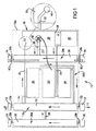
図1を参照すると、ここには脱塩パイプラインシステムの一部が示されている。脱塩パイプラインシステム10は、塩水源14と目標出口12との間を延び、塩水を搬送するための第1パイプライン12を有している。脱塩パイプラインシステム10は、塩水脱塩装置18を有している。塩水脱塩装置18は、連結パイプ20、22を介して第1パイプライン12に流体連結されている。連結パイプ20により、塩水を第1パイプライン12から脱塩装置18に引くことを可能にする。連結パイプ22により、脱塩装置18内で脱塩されなかった塩水を第1パイプライン12に戻すことを可能にする。
Referring to FIG. 1, here is a portion of a desalting pipeline system. The
塩水脱塩装置18は、第1パイプライン12から引いた塩水の一部を脱塩するように構成されている。実際、脱塩装置18は、塩水の一部を淡水に変換することを意図したものである。脱塩装置18は、塩水源14と目標出口16との間を延びる第2パイプライン24に連結パイプ27を介して流体連結され、これにより、脱塩装置18内で生成された脱塩(蒸発)水が第2パイプライン24に搬送される。第2パイプライン24は、脱塩された淡水のみを搬送する。
The salt
脱塩パイプラインシステム10は、塩水源14と目標出口16との間を延びる第3パイプライン26を有し、第3パイプライン26は、第1パイプライン12に連結パイプ28を介して流体連結されている。第3パイプライン26は、オプション(任意)であり、この実施形態では、脱塩装置18が第1パイプライン12から取出した塩水を脱塩するときに塩水を第1パイプライン12に補充するためのものである。
The
一般に、目標出口16には、ダム、リザーバ、集水域又は他の淡水リザーバが含まれ、塩水源14は海であると理解されよう。また、塩水源14には、例えば塩害を受けた川又は水路が含まれると考えられよう。この点で、本発明は、このような川又は水路の塩レベルを望むように低減させるのに使用できる。 In general, the target outlets 16 will include dams, reservoirs, catchments or other fresh water reservoirs, and it will be understood that the salt water source 14 is the sea. Also, the salt water source 14 may be considered to include, for example, a river or waterway that has suffered salt damage. In this regard, the present invention can be used to reduce such river or waterway salt levels as desired.
図示されてはいないが、脱塩パイプラインシステム10は、2つの脱塩モジュールを有するのがよい(図9には、2つの脱塩モジュールを備えたシステムが示されている)。任意の数の脱塩モジュールを、パイプラインシステム10に沿う所望の箇所及び/又は便利な箇所に配置できる。各モジュールは、脱塩装置18と、第1パイプライン12のセクション12aと、第2パイプライン24のセクション24aと、第3パイプライン26のセクション26a(オプション)とを有している。オプションとしての第3パイプラインが使用されない場合には、複数の第1パイプラインのセクションが互いに流体連結されるのがよく、さもなければ、塩又は汚水の源に別々に流体連結されなくてはならない。例えば、脱塩装置18は、パイプラインシステム10に沿って配置され、これらの各箇所において水を脱塩する。
Although not shown, the
各脱塩モジュール18aを塩水源14と目標出口16との間で直列に連結することを考えることができる。しかしながら、脱塩モジュールであるため、脱塩パイプラインシステム10は、2つ又は3つ以上の脱塩モジュール18aを並列に組込んでもよい。所望ならば、各脱塩モジュール18aに2つ以上の脱塩装置18を設けてもよい。脱塩モジュール18a及びパイプラインシステムのセクション(部分)は、任意所望の順序で構成できる。一般的に言って、各脱塩モジュール18aは地上に配置されるが、脱塩パイプラインシステムのセクションは、地上又は地下のいずれにも配置できる。
It can be envisaged to connect each desalting module 18 a in series between the salt water source 14 and the target outlet 16. However, since it is a desalting module, the
各脱塩モジュールは、パイプラインセクション12a、24a、26aをそれぞれ、それに隣接した脱塩モジュールのパイプラインセクション又はパイプラインセクションのパイプラインセクションに連結するコネクタ12b、24b、26bを有している。
Each desalting module has a
脱塩パイプラインシステム10に使用される脱塩装置18は、図4、図5及び図6により詳細に示されている。脱塩装置18は、脱塩チャンバ30を有している(図1の拡大挿入図も参照されたい)。脱塩チャンバ30は、塩水を第1パイプライン12から連結パイプ20を介して受入れる塩水入口32と、スプレー又はシャワー形ヘッド46の形態をなす散水ユニットとを有している。作動に際し、脱塩チャンバ30は、それに入る塩水の塩分割合よりも大きい塩分割合を有する高温の塩水を収容している。塩は脱塩チャンバ30の底に集合し易く、周期的に除去される。脱塩チャンバ30はまた、蒸発水を脱塩チャンバ30内から連結パイプ26を介して第2パイプライン24に取出す蒸発水出口36と、蒸発していない塩水を脱塩チャンバ30から取出す塩水出口すなわちオーバーフロー38とを有している。オーバーフロー38は、チャンバ壁の任意適当な位置に設けられる。
The
脱塩装置18は集塩器40を有し、蒸発していない全ての塩水が、脱塩チャンバから第1パイプラインに戻る前に集塩器40に通される。集塩器40はまた、脱塩チャンバ30内で生成された塩を収集するために設けられる。しかしながら、他の実施形態(図3に示す実施形態)では、脱塩チャンバ18内で生成された塩は、第1パイプライン12内に戻されて収集され、できるならば、目標出口16又は脱塩パイプラインシステム10内の他の適当な箇所で処理される。集塩器40は、図3に参照番号218で示すように、脱塩チャンバ30内に設けられてもよいし、図示のように別体のチャンバとして形成されてもよい。
The
ソーラー式水ヒータ42が、第1パイプライン12と脱塩チャンバ30との間に流体連結され、塩水が脱塩チャンバ30に入る前、塩水を約55℃又はそれよりも高い適当な温度に加熱する。塩水を加熱することにより、脱塩チャンバ30内での蒸発レベルが増大される。これにより、脱塩チャンバ30内での脱塩プロセスの効率が高められる。
A
熱サイホンとして作用する第2ソーラー式ヒータ44が、集塩器40内から蒸発していない全ての塩水を除去する。蒸発していない塩水は、パイプ22を通って抜取られ且つパイプ500を介して第1パイプライン12に戻される。
The second
ソーラー式ヒータは必ずしも使用する必要はなく、或る産業用途では、他の熱源又はエネルギ源の方がより良い選択となることもある。任意の形式のヒータを使用できるが、他のヒータが熱サイホンとして作用しない場合には、ヒータ以外にポンプが必要になることもある。 Solar heaters do not necessarily have to be used, and in some industrial applications other heat or energy sources may be a better choice. Any type of heater can be used, but if the other heater does not act as a thermosyphon, a pump may be required in addition to the heater.
脱塩チャンバ30内において、この脱塩チャンバ30内に入る塩水を脱塩チャンバ30の頂部から下方に向かって噴霧し、シャワー吐出し又は分散させるためのシャワー装置又はスプレー装置46が設けられている。塩水は、塩水からの淡水の蒸発を補助するために分散される。塩水を必ずしも下方に噴霧する必要がないことが理解されよう。塩水を、例えば上向きに噴霧させてもよい。また、脱塩チャンバ内に入る塩水が、例えば蒸発パッド内で懸濁させるべきものである場合、実際には塩水を噴霧させる必要はなく、塩水を簡単に脱塩チャンバ内に注いでもよい。
In the
脱塩(蒸発)プロセスを更に補助するために、高温の塩水のシャワー又はスプレーを横切るように又はその中を通るように、空気を脱塩チャンバ内に供給する空気取入口48(図4及び図5参照)が設けられている。 To further assist the desalination (evaporation) process, an air intake 48 (FIGS. 4 and 4) that supplies air into the desalination chamber across or through a hot salt water shower or spray. 5).
脱塩チャンバ30は、蒸発水を蒸発水出口36から抜取るための抜取りファン50を有している。抜取りファン50は、任意適当な手段を動力源とし、図示の実施形態ではソーラーパネル52を動力源としている。抜取りファン50は、連結パイプ27内に配置されてもよい。
The
脱塩パイプラインシステム10は、1つ又は2つ以上のポンプ(図示せず)の形態をなし且つ塩水を第1パイプライン12及び第3パイプライン26の各々を通して目標出口に向かってポンプ送りするための手段を有している。同様に、脱塩パイプラインシステム10は、1つ又は2つ以上のポンプ(図示せず)の形態をなし且つ第2パイプライン24内の脱塩された水を目標出口に向かってポンプ送りするための手段を有している。これらのポンプは、ソーラー又は風力を動力源とするもので構成されてもよいし、他の任意適当なポンプで構成されてもよい。
図示していないが、第1パイプライン12、第2パイプライン24及び第3パイプライン26の各々は、それらの脱塩装置18に隣接し又はその近くの長さ部分の少なくとも一部に沿って断熱され、低温の外部の周囲温度へのエネルギ損失を低減させる。任意適当な断熱形式を採用できる。
Although not shown, each of the
第2パイプライン26は、シェル/チューブ熱交換器501(図6)の一部を形成しており、淡水蒸気が内側チューブを通って流れ且つ凝縮され、塩水が内側チューブを包囲するシェルの中を流れる。このような構成において、塩水は、水蒸気が凝縮するときに水蒸気から失われたエネルギを吸収する。これにより、脱塩チャンバ30に入る塩水の温度が上昇し、脱塩プロセスの全体的効率が向上する。
The
作動に際し、加熱した塩水を第1パイプライン12から塩水入口32を通して脱塩チャンバ30内に供給する。シャワー装置又はスプレー装置46が、加熱された塩水を脱塩チャンバ30の中で下方に噴霧し、シャワー吐出し又は分散させ、それと同時に、空気取入口48は、加熱水のシャワー又はスプレーを横切るように又はその中を通るように空気を脱塩チャンバ30内に供給される。抜取りファン50が、蒸発された淡水を蒸発水出口36から抜取ることを補助する。これと同時に、蒸発していない塩水を脱塩チャンバから塩水オーバーフロー出口38を通して直接的に又は集塩器40を通して第1パイプライン12に取出す。
In operation, heated brine is supplied from the
抜取りファン50は、他の任意適当な装置に置換できる。例えば、圧力制御装置(図示せず)を設けて、抜取りパイプ内の圧力が脱塩チャンバ30内の圧力より低いレベルに維持されるように抜取りパイプ内の圧力を制御する。このような構成は、脱塩チャンバの外部から脱塩チャンバ内に空気を引いて、空気流を制御するのに使用することもできる。
The
脱塩装置の作動効率を更に高めるため、加熱ユニットをスプレー装置46に設けて、脱塩チャンバに入る塩水を更に加熱してもよい。加熱ユニットは、ソーラーを動力源としてもよいし、他の任意適当な動力源を用いてもよい。
In order to further increase the operating efficiency of the desalination apparatus, a heating unit may be provided in the
塩及びその他の重い不純物は、オーバーフロー出口38の下の脱塩チャンバ30の底に溜まる傾向を有し、周期的に除去される。
Salt and other heavy impurities tend to collect at the bottom of the
脱塩チャンバ30に入る塩水を必ずしも加熱する必要がないことが理解されよう。或る気候条件では、脱塩プロセスは、付加加熱を行うことなく実行される。これらの気候条件では、パイプラインの断熱も不要である。
It will be appreciated that the brine entering the
塩は、任意適当な箇所で、多数の脱塩システムから取出される。 Salt is removed from a number of desalting systems at any suitable location.
脱塩パイプラインシステム10に沿って隣接したモジュール18a間で空気圧力を移送するための空気圧力移送チューブ502が設けられている。変形例として、蒸発水が逃げることを防止するフィルタを有する圧力制御装置を使用して、第2パイプライン内の任意の過剰圧力を大気中に放出させてもよい。
An air
図2に示す脱塩パイプラインシステム110は、図1に示したシステム10と多くの点で同様である。両脱塩パイプラインシステム10、110の間の1つの顕著な相違点は、脱塩チャンバ130から第1パイプライン112に戻る塩水が、ソーラーを動力源とする熱サイホンによってポンプ送りされるのではなく、ソーラーを動力源とするポンプ144によってポンプ送りされることである。ポンプ144は、脱塩チャンバ130の抜取りファン150の動力源として使用されるソーラーパネル152と同じソーラーパネル152を動力源としている。
The
同様に、図3に示す脱塩パイプラインシステム210は、図1に示した脱塩パイプラインシステム10と多くの点で同様である。1つの顕著な相違点は、脱塩チャンバ230の抜取りファン250が、ソーラーパネルを動力源とするのではなく、風力ユニット252を動力源としていることである。他の相違点は、脱塩チャンバ及び集塩器が1つのチャンバ214内に組合わされていることである。これにより、塩及びその他の重い不純物は、出口222aの下の脱塩チャンバ230の底に溜まるのではなく、第1パイプライン212の中を通って目標出口に向かって連続する。
Similarly, the
また、この構成には、第1パイプライン212と第3パイプライン226との間に連結パイプが設けられていない。その代わりに、第1パイプライン212を補充する塩水は、最初、第2パイプライン224の外側シェルを通り、連結パイプ252を介して導かれる。第2パイプライン224は、シェル/チューブ熱交換器又はその他の任意適当な熱交換器として構成されている。この塩水は、次に、第2パイプライン224の外側シェルから、連結パイプ254を介して第1パイプライン212に戻される。脱塩チャンバ230を出た後、ソーラー式水ヒータ244内で加熱された塩水は、第1パイプライン212に戻されて次の脱塩装置に導かれるか、脱塩チャンバ230に戻される。
In this configuration, no connection pipe is provided between the
図7を参照すると、ここには、脱塩パイプラインシステム310の単一ユニット部分が示されている。この実施形態では、脱塩パイプラインシステム310は、水再循環システムとして構成されている。第1パイプライン312は、汚水源314と目標出口316との間を延びる、第3パイプライン326(汚水源である)及び第2パイプライン(淡水を収容している)に流体連結されており、これらのパイプラインを通して汚水を搬送する。
Referring to FIG. 7, a single unit portion of a
この脱塩パイプラインシステムは、塩水脱塩装置(この場合には汚水クリーナ)318を有している。脱塩装置318は、連結パイプ320、322を介して第1パイプライン312に流体連結されている。連結パイプ320は、汚水を第1パイプライン312から脱塩装置318内に引くことができる。連結パイプ322は、脱塩装置318内で浄化されなかった汚水を第1パイプライン312に戻すことができる。
The desalting pipeline system includes a salt water desalination device (in this case, a sewage cleaner) 318. The
脱塩装置318は、第1パイプライン312から引かれた汚水の一部を浄化するためのものである。実際に、脱塩装置318は、汚水の一部を淡水に変換することを意図している。脱塩装置318は、汚水源314と目標出口316との間を延びる第2パイプライン324に、連結パイプ327を介して流体連結され、脱塩装置318内で生成された脱塩水が第2パイプライン324に搬送される。第2パイプライン324は、脱塩された淡水のみを搬送する。
The
脱塩パイプラインシステム310は、汚水源314と目標出口316との間を延びる第3パイプライン326を有し、第3パイプライン326は、連結パイプ328を介して第1パイプライン312に流体連結されている。
The
図8には、脱塩装置318の拡大図が示されている。この実施形態の脱塩装置318は、脱塩チャンバ330を有している。脱塩チャンバ330は、第1パイプライン312から流体連結パイプ320を介して汚水を受入れる多数の塩水入口332を有している。この実施形態では、汚水は、塩水入口332から蒸発パッド(図示せず)上に向かって下方に噴霧される。作動に際し、脱塩チャンバ330は、それに入る汚水の濃度より高い汚れ濃度をもつ高温の汚水を収容している。蒸発パッドの中に勢いよく流され且つ蒸発していない水の中の汚物は、脱塩チャンバ330の底に集められる。蒸発していない汚水は流体連結部331を介して取出される。汚水(懸濁固形物を含まない汚水)は、処理のために連結パイプ322を介して第1パイプライン312に戻され、連結パイプ322は、懸濁固形物が戻されることを防止するための任意適当な手段(例えばフィルタ)を使用する。汚水は、出口362から取出すために抜取られる。脱塩チャンバ330はまた、凝縮チャンバ364を有している。この実施形態では、凝縮チャンバ364は、蒸発チャンバ330に空気流連通している。この実施形態では、凝縮チャンバ364は、ソーラー式冷却器366によって冷却される。熱は、凝縮チャンバ364から蒸発チャンバ330に移送される。
FIG. 8 shows an enlarged view of the
凝縮チャンバ364内の温度の低下により、淡水の産出量を増大させる。凝縮プロセス中に失われた熱は、蒸発チャンバ330内の空気の加熱に有効に使用できる。全蒸発量を増大させるために、多数の蒸発パッドの間において加熱を追加することを有利に使用できる(塩水入口332と脱塩チャンバ330とが隣接していることに留意されたい)。
Decreasing the temperature in the
任意適当なヒートポンプ装置を使用できるが、ソーラーを動力源とするヒートポンプ及び/又は高効率ヒートポンプを使用するのが有利である。エネルギを凝縮プロセスから回収してそのエネルギを蒸発プロセスに入力させることは、蒸発プロセスの正味エネルギコストの低減に有利である。 Any suitable heat pump device can be used, but it is advantageous to use a solar powered heat pump and / or a high efficiency heat pump. Recovering energy from the condensation process and inputting that energy into the evaporation process is advantageous in reducing the net energy cost of the evaporation process.
この実施形態では、ソーラー式冷却器は、汚水が蒸発チャンバ330に流入する前、汚水からのいくらかの熱を使用する。このことは、ソーラー式冷却器368の効率、凝縮チャンバ364からの熱の回収、及びこの回収熱の蒸発チャンバ330内への入力によって有利になる。
In this embodiment, the solar cooler uses some heat from the sewage before it enters the
空気は、流れ制御ファン370を用いて、脱塩チャンバ330を通して循環される。
Air is circulated through the
この実施形態では、汚水が連結パイプ320を介して抜取られる前、且つ、蒸発チャンバ330内に流入する前、第1パイプライン312のフラットプレート372とソーラー式チューブヒータ374との組合せを使用して、汚水を予熱するのが有利である。また、オプションとしての付加ガス加熱ユニット376も示されている。この実施形態では、空気が蒸発チャンバ330に流入する前、フラットプレート372とソーラー式チューブヒータ374との組合せを用いて、空気を予熱するのが有利である。
In this embodiment, a combination of the
空気及び/又は水を予熱する多くの方法により、脱塩プロセスの効率を高めることができる。比較的低い温度が一層有利であるので、本発明は多くの低グレード熱源を利用できる。 Many methods of preheating air and / or water can increase the efficiency of the desalination process. Since a relatively low temperature is more advantageous, the present invention can utilize many low grade heat sources.
この実施形態では、プロセスの効率を高めるか、他の幾つかの望ましい効果を得るかの何れかのために、幾つかのガスを脱塩チャンバ330に有利に添加する可能性を有する選択的なガス混合が示されている。
In this embodiment, selective gas with the possibility of advantageously adding some gas to the
図9は多ユニットの例410を示し、第3パイプライン426は、多脱塩ユニット418に流体連結されていることが理解されよう。
FIG. 9 shows an example 410 of multiple units, and it will be appreciated that the
本発明は、潜在的な多くの利益を与える。 The present invention offers many potential benefits.
システムをモジュール式に作ることができるので、特定用途に適したシステムを比較的容易に設計することが可能になる。 Since the system can be made modular, a system suitable for a specific application can be designed relatively easily.
モジュール式であるので、脱塩装置の故障時、補修時、メンテナンス時又はテロリストによる破壊時、脱塩装置を比較的簡単にバイパスさせることができる。また、1つの脱塩装置が作動不能になった場合でも、3つのパイプラインのうちのいずれかの壊れたセクションをひとたび補修し又は置換すれば、システムの残余の脱塩装置を引き続いて作動させることができる。 Since it is modular, the desalinator can be bypassed relatively easily when the desalinator fails, is repaired, maintained, or destroyed by a terrorist. Also, even if one desalinator becomes inoperable, once the broken section of any of the three pipelines is repaired or replaced, the rest of the system desalinator will continue to operate. be able to.
有利なことは、システムが、脱塩装置をパイプラインシステムに沿う任意の箇所に実際に配置できることである。 The advantage is that the system can actually place the desalination unit anywhere along the pipeline system.
システムに沿う任意の箇所で脱塩装置によって生成される淡水は、出口に向かう淡水パイプ内又は任意の淡水抜取り箇所で連続して流れる。 Fresh water produced by the desalinator at any point along the system flows continuously in the fresh water pipe toward the outlet or at any fresh water withdrawal point.
有利なことは、本発明は、パイプラインシステムに沿う脱塩装置内で多量の脱塩が行われるため、パイプラインシステムの最終目的地では非常に小さい脱塩プラントで済むことである。実際に、本発明のシステムでは、目標出口における脱塩装置の必要性は選択的である。 Advantageously, the present invention requires a very small desalination plant at the final destination of the pipeline system, since a large amount of desalination takes place in the desalination unit along the pipeline system. Indeed, in the system of the present invention, the need for a desalinator at the target outlet is optional.
本発明の脱塩プロセスは、全体的に駆動されるものでない場合、既存の脱塩及びパイプラインシステムとは異なり、ソーラー動力及び風力等の環境的に優しい動力源によって大部分駆動される。 The desalination process of the present invention, if not totally driven, is largely driven by environmentally friendly power sources such as solar power and wind power, unlike existing desalination and pipeline systems.
本発明のシステムは、数百キロメートルにわたる場合であっても、数千キロメートルにわたる場合であっても、1キロメートルより短い場合であっても等しく適合可能である。 The system of the present invention is equally adaptable over hundreds of kilometers, thousands of kilometers, or shorter than one kilometer.
本発明のシステムは、家庭用及び/又は商業用及び/又は工業用並びに農業用に使用できる。 The system of the present invention can be used for household and / or commercial and / or industrial and agricultural purposes.
本発明のシステムは、種々の水及び他の流体から、広範囲の他のあらゆる蒸発していない組成物/汚染物を除去するのに使用できる。かくして、本明細書での「脱塩」についての言及は、「脱塩及び/又は汚染除去」についての言及を含むことを理解すべきである。本発明のシステムは、沈殿物が蒸発せず且つ流体が使用作動温度で蒸発する限り、沈殿物を流体から除去するのに非常に有効に使用できる。一例として、本発明のシステムは、井戸水から汚れを除去するのに使用できる。変形例として、本発明のシステムは、池からの汚れた及び/又は汚染された及び/又は寄生虫を含む水を浄化するのに使用できる。 The system of the present invention can be used to remove a wide range of any other non-evaporated composition / contaminant from various waters and other fluids. Thus, it should be understood that references herein to “desalting” include references to “desalting and / or decontamination”. The system of the present invention can be used very effectively to remove the precipitate from the fluid as long as the precipitate does not evaporate and the fluid evaporates at the service operating temperature. As an example, the system of the present invention can be used to remove dirt from well water. Alternatively, the system of the present invention can be used to purify dirty and / or contaminated water from ponds and / or containing parasites.
本発明のシステムの可能性ある更に別の使用例として、製紙プロセスで生じる不純物を水から除去して、未処理の水に比べてより容易かつ環境的に好ましく廃棄できる淡水及びスラッジを作ることが含まれる。 Yet another possible use of the system of the present invention is to remove impurities generated in the papermaking process from water to produce fresh water and sludge that can be disposed of more easily and environmentally favorably than untreated water. included.
また、本発明のシステムは、容易に入手できる海水を使用可能にする。 The system of the present invention also makes it possible to use readily available seawater.
本発明のシステムが、塩水用及び脱塩水用の別々のパイプラインを備えていれば有利である。従って、塩水脱塩水を汚染することは、不可能ではないが困難である。 It is advantageous if the system according to the invention comprises separate pipelines for salt water and demineralized water. Therefore, it is difficult, if not impossible, to contaminate brine demineralized water.
本発明のシステムは、川及び水路における好ましくないほど高い塩レベルを低下させるのに、幾らかの塩水を本発明の脱塩パイプラインシステムに取入れ、次に淡水を川又は水路に戻すことによって有利に使用できる。 The system of the present invention is advantageous by taking some salt water into the desalting pipeline system of the present invention and then returning fresh water back to the river or water channel to reduce undesirably high salt levels in rivers and waterways. Can be used for
塩水を目的地で処理することは、有効であるとはいえ必要なことではない。目標出口において、塩水パイプライン(第1パイプライン及び第3パイプライン)に蓋をしてもよい。 Treatment of salt water at the destination is effective but not necessary. At the target outlet, the salt water pipeline (the first pipeline and the third pipeline) may be capped.
また、高濃度の塩水を作ることが有利であることを理解されたい。従って、本発明は、塩水を高濃度塩水及び淡水(又は低濃度塩水)の別々の産出に変換するのに使用でき、高濃度塩水及び淡水が両方とも有用であることを理解すべきである。 It should also be understood that it is advantageous to produce a high concentration of brine. Thus, it should be understood that the present invention can be used to convert salt water into separate productions of high and low concentration brine (or low concentration brine), both high concentration brine and fresh water being useful.
同様に、本発明のシステムを汚染流体の処理に使用するならば、汚染流体を高汚染流体及び非汚染流体の別々の産出に変換するのに有利に使用でき、高汚染流体及び低汚染流体が両方とも有用である。 Similarly, if the system of the present invention is used to treat contaminated fluids, it can be advantageously used to convert contaminated fluids into separate productions of highly contaminated and non-contaminated fluids, Both are useful.
最後に、本発明の精神及び範囲から逸脱することなく、上記部品の構造及び配置に種々の変更及び/又は付加を導入できることを理解すべきである。 Finally, it should be understood that various changes and / or additions can be made to the structure and arrangement of the components without departing from the spirit and scope of the invention.
本願からの優先権を主張する全てのオーストラリア国特許出願及び外国出願において求められている特許請求の範囲を制限することなく、別掲の範囲を特許請求する。 The following claims are claimed without limiting the claims required in all Australian patent applications and foreign applications claiming priority from this application:
Claims (40)
前記第1パイプラインに流体連結された少なくとも1つの塩水脱塩装置と、を有し、前記少なくとも1つの塩水脱塩装置は、塩水を前記第1パイプラインから前記少なくとも1つの脱塩装置に引くことを可能にし、
各塩水脱塩装置は、前記第1パイプラインから引いた塩水の少なくとも一部を脱塩するように構成され、
各塩水脱塩装置は、前記塩水源と目標出口との間を延びる第2パイプラインに流体連結され、脱塩装置で脱塩された水が前記第2パイプラインに搬送される、パイプラインシステム。 A first pipeline extending from a salt water source for conveying salt water;
At least one salt water desalination device fluidly connected to the first pipeline, the at least one salt water desalination device drawing salt water from the first pipeline to the at least one desalination device. Make it possible,
Each salt water desalination device is configured to desalinate at least part of the salt water drawn from the first pipeline,
Each salt water desalination apparatus is fluidly connected to a second pipeline extending between the salt water source and a target outlet, and water desalted by the desalination apparatus is conveyed to the second pipeline. .
塩水入口と、
前記塩水チャンバ内に水を分散させる散水ユニットと、
蒸発水を前記塩水チャンバ内から取出すための蒸発水出口と、
蒸発していない塩水を前記塩水チャンバ内から取出すための塩水出口と、
空気流を前記塩水チャンバ内に供給する手段とを有する、脱塩装置。 A desalination apparatus for a desalination pipeline system, wherein the desalination apparatus has a desalination chamber,
A salt water inlet,
A watering unit for dispersing water in the salt water chamber;
An evaporating water outlet for removing evaporating water from the salt water chamber;
A salt water outlet for removing non-evaporated salt water from within the salt water chamber;
Means for supplying an air flow into the brine chamber.
水が通り且つその水を分散させる1つ又は2つ以上のシャワー、スプレー又は他の散水装置を有する、散水手段。 Watering means for dispersing water flowing into the desalination chamber,
Watering means comprising one or more showers, sprays or other watering devices through which water passes and disperses the water.
塩水を、塩水入口から脱塩チャンバ内に供給する段階と、
塩水を前記脱塩チャンバ内で分散させる段階と、
空気流を前記脱塩チャンバ内に供給する段階と、
蒸発水を前記脱塩チャンバから蒸発水出口を通して取出す段階と、
蒸発していない塩水を前記脱塩チャンバ内から塩水出口を通して取出す段階と、を有する方法。 A method for desalinating salt water,
Supplying salt water from a salt water inlet into the desalination chamber;
Dispersing salt water in the desalting chamber;
Supplying an air flow into the desalting chamber;
Removing evaporated water from the desalting chamber through an evaporated water outlet;
Removing unvaporized salt water from within the desalting chamber through a salt water outlet.
前記第1パイプラインに流体連結された少なくとも1つの汚染除去ユニットと、を有し、各汚染除去ユニットは、汚染除去流体を前記第1パイプラインから前記少なくとも1つの汚染除去ユニットに引くことを可能にし、
各汚染除去ユニットは、汚染除去流体源と目標出口との間を延びる第2パイプラインに流体連結され、前記汚染除去ユニット内で汚染除去された流体が前記第2パイプラインに搬送される、汚染除去パイプラインシステム。 A first pipeline extending from a decontamination fluid source to convey the decontaminated fluid;
At least one decontamination unit fluidly coupled to the first pipeline, each decontamination unit capable of drawing decontamination fluid from the first pipeline to the at least one decontamination unit West,
Each decontamination unit is fluidly coupled to a second pipeline extending between a decontamination fluid source and a target outlet, and the decontaminated fluid in the decontamination unit is conveyed to the second pipeline. Removal pipeline system.
汚染除去流体の入口と、
前記汚染除去チャンバ内に汚染除去流体を分散させる分散ユニットと、
蒸発した流体を前記汚染除去チャンバ内から取出すための蒸発流体出口と、
蒸発していない汚染流体を前記汚染除去チャンバ内から取出すための汚染流体出口と、
空気流を前記汚染除去チャンバ内に供給する手段とを有する、汚染除去ユニット。 A decontamination unit for a decontamination pipeline system, the decontamination unit having a decontamination chamber, the decontamination chamber comprising:
A decontamination fluid inlet;
A dispersion unit for dispersing a decontamination fluid in the decontamination chamber;
An evaporating fluid outlet for removing evaporated fluid from within the decontamination chamber;
A contaminated fluid outlet for removing non-evaporated contaminated fluid from within the decontamination chamber;
Means for supplying an air flow into the decontamination chamber.
流体が通り且つその流体を分散させるシャワー、スプレー又は他の流体分散装置の1つを有する、流体分散手段。 Fluid dispersion means for dispersing fluid flowing into the decontamination chamber,
A fluid dispersion means comprising one of a shower, spray or other fluid dispersion device through which the fluid passes and disperses the fluid.
Applications Claiming Priority (3)
| Application Number | Priority Date | Filing Date | Title |
|---|---|---|---|
| AU2005906494A AU2005906494A0 (en) | 2005-11-22 | A desalination pipeline | |
| AU2006903448A AU2006903448A0 (en) | 2006-06-27 | A pipeline system | |
| PCT/AU2006/001748 WO2007059561A1 (en) | 2005-11-22 | 2006-11-20 | A pipeline system |
Publications (2)
| Publication Number | Publication Date |
|---|---|
| JP2009516788A true JP2009516788A (en) | 2009-04-23 |
| JP2009516788A5 JP2009516788A5 (en) | 2010-01-07 |
Family
ID=38066828
Family Applications (1)
| Application Number | Title | Priority Date | Filing Date |
|---|---|---|---|
| JP2008541542A Abandoned JP2009516788A (en) | 2005-11-22 | 2006-11-20 | Pipeline system |
Country Status (7)
| Country | Link |
|---|---|
| US (1) | US20100044206A1 (en) |
| EP (1) | EP1951624A4 (en) |
| JP (1) | JP2009516788A (en) |
| CA (1) | CA2630582C (en) |
| EG (1) | EG26261A (en) |
| RU (1) | RU2470869C2 (en) |
| WO (1) | WO2007059561A1 (en) |
Cited By (1)
| Publication number | Priority date | Publication date | Assignee | Title |
|---|---|---|---|---|
| JP2009172562A (en) * | 2008-01-28 | 2009-08-06 | Katsumi Iida | Evaporator |
Families Citing this family (7)
| Publication number | Priority date | Publication date | Assignee | Title |
|---|---|---|---|---|
| US8361281B2 (en) | 2008-08-13 | 2013-01-29 | Lytesyde, Llc | Desalinization apparatus and method |
| US8216455B1 (en) * | 2008-12-01 | 2012-07-10 | O'brien Mackenzie Anne | Water handling system |
| CN102695676A (en) * | 2009-10-23 | 2012-09-26 | 奥特拉公司 | Leverage of waste product to provide clean water |
| CN102180530B (en) * | 2011-03-25 | 2012-09-26 | 何敬东 | Device and method for sea water desalination by using solar energy and potential energy |
| US9468863B2 (en) | 2013-07-09 | 2016-10-18 | Herbert J. Roth, Jr. | System and method of desalinating seawater |
| US20230097411A1 (en) * | 2021-09-28 | 2023-03-30 | SaeHeum Song | Water-Mediated Thermal Conditioning System |
| CN116983682B (en) * | 2023-09-27 | 2023-11-28 | 云南能投绿色新材有限责任公司 | Caustic soda evaporation equipment |
Family Cites Families (30)
| Publication number | Priority date | Publication date | Assignee | Title |
|---|---|---|---|---|
| US3288685A (en) * | 1962-08-17 | 1966-11-29 | Joseph Kaye & Company | Multiple-phase ejector distillation apparatus and desalination process |
| US3425914A (en) * | 1966-10-26 | 1969-02-04 | Gen Motors Corp | Spray-type distillation using gas turbine exhaust distilland heating |
| US3674652A (en) * | 1969-08-14 | 1972-07-04 | Aluminum Co Of America | Method of water purification |
| US4172767A (en) * | 1976-07-26 | 1979-10-30 | Sear Walter E | Water purification system |
| SU1022947A2 (en) * | 1979-09-17 | 1983-06-15 | Одесский Инженерно-Строительный Институт | Water desalination method |
| SU929794A1 (en) * | 1980-10-22 | 1982-05-23 | Северо-Кавказский научно-исследовательский институт природных газов | Method of working thermal water fields |
| US4363703A (en) * | 1980-11-06 | 1982-12-14 | Institute Of Gas Technology | Thermal gradient humidification-dehumidification desalination system |
| SU966442A1 (en) * | 1981-03-06 | 1982-10-15 | За витель | Method of desalinating water in solar desalination plant |
| US4504362A (en) * | 1982-09-13 | 1985-03-12 | Kruse Clifford L | Solar desalination system and method |
| DE3337360A1 (en) * | 1983-10-14 | 1985-05-02 | Kalawrytinos, Georg, Dr., 5190 Stolberg | METHOD AND DEVICE FOR WASTE WATER TREATMENT |
| IL87088A (en) * | 1988-07-12 | 1993-05-13 | Ormat Turbines 1965 Ltd | Method of and apparatus for evaporating and cooling liquid |
| US5078880A (en) * | 1990-09-12 | 1992-01-07 | Water Technology Assessment Group | Vortex desalination system |
| US5645693A (en) * | 1991-06-28 | 1997-07-08 | Goede; Gabor | Plant for sea water desalinizing using solar energy |
| US5282979A (en) * | 1992-09-30 | 1994-02-01 | Wilson Henry A | Desalination system having rechargeable syphon conduit |
| US5744008A (en) * | 1996-01-02 | 1998-04-28 | Oceanit Laboratories, Inc. | Hurricane tower water desalination device |
| US5729987A (en) * | 1996-02-27 | 1998-03-24 | Miller; Joel V. | Desalinization method and apparatus |
| RU2099289C1 (en) * | 1996-03-25 | 1997-12-20 | Юрий Борисович Кашеваров | Sea water desalter |
| DE19621042A1 (en) * | 1996-05-24 | 1997-11-27 | Noell Lga Gastechnik Gmbh | Sea- or lake water desalinator constructed as floating unit, e.g. as a boat |
| US6494995B1 (en) * | 1997-12-12 | 2002-12-17 | Hammam Jamil Girgiess Battah | Solar distillation system |
| ATE232414T1 (en) * | 1999-05-27 | 2003-02-15 | Tno | METHOD FOR PURIFYING LIQUIDS BY MEMBRANE DISTILLATION, IN PARTICULAR FOR OBTAINING SALINATED WATER FROM SEAWATER OR BRACKET WATER OR PROCESS WATER |
| RU2165890C1 (en) * | 2000-01-12 | 2001-04-27 | Государственное унитарное предприятие Центральный аэрогидродинамический институт им. проф. Н.Е. Жуковского | Solar desalting unit |
| WO2004014802A1 (en) * | 2002-08-07 | 2004-02-19 | David Taran | Water-desalting plant |
| US7431806B2 (en) * | 2002-09-20 | 2008-10-07 | Lev Group, Llc | Low energy vacuum distillation method and apparatus |
| US7416666B2 (en) * | 2002-10-08 | 2008-08-26 | Water Standard Company | Mobile desalination plants and systems, and methods for producing desalinated water |
| US6919000B2 (en) * | 2002-12-17 | 2005-07-19 | University Of Florida | Diffusion driven desalination apparatus and process |
| AU2002361773A1 (en) * | 2002-12-17 | 2004-07-29 | University Of Florida | Diffusion driven desalination apparatus and process |
| US20050006491A1 (en) * | 2003-06-16 | 2005-01-13 | Jung-Ming Lin | Method of increasing the raining amounts in the desert and the apparatus thereof |
| US7501046B1 (en) * | 2003-12-03 | 2009-03-10 | The United States Of American, As Represented By The Secretary Of The Interior | Solar distillation loop evaporation sleeve |
| EP1746680A1 (en) * | 2005-07-20 | 2007-01-24 | Vlaamse Instelling Voor Technologisch Onderzoek (Vito) | Combination of a desalination plant and a salinity gradient power reverse electrodialysis plant and use thereof |
| US7897019B2 (en) * | 2006-06-26 | 2011-03-01 | Alan Dayton Akers | Tower for the distillation of seawater |
-
2006
- 2006-11-20 US US12/085,372 patent/US20100044206A1/en not_active Abandoned
- 2006-11-20 JP JP2008541542A patent/JP2009516788A/en not_active Abandoned
- 2006-11-20 EP EP06804551A patent/EP1951624A4/en not_active Withdrawn
- 2006-11-20 CA CA 2630582 patent/CA2630582C/en not_active Expired - Fee Related
- 2006-11-20 RU RU2008125141/05A patent/RU2470869C2/en not_active IP Right Cessation
- 2006-11-20 WO PCT/AU2006/001748 patent/WO2007059561A1/en active Application Filing
-
2008
- 2008-05-22 EG EG2008050854A patent/EG26261A/en active
Cited By (1)
| Publication number | Priority date | Publication date | Assignee | Title |
|---|---|---|---|---|
| JP2009172562A (en) * | 2008-01-28 | 2009-08-06 | Katsumi Iida | Evaporator |
Also Published As
| Publication number | Publication date |
|---|---|
| RU2008125141A (en) | 2009-12-27 |
| EP1951624A1 (en) | 2008-08-06 |
| RU2470869C2 (en) | 2012-12-27 |
| EG26261A (en) | 2013-06-04 |
| EP1951624A4 (en) | 2012-01-18 |
| CA2630582A1 (en) | 2007-05-31 |
| CA2630582C (en) | 2014-08-05 |
| WO2007059561A1 (en) | 2007-05-31 |
| US20100044206A1 (en) | 2010-02-25 |
Similar Documents
| Publication | Publication Date | Title |
|---|---|---|
| Fath | Solar distillation: a promising alternative for water provision with free energy, simple technology and a clean environment | |
| JP2009516788A (en) | Pipeline system | |
| US20160368785A1 (en) | Methods and systems to reduce air pollution combined with water desalination of power station's marine waste water | |
| EP2804682B1 (en) | Desalination station using a heat pump and photovoltaic energy | |
| US10144655B2 (en) | Systems and methods for distillation of water from seawater, brackish water, waste waters, and effluent waters | |
| CN102630216B (en) | Thermal distillation system and technique | |
| JP2011167628A (en) | Hollow fiber membrane module, membrane distillation type fresh water generator, and membrane distillation type desalination apparatus | |
| CN106830149A (en) | A kind of high salt water treatment facilities of utilization ultrasonic atomizatio combination solar energy evaporation | |
| WO2018045708A1 (en) | Indirect air-cooling unit heat recovery and water treatment device and method | |
| US7815776B2 (en) | Desalinization by evaporation from capillary material | |
| KR20110049551A (en) | Multi effect distiller using solar thermal energy | |
| WO2015083774A1 (en) | System for using recirculated water | |
| JP4250775B1 (en) | Seawater desalination equipment using air circulation | |
| US10414670B2 (en) | Systems and methods for distillation of water from seawater, brackish water, waste waters, and effluent waters | |
| Pandey et al. | Desalination and solar still: boon to earth | |
| CN103058302A (en) | Integrated solar seawater self-circulation desalting device and self-circulation desalting method | |
| EP2229988B1 (en) | A device and a method for liquid purification and power generation | |
| AU2006317500B2 (en) | A pipeline system | |
| JP3450939B2 (en) | Seawater desalination apparatus and seawater desalination method | |
| CN101351410A (en) | A pipeline system | |
| Younos et al. | Desalination: opportunities and challenges | |
| CN104108760A (en) | Device and method for treating oil-containing sewage | |
| RU2280011C1 (en) | Installation for desalination of the salt water and the method of desalination of the salt water with usage of the installation | |
| DE202006018685U1 (en) | Water distillation device comprises water evaporator, water condenser arranged in ground water medium, and water vapor conveying device to convey the produced vapor from the evaporator to the condenser | |
| WO2021053251A1 (en) | Evaporative purification system for the treatment of a liquid or gas effluent |
Legal Events
| Date | Code | Title | Description |
|---|---|---|---|
| A521 | Written amendment |
Free format text: JAPANESE INTERMEDIATE CODE: A523 Effective date: 20091105 |
|
| A621 | Written request for application examination |
Free format text: JAPANESE INTERMEDIATE CODE: A621 Effective date: 20091105 |
|
| A762 | Written abandonment of application |
Free format text: JAPANESE INTERMEDIATE CODE: A762 Effective date: 20101117 |