JP2009515481A - Apparatus and method for selecting frequency for transmission power control in wireless network - Google Patents
Apparatus and method for selecting frequency for transmission power control in wireless network Download PDFInfo
- Publication number
- JP2009515481A JP2009515481A JP2008540078A JP2008540078A JP2009515481A JP 2009515481 A JP2009515481 A JP 2009515481A JP 2008540078 A JP2008540078 A JP 2008540078A JP 2008540078 A JP2008540078 A JP 2008540078A JP 2009515481 A JP2009515481 A JP 2009515481A
- Authority
- JP
- Japan
- Prior art keywords
- signal
- channel
- atsc
- wran
- adjacent channel
- Prior art date
- Legal status (The legal status is an assumption and is not a legal conclusion. Google has not performed a legal analysis and makes no representation as to the accuracy of the status listed.)
- Withdrawn
Links
Images


Classifications
-
- H—ELECTRICITY
- H04—ELECTRIC COMMUNICATION TECHNIQUE
- H04J—MULTIPLEX COMMUNICATION
- H04J1/00—Frequency-division multiplex systems
-
- H—ELECTRICITY
- H04—ELECTRIC COMMUNICATION TECHNIQUE
- H04W—WIRELESS COMMUNICATION NETWORKS
- H04W16/00—Network planning, e.g. coverage or traffic planning tools; Network deployment, e.g. resource partitioning or cells structures
- H04W16/02—Resource partitioning among network components, e.g. reuse partitioning
- H04W16/10—Dynamic resource partitioning
-
- H—ELECTRICITY
- H04—ELECTRIC COMMUNICATION TECHNIQUE
- H04J—MULTIPLEX COMMUNICATION
- H04J11/00—Orthogonal multiplex systems, e.g. using WALSH codes
-
- H—ELECTRICITY
- H04—ELECTRIC COMMUNICATION TECHNIQUE
- H04L—TRANSMISSION OF DIGITAL INFORMATION, e.g. TELEGRAPHIC COMMUNICATION
- H04L27/00—Modulated-carrier systems
- H04L27/26—Systems using multi-frequency codes
- H04L27/2601—Multicarrier modulation systems
- H04L27/2626—Arrangements specific to the transmitter only
- H04L27/2627—Modulators
-
- H—ELECTRICITY
- H04—ELECTRIC COMMUNICATION TECHNIQUE
- H04L—TRANSMISSION OF DIGITAL INFORMATION, e.g. TELEGRAPHIC COMMUNICATION
- H04L5/00—Arrangements affording multiple use of the transmission path
- H04L5/003—Arrangements for allocating sub-channels of the transmission path
- H04L5/0044—Arrangements for allocating sub-channels of the transmission path allocation of payload
-
- H—ELECTRICITY
- H04—ELECTRIC COMMUNICATION TECHNIQUE
- H04L—TRANSMISSION OF DIGITAL INFORMATION, e.g. TELEGRAPHIC COMMUNICATION
- H04L5/00—Arrangements affording multiple use of the transmission path
- H04L5/003—Arrangements for allocating sub-channels of the transmission path
- H04L5/0058—Allocation criteria
- H04L5/0062—Avoidance of ingress interference, e.g. ham radio channels
-
- H—ELECTRICITY
- H04—ELECTRIC COMMUNICATION TECHNIQUE
- H04L—TRANSMISSION OF DIGITAL INFORMATION, e.g. TELEGRAPHIC COMMUNICATION
- H04L5/00—Arrangements affording multiple use of the transmission path
- H04L5/0091—Signaling for the administration of the divided path
- H04L5/0094—Indication of how sub-channels of the path are allocated
-
- H—ELECTRICITY
- H04—ELECTRIC COMMUNICATION TECHNIQUE
- H04W—WIRELESS COMMUNICATION NETWORKS
- H04W52/00—Power management, e.g. TPC [Transmission Power Control], power saving or power classes
- H04W52/04—TPC
-
- H—ELECTRICITY
- H04—ELECTRIC COMMUNICATION TECHNIQUE
- H04W—WIRELESS COMMUNICATION NETWORKS
- H04W72/00—Local resource management
- H04W72/04—Wireless resource allocation
- H04W72/044—Wireless resource allocation based on the type of the allocated resource
- H04W72/0453—Resources in frequency domain, e.g. a carrier in FDMA
-
- H—ELECTRICITY
- H04—ELECTRIC COMMUNICATION TECHNIQUE
- H04L—TRANSMISSION OF DIGITAL INFORMATION, e.g. TELEGRAPHIC COMMUNICATION
- H04L5/00—Arrangements affording multiple use of the transmission path
- H04L5/003—Arrangements for allocating sub-channels of the transmission path
- H04L5/0037—Inter-user or inter-terminal allocation
Abstract
無線エンドポイントは、基地局(BS)または顧客宅内機器(CPE)などの地域無線ネットワーク(WRAN)エンドポイントである。WRANエンドポイントは、使用のためにどのチャンネルが利用可能かどうか判定するためのチャンネルセンシングを行い、利用可能なチャンネル上で送信を開始する。隣接するチャンネル上でのTV放送の検出時に、WRANエンドポイントはその送信される信号の電力レベルを調整する。 A wireless endpoint is a regional wireless network (WRAN) endpoint, such as a base station (BS) or customer premises equipment (CPE). The WRAN endpoint performs channel sensing to determine which channels are available for use and initiates transmission on the available channels. Upon detecting a TV broadcast on an adjacent channel, the WRAN endpoint adjusts the power level of its transmitted signal.
Description
本発明は、一般に、通信システムに関し、より詳細には、無線システム、例えば、地上放送、セルラ、ワイヤレスフィデリティ(Wi−Fi)、衛星などに関する。 The present invention relates generally to communication systems, and more particularly to wireless systems such as terrestrial broadcast, cellular, wireless fidelity (Wi-Fi), satellites, and the like.
地域無線ネットワーク(WRAN)システムは、IEEE802.22標準規格グループで研究されている。WRANシステムは、主に都市および郊外地域にサービスを提供するブロードバンドアクセスと同様の性能で、地方の遠隔地域および低人口密度のサービス提供が不十分な地域に対処するため、干渉を避け、テレビジョン(TV)用周波数帯の使用されていないTV放送チャンネルを利用することを意図するものである。さらに、WRANシステムはまた、人口密度はより高いが、この周波数帯が利用可能な地域にサービスを提供するように拡張することができる可能性がある。 Regional wireless network (WRAN) systems are being studied by the IEEE 802.22 standard group. The WRAN system is similar in performance to broadband access, primarily serving urban and suburban areas, and avoids interference, avoiding interference and addressing remote areas in remote areas and areas with low population density. It is intended to use a TV broadcast channel that does not use the (TV) frequency band. In addition, the WRAN system may also be extended to serve areas where this frequency band is available, although the population density is higher.
上記のように、WRANは、TV放送などの既存の主な信号帯に干渉しないことが必要である。したがって、WRANエンドポイントは、既存のTV信号が存在しないチャンネルを使用する。しかし、チャンネルにTV信号がなくても、TV信号は隣接するチャンネルに存在する可能性がある。したがって、WRANエンドポイントからの送信信号は、さらに、非線形効果(例えば混変調積)により隣接するTV信号に干渉する可能性がある。ここでは、無線エンドポイントは、隣接するチャンネル上のTV放送に干渉するのを回避するために送信電力制御(TPC)を行う。特に、本発明の原理にしたがって、無線エンドポイントは、チャンネル上で信号を送信するが、隣接するチャンネル上で信号を検出すると、送信される信号の電力レベルを調整する。 As described above, WRAN needs not to interfere with existing main signal bands such as TV broadcasting. Therefore, the WRAN endpoint uses a channel for which no existing TV signal exists. However, even if there is no TV signal in the channel, the TV signal may exist in an adjacent channel. Thus, the transmitted signal from the WRAN endpoint may further interfere with adjacent TV signals due to non-linear effects (eg, cross modulation products). Here, the wireless endpoint performs transmission power control (TPC) to avoid interfering with TV broadcasts on adjacent channels. In particular, in accordance with the principles of the present invention, a wireless endpoint transmits a signal on a channel, but when it detects a signal on an adjacent channel, it adjusts the power level of the transmitted signal.
本発明の例示的な実施形態において、無線エンドポイントとは、基地局(BS)または顧客宅内機器(CPE)などの地域無線ネットワーク(WRAN)エンドポイントのことである。WRANエンドポイントは、どのチャンネルが使用のために利用可能か判定するためにチャンネルセンシングを行い、利用可能なチャンネルで送信を開始する。隣接するチャンネルでTV放送を検出すると、WRANエンドポイントはその送信される信号の電力レベルを調整する。 In an exemplary embodiment of the invention, a wireless endpoint is a regional wireless network (WRAN) endpoint, such as a base station (BS) or customer premises equipment (CPE). The WRAN endpoint performs channel sensing to determine which channels are available for use and starts transmitting on the available channels. When a TV broadcast is detected on an adjacent channel, the WRAN endpoint adjusts the power level of the transmitted signal.
上記を考慮して、かつ詳細な説明を読むことから明らかになるように、他の実施形態および特徴も可能であり本発明の原理の範囲に入る。 In view of the above, and as will become apparent from reading the detailed description, other embodiments and features are possible and are within the scope of the principles of the invention.
本発明の概念以外に、図に示されている要素はよく既知のので詳細には説明しない。さらに、TV放送、受信機、ネットワーキングおよびビデオエンコーディングについてはよく既知のと考えられるので、ここでは詳細には説明しない。例えば、本発明の概念以外に、ATSC(アドバンストテレビジョンシステム委員会)(ATSC)などのTV規格ならびにIEEE802.16、IEEE802.11hなどのネットワーキングのための現在のおよび提案されている推奨事項に関してはよく既知のと考え説明しない。ATSC放送信号についてのさらなる情報は、以下のATSC規格に記載されている。デジタルテレビジョン規格(A/53)、修正1および正誤表1を含む改定C、Doc.A/53C、ならびに非特許文献1。同様に、本発明の概念以外に、8レベル残留側波帯(8‐VSB)、直交振幅変調(QAM)、直交周波数分割多重(OFDM)または直交周波数分割多重接続(OFDMA)などの送信概念、および無線周波数(RF)フロントエンドなどの受信機構成要素、あるいは低雑音ブロック、チューナ、および変調器などの受信機セクション、相関器、リーク積分器、および平方器を参照する。同様に、本発明の概念以外に、トランスポートビットストリームを生成するための(動画エキスパートグループ(MPEG)−2システム規格(ISO/IEC13818−1)などの)フォーマッティング方法およびエンコーディング方法はよく既知のので、ここでは説明しない。本発明の概念は、従来のプログラミング技法を使用して実施することができることにも留意するべきであるが、従来のプログラミング技法自体はここでは説明しない。最後に、図中の同様の符号は同様の要素を表す。
Other than the inventive concept, the elements shown in the figures are well known and will not be described in detail. Furthermore, TV broadcasts, receivers, networking and video encoding are considered well known and will not be described in detail here. For example, besides the inventive concept, for current and proposed recommendations for TV standards such as ATSC (Advanced Television System Committee) (ATSC) and networking such as IEEE 802.16, IEEE 802.11h, etc. I do not explain it because it is well known. Further information about ATSC broadcast signals is described in the following ATSC standards. Revision C, Doc., Including Digital Television Standard (A / 53),
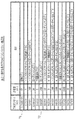
本技術分野で既知の米国のTV周波数帯を、VHF(Very High Frequency)帯域およびUHF(Ultra High Frequency)帯域のTVチャンネルの表である図1の表1に示す。各TVチャンネルでは、対応する割当周波数帯域の下端が示されている。例えば、TVチャンネル2は54MHz(数百万ヘルツ)から始まり、TVチャンネル37は608MHzから始まり、TVチャンネル68は794MHzから始まる。本技術分野で既知のように、各TVチャンネル、または帯域は、6MHzの帯域幅をもつ。したがって、TVチャンネル2は54MHzから60MHzの周波数帯(または範囲)をカバーし、TVチャンネル37は608MHzから614MHzまでの帯域をカバーし、TVチャンネル68は794MHzから800MHzまでの帯域をカバーするなどとなる。前述したように、WRANシステムは、TV周波数帯における使用されていないテレビジョン(TV)放送チャンネルを利用する。ここで、WRANシステムは、WRANシステムのために実際に利用可能なTV周波数帯の部分を判定するため、WRANエリアでこれらのTVチャンネルのうちのどれが実際にアクティブ(または「使用済み」)であるか判定するために「チャンネルセンシング」を行う。
US TV frequency bands known in the art are shown in Table 1 of FIG. 1, which is a table of TV channels in the VHF (Very High Frequency) band and the UHF (Ultra High Frequency) band. In each TV channel, the lower end of the corresponding assigned frequency band is shown. For example,
図1に示すTV周波数帯のほかに、特定のチャンネルにおける特定のATSC DTV信号はまた、NTSC信号、さらには、ATSC信号とともに配置された(すなわち、同じチャンネルにおける)、またはATSC信号に隣接する(例えば、すぐ下のチャンネル、またはすぐ上のチャンネルにある)他のATSC信号から影響を受ける。これは、様々な干渉条件により影響を受けるATSCパイロット信号と同様に、図2の表2に例示する。例えば、表2の第1行71は、別のNTSCまたはATSC信号からの、ともに配置されたまたは隣接する干渉がある場合、ATSCパイロット信号のHz単位の下端オフセットを示す。これは、前述のATSC規格で規定されたATSCパイロット信号に対応する、すなわちパイロット信号は特定のチャンネルの下端の上の309.44059KHz(数千ヘルツ)で生じる(図1の表1は、各チャンネルのMHz単位の下端値を示す)。しかし、表2の72と表示された行を参照すると、ともに配置されたNTSC信号がある場合、ATSCパイロット信号の下端オフセットが示されている。そのような状況では、ATSC受信機は、下端の上の338.065KHzであるATSCパイロット信号を受信する。NTSC放送およびATSC放送の文脈では、表2から可能なオフセットの総数は14であることがわかる。しかし、NTSC送信が中断された後は、可能なオフセットの総数は、図3の表3に例示する、許容差が10Hzの2つに減少する。
In addition to the TV frequency band shown in FIG. 1, a particular ATSC DTV signal on a particular channel is also located with the NTSC signal, and further with the ATSC signal (ie, on the same channel), or adjacent to the ATSC signal ( Affected by other ATSC signals (for example, in the channel immediately below or just above). This is illustrated in Table 2 of FIG. 2, as well as ATSC pilot signals that are affected by various interference conditions. For example, the
いずれのチャンネルセンシングも正確であることが重要であることから、受信機のタイミング基準か搬送波周波数基準のどちらかの正確さを上げることにより、信号検出技法またはチャンネルセンシング技法の性能を(これらの技法がコヒーレントであろうと非コヒーレントであろうと)向上させることができることが確認された。特に、受信機は、いくつかのチャンネルのうちの1つにチューニングし、受信された放送信号の関数として較正されるチューナ、およびチューナに結合し、放送信号がチャンネルのうちの少なくとも1つに存在するかどうかを検出する放送信号検出器を備える。そのような受信機の例示的な実施形態は、参照として既存のATSCチャンネルを使用するものとして説明する。しかし、本発明の概念は、そのように限定されない。 Because it is important that any channel sensing is accurate, increasing the accuracy of either the receiver timing reference or the carrier frequency reference improves the performance of the signal detection or channel sensing technique (these techniques It has been confirmed that it can be improved (whether coherent or non-coherent). In particular, the receiver is tuned to one of several channels and coupled to a tuner that is calibrated as a function of the received broadcast signal, and the broadcast signal is present on at least one of the channels A broadcast signal detector for detecting whether or not to do so. An exemplary embodiment of such a receiver is described as using an existing ATSC channel as a reference. However, the concept of the present invention is not so limited.
本発明の原理を組み込んだ例示的な地域無線ネットワーク(WRAN)システム200を図4に示す。WRANシステム200は、一定の地理的エリア(WRANエリア)(図4には示さず)にサービスを提供する。一般に、WRANシステムは、1つまたは複数の顧客宅内機器(CPE)250と通信する少なくとも1つの基地局(BS)205を備える。顧客宅内機器は固定でもよい。CPE250は、プロセッサを備えたシステムであり、図4に破線のボックスの形で示すプロセッサ290およびメモリ295によって表される1つまたは複数のプロセッサおよび関連メモリを備える。このようなシステムでは、コンピュータプログラムまたはソフトウェアは、プロセッサ290による実行のためにメモリ295に格納される。プロセッサ290は、1つまたは複数の内蔵プログラム制御プロセッサを示しており、これらは、送信機機能専用でなくてもよく、例えばプロセッサ290はCPE250の他の機能を制御してもよい。メモリ295は、任意の記憶装置、例えばランダムアクセスメモリ(RAM)、読出し専用メモリ(ROM)などを示しており、CPE250に内蔵および/または外付けでもよく、必要に応じて揮発性および/または非揮発性でもよい。アンテナ210および255を介してBS205とCPE250との間で通信を制御する物理層(PHY)は、例としてトランシーバ285を介したOFDMによる、例えばOFDMAであり、矢印211によって表示する。WRANネットワークに入るため、CPE250はまずBS210と「結合」してもよい。この結合の間に、CPE250は、制御チャンネル(図示せず)を介してBS205にCPE250の機能に基づいてトランシーバ285を介して情報を送信する。機能の報告には、例えば最小および最大送信電力、および送受信のため用意されたチャンネルリストが含まれる。ここで、CPE250は、WRANエリアでどのTVチャンネルがアクティブでないか判定するために本発明の原理による「チャンネルセンシング」を行う。その結果、WRAN通信で使用することができるチャンネルのリストが、BS205に提供される。
An exemplary regional wireless network (WRAN)
CPE250での使用のための受信機300の例示的な部分を図5に示す。受信機300の、本発明の原理に関連する部分だけが示されている。受信機300は、チューナ305、搬送波トラッキングループ(CTL)315、ATSC信号検出器320、およびコントローラ325を備える。コントローラ325は、1つまたは複数の内蔵プログラム制御プロセッサ、例えばマイクロプロセッサ(プロセッサ290など)を示しており、これらは本発明に専用でなくてもよく、例えばコントローラ325は受信機300の他の機能を制御してもよい。さらに、受信機300は、メモリ(メモリ295など)、例えばランダムアクセスメモリ(RAM)、読出し専用メモリ(ROM)などを備え、それらは、コントローラ325の一部分でも、またはそれとは別個とすることもできる。簡単のために、図5には、自動利得制御コンポーネント(AGC)、デジタルでの処理の場合はアナログデジタルコンバータ(ADC)、および追加のフィルタリングなど、いくつかのコンポーネントは示していない。本発明にかかわらず、これらのコンポーネントは当業者には容易に理解できるであろう。ここで、ここに記載されている諸実施形態は、アナログの世界でも、デジタルの世界でも実施することができる。さらに、これらの処理には、必要に応じて複素信号パスを必要とする可能性があることも当業者は理解するであろう。
An exemplary portion of a
本発明の原理を説明する前に、受信機300の一般的な動作は以下の通りである。(例えば、図4のアンテナ255を介して受信される)入力信号304を、チューナ305に入力する(apply)。入力信号304は、前述の「ATSCデジタルテレビジョン規格」に準拠し、図1の表1に示されているチャンネルのうちの1つで送信されるデジタルVSB変調信号を表す。チューナ305は、特定のTVチャンネルを選択し、特定のIF(中間周波数)を中心にして下方変換された信号306を供給するため、双方向信号パス326を介してコントローラ325により全チャンネルのうちの異なるチャンネルにチューニングされる。信号306は、(送信機の局部発振器(LO)と、受信機のLOとの間などの)いかなる周波数オフセットをも除去するため、および受信されたATSC VSB信号を中間周波数(IF)またはベースバンドの近くの周波数からベースバンドに復調するための両方のため、信号306を処理するCTL315に適用される(例えば、非特許文献2、およびWangの2001年5月15日発行の特許文献1、名称「Segment Sync Recovery Network for an HDTV Receiver」参照)。CTL315は信号316を、信号316がATSC信号かどうか判定するため、(以下でさらに説明する)信号316を処理するATSC信号検出器320に供給する。ATSC信号検出器320は、結果の情報を、パス321を介して、コントローラ325に提供する。
Before explaining the principle of the present invention, the general operation of the
次に、図6を参照すると、本発明の原理による受信機300で使用する例示的なフローチャートが示されている。特に、正確な搬送波およびタイミングオフセット情報を有することによって、使用可能な信号を復調するのに必要なレベルよりも低い信号レベルのVHFおよびUHF TV帯域内のATSC DTV信号が使用中か否かを検出することが容易になる。例として、DTVチャンネル自体の安定性および既知の(known)周波数割当がこの情報を提供するために使用される。上記のATSC A/54A ATSC Recommended Practiceに詳述されているように、搬送波周波数は、少なくとも1KHz(数千ヘルツ)以内にあるように指定され、より厳しい許容差が推奨されている。ここで、ステップ260でコントローラ325は、まず容易に識別可能な使用中のATSC信号があるか判定するため、図1の表1に例示されているような、既知のTVチャンネルをスキャンする。特に、コントローラ325は、各TVチャンネルを選択するためにチューナ305を制御する。結果得られた信号は(あれば)、(以下でさらに説明する)ATSC信号検出器320によって処理され、その結果がパス321を介してコントローラ325に提供される。好ましくは、コントローラ325は、WRANエリアで現在放送している最も強いATSC信号を探す。しかし、コントローラ325は、最初に検出されたATSC信号で停止してもよい。
Referring now to FIG. 6, an exemplary flowchart for use with a
図7を簡単に参照すると、チューナ305の例示的なブロック図が示されている。チューナ305は、増幅器355、乗算器360、フィルタ365、n除算(divide−by−n)コンポーネント370、電圧制御発振器(VCO)385、位相検出器375、ループフィルタ390、m除算コンポーネント380、および局部発振器(LO)395を備える。本発明にかかわらず、チューナ305のコンポーネントはよく知られているので、ここではさらには説明しない。一般に、LO395およびVCO385によって供給される信号間で以下の関係が維持される。
Referring briefly to FIG. 7, an exemplary block diagram of the

式中、FrefはLO395によって提供された基準周波数であり、FvcoはVCO385によって提供される周波数であり、nは、n除算コンポーネント370によって表される除数の値であり、mはm除算コンポーネント380によって表される除数の値である。等式(1)は、
Where F ref is the reference frequency provided by
と書き直すことができる。等式(2)から、Fvcoは、パス326を介してコントローラ325(図6のステップ260)によって設定される適切なnの値によって様々なATSC DTV帯域に設定することができることがわかる。しかし、上記のように、受信機300は、いかなる周波数オフセットFoffsetをも除去するCTL315を備える。重要な2つの周波数オフセットがある。1つは、LO395と送信機周波数基準との間の周波数の違いによって生じるエラーである。もう1つは、LO395によって提供される実際の周波数Frefは局部発振器の所与の許容差以内でおおよそ知られることから、Fstepのために使用される値によって生じるエラーである。したがって、Foffsetは、選択されたチャンネルに対するnFstepの値からのエラーと、局部周波数基準および送信機周波数基準における周波数の違いによって生じるエラーの両方を含む。
Can be rewritten. From equation (2), it can be seen that F vco can be set to various ATSC DTV bands with the appropriate value of n set by controller 325 (
次に図8を参照すると、CTL315の例示的なブロック図を示す。CTL315は、乗算器405、位相検出器410、ループフィルタ415、数値制御発振器(NCO)420、およびSin/Cos表425を備える。本発明にかかわらず、CTL315の構成はよく知られているので、ここではさらには説明しない。NCO420は本技術分野で知られているようにFoffsetを決定し、これらの周波数オフセットはSin/Cos表425および乗算器405を介して受信した信号から除去される。
Referring now to FIG. 8, an exemplary block diagram of
図6のステップ270を続けて、使用中のATSC信号を見つけた後は、コントローラ325は、検出されたATSC信号から少なくとも1つの関係周波数(タイミング)特性を決定することにより受信機300を較正する。特に、図5の受信機300の一般的動作は以下の等式によって表すことができる。
Continuing
![]()
![]()
式中、Fcは、ATSC信号のパイロット信号の周波数を表す。等式(3)内のFoffsetの値は、コントローラ325が双方向パス327を介してNCO内の関連するデータに単にアクセスすることにより決定する。しかし、nの値は選択されたATSCチャンネルのためにコントローラ325によってすでに決定されたが、実際のFstepの値は知られていない。しかし、等式(3)は、
In the equation, F c represents the frequency of the pilot signal of the ATSC signal. The value of F offset in equation (3) is determined by the
と書き直すことができる。このソリューションは、簡単なように見えるが、Fcの値は、図1の表1によって示唆されているように独自には決定されないことを思い出す必要がある。むしろ、検出されたATSC DTV信号は、図2の表2および図3の表3に示すように、他のNTSCまたはATSC信号の影響を受ける可能性がある。WRAN領域にNTSCおよびATSC送信がある場合、図2の表2に示すように14の可能なオフセットを考慮しなければならない。しかし、WRAN領域にNTSC送信がない場合、図3の表3に示すように2つのオフセットだけを考慮しなければならない。簡単のために、NTSC送信はなく、表3だけがこの実施例のために使用されると仮定される。 Can be rewritten. Although this solution seems simple, it should be recalled that the value of F c is not uniquely determined as suggested by Table 1 of FIG. Rather, the detected ATSC DTV signal may be affected by other NTSC or ATSC signals, as shown in Table 2 of FIG. 2 and Table 3 of FIG. If there are NTSC and ATSC transmissions in the WRAN area, 14 possible offsets must be considered as shown in Table 2 of FIG. However, if there is no NTSC transmission in the WRAN area, only two offsets must be considered as shown in Table 3 of FIG. For simplicity, there is no NTSC transmission and it is assumed that only Table 3 is used for this example.
したがって、コントローラ325は、(例えば、上記のメモリに格納された)表1および表3の値を使用してFstepの様々な値を決定するために2つの計算、
Thus, the
を行う。式中、 I do. Where
![]()
![]()
は、選択されたATSCチャンネルのための表1からの低帯域端、足す表3の第1行からの低帯域端オフセットを示しており、 Shows the low band edge from Table 1 for the selected ATSC channel, plus the low band edge offset from the first row of Table 3;
![]()
![]()
は、選択されたATSCチャンネルの表1からの低帯域端、足す表3の第2行からの低帯域端オフセットを表す。結果として、コントローラ325は、受信機300での使用のためのFstepの2つの可能な値を決定する。したがって、ステップ270で、コントローラ325は送信機300の較正で使用するためのチューニングパラメータを決定する。
Represents the low band edge from Table 1 of the selected ATSC channel, plus the low band edge offset from the second row of Table 3. As a result, the
最後に、ステップ275では、コントローラ325を使用していないので、WRAN通信をサポートするために利用可能である1つまたは複数のTVチャンネルを含む利用可能なチャンネルのリストを決定するためTV周波数帯がスキャンされる。コントローラ325によって(例えば、表1のリストから)選択された各チャンネルに関しては、式(3)、(4)、(4a)および(4b)に関する観察がさらに行われる。言い換えると、選択された各チャンネルに関しては、表3に示されているオフセットを考慮しなければならない。表3に示す2つのオフセットがあり、ステップ270で決定されたFstepの2つの可能な値(式(4a)および(4b))があるので、4つのスキャンを行わる(表2に記載されているオフセットが使用されれば、142スキャンまたは196スキャンとなるであろう)。例えば、第1のスキャンでは、コントローラ325が、パス326を介して、各ATSCチャンネルのためにnの様々な値をチューナ305に設定する。コントローラ325は、
Finally, in
からnおよびFoffsetの値を決定する。式中、Fstepの値は、 N and F offset values are determined. In the formula, the value of F step is
![]()
![]()
の決定された値に等しく、Fcの値は、選択されたATSCチャンネルのための表1からの低帯域端、足す表3の第1行からの低帯域端オフセットに等しい(式(5)内の「床」関数の代わりに、「天井」関数を使用することができることにも留意すべきである)。しかし、第2のスキャンでは、Fstepの値は、 And the value of F c is equal to the low-band edge from Table 1 for the selected ATSC channel, plus the low-band edge offset from the first row of Table 3 (equation (5)). It should also be noted that instead of the “floor” function in the “ceiling” function can be used). However, in the second scan, the value of F step is
![]()
![]()
の決定された値にそれでもなお等しいが、Fcの値は、今度は選択されたATSCチャンネルのための表1からの低帯域端、足す表3の第2行からの低帯域端オフセットに等しくなるように変えられている。第3スキャンおよび第4スキャンは、Fstepが今度は、 The value of F c is now equal to the low band edge offset from Table 1, plus the low band edge offset from the second row of Table 3, for the selected ATSC channel. It has been changed to become. In the third and fourth scans, F step is now
![]()
![]()
の決定された値に等しく設定されること以外は同様である。これらの各スキャン中、チューナ305は選択されたチャンネルを提供するようにチューニングされるので、ATSC検出器320は、ATSC信号が現在選択されているチャンネル上に使用中のかどうか判定するために受信した信号を処理する。ATSC信号の存在に関するデータまたは情報は、パス321を介してコントローラ325に提供される。この情報から、コントローラ325は利用可能なチャンネルリストを構築する。したがって、本発明の原理にしたがって、低SNR ATSC DTV信号の検出を向上するため、DTVチャンネル自体の安定および既知の周波数割当が受信機300を較正するために使用される。したがって、ステップ275で、受信機300は、ステップ270で決定された正確な周波数情報(Foffset、およびFstepの様々な値)のおかげで、非常に低いSNR環境でも存在する可能性があるATSC信号があるか否かを探索することができる。目標感度は、−116dBm(1ミリワットの電力レベルに対するデシベル)の信号強度のATSC信号を検出することである。これは、可視性の閾値(ToV)より30dB(デシベル)下より高い。局部発振器のドリフト特性に応じて、定期的に再較正することが必要であることに留意すべきである。前述の方法のさらなる変形の実施形態も実施することができることにも留意すべきである。例えば、ステップ260で検出されたATSC信号は、ステップ275で行われるスキャンから除外することができる。さらに、いかなる再較正も、再度ステップ260を実行することなく、ステップ260から識別されたATSC信号にチューニングすることにより直接行うことができる。さらに、ステップ275でATSC信号が検出された後、関連する帯域は、次に続くいかなるスキャンからも除外することができる。
It is the same except that it is set equal to the determined value of. During each of these scans,
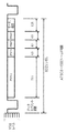
上記のように、受信機300は、ATSC信号検出器320を備える。ATSC信号検出器320の一実施例は、ATSC DTV信号のフォーマットを利用する。DTVデータは8−VSB(残留側波帯)を使用して変調される。特に、低SNR環境で動作する受信機では、ATSC DTV信号の中に埋め込まれたセグメント同期シンボルおよびフィールド同期シンボルが、ATSC DTV信号の存在を正確に検出する確率を上げるために受信機によって利用され、それによって誤警報確率を下げる。ATSC DTV信号では、8−レベルデジタルデータストリームのほかに、2−レベル(バイナリ)4−シンボルデータセグメント同期が各データセグメントの初めに挿入される。ATSCデータセグメントは図9に示す。ATSCデータセグメントは、832シンボル、すなわちデータセグメント同期のための4シンボルおよび828データシンボルからなる。データセグメント同期パターンは、図9からわかるようにバイナリ1001パターンである。複数のデータセグメント(313セグメント)は、合計260,416シンボル(832×313)を含むATSCデータフィールドを含む。データフィールド内のフィールドデータセグメントは、フィールド同期セグメントと呼ばれる。フィールド同期セグメントの構造は、図10に示されており、各シンボルはデータの1ビット(2レベル)を表す。フィールド同期セグメントでは、511ビット(PN511)の擬似ランダムシーケンスがデータセグメント同期のすぐ後に置かれる。PN511シーケンスの後に、ともに連結された3個の63ビットの同一の擬似ランダムシーケンス(PN63)があり、第2のPN63シーケンスは、データフィールド1つおきに反転される。
As described above, the
上記を考慮して、ATSC信号検出器320の一実施形態を図11に示す。この実施形態においては、ATSC信号検出器320は、PN511の存在を識別するために上記PN511シーケンスにマッチするマッチドフィルタ505を備える。他の変形の実施形態を図12に示す。この図では、マッチドフィルタからの出力は、突出したピークが存在するかどうか判定するために複数回累算される。これは、検出確率を上げ、誤警報確率を下げる。図12の実施形態の欠点は、大きなメモリが必要なことである。他の手法を図13に示す。この手法では、ピーク値が、1つのデータフィールドの中のその位置(510、515)と共に検出される(520)。リセット信号はまた、結果をRAM525の様々なロケーションに格納するために、アドレスカウンタを増分する(すなわち、「アドレスをバンプする」)ことに留意すべきである。したがって、その結果は、複数のデータフィールドのためにRAM525に格納される。ピークの位置がデータフィールドの一定の部分について同じである場合、そのDTVチャンネルでDTV信号が使用中と判定される。
In view of the above, one embodiment of an
ATSC DTV信号の存在を検出するための他の方法として、データセグメント同期を使用する方法が挙げられる。データセグメント同期は、データセグメントごとに繰り返すので、通常はタイミング回復のために使用される。このタイミング回復方法は、上記の非特許文献1で概説されている。しかし、データセグメント同期は、タイミング回復回路を使用してDTV信号の存在を検出するために使用することもできる。タイミング回復回路がタイミングロックを示す場合、それによりDTV信号の存在が確実に保証される。この方法は、クロックオフセットがタイミング回復回路のプルインレンジ内にある限り、初期局部シンボルクロックが送信機シンボルクロックの近くになくても有効である。しかし、有用なレンジは0dB SNRまでであったので、上記の−116dBmの検出目標に達するためには追加の15dBの改善が必要であることに留意すべきである。
Another method for detecting the presence of an ATSC DTV signal is to use data segment synchronization. Since data segment synchronization is repeated for each data segment, it is typically used for timing recovery. This timing recovery method is outlined in the above
ATSC信号を検出するために使用されることができる他の手法としては、利用されるタイミング回復機構と関係なくセグメント同期を処理する方法が考えられる。これは、図14に示すように、リーク積分器を含む無限インパルス応答(IIR)フィルタ550を使用するコヒーレントセグメント同期検出器を例示する(この場合、シンボルαは予め定義された定数である)。IIRフィルタを使用することによって、1つのセグメントの反復期間で生じる補強情報により検出するためタイミングピークが構築される。この場合、搬送波オフセットおよびタイミングオフセットは小さいと仮定している。
Another approach that can be used to detect the ATSC signal is to handle segment synchronization regardless of the timing recovery mechanism utilized. This illustrates a coherent segment sync detector using an infinite impulse response (IIR)
ATSC信号を検出するための上記のコヒーレントな方法以外に、非コヒーレントな手法を使用することができ、パイロット搬送波の使用によるベースバンドへの下方変換は必要とされない。これは、パイロットの強靭な抽出は低SNR環境では問題が多い可能性があるので有利である。1つの例示的な非コヒーレントセグメント同期検出器を、遅延線構造を例示する図15に示す。入力信号は、それ自体の遅延、共役と掛け合わされる(570、575)。その結果は、データセグメント同期にマッチするためのフィルタ(データセグメント同期マッチドフィルタ580)に入力される。共役は、いかなる搬送波オフセットもマッチドフィルタから生じる振幅に影響を与えないことを保証する。またはこれに代えて、「積分およびダンプ」手法を用いることができる。マッチドフィルタ580に続いて、信号の大きさ(585)が引かれる(または、より容易には、I2+Q2として2乗された大きさが引かれる。ただし、IおよびQは、それぞれマッチドフィルタからの信号の同相成分および直交成分である)。この大きさの値(586)は、DTV信号の存在を示す突出したピークが存在するかどうか見るために直接調べることができる。またはこれに代えて、図15に示すように、信号586は、複数のセグメントに関する推定の強靭性を改善するためにIIRフィルタ550で処理することによりさらに改善することができる。代替の実施形態を図16に示す。この実施形態においては、積分(580)がコヒーレントに(すなわち、位相情報を保持して)行われ、その後、信号の大きさ(585)が引かれる。
In addition to the above-described coherent methods for detecting ATSC signals, non-coherent techniques can be used, and no down-conversion to baseband by using pilot carriers is required. This is advantageous because robust extraction of pilots can be problematic in low SNR environments. One exemplary non-coherent segment sync detector is shown in FIG. 15, which illustrates a delay line structure. The input signal is multiplied by its own delay, conjugate (570, 575). The result is input to a filter for matching data segment synchronization (data segment synchronization matched filter 580). The conjugate ensures that any carrier offset does not affect the amplitude resulting from the matched filter. Alternatively, an “integration and dump” technique can be used. Following the matched
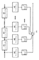
ベースバンドで実施する前述の実施形態と同様に、他の非コヒーレントの実施形態は、フィールド同期の中にある長い方のPN511シーケンスを利用してもよい。しかし、周波数オフセットに対応するために、いくつかの変更を行わなければならない可能性があることに留意すべきである。例えば、PN511シーケンスをATSC信号のインジケータとして使用する場合は、その存在を検出するために同時に使用するいくつかのコリレータがあってもよい。周波数オフセットが、搬送波がPN511シーケンス中に1つの完全なサイクルまたは回転を経験するようなものである場合を考察する。そのような場合、入力信号と基準PN511シーケンスとの間のマッチドコリレータ出力は、合計ゼロになるであろう。しかし、PN511シーケンスがN部分に分割された場合、各部分は、搬送波は各部分中に1/Nサイクルだけ回転するだけであろうから、かなりのエネルギを有するであろう。したがって、非コヒーレントコリレータ手法は、長いコリレータをより小さいシーケンスに分割し、図17に示すように、非コヒーレントコリレータを有する各サブシーケンスにアプローチすることにより利用されることができるてんで有利である。この図では、相関されるべきシーケンスは、0からN−1までの番号をつけられたNサブシーケンスに分割される。入力データは、コリレータ出力を使用可能な非コヒーレントな組み合わせを生成するために組み合わせる(590)ように遅延を付与される。 Similar to the previous embodiment implemented in baseband, other non-coherent embodiments may utilize the longer PN511 sequence that is in field synchronization. However, it should be noted that some changes may have to be made to accommodate the frequency offset. For example, when using a PN511 sequence as an indicator of an ATSC signal, there may be several correlators that are used simultaneously to detect its presence. Consider the case where the frequency offset is such that the carrier experiences one complete cycle or rotation during the PN511 sequence. In such a case, the matched correlator output between the input signal and the reference PN511 sequence will total zero. However, if the PN511 sequence is divided into N parts, each part will have significant energy because the carrier will only rotate 1 / N cycle in each part. Thus, the non-coherent correlator technique is advantageous in that it can be utilized by dividing a long correlator into smaller sequences and approaching each sub-sequence with non-coherent correlators as shown in FIG. In this figure, the sequence to be correlated is divided into N subsequences numbered from 0 to N-1. The input data is delayed to combine 590 to produce a non-coherent combination that can use the correlator output.
ATSC信号検出器の他の例示的な実施形態を図18に示す。ATSC信号検出器の複雑さを低減するために、図18のATSC信号検出器は、PN63シーケンスにマッチするマッチドフィルタ(710)を使用する。マッチドフィルタ710からの出力信号は遅延線715に適用される。図18の実施形態においては、コヒーレントを組み合わせる手法を使用する。中央のPN63はデータフィールド同期1つおきに変換されるので、2つの出力y1およびy2が、これらの2つのデータフィールド同期の場合に対応する加算器720および725によって生成される。図18からわかるように、出力y1のための処理パスは、加算器720による結合の前に中央のPN63を変換するための乗算器を含む。図18に示す実施形態はピーク検出を行うことに留意すべきである。突出したピークがy1かy2のどちらかに現れている場合は、ATSC DTV信号が使用中と推定される。
Another exemplary embodiment of an ATSC signal detector is shown in FIG. In order to reduce the complexity of the ATSC signal detector, the ATSC signal detector of FIG. 18 uses a matched filter (710) that matches the PN63 sequence. An output signal from the matched
PN63にマッチするATSC信号検出器の代替の実施形態を図19に示す。この実施形態は、マッチドフィルタ710の出力信号がまず信号の2乗の大きさを計算するコンポーネント730に入力されること以外は、図18に示されているものと同様である。これは非コヒーレントを組み合わせる手法の実施例である。図18の場合と同様に、図19の実施形態はピーク検出を行う。加算器735は、出力信号y3を提供するために遅延線715の様々な要素を組み合わせる。突出したピークがy3に現れている場合、ATSC DTV信号が使用中と推定される。搬送波オフセットが比較的大きい場合、図19の非コヒーレントを組み合わせる手法は、コヒーレントを組み合わせる手法より適切であることに留意すべきである。さらに、コンポーネント730は信号の大きさを単に判定することができることにも留意すべきである。
An alternative embodiment of an ATSC signal detector that matches PN63 is shown in FIG. This embodiment is similar to that shown in FIG. 18 except that the output signal of the matched
さらに追加の変形の実施形態を図20および21に示す。これらの例示的な実施形態においては、PN511およびPN63シーケンスは、ATSC信号検出のためにともに使用される。まず図20に示されている実施形態を参照すると、信号y1およびy2は、PN63シーケンスを検出するための図18の実施形態に関して前述したように生成される。さらに、(PN511にマッチする)マッチドフィルタ505からの出力は、3つのPN63シーケンスのための時間間隔に関するデータを格納する遅延線770に入力される。図20の実施形態はピーク検出を行う。突出したピークが(それぞれ加算器760および765によって提供された)z1かz2のどちらかに現れている場合、ATSC DTV信号が使用中と推定される。
Further additional variation embodiments are shown in FIGS. In these exemplary embodiments, the PN511 and PN63 sequences are used together for ATSC signal detection. Referring first to the embodiment shown in FIG. 20, signals y1 and y2 are generated as described above with respect to the embodiment of FIG. 18 for detecting a PN63 sequence. In addition, the output from the matched filter 505 (matching PN511) is input to a
図21を参照すると、図21の実施形態も、図19に示すように、PN511シーケンスの検出結果をPN63シーケンスの検出結果と組み合わせる。この実施形態のおいては、マッチドフィルタ505の出力信号はまず、信号の2乗の大きさを計算するコンポーネント780に入力される。これは、他の非コヒーレントを組み合わせる手法の実施例である。図20の場合と同様に、図21の実施形態はピーク検出を行う。加算器785は、出力信号z3を供給するため、遅延線770の様々な要素を出力信号y3と組み合わせる。突出したピークがz3に現れている場合、ATSC DTV信号が使用中と推定される。さらに、コンポーネント780は信号の大きさを単に判定することができることに留意すべきである。
Referring to FIG. 21, the embodiment of FIG. 21 also combines the detection result of the PN511 sequence with the detection result of the PN63 sequence, as shown in FIG. In this embodiment, the output signal of the matched
上記に対する他の変形の実施形態も可能である。例えば、PN63およびPN511マッチドフィルタは、必要とされる追加の遅延線の量を低減すべくそれらの固有の遅延線構造を利用するため、カスケードすることができる。他の実施形態においては、単一のPN63マッチドフィルタ足す遅延線ではなく、3つのPN63マッチドフィルタを利用することができる。これは、PN511マッチドフィルタを使用し、または使用せずに行うことができる。 Other variations on the above are possible. For example, PN63 and PN511 matched filters can be cascaded to take advantage of their inherent delay line structure to reduce the amount of additional delay line required. In other embodiments, three PN63 matched filters may be utilized rather than a single PN63 matched filter plus delay line. This can be done with or without a PN511 matched filter.
上記のように、WRANは、TV放送などの使用中の既存の信号帯に干渉しないことが必要である。したがって、WRANエンドポイントは、既存のTV信号が存在しないチャンネルを使用する。しかし、チャンネルにTV信号がなくても−TV信号は隣接するチャンネル上に存在する可能性がある。したがって、WRANエンドポイントからの送信信号は、それでもなお、非線形効果(例えば、混変調積)を導入することにより隣接するTV信号に干渉する可能性がある。ここで、無線エンドポイントは、隣接するチャンネルのTV放送に干渉するのを回避するために送信電力制御(TPC)を行う。特に、本発明の原理によって、無線エンドポイントは、チャンネルで信号を送信し、隣接するチャンネルでの信号の検出時に、送信される信号の電力レベルを調節する。 As described above, WRAN needs not to interfere with existing signal bands in use such as TV broadcasting. Therefore, the WRAN endpoint uses a channel for which no existing TV signal exists. However, even if there is no TV signal on the channel, the -TV signal may be on an adjacent channel. Thus, the transmitted signal from the WRAN endpoint may still interfere with adjacent TV signals by introducing non-linear effects (eg, cross modulation products). Here, the wireless endpoint performs transmission power control (TPC) in order to avoid interfering with the TV broadcast of the adjacent channel. In particular, according to the principles of the present invention, a wireless endpoint transmits a signal on a channel and adjusts the power level of the transmitted signal upon detection of a signal on an adjacent channel.
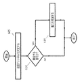
本発明の原理による例示的なフローチャートを図22に示す。ステップ605で、CPE250は、送信のために使用するチャンネルを決定する。CPE250は、どのチャンネルを使用するか決定するため、前述の利用可能なチャンネルリストからチャンネルを選択するか、それともBS205と交渉することができる。送信のためのチャンネルが選択された後、CPE250は、ステップ610で、既存の信号帯が隣接するチャンネル上に(現在選択されている送信チャンネルの上か下のどちらかに)使用中かどうか判定する。CPE250は、既存の信号帯が隣接するチャンネルに存在するかどうか、いくつものやり方で判定することができる。例えば、CPE250は、利用可能なチャンネルのリストを単にチェックすることができる。隣接するチャンネルが利用可能であると表示された場合、CPE250は、隣接するチャンネルに既存の信号帯はないと推定することができる。しかし、隣接するチャンネルがいずれも利用可能であると表示されない場合、CPE250は、隣接するチャンネルに既存の信号帯が使用中と推定することができる。またはこれに代えて、CPE250が隣接するチャンネルでチャンネルセンシングを行うようにすることができる。
An exemplary flowchart in accordance with the principles of the present invention is shown in FIG. In
ステップ610で、既存の信号帯が隣接するチャンネルで使用中と判定された場合、CPE250は、ステップ615で、その送信する信号の電力レベルを低減する。例えば、TV放送のD/U(所望対妨害)信号電力比が20dB(デシベル)である場合、隣接するTV放送の検出時に、WRANエンドポイントはその送信電力を20dBだけ低減する。図23を簡単に参照すると、トランシーバ285での使用のためのOFDM変調器650の例示的な実施形態が示されている。本発明の原理によれば、OFDM変調器650は、データ担持信号を表す信号649を受信し、選択された送信チャンネル上での放送のため、このデータ担持信号を変調する。結果としてのOFDM信号651の送信電力レベルは、例えば図4のプロセッサ295からの信号648によって制御される。
If it is determined in
さらに、図22は、本発明の概念に関係する送信電力制御の部分のみを示しているだけであることに留意すべきである。CPE250が隣接する既存の信号帯の信号を検出しないからといって、CPE250が他の手法による送信電力制御を行わないということは必ずしもない。例えば、BSおよびCPEは、経路損失、リンクマージン推定値、チャンネル測定結果、送信電力抑制など、いかなる基準に基づいてでも送信電力を動的に適応させることができる。
Furthermore, it should be noted that FIG. 22 shows only the portion of transmit power control that is relevant to the inventive concept. Just because the
さらに、BSはCPEに送信電力およびリンクマージン情報を報告するように要求してもよい。これは図24のメッセージのフローチャートに例示されている。BS205は、TPC要求681をCPE250に送信する。CPE250はTPC報告682で応答する。TPC報告での使用のためのいくつかの例示的な情報要素を図25に示す。TPC報告682は、2つの情報要素(IE)、すなわち送信電力IE687および推定リンクマージンIE686を含む。したがって、CPE250からの送信信号の電力レベルおよび推定リンクマージンは、別の無線エンドポイントに送信される。同様に、CPEは、BSに送信電力およびリンクマージン情報を報告するように要求するためTPC要求メッセージを使用してもよい。これは、図26のメッセージのフローチャートに例示している。CPE250は、TPC要求691をBS205に送信する。BS205は、TPC報告692で応答する。さらに、BSは、チャンネル環境の変化に応じてCPEの最大許容送信電力を変更するため制御メッセージ(図示せず)をCPEに出してもよい。
In addition, the BS may request the CPE to report transmission power and link margin information. This is illustrated in the message flow chart of FIG. The
(前述のTPC要求およびTPC報告などの)BS205と、CPE250との間の情報を通信で使用するための例示的なフレーム100を図27に示す。本発明にかかわらず、フレーム100は、非特許文献3に記載されているようなOFDMフレームと同様である。フレーム100は、同じ周波数帯域がアップリンク(UL)およびダウンリンク(DL)送信のために使用される時分割複信(TDD)システムのものを表している。本明細書では、アップリンクは、CPE250からBS205への通信を指し、ダウンリンクは、BS205からCPE250への通信を指す。各フレームは、2つのサブフレーム、すなわちDLサブフレーム101およびULサブフレーム102を含む。各フレームには、BS205が折り返す(すなわち、送信から受信に、および逆に切り替わる)ことができるようにするため時間間隔が含まれている。これらは、図27では、RTG(受信/送信遷移ギャップ)間隔およびTTG(送信/受信遷移ギャップ)間隔として示されている。各サブフレームはいくつかのバーストでデータを搬送する。フレーム、ならびにDLサブフレーム内のDLバーストの数およびULサブフレーム内のULバーストの数についての情報は、フレーム制御ヘッダ(FCH)77、DL MAP78、およびUL MAP79で搬送される。各フレームはまた、フレーム同期化および等化を行なうためのプリアンブル76を含む。
An
前述のように、WRANシステムの性能は、無線エンドポイントが隣接するチャンネル上での既存の信号帯の信号の検出時に、その送信電力レベルを低減するような送信電力制御機構を使用することにより向上させることができる。本発明の概念は、図4のCPE250の文脈で説明されたが、本発明は、そのように限定されず、例えばBS205にも適用されることに留意すべきである。さらに、チャンネルセンシングは、図5から8に例示されている技法にそって説明したが、本発明の概念はまた、そのように限定されない。チャンネルセンシングの他の形態が使用することができる。例えば、CPE250での使用のための受信機805の例示的な部分を図28に(例えば、トランシーバ285の一部分として)示す。本発明の概念に関連する受信機805は必要な部分だけを示している。受信機805は、チューナ810、信号検出器815、およびコントローラ825を備える。コントローラ825は、1つまたは複数の内蔵プログラム制御プロセッサ、例えばマイクロプロセッサ(プロセッサ290など)を示しており、これらは本発明専用でなくてもよく、例えばコントローラ825は、受信機805の他の機能を制御することもできる。さらに、受信機805は、メモリ(メモリ295など)、例えばランダムアクセスメモリ(RAM)、読出し専用メモリ(ROM)などを備え、それらはコントローラ825の一部分でもよく、またはそれとは別個のものでもよい。簡単のために、図28には、オートゲインコントロール(AGC)コンポーネント、処理がデジタルの場合はアナログデジタルコンバータ(ADC)、および追加のフィルタリングなど、いくつかのコンポーネントは示していない。本発明にかかわらず、これらの要素は当業者には容易に明らかであろう。ここで、本明細書に記載の諸実施形態は、アナログでも、またはデジタルでも実施することができる。さらに、処理には、必要に応じて複素信号パスを必要とする場合があることも当業者は理解するであろう。チャンネルセンシングの説明に沿って、チューナ810は、特定のTVチャンネルを選択するため、双方向信号パス826を介してコントローラ825によって様々なチャンネルにチューニングされる。選択されたチャンネルごとに、入力信号804が存在する可能性がある。入力信号804は、前述の「ATSCデジタルテレビジョン規格」によるデジタルVSB変調信号などの既存の広帯域信号、NTSC TV信号、または既存の狭帯域信号を表してもよい。選択されたチャンネルに既存の信号帯の信号がある場合、チューナ810は、信号806が広帯域既存の信号帯の信号か狭帯域既存の信号帯の信号か判定するために信号806を処理する信号検出器815に、下方変換された信号806を供給する。信号検出器815は、パス816を介してコントローラ825に結果の情報を提供する。したがって、本発明の概念は、隣接するチャンネルに使用中の可能性がある広帯域(例えばNTSC)または狭帯域のいかなる信号の検索にも適用される。ここで、送信電力レベルは、図22のステップ615で、隣接する既存の信号帯の信号のタイプに応じて様々な量だけ調整することができる。
As mentioned above, the performance of a WRAN system is improved by using a transmission power control mechanism that reduces the transmission power level when a wireless endpoint detects a signal in an existing signal band on an adjacent channel. Can be made. It should be noted that although the concept of the present invention has been described in the context of
上記を考慮して、前述の説明は本発明の原理を例示するだけであり、したがって、当業者は、本明細書に明示的に記載されていなくても、本発明の原理を実施し本発明の趣旨と範囲の中にある多くの代替の実施形態を考案することができるであろうことが、理解されるであろう。例えば、これらの機能要素は、別個の機能要素の説明に沿って例示されているが、1つまたは複数の集積回路(IC)で実施することができる。同様に、これらの要素のうちのいずれかまたは全ては、別個の要素として示されているが、関連ソフトウェア、例えば図22などに示されているステップの1つまたは複数のステップに対応するソフトウェアを実行する内蔵プログラム制御プロセッサ、例えばデジタル信号プロセッサで実行することができる。さらに、本発明の原理は、他のタイプの通信システム、例えば、衛星、ワイヤレスフィデリティ(Wi−Fi)、セルラなどに適用可能である。実際、本発明の概念はまた、固定受信機または移動受信機に適用可能である。したがって、例示的な実施形態に対して多くの変更を行ってもよく、特許請求の範囲によって規定された本発明の趣旨および範囲から逸脱することなく他の構成が考案することができることが理解される。 In view of the above, the foregoing description is only illustrative of the principles of the invention and, therefore, those skilled in the art will implement the principles of the invention and do not It will be understood that many alternative embodiments may be devised which are within the spirit and scope of the present invention. For example, these functional elements are illustrated along with a description of separate functional elements, but can be implemented in one or more integrated circuits (ICs). Similarly, any or all of these elements are shown as separate elements, but associated software, such as software corresponding to one or more of the steps shown in FIG. It can be executed by a built-in program control processor that executes, for example, a digital signal processor. Furthermore, the principles of the present invention are applicable to other types of communication systems, such as satellites, wireless fidelity (Wi-Fi), cellular, and the like. In fact, the inventive concept is also applicable to fixed or mobile receivers. Accordingly, it will be understood that many modifications may be made to the exemplary embodiments and that other configurations may be devised without departing from the spirit and scope of the invention as defined by the claims. The
Claims (12)
チャンネルで信号を送信するステップと、
隣接するチャンネルに信号があるかどうか判定するステップと、
隣接するチャンネルに信号があると判定された場合、前記送信される信号の電力レベルを調整するステップと
を備えたことを特徴とする方法。 A method for use with a wireless endpoint,
Transmitting a signal on the channel;
Determining whether there is a signal in an adjacent channel;
Adjusting the power level of the transmitted signal when it is determined that there is a signal in an adjacent channel.
送信チャンネル内の直交周波数分割多重(OFDM)で信号を送信するための変調器と、
前記送信チャンネルに隣接するチャンネルに信号がある否かを判定する機能として、前記変調器の電力レベルを制御するプロセッサと
を備えたことを特徴とする機器。 A device used in a wireless endpoint,
A modulator for transmitting signals in orthogonal frequency division multiplexing (OFDM) within a transmission channel;
An apparatus comprising: a processor that controls a power level of the modulator as a function of determining whether or not there is a signal in a channel adjacent to the transmission channel.
前記プロセッサは、信号が隣接するチャンネルにあるかどうか判定するために、前記格納された利用可能なチャンネルのリストをチェックすることを特徴とする請求項7に記載の機器。 A memory for storing a list of available channels;
8. The apparatus of claim 7, wherein the processor checks the stored list of available channels to determine if a signal is on an adjacent channel.
前記チューナに結合され、隣接するチャンネルに信号があるかどうかを判定する信号検出器と
をさらに備えたことを特徴とする請求項7に記載の機器。 A tuner that tunes to one of multiple channels;
The apparatus of claim 7, further comprising: a signal detector coupled to the tuner for determining whether there is a signal on an adjacent channel.
Applications Claiming Priority (2)
| Application Number | Priority Date | Filing Date | Title |
|---|---|---|---|
| US73412305P | 2005-11-07 | 2005-11-07 | |
| PCT/US2006/042849 WO2007056081A1 (en) | 2005-11-07 | 2006-11-01 | Apparatus and method for transmit power control frequency selection in wireless networks |
Publications (1)
| Publication Number | Publication Date |
|---|---|
| JP2009515481A true JP2009515481A (en) | 2009-04-09 |
Family
ID=37820575
Family Applications (3)
| Application Number | Title | Priority Date | Filing Date |
|---|---|---|---|
| JP2008539035A Pending JP2009515436A (en) | 2005-11-07 | 2006-11-01 | Apparatus and method for performing dynamic frequency selection in an OFDM network |
| JP2008540064A Withdrawn JP2009515479A (en) | 2005-11-07 | 2006-11-01 | Apparatus and method for dynamic frequency selection in a wireless network |
| JP2008540078A Withdrawn JP2009515481A (en) | 2005-11-07 | 2006-11-01 | Apparatus and method for selecting frequency for transmission power control in wireless network |
Family Applications Before (2)
| Application Number | Title | Priority Date | Filing Date |
|---|---|---|---|
| JP2008539035A Pending JP2009515436A (en) | 2005-11-07 | 2006-11-01 | Apparatus and method for performing dynamic frequency selection in an OFDM network |
| JP2008540064A Withdrawn JP2009515479A (en) | 2005-11-07 | 2006-11-01 | Apparatus and method for dynamic frequency selection in a wireless network |
Country Status (9)
| Country | Link |
|---|---|
| US (3) | US20090286565A1 (en) |
| EP (3) | EP1952550A1 (en) |
| JP (3) | JP2009515436A (en) |
| KR (3) | KR20080065275A (en) |
| CN (3) | CN101300746A (en) |
| BR (3) | BRPI0618299A2 (en) |
| CA (3) | CA2627437A1 (en) |
| TW (3) | TW200729772A (en) |
| WO (3) | WO2007056081A1 (en) |
Cited By (4)
| Publication number | Priority date | Publication date | Assignee | Title |
|---|---|---|---|---|
| JP2012527144A (en) * | 2009-05-14 | 2012-11-01 | コーニンクレッカ フィリップス エレクトロニクス エヌ ヴィ | Robust detection of DVB-T / H communication in the presence of frequency offset |
| JP2014509144A (en) * | 2011-02-16 | 2014-04-10 | クゥアルコム・インコーポレイテッド | Managing transmit power and modulation and coding scheme selection during random access in TV white space |
| US9585025B2 (en) | 2011-02-16 | 2017-02-28 | Qualcomm Incorporated | Managing transmit power for better frequency re-use in TV white space |
| US9813994B2 (en) | 2011-02-16 | 2017-11-07 | Qualcomm, Incorporated | Managing transmit power for better frequency re-use in TV white space |
Families Citing this family (45)
| Publication number | Priority date | Publication date | Assignee | Title |
|---|---|---|---|---|
| US7231232B2 (en) | 2002-02-13 | 2007-06-12 | Osann Jr Robert | Courtesy answering solution for wireless communication devices |
| EP1739908A1 (en) * | 2005-06-30 | 2007-01-03 | STMicroelectronics N.V. | Method and apparatus for reducing the interferences between a wide band device and a narrow band interferer |
| EP1739909A1 (en) * | 2005-06-30 | 2007-01-03 | STMicroelectronics N.V. | Method and apparatus for reducing the interferences between a wide band device and a narrow band device interfering with said wide band device |
| CN101300746A (en) * | 2005-11-07 | 2008-11-05 | 汤姆森许可贸易公司 | Apparatus and method for transmit power control frequency selection in wireless networks |
| KR100965655B1 (en) * | 2006-03-06 | 2010-06-23 | 삼성전자주식회사 | Method for transmitting/receiving signal in a communication system |
| US8688759B2 (en) | 2006-06-16 | 2014-04-01 | Bae Systems Information And Electronic Systems Integration Inc. | Efficient detection algorithm system for a broad class of signals using higher-order statistics in time as well as frequency domains |
| US8031618B2 (en) * | 2006-10-16 | 2011-10-04 | Stmicroelectronics, Inc. | Methods of RF sensing control and dynamic frequency selection control for cognitive radio based dynamic spectrum access network systems-cognitive dynamic frequency hopping |
| US7706465B2 (en) * | 2006-12-05 | 2010-04-27 | Motorola, Inc. | Method and apparatus for communication by a secondary user of spectrum |
| US8687563B2 (en) * | 2007-01-09 | 2014-04-01 | Stmicroelectronics, Inc. | Simultaneous sensing and data transmission |
| KR101390110B1 (en) * | 2007-02-22 | 2014-04-28 | 삼성전자주식회사 | Apparatus and method for transmitting and receiving a signal in a communication system |
| FR2916919B1 (en) * | 2007-05-31 | 2009-09-04 | Commissariat Energie Atomique | OPPORTUNISTIC RADIO TERMINAL |
| US20080309829A1 (en) * | 2007-06-14 | 2008-12-18 | Koninklijke Philips Electronics, N.V. | Frequency selective radio sensor and a method thereof |
| WO2008153553A1 (en) * | 2007-06-15 | 2008-12-18 | Thomson Licensing | Detection of signals containing sine-wave components through measurement of the power spectral density (psd) and cyclic spectrum |
| EP2171485A4 (en) | 2007-07-12 | 2018-01-10 | BAE Systems Information and Electronic Systems Integration Inc. | Spectrum sensing function for cognitive radio applications |
| CN101690061B (en) * | 2007-07-13 | 2013-05-22 | 汤姆森许可贸易公司 | Spectrum sensing for OFDM signals by utilizing pilot tones |
| WO2009057083A2 (en) * | 2007-10-31 | 2009-05-07 | Zion Hadad | Cognitive network |
| CN102007743B (en) * | 2008-02-13 | 2015-04-08 | 电视广播有限公司 | Band-efficient method and system for transmitting/receiving a communication signal using a channel band |
| US8059676B2 (en) | 2008-02-17 | 2011-11-15 | Lg Electronics Inc. | Method of communication using frame |
| US8411766B2 (en) | 2008-04-09 | 2013-04-02 | Wi-Lan, Inc. | System and method for utilizing spectral resources in wireless communications |
| US7906048B2 (en) | 2008-04-23 | 2011-03-15 | Koalesce, Inc. | Injection molding method and apparatus |
| US9219458B2 (en) * | 2008-06-12 | 2015-12-22 | Qualcomm Incorporated | Methods and systems of AGC and DC calibration for OFDM/OFDMA systems |
| US8451917B2 (en) | 2008-06-30 | 2013-05-28 | Motorola Solutions, Inc. | Method and apparatus for detection of orthogonal frequency division multiplexing (OFDM) signals by cognitive radios |
| US8274885B2 (en) | 2008-10-03 | 2012-09-25 | Wi-Lan, Inc. | System and method for data distribution in VHF/UHF bands |
| US8107391B2 (en) | 2008-11-19 | 2012-01-31 | Wi-Lan, Inc. | Systems and etiquette for home gateways using white space |
| US8630212B2 (en) | 2008-11-27 | 2014-01-14 | Lg Electronics Inc. | Apparatus and method for data transmission in wireless communication system |
| US9154273B2 (en) * | 2008-12-22 | 2015-10-06 | Lg Electronics Inc. | Method and apparatus for data transmission using a data frame |
| JP5645847B2 (en) | 2009-01-22 | 2014-12-24 | ウィ−ラン インコーポレイテッド | Method and system for detecting usable spectrum in a wireless communication system |
| US8335204B2 (en) * | 2009-01-30 | 2012-12-18 | Wi-Lan, Inc. | Wireless local area network using TV white space spectrum and long term evolution system architecture |
| US8937872B2 (en) | 2009-06-08 | 2015-01-20 | Wi-Lan, Inc. | Peer-to-peer control network for a wireless radio access network |
| CN101938284B (en) * | 2009-06-30 | 2014-01-01 | 深圳富泰宏精密工业有限公司 | Communication device and communication method thereof |
| CN102484845B (en) * | 2009-09-09 | 2015-11-25 | Lg电子株式会社 | Channel scanning method in wireless local area network (WLAN) system |
| JP5329389B2 (en) * | 2009-12-28 | 2013-10-30 | 株式会社ウィルコム | Frequency resource allocation method and system for wireless communication system |
| JP2011150583A (en) * | 2010-01-22 | 2011-08-04 | Sony Corp | Image display device having imaging device |
| GB2479173A (en) | 2010-03-31 | 2011-10-05 | Sony Corp | Reducing interference at a television receiver by identifying channel maps |
| CN101867390A (en) * | 2010-05-04 | 2010-10-20 | 中兴通讯股份有限公司 | Anti-interference method and system for mobile communication terminal |
| KR101455841B1 (en) * | 2010-11-08 | 2014-11-03 | 한국전자통신연구원 | Frequency sensing method and apparatus for ofdm system |
| US9048994B2 (en) * | 2011-04-18 | 2015-06-02 | Broadcom Corporation | Downclocking and/or adaptive sub-carriers for single user, multiple user, multiple access, and/or MIMO wireless communications |
| CN103095633B (en) * | 2011-11-04 | 2016-03-02 | 上海瀚讯无线技术有限公司 | The method of arrowband interference is resisted in OFDM communication system |
| US9967130B2 (en) * | 2012-05-21 | 2018-05-08 | Sony Corporation | Devices and methods for dynamic broadcast |
| US20140044150A1 (en) | 2012-08-13 | 2014-02-13 | Redline Communications, Inc. | System and method for interference triggered frequency hopping |
| US9667315B2 (en) | 2012-09-05 | 2017-05-30 | Landis+Gyr Technologies, Llc | Power distribution line communications with compensation for post modulation |
| US9306624B1 (en) | 2015-03-31 | 2016-04-05 | Landis+Gyr Technologies, Llc | Initialization of endpoint devices joining a power-line communication network |
| US9461707B1 (en) | 2015-05-21 | 2016-10-04 | Landis+Gyr Technologies, Llc | Power-line network with multi-scheme communication |
| US9930394B2 (en) * | 2015-06-01 | 2018-03-27 | Bby Solutions, Inc. | Display component activation |
| US10200993B2 (en) * | 2016-04-29 | 2019-02-05 | Qualcomm Incorporated | Techniques for performing a distributed channel availability check in a shared radio frequency spectrum band |
Family Cites Families (39)
| Publication number | Priority date | Publication date | Assignee | Title |
|---|---|---|---|---|
| US5959699A (en) * | 1994-06-28 | 1999-09-28 | Samsung Electronics Co., Ltd. | Reception mode control in radio receivers for receiving both VSB and QAM digital television signals |
| US5726978A (en) * | 1995-06-22 | 1998-03-10 | Telefonaktiebolaget L M Ericsson Publ. | Adaptive channel allocation in a frequency division multiplexed system |
| US5982457A (en) * | 1997-01-07 | 1999-11-09 | Samsung Electronics, Co. Ltd. | Radio receiver detecting digital and analog television radio-frequency signals with single first detector |
| DE19800953C1 (en) * | 1998-01-13 | 1999-07-29 | Siemens Ag | Resource allocation in radio interface of radio communications system |
| US6483869B1 (en) * | 1998-09-30 | 2002-11-19 | 3Com Corporation | Frequency decimated DMT modulation modem |
| JP4147647B2 (en) * | 1998-11-09 | 2008-09-10 | ソニー株式会社 | Data processing apparatus, data processing method, and recording medium |
| US6665349B1 (en) * | 1999-01-11 | 2003-12-16 | International Business Machines Corporation | Filtered multitone transmission application to DSL technologies |
| US6628673B1 (en) * | 1999-12-29 | 2003-09-30 | Atheros Communications, Inc. | Scalable communication system using overlaid signals and multi-carrier frequency communication |
| US7248841B2 (en) * | 2000-06-13 | 2007-07-24 | Agee Brian G | Method and apparatus for optimization of wireless multipoint electromagnetic communication networks |
| WO2002003567A2 (en) * | 2000-06-21 | 2002-01-10 | Cornell Research Foundation, Inc. | Adaptive power control for wireless networks |
| DE10035041B4 (en) * | 2000-07-19 | 2006-07-13 | Robert Bosch Gmbh | Method for setting transmission parameters from a transmitter for digital broadcasting signals |
| US6721569B1 (en) * | 2000-09-29 | 2004-04-13 | Nortel Networks Limited | Dynamic sub-carrier assignment in OFDM systems |
| US6990087B2 (en) * | 2002-04-25 | 2006-01-24 | Raytheon Company | Dynamic wireless resource utilization |
| JP3576099B2 (en) * | 2000-12-22 | 2004-10-13 | 株式会社東芝 | Receiver using smart antenna, receiving method using smart antenna, and beam forming circuit |
| US20020172186A1 (en) * | 2001-04-09 | 2002-11-21 | Peter Larsson | Instantaneous joint transmit power control and link adaptation for RTS/CTS based channel access |
| US7158759B2 (en) * | 2001-04-13 | 2007-01-02 | Broadcom Corporation | Dynamic frequency selection in a wireless communication network |
| US7206840B2 (en) * | 2001-05-11 | 2007-04-17 | Koninklike Philips Electronics N.V. | Dynamic frequency selection scheme for IEEE 802.11 WLANs |
| US7120138B2 (en) * | 2001-07-02 | 2006-10-10 | Koninklijke Philips Electronics N.V. | Dynamic frequency selection with recovery for a basic service set network |
| US6697013B2 (en) * | 2001-12-06 | 2004-02-24 | Atheros Communications, Inc. | Radar detection and dynamic frequency selection for wireless local area networks |
| JP3882665B2 (en) * | 2002-04-17 | 2007-02-21 | ソニー株式会社 | COMMUNICATION DEVICE, RECEPTION DEVICE, AND COMMUNICATION METHOD FOR RADIO COMMUNICATION SYSTEM USING MULTIPLE CARRIERS |
| US7424268B2 (en) * | 2002-04-22 | 2008-09-09 | Cisco Technology, Inc. | System and method for management of a shared frequency band |
| US8937928B2 (en) * | 2002-08-23 | 2015-01-20 | Koninklijke Philips N.V. | Frequency hopping in 5GHz WLAN via dynamic frequency selection |
| JP4115784B2 (en) * | 2002-09-11 | 2008-07-09 | 三菱電機株式会社 | Retransmission control method and communication apparatus |
| WO2004047348A1 (en) * | 2002-11-20 | 2004-06-03 | Ntt Docomo, Inc. | Communication system, communication method, transmission device, reception device, and control program |
| US7327763B2 (en) * | 2003-02-19 | 2008-02-05 | Texas Instruments Incorporated | Forward compatibility hooks for DFS and TPC for WLAN |
| US7746816B2 (en) * | 2003-03-13 | 2010-06-29 | Qualcomm Incorporated | Method and system for a power control in a communication system |
| IL155829A0 (en) * | 2003-05-09 | 2003-12-23 | Zion Hadad | Cellular network system and method |
| US20050007979A1 (en) * | 2003-07-07 | 2005-01-13 | Intel Corporation | Uniform channel spreading in a wireless local area network using dynamic frequency selection |
| TWI261158B (en) * | 2003-09-08 | 2006-09-01 | Via Tech Inc | Method and related apparatus for outputting clock through data path |
| US7315577B2 (en) * | 2003-09-15 | 2008-01-01 | Intel Corporation | Multiple antenna systems and method using high-throughput space-frequency block codes |
| JP2005167502A (en) * | 2003-12-01 | 2005-06-23 | Ntt Docomo Inc | Wireless communication system, control apparatus for transmission wireless station, control apparatus for reception wireless station, and subcarrier selecting method |
| EP1560345B1 (en) * | 2004-01-28 | 2012-11-21 | Harris Corporation | Wireless ultra wideband network having interference mitigation and related methods |
| JP4349142B2 (en) * | 2004-02-09 | 2009-10-21 | ソニー株式会社 | Wireless communication apparatus, wireless communication method, and computer program |
| KR100603561B1 (en) * | 2004-04-16 | 2006-07-24 | 삼성전자주식회사 | System of wireless local area network based on transmit power control and method thereof |
| KR100943620B1 (en) * | 2004-06-25 | 2010-02-24 | 삼성전자주식회사 | Method for resource allocating in a multi-carrier communication system |
| US7336716B2 (en) * | 2004-06-30 | 2008-02-26 | Intel Corporation | Power amplifier linearization methods and apparatus using predistortion in the frequency domain |
| US20080219201A1 (en) * | 2005-09-16 | 2008-09-11 | Koninklijke Philips Electronics, N.V. | Method of Clustering Devices in Wireless Communication Network |
| US8077795B2 (en) * | 2005-10-03 | 2011-12-13 | Telefonaktiebolaget Lm Ericsson (Publ) | Apparatus and method for interference mitigation |
| CN101300746A (en) * | 2005-11-07 | 2008-11-05 | 汤姆森许可贸易公司 | Apparatus and method for transmit power control frequency selection in wireless networks |
-
2006
- 2006-11-01 CN CNA2006800406451A patent/CN101300746A/en active Pending
- 2006-11-01 CA CA002627437A patent/CA2627437A1/en not_active Abandoned
- 2006-11-01 WO PCT/US2006/042849 patent/WO2007056081A1/en active Application Filing
- 2006-11-01 US US12/084,618 patent/US20090286565A1/en not_active Abandoned
- 2006-11-01 JP JP2008539035A patent/JP2009515436A/en active Pending
- 2006-11-01 WO PCT/US2006/042839 patent/WO2007056076A1/en active Application Filing
- 2006-11-01 KR KR1020087010148A patent/KR20080065275A/en not_active Application Discontinuation
- 2006-11-01 CN CNA2006800405317A patent/CN101366303A/en active Pending
- 2006-11-01 JP JP2008540064A patent/JP2009515479A/en not_active Withdrawn
- 2006-11-01 EP EP06827400A patent/EP1952550A1/en not_active Withdrawn
- 2006-11-01 KR KR1020087009722A patent/KR20080072637A/en not_active Application Discontinuation
- 2006-11-01 CA CA002627435A patent/CA2627435A1/en not_active Abandoned
- 2006-11-01 EP EP06836822A patent/EP1952660A1/en not_active Withdrawn
- 2006-11-01 BR BRPI0618299-2A patent/BRPI0618299A2/en not_active IP Right Cessation
- 2006-11-01 JP JP2008540078A patent/JP2009515481A/en not_active Withdrawn
- 2006-11-01 KR KR1020087010219A patent/KR20080074866A/en not_active Application Discontinuation
- 2006-11-01 BR BRPI0618304-2A patent/BRPI0618304A2/en not_active IP Right Cessation
- 2006-11-01 CA CA002627439A patent/CA2627439A1/en not_active Abandoned
- 2006-11-01 US US12/084,617 patent/US20090252096A1/en not_active Abandoned
- 2006-11-01 EP EP06836769A patent/EP1952659A1/en not_active Withdrawn
- 2006-11-01 US US12/084,515 patent/US20090161774A1/en not_active Abandoned
- 2006-11-01 WO PCT/US2006/042685 patent/WO2007056020A1/en active Application Filing
- 2006-11-01 BR BRPI0618297-6A patent/BRPI0618297A2/en not_active IP Right Cessation
- 2006-11-01 CN CNA200680041603XA patent/CN101305628A/en active Pending
- 2006-11-03 TW TW095140873A patent/TW200729772A/en unknown
- 2006-11-03 TW TW095140874A patent/TW200729781A/en unknown
- 2006-11-03 TW TW095140890A patent/TW200729782A/en unknown
Cited By (4)
| Publication number | Priority date | Publication date | Assignee | Title |
|---|---|---|---|---|
| JP2012527144A (en) * | 2009-05-14 | 2012-11-01 | コーニンクレッカ フィリップス エレクトロニクス エヌ ヴィ | Robust detection of DVB-T / H communication in the presence of frequency offset |
| JP2014509144A (en) * | 2011-02-16 | 2014-04-10 | クゥアルコム・インコーポレイテッド | Managing transmit power and modulation and coding scheme selection during random access in TV white space |
| US9585025B2 (en) | 2011-02-16 | 2017-02-28 | Qualcomm Incorporated | Managing transmit power for better frequency re-use in TV white space |
| US9813994B2 (en) | 2011-02-16 | 2017-11-07 | Qualcomm, Incorporated | Managing transmit power for better frequency re-use in TV white space |
Also Published As
| Publication number | Publication date |
|---|---|
| TW200729782A (en) | 2007-08-01 |
| CA2627437A1 (en) | 2007-05-18 |
| WO2007056020A1 (en) | 2007-05-18 |
| CN101300746A (en) | 2008-11-05 |
| US20090252096A1 (en) | 2009-10-08 |
| CA2627435A1 (en) | 2007-05-18 |
| US20090161774A1 (en) | 2009-06-25 |
| BRPI0618299A2 (en) | 2011-08-23 |
| BRPI0618297A2 (en) | 2011-08-23 |
| US20090286565A1 (en) | 2009-11-19 |
| TW200729781A (en) | 2007-08-01 |
| KR20080065275A (en) | 2008-07-11 |
| CN101305628A (en) | 2008-11-12 |
| KR20080074866A (en) | 2008-08-13 |
| CN101366303A (en) | 2009-02-11 |
| TW200729772A (en) | 2007-08-01 |
| EP1952659A1 (en) | 2008-08-06 |
| WO2007056081A1 (en) | 2007-05-18 |
| JP2009515436A (en) | 2009-04-09 |
| WO2007056076A1 (en) | 2007-05-18 |
| EP1952660A1 (en) | 2008-08-06 |
| EP1952550A1 (en) | 2008-08-06 |
| KR20080072637A (en) | 2008-08-06 |
| CA2627439A1 (en) | 2007-05-18 |
| JP2009515479A (en) | 2009-04-09 |
| BRPI0618304A2 (en) | 2011-08-23 |
Similar Documents
| Publication | Publication Date | Title |
|---|---|---|
| JP2009515481A (en) | Apparatus and method for selecting frequency for transmission power control in wireless network | |
| KR101444835B1 (en) | Spectrum sensing for ofdm signals by utilizing pilot tones | |
| JP5006884B2 (en) | Apparatus and method for detecting low signal-to-noise ratio ATSC signals | |
| JP2010520704A (en) | Apparatus and method for detecting a signal using periodic stationarity | |
| US20160128010A1 (en) | Single carrier frequency domain equalizer time synchronization in a broadband transceiver | |
| JP2010516175A (en) | Apparatus and method for sensing ATSC signals at low signal-to-noise ratios | |
| JP2010518689A (en) | Apparatus and method for detecting ATSC signal with low S / N ratio | |
| JP2012527144A (en) | Robust detection of DVB-T / H communication in the presence of frequency offset | |
| US20090052588A1 (en) | Apparatus and Method for Sensing an Atsc Signal in Low Signal-to-Noise Ratio | |
| US9319971B2 (en) | Frequency adjustment method | |
| MX2008005750A (en) | Apparatus and method for transmit power control frequency selection in wireless networks | |
| MX2008005742A (en) | Apparatus and method for sensing an atsc signal in low signal-to-noise ratio | |
| MX2008005749A (en) | Apparatus and method for sensing an atsc signal in low signal-to-noise ratio | |
| Kocks et al. | A Protoyping Platform for Spectrum Sensing in China |
Legal Events
| Date | Code | Title | Description |
|---|---|---|---|
| A621 | Written request for application examination |
Free format text: JAPANESE INTERMEDIATE CODE: A621 Effective date: 20090916 |
|
| A761 | Written withdrawal of application |
Free format text: JAPANESE INTERMEDIATE CODE: A761 Effective date: 20091201 |