JP2009513255A - Apparatus and method for treating mitral regurgitation - Google Patents
Apparatus and method for treating mitral regurgitation Download PDFInfo
- Publication number
- JP2009513255A JP2009513255A JP2008537854A JP2008537854A JP2009513255A JP 2009513255 A JP2009513255 A JP 2009513255A JP 2008537854 A JP2008537854 A JP 2008537854A JP 2008537854 A JP2008537854 A JP 2008537854A JP 2009513255 A JP2009513255 A JP 2009513255A
- Authority
- JP
- Japan
- Prior art keywords
- tissue
- grasper
- patient
- medical device
- fold
- Prior art date
- Legal status (The legal status is an assumption and is not a legal conclusion. Google has not performed a legal analysis and makes no representation as to the accuracy of the status listed.)
- Pending
Links
Images


Classifications
-
- A—HUMAN NECESSITIES
- A61—MEDICAL OR VETERINARY SCIENCE; HYGIENE
- A61B—DIAGNOSIS; SURGERY; IDENTIFICATION
- A61B17/00—Surgical instruments, devices or methods, e.g. tourniquets
- A61B17/064—Surgical staples, i.e. penetrating the tissue
- A61B17/0644—Surgical staples, i.e. penetrating the tissue penetrating the tissue, deformable to closed position
-
- A—HUMAN NECESSITIES
- A61—MEDICAL OR VETERINARY SCIENCE; HYGIENE
- A61B—DIAGNOSIS; SURGERY; IDENTIFICATION
- A61B17/00—Surgical instruments, devices or methods, e.g. tourniquets
- A61B17/068—Surgical staplers, e.g. containing multiple staples or clamps
-
- A—HUMAN NECESSITIES
- A61—MEDICAL OR VETERINARY SCIENCE; HYGIENE
- A61B—DIAGNOSIS; SURGERY; IDENTIFICATION
- A61B17/00—Surgical instruments, devices or methods, e.g. tourniquets
- A61B17/08—Wound clamps or clips, i.e. not or only partly penetrating the tissue ; Devices for bringing together the edges of a wound
-
- A—HUMAN NECESSITIES
- A61—MEDICAL OR VETERINARY SCIENCE; HYGIENE
- A61B—DIAGNOSIS; SURGERY; IDENTIFICATION
- A61B17/00—Surgical instruments, devices or methods, e.g. tourniquets
- A61B17/10—Surgical instruments, devices or methods, e.g. tourniquets for applying or removing wound clamps, e.g. containing only one clamp or staple; Wound clamp magazines
-
- A—HUMAN NECESSITIES
- A61—MEDICAL OR VETERINARY SCIENCE; HYGIENE
- A61B—DIAGNOSIS; SURGERY; IDENTIFICATION
- A61B17/00—Surgical instruments, devices or methods, e.g. tourniquets
- A61B17/12—Surgical instruments, devices or methods, e.g. tourniquets for ligaturing or otherwise compressing tubular parts of the body, e.g. blood vessels, umbilical cord
- A61B17/128—Surgical instruments, devices or methods, e.g. tourniquets for ligaturing or otherwise compressing tubular parts of the body, e.g. blood vessels, umbilical cord for applying or removing clamps or clips
- A61B17/1285—Surgical instruments, devices or methods, e.g. tourniquets for ligaturing or otherwise compressing tubular parts of the body, e.g. blood vessels, umbilical cord for applying or removing clamps or clips for minimally invasive surgery
-
- A—HUMAN NECESSITIES
- A61—MEDICAL OR VETERINARY SCIENCE; HYGIENE
- A61B—DIAGNOSIS; SURGERY; IDENTIFICATION
- A61B17/00—Surgical instruments, devices or methods, e.g. tourniquets
- A61B17/00234—Surgical instruments, devices or methods, e.g. tourniquets for minimally invasive surgery
- A61B2017/00238—Type of minimally invasive operation
- A61B2017/00243—Type of minimally invasive operation cardiac
Abstract
患者の管腔系を治療する医療器具、方法及びシステムが提供される。医療器具は、患者の標的部位近辺の組織のひだを形成するのに適合して構成される組織ひだ形成器を含む。医療器具は、組織のひだ形成器と連携して操作される把持適用器を更に含む。把持適用器は、医療器具が患者から外された後に、ひだを保持するように把持器をひだに適用するのに適合して構成される。更なる態様によれば、組織ひだ形成器は、組織をクランプで機械的に締めつけることにより組織のひだを形成することができ、及び/又は組織ひだ形成器は、それに吸引を適用し、少なくとの一部の組織のひだを形成することができる。システムは、患者の僧帽弁近辺の組織にひだを形成するのに用いることができる。ひだは、仮に又は恒久的に形成することができる。
【選択図】図1AMedical devices, methods and systems for treating a patient's luminal system are provided. The medical device includes a tissue plication device that is adapted to form a tissue plication near a target site of a patient. The medical device further includes a grasping applicator that is operated in conjunction with the tissue plication device. The grasping applicator is configured to apply the grasper to the pleat so as to hold the pleat after the medical device is removed from the patient. According to a further aspect, the tissue plication device can form a tissue plication by mechanically clamping the tissue with a clamp, and / or the tissue plication device can apply suction to it and at least Can form some tissue folds. The system can be used to fold the tissue near the patient's mitral valve. The pleats can be formed temporarily or permanently.
[Selection] Figure 1A
Description
(関連出願)
本出願は、2005年10月26日出願の米国仮特許出願第60/730,410号の優先権を主張し、その内容の全てを参照として本明細書に組み入れる。
(Related application)
This application claims priority from US Provisional Patent Application No. 60 / 730,410, filed Oct. 26, 2005, the entire contents of which are incorporated herein by reference.
本発明は、患者の管腔系を治療するための方法及びシステムに関連する。特に、本発明は、僧帽弁の逆流を治療するための方法及びシステムに向けられている。 The present invention relates to methods and systems for treating a patient's luminal system. In particular, the present invention is directed to methods and systems for treating mitral valve regurgitation.
僧帽弁の逆流又は漏洩は、僧帽弁が完全に閉まらないために左心室から左心房に血液が逆行することである。僧帽弁の前尖と後尖の間に隙間が生成する場合、この漏洩がしばしば起こる。僧帽弁の逆流を治療するための種々の方法及びシステムが、当該技術分野で知られている。これらの機器の多くは、開口手術、更に実施が難しい複雑な内視鏡技術を指向している。 Mitral regurgitation or leakage is the return of blood from the left ventricle to the left atrium because the mitral valve does not close completely. This leakage often occurs when a gap is created between the mitral anterior and posterior cusps. Various methods and systems for treating mitral regurgitation are known in the art. Many of these devices are aimed at open surgery and more complicated endoscopic techniques that are difficult to implement.
一般に、相対的に大きな隙間は、種々の異なる理由で僧帽弁の前尖と後尖の間に存在している。例えば、先天性形成異常のために、虚血性疾患のために、又は以前の心臓発作による心臓の損傷により隙間が存在しているかもしれない。鬱血性心不全、例えば心筋症、又はその他のタイプの疾患が心臓を肥大させる場合にも、隙間が生成されるかもしれない。心臓が肥大する場合、心臓の壁、例えば左心室の壁が伸びるか又は膨張して、僧帽弁の後尖を伸ばすことになる。僧帽弁の前尖は、一般には伸びないと評価されており、従って、左心室の壁が伸びる場合、僧帽弁の前尖と後尖の間で隙間が生成されることになる。この隙間の存在により僧帽弁は、正確に閉じることができず、洩れ始める。僧帽弁の漏洩は、一般に心臓の効率を落とすことになり、適切な循環血液量を保持するために、心臓はより一生懸命働かねばならない。 In general, a relatively large gap exists between the anterior and posterior cusps of the mitral valve for a variety of different reasons. For example, gaps may exist due to congenital dysplasia, due to ischemic disease, or due to heart damage due to a previous heart attack. Gaps may also be created when congestive heart failure, such as cardiomyopathy, or other types of disease enlarges the heart. When the heart becomes enlarged, the heart wall, eg, the left ventricular wall, will stretch or expand, extending the posterior leaflet of the mitral valve. The anterior leaflet of the mitral valve is generally assessed as not stretched, so a gap is created between the anterior and posterior leaflets of the mitral valve when the left ventricular wall is stretched. Due to the presence of this gap, the mitral valve cannot be closed accurately and begins to leak. Mitral valve leakage generally reduces the efficiency of the heart, and the heart must work harder to maintain adequate circulating blood volume.
僧帽弁の漏洩を是正するのに用いる治療は、高度に侵襲性の心臓切開手術である。人工心臓のような心室補助器具は、心臓が不全の患者に対して埋め込むことができる。心室補助器具の埋め込みは、多くの場合費用がかかり、この心室補助器具を有する患者は、広範な抗凝固剤の治療を行わねばならない。当業者であれば評価するように、抗凝固剤治療は、例えば心室補助器具の内部での凝血塊の形成のリスクを低減する。心室補助器具に関連する凝血塊のリスクの低減は望ましいものの、抗凝固剤治療は、例えば転倒による出血のような患者の制御できない出血のリスクを増加させるかもしれず、この治療は本質的に望ましいことではない。 The treatment used to correct mitral valve leakage is a highly invasive cardiotomy procedure. Ventricular assist devices, such as artificial hearts, can be implanted for patients with heart failure. Implantation of ventricular assist devices is often expensive and patients with this ventricular assist device must be treated with a wide range of anticoagulant treatments. As one skilled in the art will appreciate, anticoagulant therapy reduces the risk of clot formation, for example, inside a ventricular assist device. While reducing the risk of blood clots associated with ventricular assist devices is desirable, anticoagulant treatment may increase the risk of uncontrollable bleeding in patients, such as bleeding from falls, and this treatment is inherently desirable. is not.
僧帽弁の漏洩を是正するのを意図した心臓切開手術は、一般に置き換える弁の移植を含む。動物、例えばブタの弁を、ヒトの僧帽弁と置き換えるために用いることができる。ブタの弁の使用は、うまく僧帽弁の置き換えができるが、このような弁はすり減るので、後で更なる心臓切開手術が必要となる。すり減りが少ないと思われる機械的な弁は、漏洩する僧帽弁の代わりに用いることができる。しかしながら、機械的な弁が埋め込まれる場合、血栓塞栓症のリスクが増大して、患者は広範な抗凝固剤治療を受けることが一般に必要となる。 Open heart surgery intended to correct mitral valve leakage generally involves replacement valve implantation. Animals, such as pig valves, can be used to replace human mitral valves. The use of a porcine valve can successfully replace the mitral valve, but such a valve wears out, requiring further open heart surgery later. A mechanical valve that appears to be less worn can be used in place of a leaking mitral valve. However, when mechanical valves are implanted, the risk of thromboembolism increases and patients are generally required to receive extensive anticoagulant therapy.
僧帽弁の漏洩、更に僧帽弁の逆流を是正するのに一般に成功する心臓切開手術の一つは、弁輪形成方法である。弁輪形成法では、弁輪形成リングが伸びた僧帽弁を相対的に通常のサイズに小さくするように、僧帽弁に埋め込まれる。弁輪形成リングは、通常の僧帽弁の外形とほぼ同じような形をしている。つまり、弁輪形成リングは、実質的に「D」の文字に似た形をしている。一般に弁輪形成リングは、生体適合性の例えばプラスチックのロッド又はチューブから形成することができ、それはDARCRONメッシュで覆われている。 One method of open heart surgery that is generally successful in correcting mitral valve leakage and mitral valve regurgitation is the annuloplasty method. In the annuloplasty method, the annuloplasty ring is embedded in the mitral valve so that the elongated mitral valve is relatively small in size. The annuloplasty ring has a shape similar to that of a normal mitral valve. That is, the annuloplasty ring has a shape substantially similar to the letter “D”. In general, the annuloplasty ring can be formed from a biocompatible, eg plastic rod or tube, which is covered with a DARCRON mesh.
埋め込む弁輪形成リングのために、外科医は、僧帽弁の心房側の僧帽弁に弁輪形成リングを外科的に取り付ける。このようなリングの取り付けの一般的な方法は、患者の胸骨を開き、心臓バイパス装置の上に患者を横たえることを含む心臓切開手術を必要とする。弁輪形成リングは、僧帽弁の上部の後尖及び前尖に縫い付けられる。僧帽弁に弁輪形成リングを縫いつける場合、外科医は、針と糸を使用して僧帽弁の組織から相当大きな量の組織、例えば8分の1インチの大きさの組織を、そして弁輪形成リングからより小さい部分を確保する。糸が僧帽弁組織に弁輪形成リングをおおまかに結合すると、例えば膨張した心臓によって既に引き伸ばされた組織が、弁輪形成リングと弁輪形成リングを僧帽弁組織に結合する糸との張力で効果的に引っ張られるように、弁輪形成リングが僧帽弁上に置かれる。結果として、前尖及び後尖の間の隙間を、実質的に閉じることができる。僧帽弁が弁輪形成リングによって形作られた後、僧帽弁の前尖及び後尖は、新しい接触ラインを生成するように変化して、僧帽弁が通常の僧帽弁と同じように見え、そして機能できるようになるであろう。 For the annuloplasty ring to be implanted, the surgeon surgically attaches the annuloplasty ring to the mitral valve on the atrial side of the mitral valve. A common method of attaching such a ring requires open heart surgery, which involves opening the patient's sternum and laying the patient on a cardiac bypass device. Annuloplasty rings are sewn to the upper posterior and anterior cusps of the mitral valve. When sewing an annuloplasty ring on a mitral valve, the surgeon uses a needle and thread to remove a significant amount of tissue from the mitral valve tissue, for example, 1/8 inch in size, and the annulus. Secure a smaller part from the forming ring. When the thread loosely couples the annuloplasty ring to the mitral valve tissue, for example, tissue already stretched by the expanded heart will tension the annuloplasty ring and the thread that joins the annuloplasty ring to the mitral valve tissue. An annuloplasty ring is placed on the mitral valve so that it can be effectively pulled at. As a result, the gap between the front and back cusps can be substantially closed. After the mitral valve is shaped by the annuloplasty ring, the mitral anterior and posterior cusps are changed to create new contact lines so that the mitral valve is just like a normal mitral valve You will be able to see and function.
組織は、一般に埋め込まれた弁輪形成リング上に成長し、弁輪形成リングと僧帽弁の間の接触ラインは、実質的に通常の僧帽弁と同じように見え、そして機能できるようになるであろう。弁輪形成リングを埋め込まれた患者は、抗凝固剤治療を受けることになるが、この治療は、長引くものではなく、例えば、弁輪形成リング上に組織が成長するまでのおよそ数週間、患者はこの治療を受けるだけである。 The tissue generally grows on an implanted annuloplasty ring so that the contact line between the annuloplasty ring and the mitral valve looks and functions substantially like a normal mitral valve It will be. Patients who are implanted with an annuloplasty ring will receive anticoagulant treatment, but this treatment is not protracted, for example, approximately a few weeks until tissue grows on the annuloplasty ring Only receive this treatment.
一般に僧帽弁の漏洩を減少させるのに効果的な第二の手術法は、僧帽弁にEdge−to−edge sutureを施すことを含む。このような手術法、例えば、Alfieri stitch法又はBow−tie repair法が記載されている。Edge−to−edge stitch法は、僧帽弁の前尖及び後尖の間の隙間のほぼ中心である範囲を一緒に縫い合わせるのに用いられる。この縫い目があると、後尖に対して前尖を保持する縫合線を形成するように引っ張ることになる。前尖及び後尖の間の隙間のサイズを小さくすることによって、僧帽弁による漏洩量を、実質的に低減することができる。 A second surgical technique that is generally effective in reducing mitral valve leakage involves applying an edge-to-edge structure to the mitral valve. Such a surgical method, for example, the Alfieri stitch method or the Bow-tie repair method is described. The edge-to-edge stitch method is used to stitch together a range that is approximately the center of the gap between the anterior and posterior mitral valves. When this seam is present, the seam is pulled to form a suture line that holds the front leaflet with respect to the rear leaflet. By reducing the size of the gap between the anterior leaflet and the posterior leaflet, the amount of leakage due to the mitral valve can be substantially reduced.
Edge−to−edge stitch法の実施は、一般に僧帽弁の前尖及び後尖の間の隙間による僧帽弁の漏洩量を減少させるが、この方法は伝統的に心臓切開手術で実施される。更に、Edge−to−edge stitch法の適用は、血圧が心臓を外側に膨張させ、Edge−to−edge stitchに相対的に大きな圧力をかけるかも知れず、一般的に、大きくなった拡張心臓の患者には適していない。 The implementation of the edge-to-edge stitch method generally reduces the amount of mitral valve leakage due to the gap between the anterior and posterior mitral valves, which is traditionally performed in open heart surgery . In addition, the application of the edge-to-edge stitch method may cause blood pressure to dilate the heart outward and apply a relatively large pressure to the edge-to-edge stitch, and is generally associated with an enlarged dilated heart. Not suitable for patients.
侵襲性の外科手術が僧帽弁の漏洩の治療に効果的であることが実証されているが、侵襲性の外科手術は、しばしば重大な短所を有している。患者が心臓切開手術を受ける場合には、いつも感染のリスクがある。そして胸骨を開いて心肺バイパス機器を用いることは、結果として短期及び長期の両方の神経障害の発生率が大きいことを示している。 While invasive surgery has proven effective in treating mitral valve leakage, invasive surgery often has significant disadvantages. When a patient undergoes an open heart surgery, there is always a risk of infection. Opening the sternum and using a cardiopulmonary bypass device has resulted in a high incidence of both short-term and long-term neuropathy.
従って、外科医が僧帽弁の動作の調整をより大きく制御でき、患者への外傷を最小にする、僧帽弁の逆流を治療するための最低限の侵襲性での技術が、当該技術分野で長期に渡り必要とされていた。本発明は、本明細書に記載のこのような問題点の解決方法を提供するものである。 Thus, minimally invasive techniques for treating mitral valve regurgitation that allow surgeons greater control over the adjustment of mitral valve motion, minimizing trauma to the patient, are known in the art. It was needed for a long time. The present invention provides a solution to these problems described herein.
本発明の目的及び利点は、以下に記載されており明らかであり、更に本発明の実践から確認されるであろう。本発明の更なる利点は、記載された本明細書及びその特許請求の範囲、更には添付図に指し示した方法及びシステムによって、実現され、達成されるであろう。 Objects and advantages of the present invention will be apparent from the following description and will be further confirmed by the practice of the invention. Further advantages of the present invention will be realized and attained by the method and system pointed out in the written description and claims hereof as well as the appended drawings.
これら及び他の利点を達成するため及び本発明の目的に従って、本発明は、本明細書で具体的に広く記載されるように、医療器具を含む。医療器具は、患者の標的部位の近辺の組織のひだを形成するのに適合して構成される組織ひだ形成器を含む。医療器具は、組織ひだ形成器と連携して操作される把持適用器を更に含む。把持適用器は、医療器具が患者から外された後に、ひだを保持するように把持器をひだに適用するのに適合して構成される。 In order to achieve these and other advantages and in accordance with the purpose of the present invention, the present invention includes a medical device, as specifically and broadly described herein. The medical device includes a tissue plication device configured to form a tissue plication near a target site of a patient. The medical device further includes a grasping applicator that is operated in conjunction with the tissue plication device. The grasping applicator is configured to be adapted to apply the grasper to the pleat so as to hold the pleat after the medical device is removed from the patient.
更なる態様によれば、組織ひだ形成器は、組織を機械的に締めつけることにより組織のひだを形成することができる。組織ひだ形成器は、組織を機械的に掴むのに適合する鉗子を含むことができる。必要であれば、鉗子は、組織をしっかり掴むための多数の歯を含む。更に又は或いは、組織ひだ形成器は、それに吸引を適用し、少なくとの一部の組織のひだを形成することができる。この態様によれば、管腔を規定する外筒を提供することができる。組織ひだ形成器は、組織を管腔に引き込むことにより、組織にひだを形成することができる。機械的なひだ形成器は、必要ならば、ひだ形成を補助するように管腔に配置することができる。この機械的なひだ形成器は、組織を掴む場合、半径方向に外筒を広げるのに適合させることができる。組織ひだ形成器の全体又は部分は、他の材料、特に放射線不透過性材料の少なくとも一部で形成することができる。 According to a further aspect, the tissue fold former can form a tissue fold by mechanically clamping the tissue. The tissue plication device can include forceps adapted to mechanically grasp tissue. If necessary, the forceps include a number of teeth to securely grasp the tissue. Additionally or alternatively, the tissue fold former can apply suction to it to form at least some tissue folds. According to this aspect, it is possible to provide an outer cylinder that defines a lumen. The tissue fold former can fold the tissue by drawing the tissue into the lumen. A mechanical plication device can be placed in the lumen to assist in plication formation, if necessary. This mechanical plication device can be adapted to radially expand the outer cylinder when grasping tissue. The whole or part of the tissue plication can be formed of at least part of other materials, in particular radiopaque materials.
本発明の他の態様によれば、把持適用器は、把持器が組織ひだ形成器に沿って標的部位に送達されるように適合して構成することができる。この態様によれば、把持適用器は、把持器が組織ひだ形成器の外側に沿って標的部位に送達されるように適合して構成することができる。或いは、組織ひだ形成器は、必要であればそこを通る管腔を規定でき、把持適用器は、把持器が組織ひだ形成器によって規定された管腔に沿って標的部位に送達されるように適合して構成することができる。 According to another aspect of the invention, the grasping applicator can be adapted and configured such that the grasper is delivered along the tissue plication device to the target site. According to this aspect, the grasping applicator can be adapted and configured such that the grasper is delivered to the target site along the outside of the tissue plication device. Alternatively, the tissue plication device can define a lumen therethrough, if necessary, and the grasping applicator can be delivered to the target site along the lumen defined by the tissue plication device. Can be configured to fit.
更なる別な態様によれば、ひだ形成器アクチュエータは、組織ひだ形成器に連結して操作できるように提供することができる。ひだ形成器アクチュエータは、組織ひだ形成器が標的領域から外れた第一の位置から、組織ひだ形成器が標的領域に関する第二の位置に、組織ひだ形成器を調整するように構成され適合される。更に又は或いは、適用器アクチュエータは、アクチュエータが組織ひだ上に把持器を取り付けるように構成され適合して、把持適用器に操作可能に連結することができる。 According to yet another aspect, a plication device actuator can be provided that can be coupled to and manipulated with a tissue plication device. The plication device actuator is configured and adapted to adjust the tissue plication device from a first position where the tissue plication device is out of the target area to a second position relative to the target area. . Additionally or alternatively, the applicator actuator can be operably coupled to the grasping applicator, with the actuator being configured and adapted to mount the grasper on the tissue fold.
本発明の別な態様によれば、医療器具は、患者の僧帽弁近辺の心臓内の筋肉組織の組織ひだを形成するように適合して形成される組織ひだ形成器を有するように提供される。医療器具は、組織ひだ形成器と関連して操作され、医療器具を患者から外した後に、ひだを保持するためにひだに把持器を適用するのに適合して構成される把持適用器を含むことができる。 In accordance with another aspect of the present invention, a medical device is provided having a tissue fold former that is adapted to form a tissue fold of muscle tissue within a heart near a mitral valve of a patient. The The medical device includes a grasping applicator that is operated in conjunction with the tissue plication device and is configured to apply the grasper to the fold to hold the pleat after the medical device is removed from the patient. be able to.
本発明の更なる別な態様によれば、医療器具は、医療器具を患者から外した後に、ひだを保持する把持適用器によって規定される縦軸に把持器を回転させて、組織ひだに把持器を適用するのに適合して構成される把持適用器を有するように提供される。 According to yet another aspect of the invention, the medical device is grasped on the tissue fold by rotating the grasper about a longitudinal axis defined by a grasping applicator that holds the pleat after the medical device is removed from the patient. Provided to have a grasping applicator adapted to apply the applicator.
更に本発明によれば、システムが提供される。システムは、本明細書に記載のようにインナーカテーテルを含む。システムは、器具が患者から外された後に、組織のひだを保持するために構成され適合する把持器を更に含む。 Further in accordance with the present invention, a system is provided. The system includes an inner catheter as described herein. The system further includes a grasper configured and adapted to hold the tissue fold after the instrument is removed from the patient.
システムの更なる態様によれば、アウターカテーテルは、インナーカテーテルがその中に配置されている、第一の管腔を規定するように提供することもできる。アウターカテーテルは、第一の管腔と平行にある第二の管腔を更に規定することができる。第二の管腔は、有益な薬剤供給源と連結することができ、そしてシステムは、有益な薬剤を標的部位に選択的に送達するのに適合して構成することができる。有益な薬剤は、特に造影剤、薬物、ウイルスベクター及び遺伝物質よりなる群から選ばれる。更に、補強ワイヤー(stiffening wire)は、第二の管腔内に配置することができる。補強ワイヤーは、必要ならば、第二の管腔内に移動可能に、又は固定して配置することができる。補強ワイヤーは、長さ方向に変化する剛性を有することができる。 According to a further aspect of the system, the outer catheter can also be provided to define a first lumen in which the inner catheter is disposed. The outer catheter can further define a second lumen that is parallel to the first lumen. The second lumen can be coupled to a beneficial agent source and the system can be configured to selectively deliver the beneficial agent to the target site. The beneficial agent is particularly selected from the group consisting of contrast agents, drugs, viral vectors and genetic material. In addition, a stiffening wire can be placed in the second lumen. The reinforcement wire can be movably or fixedly positioned within the second lumen, if desired. The reinforcing wire can have a stiffness that varies in the length direction.
システムの更なる態様によれば、把持器は、本体部分の近位端が適用器と接合するための接合部分を規定できる、近位端及び遠位端を有する本体部分を含むことができる。把持器は、患者の血管系の組織を経て通過するのに適合して構成される第一の突起を含む遠位端を備えて更に提供することができる。把持器は、本体部分に結合する第二の突起を含むことができる。第二の突起は、近接する第一の突起と第二の突起の間の組織ひだを捉えるための開状態から、適用器で組織のひだを保持するための閉状態へ変形可能である。把持器の接合部分は、適用器の一部を受けるのに適合して構成されるループを規定することができる。更に、把持器は、第二の突起と第三の突起が開状態で本体部分に対して一般に平行であるところの、本体部分に結合する第三の突起を含むことができる。 According to a further aspect of the system, the grasper can include a body portion having a proximal end and a distal end, wherein the proximal end of the body portion can define a joining portion for joining with the applicator. The grasper can further be provided with a distal end that includes a first protrusion adapted to pass through tissue of the patient's vasculature. The gripper can include a second protrusion that couples to the body portion. The second protrusion can be deformed from an open state for capturing tissue folds between adjacent first and second protrusions to a closed state for holding tissue folds with an applicator. The interface portion of the gripper can define a loop that is adapted to receive a portion of the applicator. In addition, the gripper can include a third projection that couples to the body portion, wherein the second projection and the third projection are open and generally parallel to the body portion.
別な態様によれば、把持器は、実質的に環形状であることができる。この態様によれば、把持器は、組織のひだを捉えて保持するために、開状態から閉状態まで変形することができる。必要ならば、把持器は、適用器によって組織のひだの周辺で折り畳むのに適合して構成することができる。更に又は或いは、把持器は、らせん形状で存在でき、把持器を標的部位に導入する医療器具によって規定される縦軸に回転できる。把持器は、例えば形状記憶物質、放射線不透過性物質、再吸収可能な物質、高分子物質、音波発生物質及び/又は蛍光透視可能な物質を含む種々の物質から作製することができる。把持器は、患者に把持器を固定するための1つ又はそれ以上の逆とげをも含むことができる。 According to another aspect, the gripper can be substantially ring-shaped. According to this aspect, the grasper can be deformed from the open state to the closed state in order to capture and hold the tissue folds. If necessary, the grasper can be configured to be folded around the tissue fold by the applicator. Additionally or alternatively, the grasper can exist in a helical shape and can rotate about a longitudinal axis defined by the medical instrument that introduces the grasper into the target site. The grasper can be made from a variety of materials including, for example, shape memory materials, radiopaque materials, resorbable materials, polymeric materials, sonic generating materials and / or fluoroscopic materials. The grasper can also include one or more barbs for securing the grasper to the patient.
更に本発明によれば、方法が提供される。この方法は、組織にひだを生成するための遠位部分を有するインナーカテーテルを提供すること、患者の管腔系にインナーカテーテルを導入すること、そしてひだを作る標的部位に遠位部分を前進させることの工程を含む。この方法は、更に標的部位近辺の組織を仮にひだ形成して第一のひだを形成すること、第一のひだに第一の把持器を適用すること、そして患者からインナーカテーテルを移動させることの工程を含む。 Further in accordance with the present invention, a method is provided. The method provides an inner catheter having a distal portion for generating pleats in tissue, introducing the inner catheter into a patient's luminal system, and advancing the distal portion to a target site for plication This step is included. The method further includes provisionally folding tissue near the target site to form a first fold, applying a first grasper to the first fold, and moving the inner catheter from the patient. Process.
更に本発明によれば、標的部位は、患者の僧帽弁近辺であり得る。例えば、第一のひだは、心室壁上又は心房壁上に形成することができる。標的部位は、僧帽弁の後尖近辺であり得る。把持器は、インナーカテーテル上を滑らせて患者に導入することができる。 Further in accordance with the present invention, the target site may be near the patient's mitral valve. For example, the first pleat can be formed on the ventricular wall or the atrial wall. The target site can be near the posterior apex of the mitral valve. The grasper can be slid over the inner catheter and introduced into the patient.
別の態様によれば、方法は、組織のひだ形成後で把持器を適用する前に、患者の心臓を経た血液循環を観察して、僧帽弁の逆流が組織のひだ形成により減少したか否かを判断する工程を更に含むことができる。必要であれば、そのひだを解放して、僧帽弁の逆流を改善するように新たなひだを形成することができる。この方法を補助するために、患者の血液循環を、例えば、特に蛍光透視技術又は超音波診断技術によって観察することができる。インナーカテーテルは、アウターカテーテルの管腔を経て患者に導入することができる。 According to another aspect, the method observes blood circulation through the patient's heart prior to applying the grasper after tissue pleat, and whether mitral regurgitation has been reduced by tissue plication. A step of determining whether or not can be further included. If necessary, the pleat can be released and a new pleat formed to improve mitral valve regurgitation. To assist in this method, the patient's blood circulation can be observed, for example, by fluoroscopy techniques or ultrasound diagnostic techniques, among others. The inner catheter can be introduced into the patient via the lumen of the outer catheter.
別の態様によれば、患者の僧帽弁は、周辺領域を規定することができ、ひだは、僧帽弁の周辺領域を減少させるように形成することができる。必要であれば、僧帽弁近辺に、第一のひだから半径方向に動かして追加のひだを形成することができる。これらのひだは、僧帽弁の周辺領域を更に減少させるように、追加の把持器によってその場所に保持することができる。 According to another aspect, the patient's mitral valve can define a peripheral region and the folds can be formed to reduce the peripheral region of the mitral valve. If necessary, additional pleats can be formed in the vicinity of the mitral valve by moving radially since the first pleat. These pleats can be held in place by additional graspers to further reduce the peripheral area of the mitral valve.
更なる別の態様によれば、方法は、組織にひだを生成するための遠位部分を有するインナーカテーテルを提供すること、患者の管腔系にインナーカテーテルを導入すること、心臓内の部位近辺に遠位部分を前進させること、そして心臓内組織をつかみ、そこでひだを形成することの工程を含んで提供される。心臓内の組織は、例えば僧帽弁の逆流を治療する目的で、患者の僧帽弁近辺であることができる。一態様によれば、心臓内の組織は、筋肉組織である。ひだは、組織用鉗子のような器具で仮に形成することができ、及び/又は心臓内の組織に把持器を適用することにより形成することができる。ひだは、心室及び/又は心房の壁上に形成することができる。 According to yet another aspect, a method provides an inner catheter having a distal portion for generating pleats in tissue, introducing an inner catheter into a patient's luminal system, near a site in the heart Including the steps of advancing the distal portion and grasping intracardiac tissue and forming a pleat therein. The tissue in the heart can be in the vicinity of the patient's mitral valve, eg, for the purpose of treating mitral valve regurgitation. According to one aspect, the tissue in the heart is muscle tissue. The pleats can be provisionally formed with an instrument such as tissue forceps and / or can be formed by applying a grasper to tissue within the heart. The pleats can be formed on the walls of the ventricles and / or the atrium.
本発明は、組織にひだを生成するための遠位部分を有するインナーカテーテルを提供すること、患者の管腔系にインナーカテーテルを導入すること、管腔系の内側面近辺に遠位部分を前進させること、心臓内の組織をつかみ、そこでひだを形成すること、そしてインナーカテーテルにより規定される縦軸に把持器を回転させてひだを保持するように把持器を付着させることの工程を含む、別の代替えの方法を提供する。 The present invention provides an inner catheter having a distal portion for generating folds in tissue, introducing an inner catheter into a patient's luminal system, and advancing the distal portion near the inner surface of the luminal system Gripping tissue in the heart, forming a pleat there, and rotating the grasper about a longitudinal axis defined by the inner catheter to attach the grasper to hold the pleat. Provide another alternative method.
前述の記載及び以下の詳細な記載は共に典型的なものであり、権利請求する本発明の更なる説明を提供することを意図していることは、理解されるであろう。 It will be understood that both the foregoing description and the following detailed description are exemplary and are intended to provide further explanation of the claimed invention.
本明細書に組み入れられ、一部を構成している添付の図は、本発明の方法及びシステムを説明し、より深く理解するように含まれている。説明と共に、図は、本発明の精神を説明するように提供されている。 The accompanying drawings, which are incorporated in and constitute a part of this specification, are included to describe and better understand the method and system of the present invention. Together with the description, the figures are provided to illustrate the spirit of the invention.
(好ましい態様の詳細な説明)
本発明の好ましい態様について詳細に述べ、その実例を図と共に説明する。本発明の方法及び対応する工程は、システムの詳細な説明と共に記載されている。
(Detailed description of preferred embodiments)
Preferred embodiments of the present invention will be described in detail, and examples thereof will be described with reference to the drawings. The method and corresponding steps of the present invention are described along with a detailed description of the system.
本明細書に示される器具及び方法は、患者の管腔系の治療に用いることができる。本発明は、僧帽弁の逆流のような弁の逆流を治療するのに特に適している。本発明によれば、医療器具は、患者の標的部位近辺の組織にひだを形成するのに適合して形成される組織のひだ形成器を含んで提供される。 The devices and methods presented herein can be used to treat a patient's luminal system. The present invention is particularly suitable for treating valve regurgitation, such as mitral regurgitation. In accordance with the present invention, a medical device is provided that includes a tissue fold former that is adapted to form a fold in tissue near a target site of a patient.
説明及び図解の目的のために、しかしこれにより限定されないが、本発明による医療器具の例示的な態様の部分図は、図1(a)に示され、参考数字100により広く示されている。本発明又はその態様による医療器具の他の態様は、記載のように図2〜10に提供されている。 For purposes of explanation and illustration, but not limited thereto, a partial view of an exemplary embodiment of a medical device according to the present invention is shown in FIG. Other aspects of the medical device according to the present invention or aspects thereof are provided in FIGS. 2-10 as described.
本発明によれば、医療器具は、患者の標的部位近辺の組織にひだを形成するのに適合して形成される組織のひだ形成器を含む。 In accordance with the present invention, a medical device includes a tissue fold former that is adapted to form a fold in tissue near a target site of a patient.
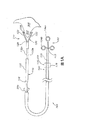
図解の目的のために、しかしこれにより限定されないが、本明細書の態様及び図1(a)に示されるように、医療器具100は、組織のひだ形成器110と共に提供される。図1(a)に示すように、組織のひだ形成器110は、近位端112、遠位端114及び細長い本体116を含む。図1(a)の態様では、組織ひだ形成器は、鉗子120を使用して組織300を機械的に締めつけることにより組織300にひだを形成する。鉗子120は、組織300を機械的に掴んでひだ302を形成するように、ヒンジ126で開閉するのに適合する第一及び第二のあご122を含む。ヒンジ126は、軸のみを有する実ヒンジ又はあごを開閉のどちらかに偏らせる材料のようなスプリングからなる一体のヒンジであり得る。必要であれば、鉗子120は、組織を掴むために多数の歯128を含むことができる。
For illustrative purposes, but not limited thereto, as shown in the aspects herein and in FIG. 1 (a), a
図1(a)で示すように、ひだ形成器アクチュエータ130が提供される。アクチュエータ130は、ひだ形成器110の近位端112に操作可能に連結される。ひだ形成器アクチュエータ130は、組織ひだ形成器が標的領域から外れた(この時、あご122が開いている)第一の位置から、組織ひだ形成器のあご122が標的領域に関する第二の位置に、組織ひだ形成器110を調整するように構成され適合する。ヒンジ126が一体のヒンジである場合、アクチュエータは、ヒンジ126の偏りに対抗するように構成され適合させることができる。つまり、アクチュエータ130は、必要に応じてあご122を広げて離す又は一緒になるように適合させることができる。
As shown in FIG. 1 (a), a fold
アクチュエータは、いろいろな形態を採用することができる。例えば、図1(a)に示すように、アクチュエータ130は、部品134a及び134bを有するハンドル134に連結して操作できる複数の連結器132a及び132bを含む。部品134aは、134bに対して動き、あご122は互いに閉じるか又は開くようにすることができる。ハンドル134は、種々の形態を採用できる。2つの部品のプッシュプル式ハンドル134が示されているが、当該技術分野で公知のその他のアクチュエータも使用することができる。例えば、Lauの米国特許第6,488,694号及びOlsonの米国特許第5,906,619号(それらの明細書は、本明細書に参照して取り込まれる)に記載のような格納式の外筒の装置、と同様なネジ回転式のアクチュエータがある。
Various forms can be adopted for the actuator. For example, as shown in FIG. 1 (a), the
連結器132a、132bは、相対的な動きができる種々の形態を採用することができる。例えば、図1(a)に示すように、連結器132a、132bは、連結器132が広がるのを防ぐように外筒133内に配置することができる。更なる例では、連結器132は、図2に示すように同心円状に形成することができる。ここにおいて、外側の連結器132aは、軸鞘外筒形状であり、あご122が組織を掴むようにあご122を内側の連結器132bに沿って滑らせる遠位端132dを有している。更に、アクチュエータの他のタイプは、水圧式、空気圧式及び電磁石式のアクチュエータを含む。
The
ひだ形成器110は、種々の方法で組織300を掴み、ひだ302を形成することができる。鉗子120で組織を機械的に掴むのに加えて又はその代わりに、図3に示すように組織のひだ形成器は、それに吸引して少なくとも一部の組織のひだを形成することもできる。この態様によれば、吸引外筒140は、近位端142及び遠位端144を有し、そしてそこを通る管腔146を規定して提供される。管腔146の近位端142は、吸引源150と流体連絡できるよう設置することができる。吸引源150を駆動させる場合、組織ひだ形成器110は、吸引源150からの吸引で組織300を管腔内に引っ張り少なくとも一部の組織のひだを形成することができる。必要ならば、鉗子120又は同様な構造物を、吸引され管腔に引っ張られた組織を掴むように管腔146内に配置することができる。鉗子120は、医療器具100を患者に導入する場合、最初折り畳んだ状態で提供することができ、そしてその後半径方向に外筒140が広げる。これにより、組織300のより大きなひだ302の形成が容易になる。
The pleat former 110 can grasp the
組織ひだ形成器110は、種々の材料から作製される。組織ひだ形成器110は、心臓に到達するために患者の管腔系を通過するのに十分な柔軟性を有する材料から作製されるべきである。適した材料には、例えば、手術用グレードのステンレススチール、ニチノール、その他のアロイ、プラスチック、高分子物質等が含まれる。鉗子120の少なくとも第一及び第二のあご122を、例えば、白金、金、バリウム又はイリジウムのような透視装置下で可視の放射線不透過性材料から作製することも可能である。鉗子120は、高価でない手術用鉄で作製でき、そして放射線不透過性材料でメッキすることもできる。同様に、放射線不透過性の材料から作製されるマーカーバンド121は、図1(a)に示すように提供することもできる。更なる例によれば、微粒子を含む材料、表面の質感を変えた材料、超微粒気泡を含む材料等のような、超音波診断下で可視の材料を使用することができる。更に、磁気共鳴映像法を用いる場合、医療器具100は、カーボン繊維等を含む複合材料のような、高磁場で感度が悪い材料から作製することができる。
The tissue fold former 110 is made from a variety of materials. The
更に本発明によれば、本発明の医療器具は、医療器具を患者から外した後に、ひだを保持するようにひだに把持器を適用する把持器適用器を含む。 Further in accordance with the present invention, the medical device of the present invention includes a gripper applicator that applies the gripper to the fold to hold the fold after the medical device is removed from the patient.
図解の目的ために、しかしこれにより限定されないが、本明細書の態様及び図1(a)に示すように、医療器具100は、把持器適用器160を含む。把持器適用器160は、好ましくは、組織ひだ形成器110と関連して操作されるが、必要ならば、別々に導入することができる。把持器適用器160は、医療器具100を患者から外した後に、ひだ302を保持するように、以下に詳しく述べるが、ひだ302に把持器200を適用するのに適合して構成されている。
For illustrative purposes, but not limited thereto, as shown in the aspects herein and in FIG. 1 (a), the
把持器適用器160は、把持器200を組織ひだ形成器110に沿って標的部位に送達するように適合して構成される。この態様によれば、把持器適用器160は、モノレール式で組織ひだ形成器110の外側115に沿って標的部位に送達するように適合して構成される。或いは、図1(a)〜1(e)に示すように、組織ひだ形成器110は、そこを通る管腔118を規定することができ、把持器適用器160は、組織ひだ形成器110によって規定される管腔118を通って把持器を標的部位Tに送達するように適合して構成できる。
The
図1(a)及び図4に示すように、把持器適用器160は、把持器適用器160に連結して操作できる適用器アクチュエータ170を含み、ここにおいて、アクチュエータは、組織300のひだ302上に把持器200を取り付けるように構成され適合している。図4に示すように、適用器アクチュエータ170は、把持器を標的部位Tに前進させるための前進機構172を含む。ハンドル176は、前進機構172を操作するために備えられる。
As shown in FIGS. 1 (a) and 4, the
図1(a)に示すように、前進機構172は、組織ひだ形成器の外側115に沿うか又は図1(b)に示すようにひだ形成器110の管腔118を通って、把持器200を前進させる押し出しチューブの形態で提供することができる。前進機構172は、本明細書で開示の他の態様の中で、ひだ形成器110の外側115に沿って把持器200を前進させるように、図5に示すようにプランジャー179によって作動させられる水圧ピストンとしても提供される。前進機構172は、標的領域近辺に把持器を位置するためのプッシュプル装置と、把持器200でカットして組織を損なうことなくひだの上に把持器を正確にセットするネジ式微調整との組み合わせであってもよい。
As shown in FIG. 1 (a), the
必要であれば、把持器200を組織のひだ302とかみ合わせるかみ合わせ機構174も備えることができる。ハンドル178は、かみ合わせ機構174を作動させるために備えられる。かみ合わせ機構174は、いろいろな形態を採用することもできる。例えば、図4に示すように、かみ合わせ機構174は、ひだ302にかみ合わせる把持器200を締めつける複数のあご175を含むことができる。あご175は、把持器200を押し付けてひだ302に固定するように、前進機構に対して、例えば管177をあご175の上に前進することにより作動させることができる。更なる例では、図7(e)に示すように、かみ合わせ機構174は、医療器具100によって規定される縦軸Xで回転し、らせん状経路で把持器200を動かして把持器200とひだ302の間のかみ合わせに作用するように構成することができる。かみ合わせ機構は、ネジ結合、圧力嵌め込み、又は図7(e)に示すようにかみ合わせ機構174の外周にある穴174aにらせん部材200の端200aが嵌め込まれている、のような種々の方法で、らせん部材200をかみ合わせるように構成された軸Xで回転する管の形態で提供される。
If desired, a
本明細書に記載のシステムは、好ましくは、把持器200を組み合わせた医療器具100の患者の標的部位Tへの送達を容易にするアウターカテーテル(ガイドカテーテルのような)を含む。図解するだけのために図6で示すように、アウターカテーテル190は、近位端192及び遠位端194を含み、そしてそこを通る管腔196を規定する。医療器具100は、アウターカテーテル190の管腔196内に配置されて、システムのインナーカテーテルとして作動する。
The system described herein preferably includes an outer catheter (such as a guide catheter) that facilitates delivery of the
アウターカテーテル190は、Samuelsonの米国特許第6,464,683号又はFontirrocheの米国特許第5,538,510号(それらの明細書は、本明細書に参照して取り込まれる)に記載のような多層の高分子押出物を含む種々の材料から作製することができる。金属の編み材料のような編み込みで強化された単層又は多層の管を含む、その他の構造も可能である。
The
図6に示すように、アウターカテーテル190は、第一の管腔196に平行な第二の管腔198を更に規定することができる。第二の管腔198は、有益な薬剤222の供給源220に結合することができ、そしてシステムは、第二の管腔198を経て、例えばプランジャー224を作動させて有益な薬剤222を標的部位Tに選択的に送達するのに適合して構成することができる。有益な薬剤は、造影剤、薬物、ウイルスベクター及び遺伝物質よりなる群から選ぶことができる。高分子物質、高分子マトリックス中の細胞、ナノ粒子等を含む、その他の有益な薬剤もこの方法で送達することができる。
As shown in FIG. 6, the
更に又は或いは、補強ワイヤー230は、アウターカテーテル190に望ましい剛性の特性を与えるために第二の管腔198内に配置することができる。補強ワイヤー230は、必要ならば、第二の管腔内に移動可能に、又は固定して配置することができる。補強ワイヤーは、近位部分232、中間部分234及び遠位部分236を有して提供される。補強ワイヤー230は、その長さに沿って変化する剛性を有することができる。例えば、アウターカテーテル190に堅さを提供する比較的堅い近位部分232を有し、中間及び遠位部分234、236は徐々により低い剛性である補強ワイヤーが望ましい。適用状況によるが、近位部分232より堅い中間部分234又は遠位部分236を有する補強ワイヤーの使用がより有益になるかもしれない。補強ワイヤー230は、ステンレススチール、ニチノール、種々の適当なプラスチック及びその他のアロイを含む種々の材料から作製することができる。補強ワイヤー230は、以下に述べるように管腔198内に動き易いように滑らかなコーティングで被覆することもできる。
Additionally or alternatively, the reinforcing
本明細書に記載のシステム(例えば、医療器具100、アウターカテーテル190)又は部品の種々の構成材の何れの表面も、摩擦力の低減により処置がし易いように1つ又はそれ以上の適当な潤滑コーティングを実施することができる。このようなコーティングは、例えば、ポリテトラフルオロエチレン(PTFE)又はシリコンオイルのような疎水性物質、又はポリビニルピロリドン(PVP)のような親水性のコーティング剤を含むことができる。例えば、音波発生物質、放射線不透過性物質及びヒドロゲルを含む、その他のコーティング剤も可能である。
Any surface of the various components of the system (eg,
別の態様では、本明細書に開示のように、本発明のシステムは、組織のひだを保持する把持器を含むこともできる。 In another aspect, as disclosed herein, the system of the present invention can also include a grasper for holding a tissue fold.
図解の目的のために、しかしこれにより限定されないが、図7(a)に示すように、把持器200が提供される。把持器200は、近位端204、遠位端206及び本体205を有する近位部分202を含み、ここにおいて、本体部分の近位端204は、適用器160と接合する接合部分208を規定できる。把持器200は、患者の血管系の組織を経て通過するのに適合して構成される第一の突起212を含む遠位部分210を更に備えて提供することができる。把持器は、本体部分202に結合する第二の突起214を含むことができる。第二の突起214は、第一の突起と第二の突起の間の組織のひだを捉えるための開状態から、図7(b)に示すように適用器によって組織のひだを保持するための閉状態に変形することができる。把持器200の接合部分208は、図7(a)に示すような適用器の部分を受けるのに適合して構成されるループを規定することができる。
For illustration purposes, but not limited thereto, as shown in FIG. 7 (a), a
把持器200は、種々の形態を採用することができる。例えば、ループ208は除かれて、適用器が突起212及び214と接合するように構成され適合することができる。ループ208は、本体205を除くことにより突起212、214に直接結合することもできる。更に、把持器200は、本体部分200に結合する第三の突起216のような追加の突起を有することができ、ここにおいて、第二の突起214及び第三の突起216は、開状態では本体部分202と一般に平行である。
The
更なる例によれば、図7(c)に示すように、把持器200は、実質的リング形状である。必要であれば、把持器は、図4で示すように、組織のひだ302についての適用器160のあご175によってヒンジ部分201で折り畳むのに適合して構成することができる。更なる例では、図7dで示すように、把持器200は、らせん形状であってもよく、把持器を標的部位に導入する医療器具により規定される縦軸に回転できる。把持器は、把持器が組織300から後退するのを防ぐ1つ又はそれ以上の逆とげ203、更に必要であれば後で移動できるような1つ又はそれ以上のツメ213を備えることができる。
According to a further example, as shown in FIG. 7 (c), the
把持器200は、例えば形状記憶物質、放射線不透過性物質、再吸収可能な物質、高分子物質、音波発生物質及び/又は蛍光透視可能な物質を含む種々の物質から作製することができる。形状記憶物質から作製される場合、把持器は、体温に到達するとひだ302を締めつけるように構成することができる。例えば、図7dに示されるような把持器は、形状記憶物質から作製され、図7(e)に示すような引き伸ばしたとげが、温度が上昇すると図7dで示すように縦方向にリング形状へと押し込むように設定することができる。
The
本明細書のシステムのその他の変化も可能である。例えば、何れかの望ましい数のあご122を含む組織ひだ形成器を、使用することができる。例えば、図8(a)に示すように2本以上のあご122を用いることが可能である。図8(a)の態様では、4本のあご122が鉗子120を作るために用いられる。下方のあご122a及び122bが、上方のあご122c及び122dと相対的に動くことができる。更にあご122a及び122bは、あご122c及び122dのそれぞれに対して横方向に動くことができ、把持器200の送達を容易にする。
Other variations of the system herein are possible. For example, a tissue fold former including any desired number of
図8(a)の態様では、把持器200は、最初2つの別の部品として提供される。第一の部品207は、下方のあご122a及び122bの間に留め、第二の部品209は上方のあご122c及び122dの間に留められている。ひだ形成器110は、図8(b)に示すように標的部位Tに前進させ、次いであご122のセットをひだを形成するように一緒に持って行く。このように、第一の部品207と第二の部品209は、接合する。ひだ302が有益な結果(僧帽弁の逆流を低減するような)を生むならば、下方のあご122a及び122bが互いに離れ、上方のあご122c及び122dも互いに離れて、把持器を解放し、ひだ302を保持する。あご112(a〜d)を望ましく動かす機械的なアクチュエータ(示していない)は、望ましい動きを生み出すように設計することができる。
In the embodiment of FIG. 8 (a), the
本発明の別な態様によれば、患者の管腔系を治療するための方法が、提供される。 According to another aspect of the present invention, a method for treating a patient's luminal system is provided.
図解のために、しかしこれにより限定されないが、本明細書の態様のように、方法は、ひだ形成器110の遠位部分112のような組織にひだを生成するための遠位部分を有する、医療器具100のような、インナーカテーテルを提供する工程を含む。
For purposes of illustration, but not limited thereto, as in the aspects herein, the method has a distal portion for generating folds in tissue, such as the
方法は、インナーカテーテルを患者の管腔系に導入して、遠位部分をひだを作るべき標的部位に前進させることを更に含む。一態様による例によれば、方法は、好ましくは、患者の管腔系に、例えば大腿動脈を経てアクセスすることで始まる。トロカール(示していない)のような弁付きアダプターを血液の損失を避けるために開口部に据える。次に、ガイドワイヤー250をトロカールを通じて導入して、患者の標的部位Tに前進させる。標的部位は、患者の僧帽弁310であり得るが、必要であれば、患者の管腔系の他の場所であってもよい。僧帽弁310は、必要ならば、心房側又は心室側から接近することができる。
The method further includes introducing an inner catheter into the patient's luminal system to advance the distal portion to the target site to be pleated. According to an example according to one aspect, the method preferably begins with accessing the patient's luminal system, eg, via the femoral artery. A valved adapter such as a trocar (not shown) is placed in the opening to avoid blood loss. Next, the
好ましくは、図9及び図1(b)〜1(e)に示すように、アウターカテーテル190が、次にガイドワイヤーを越えて患者の管腔系に導入される。アウターカテーテル190の遠位末端194は、患者の標的部位Tの近辺、例えば僧帽弁310の近辺に位置付けられる。手法は、好ましくは標的部位が見える状態下で、例えば、蛍光透視、超音波又は磁気共鳴診断の下で実施される。
Preferably, as shown in FIG. 9 and FIGS. 1 (b) -1 (e), the
次に、ガイドワイヤー250が回収されて、医療器具100が患者の管腔系に、図1(b)〜1(e)に示すようにアウターカテーテル190の管腔196を経て導入される。ひだ形成器110の遠位末端112は、あご122が標的部位Tの近辺に位置するまで、アウターカテーテルの管腔196を通って遠くに移動する。あご122は、その後ひだ形成器アクチュエータ130を用いて動かされて、開状態となる。あごは、備えられているならば歯128で組織300を掴むように、更に標的部位Tの組織300に向けて前進させる。アクチュエータ130は、図1(c)に示すように、ひだ302を形成するようにあご122を組織300に接近させ、引っ張るように操作される。
Next, the
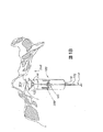
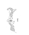
組織のひだ302は、好ましくは、図10(a)〜10(b)に示すように、僧帽弁の後尖304近辺の、僧帽弁輪の外側円周方向に沿った組織をつまむことにより形成される。ひだ302は、弁輪近辺の繊維組織で形成され得るが、好ましくは、心室314の壁312又は心房318の壁316の筋肉組織で形成される。ひだ302を形成する目的は、それをつまむことにより僧帽弁の周辺域320を効率的に減少させることである。成功すると、僧帽弁の後尖304及び前尖306の端304a及び306aを理想的には再調整させて、これにより僧帽弁の逆流を減少させることになる。図10(a)で見られるように、僧帽弁の周辺域319は、処置後に、図10(b)と比べてみると、減少している。
The tissue pleats 302 preferably pinch tissue along the outer circumferential direction of the mitral annulus near the
一旦ひだ302が形成されると、必要により、ひだ302の形成がもたらした、弁尖304及び306の調整の効果をみることが可能である。僧帽弁310の逆流は、ひだ形成が有益な結果となるのか否かを判断するために、処置時に蛍光透視下で観察することができる。もし結果が有益でなければ、ひだ302は組織を恒久的に変化させずに解放することができる。僧帽弁の逆流を下げるように、次に異なる位置で新しいひだを形成することができる。以上のように、仮のひだを形成する手法は、通常心臓を停止する必要のあるより侵襲性の手術に比べて大きな利点を提供する。しかしながら、もし結果がある程度逆流を減少させるならば、ひだ302は、把持器200をひだに適用して保持される。把持器200は、本明細書に記載のような何れかの方法で送達することができる。
Once the
ある特定の状況下では、最初に仮のひだを形成することなく、把持器200を使用して単一工程でひだを形成することも可能である。この態様によれば、医療器具100は、患者の僧帽弁近辺の心臓内の筋肉組織に組織のひだを形成するのに適合して構成される組織ひだ形成器110を有して提供される。組織ひだ形成器は、把持器200を送達する前に組織のひだ302を形成することなく、把持器200を標的部位Tに単一工程で送達することもできる。
Under certain circumstances, it is also possible to form the pleats in a single step using the
僧帽弁310近辺に、互いに半径方向に位置した追加のひだ302を、必要であれば形成することができる。このようなひだ302は、僧帽弁310の周辺域を更に減少させるために、追加の把持器200によってその場所で保持される。
本発明の方法及びシステムは、上記のようにそして図に示されるように、例えば使用の容易さ及び効率の良さを含む優れた特性を有する、僧帽弁の逆流を治療するための医療器具及び方法を提供するものである。当業者であれば、多種の修飾及び変更が、本発明の精神及び範囲から逸脱することなく、本発明の器具及び方法になされることは、明らかであろう。従って、本発明は、添付の特許請求の範囲及びそれらの均等物の範囲内である修飾及び変更を含むことを意図されている。 The method and system of the present invention provides a medical device for treating mitral valve regurgitation, as described above and shown in the figures, having superior properties including, for example, ease of use and efficiency. A method is provided. It will be apparent to those skilled in the art that various modifications and variations can be made to the apparatus and method of the present invention without departing from the spirit and scope of the invention. Thus, it is intended that the present invention include modifications and variations that are within the scope of the appended claims and their equivalents.
Claims (56)
(b)組織ひだ形成器と連携して操作される把持適用器(この把持適用器は、医療器具が患者から外された後に、ひだを保持するように把持器をひだに適用するのに適合して構成される)、
を含んでなる、医療器具。 (A) a tissue fold former adapted to form tissue folds near a patient's target site;
(B) a grasping applicator operated in conjunction with a tissue plication device (this grasping applicator is adapted to apply the grasper to the pleat so as to hold the pleat after the medical device is removed from the patient) Configured)
Comprising a medical device.
把持適用器が、把持器を組織ひだ形成器で規定される管腔に沿って標的部位に送達するように適合して構成される、
請求項9に記載の医療器具。 A tissue plication device defines a lumen through which the tissue plication device is configured, and a grasping applicator is adapted and configured to deliver the grasper to the target site along the lumen defined by the tissue plication device ,
The medical device according to claim 9.
を更に含んでなる、請求項14に記載の医療器具。 A grasping applicator that is operated in conjunction with the tissue plication device and is adapted to apply the grasper to the pleat to hold the pleat after removing the medical device from the patient;
The medical device according to claim 14, further comprising:
を含んでなる医療器具。 A grasping applicator adapted to apply the grasper to the tissue fold by rotating the grasper about a longitudinal axis defined by the grasping applicator holding the fold after removing the medical device from the patient ,
A medical device comprising:
ii)医療器具を患者から外した後に、ひだを保持するために把持器をひだに適用するように構成され適合する把持適用器、を含むインナーカテーテル、及び
b)医療器具を患者から外した後に、組織のひだを保持するように構成され適合する把持器、
を含んでなるシステム。 a) i) a tissue fold former adapted to form tissue folds near the target site of the patient;
ii) an inner catheter that includes a grasping applicator configured and adapted to apply a grasper to the pleat to hold the pleat after the medical device is removed from the patient; and b) after the medical device is removed from the patient. A grasper configured and adapted to hold tissue folds,
System comprising.
a)本体部分の近位端が適用器と接合するための接合部分を規定し、そして遠位端が患者の血管系の組織を経て通過するのに適合して構成される第一の突起を含む、近位端及び遠位端を有する本体部分、及び
b)第一の突起と第二の突起の間の組織のひだを捉えるための開状態から、適用器で組織のひだを保持するための閉状態に変形可能である、本体部分に結合する第二の突起、
を含む、請求項17に記載のシステム。 The gripper is
a) a first protrusion configured to be adapted to pass through the tissue of the patient's vasculature with the proximal end of the body portion defining a joint portion for joining with the applicator; A body portion having a proximal end and a distal end, and b) to hold a tissue fold with an applicator from an open state to capture the tissue fold between the first and second projections A second protrusion coupled to the body portion, which is deformable to a closed state of
The system of claim 17, comprising:
(b)患者の管腔系にインナーカテーテルを導入して、ひだを作る標的部位に遠位部分を前進させること、
(c)標的部位近辺の組織を仮にひだ形成して、第一のひだを形成すること、
(d)第一の把持器を第一のひだに適用すること、そして
(e)患者からインナーカテーテルを移動させること、
を含んでなる方法。 (A) providing an inner catheter having a distal portion for generating folds in tissue;
(B) introducing an inner catheter into the patient's luminal system and advancing the distal portion to the fold target site;
(C) temporarily pleats tissue near the target site to form a first fold;
(D) applying a first grasper to the first fold; and (e) moving the inner catheter from the patient;
Comprising a method.
(b)第二及び第三の把持器を第二及び第三のひだに適用して、僧帽弁の周辺域を更に減少させること、
の工程を更に含んでなる、請求項46に記載の方法。 (A) in the vicinity of the mitral valve, the first pleat is moved radially to form second and third pleats; and (b) the second and third graspers are second and third. To further reduce the area around the mitral valve,
47. The method of claim 46, further comprising:
(b)患者の管腔系にインナーカテーテルを導入して、心臓内の部位近辺に遠位部分を前進させること、
(c)心臓内組織をつかみ、そこでひだを形成すること、
を含んでなる方法。 (A) providing an inner catheter having a distal portion for generating folds in tissue;
(B) introducing an inner catheter into the patient's luminal system to advance the distal portion near the site within the heart;
(C) grab the tissue in the heart and form folds there;
Comprising a method.
(b)患者の管腔系にインナーカテーテルを導入して、管腔系の内側面近辺に遠位部分を前進させること、
(c)心臓内の組織をつかみ、そこでひだを形成すること、そして
(d)インナーカテーテルにより規定される縦軸に把持器を回転させて、ひだを保持するように把持器を付着させること、
を含んでなる方法。 (A) providing an inner catheter having a distal portion for generating folds in tissue;
(B) introducing an inner catheter into the patient's luminal system and advancing the distal portion near the inner surface of the luminal system;
(C) grasping tissue in the heart and forming pleats there; and (d) rotating the grasper about the longitudinal axis defined by the inner catheter to attach the grasper to hold the folds;
Comprising a method.
Applications Claiming Priority (2)
| Application Number | Priority Date | Filing Date | Title |
|---|---|---|---|
| US73041005P | 2005-10-26 | 2005-10-26 | |
| PCT/US2006/041369 WO2007050546A2 (en) | 2005-10-26 | 2006-10-24 | Devices and methods for treating mitral valve regurgitation |
Publications (2)
| Publication Number | Publication Date |
|---|---|
| JP2009513255A true JP2009513255A (en) | 2009-04-02 |
| JP2009513255A5 JP2009513255A5 (en) | 2009-12-10 |
Family
ID=37968446
Family Applications (1)
| Application Number | Title | Priority Date | Filing Date |
|---|---|---|---|
| JP2008537854A Pending JP2009513255A (en) | 2005-10-26 | 2006-10-24 | Apparatus and method for treating mitral regurgitation |
Country Status (6)
| Country | Link |
|---|---|
| US (1) | US20070093857A1 (en) |
| EP (1) | EP1945110A2 (en) |
| JP (1) | JP2009513255A (en) |
| AU (1) | AU2006306391A1 (en) |
| CA (1) | CA2626540A1 (en) |
| WO (1) | WO2007050546A2 (en) |
Cited By (1)
| Publication number | Priority date | Publication date | Assignee | Title |
|---|---|---|---|---|
| JP2016526448A (en) * | 2013-07-10 | 2016-09-05 | ボストン サイエンティフィック サイムド,インコーポレイテッドBoston Scientific Scimed,Inc. | Tissue grasping and wound closure clip device |
Families Citing this family (68)
| Publication number | Priority date | Publication date | Assignee | Title |
|---|---|---|---|---|
| US6682473B1 (en) | 2000-04-14 | 2004-01-27 | Solace Therapeutics, Inc. | Devices and methods for attenuation of pressure waves in the body |
| US10327880B2 (en) | 2000-04-14 | 2019-06-25 | Attenuex Technologies, Inc. | Attenuation device for use in an anatomical structure |
| US6764510B2 (en) | 2002-01-09 | 2004-07-20 | Myocor, Inc. | Devices and methods for heart valve treatment |
| WO2007038476A2 (en) | 2005-09-26 | 2007-04-05 | Atteneux Technologies, Inc. | Pressure attenuation device |
| GB2437921B (en) * | 2006-05-10 | 2011-08-03 | Francis Wells | Heart valve repair |
| WO2008090978A1 (en) * | 2007-01-26 | 2008-07-31 | Olympus Medical Systems Corp. | Holding device and holding tool |
| US8197464B2 (en) | 2007-10-19 | 2012-06-12 | Cordis Corporation | Deflecting guide catheter for use in a minimally invasive medical procedure for the treatment of mitral valve regurgitation |
| US8226709B2 (en) * | 2007-10-19 | 2012-07-24 | Cordis Corporation | Method and system for plicating tissue in a minimally invasive medical procedure for the treatment of mitral valve regurgitation |
| US8652202B2 (en) | 2008-08-22 | 2014-02-18 | Edwards Lifesciences Corporation | Prosthetic heart valve and delivery apparatus |
| US20100094334A1 (en) * | 2008-10-10 | 2010-04-15 | Matthew Krever | Plication device with formable linear fastener for use in the direct plication annuloplasty treatment of mitral valve regurgitation |
| EP2367503A1 (en) * | 2008-11-25 | 2011-09-28 | AttenueX Technologies, Inc. | Implant with high vapor pressure medium |
| US8449599B2 (en) | 2009-12-04 | 2013-05-28 | Edwards Lifesciences Corporation | Prosthetic valve for replacing mitral valve |
| EP2670313B1 (en) | 2011-02-01 | 2016-01-20 | St. Jude Medical, Inc. | Apparatus for heart valve repair |
| WO2012177441A1 (en) * | 2011-06-21 | 2012-12-27 | St. Jude Medical, Inc. | Apparatus and method for heart valve repair |
| WO2013112795A1 (en) | 2012-01-25 | 2013-08-01 | St. Jude Medical, Inc. | Apparatus and method for heart valve repair |
| US9883855B2 (en) | 2012-01-25 | 2018-02-06 | St. Jude Medical, Llc | Apparatus and method for heart valve repair |
| WO2013116617A1 (en) | 2012-02-02 | 2013-08-08 | St. Jude Medical, Cardiology Division, Inc. | Apparatus and method for heart valve repair |
| WO2013123059A1 (en) | 2012-02-13 | 2013-08-22 | Mitraspan, Inc | Method and apparatus for repairing a mitral valve |
| US10076414B2 (en) | 2012-02-13 | 2018-09-18 | Mitraspan, Inc. | Method and apparatus for repairing a mitral valve |
| US9662205B2 (en) | 2012-08-02 | 2017-05-30 | St. Jude Medical, Cardiology Division, Inc. | Apparatus and method for heart valve repair |
| US10105219B2 (en) | 2012-08-02 | 2018-10-23 | St. Jude Medical, Cardiology Division, Inc. | Mitral valve leaflet clip |
| US8894563B2 (en) | 2012-08-10 | 2014-11-25 | Attenuex Technologies, Inc. | Methods and systems for performing a medical procedure |
| US9642706B2 (en) | 2013-03-11 | 2017-05-09 | St. Jude Medical, Llc | Apparatus and method for heart valve repair |
| US9999425B2 (en) * | 2013-03-13 | 2018-06-19 | St. Jude Medical, Cardiology Division, Inc. | Mitral valve leaflet clip |
| EP2945557B1 (en) | 2013-03-15 | 2017-01-11 | Gyrus Acmi, Inc. | Combination electrosurgical device |
| US10085793B2 (en) | 2013-03-15 | 2018-10-02 | Gyrus Acmi, Inc. | Offset forceps |
| EP2967719B1 (en) | 2013-03-15 | 2017-07-12 | Gyrus Acmi Inc. | Electrosurgical instrument |
| US20140276797A1 (en) | 2013-03-15 | 2014-09-18 | GYRUS ACMI, INC., d/b/a Olympus Surgical Technologies America | Combination electrosurgical device |
| EP2974682B1 (en) | 2013-03-15 | 2017-08-30 | Gyrus ACMI, Inc. | Combination electrosurgical device |
| WO2016004046A1 (en) * | 2014-07-01 | 2016-01-07 | Boston Scientific Scimed, Inc. | Hemostatic clip with needle passer |
| WO2016028882A1 (en) | 2014-08-20 | 2016-02-25 | GYRUS ACMI, INC. (d/b/a OLYMPUS SURGICAL TECHNOLOGIES AMERICA) | Multi-mode combination electrosurgical device |
| CN107205817B (en) | 2014-12-04 | 2020-04-03 | 爱德华兹生命科学公司 | Percutaneous clamp for repairing heart valve |
| EP3738551A1 (en) | 2015-05-14 | 2020-11-18 | Edwards Lifesciences Corporation | Heart valve sealing devices and delivery devices therefor |
| US10799675B2 (en) | 2016-03-21 | 2020-10-13 | Edwards Lifesciences Corporation | Cam controlled multi-direction steerable handles |
| US11219746B2 (en) | 2016-03-21 | 2022-01-11 | Edwards Lifesciences Corporation | Multi-direction steerable handles for steering catheters |
| US10799677B2 (en) | 2016-03-21 | 2020-10-13 | Edwards Lifesciences Corporation | Multi-direction steerable handles for steering catheters |
| US10835714B2 (en) | 2016-03-21 | 2020-11-17 | Edwards Lifesciences Corporation | Multi-direction steerable handles for steering catheters |
| US10973638B2 (en) | 2016-07-07 | 2021-04-13 | Edwards Lifesciences Corporation | Device and method for treating vascular insufficiency |
| US10653862B2 (en) | 2016-11-07 | 2020-05-19 | Edwards Lifesciences Corporation | Apparatus for the introduction and manipulation of multiple telescoping catheters |
| US10905554B2 (en) | 2017-01-05 | 2021-02-02 | Edwards Lifesciences Corporation | Heart valve coaptation device |
| US10213306B2 (en) * | 2017-03-31 | 2019-02-26 | Neochord, Inc. | Minimally invasive heart valve repair in a beating heart |
| RU2759657C2 (en) | 2017-04-18 | 2021-11-16 | Эдвардз Лайфсайенсиз Корпорейшн | Apparatus for sealing a cardiac valve and apparatus for delivery thereof |
| US11224511B2 (en) | 2017-04-18 | 2022-01-18 | Edwards Lifesciences Corporation | Heart valve sealing devices and delivery devices therefor |
| US10799312B2 (en) | 2017-04-28 | 2020-10-13 | Edwards Lifesciences Corporation | Medical device stabilizing apparatus and method of use |
| US10959846B2 (en) | 2017-05-10 | 2021-03-30 | Edwards Lifesciences Corporation | Mitral valve spacer device |
| US11051940B2 (en) | 2017-09-07 | 2021-07-06 | Edwards Lifesciences Corporation | Prosthetic spacer device for heart valve |
| US11065117B2 (en) | 2017-09-08 | 2021-07-20 | Edwards Lifesciences Corporation | Axisymmetric adjustable device for treating mitral regurgitation |
| US11110251B2 (en) | 2017-09-19 | 2021-09-07 | Edwards Lifesciences Corporation | Multi-direction steerable handles for steering catheters |
| US10667834B2 (en) | 2017-11-02 | 2020-06-02 | Gyrus Acmi, Inc. | Bias device for biasing a gripping device with a shuttle on a central body |
| US11383373B2 (en) | 2017-11-02 | 2022-07-12 | Gyms Acmi, Inc. | Bias device for biasing a gripping device by biasing working arms apart |
| US11298801B2 (en) | 2017-11-02 | 2022-04-12 | Gyrus Acmi, Inc. | Bias device for biasing a gripping device including a central body and shuttles on the working arms |
| KR20240005248A (en) | 2018-01-09 | 2024-01-11 | 에드워즈 라이프사이언시스 코포레이션 | Native valve repair devices and systems |
| US10105222B1 (en) | 2018-01-09 | 2018-10-23 | Edwards Lifesciences Corporation | Native valve repair devices and procedures |
| US10507109B2 (en) | 2018-01-09 | 2019-12-17 | Edwards Lifesciences Corporation | Native valve repair devices and procedures |
| US10123873B1 (en) | 2018-01-09 | 2018-11-13 | Edwards Lifesciences Corporation | Native valve repair devices and procedures |
| US10231837B1 (en) | 2018-01-09 | 2019-03-19 | Edwards Lifesciences Corporation | Native valve repair devices and procedures |
| US10238493B1 (en) | 2018-01-09 | 2019-03-26 | Edwards Lifesciences Corporation | Native valve repair devices and procedures |
| US10076415B1 (en) | 2018-01-09 | 2018-09-18 | Edwards Lifesciences Corporation | Native valve repair devices and procedures |
| US10973639B2 (en) | 2018-01-09 | 2021-04-13 | Edwards Lifesciences Corporation | Native valve repair devices and procedures |
| US10245144B1 (en) | 2018-01-09 | 2019-04-02 | Edwards Lifesciences Corporation | Native valve repair devices and procedures |
| US10159570B1 (en) | 2018-01-09 | 2018-12-25 | Edwards Lifesciences Corporation | Native valve repair devices and procedures |
| US10136993B1 (en) | 2018-01-09 | 2018-11-27 | Edwards Lifesciences Corporation | Native valve repair devices and procedures |
| US10111751B1 (en) | 2018-01-09 | 2018-10-30 | Edwards Lifesciences Corporation | Native valve repair devices and procedures |
| US11389297B2 (en) | 2018-04-12 | 2022-07-19 | Edwards Lifesciences Corporation | Mitral valve spacer device |
| US11207181B2 (en) | 2018-04-18 | 2021-12-28 | Edwards Lifesciences Corporation | Heart valve sealing devices and delivery devices therefor |
| US10945844B2 (en) | 2018-10-10 | 2021-03-16 | Edwards Lifesciences Corporation | Heart valve sealing devices and delivery devices therefor |
| US20200254226A1 (en) | 2019-02-07 | 2020-08-13 | Solace Therapeutics, Inc. | Pressure attenuation device |
| WO2020168081A1 (en) | 2019-02-14 | 2020-08-20 | Edwards Lifesciences Corporation | Heart valve sealing devices and delivery devices therefor |
Citations (2)
| Publication number | Priority date | Publication date | Assignee | Title |
|---|---|---|---|---|
| JPH07111974A (en) * | 1993-10-19 | 1995-05-02 | Olympus Optical Co Ltd | Treating device for inside of celom |
| WO2005058239A2 (en) * | 2003-12-12 | 2005-06-30 | Usgi Medical Inc. | Apparatus and methods for forming and securing gastrointestinal tissue folds |
Family Cites Families (18)
| Publication number | Priority date | Publication date | Assignee | Title |
|---|---|---|---|---|
| CA2060067A1 (en) * | 1991-01-28 | 1992-07-29 | Lilip Lau | Stent delivery system |
| US5538510A (en) * | 1994-01-31 | 1996-07-23 | Cordis Corporation | Catheter having coextruded tubing |
| US5894843A (en) * | 1996-02-20 | 1999-04-20 | Cardiothoracic Systems, Inc. | Surgical method for stabilizing the beating heart during coronary artery bypass graft surgery |
| US6165166A (en) * | 1997-04-25 | 2000-12-26 | Schneider (Usa) Inc. | Trilayer, extruded medical tubing and medical devices incorporating such tubing |
| US5906619A (en) * | 1997-07-24 | 1999-05-25 | Medtronic, Inc. | Disposable delivery device for endoluminal prostheses |
| US20020082592A1 (en) * | 1999-03-17 | 2002-06-27 | Banning Lary | Coronary cutting, dilating, tamponading, and perfusing instrument |
| US7744613B2 (en) * | 1999-06-25 | 2010-06-29 | Usgi Medical, Inc. | Apparatus and methods for forming and securing gastrointestinal tissue folds |
| US6780197B2 (en) * | 2000-01-05 | 2004-08-24 | Integrated Vascular Systems, Inc. | Apparatus and methods for delivering a vascular closure device to a body lumen |
| US7296577B2 (en) * | 2000-01-31 | 2007-11-20 | Edwards Lifescience Ag | Transluminal mitral annuloplasty with active anchoring |
| US7727246B2 (en) * | 2000-12-06 | 2010-06-01 | Ethicon Endo-Surgery, Inc. | Methods for endoluminal treatment |
| US6619291B2 (en) * | 2001-04-24 | 2003-09-16 | Edwin J. Hlavka | Method and apparatus for catheter-based annuloplasty |
| US6939318B2 (en) * | 2002-05-03 | 2005-09-06 | Boston Scientific Scimed, Inc. | Method, tool, and system for deploying an implant into the body |
| US20030139819A1 (en) * | 2002-01-18 | 2003-07-24 | Beer Nicholas De | Method and apparatus for closing septal defects |
| US6833003B2 (en) * | 2002-06-24 | 2004-12-21 | Cordis Neurovascular | Expandable stent and delivery system |
| US6773440B2 (en) * | 2002-07-02 | 2004-08-10 | Satiety, Inc. | Method and device for use in tissue approximation and fixation |
| US6932836B2 (en) * | 2002-07-24 | 2005-08-23 | Jatin Amin | Catheter and stent delivery system |
| US6746460B2 (en) * | 2002-08-07 | 2004-06-08 | Satiety, Inc. | Intra-gastric fastening devices |
| US6994712B1 (en) * | 2002-11-12 | 2006-02-07 | Biopsy Sciences, Llc | Bioabsorbable marker having external anchoring means |
-
2006
- 2006-10-24 EP EP06844213A patent/EP1945110A2/en not_active Withdrawn
- 2006-10-24 WO PCT/US2006/041369 patent/WO2007050546A2/en active Application Filing
- 2006-10-24 AU AU2006306391A patent/AU2006306391A1/en not_active Abandoned
- 2006-10-24 CA CA002626540A patent/CA2626540A1/en not_active Abandoned
- 2006-10-24 JP JP2008537854A patent/JP2009513255A/en active Pending
- 2006-10-25 US US11/586,201 patent/US20070093857A1/en not_active Abandoned
Patent Citations (2)
| Publication number | Priority date | Publication date | Assignee | Title |
|---|---|---|---|---|
| JPH07111974A (en) * | 1993-10-19 | 1995-05-02 | Olympus Optical Co Ltd | Treating device for inside of celom |
| WO2005058239A2 (en) * | 2003-12-12 | 2005-06-30 | Usgi Medical Inc. | Apparatus and methods for forming and securing gastrointestinal tissue folds |
Cited By (1)
| Publication number | Priority date | Publication date | Assignee | Title |
|---|---|---|---|---|
| JP2016526448A (en) * | 2013-07-10 | 2016-09-05 | ボストン サイエンティフィック サイムド,インコーポレイテッドBoston Scientific Scimed,Inc. | Tissue grasping and wound closure clip device |
Also Published As
| Publication number | Publication date |
|---|---|
| AU2006306391A1 (en) | 2007-05-03 |
| WO2007050546A2 (en) | 2007-05-03 |
| CA2626540A1 (en) | 2007-05-03 |
| WO2007050546A3 (en) | 2007-10-11 |
| EP1945110A2 (en) | 2008-07-23 |
| US20070093857A1 (en) | 2007-04-26 |
Similar Documents
| Publication | Publication Date | Title |
|---|---|---|
| JP2009513255A (en) | Apparatus and method for treating mitral regurgitation | |
| US11931023B2 (en) | Tissue clip | |
| JP5844406B2 (en) | Heart valve downsizing apparatus and method | |
| US20230329697A1 (en) | Devices and methods for locating and implanting tissue anchors at mitral valve commissure | |
| US11723769B2 (en) | Tissue grasping devices and related methods | |
| US10285687B2 (en) | Suturing devices and methods for suturing an anatomic valve | |
| JP5198431B2 (en) | Annuloplasty device with helical anchor | |
| JP5530455B2 (en) | Device for minimally invasive heart valve treatment | |
| JP4282993B2 (en) | Methods and apparatus for catheter-based annuloplasty (Background of the Invention) 1. Field of the Invention The present invention relates generally to techniques for treating mitral valve dysfunction, such as mitral valve leakage. More specifically, the invention relates to systems and methods for treating leaky mitral valves in a minimally invasive manner. | |
| JP6190273B2 (en) | Joint-enhanced implants, systems, and methods | |
| CN109715078A (en) | Tissue-grasping device and correlation technique | |
| JP2016521633A (en) | Mitral valve spacer and implantation system and method thereof | |
| JP2012515625A (en) | Magnetic docking system and method for long term adjustment of implantable devices | |
| JP2005534419A (en) | Device for atrioventricular valve repair | |
| JP2014523282A (en) | Minimally invasive repair of heart valve leaflets | |
| WO2007089843A2 (en) | Tissue tack | |
| JP2013208489A (en) | Push-in retainer system for use in direct plication annuloplasty treatment of mitral valve regurgitation | |
| JP2022526046A (en) | A device for repairing the atrioventricular heart valve | |
| US20220168014A1 (en) | Systems, apparatuses, and methods for removing a medical implant from cardiac tissue | |
| CN116634949A (en) | Minimally invasive fixation device for fixation of a feltable textile, kit comprising a fixation device, and method for fixation of a feltable textile at a target site of a patient | |
| CN114376766A (en) | Adjustable removable valve clamping device | |
| CN214049225U (en) | Adjustable removable valve clamping device | |
| JP2022540108A (en) | A medical device for introducing an object to an anatomical target location |
Legal Events
| Date | Code | Title | Description |
|---|---|---|---|
| A521 | Request for written amendment filed |
Free format text: JAPANESE INTERMEDIATE CODE: A523 Effective date: 20091023 |
|
| A621 | Written request for application examination |
Free format text: JAPANESE INTERMEDIATE CODE: A621 Effective date: 20091023 |
|
| A977 | Report on retrieval |
Free format text: JAPANESE INTERMEDIATE CODE: A971007 Effective date: 20111130 |
|
| A131 | Notification of reasons for refusal |
Free format text: JAPANESE INTERMEDIATE CODE: A131 Effective date: 20111206 |
|
| A601 | Written request for extension of time |
Free format text: JAPANESE INTERMEDIATE CODE: A601 Effective date: 20120222 |
|
| A602 | Written permission of extension of time |
Free format text: JAPANESE INTERMEDIATE CODE: A602 Effective date: 20120229 |
|
| A02 | Decision of refusal |
Free format text: JAPANESE INTERMEDIATE CODE: A02 Effective date: 20120731 |