JP2009512828A - Pipes and fittings for pipes - Google Patents
Pipes and fittings for pipes Download PDFInfo
- Publication number
- JP2009512828A JP2009512828A JP2008536857A JP2008536857A JP2009512828A JP 2009512828 A JP2009512828 A JP 2009512828A JP 2008536857 A JP2008536857 A JP 2008536857A JP 2008536857 A JP2008536857 A JP 2008536857A JP 2009512828 A JP2009512828 A JP 2009512828A
- Authority
- JP
- Japan
- Prior art keywords
- tool
- gripping device
- joint
- nut
- band
- Prior art date
- Legal status (The legal status is an assumption and is not a legal conclusion. Google has not performed a legal analysis and makes no representation as to the accuracy of the status listed.)
- Pending
Links
Images


Classifications
-
- F—MECHANICAL ENGINEERING; LIGHTING; HEATING; WEAPONS; BLASTING
- F16—ENGINEERING ELEMENTS AND UNITS; GENERAL MEASURES FOR PRODUCING AND MAINTAINING EFFECTIVE FUNCTIONING OF MACHINES OR INSTALLATIONS; THERMAL INSULATION IN GENERAL
- F16L—PIPES; JOINTS OR FITTINGS FOR PIPES; SUPPORTS FOR PIPES, CABLES OR PROTECTIVE TUBING; MEANS FOR THERMAL INSULATION IN GENERAL
- F16L19/00—Joints in which sealing surfaces are pressed together by means of a member, e.g. a swivel nut, screwed on or into one of the joint parts
- F16L19/08—Joints in which sealing surfaces are pressed together by means of a member, e.g. a swivel nut, screwed on or into one of the joint parts with metal rings which bite into the wall of the pipe
- F16L19/10—Joints in which sealing surfaces are pressed together by means of a member, e.g. a swivel nut, screwed on or into one of the joint parts with metal rings which bite into the wall of the pipe the profile of the ring being altered
- F16L19/103—Joints in which sealing surfaces are pressed together by means of a member, e.g. a swivel nut, screwed on or into one of the joint parts with metal rings which bite into the wall of the pipe the profile of the ring being altered with more than one ring per pipe end being used
-
- F—MECHANICAL ENGINEERING; LIGHTING; HEATING; WEAPONS; BLASTING
- F16—ENGINEERING ELEMENTS AND UNITS; GENERAL MEASURES FOR PRODUCING AND MAINTAINING EFFECTIVE FUNCTIONING OF MACHINES OR INSTALLATIONS; THERMAL INSULATION IN GENERAL
- F16L—PIPES; JOINTS OR FITTINGS FOR PIPES; SUPPORTS FOR PIPES, CABLES OR PROTECTIVE TUBING; MEANS FOR THERMAL INSULATION IN GENERAL
- F16L19/00—Joints in which sealing surfaces are pressed together by means of a member, e.g. a swivel nut, screwed on or into one of the joint parts
- F16L19/06—Joints in which sealing surfaces are pressed together by means of a member, e.g. a swivel nut, screwed on or into one of the joint parts in which radial clamping is obtained by wedging action on non-deformed pipe ends
- F16L19/061—Joints in which sealing surfaces are pressed together by means of a member, e.g. a swivel nut, screwed on or into one of the joint parts in which radial clamping is obtained by wedging action on non-deformed pipe ends a pressure ring being arranged between the clamping ring and the threaded member or the connecting member
Abstract
Description
(関連出願)
本出願は、2005年10月20日に出願され、FITTING FOR TUBE AND PIPE WITH CARTRIDGEと題された、米国特許出願公開第2006/0138774号(出願番号第11/255,499号)の優先権を主張し、この米国特許出願の開示の全体は、参照により本明細書に援用される。本出願はまた、2006年3月14日に出願され、TOOL FOR PREPARING FITTING AND CONDUIT CONNECTIONと題された、米国特許出願第11/375,843号の優先権をも主張し、この米国特許出願の開示の全体は、参照により本明細書に援用される。
(Related application)
This application is filed on Oct. 20, 2005 and has the priority of US Patent Application Publication No. 2006/0138774 (Filing No. 11 / 255,499), entitled FITTING FOR TUBE AND PIPE WITH CARTRIDGE. And the entire disclosure of this US patent application is incorporated herein by reference. This application also claims the priority of US patent application Ser. No. 11 / 375,843, filed Mar. 14, 2006 and entitled TOOL FOR PREPARING FITTING AND CONDUIT CONNECTION. The entire disclosure is incorporated herein by reference.
(発明の背景)
導管、例えば管およびパイプには、数十年間フレアレス継手が使用されてきた。フレアレス継手は、2つの管端またはパイプ端を接続または接合するか、あるいは1つの導管端を別のアセンブリ、例えばタンク、弁、マニホルド等に接続するのに使用される。その応用例は、継手が使用されるアセンブリの種類の分だけ多様である。フレアレス継手の、非常に一般的な1つの種類として、帯金型の継手がある。帯金型の継手では、1つ以上の帯金を使用して、通常継手本体と呼ばれる継手部材に導管端が接合または接続される。その後、継手本体は、別のアセンブリに接合する(またはその一部とする)ことができる。帯金型の継手において、この1つ以上の帯金は、特に加圧下で流体密封止(fluid tight seal)、ならびに導管の適正な把持、および振動疲労からの保護を確立しなければならない。Swagelok社(Solon、Ohio)から利用可能であるような高性能の継手は、密閉が危うくなるか、または帯金が導管上でそれらの把持を喪失し得る前に導管が破裂する時点まで、漏出、振動疲労、および導管破裂なしに継手の定格圧力の何倍もの圧力に耐えることができる。
(Background of the Invention)
Flareless fittings have been used for several decades on conduits such as tubes and pipes. Flareless joints are used to connect or join two pipe ends or pipe ends, or to connect one conduit end to another assembly, such as a tank, valve, manifold, or the like. The applications vary as much as the type of assembly in which the joint is used. One very common type of flareless joint is a band-shaped joint. In a band-type coupling, one or more bands are used to join or connect the conduit ends to a coupling member, commonly referred to as a coupling body. The joint body can then be joined to (or part of) another assembly. In band mold joints, the one or more bands must establish a fluid tight seal, particularly under pressure, as well as proper gripping of the conduit and protection from vibration fatigue. High performance fittings, such as those available from Swagelok (Solon, Ohio), leak to the point where the conduits rupture before the seals are compromised or the straps can lose their grip on the conduits Can withstand many times the rated pressure of the joint without vibration fatigue and conduit rupture.
帯金式の継手は、スクエアリングおよびばり取りが低価格であるという以外に、管端またはパイプ端のいかなる特別な準備も当てにしないという点で、他の端部接続具に勝る利点を有する。これは、帯金が密閉および管把持を行うという理由からである。 Banded fittings have the advantage over other end fittings in that they do not rely on any special provision at the end of the pipe or pipe, other than the low cost of squaring and deburring . This is because the band performs sealing and tube gripping.
帯金を使用するフレアレス継手は、その信頼性が高いため、一般に高機能な化学処理装置において使用される。例えば半導体産業において、このような継手は、高価な、または有毒な化学物質の閉じ込めを確実にする。通常、これらの用途は純度が高いので、ステンレス鋼製、またはその他の低腐食性かつ高強度の合金製の導管に依存している。 Since the flareless joint using a band has high reliability, it is generally used in a highly functional chemical processing apparatus. In the semiconductor industry, for example, such joints ensure the containment of expensive or toxic chemicals. Typically, these applications are highly pure and rely on conduits made of stainless steel or other low corrosive and high strength alloys.
低価格の市場、例えば自動車業界は、流体接続具に対してそれら独自の性能要件を有する。最も顕著なこととして、自動車組立は、より簡単な組立手順を必要とする。自動車業界は、価格の理由からばかりでなく組付けの必要性から、帯金型の継手を使用することに抵抗してきた。帯金は、低価格で高生産性である便利さから、落下または紛失し得る、かなり小さい環状部材である。代表的な帯金型の継手は、旋回による締上げとして周知なものによっても組付けられる。2つのねじ込み部材、例えばナットおよび本体は、導管端と1つ以上の帯金とを含む。アセンブリはまず手動固締状態(finger tight condition)まで固締され、次に、継手をその最終組付け状態まで締上げるのに、規定の回転数、例えば1回と4分の1、あるいは1回半の回転数が使用される。回転数は、余分なトルクまたは不適当な締上げのないよう入念に規定される。他方で、自動車業界は通常、トルクによる部品の組付けを望んでいる。このことにより、最終的なアセンブリを作製して、継手の適切な組付けが完了したと確信するには、単純なトルクレンチまたは道具を使用すればよい。 Low cost markets, such as the automotive industry, have their own performance requirements for fluid fittings. Most notably, automobile assembly requires a simpler assembly procedure. The automotive industry has resisted the use of band-shaped fittings not only for price reasons but also for the need for assembly. Bands are fairly small annular members that can be dropped or lost due to their low cost and high productivity convenience. Typical band-shaped joints are also assembled by what is known as tightening by swiveling. Two threaded members, such as a nut and a body, include a conduit end and one or more bands. The assembly is first clamped to finger tight condition and then to a specified number of revolutions, for example once and one quarter, or once to tighten the joint to its final assembled state. Half the number of revolutions is used. The speed is carefully defined so that there is no extra torque or improper tightening. On the other hand, the automotive industry usually wants to assemble parts by torque. This allows a simple torque wrench or tool to be used to make the final assembly and be confident that proper assembly of the fitting has been completed.
次世代の自動車、特に乗用車は、恐らく代替燃料、例えば高圧水素の分野に含まれることになろう。必要となり得る圧力定格は、帯金型のフレアレス継手の現在の定格圧力を著しく超える(ただし、高性能な帯金型のフレアレス継手の圧力性能は超えない)。例えば、ガス状水素を15,000psi(15ksi)の圧力で閉じ込めることが必要になると予想される。現在のフレアレス管継手は定格が10ksiを下回る。 The next generation of cars, especially passenger cars, will likely be included in the field of alternative fuels, such as high pressure hydrogen. The pressure rating that may be required significantly exceeds the current rated pressure of the strip flares (but does not exceed the pressure performance of high performance strip flares). For example, it is expected that gaseous hydrogen will need to be confined at a pressure of 15,000 psi (15 ksi). Current flareless fittings are rated below 10 ksi.
現在のフレアレス高圧継手では、少なくとも幾つかの用途において、継手の流体成分に使用する材料を硬化しなければならない。この目的のために、継手本体がそこから作製される材料ブロックは、熱処理により硬化した材料とすることができ、あるいは、オーステナイト系ステンレス鋼の例では、加工硬化したバーストックから製造することができる。直線状のユニオン継手では、加工硬化したバーストックから継手を製造することが好ましい。ところが、例えば、エルボおよびT形のように形状が複雑になると、材料ブロックを相当大きくする必要がある。これらの種類の継手では相当量の材料を除去しなければならず、それにより製造費用が押し上げられかねない。 In current flareless high pressure joints, the material used for the fluid component of the joint must be cured in at least some applications. For this purpose, the material block from which the joint body is made can be a material hardened by heat treatment, or in the case of austenitic stainless steel, it can be made from work-hardened bar stock. . For linear union joints, the joints are preferably manufactured from work-hardened bar stock. However, for example, when the shape becomes complicated like an elbow and a T shape, the material block needs to be considerably enlarged. These types of joints must remove significant amounts of material, which can increase manufacturing costs.
他方で、ねじ込み式管継手には、材料および費用を節約するコンパクトな鍛造品から作製されるものがある。鍛造した継手部材の使用は、低圧の用途には良好に順応する。しかし、鍛造工程は材料の焼きなましを引き起こし、このことにより任意の事前の加工硬化が排除されることがある。したがって、鍛造した部材は通常、高圧の用途には適したものとはならない。 On the other hand, some threaded fittings are made from compact forgings that save material and cost. The use of forged joint members is well adapted to low pressure applications. However, the forging process causes annealing of the material, which may eliminate any prior work hardening. Thus, forged members are usually not suitable for high pressure applications.
(発明の概要)
本願の発明的態様によれば、継手には、導管把持装置を少なくとも部分的に保持するように適合された一部分を有する第1部材が提供される。一実施形態において、例示的な管継手は、雄ねじ付き(male threaded)ナット、雌ねじ付き(female threaded)本体、前部帯金、および後部帯金を含む。ナットは、帯金を少なくとも部分的に保持するソケットを一端に含む。
(Summary of Invention)
According to the inventive aspect of the present application, the coupling is provided with a first member having a portion adapted to at least partially hold the conduit gripping device. In one embodiment, an exemplary fitting includes a male threaded nut, a female threaded body, a front band, and a rear band. The nut includes a socket at one end that at least partially holds the band.
本願の別の発明的態様によれば、継手アセンブリは、第1継手部材を第2継手部材に接合する前に導管把持装置を第1継手部材に付けてアセンブリとして保持する道具を含むことができる。一実施形態において、道具は、導管端に組付ける前に継手アセンブリの1つ以上の部材を保持するための一部分と、継手部材が導管端に組付けられた後に継手部材または導管端のうちの少なくとも1つを保護するかまたは少なくとも部分的に被覆するための一部分とを提供する。 In accordance with another inventive aspect of the present application, the joint assembly may include a tool for attaching the conduit gripping device to the first joint member and holding it as an assembly prior to joining the first joint member to the second joint member. . In one embodiment, the tool includes a portion for holding one or more members of the coupling assembly prior to assembly with the conduit end, and the coupling member or conduit end after the coupling member is assembled with the conduit end. A portion for protecting or at least partially covering at least one.
(発明の詳細な説明)
本明細書において、種々の構造的特徴および材料特性を具体的に参照して本発明を説明するが、このような説明は本来例示を意図しており、限定の意味で解釈されるべきではない。本発明による道具は、アセンブリとして保持されるべき継手部材を含む任意の継手と共に使用することができ、継手には、本願で開示する継手、例えば、単一帯金管継手、二帯金管継手、雌ねじ付きナットを備えた雄ねじ付き管継手、および雄ねじ付きナットを備えた雌ねじ付き管継手等を含む(ただしこれに限定されるものではない)。例えば、主として自動車用途のステンレス鋼管継手に関して例示的な実施形態を説明する。しかし、本発明の1つ以上の任意の態様および特徴を、自動車業界以外でも使用できること、ステンレス鋼以外の材料と共に使用できること、および、管またはパイプを含む(ただしこれに限定されない)多くの導管と共に使用できることを、当業者ならば容易に理解するであろう。さらに、本発明の態様のうちの多くは圧力が低めの継手に使用することができ、または、継手自体を低めの圧力の用途で使用する場合であっても、継手においては、本明細書で開示する高めの定格圧力の概念を使用することができる。さらに、本明細書の例示的な実施形態は、雌ねじ(すなわち内側にねじを切った)部材が導管端を受けてこれに接していることを意味する雌式継手として周知なものを示している。本発明の多くの態様は雄式継手に応用されるであろう。このことは当業者には明らかであろう。本発明は、例えばクランプ留めまたはボルト連結された継手を使用できる、継手部材間にねじ込み式接続具を要しない継手アセンブリにも応用されるであろう。本発明は、その他の導管、流量制御装置、コンテナ、マニホルド等を含む(ただしこれに限定されない)、広大でまさに広範囲の種々の流体成分へと作製できる接続具に関しても、本明細書における例示的な実施形態をはるかに超えて応用されるであろう。用語『管』および『導管』は、そのようなものとして本明細書において幅広く使用しており、本明細書で説明するこのような継手接続具を組付け可能な、金属管類およびパイプ、プラスチック管類およびパイプ、弁、継手、およびマニホルド端部接続具、ならびにクランプ端部を含む(ただしこれに限定されない)あらゆる流体成分を網羅することが意図される。
(Detailed description of the invention)
The present invention is described herein with specific reference to various structural features and material properties, which are intended to be exemplary in nature and are not to be construed in a limiting sense. . The tool according to the present invention can be used with any joint, including a joint member to be held as an assembly, including a joint disclosed in the present application, for example, a single band pipe joint, a double band pipe joint, a female thread Including, but not limited to, male threaded pipe fittings with nuts, female threaded pipe fittings with male threaded nuts, and the like. For example, exemplary embodiments will be described with reference to stainless steel fittings primarily for automotive applications. However, one or more optional aspects and features of the present invention can be used outside the automotive industry, can be used with materials other than stainless steel, and with many conduits including but not limited to tubes or pipes Those skilled in the art will readily understand that they can be used. Furthermore, many of the aspects of the present invention can be used for lower pressure fittings, or even when the fitting itself is used for lower pressure applications, The disclosed higher rated pressure concept can be used. Further, the exemplary embodiments herein show what is known as a female fitting that means that an internally threaded (ie, internally threaded) member receives and abuts the conduit end. . Many aspects of the invention will apply to male fittings. This will be apparent to those skilled in the art. The invention will also be applied to joint assemblies that do not require a threaded connection between joint members, for example, clamped or bolted joints may be used. The present invention also relates to connectors that can be made into a wide variety of fluid components, including but not limited to other conduits, flow control devices, containers, manifolds, etc. Will be applied far beyond specific embodiments. The terms “pipe” and “conduit” are widely used herein as such, and are capable of assembling such fitting fittings described herein, metal tubing and pipes, plastic It is intended to cover all fluid components including but not limited to tubing and pipes, valves, fittings, and manifold end fittings, and clamp ends.
本明細書では、本発明の様々な態様を、例示的な実施形態において組み合わせて具体化されるものとして説明し示すが、これらの種々の態様は、多くの代替の実施形態において、個々にも、または、それらの種々の組み合わせおよびサブコンビネーションにおいても実現することができる。本明細書において明確に排除しない限り、このような組み合わせおよびサブコンビネーションは全て、本発明の範囲内にあることが意図される。さらに、本明細書では、本発明の種々の態様および特徴、例えば代替の材料、構造、形状、方法、装置、ソフトウェア、ハードウェア、制御論理等に関する種々の代替の実施形態を説明することがあるが、このような説明は、現在知られているにしても、または後に開発されるにしても、利用可能な代替の実施形態の完全なまたは包括的なリストを意図するものではない。当業者であれば、このような実施形態が本明細書で明確に開示されていなくても、本発明の態様、概念、または特徴のうちの1つ以上を、本発明の範囲内にある付加的な実施形態に容易に導入することができる。さらに、本明細書において、本発明の幾つかの特徴、概念、または態様を、好適な配置または方法であるものとして説明し得たとしても、このような説明は、明確に述べていない限り、このような特徴が必須または必要であることを示唆しようと意図するものではない。さらに、本発明の理解を助けるために、例示的な、または代表的な価値および範囲を含めることができるが、このような価値および範囲は限定の意味で解釈されるべきではなく、そのように明確に述べている場合にのみ、重要な価値または範囲となることが意図されている。 Although various aspects of the present invention are described and illustrated herein as being combined and embodied in exemplary embodiments, these various aspects may be individually described in many alternative embodiments. Or in various combinations and sub-combinations thereof. All such combinations and sub-combinations are intended to be within the scope of the invention, unless expressly excluded herein. Further, the specification may describe various alternative embodiments of various aspects and features of the present invention, such as alternative materials, structures, shapes, methods, apparatus, software, hardware, control logic, and the like. However, such description is not intended to be a complete or comprehensive list of alternative embodiments available, whether currently known or later developed. One skilled in the art will appreciate that one or more of the aspects, concepts, or features of the present invention are within the scope of the present invention, even if such embodiments are not explicitly disclosed herein. Can be easily introduced into a specific embodiment. Further, although some features, concepts or aspects of the invention may be described herein as being a preferred arrangement or method, such description is not intended to be exhaustive unless explicitly stated otherwise. It is not intended to suggest that such a feature is essential or necessary. Furthermore, exemplary or representative values and ranges may be included to aid in understanding the present invention, but such values and ranges should not be construed in a limiting sense, as such It is intended to be of significant value or scope only if explicitly stated.
本明細書において、継手部材がステンレス鋼製であることを具体的に参照して種々の実施形態を説明するが、このような説明は本来例示を意図しており、限定の意味で解釈されるべきではない。本発明は、継手部材用に、316、316L、304、304L、任意のオーステナイト系またはフェライト系ステンレス鋼、任意の二相ステンレス鋼、任意のニッケル合金、例えばハステロイ、インコネル、モネル、合金825、合金625、任意の析出硬化ステンレス鋼、例えば17‐4PH、黄銅合金、銅合金等、任意の炭素鋼または低合金鋼、例えば12L14鋼等を含む(ただしこれらに限定されない)任意の数の異なる種類の金属材料ならびに金属管材を用いて実現できるということを、当業者であれば容易に理解するであろう。材料の選択肢の或る重要な態様として、管把持装置は、継手と共に使用され得る最も硬い管材の少なくとも3.3倍、好ましくは4倍以上の硬さの比まで焼入れまたは無心焼入れすべきであるのが好ましい。従って、管把持装置は、管類自体と同じ材料から作製する必要はない。例えば、管把持装置は、上で言及したステンレス鋼材料、または、焼入れできるその他の好ましい材料、例えば、幾つかの例を追加で挙げればマグネシウム、チタン、およびアルミニウムから選択することができる。 In the present specification, various embodiments will be described with specific reference to the fact that the joint member is made of stainless steel, but such description is originally intended to be illustrative and is interpreted in a limiting sense. Should not. 316, 316L, 304, 304L, any austenitic or ferritic stainless steel, any duplex stainless steel, any nickel alloy such as Hastelloy, Inconel, Monel, Alloy 825, Alloy 625, any number of different types, including but not limited to any carbon steel or low alloy steel such as 12L14 steel, such as any precipitation hardened stainless steel such as 17-4PH, brass alloy, copper alloy, etc. One skilled in the art will readily understand that this can be achieved using metal materials and metal tubing. As an important aspect of the material options, the tube gripping device should be hardened or coreless hardened to a hardness ratio of at least 3.3 times, preferably more than 4 times the hardest tubing that can be used with the fitting. Is preferred. Thus, the tube gripping device need not be made from the same material as the tubing itself. For example, the tube gripping device can be selected from the stainless steel materials mentioned above, or other preferred materials that can be hardened, such as magnesium, titanium, and aluminum, to name a few examples.
本願の1つの発明的態様によれば、幾つかの実施形態では低価格の製造工程および材料を用いているものの、例示的な継手は、漏出に妥協せずに高圧定格にて実施するために、以前の二帯金管継手により達成される把持性能および振動性能を提供することができる。一実施形態において、雄継手部材、例えばナットは、管把持装置、例えば1つ以上の帯金を制約する構造を含む。結果として、嵌合する雌継手部材は硬化材料から形成する必要がない。したがって、本願は、付加的な態様によれば、或る材料の継手本体を、より硬質の材料製の嵌合ナットと共に活用する高圧継手を意図している。例えば、本体は、焼きなまししたステンレス鋼とすることができ、ナットは、加工硬化したステンレス鋼とすることができる。この組み合わせは、定格圧力が8ksiよりも大きく、さらには12ksiよりも大きくなり得る、より高圧の用途において使用することができる。このことは、一部には、本体に対する硬度比が約1.3:1〜約2:1(ビッカーススケール)以上であるナットを使用することからもたらされる。別の実施形態では、帯金が例えば低温浸炭工程により焼入れされて、非常に硬質の帯金が提供される。別の実施形態では、ナットが、継手本体の表面に対して補助的な圧力封止を提供する。 In accordance with one inventive aspect of the present application, while some embodiments use low cost manufacturing processes and materials, the exemplary fittings are designed to perform at high pressure ratings without compromising leakage. The gripping performance and vibration performance achieved by the previous double-band metal pipe joint can be provided. In one embodiment, the male joint member, eg, nut, includes a structure that constrains the tube gripping device, eg, one or more bands. As a result, the mating female joint member need not be formed from a curable material. Thus, according to an additional aspect, the present application contemplates a high pressure joint that utilizes a joint body of a material with a mating nut made of a harder material. For example, the body can be annealed stainless steel and the nut can be work hardened stainless steel. This combination can be used in higher pressure applications where the rated pressure can be greater than 8 ksi and even greater than 12 ksi. This results in part from the use of nuts with a hardness ratio to the body of about 1.3: 1 to about 2: 1 (Vickers scale) or higher. In another embodiment, the strip is quenched, for example by a low temperature carburization process, to provide a very hard strip. In another embodiment, the nut provides an auxiliary pressure seal against the surface of the fitting body.
多数の部材、例えば帯金式継手接続具等を含む継手の適切な組付けおよび据付を促進するには、1つ以上の継手部材をアセンブリとして、例えばカートリッジ・ナットおよび帯金の組等をカートリッジ・ナットアセンブリとして共に格納し、これによって、ナットおよび帯金を継手本体に、より迅速に組付けできるようにするとともに、1つ以上の帯金を確実に内含させてこれらを適切に配向することが有利なことがある。幾つかの応用例において、1つ以上の継手部材を管または導管端に事前に組付けし、これによって導管アセンブリを準備しておき、将来的に、導管端にて流体接続具を、より迅速および/またはより早期に締上げできることが望ましいことがある。例えば、帯金式継手接続具への組付け用の導管を準備する際、対応する継手本体またはねじ込み式道具をナットで固締して、帯金を導管に部分的または完全に固締し、これによって、導管上でナットおよび帯金を導管アセンブリとして保持することができる。この導管アセンブリを前もって準備することにより、継手本体の、導管、ナット、および帯金への将来的な組付けをより迅速に、加えられるトルクを少なくして実施することができる。ナットおよび帯金を管端に組付けて事前に固締したこの導管アセンブリは、流体システムにおける将来的な据付用に格納または移送することができる。さらに、継手本体からナットを取り外すことにより、導管を流体システムから除去し、ただしナットおよび帯金は導管端上で保持しておくことができる。除去した導管アセンブリは、同一の流体システムまたは異なる流体システムにおける将来的な据付用に格納または移送することができる。いずれの状況においても、導管アセンブリの少なくとも一部分を被覆または保護して、露出表面を損傷または汚染から保護したり、あるいは、導管アセンブリがサービスから除かれた場合、流体残留物またはその他の汚染物質が導管アセンブリから漏出するのを防止したりするのが望ましいことがある。 To facilitate the proper assembly and installation of a joint including a number of members, such as banded joint fittings, etc., one or more coupling members as an assembly, for example, a cartridge nut and band set, etc. as a cartridge Store together as a nut assembly, which allows the nut and band to be assembled to the fitting body more quickly and ensure that one or more bands are included and properly oriented It can be advantageous. In some applications, one or more coupling members are pre-assembled to the tube or conduit end, thereby preparing the conduit assembly, and in the future, fluid connections at the conduit end can be made more quickly. It may be desirable to be able to tighten and / or earlier. For example, when preparing a conduit for assembly to a band fitting fitting, the corresponding fitting body or screw-in tool is clamped with a nut and the band is partially or completely clamped to the conduit; This allows the nut and band to be held as a conduit assembly on the conduit. By preparing this conduit assembly in advance, future assembly of the joint body to the conduit, nut and band can be performed more quickly and with less applied torque. This conduit assembly, pre-clamped with nuts and bands attached to the tube ends, can be stored or transported for future installation in the fluid system. Further, by removing the nut from the fitting body, the conduit can be removed from the fluid system, but the nut and band can be retained on the end of the conduit. The removed conduit assembly can be stored or transported for future installation in the same fluid system or a different fluid system. In either situation, if at least a portion of the conduit assembly is coated or protected to protect the exposed surface from damage or contamination, or if the conduit assembly is removed from service, fluid residues or other contaminants may be present. It may be desirable to prevent leakage from the conduit assembly.
図1を参照すると、例示的な継手10は第1継手部材12を含み、この第1継手部材は、内ねじ14を有する雌ねじ付き本体の形態で実現することができる。第1継手部材12は第2継手部材16と接合または接続しており、この第2継手部材は、雄ねじ18を有する雄ねじ付きナットの形態で実現することができ、この雄ねじは、継手10が仕上げられるか、または組付けられる際に、第1部材12のねじ14と螺合可能に嵌合する。第1および第2継手部材については、様々なねじ山オプション、およびねじ込み式ではない様々な連結設計を使用してもよい。
With reference to FIG. 1, an exemplary joint 10 includes a first
図1A、図1B、および図1Cは、本体12とナット16との間のねじ込み式連結のための様々なねじ山オプションを示す。図1Aは、法線から30°の(すなわちねじ山の角度が60度の)対称なねじフランク19aおよび19bを示す。図1Bは、ねじフランクが非対称であり、一方のフランク19aは法線から通常約45度の範囲にあり、隣接するフランクが法線から約3度〜約7度の範囲にある鋸歯ねじ設計の任意の使用を示す。この鋸歯ねじ設計は、一方の面に高強度の負荷を提供し、高トルクの組付けの間、および高圧の用途において、ナットの広がりが低減するのを助ける。図1Cは、フランクがここでも対称であるが、例えば法線から約3度〜約7度の、より急峻な角度であるアクメねじの使用を示す。アクメねじ設計は、60度のねじと比較して、より高強度の負荷を均一に提供する。
1A, 1B, and 1C show various thread options for a threaded connection between the
継手10は、管把持装置をさらに含む。管把持装置の例として帯金があり、本事例では、2つの帯金、つまり前部または第1の帯金20、および後部または第2の帯金22が含まれる。一方で、継手は、単一の帯金または代替の管把持装置を使用するように設計することができる。ナット16および帯金20、22は導管端T上に取り付けられ、この導管端は本体12により受けられる。
The joint 10 further includes a tube gripping device. An example of a tube gripping device is a band, which in this case includes two bands: a front or
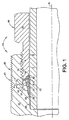
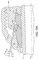
図2は、図1に示す例示的な継手の第1または前部の帯金の拡大断面図である。第1帯金20は概ね環状部であり、管端Tの外側表面S上を滑る概ね円筒形の内壁24を備えている(図1を参照のこと)。第1帯金20は外側表面26を有し、この外側表面は、前側部分28から後側部分30へ概ね円錐形になるように外方向へ先細になっている。前側部分28は、鋭利な前縁32と、円い鼻部34とを含むことができる。後側部分30は、カム表面38を形成する切頭円錐形(frusto conical)の凹部36を含む。先細の外側表面26は、軸方向に整列したフランジ40へと収束することができる(ここで、軸Xは導管および継手10の長手方向中心軸である)。
FIG. 2 is an enlarged cross-sectional view of the first or front band of the exemplary joint shown in FIG. The
図3は、図1に示す例示的な継手の第2または後部の帯金の拡大断面図である。第2帯金22は概ね環状部であり、管端Tの外側表面S上を滑る概ね円筒形の内壁42を備えている(図1を参照のこと)。第2帯金22は、鼻部46と、軸方向に延びる外側表面44とをさらに含み、この外側表面は、帯金の後側部分48の周りで延びている。鼻部46は、鋭利な前縁50と第1テーパ部分52とを含み、この第1テーパ部分は、鋭利な縁部50から後部48に向かって、例えば約15度のすくい角αで延びている。第1テーパ部分52は、例えば半径等の第1湾曲部分56に沿って、第2テーパ部分54に移行または融合する。第2テーパ部分54は、選択的に半径とすることのできるコーナーまたは縁部58にて、軸方向部分44に移行または融合する。第2テーパ部分54は、例えば約35度等の角度βで延びる。
FIG. 3 is an enlarged cross-sectional view of the second or rear band of the exemplary joint shown in FIG. The
第2帯金22は、被動表面(driven surface)62を有する後端部60をさらに含む。被動表面62は、例えば約5度等の角度δで半径方向外側へ延びる(法線から軸Xまでを参照)。被動表面62は、第2湾曲部分64に沿って軸方向部分44に移行または融合する。
The
図4〜図5は、図1に示す例示的な継手のナットの断面図を示す。ナット16は、全体に円筒形の形状を有し、組付け中に管端Tを受ける中央の孔66を画定する。ナット16は前端68を有し、この前端は、ソケット、凹部、またはケージ70を画定する。ソケット70は、第1円筒形部分72と、切頭円錐形部分74とによって画定され、この切頭円錐形部分は、ナット16の後端75へ向かって半径方向内側へ先細になっている。切頭円錐形部分74は駆動表面(drive surface)を形成し、この駆動表面は、締上げ中に第2または後部の帯金の被動表面62に接触する。駆動表面74は、例えば約15度等の角度τで形成される。角度τは角度δと異なるので、後部帯金22の被動表面62は最初に外半径64にて駆動表面74に接触する(図7を参照のこと)。差角Φ(ここでΦ=τ−δ)により、ナット16と第2帯金22との間の最初の接触部が管端Tから半径方向に離間していること、したがって、被動表面62と駆動表面74との間の接触部が同一平面にないことが確実になる。
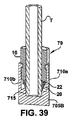
4-5 show cross-sectional views of the nuts of the exemplary joint shown in FIG. The
ソケット70は、軸方向に延びる概ね円筒形の壁またはカートリッジ76内で形成される。カートリッジ76は、後部帯金22と前部帯金20の後側部分30の少なくとも一部分とをその中で保持するように寸法されて、ナットおよび帯金アセンブリまたはカートリッジ・ナットアセンブリ78を形成する(図10を参照のこと)。本明細書において使用するカートリッジという用語は、継手部材の概念を簡略に参照したものであり、本事例では、アセンブリの嵌合継手部材が取り外される際でも、雄ねじ付きナット16は、雄ねじ付きナットと共に1つ以上の帯金を保持できる構造を有する。したがって、カートリッジ・ナット16および1つ以上の帯金20、22を含むカートリッジ・ナットアセンブリ78は、アセンブリが取り外されたとき、あるいは手動固締状態で単に本体12内に据付けられたときに、帯金およびナットを共に保持するために使用され得る。
カートリッジ・ナット16内で1つ以上の帯金20、22を保持するには、最終的な締上げの前、または嵌合継手部材へと最初に組付ける前であっても、多くの異なる技術を使用することができる。例えば、非汚染性の接着剤または粘着剤を使用して帯金20、22を適所で維持し、接着剤は締上げ力を下回るまでその把持を解放することができる。別法として、カートリッジ壁76を半径方向内側へ僅かに緊縮し、その中で帯金20、22を保持してもよい。さらに、締上げの際に潤滑剤へと分解する粘着剤を使用して、締上げトルクの低減を助長してもよい。本明細書で開示する実施形態において、カートリッジ・ナットアセンブリ78として部品を保持するためには、或る道具が使用される(図10を参照のこと)。
There are many different techniques for holding one or
図5を参照すると、カートリッジ76はテーパ部分82を含むことができ、このテーパ部分は、ナット16の後端75へ向かって半径方向外側へ先細になっている。テーパ部分82は、例えば約45度等の角度θで延びている。
Referring to FIG. 5, the
ナット16は道具係合部80をさらに含み、これによって、トルクレンチまたはその他の道具を使用して継手10を固締し締上げることができる。図1の例示的な実施形態における道具係合部80は、六角部分80として実現されている。道具係合部80は様々なやり方で形成することができる。例えば、ナット16は鍵穴を含むことができ、このことにより、対応する有鍵レンチを使用して、図21および図22A〜図22Dに関して説明するように、継手を固締し締上げることができる。
The
ナット16は、ねじ18と道具係合部80との間に、外径が多少低減された頚部77をさらに含むことができる。頚部77を使用して、トルクによる締上げと旋回による締上げとの両方に関して適切な締上げを検証する固有の検測機能を提供することができる。固有の検測とは、継手が適切に組付けられ締上げられたという表示を組付け者に提供する、継手自体(個別の道具または計器と対比して)に関連する構造または特性を意味する。固有の検測機能は多種の構造または特性により実施することができ、そのうちの幾つかの例が、国際出願第03/07739号および米国特許出願第10/711,353号、ならびに米国特許第6,640,457B2号に開示されている。本明細書では参照によりそれらの開示全体を完全に援用する。継手10の適切な締上げを確認するには、公知なやり方で隙間ゲージを使用することもできる。
The
図6を参照すると、雌ねじ付き本体12は、軸X上に中心のある概ね円筒形の部品である。本体12は、前側端部84にて開口83を有し、管端Tを受けるようになっている。中央の孔86は本体12を延在し、流体流路を画定するポート88を形成する。ポート88は、別の部品、例えば弁、T形、エルボ、マニホルド等との流体連通を確立するのに使用してもよい。雌ねじ付き継手部材12は個別のスタンドアロン型部品として示しているが、別法として、それにより雄ねじ付き継手部材と流体接続できるこの部材の特性を、一般に流体ポートと称されるバルク本体85、例えばマニホルド、弁、ポンプ、タンク等に組み込んでもよいということに留意すべきである。
Referring to FIG. 6, the internally threaded
雌本体は、肩部90を形成するカウンターボア89をさらに含む。管端Tは、本体12に受けられる際、肩部90に突き当たる。カウンターボア89は、継手10の締上げの際に管端Tの周りでの密閉の形成を助長するように、肩部の方へ僅かに先細にすることができる。
The female body further includes a
雌継手部材12は、第1テーパ表面、例えば切頭円錐形表面92と、第2テーパ表面、例えば切頭円錐形表面94とをさらに含む。第1切頭円錐形表面92は、本体12内に第1または帯金カム表面を形成し、軸方向でカウンターボア89の前側端部に近接することができる。第2切頭円錐形表面94は、本体12内に第2またはカートリッジカム表面を形成し、軸方向で第1カム表面92の前側端部に近接または接近することができる。第1または帯金のカム表面は角度σにて形成される。角度σは、第1帯金20の鼻部34によりカム作用が最適化されるように選択することができる。代表的な二帯金継手および一帯金継手において、この角度は約20度であるが、約10度〜約45度の任意の好ましい値としてもよい。
The
第2またはカートリッジカム表面94は角度ρにて形成される。本事例では角度は約45度であるが、必ずしもこの角度でなくてもよい。角度σと角度ρとは同じであってもよく、相互に異なっていてもよい。本明細書の図では角度は相違しており、従って、2つのカム表面92、94を接合する放射状段96が存在する。この段は放射状であってもよく、またはその独自の角度を有してもよく、または先細になっていてもよく、または必要に応じてその他の外形を有してもよい。
The second or cartridge cam surface 94 is formed at an angle ρ. In this example, the angle is about 45 degrees, but this angle is not necessarily required. The angle σ and the angle ρ may be the same or different from each other. In the figures herein, the angles are different, so there is a
本体12は、雄ナット16上のねじ18と螺合可能に嵌合する雌ねじ14をさらに含む。本体84は、ポート86を閉鎖または排除することにより、例えば流体ラインの端部に蓋をするのに使用できるようなキャップへと形成してもよいということに留意すべきである。本体12には六角平担部を提供して、締上げ中にナット16が締め付けられている間、本体を維持するのを促進することができる。当然ながら、締上げは、継手部材間、この場合はナット16と本体12との間の相対的な軸方向平行移動を伴うが、この軸方向平行移動は、どの継手部材が維持されており、どの継手部材が旋回されているかにかかわらず、ナットと本体との間の相対的回転により行われる。非ねじ込み式連結の場合、締上げは、2つのねじ込み部材以外の手段による、例えばクランプ装置により外力で合わされた2つの部材による、2つの継手部材間の相対的な軸方向平行移動を伴う。
The
本体12は、帯金20、22の概ね半径方向外側に形成される、加工硬化した部分81も含むことができる。管把持装置20、22の半径方向外側にすることに加え、与えられた用途によっては、必要に応じて、加工硬化する量および場所を選択することができる。加工硬化した部分は、継手本体12の前側端部84から少なくとも放射状段96の半径方向外側の場所へと延びるのが好ましい。一方で、加工硬化した部分は、例えば第1カム表面92の後端の半径方向外側の場所へと延びるか、または本体12の外面の長さ部分全体を延びることができる。加工硬化は、継手部材12の外側部分にて材料を塑性変形することにより達成される。材料は種々のやり方で塑性変形することができる。例えば、加工硬化は、概ね圧延した一連の周方向リブを生成することにより、または継手本体12上で雄ねじ98を圧延することにより達成することができる。
The
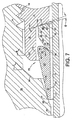
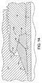
図7および図8は、帯金の領域を拡大した継手10を、手動固締状態および締上げ状態でそれぞれ示す。図7の手動固締状態において、第1または前部帯金の鼻部28は、帯金カム表面92により形成されたカム口の内部で部分的に位置決めされている。後部帯金22は、ナット16の駆動表面74に差角Φで係合することに留意されたい。このことは、締上げ中に、第2帯金22の後端部60が、管端Tの外側表面Sから半径方向外側に移動するかまたは留まることを確実にする。同時に、後部帯金22の鼻部46は、鋭利な縁部50が管表面Sへ咬合するかまたは切り込むように塑性変形して、強力な管把持肩部100と流体密封止とを生成する。帯金鼻部46は、円筒形壁42の一部分102が管壁表面Sに抗して半径方向に圧縮され、咬合部100から軸方向に離間した表面に抗して後部帯金22をかしめるかまたは食い込ませるようにも枢着する。放射状で高圧縮となり後部帯金22の食い込んだこの領域は、咬合部または切り込み100が、振動からの優れた保護を提供する。したがって、後部帯金22は、変形の際に枢着して、締上げの際に咬合部または切り込み100と帯金の後端60との間の食い込み領域102に作用する一方で、後端部60を、半径方向外側に移動させるか、または管端Tの外側表面Sから半径方向外側に離しておくように設計される。食い込み領域102の厳密な場所は、とりわけ帯金22の寸法により決まることになる。幾つかの事例において、食い込み領域102は、咬合部または切り込み100に近接させることができるが、別の事例では、食い込み領域は咬合部または切り込みから軸方向に離間させておくことができる。或る事例において、食い込み領域102を、管端をかしめる凸状の外形によりさらに特徴付けることができる。
FIGS. 7 and 8 show the joint 10 with an enlarged band area in a manually tightened state and a tightened state, respectively. In the manually clamped state of FIG. 7, the first or
2つの継手部材12、16間の相対的な軸方向平行移動は、カートリッジ76の前側テーパ表面82が、本体12の第2テーパ表面94に対して接触しカム運度するように実施される。カートリッジ76とv字表面94との間の接触部はコイニング様の作用を生ずるので、カートリッジ・テーパ表面82は、カム表面94に対して強力な流体密封止を形成する。同時に、前部帯金表面は、特に半径34にて、第1カム表面92に対する密閉を形成する。前部帯金20は、任意で管壁Sへとかしめるかまたは咬合して、管把持を提供することができる。
The relative axial translation between the two
帯金20、22の主な機能とは、外部システムが誘起する振動からの疲労に対する抵抗に加えて、流体密封止および管把持を生成することである。前部帯金20は、主として本体12および管外側表面Sに対する流体密封止を提供するのに使用されるのに対して、後部帯金22は、管外側表面Sに対し予備的に密閉するため、および優れた管把持を提供するのに使用される。複数の帯金、またはこのような応用例では単一の帯金の特別な幾何学形状および働きを、特定の用途のために適宜、使用される材料の種類に応じて選択することができる。例えば、後部帯金22には、帯金の円筒形内壁42内に1つ以上の凹部を提供することができ、帯金の被動表面62は輪郭をつけることができる。さらに、帯金20、22の一方または両方を例えば低温浸炭工程により焼入れして、耐食性である非常に硬質の帯金を提供することができる。焼入れは、帯金表面の一部分または全部にわたって施すことができる。帯金に施すことのできる焼入れおよび幾何学形状概念は、或る数の付与済み特許、例えば、本発明の譲受人に付与された米国特許第6,629,708号、第6,547,888号、第6,165,597号、第6,093,303号(その開示全体を参照により本明細書に完全に援用する)、ならびに、PCT国際公開第WO02/063195A2号および第WO02/063194A3号(これらも参照により本明細書に援用する)が開示している。一方で、このような特許およびその中の概念は、本発明に関しては本来例示的なものであり、限定の意味で解釈されるべきではない。多くの異なる焼入れ工程および多種多様な種類の幾何学形状を使用して、締上げ中の帯金の塑性変形を適切に制御し、適正な密閉および管把持を確実にすることができる。
The main function of the
管壁は、例えば15ksiの高圧下では、帯金20、22上を外側へ押し進めながら半径方向に拡張しようとする。カートリッジ76は、帯金20、22を半径方向で閉じ込め、密閉および管把持の損失を防止しようと働く。本体12は、前部帯金20を制約したとしてもさほど制約しないことに留意されたい。前部帯金20を加圧下で半径方向に閉じ込める応力は、後部帯金22での場合のように、カートリッジ76により達成される。本明細書の以下で検討する理由で、このことは重要である。特に図1において、加工硬化した任意の外側81も、カートリッジ76を、組付けた状態で半径方向に制約し支持することによって、より高い圧力を閉じ込めるように機能することにさらに留意されたい。
For example, under a high pressure of 15 ksi, the tube wall tends to expand in the radial direction while pushing the
締上げの際、カートリッジ76が本体12内の第2カム表面94に係合すると、カートリッジが流体圧力に対して密閉を形成することになるだけでなく、締上げトルクが激しく飛躍的に増加することに組付け者も注目するであろう。図9は、ナット16の変位に対するトルクの説明的データのグラフである。領域Aでは、帯金20、22が管Tと咬合し、本体のカム表面92および前部帯金カム表面38に抗してカム運動しつつ塑性変形する結果としてトルクが多少ゆっくりと着実に上昇することに留意されたい。しかし、カートリッジ76が本体12内の第2カム表面94に接触するとすぐに、領域Bのトルクは激しく飛躍的に増加する。適切な締上げに対応する適切なトルク値を選択することにより、継手10は、旋回ではなくトルクにより締上げることができる。したがって、継手10は単純なトルクレンチを使用して仕上げることができる。図9からわかるとおり、カートリッジの概念は、非常に緊密または急峻なトルク‐ナット変位比を提供する。このことは、帯金が変形するとトルクが次第に増加する以前の継手と顕著な対比を成している。段階的なトルク示数には過度に多くの要因が影響し得るので、以前の継手の適切な締上げを正確に計るのに常にトルクを使用することはできない。代わりに、以前の継手は通常、本体に対するナットの旋回または変位を計数することにより締上げられる。例えば、図9の領域Aは、トルクが、本体に対するナットの有意の変位以上にはほとんど増加できず、したがって、トルクが旋回または変位と良好に相関するのが妨げられていることを示す。
During tightening, when the
継手10は、カム表面94に例えば角度ρにて角度をつけることによりリメークすることができる。継手10をリメークするごとに、僅かにではあるが、カートリッジ・サブアセンブリは各リメークした本体内へとさらに前進する。非常に激しくトルクが増加するためには、角度ρを(軸Xに対して)90度に近づけることができる。この代替の配置により、トルクによる締上げについてはトルクが飛躍的に増加するであろうが、幾つかの事例において、最初の締上げ後に継手10をリメークする能力が低くなることがある。 The joint 10 can be remade by providing an angle to the cam surface 94, for example at an angle ρ. Each time the joint 10 is remade, the cartridge subassembly is further advanced into each remake body, albeit slightly. In order to increase the torque very violently, the angle ρ can be close to 90 degrees (relative to the axis X). This alternative arrangement may increase the torque dramatically for torque tightening, but in some cases may reduce the ability to remake the joint 10 after the initial tightening.
図8を参照すると、例えば図14および図21の代替の実施形態と同様に、トルクによる締上げをもたらすカートリッジ前側表面82と本体テーパ表面94との間の接触部は、締上げ後にカートリッジに対して本体の放射状の支持をもたらす。これらの実施形態の使用時のこの特性は、トルクによる締上げ機能性に加えて、継手をより高圧で使用することをさらに容易にする。
Referring to FIG. 8, as in the alternative embodiments of FIGS. 14 and 21, for example, the contact between the
その他の実施形態を使用して、カートリッジ76を本体12に係合させずに、トルクによる締上げをもたらすことができる。例えば、図19〜図20を参照して以下で説明するように、トルクによる締上げをもたらすやり方で、帯金を、本体に係合するように設計することができる。さらに、ナット16および本体12の、概ね放射状の任意の2つの表面が、継手10の適切な締上げの際に係合して激しいトルク増大を提供するようにこれらを設計することができる。例えば、継手本体上の外面を、完全な締上げの際にナットの外面に係合するように設計することができる。これらの表面は、カム表面94およびカートリッジ・テーパ表面82でのように、継手のリメークが可能となるように角度をつけることができる。
Other embodiments can be used to provide a torque-up without engaging the
本発明による継手は、12ksiを下回る加圧、さらには8ksiの加圧において使用することができるが、8ksiを超える、さらには12ksiを超える、より高圧の定格の継手として使用することに留意されたい。本発明の或る数の特性および態様は、次に検討するような、より高い定格圧力に耐える継手の能力に関連している。 It should be noted that the joint according to the invention can be used at pressures below 12 ksi, even at pressures of 8 ksi, but is used as a higher pressure rated joint above 8 ksi or even above 12 ksi. . Certain features and aspects of the present invention are related to the ability of the joint to withstand higher rated pressures, as discussed next.
本発明は、伝統的な雌式継手とは違って、帯金20、22、特に前部帯金20が、雌継手部材ではなく雄継手部材により、圧力に抗して半径方向に制約される継手10を提供する。換言すれば、前部帯金20は、以前の雌継手の設計と同様のやり方でカム表面92と係合するが、カートリッジ76により半径方向に制約されて圧力に抗して維持される。
The present invention differs from traditional female joints in that the
ステンレス鋼製の継手については、ナット16は、例えばバーストックから機械加工できるような加工硬化した部品とすることができる。というのも、より高圧下に帯金20、22を制約するのに充分強くなければならないからである。一方で、雌本体12は、加圧下で帯金20、22を保護するようには必ずしも活用されないので、加工硬化した材料から形成する必要がない。従って、本体12は、例えば鍛造または鋳造等により、焼きなましした材料から形成することができる。継手本体12を、例えばオーステナイト系ステンレス鋼を鍛造または鋳造することにより形成することは、硬化したバーストックから機械加工により形成するよりも著しく安価であり得る。このことは、継手本体が、複雑な形状、例えばT形またはエルボである(かまたはその一部である)場合に特に当てはまる。結果として、本発明により著しい費用の節約を実現することができる。さらに、熱処理により硬化できないオーステナイト系ステンレス鋼を活用して、鋼を加工硬化する必要なしに本体を形成することができる。オーステナイト系ステンレス鋼から本体を形成することは、その優れた耐食性に起因して、多くの用途において有利である。
For stainless steel fittings, the
本体を焼きなましして、より高圧の定格または作動圧力にて機能できる継手10を提供できることにより、その利用可能な用途が大いに拡張される。継手本体12は、例えば、より軟化に焼なましした金属製の種々の流体成分、例えばポンプハウジング、シリンダヘッド、マニホルド、タンク等において雌ポートを提供することにより形成することができる。一方でやはり、さらなる代替の実施形態が、必要な場合に、特に、より高圧の定格圧力または作動圧力であっても、本体12も加工硬化した材料から形成できること、あるいは本体の一部分を加工硬化できることを実現する。
The ability to anneal the body to provide a joint 10 that can function at higher rated or operating pressures greatly expands its available applications. The
継手本体12の一部分を選択的に加工硬化することにより、継手は、継手10の漏出を引き起し得る変形または損傷なしに高い内圧に耐える。したがって、継手本体を選択的に加工硬化することは、管把持装置20、22を加圧下で保護するのに本体を活用しないことと同様の利点を提供する。具体的には、本体12は、硬化させたバーストックではなく、焼きなましした材料から形成することができる。そうすることにより、継手10は、より高圧の定格圧力または作動圧力にて機能するが、以前の高圧の継手以上に著しく費用を節約して実現することができる。
By selectively work hardening a portion of the
例えば継手10を15ksiにて定格とする場合、業界の慣習によると、通常、その圧力定格の4倍(4:1の管把持作業率)以上の水圧下で、すなわち60ksiで試験される。統計的に有意な数の継手が、60ksi以上で試験され、継手は、予想される作動圧力の少なくとも4倍まで漏出なく持ち堪えることが、高い信頼性により確実に予測される。本出願人らは、本発明による継手10が、約75ksi以上までの圧力を維持でき、したがって少なくとも5:1の管把持作業率を提供することを発見した。したがって、継手10の一部分を選択的に加工硬化することにより、継手本体20には比較的軟質の鍛造品を使用することも可能となる。
For example, when the joint 10 is rated at 15 ksi, it is usually tested under water pressure that is at least four times its pressure rating (4: 1 tube gripping rate), ie, 60 ksi, according to industry practice. A statistically significant number of joints have been tested at 60 ksi and above, and it is reliably predicted with high reliability that the joints will withstand at least four times the expected operating pressure without leakage. Applicants have discovered that the joint 10 according to the present invention can maintain pressures up to about 75 ksi and higher, thus providing a tube gripping rate of at least 5: 1. Therefore, a relatively soft forged product can be used for the
本明細書の上で説明したように、継手10は、継手の一部分81を塑性変形することにより、選択的に加工硬化することができる。帯金20、22の半径方向外側にある継手10の一部分は、継手本体12上で1組の周方向リブまたは雄ねじ98を圧延することにより加工硬化される。加工硬化は、継手本体12またはその他の部品の機械加工と同時に実施することができる。具体的には、継手本体12等の部材は通常、そこで種々の機械加工作業が連続して行われる複数の指数位置を有する複数のスピンドルマシン上で機械加工される。これらの作業の1つはリブまたはねじ98を圧延して継手本体12を加工硬化することであり、本体は、硬化するために(その機械から離れて)個別の作業を受ける必要はない。部品12は、機械上へいったん装荷し、ねじ98を形成するために加工硬化を含む機械加工を行い、取出すことができる。
As described hereinabove, the joint 10 can be selectively hardened by plastically deforming a
さらに、加工硬化工程において形成できる雄ねじ98は、継手10にとってより有用な形状を提供することができる。特に、ねじ98を使用して、或る継手増強部を継手12に装着することができる。例えば、1つ以上のロックナットを雄ねじ98にねじ込み、継手10をさらに強化することができる。付加的な例としては、ねじ98を使用して、継手本体12をパネルに装備するか、または管Tを支持できる手段を装着することを含み、継手10内で管を保持することを支援したり、外部管の振動の影響の減衰を支援したり、またはその他の機能を支援したりすることができる。
Furthermore, the
帯金を焼入れまたは浸炭することができるので、本明細書において開示する継手10では、15ksi以上の、より高圧の定格をさらに達成することができる。このことにより、帯金20、22は、加工硬化した導管、例えば、より高圧の用途に必要な厚肉の管類、または1/8の硬質またはひずみ硬化された材料等に対して咬合し密閉することができる。継手10は、実質的なバルク材料を有する後部帯金22を提供して、導管を把持する際に帯金をより強力にすると同時に導管に咬合できるようにする。さらに、カートリッジ76により第2カム表面94に対して形成された密閉は、前部帯金20により第1カム表面92に対して形成された本体の密閉に、補助的または予備の密閉を提供する。第2カム表面94に対するカートリッジの密閉は、より軟化に焼なましした本体を使用することにより促進することができる。
Since the band can be quenched or carburized, the joint 10 disclosed herein can further achieve a higher pressure rating of 15 ksi or more. This allows the
一方で、本発明は、ステンレス鋼の材料と共に使用されることに限定されない。例えば、特に代替燃料車両の自動車業界は、種々の継手および導管用に、ステンレス鋼ではなく炭素鋼を追求することを決めてもよい。本発明は、炭素鋼を焼きなましにより硬化できるとはいえ、炭素鋼を使用する際にも利点を提供する。これらの利点は、(本明細書の以下でさらに説明する)より簡単な組付けのためのカートリッジ概念を含んでおり(ただしこれに限定されない)、カートリッジにより本体に対する密閉を提供して、トルクに対し旋回によらずに締上げの可能な継手を提供する。 On the other hand, the present invention is not limited to use with stainless steel materials. For example, especially the alternative fuel vehicle automotive industry may decide to pursue carbon steel rather than stainless steel for various fittings and conduits. The present invention also provides advantages when using carbon steel, although carbon steel can be hardened by annealing. These advantages include (but are not limited to) a cartridge concept for easier assembly (discussed further hereinbelow) and provide a seal against the body by the cartridge to reduce torque. Provided is a joint that can be tightened without turning.
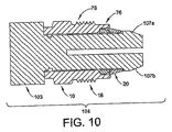
図10は、図1に示す例示的な継手のナット16および2つの帯金20、22の長手方向断面図であり、ナットおよび2つの帯金を道具103上に据付けている。道具103は、継手10を仕上げる前にカートリッジ・ナット16と1つ以上の帯金20、22とを単一のアセンブリ78として保持するのに都合のよいやり方を提供する。したがって、アセンブリ78および道具103は共に、嵌合継手部材、例えば雌継手部材12等内に据付け可能な単一のユニット104を提供するので、組付け者は、2つの継手部品を取り扱いさえすればよい。結果として、組付けるのに弛んだ帯金がなくなるので、帯金は、製造者のところで据付けられて据付け誤差を回避することができる。粘着剤の使用等、カートリッジ・ナットアセンブリを提供するその他の技術は本明細書中で上述された。
FIG. 10 is a longitudinal cross-sectional view of the exemplary
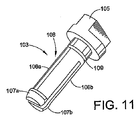
図11は、道具103の例示的な実施形態の斜視図を示す。図10および図11を参照すると、道具103は、手動で、またはプライヤ等の単純な道具により把持できる頭部105を含む。道具103は単一の可塑性エレメントであるが、適宜、その他の材料を使用してもよい。頭部105から可撓性フィンガ106aおよび106bが延びており、これらのフィンガはその末端でそれぞれ、隆起した唇部107aおよび107bを含む。唇部107a、107b、および頭部105は溝穴またはキャリッジ108を画定し、該溝穴上へ、カートリッジ・ナット16および帯金20、22を据付けることができる。可撓性フィンガ106a、106bは、ナット16、そして帯金20、22が唇部107a、107b上を頭部105へ向かって充分移動できるように半径方向に圧縮する。これらの部材がいったん唇部107a、107bを過ぎるとフィンガ106a、106bは外側へ反発し、したがって、帯金20、22およびナット16を共に単一のアセンブリ78として道具103上で保持する。
FIG. 11 shows a perspective view of an exemplary embodiment of the
図12Aおよび図12Bは、道具103を使用して継手10を仕上げる際の種々のステップを示す。継手10を仕上げるには、アセンブリ78が雌本体12へと挿入され、組付け者は、指の圧力を容易に使用して、ナット16および本体12を回転させ螺合可能に係合する(またはナットを別の本体の雌ポートへと回転させる)ことができる。ナット16が本体12へとねじ込まれる際、唇部107a、107bは、本体12内部の表面、この場合は第1カム表面92に係合することになる。アセンブリ78および道具103を本体12内へとさらに軸方向に変位させると、本体12に抗するカム作用に起因して、フィンガ106a、106bが半径方向に圧縮される。
12A and 12B illustrate various steps in finishing the fitting 10 using the
アセンブリ78および道具103を継続して軸方向に変位させると、フィンガ106a、106bは、唇部107a、107bが帯金20、22およびナット16の内径よりも寸法的に小さくなるように充分に圧縮する。したがって、道具103は帯金から自己離脱する。これが生じると、道具103は、アセンブリ78および本体12から容易に引き抜くことができる。道具103は、任意の寸法の継手に容易に適合できること、および、アセンブリ78についての情報、例えば寸法、材料、締上げトルク等を示すために、色分けするかまたはその他の目印を提供することもできることに留意されたい。例えば、溝109またはその他の好ましい印、目印、あるいは構造を道具103上で提供して、継手は手動固締位置に適正に仕上げられたので道具を容易に除去できるという視覚的表示を、使用者に提供することができる。図12Bに示すように、道具の唇部107aおよび107bの前側端部は、本体12の表面へと任意に係合して、本体12内への道具のさらなる軸方向前進を遅らせることができる。この事象は、トルクの著しい増加として操作者に容易に識別され得るので、操作者は道具を除去できることを触感によって理解する。
As the
図13〜図18は、本発明の別の例示的な継手を示す。この実施形態の機能的特性のうちの多くは、特に注記する以外には上述の実施形態と同様である。図13〜図18の例示的な継手110は、雌ねじ付き本体112と雄ねじ付きナット114とを含む。本体112は、第1カム表面116と第2カム表面118とを含む。第2カム表面118は、ナット114の一部として形成されたカートリッジ124の内側端部122上で、締上げ中に角度のついた表面120と係合する(図14)。表面120の角度θは、継手110の長手方向中心軸Xに対して約45度とすることができるが、適宜、その他の角度を使用することもできる。一方で、この実施形態において、カートリッジ124は、先細のまたは円錐形の壁126を含み、この壁は、後部帯金130および前部帯金132の少なくとも一部分用に先細のソケット128を形成する。ナットの撤回中、帯金は壁126との接触から離脱できるので、先細のソケット128は取り外し中のナット114の撤回を容易にする。壁126は、長手方向中心軸Xに対して約5〜約20度の角度εにて先細にすることができるが、適宜、その他の角度を使用することもできる。後部帯金130は、先細の外壁部分134を含み、取り外しを促進することができる。そして、前部帯金132も先細の外壁部分136を含むことができる。後部および前部帯金の先細の外壁134、136は、所望の効果を達成するのに好ましい角度、例えば軸Xに対して約5〜約20度にて形成することができるが、必要に応じて、その他の角度を使用することもできる。したがって、本発明は、取り外しの際にナット114および2つの帯金130、132のアセンブリ全体を撤回できる、あるいはナットを個別に除去できるカートリッジ設計を意図している。先細のソケットを内含することは、より高圧の用途にとって特に有用となることがある。というのも、締上げの際、または高圧の用途の際、帯金はソケット壁に接着または「溶接」されないことになるからである。取り外し中にトルクが帯金に加わらないようにナットが撤回されると、帯金は、先細のソケット壁から離脱することになる。このことは、継手の適切なリメークを確実に達成することの役に立つ。
Figures 13-18 illustrate another exemplary coupling of the present invention. Many of the functional characteristics of this embodiment are similar to those described above, except as noted. The
図13Aおよび図14Aは、本発明の代替の実施形態を示す。この実施形態は、図13〜図18の実施形態と幾つかの特性を共有しているので、同様の特性を表すのに同様の参照符号を使用する。この場合、前部帯金132、後部帯金130、ナット114、および本体112がある。ナット114は、先細のまたは円錐形の壁126を有する前側カートリッジ124を含む。カートリッジ壁126は、継手の長手方向中心軸Xに対して角度εにて形成されている。前部帯金は、本事例では長手方向軸Xに対して角度μにて形成される輪郭付き外壁部分136を含む。角度μは、角度εと等しくてもよく、あるいはこれとほぼ等しくてもよいが、幾つかの事例においてμ≠εであると望ましいであろう。例えば通常、前部帯金の後端は、後部帯金130により加えられる力に起因して、締上げ中、管壁Tから離れるように半径方向に移動しようとする。差角ω=μ−εがあることによって、輪郭付き表面136は、より大きな表面積にわたってカートリッジ壁126に接触することになる。したがって、応力集中が低減されて、表面126を摩耗し、前部帯金がリメーク後にカートリッジ・ナットに「粘着」する可能性を低減させることに役立つ。このことは、前部帯金が、例えば焼入れした表面を有する硬化した部品である場合に特に当てはまる。角度ωは、任意の好ましい角度、例えば2度等とすることができるが、特定の設計では、2度より大きくても小さくてもよい。したがって、表面136は、高圧下で帯金を支持し、カートリッジ・ナット114による摩耗を低減する耐荷重表面として機能する。
13A and 14A show an alternative embodiment of the present invention. Since this embodiment shares some characteristics with the embodiments of FIGS. 13-18, like reference numerals are used to represent similar characteristics. In this case, there is a
前部帯金の輪郭付き表面136は、概ね半径方向に延びるフランジ137によって示されるように形成され得る。このことにより、前部帯金とフープ応力負荷とに、より大きなバルクを提供し、より高圧に耐えること、およびより高圧にて後部帯金を閉じ込めることが助長される。
The front band contoured
多くの用途において、本体およびナットは、継手がより高い定格圧力を支持できるように、選択的なひずみ硬化(本明細書の上で説明したような)により、ひずみ硬化または焼きなましすることができる。摩耗および粘着をさらに低減するために、カートリッジ・ナット、特に内面126を、例えば本明細書の上で説明した工程、あるいはその他の好ましい焼入れ工程により、焼入れすることができる。本明細書において上述の援用された参考文献における工程は特によく適している。というのも、それらの工程が、優れた耐食性と、摩耗を排除する非常に硬質の表面とを提供するからである。幾つかの応用例では、ナット114全体を焼入れすることができる。このことは、継手のリメーク中、ナット114の管孔TB(図14Aを参照のこと)が管端T上へと潰れないことを助けるという利点を有する。本明細書において説明したように焼入れした本体114を用いて、摩耗なしの50以上のリメークが観察された。例えば、焼入れした表面126、特に低温浸炭した表面は、高価な潤滑剤が不要であり得る。というのも、焼入れした表面上に形成された酸化物と共に、単純な油またはその他の好ましい潤滑剤を使用することができるからである。
In many applications, the body and nut can be strain hardened or annealed by selective strain hardening (as described hereinabove) so that the joint can support higher rated pressures. To further reduce wear and sticking, the cartridge nuts, and particularly the
図19および図20は本発明の別の実施形態を示す。図19は、手動固締位置にある継手の長手方向断面図であり、図20は、締上げ位置にある継手を示す。この実施形態において、継手150は、本明細書の上で説明した実施形態の設計と同様であり得るナット152および本体154を含む。一方で、この実施形態では、カートリッジ156の軸方向の長さ155が短縮されている。というのも、カートリッジ156は、後部帯金158を保持するのみに使用しているからである。前部帯金160はもはやカートリッジ156内には含まれていない。図10〜図12に示した道具と同様の道具を使用して、上で説明した実施形態におけるように、単一の部材アセンブリを維持することができる。
19 and 20 show another embodiment of the present invention. FIG. 19 is a longitudinal cross-sectional view of the joint in the manual clamping position, and FIG. 20 shows the coupling in the clamped position. In this embodiment, the fitting 150 includes a nut 152 and a
本事例において、前部帯金160は、半径方向に延びる拡大フランジ162を含む。フランジ162は、継手本体154の孔164内に嵌まるように寸法されている。フランジ162は、フランジの前側部分169において、駆動後部表面166と密閉表面168とをさらに含む。密閉表面168は、角度θ(例えば約45度等)で延びる。密閉表面168は、締上げ中に本体154の第1カム表面170に係合する。このことにより、信頼度の高い補助的な圧力封止と、機能において上の実施形態のカートリッジの前端の係合と同様のトルク設計への締上げとが提供される。
In this case, the
本事例における被動表面166は、概ね放射状であり、締上げ中にカートリッジ156の前端172に係合するので、カートリッジは前部帯金160を前方へ直接駆動する。後部帯金158もまた、カートリッジ156が前部帯金フランジ162に係合するまで、前部帯金160を前方へ駆動する。前部帯金160は先細の鼻部174をさらに含み、この鼻部は本体154の第2カム表面176に係合する。フランジ162は、フランジが特に加圧下で本体壁178により支持されるように、適切に寸法設計することができる。したがって、本体154は、加工硬化した原材料から形成することができ、あるいは、焼きなましした本体に選択的に加工硬化を施すことができる。
The driven
図21は、本発明の別の例示的な継手の長手方向部分断面図である。この実施形態において、継手180は、本明細書の上で説明した実施形態の設計と同様であり得る本体182および帯金184、186を含む。一方で、この実施形態において、継手180は、異なるナット188を含む。ナット188は、管端Tを受けるための通路190を画定する概ね円筒形の形状を有する。ナット188は、雌継手部材、例えば継手本体182等の雌ねじ194と係合するための雄ねじ192を有する。ナット188は、1つ以上の鍵穴198を含む後面または外面196を有する。各鍵穴198は、有鍵の駆動工具202、202’の鍵タブ200を受けて、これにより駆動されるように適合されている。
FIG. 21 is a longitudinal partial cross-sectional view of another exemplary coupling of the present invention. In this embodiment, the joint 180 includes a
有鍵の駆動工具202、202’は、多種多様な異なる形態をとることができる。好ましい駆動工具の例としては、図22A〜図22Dに示す駆動工具202、202’を含む(ただしこれらに限定されるものではない)。ナット188内の1つ以上の穴198に係合するように構成された1つ以上の有鍵タブを含む任意の駆動工具を使用することもできる。
The
図22Aおよび図22Bで示す実施形態において、駆動工具は、断面が概ね矩形である細長いつまみ部分203を有する有鍵レンチ202である。つまみ部分203の断面形状は矩形以外とすることもできる。例えば、つまみ部分203は楕円形または円形の断面を有することもできる。鍵タブ200は、つまみ部分203からおよそ直角に延びている。鍵タブ200は、つまみ部分203から直角以外の角度で延びることもできるが、直角が好適である。鍵タブ200は、鍵穴198と嵌合して、有鍵レンチ202がナット188を充分に回転させて継手180を締上げることができるように適合されている。
In the embodiment shown in FIGS. 22A and 22B, the drive tool is a
鍵レンチ202は、つまみ部分203の中心軸206に沿って延びる隙間開口204も含む。隙間開口204は、鍵レンチ202が導管をまたいで管の干渉なくナット188に係合できるように寸法され位置決めされている。
The
図22Cおよび図22Dで示す実施形態において、駆動工具202’は、ナット188上の鍵穴198と係合するようになっている六角工具である。六角工具202’により、ナット188を、より伝統的な六角レンチを用いて固締したり、または弛めたりすることができる。図示する実施形態の六角工具202’は2つの本体半部243a、243bを含み、該本体半部には、2つの本体半部243a、243bを接合するために、対応する整列ピン246a、246b、および嵌合穴245a、245bが提供される。接合されると、2つの本体半部243a、243bは、管T(図21を参照のこと)を受けるための内部孔または隙間開口244を画定する。六角工具202’の二部材構成により、自由管端がアクセス不可能な管類、例えば流体システム内に既に据付けられている管類の周りに道具を組付けることができる。整列ピン246a、246b、および嵌合穴245a、245bには、いったん管Tの周囲の周りで組付けた本体半部243a、243bを接合したままにできる軽微な締まり嵌めを提供することができる(ただし必須ではない)。いずれの本体半部にも突出鍵タブ240a、240bが提供され、これらの突出鍵タブは、図21に示すナット188内の対応する鍵穴198と整列してこれに挿入されるようになっている。
In the embodiment shown in FIGS. 22C and 22D, the
円筒形のナット188を固締したり、または弛めたりするには、本体半部243a、243bを管Tの周りで接合し、突起240a、240bを鍵穴198内へ挿入する。その後、六角レンチ(図示せず)を六角工具の六角平担部に当て、固締方向または弛める方向に旋回して、ナット188を相応に調整する。調整が完了したら、六角工具202’を継手アセンブリから除去し、ナット188が引き続いて調整されないようにする。
To tighten or loosen the
ナット188の長さは、ナットが継手本体182へと完全にねじ締めされたときに、ナット96の後面196が本体182の端部と同一平面となるように、あるいはこれに隠れるように選択される。継手本体182から標準的な六角形状が突出しない結果として、ナット188が不注意により弛められたり、除去されたりする機会が低減される。というのも、継手180を取り外す能力は、特定の有鍵レンチ202を有する人員のみに制限されるからである。さらに、ナット188上で鍵穴198に異なる位置を提供することにより、特定のレンチと組み合わせて特定の製品(寸法等)を製造できるようにしてもよい。
The length of the
さらに、ナット188は継手本体182から突出していないので、組付けられた継手180は小さくなる。このことは、空間が重要な用途、例えば自動車用途において有益なことがある。最後に、ナット188は費用低減を可能にするので有益でもある。というのも、完全なナットは、表面的な効果のために(標準的な雌ナットで行われるように)六角形の範囲に選択的にねじにめっきを施したり、またはめっきを取り除いたりする必要なしに(ねじ192の潤滑のため)銀めっきできるからである。したがって、銀めっきは、ナット188全体を浸漬することにより達成することができる。
Further, since the
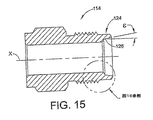
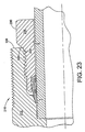
図23は、締上げ状態で示す本発明の別の例示的な継手の長手方向部分断面図である。この実施形態において、継手210は、本明細書の上で説明した実施形態の設計と同様であり得る本体212、ナット216、および帯金220、222を含む。一方で、この実施形態において、本体212は、適切な締上げの際にナット216上のテーパ表面226に係合する外側カム表面224を含む。外側カム表面224は、本体212の前側端部228上に設置することができる。ナット216のテーパ表面226は、本体212から離れるように軸Xから外側へ先細になっている。テーパ表面226は、例えば、六角部分230等の道具係合部上に設置することができる。
FIG. 23 is a partial longitudinal cross-sectional view of another exemplary joint of the present invention shown in a tightened condition. In this embodiment, the fitting 210 includes a body 212, a nut 216, and bands 220, 222 that may be similar to the design of the embodiments described hereinabove. On the other hand, in this embodiment, the body 212 includes an
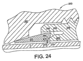
図24は、手動固締状態で示す本発明の別の例示的な継手の長手方向部分断面図である。この実施形態において、継手250は、本明細書の上で説明した実施形態の設計と同様であり得る本体252、ナット256、および第1帯金260を含む。一方で、この実施形態において、ナット256は一体型帯金262を含むが、この帯金は、第1帯金260に置き換えてもよく、または、図24に示すように、第2帯金として機能させてもよい。一体型帯金262の幾何学形状(例えば先細の外側表面部分264、半径部分266および268、鼻部270等の幾何学形状)は、鼻部が、カム表面、例えば第1帯金260の後側部分274上のカム表面272へと駆動されるのに応答して、一体型帯金の、適切な半径方向内側の枢着作用がもたらされるように選択される。継手において活用される一体型帯金の概念は、国際公開番号第WO02/063194A2号に開示されており、その開示全体を、本明細書において参照により完全に援用する。一方で、刊行物およびその中の概念は本発明に関して本来例示的なものであり、限定の意味で解釈されるべきではない。
FIG. 24 is a longitudinal partial cross-sectional view of another exemplary joint of the present invention shown in a manually clamped state. In this embodiment, the fitting 250 includes a body 252, a nut 256, and a first strap 260 that can be similar to the design of the embodiments described hereinabove. On the other hand, in this embodiment, the nut 256 includes an integral band 262, but this band may be replaced with the first band 260 or as a second band as shown in FIG. It may function. The geometry of the integrated strap 262 (eg, the tapered outer surface portion 264, the
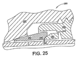
図25は、手動固締状態で示す本発明の別の例示的な継手の長手方向部分断面図である。この実施形態において、継手280は、本明細書の上で説明した実施形態の設計と同様であり得る本体282、ナット286、および第1帯金290を含む。一方で、この実施形態において、ナット286は分離可能な帯金292を含むが、この帯金は、第1帯金290に置き換えてもよく、または、図25に示すように、第2帯金として機能させてもよい。分離可能な帯金292は、壊れやすい繋ぎ部分294によりナット286に装着されている。継手280を部分的に締上げる際、分離可能な帯金292は、カム表面、例えば第1帯金290の後側部分298上のカム表面296に係合し、ナット286から外れるかまたは分離する。いったん分離すると、分離可能な帯金292は、本明細書の上の実施形態で説明した帯金と同様に機能する。継手において活用される分離可能な帯金の概念は、国際公開番号第WO02/063195A2号に開示されており、その開示全体を、本明細書において参照により完全に援用する。一方で、刊行物およびその中の概念は本発明に関して本来例示的なものであり、限定の意味で解釈されるべきではない。 FIG. 25 is a longitudinal partial cross-sectional view of another exemplary joint of the present invention shown in a manually clamped state. In this embodiment, the fitting 280 includes a body 282, a nut 286, and a first strap 290 that can be similar to the design of the embodiments described hereinabove. On the other hand, in this embodiment, the nut 286 includes a separable strap 292, which may be replaced by a first strap 290 or, as shown in FIG. It may function as. The separable band 292 is attached to the nut 286 by a fragile joint 294. When partially tightening the joint 280, the separable strap 292 engages the cam surface, eg, the cam surface 296 on the rear portion 298 of the first strap 290, and disengages or separates from the nut 286. . Once separated, the separable band 292 functions similarly to the band described in the embodiments above herein. The concept of separable straps utilized in fittings is disclosed in International Publication No. WO 02 / 063195A2, the entire disclosure of which is hereby fully incorporated by reference. On the other hand, the publications and the concepts therein are exemplary in nature with respect to the present invention and should not be construed in a limiting sense.
図26および図27を参照すると、カートリッジ・ナットアセンブリの概念は、単一帯金管継手300と共に使用することもできる。図示する実施形態は、図27の実施形態においてカートリッジ・ソケットを形成する内面が先細である以外は同様である。したがって、両方の実施形態において、雌ねじ付き本体302は、雄ねじ付きナット304を受ける。ナット304は、一端にて、軸方向に延びる概ね円筒形の拡張部308により形成されたカートリッジ306を含む。したがって、カートリッジ306は、帯金312の一部または全部を受けるソケット310を形成する。帯金312は先細の前側端部を含み、この前側端部は、帯金が塑性変形して本体302内で受けられる管端(図示せず)と緊密に把持・密閉係合するように、継手の締上げ中に先細のカム表面314に係合し、カウンターボア316に突き当たる。ソケット310は内面318により画定されるが、この内面は、図26の実施形態では概ね円筒形であり、図27の実施形態では先細である。帯金312は、本明細書の上で説明したような輪郭付き外側表面320を含むことができ、さらに、外側表面320とソケット310の内面との間に、本明細書の上で説明したような差角を含むことができる。帯金およびカートリッジ・ナットは、特別な用途では、完全にまたは選択的に、焼入れしまたは別様に硬化することができる。帯金312は、カートリッジ306のソケット310内で駆動表面324に係合する被動表面322をさらに含むことができる。最終締上げ中の帯金の変形を促進して、帯金が、管端に食い込む枢着効果を呈するようにするために、帯金被動表面322には輪郭をつけることができる。輪郭付き表面322は例えば凸状の形状とすることができる。被動表面322は、差角により駆動表面324に係合して、帯金の食い込みおよび枢着をさらに促進することもできる。
Referring to FIGS. 26 and 27, the cartridge nut assembly concept can also be used with a
図28は、道具または心棒103の使用の別の実施形態を示す。この実施形態において、道具400は、雌ねじ付きナット402、ならびに関連する前部帯金404および後部帯金406を受けて保持するように寸法されている。この配置は、単一帯金設計で使用することもできる。道具400の動作および使用は、本明細書において図10の実施形態を用いて先に説明したようなものとすることができる。道具400の使用により、製造者は、帯金およびナットが既に適切に組み合わされて、管端に据付けるための部品が、関連の雄ねじ付き本体(図示せず)を有する単一のサブアセンブリ410となったナット・帯金アセンブリを、最終使用者に提供することができる。道具400は把持部408を含むことができ、これにより、より簡単に道具を手動把握して、ナット402および帯金が関連の本体に組付けられた後に道具を除去することが可能となる。
FIG. 28 illustrates another embodiment of the use of the tool or
図29A〜図29C、および図30〜図39は、図10および図11に示す種類の道具の付加的な実施形態を示しており、そこでは、道具は、帯金が管端上へ少なくとも部分的に固締された後に、ナット、帯金、および/または管端を保護するための保護装置を提供するようになっている。図32に示すように、継手アセンブリのナットおよび帯金は、対応する継手本体、または、ナットと共に組付けるためのねじを有する事前固締具により、管端と共にしばしば事前に組付けられ、継手内での管端の将来的な据付けが促進される。保護装置、例えばキャップまたは保護カバー等は、このアセンブリのナット、帯金、および/または管端を少なくとも部分的に被覆することができ、流体システム内での据付前のアセンブリの格納中または移送中に、これらの部材の表面の損傷または汚染を防止することができる。 FIGS. 29A-29C and FIGS. 30-39 show additional embodiments of tools of the type shown in FIGS. 10 and 11, where the tool is at least partially loaded onto the tube end. Once secured, the protective device is intended to protect the nut, band, and / or tube end. As shown in FIG. 32, the nuts and straps of the joint assembly are often pre-assembled with the pipe ends, either by the corresponding fitting body or by pre-fasteners with screws for assembly with the nut, Future installation of pipe ends at will be facilitated. Protective devices, such as caps or protective covers, can at least partially cover the nuts, straps, and / or tube ends of the assembly, during storage or transfer of the assembly prior to installation in the fluid system In addition, damage or contamination of the surface of these members can be prevented.
本発明により意図される道具は、導管またはその他の接続具と共に組付けるために保持されるべき継手部材を含む任意の継手と共に使用することができ、継手には、本願において開示した継手、例えば単一帯金管継手、二帯金管継手、雌ねじ付きナットを備えた雄ねじ付き管継手、および、雄ねじ付きナットを備えた雌ねじ付き管継手を含む(ただしこれに限定されるものではない)。 The tool contemplated by the present invention can be used with any joint, including joint members to be held for assembly with conduits or other connectors, including joints disclosed herein, such as simple joints. Includes, but is not limited to, one-band metal fittings, two-band metal fittings, male threaded pipe fittings with female threaded nuts, and female threaded pipe fittings with male threaded nuts.
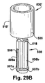
図29A、図29B、図29C、および図30の例示的な実施形態において、道具500は、手動で、または例えばプライヤ等の道具により把持できる頭部505を含む。道具500は単一の可塑性エレメントとすることができるが、適宜、その他の材料、または部材の組み合わせを使用することができる。道具の保持部分は、管端への将来的な組付け用に、ナットおよび帯金を維持する任意の形状とすることができる。これらの例では、頭部505から可撓性フィンガ506aおよび506bが延びて、保持部分または心棒506を形成する。フィンガ506a、506bは、それらの末端でそれぞれ、隆起した唇部507a、507bを含むことができる。唇部507a、507b、および頭部505は溝穴またはキャリッジ508を画定し、この溝穴には、図30に示すように、カートリッジ・ナット16および帯金20、22を据付けることができる。可撓性フィンガ506a、506bは、ナット16、次に帯金20、22が唇部507a、507b上を頭部505へ向かって移動できるように半径方向に充分圧縮する。これらの部材がいったん唇部507a、507bを過ぎるとフィンガ506a、506bは外側へ反発し、したがって、帯金20、22およびナット16を共に道具上で保持する。
In the exemplary embodiments of FIGS. 29A, 29B, 29C, and 30, the
例示的な実施形態において、保護部分が存在する。保護部分は、多種多様な異なる形状をとることができる。例えば保護部分は、ナット、帯金、および導管端のうちの1つ以上を完全に被覆するように適合させることができ、あるいは、保護部分は、ナット、帯金、および導管端のうちの1つ以上を部分的に被覆するように適合させることができる。この保護部分は、別の表面との接触から生じる損傷または汚染を防止することにより、継手部材の十分な保護を提供することができる。図29A、図30、図31、および図32に示す例示的な実施形態の道具500は、頭部505から延びて保護部分510を形成する一対のプロング(prong)510a、510bを含む。プロング510a、510bは、それらの末端でそれぞれ、内方突出物または突起512a、512bを含むことができる。突起512a、512bは、ナット16の外側表面内の凹部、例えばねじ止め17、または雄ねじと六角ナットとの間の空間と整列するように位置決めおよび寸法設計することができ、これによって、図31および図32に示すように、保護部分が、ナット16に組付けられたときに離れ落ちるのが防止される。プロング510a、510bは、保持部分506に関して任意の配向にすることができる。例えば、図29Aおよび図31の例示的な実施形態では、プロング510a、510bは、フィンガ506a、506bに対して垂直に配向されているが、図30の例示的な実施形態では、プロング510a、510bは、フィンガ506a、506bと平行に配向されている。道具500の頭部505は、保護部分510の上面または被覆表面を形成することができる。図29Aにより示す例では、図31および図32に示すように保護部分510をナット16、帯金20、22、および管端T上に組付ける際に管端Tを受けるように位置決めした孔515を頭部505に提供することができる。保護部分は、ナット16、帯金20、22、または管端Tを少なくとも部分的に封入するか、被覆するか、または保護する任意の構造、例えば図29Bおよび図29Cにそれぞれ示すようなカップ状の拡張部510’あるいは栓510”を含むことができるということに留意すべきである。図29Bの道具500’のカップ状の拡張部510’は、管端Tに組付けられたナット16および帯金20、22を完全に被覆するように適合させることができ、内側表面(図示せず)上に雌ねじを提供してナット16の雄ねじに係合することができる。図29Cの道具500”の栓510”は、管孔内にぴったり嵌まるように寸法することができ、および/または、管端Tの外径に係合しまたはこれを把持するようになっている唇部または稜512”により包囲することができる。
In the exemplary embodiment, a protective moiety is present. The protective portion can take a wide variety of different shapes. For example, the protective portion can be adapted to completely cover one or more of the nut, band and conduit end, or the protective portion can be one of the nut, band and conduit end. One or more can be adapted to partially cover. This protective portion can provide sufficient protection of the coupling member by preventing damage or contamination resulting from contact with another surface. The
図10、図11、図12A、および図12Bに示す道具103でのように、ならびに上で説明したように、アセンブリ78は、対応する雌継手本体12のソケット内へ挿入し、継手本体12内にアセンブリ78を手動固締で据付けたらアセンブリ78から道具500が自己離脱することができるので、道具500を除去し、アセンブリ78内へ管端Tを挿入することができる。ナット16を継手本体12内へ固締することにより、例えば図21に示すように、帯金は管端Tに固着される。ナットおよび帯金を管端Tに組付けるには、あたかも継手接続具が継手本体により作製されているように継手本体にナットを完全に固締することができ、あるいは、管端Tを把握するのに充分なトルクを加えて帯金を変形すれば、ナットを継手本体に部分的にのみ固締したり、不完全に締上げたりすることができる。その後、ナット16、帯金20、22、および管端Tを含む事前に固締した導管アセンブリ79から継手本体12を取り外すことができる。図29A、図29B、図29C、および図30〜図32に示す例示的な実施形態による継手に据付けるための導管端を準備する方法では、道具500の保持部分または心棒506上で、第1継手部材またはナット16、および1つ以上の管把持装置または帯金20、22が保持される。ナット16と本体12とを螺合することにより、ナット16、帯金20、22、および保持部分506は第2継手部材または継手本体12と係合し、したがって、単一の継手アセンブリを生成する。ナット16が本体12へとねじ込まれる際、唇部507a、507bは、本体12内部の表面、この場合第1カム表面92に係合することになる。アセンブリ78および道具500の、本体12内へのさらなる軸方向変位により、フィンガ506a、506bは、本体12に抗するカム作用に起因して、半径方向に圧縮される。カートリッジ・ナットアセンブリ78および道具500を継続して軸方向に変位させると、フィンガ506a、506bは、唇部507a、507bが帯金20、22およびナット16の内径よりも寸法的に小さくなるように充分に圧縮する。このようにして、道具500は帯金から自己離脱する。これが生じると、道具500は、カートリッジ・ナットアセンブリ78および本体12から容易に引き抜くことができる一方で、帯金は、継手本体12およびナット16により保持される。
As in the
道具をいったん単一の継手アセンブリから引き抜くと、導管端をナット16から本体12内へ挿入し、この導管端をナット16および帯金20、22と共に組付けることができる。ナット16および継手本体12を固締することにより、帯金20、22が変形されて導管端Tを把持し、ナット16、帯金20、22、および管端Tを含む導管アセンブリ79が形成される。この固締により、導管端T、帯金20、22、およびナット16を準備して、これらを将来的に継手本体12に、つまりナットおよび帯金を導管端Tに固着するのに使用したのと同一の本体12に、あるいは異なる本体12、例えば、既に流体システム内に据付けられている継手本体12のいずれかに組付けることができる。
Once the tool is withdrawn from the single fitting assembly, the conduit end can be inserted from the
この導管アセンブリ79を保護するために、図14に示すように、道具500の保護部分510を、管端T、帯金20、22、および/またはナット16上で組付けることができる。保護部分510は、図29Aに示すように、導管端T、帯金20、22、およびナット16のうちの1つ以上の部分のみを被覆することができる。別法として、保護部分は、図29Bに示すように、導管端T、帯金20、22、およびナット16のうちの1つ以上を完全に被覆することができる。その上に、図12Cに示すように、保護部分は、管端Tを塞いで、汚染物質が導管に入らないように働くことができる。図31の例示的な実施形態の突起512a、512bは、ナット16のねじ止めと整列し、プロング510a、510bをナット16の両側に維持する。導管端Tは孔515に挿入され、さらに、導管アセンブリ79上では保護部分510が整列され固着される。さらに、道具500には、保護部分と保持部分との間に任意の種類の分離可能な接続具を提供し、分離可能な接続具にて道具を分離または分割することにより、保持部分を保護部分から分離できるようにすることができる。例示的な実施形態において、分離可能な接続具は、保護部分510と保持部分506との間の縮径部分(necked−down portion)または溝518であり、このことにより、道具を溝518にて破砕することによって、保持部分506を保護部分510から分離しまたは外すことができる。その他の実施形態(図示せず)において、この分離可能な接続具は、締め具またはねじ込み式接続具(図示せず)による、任意の種類の、狭窄した、縮径した、または穿孔した断面、粘着性の、あるいは同様の壊れやすい継ぎ目を含むことができる。ナット16および帯金20、22を管端Tに組付けた後に、保護部分510から保持部分506を分離することにより、蓋をされたアセンブリは、より少ない空間を利用して、導管アセンブリ79の格納および移送をより簡単にすることができる。図32は、保持部分506を保護部分510から分離した後の、蓋をされた導管アセンブリ79の断面図を示す。
To protect this
図33〜図36は、雄ねじ付き継手本体と雌ねじ付きナットとを有する継手アセンブリと共に使用されるように構成された保持具の例示的な実施形態を示す。一方で、本発明により意図される道具は、アセンブリに保持されるべき継手部材を含む任意の継手と共に使用できるということに留意すべきであり、継手には、本願において開示した継手、例えば単一帯金管継手、二帯金管継手、雌ねじ付きナットを備えた雄ねじ付き管継手、および雄ねじ付きナットを備えた雌ねじ付き管継手を含む(ただしこれに限定されるものではない)。 FIGS. 33-36 illustrate an exemplary embodiment of a retainer configured to be used with a fitting assembly having a male threaded fitting body and a female threaded nut. On the other hand, it should be noted that the tool contemplated by the present invention can be used with any joint, including a joint member to be held in an assembly, including joints disclosed herein, such as single strips. Includes, but is not limited to, metal fittings, double band fittings, male threaded fittings with internal threaded nuts, and female threaded fittings with external threaded nuts.
図33および図34の例示的な実施形態において、道具600は、手動で、またはプライヤ等の単純な道具により把持できる頭部605を含む。道具600は単一の可塑性エレメントとすることができるが、適宜、その他の材料、または部材の組み合わせを使用することができる。道具の保持部分は、事前組付け配置においてナットおよび帯金を維持する任意の形状とすることができる。この例において、可撓性フィンガ606aおよび606bは頭部605から延びて、保持部分または心棒606を形成する。フィンガ606a、606bは、それらの末端でそれぞれ、隆起した唇部607a、607bを含むことができる。唇部607a、607b、および頭部605は溝穴またはキャリッジ608を画定し、この溝穴には、図33に示すように、雌ナット402および帯金404、406を据付けることができる。可撓性フィンガ606a、606bは、ナット402、次に帯金404、406が唇部607a、607b上を頭部605へ向かって移動できるように半径方向に充分圧縮する。これらの部材がいったん唇部607a、607bを過ぎるとフィンガ606a、606bは外側へ反発し、したがって、帯金404、406およびナット402を共に、単一のアセンブリ678として道具500上で保持する。
In the exemplary embodiment of FIGS. 33 and 34, the
例示的な実施形態において、ナットおよび帯金を導管端に固着して導管アセンブリを形成させた後にナット、帯金、および導管端のうちの1つ以上を保護するのに使用できる保護部分が存在する。保護部分は、多種多様な異なる形状をとることができる。例えば保護部分は、ナット、帯金、および導管端のうちの1つ以上を完全に被覆することができ、あるいは、キャップは、ナット、帯金、および導管端のうちの1つ以上を部分的に被覆することができる。この保護部分は、別の表面との接触から生じる損傷または汚染を防止することにより、継手部材の十分な保護を提供することができる。図33および図34に示す例示的な実施形態の道具は、頭部605から延びて保護部分610を形成する一対のプロング610a、610bを含む。プロング610a、610bは、それらの末端でそれぞれ、内方突出物または突起612a、612bを含むことができる。突起612a、612bは、ナット402の外側表面内の凹部または肩部、例えば雌六角ナット417の縁部と整列するように位置決めおよび寸法設計することができ、これによって、図34に示すように、保護部分が、ナット402に組付けられたときに離れ落ちるのが防止される。道具600の頭部605は、保護部分610の上面または被覆表面を形成することができる。そのようなものとして、頭部605には、保護部分610がナット402、帯金404、406、および管端T上に組付けられたときに管端Tを受けるように位置決めされた孔615を提供することができる。
In an exemplary embodiment, there is a protective portion that can be used to protect one or more of the nut, band, and conduit end after the nut and strip are secured to the conduit end to form a conduit assembly. To do. The protective portion can take a wide variety of different shapes. For example, the protective portion can completely cover one or more of the nut, band, and conduit end, or the cap can partially cover one or more of the nut, strip, and conduit end. Can be coated. This protective portion can provide sufficient protection of the coupling member by preventing damage or contamination resulting from contact with another surface. The tool of the exemplary embodiment shown in FIGS. 33 and 34 includes a pair of
保護部分は、ナット402、帯金404、406、または管端Tを少なくとも部分的に封入するか、被覆するか、または保護する任意の構造を含むことができるということに留意すべきである。このような代替の例示的な実施形態として、図35および図36に示す道具600’がある。例示的な保持部分606’は、図33および図34の例示的な道具600の例示的な保持部分606と同じやり方で機能するが、例示的な保護部分610’は、ナット402の雌ねじと螺合可能に係合するようになっている雄ねじ付き部分612’の設けられた栓型の形状である。保護部分610’内のソケット614’が帯金404用の隙間を提供すると同時に、ソケット614’の底部にある頭部605’内の孔615’は、管端Tを受けるように位置決めされている。
It should be noted that the protective portion can include any structure that at least partially encloses, covers, or protects the
図29A〜図32の道具500でのように、図33〜図34の道具600、および図35〜図36の道具600’には、それぞれの保護部分610、610’と保持部分606、606’との間に縮径部分または溝618、618’をそれぞれ提供することができ、このことにより、道具を溝618、618’にて破砕することによって、保持部分606、606’を保護部分610、610’から分離しまたは外すことができる。この溝618、618’は、このような破砕を促進するであろうものとして、道具600、600’の、任意の種類の、狭窄した、縮径した、または穿孔した断面を含むことができる。別法として、道具の保護部分および保持部分は、例えば締め具、粘着剤、離脱タブ、あるいはねじ込み式接続具(図示せず)等の、分離可能なその他の接続具により別々に装着することができる。ナット402および帯金404、406を管端Tに組付けた後に保護部分610、610’から保持部分606、606’を離脱することにより、道具600に関して図34に示し道具600’に関して図36に示すように、蓋をされた導管アセンブリはより少ない空間を利用して、導管アセンブリの格納および移送をより簡単にすることができる。
As in the
図37〜図39は、継手アセンブリおよび保持具の、さらに別の実施形態を示す。この例示的な実施形態は、保持部分が個別の保持片700A上に提供され、保護部分が個別の保護片700B上に提供される二部材構成を使用する。保持片700Aおよび保護片700Bには各々、ナット16および帯金20、22の組の、より簡単な格納および積み重ね用に、同一平面の端面701A、701Bを提供することができる。保持片700Aの保持部分は、ナット16および帯金20、22を事前組付け配置に維持する任意の形状とすることができる。図38に示すように、例において、可撓性フィンガ706aおよび706bは頭部705Aから延びて、保持部分または心棒706を形成する。フィンガ706a、706bは、その末端にてそれぞれ、隆起した唇部707a、707bを含むことができる。唇部707a、707b、および頭部705は溝穴またはキャリッジ708を画定し、この溝穴には、図38に示すように、カートリッジ・ナット16および帯金20、22を据付けることができる。可撓性フィンガ706a、706bは、ナット16、次に帯金20、22が唇部707a、707b上を頭部705へ向かって移動できるように半径方向に充分圧縮する。これらの部材がいったん唇部707a、707bを過ぎるとフィンガ706a、706bは外側へ反発し、したがって、帯金20、22およびナット16を共に保持片上で単一のアセンブリ78として保持する。
FIGS. 37-39 illustrate yet another embodiment of the fitting assembly and retainer. This exemplary embodiment uses a two-part configuration in which holding portions are provided on
本発明の例示的な実施形態の保護片は、多種多様な異なる形状をとることができる。例えば保護部分は、ナット、帯金、および導管端のうちの1つ以上を完全に被覆することができ、あるいは、キャップは、ナット、帯金、および導管端のうちの1つ以上を部分的に被覆することができる。この保護部分は、別の表面との接触から生じる損傷または汚染を防止することにより、継手部材の十分な保護を提供することができる。図37〜図39に示す例示的な実施形態の保護片700Bは、頭部705Bから延びて保護部分710を形成する一対のプロング710a、710bを含む。プロング710a、710bは、それらの末端でそれぞれ、内方突出物または突起712a、712bを含むことができる。突起712a、712bは、ナット16の外側表面内の凹部、例えばねじ止め17、または雄ねじと六角ナットとの間の空間と整列するように位置決めおよび寸法設計することができ、これによって、図37〜図39に示すように、保護部分が、ナット16に組付けられたときに離れ落ちるのが防止される。保護片700Bの頭部705Bは、保護部分710の上面または被覆表面を形成することができる。そのようなものとして、頭部705Bには、図39に示すように、保護部分710がナット16、帯金20、22、および管端T上に組付けられたときに管端Tを受けるように位置決めされた孔715を提供することができる。保護部分は、ナット16、帯金20、22、または管端T、例えばカップ状の拡張部あるいは栓(図示せず)を少なくとも部分的に封入するか、被覆するか、または保護する任意の構造を含むことができるということに留意すべきである。図39に示すように、ナット16および帯金20、22を管端に組付け、保護片700Bを導管アセンブリに組付けた後に、図29A〜図32の道具500でのように、保持片700Aは廃棄することができる。代替の実施形態において、保持片700Aおよび保護片700Bは、隣接する同一平面の離脱端部を備えた一体型のプラスチック部材として提供し、保持されたカートリッジ・ナットアセンブリ78用にも、蓋をされた導管アセンブリ79用にも、低減した寸法を維持することができる。
The protective strip of the exemplary embodiment of the present invention can take a wide variety of different shapes. For example, the protective portion can completely cover one or more of the nut, band, and conduit end, or the cap can partially cover one or more of the nut, strip, and conduit end. Can be coated. This protective portion can provide sufficient protection of the coupling member by preventing damage or contamination resulting from contact with another surface. The
好適な実施形態を参照して本発明を説明した。本明細書を読んで理解すれば、修正および変更を思い付く者もあろう。全てのこのような修正および変更が添付の特許請求またはその等価物の範囲内に含まれる限りにおいて、本発明はこれらを含むことが意図されている。 The invention has been described with reference to the preferred embodiments. Modifications and changes will occur to others upon reading and understanding this specification. To the extent that all such modifications and changes are included within the scope of the appended claims or their equivalents, the present invention is intended to include them.
Claims (42)
雄ねじ付きナット、雌ねじ付き本体、前部帯金、および後部帯金を含み、該ナットがその一端に、該帯金を少なくとも部分的に保持するソケットを有し、該ソケットはテーパ表面により画定されており、該前部帯金がその後側部分に、該継手が管端へと組付けられるときに該テーパ表面に係合する外側表面を有し、該継手が手動固締位置にくるときに該前部帯金の外側表面が該テーパ表面と共に差角を形成する、管継手。 A pipe joint,
Including a male threaded nut, a female threaded body, a front band, and a rear band, the nut having a socket at one end thereof for at least partially holding the band, the socket being defined by a tapered surface The front band has an outer surface on its rear portion that engages the tapered surface when the fitting is assembled to the pipe end, and when the fitting is in a manual locking position A pipe joint wherein the outer surface of the front band forms a differential angle with the tapered surface.
雄ねじ付きナットおよび少なくとも1つの帯金を含み、該ナットがその一端に、該帯金を少なくとも部分的に受けるソケットを有し、該ナットが、少なくとも該ソケットの領域では焼入れされているステンレス鋼である、管継手部材アセンブリ。 A fitting member assembly comprising:
A stainless steel comprising a male threaded nut and at least one band, the nut having a socket at one end thereof for receiving the band at least partially, the nut being hardened at least in the region of the socket A pipe fitting member assembly.
雄ねじ付きナット、雌ねじ付き本体、前部帯金、および後部帯金を含み、該ナットがその一端に、該帯金を少なくとも部分的に保持するソケットを有し、該ソケットがテーパ表面により画定されており、該前部帯金がその後側部分に、継手が管端へと組付けられるときに該テーパ表面に係合する外側表面を有し、該ソケットのテーパ表面が焼入れされている、管継手。 A pipe joint,
A male threaded nut, a female threaded body, a front band, and a rear band, the nut having at one end a socket that at least partially holds the band, the socket being defined by a tapered surface A tube having an outer surface that engages the tapered surface when the fitting is assembled to the tube end, and wherein the tapered surface of the socket is quenched Fittings.
該管把持装置を該雌ねじ付きナットに付けてアセンブリとして保持する道具を含む、アセンブリ。 An internally threaded nut and tube gripper assembly adapted to join a second joint member of a joint, the assembly comprising:
An assembly comprising a tool for attaching the tube gripping device to the internally threaded nut as an assembly.
該1つ以上の継手部材を該道具上で保持するように適合された保持部分と、
該継手部材が該導管端に組付けられた後に、該1つ以上の継手部材および該導管端のうちの少なくとも1つを少なくとも部分的に被覆するように適合された保護部分と
を含む、道具。 One or more coupling members are held prior to assembling the coupling member to the conduit end, and the one or more coupling members and the conduit end of the one or more coupling members are assembled after the one or more coupling members are assembled to the conduit end. A tool that protects at least one of the tools,
A holding portion adapted to hold the one or more coupling members on the tool;
A protective portion adapted to at least partially cover the one or more coupling members and at least one of the conduit ends after the coupling members are assembled to the conduit ends. .
該道具上で該継手部材および該管把持装置を単一のアセンブリとして保持するための保持手段と、
該継手部材および管把持装置が該導管端に組付けられた後に、該継手部材および該管把持装置のうちの少なくとも1つを受けて、少なくとも部分的に被覆するための被覆手段と
を含む、道具。 Prior to assembling the joint member and tube gripping device to the conduit end, the joint member having a central through hole is held together with the tube gripping device as a single assembly and after the joint member and tube gripping device are assembled to the conduit end. A tool for at least partially covering at least one of the coupling member, the tube gripping device, and the conduit end,
Holding means for holding the coupling member and the tube gripping device as a single assembly on the tool;
Coating means for receiving and at least partially covering at least one of the coupling member and the tube gripping device after the coupling member and the tube gripping device are assembled to the conduit end; tool.
該導管端を受けるための孔を有する第1継手部材と、
管把持装置と、
該管把持装置および該第1継手部材の少なくとも一部を受けるソケットを有する第2継手部材であって、該導管端が該第1継手部材の該孔内に挿入され、該第1継手部材が該第2継手部材内へと固締されるときに該第1および第2継手部材が該管把持装置を該導管端に固着するように適合されている第2継手部材と、
保持部分および保護部分を含む道具と
を含み、
該保持部分が、該第1継手部材および該管把持装置を保持するように適合されており、
該保持部分がさらに、該第1継手部材および該管把持装置を該ソケット内へと挿入するように適合されており、
該第1継手部材および該管把持装置が該導管端に組付けられた後に、該保護部分が該第1継手部材および該管把持装置のうちの少なくとも1つを少なくとも部分的に被覆するように適合されている、システム。 A system for installing a fitting on a conduit end, the system comprising:
A first coupling member having a hole for receiving the conduit end;
A tube gripping device;
A second joint member having a socket for receiving at least a portion of the tube gripping device and the first joint member, wherein the conduit end is inserted into the hole of the first joint member; A second coupling member adapted to secure the tube gripping device to the conduit end when the first and second coupling members are clamped into the second coupling member;
A tool including a holding part and a protective part, and
The holding portion is adapted to hold the first joint member and the tube gripping device;
The retaining portion is further adapted to insert the first joint member and the tube gripping device into the socket;
After the first joint member and the tube gripping device are assembled to the conduit end, the protective portion at least partially covers at least one of the first joint member and the tube gripping device. The system being adapted.
該導管端を受けるための孔を有する第1継手部材と、
管把持装置と、
該管把持装置および該導管端の少なくとも一部分を受けるソケットを有する第2継手部材であって、該導管端が該第1継手部材の該孔内に挿入され、該第1継手部材が該第2継手部材上へと固締されるときに該第1および第2継手部材が該管把持装置を該導管端に固着するように適合されている第2継手部材と、
保持部分および保護部分を含む道具と、
を含み、
該保持部分が、該第1継手部材および該管把持装置を保持するように適合されており、
該第1継手部材が該第2継手部材に組付けられるときに、該保持部分がさらに、該管把持装置を該ソケット内へと挿入するように適合されており、
該第1継手部材および該管把持装置が該導管端に組付けられた後に、該保護部分が該第1継手部材および該管把持装置のうちの少なくとも1つを少なくとも部分的に被覆するように適合されている、システム。 A system for installing a fitting on a conduit end, the system comprising:
A first coupling member having a hole for receiving the conduit end;
A tube gripping device;
A second coupling member having a socket for receiving at least a portion of the tube gripping device and the conduit end, the conduit end being inserted into the bore of the first coupling member, wherein the first coupling member is the second coupling member; A second coupling member adapted to secure the tube gripping device to the conduit end when the first and second coupling members are clamped onto the coupling member;
A tool including a holding part and a protective part;
Including
The retaining portion is adapted to retain the first joint member and the tube gripping device;
The retaining portion is further adapted to insert the tube gripping device into the socket when the first coupling member is assembled to the second coupling member;
The protective portion at least partially covers at least one of the first joint member and the tube gripping device after the first joint member and the tube gripping device are assembled to the conduit end. The system being adapted.
該第1継手部材および該管把持装置を共に保持するステップと、
該第1継手部材および該管把持装置を該第2継手部材に係合させるステップと、
該導管端を、該第1継手部材および該管把持装置を通して該第2継手部材へと挿入するステップと、
該第2継手部材により該第1継手部材を固締して、該管把持装置を該導管端に固着するステップと、
該第2継手部材を該第1継手部材、該管把持装置、および該導管端から取り外すステップと、
該導管端、該管把持装置、および該第1継手部材のうちの少なくとも1つを被覆するステップと
を含む、方法。 A method of preparing a conduit end for installation in a joint having a tube gripping device, a first joint member, and a second joint member, the method comprising:
Holding the first joint member and the tube gripping device together;
Engaging the first joint member and the tube gripping device with the second joint member;
Inserting the conduit end through the first coupling member and the tube gripping device into the second coupling member;
Fastening the first joint member with the second joint member to secure the tube gripping device to the conduit end;
Removing the second joint member from the first joint member, the tube gripping device, and the conduit end;
Covering at least one of the conduit end, the tube gripping device, and the first coupling member.
Applications Claiming Priority (3)
| Application Number | Priority Date | Filing Date | Title |
|---|---|---|---|
| US11/255,499 US7497483B2 (en) | 2004-04-22 | 2005-10-20 | Fitting for tube and pipe with cartridge |
| US11/375,843 US20060237962A1 (en) | 2005-04-22 | 2006-03-14 | Tool for preparing fitting and conduit connection |
| PCT/US2006/041214 WO2007048021A2 (en) | 2005-10-20 | 2006-10-20 | Fitting for tube and pipe |
Publications (2)
| Publication Number | Publication Date |
|---|---|
| JP2009512828A true JP2009512828A (en) | 2009-03-26 |
| JP2009512828A5 JP2009512828A5 (en) | 2010-09-16 |
Family
ID=37888158
Family Applications (1)
| Application Number | Title | Priority Date | Filing Date |
|---|---|---|---|
| JP2008536857A Pending JP2009512828A (en) | 2005-10-20 | 2006-10-20 | Pipes and fittings for pipes |
Country Status (10)
| Country | Link |
|---|---|
| US (1) | US20060237962A1 (en) |
| EP (2) | EP2397740B1 (en) |
| JP (1) | JP2009512828A (en) |
| KR (1) | KR20080070667A (en) |
| CN (1) | CN101326394B (en) |
| AT (1) | ATE536512T1 (en) |
| AU (1) | AU2006304830B2 (en) |
| CA (1) | CA2626695C (en) |
| IL (1) | IL190956A0 (en) |
| WO (1) | WO2007048021A2 (en) |
Cited By (3)
| Publication number | Priority date | Publication date | Assignee | Title |
|---|---|---|---|---|
| JP2010169166A (en) * | 2009-01-21 | 2010-08-05 | Daikin Ind Ltd | Bite type pipe connection structure, valve, bite type pipe joint, and refrigerating device |
| JP2010196732A (en) * | 2009-02-23 | 2010-09-09 | Daikin Ind Ltd | Relaxing tool for pipe connecting part |
| JP2016508200A (en) * | 2012-10-01 | 2016-03-17 | インテグリス・インコーポレーテッド | Concatenation system and concatenation method |
Families Citing this family (24)
| Publication number | Priority date | Publication date | Assignee | Title |
|---|---|---|---|---|
| US7407196B2 (en) | 2003-08-06 | 2008-08-05 | Swagelok Company | Tube fitting with separable tube gripping device |
| US7497483B2 (en) | 2004-04-22 | 2009-03-03 | Swagelok Company | Fitting for tube and pipe with cartridge |
| TW200602577A (en) | 2004-04-22 | 2006-01-16 | Swagelok Co | Fitting for tube and pipe |
| CA2622155A1 (en) * | 2005-08-09 | 2007-02-22 | Swagelok Company | Fluid flow devices |
| BRPI0717872A2 (en) | 2006-11-02 | 2013-10-29 | Swagelok Co | LIFTING BY TORQUE FITTING |
| JP4144651B2 (en) * | 2006-12-27 | 2008-09-03 | ダイキン工業株式会社 | Pipe fittings, refrigeration equipment and heat pump hot water equipment |
| US7597117B1 (en) * | 2007-03-09 | 2009-10-06 | Carlos Aulet | Compression plug system for tubes and pipes |
| DE112008002088T5 (en) | 2007-08-03 | 2010-09-09 | Swagelok Company, Solon | Ring clamp connection with torque-based mounting |
| US20100194107A1 (en) * | 2007-08-09 | 2010-08-05 | Swagelok Company | Tube fitting |
| JP4858371B2 (en) * | 2007-09-11 | 2012-01-18 | ダイキン工業株式会社 | Pipe fittings, refrigeration equipment, piping disconnection method |
| JP2009115192A (en) * | 2007-11-06 | 2009-05-28 | Daikin Ind Ltd | Pipe connection structure, valve, pipe joint, and freezer |
| KR101864094B1 (en) | 2008-12-10 | 2018-06-29 | 스와겔로크 컴패니 | Ferrule assembly for conduit fitting |
| KR101845189B1 (en) * | 2009-02-20 | 2018-04-03 | 스와겔로크 컴패니 | Conduit fitting with torque collar |
| KR101375718B1 (en) * | 2011-02-21 | 2014-03-20 | 삼성전자주식회사 | Structure for connecting coolant pipe and air conditioner having the same |
| WO2014093986A2 (en) * | 2012-12-14 | 2014-06-19 | Ssp Fittings Corp. | System including cartridge, catridge feed system, pre-swaging assembly, tube bender, cutting and deburring station, and air blower/ vacuum chip collector |
| KR101359819B1 (en) * | 2013-04-18 | 2014-02-11 | 정휘동 | Tubing conjunction structuer for water purifying path |
| US20160221014A1 (en) * | 2013-09-25 | 2016-08-04 | United Technologies Corporation | Simplified cold spray nozzle and gun |
| KR102398921B1 (en) | 2014-05-09 | 2022-05-16 | 스와겔로크 컴패니 | Conduit fitting with components adapted for facilitating assembly |
| SG11201609316QA (en) * | 2014-05-12 | 2016-12-29 | Swagelok Co | Valve with seat insertion and extraction tool |
| CN106715993B (en) * | 2014-09-19 | 2018-11-06 | 康斯博格汽车股份公司 | Tube connector |
| US10584814B2 (en) | 2016-03-23 | 2020-03-10 | Swagelok Company | Conduit fitting with stroke resisting features |
| US10989339B2 (en) * | 2017-01-16 | 2021-04-27 | Brian Kim | Assembly of a tube and a fitting body and a method thereof |
| US11703165B2 (en) | 2018-04-27 | 2023-07-18 | Swagelok Company | Ferrule assembly for conduit fitting |
| CN113417580B (en) * | 2021-06-23 | 2024-04-09 | 四川宏华石油设备有限公司 | Manifold device and manifold system adopting same |
Citations (4)
| Publication number | Priority date | Publication date | Assignee | Title |
|---|---|---|---|---|
| US3103373A (en) * | 1961-06-29 | 1963-09-10 | Crawford Fitting Co | Controlled phase sequential gripping device |
| JPS596488A (en) * | 1982-06-29 | 1984-01-13 | 株式会社フジキン | Pipe joint |
| US4826218A (en) * | 1987-12-10 | 1989-05-02 | Crawford Fitting Co. | Coupling device for heavy-walled tubular members |
| WO2005019717A1 (en) * | 2003-08-15 | 2005-03-03 | Swagelok Company | Fitting with separable gripping device for pipe and tube |
Family Cites Families (36)
| Publication number | Priority date | Publication date | Assignee | Title |
|---|---|---|---|---|
| NL262128A (en) * | 1960-03-09 | 1900-01-01 | ||
| US3294426A (en) * | 1965-04-19 | 1966-12-27 | L & L Mfg Company | Self-flaring tube coupling |
| US3445128A (en) * | 1967-04-10 | 1969-05-20 | Hoke Inc | Tube coupling having dual ferrule gripping elements with stop means |
| US3365219A (en) * | 1967-05-25 | 1968-01-23 | Eclipse Fuel Eng Co | Pressure fitting for a tube joint |
| US3584900A (en) * | 1968-09-18 | 1971-06-15 | Sno Trik Co | High-pressure sealing and gripping device |
| US3838493A (en) * | 1970-12-21 | 1974-10-01 | Crawford Fitting Co | Method of assembly of tube |
| US3773169A (en) * | 1970-12-21 | 1973-11-20 | Crawford Fitting Co | Apparatus for use in the make-up of tube fittings |
| CA961888A (en) * | 1971-04-15 | 1975-01-28 | Leonard P. Spontelli | Tube fitting |
| SE372607B (en) * | 1972-02-04 | 1974-12-23 | O Normark | |
| US4998831A (en) * | 1987-07-15 | 1991-03-12 | Proni Creations Inc. | Force concentrating unitary fitting |
| US4915427A (en) * | 1987-12-10 | 1990-04-10 | Crawford Fitting Co. | Coupling device for heavy-walled tubular members |
| US4944534A (en) * | 1988-10-03 | 1990-07-31 | Mcneil (Ohio) Corporation | Frangible male coupling component |
| US5028078A (en) * | 1990-02-05 | 1991-07-02 | The Pullman Company | Tube fitting with variable tube insertion |
| US5423581A (en) * | 1993-03-31 | 1995-06-13 | Salyers; Marshall L. | Low carryover fitting and method for coupling tubing to a device using the same |
| US5472016A (en) * | 1993-10-04 | 1995-12-05 | Itt Corporation | Quick connector stuffer pin |
| US5725259A (en) * | 1996-12-19 | 1998-03-10 | Dials; Carroll P. | Conduit coupling |
| AU729255B2 (en) * | 1997-01-23 | 2001-02-01 | Swagelok Company | Phase controlled sequential gripping tube fitting |
| DE19709464C2 (en) * | 1997-03-07 | 2000-03-09 | Voss Armaturen | Pipe fitting with cutting ring for metallic pipes |
| US6629708B2 (en) * | 1997-04-15 | 2003-10-07 | Swagelok Company | Ferrule with relief to reduce galling |
| US6165597A (en) * | 1998-08-12 | 2000-12-26 | Swagelok Company | Selective case hardening processes at low temperature |
| US6093303A (en) * | 1998-08-12 | 2000-07-25 | Swagelok Company | Low temperature case hardening processes |
| CN2364307Y (en) * | 1998-12-08 | 2000-02-16 | 李康宁 | Elastic cutting ferrule type pipe connection |
| US7194817B2 (en) * | 1999-09-13 | 2007-03-27 | Swagelok Company | Intrinsic gauging for tube fittings |
| US6640457B2 (en) * | 1999-09-13 | 2003-11-04 | Swagelok Company | Intrinsic gauging for tube fittings |
| US6547888B1 (en) * | 2000-01-28 | 2003-04-15 | Swagelok Company | Modified low temperature case hardening processes |
| CA2437696A1 (en) * | 2001-02-06 | 2002-08-15 | Swagelok Company | Tube fitting with separable tube gripping ring |
| TW530142B (en) | 2001-02-06 | 2003-05-01 | Swagelok Co | Tube fitting for stainless steel tubing |
| US7407196B2 (en) * | 2003-08-06 | 2008-08-05 | Swagelok Company | Tube fitting with separable tube gripping device |
| WO2003007739A2 (en) | 2001-07-20 | 2003-01-30 | Smith Scott R | Devices for relieving pelvic discomfort |
| US6851729B2 (en) * | 2001-12-07 | 2005-02-08 | Parker-Hannifin Corporation | Tube fitting for medium pressure applications |
| US20030155045A1 (en) * | 2002-02-05 | 2003-08-21 | Williams Peter C. | Lubricated low temperature carburized stainless steel parts |
| US6757950B2 (en) * | 2002-11-15 | 2004-07-06 | Itt Manufacturing Enterprises, Inc. | Rotatable quick connector stuffer pin |
| TW200602577A (en) * | 2004-04-22 | 2006-01-16 | Swagelok Co | Fitting for tube and pipe |
| US7497483B2 (en) * | 2004-04-22 | 2009-03-03 | Swagelok Company | Fitting for tube and pipe with cartridge |
| WO2006076220A2 (en) * | 2005-01-10 | 2006-07-20 | Swagelok Company | Carburization of ferrous-based shape memory alloys |
| WO2008030375A2 (en) * | 2006-09-01 | 2008-03-13 | Swagelok Company | Fitting for fluid conduits |
-
2006
- 2006-03-14 US US11/375,843 patent/US20060237962A1/en not_active Abandoned
- 2006-10-20 EP EP11180471A patent/EP2397740B1/en active Active
- 2006-10-20 CA CA2626695A patent/CA2626695C/en not_active Expired - Fee Related
- 2006-10-20 AT AT06836453T patent/ATE536512T1/en active
- 2006-10-20 WO PCT/US2006/041214 patent/WO2007048021A2/en active Application Filing
- 2006-10-20 KR KR1020087011918A patent/KR20080070667A/en not_active Application Discontinuation
- 2006-10-20 AU AU2006304830A patent/AU2006304830B2/en not_active Ceased
- 2006-10-20 CN CN2006800464298A patent/CN101326394B/en active Active
- 2006-10-20 EP EP06836453A patent/EP1938012B1/en not_active Not-in-force
- 2006-10-20 JP JP2008536857A patent/JP2009512828A/en active Pending
-
2008
- 2008-04-17 IL IL190956A patent/IL190956A0/en unknown
Patent Citations (4)
| Publication number | Priority date | Publication date | Assignee | Title |
|---|---|---|---|---|
| US3103373A (en) * | 1961-06-29 | 1963-09-10 | Crawford Fitting Co | Controlled phase sequential gripping device |
| JPS596488A (en) * | 1982-06-29 | 1984-01-13 | 株式会社フジキン | Pipe joint |
| US4826218A (en) * | 1987-12-10 | 1989-05-02 | Crawford Fitting Co. | Coupling device for heavy-walled tubular members |
| WO2005019717A1 (en) * | 2003-08-15 | 2005-03-03 | Swagelok Company | Fitting with separable gripping device for pipe and tube |
Cited By (3)
| Publication number | Priority date | Publication date | Assignee | Title |
|---|---|---|---|---|
| JP2010169166A (en) * | 2009-01-21 | 2010-08-05 | Daikin Ind Ltd | Bite type pipe connection structure, valve, bite type pipe joint, and refrigerating device |
| JP2010196732A (en) * | 2009-02-23 | 2010-09-09 | Daikin Ind Ltd | Relaxing tool for pipe connecting part |
| JP2016508200A (en) * | 2012-10-01 | 2016-03-17 | インテグリス・インコーポレーテッド | Concatenation system and concatenation method |
Also Published As
| Publication number | Publication date |
|---|---|
| AU2006304830A1 (en) | 2007-04-26 |
| CN101326394B (en) | 2013-03-13 |
| EP1938012B1 (en) | 2011-12-07 |
| WO2007048021A3 (en) | 2007-06-07 |
| EP2397740A1 (en) | 2011-12-21 |
| EP2397740B1 (en) | 2013-02-13 |
| KR20080070667A (en) | 2008-07-30 |
| CA2626695A1 (en) | 2007-04-26 |
| EP1938012A2 (en) | 2008-07-02 |
| AU2006304830B2 (en) | 2011-12-08 |
| ATE536512T1 (en) | 2011-12-15 |
| CA2626695C (en) | 2016-08-09 |
| CN101326394A (en) | 2008-12-17 |
| WO2007048021A2 (en) | 2007-04-26 |
| IL190956A0 (en) | 2009-09-22 |
| US20060237962A1 (en) | 2006-10-26 |
Similar Documents
| Publication | Publication Date | Title |
|---|---|---|
| JP2009512828A (en) | Pipes and fittings for pipes | |
| US10316998B2 (en) | Conduit fitting subassembly and retaining tool | |
| US7497483B2 (en) | Fitting for tube and pipe with cartridge | |
| US10344898B2 (en) | Pull-up by torque fitting with female threaded nut and integral dynamic wedge | |
| US20100194107A1 (en) | Tube fitting | |
| AU2012201371B2 (en) | Fitting for tube and pipe |
Legal Events
| Date | Code | Title | Description |
|---|---|---|---|
| A521 | Request for written amendment filed |
Free format text: JAPANESE INTERMEDIATE CODE: A523 Effective date: 20090729 |
|
| A621 | Written request for application examination |
Free format text: JAPANESE INTERMEDIATE CODE: A621 Effective date: 20090729 |
|
| A521 | Request for written amendment filed |
Free format text: JAPANESE INTERMEDIATE CODE: A523 Effective date: 20091023 |
|
| A521 | Request for written amendment filed |
Free format text: JAPANESE INTERMEDIATE CODE: A523 Effective date: 20100722 |
|
| A131 | Notification of reasons for refusal |
Free format text: JAPANESE INTERMEDIATE CODE: A131 Effective date: 20120125 |
|
| A02 | Decision of refusal |
Free format text: JAPANESE INTERMEDIATE CODE: A02 Effective date: 20120702 |