JP2009512497A - Device, system and method for guiding a surgical instrument to a body site - Google Patents
Device, system and method for guiding a surgical instrument to a body site Download PDFInfo
- Publication number
- JP2009512497A JP2009512497A JP2008536574A JP2008536574A JP2009512497A JP 2009512497 A JP2009512497 A JP 2009512497A JP 2008536574 A JP2008536574 A JP 2008536574A JP 2008536574 A JP2008536574 A JP 2008536574A JP 2009512497 A JP2009512497 A JP 2009512497A
- Authority
- JP
- Japan
- Prior art keywords
- guide tube
- surgical instrument
- distal end
- steering assembly
- guide
- Prior art date
- Legal status (The legal status is an assumption and is not a legal conclusion. Google has not performed a legal analysis and makes no representation as to the accuracy of the status listed.)
- Ceased
Links
Images


Classifications
-
- A—HUMAN NECESSITIES
- A61—MEDICAL OR VETERINARY SCIENCE; HYGIENE
- A61B—DIAGNOSIS; SURGERY; IDENTIFICATION
- A61B17/00—Surgical instruments, devices or methods, e.g. tourniquets
- A61B17/00234—Surgical instruments, devices or methods, e.g. tourniquets for minimally invasive surgery
-
- A—HUMAN NECESSITIES
- A61—MEDICAL OR VETERINARY SCIENCE; HYGIENE
- A61B—DIAGNOSIS; SURGERY; IDENTIFICATION
- A61B17/00—Surgical instruments, devices or methods, e.g. tourniquets
- A61B17/064—Surgical staples, i.e. penetrating the tissue
-
- A—HUMAN NECESSITIES
- A61—MEDICAL OR VETERINARY SCIENCE; HYGIENE
- A61B—DIAGNOSIS; SURGERY; IDENTIFICATION
- A61B17/00—Surgical instruments, devices or methods, e.g. tourniquets
- A61B17/068—Surgical staplers, e.g. containing multiple staples or clamps
-
- A—HUMAN NECESSITIES
- A61—MEDICAL OR VETERINARY SCIENCE; HYGIENE
- A61B—DIAGNOSIS; SURGERY; IDENTIFICATION
- A61B17/00—Surgical instruments, devices or methods, e.g. tourniquets
- A61B17/34—Trocars; Puncturing needles
- A61B17/3415—Trocars; Puncturing needles for introducing tubes or catheters, e.g. gastrostomy tubes, drain catheters
-
- A—HUMAN NECESSITIES
- A61—MEDICAL OR VETERINARY SCIENCE; HYGIENE
- A61B—DIAGNOSIS; SURGERY; IDENTIFICATION
- A61B17/00—Surgical instruments, devices or methods, e.g. tourniquets
- A61B17/34—Trocars; Puncturing needles
- A61B17/3468—Trocars; Puncturing needles for implanting or removing devices, e.g. prostheses, implants, seeds, wires
-
- A—HUMAN NECESSITIES
- A61—MEDICAL OR VETERINARY SCIENCE; HYGIENE
- A61M—DEVICES FOR INTRODUCING MEDIA INTO, OR ONTO, THE BODY; DEVICES FOR TRANSDUCING BODY MEDIA OR FOR TAKING MEDIA FROM THE BODY; DEVICES FOR PRODUCING OR ENDING SLEEP OR STUPOR
- A61M25/00—Catheters; Hollow probes
- A61M25/01—Introducing, guiding, advancing, emplacing or holding catheters
- A61M25/0105—Steering means as part of the catheter or advancing means; Markers for positioning
- A61M25/0133—Tip steering devices
- A61M25/0136—Handles therefor
-
- A—HUMAN NECESSITIES
- A61—MEDICAL OR VETERINARY SCIENCE; HYGIENE
- A61M—DEVICES FOR INTRODUCING MEDIA INTO, OR ONTO, THE BODY; DEVICES FOR TRANSDUCING BODY MEDIA OR FOR TAKING MEDIA FROM THE BODY; DEVICES FOR PRODUCING OR ENDING SLEEP OR STUPOR
- A61M25/00—Catheters; Hollow probes
- A61M25/01—Introducing, guiding, advancing, emplacing or holding catheters
- A61M25/0105—Steering means as part of the catheter or advancing means; Markers for positioning
- A61M25/0133—Tip steering devices
- A61M25/0147—Tip steering devices with movable mechanical means, e.g. pull wires
-
- A—HUMAN NECESSITIES
- A61—MEDICAL OR VETERINARY SCIENCE; HYGIENE
- A61B—DIAGNOSIS; SURGERY; IDENTIFICATION
- A61B17/00—Surgical instruments, devices or methods, e.g. tourniquets
- A61B17/04—Surgical instruments, devices or methods, e.g. tourniquets for suturing wounds; Holders or packages for needles or suture materials
- A61B17/0401—Suture anchors, buttons or pledgets, i.e. means for attaching sutures to bone, cartilage or soft tissue; Instruments for applying or removing suture anchors
-
- A—HUMAN NECESSITIES
- A61—MEDICAL OR VETERINARY SCIENCE; HYGIENE
- A61B—DIAGNOSIS; SURGERY; IDENTIFICATION
- A61B17/00—Surgical instruments, devices or methods, e.g. tourniquets
- A61B17/00234—Surgical instruments, devices or methods, e.g. tourniquets for minimally invasive surgery
- A61B2017/00292—Surgical instruments, devices or methods, e.g. tourniquets for minimally invasive surgery mounted on or guided by flexible, e.g. catheter-like, means
- A61B2017/003—Steerable
- A61B2017/00318—Steering mechanisms
- A61B2017/00323—Cables or rods
- A61B2017/00327—Cables or rods with actuating members moving in opposite directions
-
- A—HUMAN NECESSITIES
- A61—MEDICAL OR VETERINARY SCIENCE; HYGIENE
- A61B—DIAGNOSIS; SURGERY; IDENTIFICATION
- A61B17/00—Surgical instruments, devices or methods, e.g. tourniquets
- A61B17/04—Surgical instruments, devices or methods, e.g. tourniquets for suturing wounds; Holders or packages for needles or suture materials
- A61B17/0401—Suture anchors, buttons or pledgets, i.e. means for attaching sutures to bone, cartilage or soft tissue; Instruments for applying or removing suture anchors
- A61B2017/0409—Instruments for applying suture anchors
-
- A—HUMAN NECESSITIES
- A61—MEDICAL OR VETERINARY SCIENCE; HYGIENE
- A61B—DIAGNOSIS; SURGERY; IDENTIFICATION
- A61B17/00—Surgical instruments, devices or methods, e.g. tourniquets
- A61B17/04—Surgical instruments, devices or methods, e.g. tourniquets for suturing wounds; Holders or packages for needles or suture materials
- A61B17/0401—Suture anchors, buttons or pledgets, i.e. means for attaching sutures to bone, cartilage or soft tissue; Instruments for applying or removing suture anchors
- A61B2017/044—Suture anchors, buttons or pledgets, i.e. means for attaching sutures to bone, cartilage or soft tissue; Instruments for applying or removing suture anchors with a threaded shaft, e.g. screws
- A61B2017/0441—Suture anchors, buttons or pledgets, i.e. means for attaching sutures to bone, cartilage or soft tissue; Instruments for applying or removing suture anchors with a threaded shaft, e.g. screws the shaft being a rigid coil or spiral
-
- A—HUMAN NECESSITIES
- A61—MEDICAL OR VETERINARY SCIENCE; HYGIENE
- A61B—DIAGNOSIS; SURGERY; IDENTIFICATION
- A61B17/00—Surgical instruments, devices or methods, e.g. tourniquets
- A61B17/064—Surgical staples, i.e. penetrating the tissue
- A61B2017/0649—Coils or spirals
-
- A—HUMAN NECESSITIES
- A61—MEDICAL OR VETERINARY SCIENCE; HYGIENE
- A61B—DIAGNOSIS; SURGERY; IDENTIFICATION
- A61B90/00—Instruments, implements or accessories specially adapted for surgery or diagnosis and not covered by any of the groups A61B1/00 - A61B50/00, e.g. for luxation treatment or for protecting wound edges
- A61B90/39—Markers, e.g. radio-opaque or breast lesions markers
- A61B2090/3966—Radiopaque markers visible in an X-ray image
-
- A—HUMAN NECESSITIES
- A61—MEDICAL OR VETERINARY SCIENCE; HYGIENE
- A61M—DEVICES FOR INTRODUCING MEDIA INTO, OR ONTO, THE BODY; DEVICES FOR TRANSDUCING BODY MEDIA OR FOR TAKING MEDIA FROM THE BODY; DEVICES FOR PRODUCING OR ENDING SLEEP OR STUPOR
- A61M25/00—Catheters; Hollow probes
- A61M25/01—Introducing, guiding, advancing, emplacing or holding catheters
- A61M25/0105—Steering means as part of the catheter or advancing means; Markers for positioning
- A61M25/0133—Tip steering devices
- A61M25/0147—Tip steering devices with movable mechanical means, e.g. pull wires
- A61M2025/015—Details of the distal fixation of the movable mechanical means
Abstract
誘導デバイスは誘導管を介して誘導通路を作り、該誘導通路を通って、手術器具が使用のために体内部位の中に配備され得る。操縦アセンブリは、使用時に誘導管の遠位端部位を偏向するかまたは曲げ、その結果、手術器具は組織に対して所望の方向に設置され得る。操縦アセンブリは、臨床医による片手操作のために構成されることが望ましい。操縦アセンブリはまた、臨床医の制御の相対的に小さな増加を誘導管の偏向の相対的に大きな増加に転換するのに十分な機械的な有利性を提供するように構成されることが望ましい。一配置において、操縦可能なアセンブリはラックアンドピニオンリンケージシステムを含む。別の配置において、操縦アセンブリは旋回レバーシステムを含む。The guide device creates a guide passage through the guide tube, through which a surgical instrument can be deployed into a body part for use. The steering assembly deflects or bends the distal end portion of the guide tube in use so that the surgical instrument can be placed in a desired orientation relative to the tissue. The steering assembly is preferably configured for one-handed operation by the clinician. The steering assembly is also desirably configured to provide sufficient mechanical advantage to translate a relatively small increase in clinician control into a relatively large increase in guide tube deflection. In one arrangement, the steerable assembly includes a rack and pinion linkage system. In another arrangement, the steering assembly includes a pivot lever system.
Description
(関連出願)
本出願は、2005年6月24日に出願された、名称が「Endovascular Aneurysm Repair System」である同時係属中の米国特許出願第11/166,411号の一部継続出願であり、この出願は、2002年10月15日に出願された、米国特許出願第10/271,334号(現在、米国特許第6,960,217号)の分割であり、この出願は、2001年11月28日出願され、名称が「Endovascular Aneurysm Repair System」である米国仮特許出願第60/333,937号の利益を主張し、これら出願の各々は、本明細書に参考として援用される。本出願はまた、2002年11月29日出願され、名称が「Intraluminal Prosthesis Attachment Systems and Methods」である同時係属中の米国特許出願第10/307,226号の一部継続でもあり、2003年9月24日出願された、名称が「Catheter−Based Fastener Implantation Apparatus and Methods with Implantation Force Resolution」である同時係属中の米国特許出願第10/669,881号の一部継続出願でもあり、これら出願の各々は、本明細書に参考として援用される。
(Related application)
This application is a continuation-in-part application of co-pending US patent application Ser. No. 11 / 166,411, filed Jun. 24, 2005, with the name “Endovascular Anneurism Repair System”. No. 10 / 271,334 (currently US Pat. No. 6,960,217), filed Oct. 15, 2002, which was filed on Nov. 28, 2001. Claimed the benefit of US Provisional Patent Application No. 60 / 333,937, filed and named “Endovascular Anneurism Repair System”, each of which is incorporated herein by reference. This application is also a continuation of copending US patent application Ser. No. 10 / 307,226 filed Nov. 29, 2002 and entitled “Intraluminal Prosthesis Attachment Systems and Methods”. This is also a continuation-in-part of the co-pending US Patent Application No. 10 / 669,881, filed on May 24, whose name is “Catheter-Based Fastener Implantation Apparatus and Methods with Implantation Force Resolution”. Each is incorporated herein by reference.
(発明の分野)
本発明は、一般に、脈管または空洞の体器官内において手術器具を誘導するデバイス、システム、および方法に関する。
(Field of Invention)
The present invention relates generally to devices, systems, and methods for guiding surgical instruments within a vascular or hollow body organ.
(発明の背景)
操縦可能な誘導システムの分野において、医者による快適な旋回操作を効果的な遠位での偏向に転換するニーズがある。また、医者による最小限の操作が十分な遠位での偏向を提供する誘導システムに対するニーズもある。
(Background of the Invention)
In the field of steerable guidance systems, there is a need to convert a comfortable turning operation by a doctor into an effective distal deflection. There is also a need for a guidance system that provides sufficient distal deflection with minimal manipulation by the physician.
(発明の概要)
本発明は、内部の組織部位内における使用のための手術器具を誘導するための改良されたデバイス、システムおよび方法を提供する。
(Summary of Invention)
The present invention provides improved devices, systems and methods for guiding surgical instruments for use within internal tissue sites.
本発明の1つの局面に従って、誘導デバイスは誘導通路を作る誘導管を備え、該誘導通路を通って、手術器具が使用のために体内部位の中に配備され得る。デバイスは、使用時に誘導管の遠位端部位を偏向させるかまたは曲げる操縦アセンブリを含み、その結果、手術器具は組織に対して所望の方向に設置され得る。 In accordance with one aspect of the present invention, the guide device comprises a guide tube that creates a guide passage through which a surgical instrument can be deployed into a body part for use. The device includes a steering assembly that deflects or bends the distal end portion of the guide tube in use so that the surgical instrument can be placed in a desired orientation relative to the tissue.
操縦アセンブリは、臨床医による片手操作のために構成されることが望ましい。操縦アセンブリはまた、臨床医の制御の相対的に小さな増加を誘導管の偏向の相対的に大きな増加に転換するのに十分な機械的な有利性を提供するように構成されることが望ましい。 The steering assembly is preferably configured for one-handed operation by the clinician. The steering assembly is also desirably configured to provide sufficient mechanical advantage to translate a relatively small increase in clinician control into a relatively large increase in guide tube deflection.
一実施形態において、操縦可能なアセンブリは、アクチュエータの回転をラックの直線の動きに、そしてギアトレインの回転に転換し、誘導管の遠位部位に結合された偏向コンポーネントに張力を加えるラックアンドピニオンリンケージシステムを含む。 In one embodiment, the steerable assembly is a rack-and-pinion that translates actuator rotation into linear movement of the rack and into gear train rotation, tensioning the deflection component coupled to the distal portion of the guide tube Includes linkage system.
別の実施形態において、操縦アセンブリは、アクチュエータの回転をスライダの直線の動きに、そしてレバーアームの旋回の動きに転換し、誘導管の遠位部位に結合された偏向コンポーネントに張力を加える旋回レバーシステムを含む。 In another embodiment, the steering assembly converts the rotation of the actuator into a linear movement of the slider and then into a pivoting movement of the lever arm, tensioning the deflection component coupled to the distal portion of the guide tube Includes system.
両実施形態において、偏向コンポーネントに加えられた張力は、誘導管の遠位端部位を曲げるかまたは偏向させる。 In both embodiments, the tension applied to the deflection component bends or deflects the distal end portion of the guide tube.
一実施形態において、手術器具は、1つ以上のファスナーを組織に当てる。操縦デバイスは、固定器具に操縦機構を搭載する必要なく、または固定器具に誘導ワイヤルーメンを装備する必要なく、組織に対して固定器具を正確に方向づけし、維持することを可能にする。 In one embodiment, the surgical instrument applies one or more fasteners to the tissue. The steering device allows for the precise orientation and maintenance of the fixation device relative to the tissue without the need to mount a steering mechanism on the fixation device or to equip the fixation device with a guide wire lumen.
(好ましい実施形態の説明)
本明細書の開示は、当業者が本発明を実施することを可能にするために、詳細かつ正確であるが、本明細書に開示される物理的な実施形態は本発明を単に例示するのみであり、本発明は他の特定の構造で実施され得る。好ましい実施形態が記述されているが、細部は本発明から逸脱することなく変更され得、本発明は特許請求の範囲によって定義される。
I.概観
図1は、操縦可能な誘導デバイス10を示す。操縦可能な誘導デバイス10は、ハンドル14によって支えられる屈曲性のある誘導管12を備えている。屈曲性のある誘導管12は、例えば、標準の屈曲性のある医療等級のプラスチック材料を用いる押出しによって組み立てられる。誘導管12のさらなる詳細は、後に記述される。
(Description of Preferred Embodiment)
While the disclosure herein is detailed and accurate to enable those skilled in the art to practice the invention, the physical embodiments disclosed herein are merely illustrative of the invention. Thus, the present invention may be implemented with other specific structures. While preferred embodiments have been described, details may be changed without departing from the invention, which is defined by the claims.
I. Overview FIG. 1 shows a
ハンドル14は、例えば、成形されたプラスチックから組み立てられ得る。ハンドル14は、治療のために標的とされた体内部位に誘導管12を導入するために、臨床医によって都合よく保持されるようなサイズに作られる。
The
本開示において用いられるように、用語「近位」は、使用時に臨床医によって保持されるデバイスの側をいい、一方、用語「遠位」は、使用時に体内にあるまたは体内に向かうデバイスの側をいう。 As used in this disclosure, the term “proximal” refers to the side of the device that is held by the clinician in use, while the term “distal” refers to the side of the device that is in or toward the body in use. Say.
誘導デバイス10の目的は開放通路を作るためであり、該開放通路を通って、使用のために手術器具16が配備され得る。この目的のために(図2を参照されたい)、誘導デバイス10は内部誘導通路18を含む。誘導通路18は、ハンドル14の内部を通って、誘導管12の中にかつそこを通って、連続して延びる。誘導通路18の中への進入は、ハンドル14に形成された近位開口部20によって提供される。誘導通路18は、誘導管12の遠位端にある開口部22において終端する。誘導通路18の構成のさらなる詳細は、後に記述される。
The purpose of the guiding
図2が示すように、誘導通路18は、使用時に手術器具16が、近位開口部20を通って挿入され、通路18を通って、遠位開口部22の外の方に進まされ得るようなサイズに作られ、かつ構成される。このような方法で誘導デバイス10を使用することは、構造上、操作するのに、誘導管12自体より屈曲性が少なく、堅くあり得る手術器具16の配備および位置決めを容易にする。
As shown in FIG. 2, the
誘導管12は、屈曲性があるとしても、図1に示されるように、通常は本質的に直線の構成で、誘導管12の遠位端部位の方向に合わせる復元力または付勢を有することが好ましい。誘導管10の遠位端部位のより大きな方向制御を可能にするために、誘導デバイス10は操縦アセンブリ24を含む。図3に示されるように動作時、操縦アセンブリ24は、誘導管12の遠位端部位を誘導管12の本質的に直線の構成から曲げられたまたは向きを変えた構成に偏向させる。
Even if the
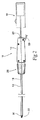
誘導管12の本質的に直線の構成において、誘導管12は、例えば、脈管内またはカニューレが挿入されたアクセス通路を通って、体内部位への配備のためにうまく方向づけされる。そのような配備中に、誘導管12は、従来の誘導ワイヤによって通過され得、該従来の誘導ワイヤは内部通路18を通って挿入され得る。あるいは、誘導管12は、内部誘導通路18を通って挿入され得る拡張器60(図1Aを参照されたい)と共に用いられ得る。拡張器60は、その遠位端に先細のノーズコーン62と、その近位端にルアー(Luer)タイプのコネクタ64と、ノーズコーン62をルアーコネクタ64に結合するシャフト66とを特徴にする。拡張器60は、望ましくは、拡張器の長さ全体に延びる誘導ワイヤルーメン68を含む。使用時、先細のノーズコーン62は、脈管内またはカニューレが挿入されたアクセス通路へのアクセスを容易にするために、操縦可能な誘導カテーテル10の遠位先端すなわち開口部22を通過して延び、誘導ワイヤに対する追跡の向上を提供する。
In the essentially straight configuration of the
誘導管12を所望の体の部位に配備(そして、誘導ワイヤおよび拡張器60が使用された場合は、誘導ワイヤおよび拡張器60を引き出し)次第、臨床医は、操縦アセンブリ24を操作し、誘導管12の曲がったまたは偏向された状態に誘導管12の遠位端部位を偏向させる。放射線不透過性マーカM(図3を参照されたい)が、遠位端部位に設置され、偏向された端部部位の向きの蛍光透視の視覚化を可能にし得る。遠位通路端22の曲がったまたは偏向された構成において、遠位通路端22は、体の部位における標的とする組織面との所望の関係に方向づけられ得る。
Upon deployment of the
望ましくは−−図5A、5B、および5Cが示すように−−、放射線不透過性マーカMは、部分的なリング(すなわち、Cの形状)または向きによって変化する同種の形状を形成し、その結果、放射線不透過性の画像は、異なる方向から観察されたとき視覚的に明瞭である。例えば、前向きでは上向きのU形(図5A)、または、後向きでは下向きのU形すなわち「小文字のN」形、または横向きでは縁上の形状(図5C)を示す。複数の放射線不透過性マーカも、様々な向きでの観察されるとき視覚的に明瞭である画像を提供するために用いられ得ることは理解されるべきである。 Desirably--as shown in FIGS. 5A, 5B, and 5C--the radiopaque marker M forms a partial ring (ie, the shape of C) or a similar shape that varies with orientation, As a result, radiopaque images are visually clear when viewed from different directions. For example, the U-shape pointing upwards (FIG. 5A) forward, or the U-shape facing downward or “lowercase N”, or the shape on the edge (FIG. 5C) laterally. It should be understood that a plurality of radiopaque markers can also be used to provide an image that is visually clear when viewed in various orientations.
望ましくは(図3が示すように)、誘導管12は、通路18を通って手術器具16が通過する前に、曲がったまたは偏向された構成にされる。図4が示すように、一旦誘導管12が曲がりまたは偏向された構成になると、手術器具16は、通路18を通って進められ、使用のために曲がった構成によって組織表面との所望の関係に誘導され得る。
Desirably (as FIG. 3 shows) the
操縦アセンブリ24は、誘導管12の偏向された状態に誘導管12の遠位端を保持し、それによって、使用時に手術器具16を所望の関係に維持する。操縦可能な誘導管12は、操縦機構を搭載する必要なく、または手術器具16に誘導ワイヤルーメンを装備する必要がない。
The steering
図3および図4が示すように、操縦アセンブリ24は、臨床医による片手の操作となるように構成されることが望ましい。操縦アセンブリ24はまた、臨床医の相対的に小さな増加を誘導管の偏向の相対的に大きな増加に転換するのに十分な機械的な有利性を提供するように構成されることが望ましい。
As shown in FIGS. 3 and 4, the steering
後により詳細に記述されるように、また図3が全体的に示すように、操縦アセンブリ24は、臨床医によって操作され得るアクチュエータ26を含む。アクチュエータ26は、リンケージシステム28によって、偏向コンポーネント30に結合され、偏向コンポーネントは、誘導管12の遠位端部位に結合される。
As will be described in more detail later, and as FIG. 3 generally shows, steering
全般的な操作において、臨床医によってアクチュエータ26に加えられる手動の力は、リンケージシステム28を介して偏向コンポーネント30に対して加えられる引く力すなわち張力に転換され、偏向コンポーネント30は、誘導管12の遠位端部位を偏向または曲げる。リンケージシステム30は、アクチュエータ26の動きの相対的に小さな増加を偏向コンポーネント30の動きの相対的により大きな増加に増幅する機械的な有利性をもって構成されることが望ましい。
In general operation, a manual force applied by the clinician to the
誘導管12および操縦アセンブリ24の特定の実施形態のさらなる詳細は、ここで記述される。
Further details of specific embodiments of the
A.誘導管のコンポーネント
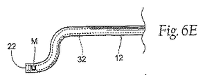
図6Aおよび図6Bを参照すると、例示された実施形態において、誘導管12は、記述済みの内部通路18の部分を構成するメインルーメン32を備えている。誘導管12は制御ルーメン34も含む。前に記述された偏向コンポーネント30は、制御ルーメン34を通って延びる。
A. Guide Tube Components Referring to FIGS. 6A and 6B, in the illustrated embodiment, the
例示された実施形態は、1つの制御ルーメン34および1つの偏向コンポーネント30を示す。所望に応じ、複数の制御ルーメン(および偏向コンポーネント)が提供され得ることは理解されるべきである。図6Dおよび図6Eに見られ得るように、複数の制御ルーメンは、操縦可能なガイド10の屈曲性のある誘導管12(例えば、遠位端部位)を2つ以上の方向に向ける能力を提供する。例えば、180度離れた方向に置かれた2つの制御ルーメン34、34’(2つの偏向コンポーネント30、30’と共に)は、遠位端部位が1つの平面内における2つの方向に90度偏向されることを可能にする。この特徴は、標的とする組織部位に対して遠位開口部22を正確に位置決めするさらなる操縦制御を可能にする。
The illustrated embodiment shows one
例示的な実施形態において、制御ルーメン34も、メインルーメン32の外に延びるように示される。制御ルーメン34がメインルーメン32の内部に延び得るか、またはメインルーメン32および制御ルーメン34が複合物として形成され得ることは理解されるべきである。
In the exemplary embodiment, the
メインルーメン32および制御ルーメン34の両方ともライナー36を含むのが望ましい。各ライナー36は、PTFEなどの低摩擦係数を有する物質を備えていることが好ましいが、同種の機械的な特性を有する他の物質が用いられ得る。ライナー36がメインルーメン32に存在することは、摩擦を減少させ、メインルーメン32を通る手術器具18の通過を容易にする。制御ルーメン34にライナー36が存在することは摩擦を減少させ、このことは、偏向コンポーネント30を操作するのに必要な引く力すなわち張力を低減する。
Both
誘導管12も補強シース(sheath)38を含むことが望ましい。補強シース38は、メインルーメン32および制御ルーメン34の両方を包む。補強シース38は、複数の形状構成を有し得、複数の物質から作られ得、複数のパターンで編成され得る。パターンは、単純なコイルから複合のブレイド編成まで及ぶ。パターンは、一様であり得、または、カテーテル管12の長さに沿って変動し得る。例示的な実施形態において、補強シース38は、例えば、ステンレス鋼、チタン、コバルト合金、ポリマーおよび天然ファイバから作られる丸いワイヤから作られるブレイド形状をしている。
Desirably, the
誘導管12も先端補強エレメント40を含むことが望ましい。補強エレメント40は、通路18の遠位開口部22に、またはその近くに配置され、偏向コンポーネント30における引っ張りの結果、偏向時のメインルーメン32の崩壊またはゆがみを阻止するように働く。
It is desirable that the
所望の実施形態において、(図6Bを参照されたい)、先端補強エレメント40は、均一リングなどの金属のリングを備えているが、他の形状および物質も考えられる。図6Aおよび図6Bに見られるように、先端補強エレメント40は、補強シース38の上に配置されるように示される。あるいは、先端補強エレメント40および補強シース38は、複合構造を備え得る。
In the desired embodiment (see FIG. 6B), the
所望の実施形態において、偏向コンポーネント30は、先端補強エレメント40の回りを完全に連続してループし、制御ルーメン34を通ってハンドル14に戻り、後により詳しく記述されるように、ハンドル14において、偏向コンポーネント30はリンケージシステム28に結合される。代替の実施形態において(図6Cを参照されたい)、偏向コンポーネント30は、補強エレメント41の一部分のみの回りをループする。示されるように、補強エレメント41は、少なくとも1つの結合エレメント43に一緒に結合された1つを超えるリング(すなわち、2つ以上の個別のリング)を備えている。この構成において、偏向コンポーネント30は、1つ以上の結合エレメント43の回りをループされ得る。
In the desired embodiment, the
誘導管12はまた、カバー42を含むことが望ましい。カバー42は、これまで記述された内部構造のすべてを包み、複合構造を形成する。カバー42は、誘導管12の全長にわたって、様々なタイプの物質または様々な物理的特性を有する均一の物質から作られ得る。カバー42は、均一な厚さであり得るか、または誘導管12の長さに沿って変動し得る。好ましい実施形態において、カバーは、異なる堅さのポリマー材料から作られる。最も柔らかい部分は、誘導管12の遠位部分(開口部22の近く)に位置し、より堅い部分は、誘導管12の近位部分(ハンドル14内)に位置する。カバー42はまた、カバー42が放射線不透過性にすることを可能にするポリマー内の材料、または摩擦を減少させる材料を含み得る。
The
先端補強エレメント40、41および/または補強シース38はまた、放射線不透過性マーカとして用いられ得る。代わりに、または組み合せて、1つ以上の放射線不透過性マーカMは、カテーテルアセンブリ12の遠位端に取り付けられ得る。放射線不透過性物質を使用することは、誘導管12の偏向された方向を測定することを可能にする。所定の放射線不透過性マーカは、プラチナから作られ得る。なおも、他の物質(および様々な形状)が用いられ得る。
The
図7が示すように、誘導管12は、ハンドル14の遠位端の中に延びる。移行シャフト44は、一方の端において誘導管12の近位端(ここはカバー42がより堅い)に接続され、他方の端においてハンドル14の最も近位の部位を占める密閉エレメント46に接続される。密閉エレメント46は、内部通路18の延長を備えている内部ルーメン48を含み、また近位開口部20を含む。移行シャフト44はまた、内部通路18の延長も形成する内部ルーメン50を含み、近位開口部20と連絡する誘導管12のメインルーメン32を連結する。移行シャフト44は、誘導管12との一体化コンポーネントであり得る。
As FIG. 7 shows, the
密閉エレメント46は、通路18の近位開口部20にあるかまたはその近くにあるインライン止血バルブアセンブリ52を含むことが望ましい。バルブアセンブリ52は、どの手術器具16も通路18に存在しないときだけでなく、手術器具16が通路18内にあるとき、近位開口部20を密閉することによって、血液または流体の損失を防ぐ。
The sealing
バルブアセンブリ52は、メイン密閉コンポーネント54およびリップ密閉コンポーネント56を含むことが望ましく、メイン密閉コンポーネント54およびリップ密閉コンポーネント56は、別個または一体化のコンポーネントを備え得る。メイン密閉コンポーネント54は、通路18に手術器具16がない場合に近位開口部20を密閉する。リップ密閉コンポーネント56は、近位開口部20を通って通路18の中に手術器具16が挿入され次第、密閉する。
The
注入バルブ58も、密閉エレメント46を介して通路18に結合され得る。このように、流体は、通路18を通って体内部位に運ばれ、例えば、使用時に通路18から材料を流す。
An
記述されるように、誘導管12は、ハンドル14に固定され、ハンドル14に対して回転しない。誘導管12を回転させるために、臨床医はハンドル14を回転させなければならない。
As described, the
B.操縦アセンブリのコンポーネント
1.アクチュエータ
操縦アセンブリ24のアクチュエータ26が、スライディングレバーまたはピストルグリップなどの多くの形状をとり得ることは理解されるべきである。アクチュエータ26は、近位端、遠位端または中間部分など、ハンドル14上の多くの場所に位置され得る。図1〜図4に示された実施形態において、アクチュエータ26は、ハンドル14の遠位端に回転するように取り付けられる縦溝付きノブの形状を取る。ノブ26は、それがハンドル14を保持する臨床医の手の親指によって回転し得るように位置を定められる。図3に示されるように、ハンドル14は手の平に保持され、ノブ26は親指によって操作される。
B. Steering assembly components Actuators It should be understood that the
例示された配置(図8および図9に最も良く示される)において、ノブ26は、前部および後部のスラスト軸受表面132および134を含む。これらのスラスト軸受表面は、ノブコンポーネントに一体化され得るか、完全なアセンブリとするためにノブ26に追加される別個のコンポーネントであり得る。ハンドル14の前部ジャーナル136および後部ジャーナル138はスラスト軸受表面132および134を支持し、その結果ノブ26は、親指の動きによってハンドル14の遠位端に対して容易に回転され得る。
In the illustrated arrangement (best shown in FIGS. 8 and 9), the
2.リンケージシステム
a.ラックアンドピニオンギアアセンブリ
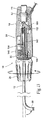
例示的な配置において、リンケージシステム28は、アクチュエータノブ26の旋回の動きを直線的な力の方向に転換する。この転換を行なうために(図8および図9を参照されたい)、リンケージシステム28は、ノブ26内に形成され、ノブ26と同様に回転するメスねじ切りされたシャフト140と、ハンドル14内のチャネル144において直線に動くように取り付けられるスライダ142に結合され、ねじ切りされたオスコンポーネント146とを含む。これらエレメントの両方へのねじ山の配置は逆にされ得ることは理解されるべきである。ねじ山は、任意の形状および/またはタイプをとり得、セルフロッキングまたはノンロッキングであり得る。好ましい配置において、メスねじ切りされたシャフト140およびオスねじ切りされたコンポーネント146上のねじ山は、ロッキングである。
2. Linkage system a. Rack and Pinion Gear Assembly In the exemplary arrangement, the
スライダ142は、チャネル144によってねじりまたは回転することが防止される。ねじ切りされたコンポーネント146は、チャネル144内でねじりまたは回転しないようにされるスライダ142に結合され、同様に回転しないようにされる。
The
ねじ切りされたオスコンポーネント146は、ノブ26の方向にスライダ142から延びる。コンポーネント146上のオスねじは、ノブ26の回転に応答してシャフト140のメスねじ溝にねじ込むように構成される。ノブ26の回転は、シャフト140内のねじ切りされたコンポーネント146を徐々に動かす。スライダ146は、追従し、ノブ26が回転する方向に従ってチャネル144内の直線の方向において、前方に(ハンドル14の遠位端に向かって)、または後方に(ハンドル14の近位端に向かって)移動する。チャネル144内のスライダ142の後方への直線の移動は、近位ストッパ148によって停止される。この位置(すなわち、スライダ142がストッパ148に対して接しているとき)(図8に示されるように)は、簡潔に言うと「中立位置」と呼ばれる。なぜなら、この位置においてリンケージシステム28は、偏向コンポーネント30に対して力を加えないように構成されるからである。
A threaded
中立の位置にあるとき(図8に示されるように)、オスコンポーネント146は、オスコンポーネント146の一部分をシャフト140の部分内にねじ込むのに十分な距離だけスライダ142から延びている。中立の位置にあるとき、1つの所定の方向へのノブ26の回転(例示された実施形態において、臨床医の視点から時計回り)(図11を参照されたい)は、シャフト140に沿ってコンポーネント146を前進させ、チャネル144内で直線的に前方に(すなわち、ノブ26に向かって)スライダ142を引っ張る。起動のための方向は、逆であり得る(すなわち、ノブ26を回転させることが直線的にノブ26から離れる方向にスライダ142を進ませる)ことは理解されるべきである。
When in the neutral position (as shown in FIG. 8), the
リンケージシステム28は、スライダ142のこの直線の前方への移動を偏向コンポーネント30に対する張力すなわち引く力に転換するように構成される。この転換を行うために、リンケージシステム28は、ラックアンドピニオンギアシステムを含む。より詳細には(図8および図9を参照されたい)、ラック150は、スライダ142と共通の直線移行するようにスライダ142に結合される。例示された実施形態において、ラック150は、ノブ26から離れる方向にハンドル14のより近位の部位に延びる。そこで、ラック150はピニオンギア152に係合する。ピニオンギア152は、メインギア154に結合され、メインギア154は、ハンドル14内のシャフトの回りに回転するように支持される。メインギア154は、同時に、別のピニオンギア158を介して、ピックアップリール56に結合され、ピックアップリール56は、同様に、ハンドル14内のシャフトの回りに回転するように支持される。偏向コンポーネント30の近位端は、ピックアップリール156に結合される。取り付けは、例えば、圧着、結束、または接着によって実施され得る。
The
所定の方向(例示される実施形態において、反時計回り)にピックアップリール156を回転することは、偏向コンポーネント30に対して直線的な後方への引く力すなわち張力を加え、それによって、カテーテル管12の遠位端部位を曲げる。
Rotating the
代替の配置(図示されていない)において、ノブに結合されたらせん切ギア(spiral cut gear)は、ラックに係合し、ノブの回転に応答して直線方向にラックを動かし得る。 In an alternative arrangement (not shown), a spiral cut gear coupled to the knob can engage the rack and move the rack in a linear direction in response to the rotation of the knob.
図11が最も良く示すように、リンケージシステム28は、記述されるように、ノブ26に向かってスライダ142を引っ張るノブ26の回転をラック150の直線の前方への動きの転換に転換する。ラック150の直線の前方への動きの転換は、同様に、ピニオンギア152の回転に転換される(例示された実施形態において時計回り)。ピニオンギア152の回転は、メインギア154の反対の回転(すなわち、反時計回り)に転換する。メインギア154の回転は、ピニオンギア158の反対の回転(すなわち、時計回り)に転換する。ピニオンギア158の回転は、ピックアップリール156の反対の回転(すなわち、反時計回り)に転換する。ピックアップリール156の回転は、同様に、偏向コンポーネント30に対する直線的に後方への引く力すなわち張力に転換され、誘導管12の遠位端を偏向する。
As best shown in FIG. 11,
メインギア154の直径だけでなく、ラック150とメインギアのギア比は、ハンドル14によって課されるサイズの制約を考慮して、所望の機械的な利点を提供するために選択される。機械的な利点は、ノブ26の回転の所定の増加に対して、偏向コンポーネント30の偏向の増加量を増幅する。機械的な利点により、ノブ26の回転に必要な手動の親指によって付加される力は、臨床医にとって、普通であり負担がない。誘導管14の偏向は、快適な親指制御によって行なわれる。
The gear ratio between the
b.ピボット張力システム
図12および図13は、操縦アセンブリ24のための代替の配置を示す。図12および図13に示される代替の配置は、図8に示される配置の機能的なコンポーネントの多くを共有する。両方とも、内部のメスねじ切りされたシャフト140を担持する回転式ノブ26と、ねじ切りされたオスコンポーネント146を、ねじ切りされたシャフト140にねじ係合するスライダ142とを含む。
b. Pivot Tension System FIGS. 12 and 13 show an alternative arrangement for the
また、前述のようにかつ図13に示されるように、アクチュエータノブ26の回転は、ハンドル14の内部のチャネル144内のスライダ142の直線的な動きに転換される。図11に示されるラックおよびピニオンリンケージ配置において、スライダ144への遠位への動き(ノブ26に向う)は、スライダ144に取り付けられたラック150の横の動きによって、テイクアップリール156に与えられた回転を介して、偏向コンポーネント30に張力を加えるように働く。図12および図13に示される代替の配置において、スライダ142の近位への移動(ノブ26から離れる)は、ハンドル14の長手方向軸に沿って近位方向に旋回するテンションアーム160を介して偏向コンポーネント30に張力を加える。偏向コンポーネント30は、旋回するテンションアーム160に取り付けられ、近位への旋回の動きの結果として張力がかけられ、図13が示すように、カテーテル管12の遠位部位を曲げる。
Also, as described above and shown in FIG. 13, the rotation of the
より詳細には、テンションアーム160は、ハウジング14内のピン162に取り付けられ、ノブ26の方向に遠位に傾く第1の旋回位置(図12を参照されたい)とノブ26から離れように近位に傾く第2の旋回位置(図13を参照されたい)との間で旋回する。第1の旋回位置において(図12)、テンションアーム160に取り付けられた偏向コンポーネント30に張力は加えられない。第2の旋回位置において(図13)、偏向コンポーネント30は、張力がかけられ、誘導管12の遠位端部位を曲げるかまたは偏向する。
More particularly, the
第1の旋回位置にあるとき(図12)、旋回テンションアーム160はスライダ142の近位端に対して静止している。ノブ26が所定の方向に回転されると(例示された実施形態において(図13)、臨床医の観点から反時計回りに)、スライダ142は、ノブ26から直線的に離れる方向に動かされる。スライダ142はテンションアーム160を押し、テンションアーム160をピン162回りに旋回させ、第2の旋回位置にする。テンションエレメントの旋回は、偏向コンポーネント30に対する直線的な近位への引く力すなわち張力に換わり、誘導管12の遠位端を偏向させる。
When in the first pivot position (FIG. 12), the
スライダ142の直線の動きを旋回テンションアーム160の回転の動きに転換することは、全体システムの機械的な力の有利性を減少させるが、回転制御エレメントの所定の回転当りの遠位端部位の偏向量を増加させる。
Converting the linear movement of the
3.偏向コンポーネント
偏向コンポーネント30は、ピックアップリール156または旋回テンションアーム160から、誘導管12の制御ルーメン34の中に延びる。偏向コンポーネント30は、強固で屈曲性のある材料、例えば、金属ワイヤ、ブレイド金属ワイヤ、モノフィラメントワイヤなどを備えていることが望ましい。好ましい配置において、偏向エレメント30は、連続した長さのブレイドポリマーまたは天然ファイバを備えている。図6Bが最も良く示すように、ファイバは、ピックアップリール156または旋回テンションアーム160から延び、制御ルーメン34を通って、先端補強エレメント40の回りを完全にループする。そこから、ファイバは、制御ルーメン34を通って戻るように延び、ピックアップリール156または旋回テンションアーム160において終端する。
3. Deflection
この配置において、偏向コンポーネント30は、様々な方法によって先端補強エレメント40に取り付けられ得る。様々な方法は、接着、溶接技術、はんだ技術、偏向コンポーネント30を結束または巻きつけるなどの方法、または偏向コンポーネント30および先端補強エレメント40を複合構造として形成することなどによることである。図6Cに示される代替の実施形態において、別の取り付け手段は、偏向コンポーネント30を先端補強エレメント41に接続することが必要ではない場合がある。
II.操縦可能な誘導デバイスの使用法
図14は、手術器具16を組織部位に誘導する使用中の操縦可能な誘導デバイス10を示す。図14において、手術器具16は、らせん形ファスナー164を利用する動力デバイスの形式を取る。使用時にらせん形ファスナーを利用する脈管内デバイスの代表的な実施形態は、米国特許出願第10/786,465号、名称「Systems and Methods for Attaching a Prosthesis Within a Body Lumen or Hollow Organ」に記述され、該特許出願は、本明細書に参考として援用される。使用時(図14に示すように)、脈管内ファスナーデバイス16は、1つ以上のファスナーを補てつ166に適用するために誘導デバイス10を介して操作され、補てつ166は、例えば、心臓と腸骨の分岐との間の部位における大動脈の動脈瘤を修復するために、空洞の身体器官および/または血管の病気のおよび/または損傷した切片を修復するために配備される。
In this arrangement, the
II. Using Steerable Guidance Device FIG. 14 shows the
使用時、操縦可能な誘導デバイス10は、従来の脈管内アプローチによって標的とする組織部位に導入される。例えば、標的とする組織部位が大動脈にあるとき、誘導デバイス10は、大腿部の動脈を通って導入され得る。しかしながら、他のアクセス部位および方法が利用され得る。誘導デバイス10は、通路18を通って延びる誘導ワイヤの上に導入されることが望ましい。誘導ワイヤは、別に配備された補てつ導入器具によって、補てつ166がその上に以前に導入された誘導ワイヤと同じものを備え得る。あるいは代わりに、操縦可能な誘導デバイス10の導入は、別のアクセス部位を通って実施され得る。
In use, the
誘導ワイヤ上の補てつ導入器具の引き抜き次第、蛍光透視の視覚化の下で、臨床医は、同じ誘導ワイヤ上の誘導デバイス10および拡張器60を追跡し、補てつに対して所望の位置にまたはその近くに、デバイス10の遠位端部位を位置させる。誘導ワイヤおよび拡張器60は、このとき引き抜かされ得る。操縦アセンブリ24を起動して(ノブ26を回転させ)、なおも蛍光透視の視覚化を用いながら、臨床医は、デバイス10の遠位端部位を偏向し――および必要に応じて、ハンドル14を回転させ、カテーテル管12を回転させる――、ファスナー164の導入が所望される部位に対する所望の向きの関係に通路18の遠位開口部22を方向づける。
Upon withdrawal of the prosthetic introducer on the guide wire, under fluoroscopy visualization, the clinician tracks the
図14が示すように、手術器具16、例えば、脈管内ファスナーデバイスは、このとき近位開口部20を通って挿入され、ファスナー164がこのとき方向づけされた遠位開口部22の外に配備されるように位置するまで、通路18を通って進められる。手術器具16はファスナー164を補てつ166に当てるように動作され得る。手術器具16が単発の発射デバイスである場合、すなわち、手術器具が1つのみのファスナー164を携行している場合、手術器具16は通路18を通って引き抜かれ、新しいファスナー164が取り付けられる。デバイス10の遠位端部位は、新しい固定部位に対面する関係に再方向づけされる。手術器具16は、通路18を通って戻され、挿入され、第2のファスナーを新しい固定部位に当てる。この順序は、所望の数および配列のファスナー164が補てつ166に当てられるまで、反復される。この時点で、誘導デバイス10は引き抜かれ得る。
As FIG. 14 shows, a
前述のことは、本発明の原理を例示することのみとしてみなされる。さらに、多くの修正および変更が当業者に容易に思いつくので、示されかつ記述されたまさにその構造および動作に本発明を限定することは所望されない。好ましい実施形態が記述されたが、詳細は本発明から逸脱することなく変更され得、本発明は特許請求の範囲によって定義される。 The foregoing is considered as illustrative only of the principles of the invention. Further, since many modifications and changes will readily occur to those skilled in the art, it is not desired to limit the invention to the exact construction and operation shown and described. While preferred embodiments have been described, the details may be changed without departing from the invention, which is defined by the claims.
Claims (10)
操縦アセンブリであって、該操縦アセンブリは、遠位端部位を曲げるための偏向させる力を加えるために該誘導管の該遠位端部位に結合された偏向エレメントと、アクチュエータと、該アクチュエータの動作に応答して該偏向させる力を加えるために該偏向エレメントに該アクチュエータを結合するリンケージシステムとを備え、該リンケージシステムは、ラックと該ラックに結合されたギアトレインとを含み、該リンケージシステムは、該偏向させる力を該偏向コンポーネントに加えるために、該アクチュエータの回転を該ラックの直線の動き、そして該ギアトレインの回転に転換するように動作可能である、操縦アセンブリと
を備えている、誘導デバイス。 A guide tube defining a guide passage, wherein the surgical instrument can be deployed through the guide passage to a body site;
A steering assembly comprising a deflection element coupled to the distal end portion of the guide tube to apply a deflecting force to bend the distal end portion, an actuator, and an operation of the actuator A linkage system that couples the actuator to the deflecting element to apply the deflecting force in response to the linkage, the linkage system including a rack and a gear train coupled to the rack, the linkage system comprising: A steering assembly operable to convert rotation of the actuator into linear movement of the rack and rotation of the gear train in order to apply the deflecting force to the deflection component; Induction device.
1つ以上のファスナーを組織に当てる手術器具と
を備えている、システム。 An inductive device according to claim 1;
And a surgical instrument for applying one or more fasteners to the tissue.
該誘導デバイスを内部の組織部位に配備することと、
前記誘導管の前記遠位端部位を曲げるために前記操縦アセンブリを操作することと
を包含する、方法。 Providing an inductive device according to claim 1;
Deploying the guidance device to an internal tissue site;
Manipulating the steering assembly to bend the distal end portion of the guide tube.
前記誘導デバイスを内部の組織部位に配備することと、
前記誘導管の前記遠位端部位を曲げるために前記操縦アセンブリを操作することと、
該誘導デバイス中を経て前記手術器具を通すことと、
少なくとも1つのファスナーを組織に当てるために、該誘導デバイスの中にある間に、該手術器具を操作することと
を包含する、方法。 Providing a system according to claim 3;
Deploying the guidance device to an internal tissue site;
Manipulating the steering assembly to bend the distal end portion of the guide tube;
Passing the surgical instrument through the guide device;
Manipulating the surgical instrument while in the guidance device to apply at least one fastener to tissue.
操縦アセンブリであって、該操縦アセンブリは、遠位端部位を曲げるための偏向させる力を加えるために該誘導管の該遠位端部位に結合された偏向エレメントと、アクチュエータと、該アクチュエータの動作に応答して該偏向させる力を加えるために該偏向エレメントに該アクチュエータを結合するリンケージシステムとを備え、該リンケージシステムは、スライダと該スライダに結合された旋回レバーアームとを含み、該リンケージシステムは、該偏向させる力を該偏向コンポーネントに加えるために、該アクチュエータの回転を該スライダの直線の動きに、そしておよび該レバーアームの旋回の動きに転換するように動作可能である、操縦アセンブリと
を備えている、誘導デバイス。 A guide tube defining a guide passage, wherein the surgical instrument can be deployed through the guide passage to a body site;
A steering assembly comprising a deflection element coupled to the distal end portion of the guide tube to apply a deflecting force to bend the distal end portion, an actuator, and an operation of the actuator A linkage system that couples the actuator to the deflection element to apply the deflecting force in response to the linkage system, the linkage system including a slider and a pivot lever arm coupled to the slider, the linkage system A steering assembly operable to convert the rotation of the actuator into a linear movement of the slider and to a pivoting movement of the lever arm to apply the deflecting force to the deflecting component; Inductive device equipped with.
1つ以上のファスナーを組織に当てる手術器具と
を備えている、システム。 An inductive device according to claim 6;
And a surgical instrument for applying one or more fasteners to the tissue.
該誘導デバイスを内部の組織部位に配備することと、
前記誘導管の前記遠位端部位を曲げるために前記操縦アセンブリを操作することと、
を包含する、方法。 Providing an inductive device according to claim 6;
Deploying the guidance device to an internal tissue site;
Manipulating the steering assembly to bend the distal end portion of the guide tube;
Including the method.
前記誘導デバイスを内部の組織部位に配備することと、
前記誘導管の前記遠位端部位を曲げるために前記操縦アセンブリを操作することと、
該誘導デバイス中を経て前記手術器具を通すことと、
少なくとも1つのファスナーを組織に当てるために、該誘導デバイスの中にある間に、該手術器具を操作することと
を包含する、方法。 Providing a system according to claim 8;
Deploying the guidance device to an internal tissue site;
Manipulating the steering assembly to bend the distal end portion of the guide tube;
Passing the surgical instrument through the guide device;
Manipulating the surgical instrument while in the guidance device to apply at least one fastener to tissue.
Applications Claiming Priority (2)
| Application Number | Priority Date | Filing Date | Title |
|---|---|---|---|
| US11/254,619 US9320503B2 (en) | 2001-11-28 | 2005-10-20 | Devices, system, and methods for guiding an operative tool into an interior body region |
| PCT/US2006/033741 WO2007046953A2 (en) | 2005-10-20 | 2006-08-29 | Devices, system, and methods for guiding an operative tool into an interior body region |
Publications (2)
| Publication Number | Publication Date |
|---|---|
| JP2009512497A true JP2009512497A (en) | 2009-03-26 |
| JP2009512497A5 JP2009512497A5 (en) | 2009-08-20 |
Family
ID=37962965
Family Applications (1)
| Application Number | Title | Priority Date | Filing Date |
|---|---|---|---|
| JP2008536574A Ceased JP2009512497A (en) | 2005-10-20 | 2006-08-29 | Device, system and method for guiding a surgical instrument to a body site |
Country Status (7)
| Country | Link |
|---|---|
| US (4) | US9320503B2 (en) |
| EP (1) | EP1937198B1 (en) |
| JP (1) | JP2009512497A (en) |
| CN (1) | CN101267788B (en) |
| AU (1) | AU2006305688B2 (en) |
| CA (1) | CA2625082A1 (en) |
| WO (1) | WO2007046953A2 (en) |
Cited By (17)
| Publication number | Priority date | Publication date | Assignee | Title |
|---|---|---|---|---|
| JP2013138864A (en) * | 2011-12-30 | 2013-07-18 | Biosense Webster (Israel) Ltd | Medical device control handle with multiple puller wires |
| US8685044B2 (en) | 2001-11-28 | 2014-04-01 | Aptus Endosystems, Inc. | Systems and methods for attaching a prosthesis with a body lumen or hollow organ |
| US8690897B2 (en) | 2001-11-28 | 2014-04-08 | Aptus Endosystems, Inc. | Devices, systems, and methods for prosthesis delivery and implantation, including the use of a fastener tool |
| US9023065B2 (en) | 2001-11-28 | 2015-05-05 | Aptus Endosystems, Inc. | Devices, systems, and methods for supporting tissue and/or structures within a hollow body organ |
| US9320503B2 (en) | 2001-11-28 | 2016-04-26 | Medtronic Vascular, Inc. | Devices, system, and methods for guiding an operative tool into an interior body region |
| US9320589B2 (en) | 2001-11-28 | 2016-04-26 | Medtronic Vascular, Inc. | Endovascular aneurysm repair system |
| WO2016147465A1 (en) * | 2015-03-17 | 2016-09-22 | 日本ライフライン株式会社 | Handle for medical device, and medical device |
| JP2016536090A (en) * | 2013-09-17 | 2016-11-24 | エシコン・エンド−サージェリィ・エルエルシーEthicon Endo−Surgery, LLC | Joint motion features of ultrasonic surgical instruments |
| JP2018506333A (en) * | 2015-01-21 | 2018-03-08 | メドトロニック ヴァスキュラー インコーポレイテッド | Guide catheter with operating mechanism |
| US9968353B2 (en) | 2001-06-04 | 2018-05-15 | Medtronic Vascular, Inc. | Catheter based fastener implantation apparatus and methods |
| JP2018099529A (en) * | 2013-04-30 | 2018-06-28 | セント・ジュード・メディカル・インターナショナル・ホールディング・エスエーアールエルSt. Jude Medical International Holding S.a,r.l. | Control handles for catheter |
| US10098770B2 (en) | 2001-11-28 | 2018-10-16 | Medtronic Vascular, Inc. | Endovascular aneurysm devices, systems, and methods |
| US10194905B2 (en) | 2001-11-28 | 2019-02-05 | Medtronic Vascular, Inc. | Devices, systems, and methods for endovascular staple and/or prosthesis delivery and implantation |
| CN109803712A (en) * | 2017-04-06 | 2019-05-24 | 朝日英达科株式会社 | Tubular body and conduit with the tubular body |
| JP2021521965A (en) * | 2018-04-26 | 2021-08-30 | ボストン サイエンティフィック サイムド,インコーポレイテッドBoston Scientific Scimed,Inc. | Electric telescope medical device delivery system |
| US11471650B2 (en) | 2019-09-20 | 2022-10-18 | Biosense Webster (Israel) Ltd. | Mechanism for manipulating a puller wire |
| US11964115B2 (en) | 2022-10-17 | 2024-04-23 | Biosense Webster (Israel) Ltd. | Mechanism for manipulating a puller wire |
Families Citing this family (273)
| Publication number | Priority date | Publication date | Assignee | Title |
|---|---|---|---|---|
| US20110087320A1 (en) * | 2001-11-28 | 2011-04-14 | Aptus Endosystems, Inc. | Devices, Systems, and Methods for Prosthesis Delivery and Implantation, Including a Prosthesis Assembly |
| US7147657B2 (en) * | 2003-10-23 | 2006-12-12 | Aptus Endosystems, Inc. | Prosthesis delivery systems and methods |
| US20090112302A1 (en) | 2001-11-28 | 2009-04-30 | Josh Stafford | Devices, systems, and methods for endovascular staple and/or prosthesis delivery and implantation |
| US20070084897A1 (en) | 2003-05-20 | 2007-04-19 | Shelton Frederick E Iv | Articulating surgical stapling instrument incorporating a two-piece e-beam firing mechanism |
| US9060770B2 (en) | 2003-05-20 | 2015-06-23 | Ethicon Endo-Surgery, Inc. | Robotically-driven surgical instrument with E-beam driver |
| US11896225B2 (en) | 2004-07-28 | 2024-02-13 | Cilag Gmbh International | Staple cartridge comprising a pan |
| US10159482B2 (en) | 2005-08-31 | 2018-12-25 | Ethicon Llc | Fastener cartridge assembly comprising a fixed anvil and different staple heights |
| US11484312B2 (en) | 2005-08-31 | 2022-11-01 | Cilag Gmbh International | Staple cartridge comprising a staple driver arrangement |
| US7934630B2 (en) | 2005-08-31 | 2011-05-03 | Ethicon Endo-Surgery, Inc. | Staple cartridges for forming staples having differing formed staple heights |
| US11246590B2 (en) | 2005-08-31 | 2022-02-15 | Cilag Gmbh International | Staple cartridge including staple drivers having different unfired heights |
| US7669746B2 (en) | 2005-08-31 | 2010-03-02 | Ethicon Endo-Surgery, Inc. | Staple cartridges for forming staples having differing formed staple heights |
| US20070106317A1 (en) | 2005-11-09 | 2007-05-10 | Shelton Frederick E Iv | Hydraulically and electrically actuated articulation joints for surgical instruments |
| US8186555B2 (en) | 2006-01-31 | 2012-05-29 | Ethicon Endo-Surgery, Inc. | Motor-driven surgical cutting and fastening instrument with mechanical closure system |
| US7845537B2 (en) | 2006-01-31 | 2010-12-07 | Ethicon Endo-Surgery, Inc. | Surgical instrument having recording capabilities |
| US8820603B2 (en) | 2006-01-31 | 2014-09-02 | Ethicon Endo-Surgery, Inc. | Accessing data stored in a memory of a surgical instrument |
| US20110290856A1 (en) | 2006-01-31 | 2011-12-01 | Ethicon Endo-Surgery, Inc. | Robotically-controlled surgical instrument with force-feedback capabilities |
| US20120292367A1 (en) | 2006-01-31 | 2012-11-22 | Ethicon Endo-Surgery, Inc. | Robotically-controlled end effector |
| US11793518B2 (en) | 2006-01-31 | 2023-10-24 | Cilag Gmbh International | Powered surgical instruments with firing system lockout arrangements |
| US8708213B2 (en) | 2006-01-31 | 2014-04-29 | Ethicon Endo-Surgery, Inc. | Surgical instrument having a feedback system |
| US8992422B2 (en) | 2006-03-23 | 2015-03-31 | Ethicon Endo-Surgery, Inc. | Robotically-controlled endoscopic accessory channel |
| US8029531B2 (en) * | 2006-07-11 | 2011-10-04 | Cambridge Endoscopic Devices, Inc. | Surgical instrument |
| US10568652B2 (en) | 2006-09-29 | 2020-02-25 | Ethicon Llc | Surgical staples having attached drivers of different heights and stapling instruments for deploying the same |
| US9017345B2 (en) * | 2006-10-06 | 2015-04-28 | Covidien Lp | Coil fastener applier with flexible shaft |
| US8684253B2 (en) | 2007-01-10 | 2014-04-01 | Ethicon Endo-Surgery, Inc. | Surgical instrument with wireless communication between a control unit of a robotic system and remote sensor |
| US8540128B2 (en) | 2007-01-11 | 2013-09-24 | Ethicon Endo-Surgery, Inc. | Surgical stapling device with a curved end effector |
| US11564682B2 (en) | 2007-06-04 | 2023-01-31 | Cilag Gmbh International | Surgical stapler device |
| US8931682B2 (en) | 2007-06-04 | 2015-01-13 | Ethicon Endo-Surgery, Inc. | Robotically-controlled shaft based rotary drive systems for surgical instruments |
| US11849941B2 (en) | 2007-06-29 | 2023-12-26 | Cilag Gmbh International | Staple cartridge having staple cavities extending at a transverse angle relative to a longitudinal cartridge axis |
| US7819298B2 (en) | 2008-02-14 | 2010-10-26 | Ethicon Endo-Surgery, Inc. | Surgical stapling apparatus with control features operable with one hand |
| US7866527B2 (en) | 2008-02-14 | 2011-01-11 | Ethicon Endo-Surgery, Inc. | Surgical stapling apparatus with interlockable firing system |
| RU2493788C2 (en) | 2008-02-14 | 2013-09-27 | Этикон Эндо-Серджери, Инк. | Surgical cutting and fixing instrument, which has radio-frequency electrodes |
| US9179912B2 (en) | 2008-02-14 | 2015-11-10 | Ethicon Endo-Surgery, Inc. | Robotically-controlled motorized surgical cutting and fastening instrument |
| US8636736B2 (en) | 2008-02-14 | 2014-01-28 | Ethicon Endo-Surgery, Inc. | Motorized surgical cutting and fastening instrument |
| DE102008012113A1 (en) * | 2008-03-02 | 2009-09-03 | Transcatheter Technologies Gmbh | Implant e.g. heart-valve-carrying stent, for e.g. arresting blood vessel, has fiber by which section of implant is reducible according to increasing of implant at extended diameter by unfolding or expansion of diameter with expansion unit |
| US9005230B2 (en) | 2008-09-23 | 2015-04-14 | Ethicon Endo-Surgery, Inc. | Motorized surgical instrument |
| US8210411B2 (en) | 2008-09-23 | 2012-07-03 | Ethicon Endo-Surgery, Inc. | Motor-driven surgical cutting instrument |
| US11648005B2 (en) | 2008-09-23 | 2023-05-16 | Cilag Gmbh International | Robotically-controlled motorized surgical instrument with an end effector |
| US9386983B2 (en) | 2008-09-23 | 2016-07-12 | Ethicon Endo-Surgery, Llc | Robotically-controlled motorized surgical instrument |
| US8608045B2 (en) | 2008-10-10 | 2013-12-17 | Ethicon Endo-Sugery, Inc. | Powered surgical cutting and stapling apparatus with manually retractable firing system |
| US8419623B2 (en) * | 2009-01-28 | 2013-04-16 | Cani Optical Systems, Llc | Portable endoscope for diverse medical disciplines |
| US7918376B1 (en) * | 2009-03-09 | 2011-04-05 | Cardica, Inc. | Articulated surgical instrument |
| US20100270354A1 (en) * | 2009-04-22 | 2010-10-28 | Ofir Rimer | Ergonomic rotary tacker |
| WO2011041069A1 (en) * | 2009-09-30 | 2011-04-07 | Boston Scientific Scimed, Inc. | Ligating band dispenser device |
| EP2559402B1 (en) * | 2009-12-01 | 2016-05-04 | Altura Medical, Inc. | Modular endograft devices |
| EP2520130B1 (en) | 2009-12-31 | 2020-12-09 | Nokia Technologies Oy | Method and apparatus for performing multiple forms of communications in one session |
| US20110288533A1 (en) * | 2010-05-20 | 2011-11-24 | Bipore Medical Devices, Inc. | Tip Controllable Guidewire Device |
| US9861361B2 (en) | 2010-09-30 | 2018-01-09 | Ethicon Llc | Releasable tissue thickness compensator and fastener cartridge having the same |
| US10945731B2 (en) | 2010-09-30 | 2021-03-16 | Ethicon Llc | Tissue thickness compensator comprising controlled release and expansion |
| US9629814B2 (en) | 2010-09-30 | 2017-04-25 | Ethicon Endo-Surgery, Llc | Tissue thickness compensator configured to redistribute compressive forces |
| US9320523B2 (en) | 2012-03-28 | 2016-04-26 | Ethicon Endo-Surgery, Llc | Tissue thickness compensator comprising tissue ingrowth features |
| US11925354B2 (en) | 2010-09-30 | 2024-03-12 | Cilag Gmbh International | Staple cartridge comprising staples positioned within a compressible portion thereof |
| US9295464B2 (en) | 2010-09-30 | 2016-03-29 | Ethicon Endo-Surgery, Inc. | Surgical stapler anvil comprising a plurality of forming pockets |
| US9839420B2 (en) | 2010-09-30 | 2017-12-12 | Ethicon Llc | Tissue thickness compensator comprising at least one medicament |
| US11812965B2 (en) | 2010-09-30 | 2023-11-14 | Cilag Gmbh International | Layer of material for a surgical end effector |
| US8695866B2 (en) | 2010-10-01 | 2014-04-15 | Ethicon Endo-Surgery, Inc. | Surgical instrument having a power control circuit |
| US9775982B2 (en) | 2010-12-29 | 2017-10-03 | Medtronic, Inc. | Implantable medical device fixation |
| US10112045B2 (en) | 2010-12-29 | 2018-10-30 | Medtronic, Inc. | Implantable medical device fixation |
| US9585672B2 (en) | 2011-02-25 | 2017-03-07 | Thd S.P.A. | Device for implanting a prosthesis in a tissue |
| IT1405424B1 (en) * | 2011-02-25 | 2014-01-10 | Thd Spa | DEVICE FOR IMPLANTING A PROSTHESIS IN A FABRIC |
| RU2606493C2 (en) | 2011-04-29 | 2017-01-10 | Этикон Эндо-Серджери, Инк. | Staple cartridge, containing staples, located inside its compressible part |
| US9072535B2 (en) | 2011-05-27 | 2015-07-07 | Ethicon Endo-Surgery, Inc. | Surgical stapling instruments with rotatable staple deployment arrangements |
| US9119639B2 (en) | 2011-08-09 | 2015-09-01 | DePuy Synthes Products, Inc. | Articulated cavity creator |
| US9757538B2 (en) | 2011-12-15 | 2017-09-12 | Imricor Medical Systems, Inc. | MRI compatible control handle for steerable sheath with audible, tactile and/or visual means |
| US9821143B2 (en) * | 2011-12-15 | 2017-11-21 | Imricor Medical Systems, Inc. | Steerable sheath including elastomeric member |
| US20140135745A1 (en) | 2011-12-15 | 2014-05-15 | Imricor Medical Systems, Inc. | Mri compatible handle and steerable sheath |
| US10485435B2 (en) | 2012-03-26 | 2019-11-26 | Medtronic, Inc. | Pass-through implantable medical device delivery catheter with removeable distal tip |
| US9220906B2 (en) * | 2012-03-26 | 2015-12-29 | Medtronic, Inc. | Tethered implantable medical device deployment |
| US9854982B2 (en) | 2012-03-26 | 2018-01-02 | Medtronic, Inc. | Implantable medical device deployment within a vessel |
| US9339197B2 (en) | 2012-03-26 | 2016-05-17 | Medtronic, Inc. | Intravascular implantable medical device introduction |
| US9833625B2 (en) | 2012-03-26 | 2017-12-05 | Medtronic, Inc. | Implantable medical device delivery with inner and outer sheaths |
| US9717421B2 (en) | 2012-03-26 | 2017-08-01 | Medtronic, Inc. | Implantable medical device delivery catheter with tether |
| CN104334098B (en) | 2012-03-28 | 2017-03-22 | 伊西康内外科公司 | Tissue thickness compensator comprising capsules defining a low pressure environment |
| CN104321024B (en) | 2012-03-28 | 2017-05-24 | 伊西康内外科公司 | Tissue thickness compensator comprising a plurality of layers |
| US9101358B2 (en) | 2012-06-15 | 2015-08-11 | Ethicon Endo-Surgery, Inc. | Articulatable surgical instrument comprising a firing drive |
| US9649111B2 (en) | 2012-06-28 | 2017-05-16 | Ethicon Endo-Surgery, Llc | Replaceable clip cartridge for a clip applier |
| BR112014032776B1 (en) | 2012-06-28 | 2021-09-08 | Ethicon Endo-Surgery, Inc | SURGICAL INSTRUMENT SYSTEM AND SURGICAL KIT FOR USE WITH A SURGICAL INSTRUMENT SYSTEM |
| US9408606B2 (en) | 2012-06-28 | 2016-08-09 | Ethicon Endo-Surgery, Llc | Robotically powered surgical device with manually-actuatable reversing system |
| US20140001231A1 (en) | 2012-06-28 | 2014-01-02 | Ethicon Endo-Surgery, Inc. | Firing system lockout arrangements for surgical instruments |
| US9289256B2 (en) | 2012-06-28 | 2016-03-22 | Ethicon Endo-Surgery, Llc | Surgical end effectors having angled tissue-contacting surfaces |
| EP2882381B1 (en) | 2012-08-10 | 2018-12-26 | Lombard Medical Limited | Stent delivery system |
| WO2014109775A1 (en) * | 2013-01-14 | 2014-07-17 | Empire Technology Development, Llc | Trans-urethral sling delivery device |
| US9439693B2 (en) | 2013-02-01 | 2016-09-13 | DePuy Synthes Products, Inc. | Steerable needle assembly for use in vertebral body augmentation |
| RU2672520C2 (en) | 2013-03-01 | 2018-11-15 | Этикон Эндо-Серджери, Инк. | Hingedly turnable surgical instruments with conducting ways for signal transfer |
| US9737426B2 (en) | 2013-03-15 | 2017-08-22 | Altura Medical, Inc. | Endograft device delivery systems and associated methods |
| BR112015026109B1 (en) | 2013-04-16 | 2022-02-22 | Ethicon Endo-Surgery, Inc | surgical instrument |
| US9867612B2 (en) | 2013-04-16 | 2018-01-16 | Ethicon Llc | Powered surgical stapler |
| US10368911B2 (en) * | 2013-08-07 | 2019-08-06 | Baylis Medical Company Inc. | Methods and devices for puncturing tissue |
| JP6330045B2 (en) * | 2013-08-09 | 2018-05-23 | ボストン サイエンティフィック サイムド,インコーポレイテッドBoston Scientific Scimed,Inc. | Stent with radiopaque connector and method of manufacturing the same |
| US9675343B2 (en) * | 2013-08-12 | 2017-06-13 | Boston Scientific Scimed, Inc. | Wire coil tissue fixation device |
| ES2666373T3 (en) | 2013-08-16 | 2018-05-04 | Cardiac Pacemakers, Inc. | Management devices for wireless heart devices |
| US9510828B2 (en) | 2013-08-23 | 2016-12-06 | Ethicon Endo-Surgery, Llc | Conductor arrangements for electrically powered surgical instruments with rotatable end effectors |
| JP6338676B2 (en) * | 2013-09-30 | 2018-06-06 | セント・ジュード・メディカル,カーディオロジー・ディヴィジョン,インコーポレイテッド | Catheter with active linear return mechanism |
| CN103706017B (en) * | 2013-12-27 | 2016-08-17 | 先健科技(深圳)有限公司 | adjustable bending sheath tube |
| US10013049B2 (en) | 2014-03-26 | 2018-07-03 | Ethicon Llc | Power management through sleep options of segmented circuit and wake up control |
| CN106456176B (en) | 2014-04-16 | 2019-06-28 | 伊西康内外科有限责任公司 | Fastener cartridge including the extension with various configuration |
| BR112016023825B1 (en) | 2014-04-16 | 2022-08-02 | Ethicon Endo-Surgery, Llc | STAPLE CARTRIDGE FOR USE WITH A SURGICAL STAPLER AND STAPLE CARTRIDGE FOR USE WITH A SURGICAL INSTRUMENT |
| US20150297223A1 (en) | 2014-04-16 | 2015-10-22 | Ethicon Endo-Surgery, Inc. | Fastener cartridges including extensions having different configurations |
| BR112016023807B1 (en) | 2014-04-16 | 2022-07-12 | Ethicon Endo-Surgery, Llc | CARTRIDGE SET OF FASTENERS FOR USE WITH A SURGICAL INSTRUMENT |
| BR112017004361B1 (en) | 2014-09-05 | 2023-04-11 | Ethicon Llc | ELECTRONIC SYSTEM FOR A SURGICAL INSTRUMENT |
| US9788836B2 (en) | 2014-09-05 | 2017-10-17 | Ethicon Llc | Multiple motor control for powered medical device |
| US9700699B2 (en) | 2014-09-12 | 2017-07-11 | Freudenberg Medical, Llc | Modular handle assembly for a steerable catheter |
| US9737688B2 (en) | 2014-09-12 | 2017-08-22 | Freudenberg Medical, Llc | Modular handle assembly for a steerable catheter |
| US11523821B2 (en) | 2014-09-26 | 2022-12-13 | Cilag Gmbh International | Method for creating a flexible staple line |
| US10576249B2 (en) * | 2014-09-30 | 2020-03-03 | St. Jude Medical Cardiology Division, Inc. | Medical device including an actuator restraining assembly |
| US9924944B2 (en) | 2014-10-16 | 2018-03-27 | Ethicon Llc | Staple cartridge comprising an adjunct material |
| US10517594B2 (en) | 2014-10-29 | 2019-12-31 | Ethicon Llc | Cartridge assemblies for surgical staplers |
| US11141153B2 (en) | 2014-10-29 | 2021-10-12 | Cilag Gmbh International | Staple cartridges comprising driver arrangements |
| US9844375B2 (en) | 2014-12-18 | 2017-12-19 | Ethicon Llc | Drive arrangements for articulatable surgical instruments |
| BR112017012996B1 (en) | 2014-12-18 | 2022-11-08 | Ethicon Llc | SURGICAL INSTRUMENT WITH AN ANvil WHICH IS SELECTIVELY MOVABLE ABOUT AN IMMOVABLE GEOMETRIC AXIS DIFFERENT FROM A STAPLE CARTRIDGE |
| US10004501B2 (en) | 2014-12-18 | 2018-06-26 | Ethicon Llc | Surgical instruments with improved closure arrangements |
| US9987000B2 (en) | 2014-12-18 | 2018-06-05 | Ethicon Llc | Surgical instrument assembly comprising a flexible articulation system |
| US9844374B2 (en) | 2014-12-18 | 2017-12-19 | Ethicon Llc | Surgical instrument systems comprising an articulatable end effector and means for adjusting the firing stroke of a firing member |
| US10085748B2 (en) | 2014-12-18 | 2018-10-02 | Ethicon Llc | Locking arrangements for detachable shaft assemblies with articulatable surgical end effectors |
| US11154301B2 (en) | 2015-02-27 | 2021-10-26 | Cilag Gmbh International | Modular stapling assembly |
| US10441279B2 (en) | 2015-03-06 | 2019-10-15 | Ethicon Llc | Multiple level thresholds to modify operation of powered surgical instruments |
| US9993248B2 (en) | 2015-03-06 | 2018-06-12 | Ethicon Endo-Surgery, Llc | Smart sensors with local signal processing |
| JP2020121162A (en) | 2015-03-06 | 2020-08-13 | エシコン エルエルシーEthicon LLC | Time dependent evaluation of sensor data to determine stability element, creep element and viscoelastic element of measurement |
| US10213201B2 (en) | 2015-03-31 | 2019-02-26 | Ethicon Llc | Stapling end effector configured to compensate for an uneven gap between a first jaw and a second jaw |
| US10172733B2 (en) | 2015-09-01 | 2019-01-08 | Cook Medical Technologies Llc | Modular handle for a prosthesis delivery device |
| US10105139B2 (en) | 2015-09-23 | 2018-10-23 | Ethicon Llc | Surgical stapler having downstream current-based motor control |
| US10238386B2 (en) | 2015-09-23 | 2019-03-26 | Ethicon Llc | Surgical stapler having motor control based on an electrical parameter related to a motor current |
| US11890015B2 (en) | 2015-09-30 | 2024-02-06 | Cilag Gmbh International | Compressible adjunct with crossing spacer fibers |
| US20170086829A1 (en) | 2015-09-30 | 2017-03-30 | Ethicon Endo-Surgery, Llc | Compressible adjunct with intermediate supporting structures |
| US10292704B2 (en) | 2015-12-30 | 2019-05-21 | Ethicon Llc | Mechanisms for compensating for battery pack failure in powered surgical instruments |
| US10675442B2 (en) | 2016-02-08 | 2020-06-09 | Nextern, Inc. | Robotically augmented catheter manipulation handle |
| CN108882932B (en) | 2016-02-09 | 2021-07-23 | 伊西康有限责任公司 | Surgical instrument with asymmetric articulation configuration |
| US11213293B2 (en) | 2016-02-09 | 2022-01-04 | Cilag Gmbh International | Articulatable surgical instruments with single articulation link arrangements |
| US11224426B2 (en) | 2016-02-12 | 2022-01-18 | Cilag Gmbh International | Mechanisms for compensating for drivetrain failure in powered surgical instruments |
| US10448948B2 (en) | 2016-02-12 | 2019-10-22 | Ethicon Llc | Mechanisms for compensating for drivetrain failure in powered surgical instruments |
| US10357247B2 (en) | 2016-04-15 | 2019-07-23 | Ethicon Llc | Surgical instrument with multiple program responses during a firing motion |
| US10828028B2 (en) | 2016-04-15 | 2020-11-10 | Ethicon Llc | Surgical instrument with multiple program responses during a firing motion |
| US11607239B2 (en) | 2016-04-15 | 2023-03-21 | Cilag Gmbh International | Systems and methods for controlling a surgical stapling and cutting instrument |
| US10426467B2 (en) | 2016-04-15 | 2019-10-01 | Ethicon Llc | Surgical instrument with detection sensors |
| US20170296173A1 (en) | 2016-04-18 | 2017-10-19 | Ethicon Endo-Surgery, Llc | Method for operating a surgical instrument |
| US10368867B2 (en) | 2016-04-18 | 2019-08-06 | Ethicon Llc | Surgical instrument comprising a lockout |
| US10856905B2 (en) | 2016-10-14 | 2020-12-08 | Pacesetter, Inc. | Catheter-based system for delivery and retrieval of a leadless pacemaker |
| US20180168615A1 (en) | 2016-12-21 | 2018-06-21 | Ethicon Endo-Surgery, Llc | Method of deforming staples from two different types of staple cartridges with the same surgical stapling instrument |
| US10537325B2 (en) | 2016-12-21 | 2020-01-21 | Ethicon Llc | Staple forming pocket arrangement to accommodate different types of staples |
| US10835247B2 (en) | 2016-12-21 | 2020-11-17 | Ethicon Llc | Lockout arrangements for surgical end effectors |
| US11419606B2 (en) | 2016-12-21 | 2022-08-23 | Cilag Gmbh International | Shaft assembly comprising a clutch configured to adapt the output of a rotary firing member to two different systems |
| JP7010956B2 (en) | 2016-12-21 | 2022-01-26 | エシコン エルエルシー | How to staple tissue |
| US10758230B2 (en) | 2016-12-21 | 2020-09-01 | Ethicon Llc | Surgical instrument with primary and safety processors |
| US20180168577A1 (en) | 2016-12-21 | 2018-06-21 | Ethicon Endo-Surgery, Llc | Axially movable closure system arrangements for applying closure motions to jaws of surgical instruments |
| US10835245B2 (en) | 2016-12-21 | 2020-11-17 | Ethicon Llc | Method for attaching a shaft assembly to a surgical instrument and, alternatively, to a surgical robot |
| EP3369401A1 (en) * | 2017-02-28 | 2018-09-05 | Cook Medical Technologies LLC | Delivery system for a preloaded fenestrated device having a ratcheted wire release |
| US20200163693A1 (en) * | 2017-05-31 | 2020-05-28 | Terumo Kabushiki Kaisha | Medical device and method |
| US10881399B2 (en) | 2017-06-20 | 2021-01-05 | Ethicon Llc | Techniques for adaptive control of motor velocity of a surgical stapling and cutting instrument |
| US10779820B2 (en) | 2017-06-20 | 2020-09-22 | Ethicon Llc | Systems and methods for controlling motor speed according to user input for a surgical instrument |
| US10307170B2 (en) | 2017-06-20 | 2019-06-04 | Ethicon Llc | Method for closed loop control of motor velocity of a surgical stapling and cutting instrument |
| US11653914B2 (en) | 2017-06-20 | 2023-05-23 | Cilag Gmbh International | Systems and methods for controlling motor velocity of a surgical stapling and cutting instrument according to articulation angle of end effector |
| US11517325B2 (en) | 2017-06-20 | 2022-12-06 | Cilag Gmbh International | Closed loop feedback control of motor velocity of a surgical stapling and cutting instrument based on measured displacement distance traveled over a specified time interval |
| US10993716B2 (en) | 2017-06-27 | 2021-05-04 | Ethicon Llc | Surgical anvil arrangements |
| USD906355S1 (en) | 2017-06-28 | 2020-12-29 | Ethicon Llc | Display screen or portion thereof with a graphical user interface for a surgical instrument |
| US10765427B2 (en) | 2017-06-28 | 2020-09-08 | Ethicon Llc | Method for articulating a surgical instrument |
| US11564686B2 (en) | 2017-06-28 | 2023-01-31 | Cilag Gmbh International | Surgical shaft assemblies with flexible interfaces |
| US10758232B2 (en) | 2017-06-28 | 2020-09-01 | Ethicon Llc | Surgical instrument with positive jaw opening features |
| US11389161B2 (en) | 2017-06-28 | 2022-07-19 | Cilag Gmbh International | Surgical instrument comprising selectively actuatable rotatable couplers |
| EP4070740A1 (en) | 2017-06-28 | 2022-10-12 | Cilag GmbH International | Surgical instrument comprising selectively actuatable rotatable couplers |
| US10932772B2 (en) | 2017-06-29 | 2021-03-02 | Ethicon Llc | Methods for closed loop velocity control for robotic surgical instrument |
| CN110891643A (en) * | 2017-08-02 | 2020-03-17 | 住友电木株式会社 | Medical equipment |
| JP2019025297A (en) * | 2017-08-02 | 2019-02-21 | 住友ベークライト株式会社 | Medical apparatus |
| US11471155B2 (en) | 2017-08-03 | 2022-10-18 | Cilag Gmbh International | Surgical system bailout |
| US11944300B2 (en) | 2017-08-03 | 2024-04-02 | Cilag Gmbh International | Method for operating a surgical system bailout |
| US10925763B2 (en) * | 2017-09-13 | 2021-02-23 | CARDINAL HEALTH SWITZERLAND 515 GmbH | Stent delivery catheter with convertible living-hinge for slow to fast retraction |
| EP3700614A1 (en) * | 2017-10-24 | 2020-09-02 | Ecole Polytechnique Federale de Lausanne (EPFL) | Steerable device and system |
| US10842490B2 (en) | 2017-10-31 | 2020-11-24 | Ethicon Llc | Cartridge body design with force reduction based on firing completion |
| US10779826B2 (en) | 2017-12-15 | 2020-09-22 | Ethicon Llc | Methods of operating surgical end effectors |
| US20190192147A1 (en) | 2017-12-21 | 2019-06-27 | Ethicon Llc | Surgical instrument comprising an articulatable distal head |
| WO2019199410A1 (en) | 2018-04-11 | 2019-10-17 | Medtronic Vascular, Inc. | Vector flush sizing catheter |
| US11207065B2 (en) | 2018-08-20 | 2021-12-28 | Cilag Gmbh International | Method for fabricating surgical stapler anvils |
| US10874850B2 (en) | 2018-09-28 | 2020-12-29 | Medtronic, Inc. | Impedance-based verification for delivery of implantable medical devices |
| US11918762B2 (en) | 2018-10-03 | 2024-03-05 | St. Jude Medical, Cardiology Division, Inc. | Reduced actuation force electrophysiology catheter handle |
| US11696761B2 (en) | 2019-03-25 | 2023-07-11 | Cilag Gmbh International | Firing drive arrangements for surgical systems |
| US11648009B2 (en) | 2019-04-30 | 2023-05-16 | Cilag Gmbh International | Rotatable jaw tip for a surgical instrument |
| US11432816B2 (en) | 2019-04-30 | 2022-09-06 | Cilag Gmbh International | Articulation pin for a surgical instrument |
| US11426251B2 (en) | 2019-04-30 | 2022-08-30 | Cilag Gmbh International | Articulation directional lights on a surgical instrument |
| US11471157B2 (en) | 2019-04-30 | 2022-10-18 | Cilag Gmbh International | Articulation control mapping for a surgical instrument |
| US11903581B2 (en) | 2019-04-30 | 2024-02-20 | Cilag Gmbh International | Methods for stapling tissue using a surgical instrument |
| US11452528B2 (en) | 2019-04-30 | 2022-09-27 | Cilag Gmbh International | Articulation actuators for a surgical instrument |
| US11331475B2 (en) | 2019-05-07 | 2022-05-17 | Medtronic, Inc. | Tether assemblies for medical device delivery systems |
| US11771419B2 (en) | 2019-06-28 | 2023-10-03 | Cilag Gmbh International | Packaging for a replaceable component of a surgical stapling system |
| US11399837B2 (en) | 2019-06-28 | 2022-08-02 | Cilag Gmbh International | Mechanisms for motor control adjustments of a motorized surgical instrument |
| US11426167B2 (en) | 2019-06-28 | 2022-08-30 | Cilag Gmbh International | Mechanisms for proper anvil attachment surgical stapling head assembly |
| US11553971B2 (en) | 2019-06-28 | 2023-01-17 | Cilag Gmbh International | Surgical RFID assemblies for display and communication |
| US11523822B2 (en) | 2019-06-28 | 2022-12-13 | Cilag Gmbh International | Battery pack including a circuit interrupter |
| US11241235B2 (en) | 2019-06-28 | 2022-02-08 | Cilag Gmbh International | Method of using multiple RFID chips with a surgical assembly |
| US11684434B2 (en) | 2019-06-28 | 2023-06-27 | Cilag Gmbh International | Surgical RFID assemblies for instrument operational setting control |
| US11638587B2 (en) | 2019-06-28 | 2023-05-02 | Cilag Gmbh International | RFID identification systems for surgical instruments |
| US11627959B2 (en) | 2019-06-28 | 2023-04-18 | Cilag Gmbh International | Surgical instruments including manual and powered system lockouts |
| US11660163B2 (en) | 2019-06-28 | 2023-05-30 | Cilag Gmbh International | Surgical system with RFID tags for updating motor assembly parameters |
| US11464601B2 (en) | 2019-06-28 | 2022-10-11 | Cilag Gmbh International | Surgical instrument comprising an RFID system for tracking a movable component |
| US11497492B2 (en) | 2019-06-28 | 2022-11-15 | Cilag Gmbh International | Surgical instrument including an articulation lock |
| US11478241B2 (en) | 2019-06-28 | 2022-10-25 | Cilag Gmbh International | Staple cartridge including projections |
| US10828470B1 (en) | 2019-08-14 | 2020-11-10 | Vasoinnovations Inc. | Apparatus and method for advancing catheters or other medical devices through a lumen |
| US10773059B1 (en) | 2019-08-14 | 2020-09-15 | Vasoinnovations, Inc. | Apparatus and method for advancing catheters or other medical devices through a lumen |
| US20210220626A1 (en) | 2019-08-14 | 2021-07-22 | Vasoinnovations, Inc. | Apparatus and method for advancing catheters or other medical devices through a lumen |
| US10792469B1 (en) | 2019-08-14 | 2020-10-06 | Vasoinnovations Inc. | Devices, systems, and methods for delivering catheters or other medical devices to locations within a patients body |
| US10821267B1 (en) | 2019-08-14 | 2020-11-03 | Vasoinnovations Inc. | Apparatus and method for advancing catheters or other medical devices through a lumen |
| US11576672B2 (en) | 2019-12-19 | 2023-02-14 | Cilag Gmbh International | Surgical instrument comprising a closure system including a closure member and an opening member driven by a drive screw |
| US11529139B2 (en) | 2019-12-19 | 2022-12-20 | Cilag Gmbh International | Motor driven surgical instrument |
| US11464512B2 (en) | 2019-12-19 | 2022-10-11 | Cilag Gmbh International | Staple cartridge comprising a curved deck surface |
| US11607219B2 (en) | 2019-12-19 | 2023-03-21 | Cilag Gmbh International | Staple cartridge comprising a detachable tissue cutting knife |
| US11529137B2 (en) | 2019-12-19 | 2022-12-20 | Cilag Gmbh International | Staple cartridge comprising driver retention members |
| US11911032B2 (en) | 2019-12-19 | 2024-02-27 | Cilag Gmbh International | Staple cartridge comprising a seating cam |
| US11844520B2 (en) | 2019-12-19 | 2023-12-19 | Cilag Gmbh International | Staple cartridge comprising driver retention members |
| US11446029B2 (en) | 2019-12-19 | 2022-09-20 | Cilag Gmbh International | Staple cartridge comprising projections extending from a curved deck surface |
| US11559304B2 (en) | 2019-12-19 | 2023-01-24 | Cilag Gmbh International | Surgical instrument comprising a rapid closure mechanism |
| US11701111B2 (en) | 2019-12-19 | 2023-07-18 | Cilag Gmbh International | Method for operating a surgical stapling instrument |
| US11504122B2 (en) | 2019-12-19 | 2022-11-22 | Cilag Gmbh International | Surgical instrument comprising a nested firing member |
| USD967421S1 (en) | 2020-06-02 | 2022-10-18 | Cilag Gmbh International | Staple cartridge |
| USD974560S1 (en) | 2020-06-02 | 2023-01-03 | Cilag Gmbh International | Staple cartridge |
| USD966512S1 (en) | 2020-06-02 | 2022-10-11 | Cilag Gmbh International | Staple cartridge |
| USD976401S1 (en) | 2020-06-02 | 2023-01-24 | Cilag Gmbh International | Staple cartridge |
| USD975851S1 (en) | 2020-06-02 | 2023-01-17 | Cilag Gmbh International | Staple cartridge |
| USD975850S1 (en) | 2020-06-02 | 2023-01-17 | Cilag Gmbh International | Staple cartridge |
| USD975278S1 (en) | 2020-06-02 | 2023-01-10 | Cilag Gmbh International | Staple cartridge |
| US11737748B2 (en) | 2020-07-28 | 2023-08-29 | Cilag Gmbh International | Surgical instruments with double spherical articulation joints with pivotable links |
| WO2022084809A1 (en) * | 2020-10-20 | 2022-04-28 | Baylis Medical Company Inc. | Steerable medical device, handle for a medical device, and method for operating a medical device |
| USD1013170S1 (en) | 2020-10-29 | 2024-01-30 | Cilag Gmbh International | Surgical instrument assembly |
| US11517390B2 (en) | 2020-10-29 | 2022-12-06 | Cilag Gmbh International | Surgical instrument comprising a limited travel switch |
| US11452526B2 (en) | 2020-10-29 | 2022-09-27 | Cilag Gmbh International | Surgical instrument comprising a staged voltage regulation start-up system |
| US11717289B2 (en) | 2020-10-29 | 2023-08-08 | Cilag Gmbh International | Surgical instrument comprising an indicator which indicates that an articulation drive is actuatable |
| US11534259B2 (en) | 2020-10-29 | 2022-12-27 | Cilag Gmbh International | Surgical instrument comprising an articulation indicator |
| US11844518B2 (en) | 2020-10-29 | 2023-12-19 | Cilag Gmbh International | Method for operating a surgical instrument |
| US11617577B2 (en) | 2020-10-29 | 2023-04-04 | Cilag Gmbh International | Surgical instrument comprising a sensor configured to sense whether an articulation drive of the surgical instrument is actuatable |
| USD980425S1 (en) | 2020-10-29 | 2023-03-07 | Cilag Gmbh International | Surgical instrument assembly |
| US11896217B2 (en) | 2020-10-29 | 2024-02-13 | Cilag Gmbh International | Surgical instrument comprising an articulation lock |
| US11931025B2 (en) | 2020-10-29 | 2024-03-19 | Cilag Gmbh International | Surgical instrument comprising a releasable closure drive lock |
| US11779330B2 (en) | 2020-10-29 | 2023-10-10 | Cilag Gmbh International | Surgical instrument comprising a jaw alignment system |
| US11849943B2 (en) | 2020-12-02 | 2023-12-26 | Cilag Gmbh International | Surgical instrument with cartridge release mechanisms |
| US11653920B2 (en) | 2020-12-02 | 2023-05-23 | Cilag Gmbh International | Powered surgical instruments with communication interfaces through sterile barrier |
| US11627960B2 (en) | 2020-12-02 | 2023-04-18 | Cilag Gmbh International | Powered surgical instruments with smart reload with separately attachable exteriorly mounted wiring connections |
| US11944296B2 (en) | 2020-12-02 | 2024-04-02 | Cilag Gmbh International | Powered surgical instruments with external connectors |
| US11653915B2 (en) | 2020-12-02 | 2023-05-23 | Cilag Gmbh International | Surgical instruments with sled location detection and adjustment features |
| US11737751B2 (en) | 2020-12-02 | 2023-08-29 | Cilag Gmbh International | Devices and methods of managing energy dissipated within sterile barriers of surgical instrument housings |
| US11890010B2 (en) | 2020-12-02 | 2024-02-06 | Cllag GmbH International | Dual-sided reinforced reload for surgical instruments |
| US11744581B2 (en) | 2020-12-02 | 2023-09-05 | Cilag Gmbh International | Powered surgical instruments with multi-phase tissue treatment |
| US11678882B2 (en) | 2020-12-02 | 2023-06-20 | Cilag Gmbh International | Surgical instruments with interactive features to remedy incidental sled movements |
| US11744583B2 (en) | 2021-02-26 | 2023-09-05 | Cilag Gmbh International | Distal communication array to tune frequency of RF systems |
| US11950779B2 (en) | 2021-02-26 | 2024-04-09 | Cilag Gmbh International | Method of powering and communicating with a staple cartridge |
| US11950777B2 (en) | 2021-02-26 | 2024-04-09 | Cilag Gmbh International | Staple cartridge comprising an information access control system |
| US11730473B2 (en) | 2021-02-26 | 2023-08-22 | Cilag Gmbh International | Monitoring of manufacturing life-cycle |
| US11751869B2 (en) | 2021-02-26 | 2023-09-12 | Cilag Gmbh International | Monitoring of multiple sensors over time to detect moving characteristics of tissue |
| US11701113B2 (en) | 2021-02-26 | 2023-07-18 | Cilag Gmbh International | Stapling instrument comprising a separate power antenna and a data transfer antenna |
| US11925349B2 (en) | 2021-02-26 | 2024-03-12 | Cilag Gmbh International | Adjustment to transfer parameters to improve available power |
| US11749877B2 (en) | 2021-02-26 | 2023-09-05 | Cilag Gmbh International | Stapling instrument comprising a signal antenna |
| US11696757B2 (en) | 2021-02-26 | 2023-07-11 | Cilag Gmbh International | Monitoring of internal systems to detect and track cartridge motion status |
| US11793514B2 (en) | 2021-02-26 | 2023-10-24 | Cilag Gmbh International | Staple cartridge comprising sensor array which may be embedded in cartridge body |
| US11812964B2 (en) | 2021-02-26 | 2023-11-14 | Cilag Gmbh International | Staple cartridge comprising a power management circuit |
| US11723657B2 (en) | 2021-02-26 | 2023-08-15 | Cilag Gmbh International | Adjustable communication based on available bandwidth and power capacity |
| US11717291B2 (en) | 2021-03-22 | 2023-08-08 | Cilag Gmbh International | Staple cartridge comprising staples configured to apply different tissue compression |
| US11826042B2 (en) | 2021-03-22 | 2023-11-28 | Cilag Gmbh International | Surgical instrument comprising a firing drive including a selectable leverage mechanism |
| US11723658B2 (en) | 2021-03-22 | 2023-08-15 | Cilag Gmbh International | Staple cartridge comprising a firing lockout |
| US11806011B2 (en) | 2021-03-22 | 2023-11-07 | Cilag Gmbh International | Stapling instrument comprising tissue compression systems |
| US11826012B2 (en) | 2021-03-22 | 2023-11-28 | Cilag Gmbh International | Stapling instrument comprising a pulsed motor-driven firing rack |
| US11759202B2 (en) | 2021-03-22 | 2023-09-19 | Cilag Gmbh International | Staple cartridge comprising an implantable layer |
| US11737749B2 (en) | 2021-03-22 | 2023-08-29 | Cilag Gmbh International | Surgical stapling instrument comprising a retraction system |
| US11849945B2 (en) | 2021-03-24 | 2023-12-26 | Cilag Gmbh International | Rotary-driven surgical stapling assembly comprising eccentrically driven firing member |
| US11857183B2 (en) | 2021-03-24 | 2024-01-02 | Cilag Gmbh International | Stapling assembly components having metal substrates and plastic bodies |
| US11786243B2 (en) | 2021-03-24 | 2023-10-17 | Cilag Gmbh International | Firing members having flexible portions for adapting to a load during a surgical firing stroke |
| US11849944B2 (en) | 2021-03-24 | 2023-12-26 | Cilag Gmbh International | Drivers for fastener cartridge assemblies having rotary drive screws |
| US11793516B2 (en) | 2021-03-24 | 2023-10-24 | Cilag Gmbh International | Surgical staple cartridge comprising longitudinal support beam |
| US11896219B2 (en) | 2021-03-24 | 2024-02-13 | Cilag Gmbh International | Mating features between drivers and underside of a cartridge deck |
| US11744603B2 (en) | 2021-03-24 | 2023-09-05 | Cilag Gmbh International | Multi-axis pivot joints for surgical instruments and methods for manufacturing same |
| US11832816B2 (en) | 2021-03-24 | 2023-12-05 | Cilag Gmbh International | Surgical stapling assembly comprising nonplanar staples and planar staples |
| US11944336B2 (en) | 2021-03-24 | 2024-04-02 | Cilag Gmbh International | Joint arrangements for multi-planar alignment and support of operational drive shafts in articulatable surgical instruments |
| US11903582B2 (en) | 2021-03-24 | 2024-02-20 | Cilag Gmbh International | Leveraging surfaces for cartridge installation |
| US11786239B2 (en) | 2021-03-24 | 2023-10-17 | Cilag Gmbh International | Surgical instrument articulation joint arrangements comprising multiple moving linkage features |
| US11896218B2 (en) | 2021-03-24 | 2024-02-13 | Cilag Gmbh International | Method of using a powered stapling device |
| US11826047B2 (en) | 2021-05-28 | 2023-11-28 | Cilag Gmbh International | Stapling instrument comprising jaw mounts |
| US11937816B2 (en) | 2021-10-28 | 2024-03-26 | Cilag Gmbh International | Electrical lead arrangements for surgical instruments |
| EP4233980A1 (en) * | 2022-02-28 | 2023-08-30 | St. Jude Medical, Cardiology Division, Inc. | Integrated hemostasis bypass valve |
| JP2024053550A (en) * | 2022-10-03 | 2024-04-15 | クック・メディカル・テクノロジーズ・リミテッド・ライアビリティ・カンパニー | Medical Snare |
Citations (5)
| Publication number | Priority date | Publication date | Assignee | Title |
|---|---|---|---|---|
| US5364351A (en) * | 1992-11-13 | 1994-11-15 | Ep Technologies, Inc. | Catheter steering mechanism |
| US6027462A (en) * | 1998-07-30 | 2000-02-22 | Medtronic, Inc. | Method and apparatus for deflecting a screw-in-lead |
| US6179809B1 (en) * | 1997-09-24 | 2001-01-30 | Eclipse Surgical Technologies, Inc. | Drug delivery catheter with tip alignment |
| DE10034105C1 (en) * | 2000-07-13 | 2002-04-04 | Karlsruhe Forschzent | Spring tension effector for minimal invasive surgery has pivot device for instrument head controlled via parallel spring band strips coupled to pivot setting mechanism |
| JP2005510293A (en) * | 2001-11-28 | 2005-04-21 | アプタス エンドシステムズ, インコーポレイテッド | Intravascular aneurysm repair system |
Family Cites Families (293)
| Publication number | Priority date | Publication date | Assignee | Title |
|---|---|---|---|---|
| US2033039A (en) * | 1935-05-22 | 1936-03-03 | Arthur A Limpert | Double point rotary pin |
| US3499222A (en) * | 1965-08-17 | 1970-03-10 | Leonard I Linkow | Intra-osseous pins and posts and their use and techniques thereof |
| US3557780A (en) * | 1967-04-20 | 1971-01-26 | Olympus Optical Co | Mechanism for controlling flexure of endoscope |
| US3686740A (en) | 1970-06-19 | 1972-08-29 | Donald P Shiley | Method of assemblying a sutureless heart valve |
| US3799172A (en) * | 1972-09-25 | 1974-03-26 | R Szpur | Retention catheter |
| FR2299548A1 (en) | 1975-01-30 | 1976-08-27 | Melin Raymond | Wire attachment element for corrugated cardboard cartons - has corkscrew form with bevelled end and insertion tool with chuck to match |
| US4140126A (en) * | 1977-02-18 | 1979-02-20 | Choudhury M Hasan | Method for performing aneurysm repair |
| US4255820A (en) | 1979-07-24 | 1981-03-17 | Rothermel Joel E | Artificial ligaments |
| US4307722A (en) | 1979-08-14 | 1981-12-29 | Evans Joseph M | Dilators for arterial dilation |
| US4899747A (en) | 1981-12-10 | 1990-02-13 | Garren Lloyd R | Method and appartus for treating obesity |
| DE3333427A1 (en) | 1983-09-16 | 1985-04-04 | Karl M. Reich Maschinenfabrik GmbH, 7440 Nürtingen | SCREW-IN DEVICE |
| US5669936A (en) | 1983-12-09 | 1997-09-23 | Endovascular Technologies, Inc. | Endovascular grafting system and method for use therewith |
| US5104399A (en) | 1986-12-10 | 1992-04-14 | Endovascular Technologies, Inc. | Artificial graft and implantation method |
| US5693083A (en) * | 1983-12-09 | 1997-12-02 | Endovascular Technologies, Inc. | Thoracic graft and delivery catheter |
| US4586923A (en) * | 1984-06-25 | 1986-05-06 | Cordis Corporation | Curving tip catheter |
| US4580568A (en) * | 1984-10-01 | 1986-04-08 | Cook, Incorporated | Percutaneous endovascular stent and method for insertion thereof |
| US4694827A (en) | 1986-01-14 | 1987-09-22 | Weiner Brian C | Inflatable gastric device for treating obesity and method of using the same |
| US4822345A (en) * | 1986-08-14 | 1989-04-18 | Danforth John W | Controllable flexibility catheter |
| US4781682A (en) | 1987-08-13 | 1988-11-01 | Patel Piyush V | Catheter having support flaps and method of inserting catheter |
| FR2624747A1 (en) | 1987-12-18 | 1989-06-23 | Delsanti Gerard | REMOVABLE ENDO-ARTERIAL DEVICES FOR REPAIRING ARTERIAL WALL DECOLLEMENTS |
| US4921484A (en) * | 1988-07-25 | 1990-05-01 | Cordis Corporation | Mesh balloon catheter device |
| SE8803444D0 (en) * | 1988-09-28 | 1988-09-28 | Medinvent Sa | A DEVICE FOR TRANSLUMINAL IMPLANTATION OR EXTRACTION |
| US4898577A (en) * | 1988-09-28 | 1990-02-06 | Advanced Cardiovascular Systems, Inc. | Guiding cathether with controllable distal tip |
| US5030204A (en) | 1988-09-28 | 1991-07-09 | Advanced Cardiovascular Systems, Inc. | Guiding catheter with controllable distal tip |
| TW198705B (en) | 1988-10-22 | 1993-01-21 | Aoyama Yoshiko Koko | |
| US5480382A (en) * | 1989-01-09 | 1996-01-02 | Pilot Cardiovascular Systems, Inc. | Steerable medical device |
| US5053047A (en) | 1989-05-16 | 1991-10-01 | Inbae Yoon | Suture devices particularly useful in endoscopic surgery and methods of suturing |
| US4994071A (en) * | 1989-05-22 | 1991-02-19 | Cordis Corporation | Bifurcating stent apparatus and method |
| US5207695A (en) * | 1989-06-19 | 1993-05-04 | Trout Iii Hugh H | Aortic graft, implantation device, and method for repairing aortic aneurysm |
| US5254088A (en) | 1990-02-02 | 1993-10-19 | Ep Technologies, Inc. | Catheter steering mechanism |
| US5195968A (en) * | 1990-02-02 | 1993-03-23 | Ingemar Lundquist | Catheter steering mechanism |
| US5071407A (en) | 1990-04-12 | 1991-12-10 | Schneider (U.S.A.) Inc. | Radially expandable fixation member |
| US5360443A (en) | 1990-06-11 | 1994-11-01 | Barone Hector D | Aortic graft for repairing an abdominal aortic aneurysm |
| US5578071A (en) | 1990-06-11 | 1996-11-26 | Parodi; Juan C. | Aortic graft |
| DE9117152U1 (en) * | 1990-10-09 | 1996-07-11 | Cook Inc | Stent |
| US5042707A (en) | 1990-10-16 | 1991-08-27 | Taheri Syde A | Intravascular stapler, and method of operating same |
| EP0489937B1 (en) * | 1990-12-07 | 1995-06-21 | Willy Rüsch Ag | Medical instrument with steerable tip |
| CA2202800A1 (en) * | 1991-04-11 | 1992-10-12 | Alec A. Piplani | Endovascular graft having bifurcation and apparatus and method for deploying the same |
| US6682557B1 (en) | 1991-04-11 | 2004-01-27 | Endovascular Technologies, Inc. | Bifurcated multicapsule intraluminal grafting system and method |
| US5185004A (en) * | 1991-06-03 | 1993-02-09 | Danforth Biomedical, Inc. | Turn-limiting proximal adaptor for steerable catheter systems |
| EP0593600B1 (en) | 1991-07-04 | 1999-01-13 | OWEN, Earl Ronald | Tubular surgical implant |
| US5766151A (en) | 1991-07-16 | 1998-06-16 | Heartport, Inc. | Endovascular system for arresting the heart |
| US5387235A (en) * | 1991-10-25 | 1995-02-07 | Cook Incorporated | Expandable transluminal graft prosthesis for repair of aneurysm |
| AU669338B2 (en) * | 1991-10-25 | 1996-06-06 | Cook Incorporated | Expandable transluminal graft prosthesis for repair of aneurysm and method for implanting |
| US5456713A (en) | 1991-10-25 | 1995-10-10 | Cook Incorporated | Expandable transluminal graft prosthesis for repairs of aneurysm and method for implanting |
| US5693084A (en) | 1991-10-25 | 1997-12-02 | Cook Incorporated | Expandable transluminal graft prosthesis for repair of aneurysm |
| US5192314A (en) * | 1991-12-12 | 1993-03-09 | Daskalakis Michael K | Synthetic intraventricular implants and method of inserting |
| US5383880A (en) * | 1992-01-17 | 1995-01-24 | Ethicon, Inc. | Endoscopic surgical system with sensing means |
| US5352197A (en) * | 1992-03-18 | 1994-10-04 | The Spectranetics Corporation | Turn limiter for a catheter with twistable tip |
| US5330490A (en) | 1992-04-10 | 1994-07-19 | Wilk Peter J | Endoscopic device, prosthesis and method for use in endovascular repair |
| US5318525A (en) * | 1992-04-10 | 1994-06-07 | Medtronic Cardiorhythm | Steerable electrode catheter |
| US5290295A (en) * | 1992-07-15 | 1994-03-01 | Querals & Fine, Inc. | Insertion tool for an intraluminal graft procedure |
| US5707376A (en) * | 1992-08-06 | 1998-01-13 | William Cook Europe A/S | Stent introducer and method of use |
| US5762458A (en) * | 1996-02-20 | 1998-06-09 | Computer Motion, Inc. | Method and apparatus for performing minimally invasive cardiac procedures |
| US5702365A (en) | 1992-09-08 | 1997-12-30 | King; Toby St. John | Daul-lumen catheter |
| US5334196A (en) | 1992-10-05 | 1994-08-02 | United States Surgical Corporation | Endoscopic fastener remover |
| US5409498A (en) * | 1992-11-05 | 1995-04-25 | Ethicon, Inc. | Rotatable articulating endoscopic fastening instrument |
| US5441483A (en) * | 1992-11-16 | 1995-08-15 | Avitall; Boaz | Catheter deflection control |
| US5472017A (en) * | 1992-11-17 | 1995-12-05 | Life Medical Technologies, Inc. | Deflectable catheter |
| US5396902A (en) * | 1993-02-03 | 1995-03-14 | Medtronic, Inc. | Steerable stylet and manipulative handle assembly |
| US5320630A (en) * | 1993-02-23 | 1994-06-14 | Munir Ahmed | Endoscopic ligating instrument for applying elastic bands |
| US5913894A (en) | 1994-12-05 | 1999-06-22 | Meadox Medicals, Inc. | Solid woven tubular prosthesis |
| US5480423A (en) * | 1993-05-20 | 1996-01-02 | Boston Scientific Corporation | Prosthesis delivery |
| US6572529B2 (en) | 1993-06-17 | 2003-06-03 | Wilk Patent Development Corporation | Intrapericardial assist method |
| US6258021B1 (en) | 1993-06-17 | 2001-07-10 | Peter J. Wilk | Intrapericardial assist method |
| DE4320962C2 (en) * | 1993-06-24 | 1997-04-17 | Osypka Peter | Catheter made of a flexible plastic tube |
| US5734373A (en) | 1993-07-16 | 1998-03-31 | Immersion Human Interface Corporation | Method and apparatus for controlling force feedback interface systems utilizing a host computer |
| US5474568A (en) * | 1993-10-08 | 1995-12-12 | United States Surgical Corporation | Instrument for closing trocar puncture wounds |
| US5639278A (en) * | 1993-10-21 | 1997-06-17 | Corvita Corporation | Expandable supportive bifurcated endoluminal grafts |
| US5632772A (en) * | 1993-10-21 | 1997-05-27 | Corvita Corporation | Expandable supportive branched endoluminal grafts |
| US5855598A (en) * | 1993-10-21 | 1999-01-05 | Corvita Corporation | Expandable supportive branched endoluminal grafts |
| ES2135520T3 (en) * | 1993-11-04 | 1999-11-01 | Bard Inc C R | NON-MIGRANT VASCULAR PROSTHESIS. |
| AU1011595A (en) | 1994-01-13 | 1995-07-20 | Ethicon Inc. | Spiral surgical tack |
| US5609627A (en) | 1994-02-09 | 1997-03-11 | Boston Scientific Technology, Inc. | Method for delivering a bifurcated endoluminal prosthesis |
| US6129685A (en) | 1994-02-09 | 2000-10-10 | The University Of Iowa Research Foundation | Stereotactic hypothalamic obesity probe |
| US6039749A (en) * | 1994-02-10 | 2000-03-21 | Endovascular Systems, Inc. | Method and apparatus for deploying non-circular stents and graftstent complexes |
| US6165210A (en) * | 1994-04-01 | 2000-12-26 | Gore Enterprise Holdings, Inc. | Self-expandable helical intravascular stent and stent-graft |
| US5470337A (en) | 1994-05-17 | 1995-11-28 | Moss; Gerald | Surgical fastener |
| US5683451A (en) * | 1994-06-08 | 1997-11-04 | Cardiovascular Concepts, Inc. | Apparatus and methods for deployment release of intraluminal prostheses |
| US5824041A (en) | 1994-06-08 | 1998-10-20 | Medtronic, Inc. | Apparatus and methods for placement and repositioning of intraluminal prostheses |
| US5522881A (en) | 1994-06-28 | 1996-06-04 | Meadox Medicals, Inc. | Implantable tubular prosthesis having integral cuffs |
| US5582616A (en) | 1994-08-05 | 1996-12-10 | Origin Medsystems, Inc. | Surgical helical fastener with applicator |
| US5972023A (en) | 1994-08-15 | 1999-10-26 | Eva Corporation | Implantation device for an aortic graft method of treating aortic aneurysm |
| US5755770A (en) * | 1995-01-31 | 1998-05-26 | Boston Scientific Corporatiion | Endovascular aortic graft |
| US5634936A (en) | 1995-02-06 | 1997-06-03 | Scimed Life Systems, Inc. | Device for closing a septal defect |
| US5662675A (en) | 1995-02-24 | 1997-09-02 | Intervascular, Inc. | Delivery catheter assembly |
| US5976159A (en) | 1995-02-24 | 1999-11-02 | Heartport, Inc. | Surgical clips and methods for tissue approximation |
| US5683449A (en) | 1995-02-24 | 1997-11-04 | Marcade; Jean Paul | Modular bifurcated intraluminal grafts and methods for delivering and assembling same |
| US5797933A (en) | 1996-07-16 | 1998-08-25 | Heartport, Inc. | Coronary shunt and method of use |
| US5626613A (en) * | 1995-05-04 | 1997-05-06 | Arthrex, Inc. | Corkscrew suture anchor and driver |
| US5534007A (en) | 1995-05-18 | 1996-07-09 | Scimed Life Systems, Inc. | Stent deployment catheter with collapsible sheath |
| US5700269A (en) | 1995-06-06 | 1997-12-23 | Corvita Corporation | Endoluminal prosthesis deployment device for use with prostheses of variable length and having retraction ability |
| US6132438A (en) * | 1995-06-07 | 2000-10-17 | Ep Technologies, Inc. | Devices for installing stasis reducing means in body tissue |
| US5800528A (en) | 1995-06-13 | 1998-09-01 | Abiomed R & D, Inc. | Passive girdle for heart ventricle for therapeutic aid to patients having ventricular dilatation |
| GR1002392B (en) | 1995-07-14 | 1996-07-05 | Stapler for trapping the free end of a vessel with staples of the male-female type and joining thereof to the vessel implant | |
| US5713907A (en) * | 1995-07-20 | 1998-02-03 | Endotex Interventional Systems, Inc. | Apparatus and method for dilating a lumen and for inserting an intraluminal graft |
| US5662683A (en) | 1995-08-22 | 1997-09-02 | Ortho Helix Limited | Open helical organic tissue anchor and method of facilitating healing |
| US6193745B1 (en) | 1995-10-03 | 2001-02-27 | Medtronic, Inc. | Modular intraluminal prosteheses construction and methods |
| US5824037A (en) | 1995-10-03 | 1998-10-20 | Medtronic, Inc. | Modular intraluminal prostheses construction and methods |
| US6287315B1 (en) | 1995-10-30 | 2001-09-11 | World Medical Manufacturing Corporation | Apparatus for delivering an endoluminal prosthesis |
| US5591195A (en) | 1995-10-30 | 1997-01-07 | Taheri; Syde | Apparatus and method for engrafting a blood vessel |
| US5628788A (en) * | 1995-11-07 | 1997-05-13 | Corvita Corporation | Self-expanding endoluminal stent-graft |
| US6576009B2 (en) | 1995-12-01 | 2003-06-10 | Medtronic Ave, Inc. | Bifurcated intraluminal prostheses construction and methods |
| WO1997023254A1 (en) | 1995-12-25 | 1997-07-03 | Matsushita Electric Works, Ltd. | Relaxation inducing apparatus |
| US5749921A (en) * | 1996-02-20 | 1998-05-12 | Medtronic, Inc. | Apparatus and methods for compression of endoluminal prostheses |
| US6402780B2 (en) * | 1996-02-23 | 2002-06-11 | Cardiovascular Technologies, L.L.C. | Means and method of replacing a heart valve in a minimally invasive manner |
| JPH09237463A (en) * | 1996-02-29 | 1997-09-09 | Toshiba Corp | Hard disk control method and information processing device |
| US5782844A (en) | 1996-03-05 | 1998-07-21 | Inbae Yoon | Suture spring device applicator |
| US5843160A (en) | 1996-04-01 | 1998-12-01 | Rhodes; Valentine J. | Prostheses for aneurysmal and/or occlusive disease at a bifurcation in a vessel, duct, or lumen |
| US5824042A (en) * | 1996-04-05 | 1998-10-20 | Medtronic, Inc. | Endoluminal prostheses having position indicating markers |
| US6949116B2 (en) | 1996-05-08 | 2005-09-27 | Carag Ag | Device for plugging an opening such as in a wall of a hollow or tubular organ including biodegradable elements |
| US5769884A (en) | 1996-06-27 | 1998-06-23 | Cordis Corporation | Controlled porosity endovascular implant |
| US5702408A (en) * | 1996-07-17 | 1997-12-30 | Ethicon Endo-Surgery, Inc. | Articulating surgical instrument |
| US5676697A (en) | 1996-07-29 | 1997-10-14 | Cardiovascular Dynamics, Inc. | Two-piece, bifurcated intraluminal graft for repair of aneurysm |
| WO1998007375A1 (en) | 1996-08-22 | 1998-02-26 | The Trustees Of Columbia University | Endovascular flexible stapling device |
| US7611521B2 (en) * | 1996-09-13 | 2009-11-03 | Tendon Technology, Ltd. | Apparatus and methods for tendon or ligament repair |
| US6984241B2 (en) | 1996-09-13 | 2006-01-10 | Tendon Technology, Ltd. | Apparatus and methods for tendon or ligament repair |
| EP0934024B1 (en) | 1996-09-20 | 2006-08-30 | United States Surgical Corporation | Coil fastener applier |
| US5830221A (en) | 1996-09-20 | 1998-11-03 | United States Surgical Corporation | Coil fastener applier |
| US5702343A (en) | 1996-10-02 | 1997-12-30 | Acorn Medical, Inc. | Cardiac reinforcement device |
| US5861003A (en) | 1996-10-23 | 1999-01-19 | The Cleveland Clinic Foundation | Apparatus and method for occluding a defect or aperture within body surface |
| US6286514B1 (en) | 1996-11-05 | 2001-09-11 | Jerome Lemelson | System and method for treating select tissue in a living being |
| US6258119B1 (en) | 1996-11-07 | 2001-07-10 | Myocardial Stents, Inc. | Implant device for trans myocardial revascularization |
| US5993466A (en) | 1997-06-17 | 1999-11-30 | Yoon; Inbae | Suturing instrument with multiple rotatably mounted spreadable needle holders |
| US5921979A (en) | 1996-12-18 | 1999-07-13 | Guidant Corporation | Apparatus and method for tissue and organ stabilization |
| US5776142A (en) | 1996-12-19 | 1998-07-07 | Medtronic, Inc. | Controllable stent delivery system and method |
| US5779731A (en) | 1996-12-20 | 1998-07-14 | Cordis Corporation | Balloon catheter having dual markers and method |
| US6352561B1 (en) * | 1996-12-23 | 2002-03-05 | W. L. Gore & Associates | Implant deployment apparatus |
| US6406420B1 (en) | 1997-01-02 | 2002-06-18 | Myocor, Inc. | Methods and devices for improving cardiac function in hearts |
| US6050936A (en) | 1997-01-02 | 2000-04-18 | Myocor, Inc. | Heart wall tension reduction apparatus |
| US6077214A (en) | 1998-07-29 | 2000-06-20 | Myocor, Inc. | Stress reduction apparatus and method |
| US5968053A (en) | 1997-01-31 | 1999-10-19 | Cardiac Assist Technologies, Inc. | Method and apparatus for implanting a graft in a vessel of a patient |
| US5938616A (en) * | 1997-01-31 | 1999-08-17 | Acuson Corporation | Steering mechanism and steering line for a catheter-mounted ultrasonic transducer |
| US5855565A (en) * | 1997-02-21 | 1999-01-05 | Bar-Cohen; Yaniv | Cardiovascular mechanically expanding catheter |
| US5830229A (en) | 1997-03-07 | 1998-11-03 | Micro Therapeutics Inc. | Hoop stent |
| US6086582A (en) | 1997-03-13 | 2000-07-11 | Altman; Peter A. | Cardiac drug delivery system |
| US6048360A (en) | 1997-03-18 | 2000-04-11 | Endotex Interventional Systems, Inc. | Methods of making and using coiled sheet graft for single and bifurcated lumens |
| US6024703A (en) * | 1997-05-07 | 2000-02-15 | Eclipse Surgical Technologies, Inc. | Ultrasound device for axial ranging |
| AUPO700897A0 (en) | 1997-05-26 | 1997-06-19 | William A Cook Australia Pty Ltd | A method and means of deploying a graft |
| US5906641A (en) * | 1997-05-27 | 1999-05-25 | Schneider (Usa) Inc | Bifurcated stent graft |
| US5997556A (en) | 1997-06-30 | 1999-12-07 | Eva Corporation | Surgical fastener |
| US5957940A (en) | 1997-06-30 | 1999-09-28 | Eva Corporation | Fasteners for use in the surgical repair of aneurysms |
| US6248118B1 (en) * | 1997-06-30 | 2001-06-19 | Eva Corporation | Heat activated surgical fastener |
| US6270516B1 (en) | 1997-06-30 | 2001-08-07 | Eva Corporation | Repair apparatus for use in surgical procedures |
| US5944750A (en) * | 1997-06-30 | 1999-08-31 | Eva Corporation | Method and apparatus for the surgical repair of aneurysms |
| US5904713A (en) | 1997-07-14 | 1999-05-18 | Datascope Investment Corp. | Invertible bifurcated stent/graft and method of deployment |
| DE19731834A1 (en) | 1997-07-24 | 1999-06-17 | Ernst Peter Prof Dr M Strecker | Implantation device |
| US5906619A (en) * | 1997-07-24 | 1999-05-25 | Medtronic, Inc. | Disposable delivery device for endoluminal prostheses |
| US6070589A (en) * | 1997-08-01 | 2000-06-06 | Teramed, Inc. | Methods for deploying bypass graft stents |
| EP1009332A2 (en) | 1997-09-04 | 2000-06-21 | Endocore, Inc. | Artificial chordae replacement |
| US6306164B1 (en) * | 1997-09-05 | 2001-10-23 | C. R. Bard, Inc. | Short body endoprosthesis |
| US5984955A (en) | 1997-09-11 | 1999-11-16 | Wisselink; Willem | System and method for endoluminal grafting of bifurcated or branched vessels |
| US5972003A (en) | 1997-10-01 | 1999-10-26 | Sherwood Services Ag | Single-free ligation clip module |
| US5980548A (en) | 1997-10-29 | 1999-11-09 | Kensey Nash Corporation | Transmyocardial revascularization system |
| WO1999030637A1 (en) | 1997-12-16 | 1999-06-24 | B. Braun Celsa | Medical treatment of a diseased anatomical duct |
| US6626919B1 (en) | 1997-12-29 | 2003-09-30 | Lee L. Swanstrom | Method and apparatus for attaching or locking an implant to an anatomic vessel or hollow organ wall |
| US6395019B2 (en) | 1998-02-09 | 2002-05-28 | Trivascular, Inc. | Endovascular graft |
| US6083167A (en) | 1998-02-10 | 2000-07-04 | Emory University | Systems and methods for providing radiation therapy and catheter guides |
| US7214230B2 (en) | 1998-02-24 | 2007-05-08 | Hansen Medical, Inc. | Flexible instrument |
| CA2265136C (en) * | 1998-03-13 | 2008-09-09 | Juan Carlos Parodi | Endovascular device for application of prostheses with sutures |
| US7491232B2 (en) | 1998-09-18 | 2009-02-17 | Aptus Endosystems, Inc. | Catheter-based fastener implantation apparatus and methods with implantation force resolution |
| AR009682A1 (en) | 1998-03-13 | 2000-04-26 | Parodi Juan C | ENDOVASCULAR PROSTHESIS FOR SUTURES |
| US8075570B2 (en) * | 2001-11-28 | 2011-12-13 | Aptus Endosystems, Inc. | Intraluminal prosthesis attachment systems and methods |
| US7591842B2 (en) | 1998-03-13 | 2009-09-22 | Aptus Endosystems, Inc. | Endovascular prosthesis with suture holder |
| US6074418A (en) | 1998-04-20 | 2000-06-13 | St. Jude Medical, Inc. | Driver tool for heart valve prosthesis fasteners |
| US6309403B1 (en) | 1998-06-01 | 2001-10-30 | Board Of Trustees Operating Michigan State University | Dexterous articulated linkage for surgical applications |
| US6174323B1 (en) | 1998-06-05 | 2001-01-16 | Broncus Technologies, Inc. | Method and assembly for lung volume reduction |
| CA2272458C (en) | 1998-06-25 | 2008-03-18 | Leslie Laszlo Kerek | Hoodless electrical socket connector |
| US6547821B1 (en) | 1998-07-16 | 2003-04-15 | Cardiothoracic Systems, Inc. | Surgical procedures and devices for increasing cardiac output of the heart |
| US7060021B1 (en) | 1998-07-23 | 2006-06-13 | Wilk Patent Development Corporation | Method and device for improving cardiac function |
| US6544253B1 (en) * | 1998-07-24 | 2003-04-08 | Eva Corporation | Surgical support device and method of using the same |
| US6217597B1 (en) * | 1998-07-24 | 2001-04-17 | Eva Corporation | Surgical cutting device and method of using the same |
| US6145509A (en) | 1998-07-24 | 2000-11-14 | Eva Corporation | Depth sensor device for use in a surgical procedure |
| JP2002526193A (en) | 1998-09-18 | 2002-08-20 | ユナイテッド ステイツ サージカル コーポレーション | Intravascular fastener applicator |
| US6368345B1 (en) | 1998-09-30 | 2002-04-09 | Edwards Lifesciences Corporation | Methods and apparatus for intraluminal placement of a bifurcated intraluminal garafat |
| US6203550B1 (en) * | 1998-09-30 | 2001-03-20 | Medtronic, Inc. | Disposable delivery device for endoluminal prostheses |
| MXPA01003283A (en) * | 1998-09-30 | 2002-07-02 | Impra Inc | Delivery mechanism for implantable stent. |
| US6273909B1 (en) | 1998-10-05 | 2001-08-14 | Teramed Inc. | Endovascular graft system |
| US6152144A (en) | 1998-11-06 | 2000-11-28 | Appriva Medical, Inc. | Method and device for left atrial appendage occlusion |
| JP2000164285A (en) | 1998-11-25 | 2000-06-16 | Yazaki Corp | Connector having front holder |
| US6340366B2 (en) | 1998-12-08 | 2002-01-22 | Bandula Wijay | Stent with nested or overlapping rings |
| US6197049B1 (en) * | 1999-02-17 | 2001-03-06 | Endologix, Inc. | Articulating bifurcation graft |
| US6283999B1 (en) * | 1999-01-29 | 2001-09-04 | Depuy Orthopaedics, Inc. | Shoulder prothesis with humeral fracture stem |
| US6398803B1 (en) | 1999-02-02 | 2002-06-04 | Impra, Inc., A Subsidiary Of C.R. Bard, Inc. | Partial encapsulation of stents |
| US7666204B2 (en) * | 1999-04-09 | 2010-02-23 | Evalve, Inc. | Multi-catheter steerable guiding system and methods of use |
| WO2000060995A2 (en) | 1999-04-09 | 2000-10-19 | Evalve, Inc. | Methods and apparatus for cardiac valve repair |
| EP1179992A1 (en) | 1999-04-23 | 2002-02-20 | United States Surgical Corporation | Second generation coil fastener applier with memory ring |
| US6287335B1 (en) | 1999-04-26 | 2001-09-11 | William J. Drasler | Intravascular folded tubular endoprosthesis |
| US6468260B1 (en) | 1999-05-07 | 2002-10-22 | Biosense Webster, Inc. | Single gear drive bidirectional control handle for steerable catheter |
| US6986784B1 (en) | 1999-05-14 | 2006-01-17 | C. R. Bard, Inc. | Implant anchor systems |
| US6146339A (en) | 1999-05-24 | 2000-11-14 | Advanced Cardiovascular Systems | Guide wire with operator controllable tip stiffness |
| US6398802B1 (en) | 1999-06-21 | 2002-06-04 | Scimed Life Systems, Inc. | Low profile delivery system for stent and graft deployment |
| US6626899B2 (en) * | 1999-06-25 | 2003-09-30 | Nidus Medical, Llc | Apparatus and methods for treating tissue |
| WO2001006952A1 (en) * | 1999-07-16 | 2001-02-01 | Med Institute, Inc. | Stent adapted for tangle-free deployment |
| US20030109770A1 (en) | 1999-08-09 | 2003-06-12 | Sharkey Hugh R. | Device with a porous membrane for improving cardiac function |
| US6409757B1 (en) | 1999-09-15 | 2002-06-25 | Eva Corporation | Method and apparatus for supporting a graft assembly |
| US6231561B1 (en) | 1999-09-20 | 2001-05-15 | Appriva Medical, Inc. | Method and apparatus for closing a body lumen |
| US6675037B1 (en) | 1999-09-29 | 2004-01-06 | Regents Of The University Of Minnesota | MRI-guided interventional mammary procedures |
| US6652555B1 (en) | 1999-10-27 | 2003-11-25 | Atritech, Inc. | Barrier device for covering the ostium of left atrial appendage |
| US6689150B1 (en) | 1999-10-27 | 2004-02-10 | Atritech, Inc. | Filter apparatus for ostium of left atrial appendage |
| US6423059B1 (en) * | 1999-11-16 | 2002-07-23 | Sulzer Medica Usa Inc. | Radio frequency ablation apparatus with remotely articulating and self-locking electrode wand |
| US8579966B2 (en) | 1999-11-17 | 2013-11-12 | Medtronic Corevalve Llc | Prosthetic valve for transluminal delivery |
| US6293906B1 (en) | 2000-01-14 | 2001-09-25 | Acorn Cardiovascular, Inc. | Delivery of cardiac constraint jacket |
| AU2001234948B2 (en) * | 2000-02-09 | 2005-09-08 | Eva Corporation | Surgical fastener |
| AU3827001A (en) * | 2000-02-15 | 2001-08-27 | Eva Corp | Delivery catheter assembly and method of securing a surgical component to a vessel during a surgical procedure |
| US6319278B1 (en) | 2000-03-03 | 2001-11-20 | Stephen F. Quinn | Low profile device for the treatment of vascular abnormalities |
| AU2001238383A1 (en) | 2000-03-10 | 2001-09-24 | Paracor Surgical, Inc. | Expandable cardiac harness for treating congestive heart failure |
| DK1263349T3 (en) | 2000-03-14 | 2009-10-19 | Cook Inc | Endovascular stent graft |
| ITPC20000013A1 (en) | 2000-04-13 | 2000-07-13 | Paolo Ferrazzi | INTROVENTRICULAR DEVICE AND RELATED METHOD FOR THE TREATMENT AND CORRECTION OF MYOCARDIOPATHIES. |
| US6361556B1 (en) | 2000-04-27 | 2002-03-26 | Endovascular Tech Inc | System and method for endovascular aneurysm repair in conjuction with vascular stabilization |
| US6454796B1 (en) | 2000-05-05 | 2002-09-24 | Endovascular Technologies, Inc. | Vascular graft |
| US6425856B1 (en) | 2000-05-10 | 2002-07-30 | Acorn Cardiovascular, Inc. | Cardiac disease treatment and device |
| AT408949B (en) | 2000-07-25 | 2002-04-25 | Petrovic Dragan Dipl Ing | VASCULAR ANCHORING DEVICE |
| US6343605B1 (en) | 2000-08-08 | 2002-02-05 | Scimed Life Systems, Inc. | Percutaneous transluminal myocardial implantation device and method |
| US7762943B2 (en) | 2004-03-03 | 2010-07-27 | Cardiokinetix, Inc. | Inflatable ventricular partitioning device |
| US6709442B2 (en) | 2000-09-01 | 2004-03-23 | Onux Medical, Inc. | Vascular bypass grafting instrument and method |
| US6730119B1 (en) * | 2000-10-06 | 2004-05-04 | Board Of Regents Of The University Of Texas System | Percutaneous implantation of partially covered stents in aneurysmally dilated arterial segments with subsequent embolization and obliteration of the aneurysm cavity |
| US6616684B1 (en) | 2000-10-06 | 2003-09-09 | Myocor, Inc. | Endovascular splinting devices and methods |
| US6663588B2 (en) * | 2000-11-29 | 2003-12-16 | C.R. Bard, Inc. | Active counterforce handle for use in bidirectional deflectable tip instruments |
| US6511471B2 (en) * | 2000-12-22 | 2003-01-28 | Biocardia, Inc. | Drug delivery catheters that attach to tissue and methods for their use |
| JP3506676B2 (en) | 2001-01-25 | 2004-03-15 | Necエレクトロニクス株式会社 | Semiconductor device |
| US6994093B2 (en) | 2001-02-28 | 2006-02-07 | Chase Medical, L.P. | Ventricular restoration shaping apparatus and method of use |
| US20040138734A1 (en) | 2001-04-11 | 2004-07-15 | Trivascular, Inc. | Delivery system and method for bifurcated graft |
| US6926732B2 (en) | 2001-06-01 | 2005-08-09 | Ams Research Corporation | Stent delivery device and method |
| FR2826863B1 (en) | 2001-07-04 | 2003-09-26 | Jacques Seguin | ASSEMBLY FOR PLACING A PROSTHETIC VALVE IN A BODY CONDUIT |
| US6675809B2 (en) | 2001-08-27 | 2004-01-13 | Richard S. Stack | Satiation devices and methods |
| US20040243170A1 (en) | 2001-09-05 | 2004-12-02 | Mitta Suresh | Method and device for percutaneous surgical ventricular repair |
| US6723041B2 (en) | 2001-09-10 | 2004-04-20 | Lilip Lau | Device for treating heart failure |
| US6685620B2 (en) | 2001-09-25 | 2004-02-03 | The Foundry Inc. | Ventricular infarct assist device and methods for using it |
| US7060023B2 (en) | 2001-09-25 | 2006-06-13 | The Foundry Inc. | Pericardium reinforcing devices and methods of using them |
| US7144363B2 (en) | 2001-10-16 | 2006-12-05 | Extensia Medical, Inc. | Systems for heart treatment |
| US20030074055A1 (en) | 2001-10-17 | 2003-04-17 | Haverkost Patrick A. | Method and system for fixation of endoluminal devices |
| US7828838B2 (en) | 2001-11-28 | 2010-11-09 | Aptus Endosystems, Inc. | Devices, systems, and methods for prosthesis delivery and implantation, including a prosthesis assembly |
| GB2417208B (en) | 2001-11-28 | 2006-06-28 | Aptus Endosystems Inc | Intraluminal prosthesis attachment systems |
| US20050070992A1 (en) | 2001-11-28 | 2005-03-31 | Aptus Endosystems, Inc. | Prosthesis systems and methods sized and configured for the receipt and retention of fasteners |
| US6929661B2 (en) | 2001-11-28 | 2005-08-16 | Aptus Endosystems, Inc. | Multi-lumen prosthesis systems and methods |
| US20090138072A1 (en) | 2001-11-28 | 2009-05-28 | Michael William Gendreau | Devices, systems, and methods for endovascular staple and/or prosthesis delivery and implantation |
| US8231639B2 (en) | 2001-11-28 | 2012-07-31 | Aptus Endosystems, Inc. | Systems and methods for attaching a prosthesis within a body lumen or hollow organ |
| US20090112302A1 (en) | 2001-11-28 | 2009-04-30 | Josh Stafford | Devices, systems, and methods for endovascular staple and/or prosthesis delivery and implantation |
| US9320503B2 (en) | 2001-11-28 | 2016-04-26 | Medtronic Vascular, Inc. | Devices, system, and methods for guiding an operative tool into an interior body region |
| US20110087320A1 (en) | 2001-11-28 | 2011-04-14 | Aptus Endosystems, Inc. | Devices, Systems, and Methods for Prosthesis Delivery and Implantation, Including a Prosthesis Assembly |
| CN101352375A (en) | 2001-11-28 | 2009-01-28 | 阿普特斯内系统公司 | Endovascular aneurysm repair system |
| US7147657B2 (en) | 2003-10-23 | 2006-12-12 | Aptus Endosystems, Inc. | Prosthesis delivery systems and methods |
| US20070073389A1 (en) | 2001-11-28 | 2007-03-29 | Aptus Endosystems, Inc. | Endovascular aneurysm devices, systems, and methods |
| US20050177180A1 (en) | 2001-11-28 | 2005-08-11 | Aptus Endosystems, Inc. | Devices, systems, and methods for supporting tissue and/or structures within a hollow body organ |
| US7128754B2 (en) | 2001-11-28 | 2006-10-31 | Aptus Endosystems, Inc. | Catheter-based fastener implantation apparatus and methods |
| US6719174B1 (en) * | 2001-12-26 | 2004-04-13 | Anorad Corporation | Rotary and/or linear actuator system for controlling operation of an associated tool |
| US6764510B2 (en) | 2002-01-09 | 2004-07-20 | Myocor, Inc. | Devices and methods for heart valve treatment |
| US20030163085A1 (en) | 2002-01-16 | 2003-08-28 | Tanner Howard M. | Catheter hand-piece apparatus and method of using the same |
| WO2003079935A1 (en) | 2002-03-18 | 2003-10-02 | Eva Corporation | Method and apparatus to attach an unsupported surgical component |
| US20030204249A1 (en) | 2002-04-25 | 2003-10-30 | Michel Letort | Endovascular stent graft and fixation cuff |
| US7077850B2 (en) | 2002-05-01 | 2006-07-18 | Scimed Life Systems, Inc. | Tissue fastening devices and related insertion tools and methods |
| EP1509271B1 (en) | 2002-05-29 | 2005-11-23 | William A. Cook Australia Pty. Ltd. | Trigger wire system for a prosthesis deployment device |
| US7264632B2 (en) | 2002-06-07 | 2007-09-04 | Medtronic Vascular, Inc. | Controlled deployment delivery system |
| AU2003245507A1 (en) | 2002-06-13 | 2003-12-31 | Guided Delivery Systems, Inc. | Devices and methods for heart valve repair |
| US7753922B2 (en) | 2003-09-04 | 2010-07-13 | Guided Delivery Systems, Inc. | Devices and methods for cardiac annulus stabilization and treatment |
| US7485122B2 (en) * | 2002-06-27 | 2009-02-03 | Boston Scientific Scimed, Inc. | Integrated anchor coil in stretch-resistant vaso-occlusive coils |
| JP4109030B2 (en) | 2002-07-19 | 2008-06-25 | オリンパス株式会社 | Biological tissue clip device |
| US6746460B2 (en) | 2002-08-07 | 2004-06-08 | Satiety, Inc. | Intra-gastric fastening devices |
| US20040044364A1 (en) * | 2002-08-29 | 2004-03-04 | Devries Robert | Tissue fasteners and related deployment systems and methods |
| US7033384B2 (en) | 2002-08-30 | 2006-04-25 | Satiety, Inc. | Stented anchoring of gastric space-occupying devices |
| EP1542598A4 (en) | 2002-09-06 | 2012-04-25 | Bard Inc C R | Tissue capturing devices |
| US7070591B2 (en) * | 2002-09-17 | 2006-07-04 | Transoma Medical, Inc. | Vascular access port with physiological sensor |
| JP4648704B2 (en) | 2002-09-30 | 2011-03-09 | ボード・オブ・リージエンツ,ザ・ユニバーシテイ・オブ・テキサス・システム | Stent delivery system and its use. |
| US7404824B1 (en) | 2002-11-15 | 2008-07-29 | Advanced Cardiovascular Systems, Inc. | Valve aptation assist device |
| US7335213B1 (en) | 2002-11-15 | 2008-02-26 | Abbott Cardiovascular Systems Inc. | Apparatus and methods for heart valve repair |
| US7485143B2 (en) | 2002-11-15 | 2009-02-03 | Abbott Cardiovascular Systems Inc. | Apparatuses and methods for heart valve repair |
| US7037343B2 (en) | 2002-12-23 | 2006-05-02 | Python, Inc. | Stomach prosthesis |
| US7611528B2 (en) | 2003-01-24 | 2009-11-03 | Medtronic Vascular, Inc. | Stent-graft delivery system |
| US20040254594A1 (en) | 2003-01-24 | 2004-12-16 | Arthur Alfaro | Cardiac defect occlusion device |
| US20040186566A1 (en) | 2003-03-18 | 2004-09-23 | Hindrichs Paul J. | Body tissue remodeling methods and apparatus |
| US7159593B2 (en) | 2003-04-17 | 2007-01-09 | 3F Therapeutics, Inc. | Methods for reduction of pressure effects of cardiac tricuspid valve regurgitation |
| US7537592B2 (en) | 2003-06-20 | 2009-05-26 | Plc Medical Systems, Inc. | Endovascular tissue removal device |
| WO2005018466A2 (en) * | 2003-08-26 | 2005-03-03 | Endius, Inc. | Access systems and methods for minimally invasive surgery |
| US7763012B2 (en) * | 2003-09-02 | 2010-07-27 | St. Jude Medical, Cardiology Division, Inc. | Devices and methods for crossing a chronic total occlusion |
| EP1682045A2 (en) | 2003-10-23 | 2006-07-26 | Peacock, James C., III | Stent-graft assembly formed in-situ |
| US7155295B2 (en) | 2003-11-07 | 2006-12-26 | Paracor Medical, Inc. | Cardiac harness for treating congestive heart failure and for defibrillating and/or pacing/sensing |
| US20050154401A1 (en) | 2004-01-08 | 2005-07-14 | Scimed Life Systems, Inc. | Suturing device for implantable device |
| FR2865926B1 (en) | 2004-02-11 | 2006-05-12 | Perouse Laboratoires | TUBULAR PROSTHESIS. |
| AU2011224089B2 (en) | 2004-02-25 | 2014-04-17 | Aptus Endosystems, Inc. | Systems and methods for attaching a prosthesis within a body lumen or hollow organ |
| US7761138B2 (en) | 2004-03-12 | 2010-07-20 | Boston Scientific Scimed, Inc. | MRI and X-ray visualization |
| AU2011253682B9 (en) | 2004-03-24 | 2014-06-05 | Aptus Endosystems, Inc. | Devices, systems, and methods for supporting tissue and/or structures within a hollow body organ |
| US8005537B2 (en) | 2004-07-19 | 2011-08-23 | Hansen Medical, Inc. | Robotically controlled intravascular tissue injection system |
| US7306623B2 (en) | 2005-01-13 | 2007-12-11 | Medtronic Vascular, Inc. | Branch vessel graft design and deployment method |
| US8702744B2 (en) | 2005-05-09 | 2014-04-22 | Nexeon Medsystems, Inc. | Apparatus and methods for renal stenting |
| CN101208551B (en) | 2005-07-29 | 2011-04-13 | 株式会社开滋Sct | Slide valve |
| CN101466316B (en) | 2005-10-20 | 2012-06-27 | 阿普特斯内系统公司 | Devices systems and methods for prosthesis delivery and implantation including the use of a fastener tool |
| CN101360466A (en) | 2005-10-20 | 2009-02-04 | 阿普特斯内系统公司 | Devices, systems, and methods for prosthesis delivery and implantation, including a prosthesis assembly |
| CN102188296A (en) | 2005-10-20 | 2011-09-21 | 阿普特斯内系统公司 | Devices, systems, and methods for prosthesis delivery and implantation |
| JP5567478B2 (en) | 2008-07-08 | 2014-08-06 | 日本高純度化学株式会社 | Method for producing palladium plating film on copper-based metal and palladium plating film obtained by the production method |
| EP2349086B1 (en) | 2008-10-16 | 2017-03-22 | Medtronic Vascular, Inc. | Devices and systems for endovascular staple and/or prosthesis delivery and implantation |
| CA2740831A1 (en) | 2008-10-16 | 2010-04-22 | Aptus Endosystems, Inc. | Devices, systems, and methods for endovascular staple and/or prosthesis delivery and implantation |
| WO2010044854A1 (en) | 2008-10-16 | 2010-04-22 | Aptus Endosystems, Inc. | Devices, systems, and methods for endovascular staple and/or prosthesis delivery and implantation |
-
2005
- 2005-10-20 US US11/254,619 patent/US9320503B2/en active Active
-
2006
- 2006-08-29 WO PCT/US2006/033741 patent/WO2007046953A2/en active Application Filing
- 2006-08-29 CN CN2006800340524A patent/CN101267788B/en active Active
- 2006-08-29 EP EP06802573.3A patent/EP1937198B1/en active Active
- 2006-08-29 AU AU2006305688A patent/AU2006305688B2/en not_active Ceased
- 2006-08-29 CA CA002625082A patent/CA2625082A1/en not_active Abandoned
- 2006-08-29 JP JP2008536574A patent/JP2009512497A/en not_active Ceased
-
2009
- 2009-12-10 US US12/653,219 patent/US20100094400A1/en not_active Abandoned
-
2016
- 2016-03-16 US US15/071,501 patent/US10357230B2/en not_active Expired - Fee Related
- 2016-04-25 US US15/137,165 patent/US20170079634A1/en not_active Abandoned
Patent Citations (5)
| Publication number | Priority date | Publication date | Assignee | Title |
|---|---|---|---|---|
| US5364351A (en) * | 1992-11-13 | 1994-11-15 | Ep Technologies, Inc. | Catheter steering mechanism |
| US6179809B1 (en) * | 1997-09-24 | 2001-01-30 | Eclipse Surgical Technologies, Inc. | Drug delivery catheter with tip alignment |
| US6027462A (en) * | 1998-07-30 | 2000-02-22 | Medtronic, Inc. | Method and apparatus for deflecting a screw-in-lead |
| DE10034105C1 (en) * | 2000-07-13 | 2002-04-04 | Karlsruhe Forschzent | Spring tension effector for minimal invasive surgery has pivot device for instrument head controlled via parallel spring band strips coupled to pivot setting mechanism |
| JP2005510293A (en) * | 2001-11-28 | 2005-04-21 | アプタス エンドシステムズ, インコーポレイテッド | Intravascular aneurysm repair system |
Cited By (30)
| Publication number | Priority date | Publication date | Assignee | Title |
|---|---|---|---|---|
| US9968353B2 (en) | 2001-06-04 | 2018-05-15 | Medtronic Vascular, Inc. | Catheter based fastener implantation apparatus and methods |
| US10595867B2 (en) | 2001-11-28 | 2020-03-24 | Medtronic Vascular, Inc. | Systems and methods for attaching a prosthesis within a body lumen or hollow organ |
| US10098770B2 (en) | 2001-11-28 | 2018-10-16 | Medtronic Vascular, Inc. | Endovascular aneurysm devices, systems, and methods |
| US9023065B2 (en) | 2001-11-28 | 2015-05-05 | Aptus Endosystems, Inc. | Devices, systems, and methods for supporting tissue and/or structures within a hollow body organ |
| US9320591B2 (en) | 2001-11-28 | 2016-04-26 | Medtronic Vascular, Inc. | Devices, systems, and methods for prosthesis delivery and implantation, including the use of a fastener tool |
| US10194905B2 (en) | 2001-11-28 | 2019-02-05 | Medtronic Vascular, Inc. | Devices, systems, and methods for endovascular staple and/or prosthesis delivery and implantation |
| US9320589B2 (en) | 2001-11-28 | 2016-04-26 | Medtronic Vascular, Inc. | Endovascular aneurysm repair system |
| US8690897B2 (en) | 2001-11-28 | 2014-04-08 | Aptus Endosystems, Inc. | Devices, systems, and methods for prosthesis delivery and implantation, including the use of a fastener tool |
| US10299791B2 (en) | 2001-11-28 | 2019-05-28 | Medtronic Vascular, Inc. | Endovascular aneurysm repair system |
| US9320503B2 (en) | 2001-11-28 | 2016-04-26 | Medtronic Vascular, Inc. | Devices, system, and methods for guiding an operative tool into an interior body region |
| US9744021B2 (en) | 2001-11-28 | 2017-08-29 | Medtronic Vascular, Inc. | Devices, systems, and methods for prosthesis delivery and implantation, including the use of a fastener tool |
| US9808250B2 (en) | 2001-11-28 | 2017-11-07 | Medtronic Vascular, Inc. | Systems and methods for attaching a prosthesis within a body lumen or hollow organ |
| US10357230B2 (en) | 2001-11-28 | 2019-07-23 | Medtronic Vascular, Inc. | Devices, system, and methods for guiding an operative tool into an interior body region |
| US8685044B2 (en) | 2001-11-28 | 2014-04-01 | Aptus Endosystems, Inc. | Systems and methods for attaching a prosthesis with a body lumen or hollow organ |
| US10463834B2 (en) | 2011-12-30 | 2019-11-05 | Biosense Webster (Israel) Ltd. | Medical device control handle with multiple puller wires |
| JP2013138864A (en) * | 2011-12-30 | 2013-07-18 | Biosense Webster (Israel) Ltd | Medical device control handle with multiple puller wires |
| US11583334B2 (en) | 2011-12-30 | 2023-02-21 | Biosense Webster (Israel) Ltd. | Medical device control handle with multiple puller wires |
| JP2018099529A (en) * | 2013-04-30 | 2018-06-28 | セント・ジュード・メディカル・インターナショナル・ホールディング・エスエーアールエルSt. Jude Medical International Holding S.a,r.l. | Control handles for catheter |
| US10172636B2 (en) | 2013-09-17 | 2019-01-08 | Ethicon Llc | Articulation features for ultrasonic surgical instrument |
| JP2016536090A (en) * | 2013-09-17 | 2016-11-24 | エシコン・エンド−サージェリィ・エルエルシーEthicon Endo−Surgery, LLC | Joint motion features of ultrasonic surgical instruments |
| US11607240B2 (en) | 2013-09-17 | 2023-03-21 | Cilag Gmbh International | Articulation features for ultrasonic surgical instrument |
| JP2018506333A (en) * | 2015-01-21 | 2018-03-08 | メドトロニック ヴァスキュラー インコーポレイテッド | Guide catheter with operating mechanism |
| US10792468B2 (en) | 2015-01-21 | 2020-10-06 | Medtronic Vascular, Inc. | Guide catheter with steering mechanisms |
| JP2016171893A (en) * | 2015-03-17 | 2016-09-29 | 日本ライフライン株式会社 | Handle for medical equipment and medical equipment |
| WO2016147465A1 (en) * | 2015-03-17 | 2016-09-22 | 日本ライフライン株式会社 | Handle for medical device, and medical device |
| CN109803712A (en) * | 2017-04-06 | 2019-05-24 | 朝日英达科株式会社 | Tubular body and conduit with the tubular body |
| JP2021521965A (en) * | 2018-04-26 | 2021-08-30 | ボストン サイエンティフィック サイムド,インコーポレイテッドBoston Scientific Scimed,Inc. | Electric telescope medical device delivery system |
| US11633569B2 (en) | 2018-04-26 | 2023-04-25 | Boston Scientific Scimed, Inc. | Motorized telescoping medical device delivery system |
| US11471650B2 (en) | 2019-09-20 | 2022-10-18 | Biosense Webster (Israel) Ltd. | Mechanism for manipulating a puller wire |
| US11964115B2 (en) | 2022-10-17 | 2024-04-23 | Biosense Webster (Israel) Ltd. | Mechanism for manipulating a puller wire |
Also Published As
| Publication number | Publication date |
|---|---|
| CN101267788A (en) | 2008-09-17 |
| EP1937198A4 (en) | 2012-03-14 |
| CN101267788B (en) | 2011-07-06 |
| EP1937198A2 (en) | 2008-07-02 |
| CA2625082A1 (en) | 2007-04-26 |
| US10357230B2 (en) | 2019-07-23 |
| US20100094400A1 (en) | 2010-04-15 |
| WO2007046953A2 (en) | 2007-04-26 |
| WO2007046953A3 (en) | 2007-06-14 |
| US20170079634A1 (en) | 2017-03-23 |
| EP1937198B1 (en) | 2016-11-02 |
| US20160193450A1 (en) | 2016-07-07 |
| US20060100640A1 (en) | 2006-05-11 |
| AU2006305688A1 (en) | 2007-04-26 |
| US9320503B2 (en) | 2016-04-26 |
| AU2006305688B2 (en) | 2012-12-13 |
Similar Documents
| Publication | Publication Date | Title |
|---|---|---|
| JP2009512497A (en) | Device, system and method for guiding a surgical instrument to a body site | |
| JP7278437B2 (en) | Device for introducing and manipulating multiple telescoping catheters | |
| CN111246908B (en) | Steerable catheter | |
| JP7004772B2 (en) | Steerable catheter with pull wire | |
| CN107206212B (en) | Guide catheter with steering mechanism | |
| CN111315435B (en) | Steerable devices and systems | |
| US8690891B2 (en) | Steerable surgical snare | |
| US20050256452A1 (en) | Steerable vascular sheath | |
| WO2001068178A1 (en) | Steerable catheter | |
| WO2008028102A2 (en) | System for arterial access | |
| WO1998019608A1 (en) | Medical instrument with extendable snare | |
| US11890135B2 (en) | Integrated imaging and device deployment platform | |
| CN115209937B (en) | Control system for shapeable catheter | |
| CN114159675A (en) | Guide wire suite | |
| CN115209937A (en) | Control system for formable conduits | |
| US20230338709A1 (en) | Steerable member and system and methods of making and using same | |
| WO2023180414A1 (en) | Catheter, catheter handle and method of navigating a catheter |
Legal Events
| Date | Code | Title | Description |
|---|---|---|---|
| A521 | Written amendment |
Free format text: JAPANESE INTERMEDIATE CODE: A523 Effective date: 20090626 |
|
| A621 | Written request for application examination |
Free format text: JAPANESE INTERMEDIATE CODE: A621 Effective date: 20090626 |
|
| A521 | Written amendment |
Free format text: JAPANESE INTERMEDIATE CODE: A523 Effective date: 20100615 |
|
| A977 | Report on retrieval |
Free format text: JAPANESE INTERMEDIATE CODE: A971007 Effective date: 20110926 |
|
| A131 | Notification of reasons for refusal |
Free format text: JAPANESE INTERMEDIATE CODE: A131 Effective date: 20111005 |
|
| A601 | Written request for extension of time |
Free format text: JAPANESE INTERMEDIATE CODE: A601 Effective date: 20111226 |
|
| A602 | Written permission of extension of time |
Free format text: JAPANESE INTERMEDIATE CODE: A602 Effective date: 20120106 |
|
| A521 | Written amendment |
Free format text: JAPANESE INTERMEDIATE CODE: A523 Effective date: 20120404 |
|
| A01 | Written decision to grant a patent or to grant a registration (utility model) |
Free format text: JAPANESE INTERMEDIATE CODE: A01 Effective date: 20121102 |
|
| A045 | Written measure of dismissal of application [lapsed due to lack of payment] |
Free format text: JAPANESE INTERMEDIATE CODE: A045 Effective date: 20130322 |