JP2009511261A - Method and apparatus for regenerating a sorption dryer or cleaner - Google Patents
Method and apparatus for regenerating a sorption dryer or cleaner Download PDFInfo
- Publication number
- JP2009511261A JP2009511261A JP2008535474A JP2008535474A JP2009511261A JP 2009511261 A JP2009511261 A JP 2009511261A JP 2008535474 A JP2008535474 A JP 2008535474A JP 2008535474 A JP2008535474 A JP 2008535474A JP 2009511261 A JP2009511261 A JP 2009511261A
- Authority
- JP
- Japan
- Prior art keywords
- sorption
- heating
- heating means
- cleaner
- playback apparatus
- Prior art date
- Legal status (The legal status is an assumption and is not a legal conclusion. Google has not performed a legal analysis and makes no representation as to the accuracy of the status listed.)
- Withdrawn
Links
Images

Classifications
-
- B—PERFORMING OPERATIONS; TRANSPORTING
- B01—PHYSICAL OR CHEMICAL PROCESSES OR APPARATUS IN GENERAL
- B01D—SEPARATION
- B01D53/00—Separation of gases or vapours; Recovering vapours of volatile solvents from gases; Chemical or biological purification of waste gases, e.g. engine exhaust gases, smoke, fumes, flue gases, aerosols
- B01D53/02—Separation of gases or vapours; Recovering vapours of volatile solvents from gases; Chemical or biological purification of waste gases, e.g. engine exhaust gases, smoke, fumes, flue gases, aerosols by adsorption, e.g. preparative gas chromatography
- B01D53/04—Separation of gases or vapours; Recovering vapours of volatile solvents from gases; Chemical or biological purification of waste gases, e.g. engine exhaust gases, smoke, fumes, flue gases, aerosols by adsorption, e.g. preparative gas chromatography with stationary adsorbents
- B01D53/0407—Constructional details of adsorbing systems
-
- B—PERFORMING OPERATIONS; TRANSPORTING
- B01—PHYSICAL OR CHEMICAL PROCESSES OR APPARATUS IN GENERAL
- B01D—SEPARATION
- B01D53/00—Separation of gases or vapours; Recovering vapours of volatile solvents from gases; Chemical or biological purification of waste gases, e.g. engine exhaust gases, smoke, fumes, flue gases, aerosols
- B01D53/26—Drying gases or vapours
- B01D53/261—Drying gases or vapours by adsorption
-
- B—PERFORMING OPERATIONS; TRANSPORTING
- B01—PHYSICAL OR CHEMICAL PROCESSES OR APPARATUS IN GENERAL
- B01D—SEPARATION
- B01D2253/00—Adsorbents used in seperation treatment of gases and vapours
- B01D2253/20—Organic adsorbents
- B01D2253/202—Polymeric adsorbents
-
- B—PERFORMING OPERATIONS; TRANSPORTING
- B01—PHYSICAL OR CHEMICAL PROCESSES OR APPARATUS IN GENERAL
- B01D—SEPARATION
- B01D2257/00—Components to be removed
- B01D2257/80—Water
-
- B—PERFORMING OPERATIONS; TRANSPORTING
- B01—PHYSICAL OR CHEMICAL PROCESSES OR APPARATUS IN GENERAL
- B01D—SEPARATION
- B01D2259/00—Type of treatment
- B01D2259/40—Further details for adsorption processes and devices
- B01D2259/40083—Regeneration of adsorbents in processes other than pressure or temperature swing adsorption
- B01D2259/40088—Regeneration of adsorbents in processes other than pressure or temperature swing adsorption by heating
- B01D2259/40098—Regeneration of adsorbents in processes other than pressure or temperature swing adsorption by heating with other heating means
-
- B—PERFORMING OPERATIONS; TRANSPORTING
- B01—PHYSICAL OR CHEMICAL PROCESSES OR APPARATUS IN GENERAL
- B01D—SEPARATION
- B01D53/00—Separation of gases or vapours; Recovering vapours of volatile solvents from gases; Chemical or biological purification of waste gases, e.g. engine exhaust gases, smoke, fumes, flue gases, aerosols
- B01D53/02—Separation of gases or vapours; Recovering vapours of volatile solvents from gases; Chemical or biological purification of waste gases, e.g. engine exhaust gases, smoke, fumes, flue gases, aerosols by adsorption, e.g. preparative gas chromatography
- B01D53/04—Separation of gases or vapours; Recovering vapours of volatile solvents from gases; Chemical or biological purification of waste gases, e.g. engine exhaust gases, smoke, fumes, flue gases, aerosols by adsorption, e.g. preparative gas chromatography with stationary adsorbents
- B01D53/0454—Controlling adsorption
Abstract
本発明は、吸収又は収着ドライヤ又はクリーナを再生させる方法に係る。当該方法は、吸収又は吸着される物質が吸収又は吸着表面から分離される温度まで吸収又は吸着表面を周期的に加熱することによるものである。該表面は、固定されて維持され、加熱手段の作用に対して周期的に露出される。該表面の異なる部分は、連続的に加熱され得る。即ち加熱手段の活性部分は、表面に沿って移動される。本発明はまた、表面を作用に対して周期的に露出されるよう適合される加熱手段を備えられる、この方法を実行する装置に係る。かかる加熱手段は、表面に沿って分布されて配置される複数の加熱素子、及び加熱素子のスイッチを交互にオン及びオフにするコントロールを有し得る。
The present invention relates to a method of regenerating an absorption or sorption dryer or cleaner. The method is by periodically heating the absorbing or adsorbing surface to a temperature at which the material to be absorbed or adsorbed is separated from the absorbing or adsorbing surface. The surface is kept fixed and is periodically exposed to the action of the heating means. Different parts of the surface can be heated continuously. That is, the active part of the heating means is moved along the surface. The invention also relates to an apparatus for performing this method, comprising heating means adapted to periodically expose the surface to the action. Such heating means may have a plurality of heating elements distributed and arranged along the surface and a control for alternately turning on and off the heating element switches.
Description
本発明は、添付の請求項1記載の方法及び請求項6記載の装置に係る。 The invention relates to a method according to claim 1 and an apparatus according to claim 6.
収着ドライヤ(乾燥体、dryer)又はクリーナ(cleaner)は、特には気体である、存在する水分又は汚れを吸収又は吸着することによって、媒体を乾燥させるかあるいは綺麗にするよう使用される。吸収とは、媒体から水分を引き出す材料が物理的又は化学的変化を受ける際、例えば水分へと吸収される、ことである。吸着とは、引き出された(extracted)水分が材料の表面上又は表面において単に素早く保持される際のことである。いずれの現象も、以下においては「収着」又は「収着する」という用語を使用して要約される。この原理の適用は、そこに存在する水を収着することによる周囲空気の乾燥等であり、例えば温度調節(climate control)において行われる。他の例は、パイプシステムを通って運ばれるメタン等の気体の除去であり、そこに存在するメタン水素化物を収着することによる。 Sorption dryers (dryers) or cleaners are used to dry or clean the media, especially by absorbing or adsorbing moisture or dirt present, which is a gas. Absorption means that when a material that draws moisture from a medium undergoes a physical or chemical change, it is absorbed, for example, into moisture. Adsorption is when the extracted moisture is simply held quickly on or at the surface of the material. Both phenomena are summarized below using the terms “sorption” or “sorption”. Application of this principle is, for example, drying of ambient air by sorbing the water present therein, for example in a temperature control. Another example is the removal of gases such as methane carried through a pipe system, by sorbing methane hydride present therein.
このような流れる気体の乾燥又は除去は、実際には二段階工程である。第1の工程段階では、所望されない物質、即ち水分又は汚れは、かかる物質に対してより大きな親和性を有する材料又は気体自体よりも低い蒸気圧を有する材料に沿って気体を導くことによって、乾燥又は除去されるよう気体流から収着される。工程の第2の段階において、収着される物質は、放出される気体流等である他の媒体に対して再度放される(relinquished)。収着材料から物質を解放するためには、温度は一般的に、その蒸気圧を放出される気体流の蒸気圧を上回るレベルまで上げるよう、大幅に上昇されなければならない。 Such drying or removal of the flowing gas is actually a two-step process. In the first process step, undesired substances, i.e. moisture or dirt, are dried by directing the gas along a material having a greater affinity for such a substance or a material having a lower vapor pressure than the gas itself. Or sorbed from the gas stream to be removed. In the second stage of the process, the sorbed material is relinquished to another medium, such as a released gas stream. In order to release the material from the sorbent material, the temperature must generally be significantly increased to raise its vapor pressure to a level above the vapor pressure of the discharged gas stream.
温度調節における空気の乾燥の例において、水分は、外部から引き込まれる空気から引き出され、この水分は、建物(the building)から引き出される空気に再度放され、また外部に吐き出される。外気から水を引き出すよう、空気は、シリカゲル等である強吸水性材料の層を有して覆われる表面に沿って案内される。水を再度放すよう、例えば排気(の一部)等である空気は、水の沸点を上回るまで加熱され、吸着剤材料に沿って案内される。その後、水蒸気は、そこから逃げ得、出て行く空気流に取り込まれる。この結果、吸着剤材料は、再生され(regenerated)、再度、空気から大量の水を引き出すことができる。 In the example of air drying in temperature regulation, moisture is drawn from the air drawn from the outside, and this moisture is released again into the air drawn from the building and is exhaled to the outside. In order to draw water from the outside air, the air is guided along the surface to be covered with a layer of strong water-absorbing material such as silica gel. In order to release water again, air, for example (part of) exhaust, is heated to above the boiling point of water and guided along the adsorbent material. The water vapor can then escape and be taken up by the outgoing air stream. As a result, the adsorbent material is regenerated and again can draw a large amount of water from the air.
実際には、半径方向において延在し且つ吸着剤材料を有して覆われる複数の表面を有する回転ホイールは、利用される。このホイールは、供給ダクトと排出ダクトとの間に配置され、その回転シャフトは、ダクトにおける空気の流れの方向に対して平行であり、覆われた表面が、一部の回転中(during part of a rotation)は供給ダクトを通って、また、回転の残りの部分に対しては(for the remaining part of a rotation)排出ダクトを通って動くようにする。供給ダクトの通過中、覆われた表面は、吸気から水分を引き出し、排出ダクトの通過中は、この水が再度放される。表面が排出ダクトを通って動く短時間に連続して可能な限り多くの水を吸着材から解放するよう、ホイールは、水の沸点をはるかに上回って、例えば180℃まで加熱されなければならない。これは、沸点及びそれを上回るまで水を加熱するためだけではなく、水の蒸発熱がその比熱を大きく上回るため特には水を蒸発させるよう、多量のエネルギを要する。 In practice, a rotating wheel having a plurality of surfaces extending in the radial direction and covered with adsorbent material is utilized. The wheel is arranged between the supply duct and the discharge duct, its rotating shaft is parallel to the direction of air flow in the duct and the covered surface is partly rotating (during part of a rotation) through the supply duct and for the remaining part of the rotation through the discharge duct. During the passage of the supply duct, the covered surface draws moisture from the intake air and this water is released again during the passage of the discharge duct. In order to release as much water as possible from the adsorbent in a short time as the surface moves through the discharge duct, the wheel must be heated well above the boiling point of water, for example to 180 ° C. This requires a large amount of energy, not only to heat the water to the boiling point and above, but also to evaporate the water, especially because the heat of vaporization of water greatly exceeds its specific heat.
収着ドライヤ又はクリーナのエネルギ消費量を激減させるよう、未公開(non−prepublished)オランダ国特許出願番号1029822(特許文献1)において既に、所謂LCST(低臨界溶解温度)ポリマを使用することが提案されている。LCSTポリマは、所定の温度、臨界溶解温度、又は移行点まで分離される物質において溶解可能であるが、この臨界溶解温度を上回るともはや溶解可能ではないポリマであり、吸収される物質は、実際に拒絶される(repelled)。溶解状態におけるポリマの安定性は、適切に選択される架橋剤によって確実なものとされる。移行点は、分離される物質の沸点を明らかに下回る。LCSTポリマの移行点が大変低く、例えば60−70℃のオーダであるため、ポリマは、シリカゲル等の通常の吸収材料の場合において必要とされるよりはるかに少ない加熱を求める。更には、吸収される物質は、LCSTポリマから解放されるよう蒸発される必要はなく、したがって、はるかに大半のエネルギを求める蒸発熱は減じられる。
本発明は、実効がより単純であり且つ上述された従来の再生方法より少ないエネルギを求める、収着ドライヤ又はクリーナを再生する方法を与える、ことを目的とする。本発明はまた、構造がより単純且つ安価であり且つ従来の再生装置より低いエネルギ消費量を有する、収着ドライヤ又はクリーナを再生する装置を与える、ことを目的とする。当該方法は、請求項1記載の方途の組合せによって達成される。本発明に従った再生装置は、請求項6記載の方途によって特徴付けられる。 The present invention aims to provide a method for regenerating a sorption dryer or cleaner that is simpler to perform and requires less energy than the conventional regeneration methods described above. The present invention also aims to provide an apparatus for regenerating a sorption dryer or cleaner that is simpler and less expensive in construction and has a lower energy consumption than conventional regenerators. The method is achieved by a combination of the methods according to claim 1. The playback device according to the invention is characterized by the method as claimed in claim 6.
低臨界溶解温度を有するポリマが使用される際には、吸収される物質を再度解放するよう供給される必要のある熱が大幅に少ない、という事実を利用して、本発明は、複雑な移動構造(moving constructions)に対する必要性は省かれ、再生段階は、吸収段階と同一の場所で、また所望に応じて同時に、行われ得る、という見識に基づく。故に、再生に対する吸収材料を有する表面は、固定されて維持され得、加熱手段の作用に対して周期的に露出され得る。 Taking advantage of the fact that when a polymer with a low critical melting temperature is used, much less heat needs to be supplied to re-release the absorbed material, the present invention is a complex transfer. There is no need for moving constructions and is based on the insight that the regeneration phase can be performed at the same location as the absorption phase and simultaneously as desired. Thus, the surface with the absorbent material for regeneration can be kept fixed and periodically exposed to the action of the heating means.
加熱手段の活性部分(active part)は、表面に沿って移動し得、表面の異なる部分が一度に再生されるようにする。再生が収着ドライヤ又はクリーナの通常作動中に行われる際、分離に対する物質は、表面のより大きな部分にわたって通過する気体流から引き出される一方、物質は、その少量にわたって再度表面から放されている。物質の小さな部分は、再度気体流へと取り込まれる一方、より大きな部分は、表面に沿って収集空間まで流れる。収着ドライヤ又はクリーナの全有効性が僅かに低減することは事実であるが、その代償として、構造の大幅な単純化及びコストの低減が達成される。 The active part of the heating means can move along the surface, so that different parts of the surface are regenerated at once. When regeneration occurs during normal operation of the sorption dryer or cleaner, the material for separation is withdrawn from the gas stream passing over a larger portion of the surface, while the material is released from the surface again in smaller quantities. A small portion of material is again taken into the gas stream, while a larger portion flows along the surface to the collection space. It is true that the overall effectiveness of the sorption dryer or cleaner is slightly reduced, but at the cost of significant simplification of structure and cost reduction.
本発明に従った方法の望ましく適用される変形は、従属請求項2−5において記載され、再生装置の望ましい実施例は、従属請求項7−12の対象となっている。 Desirably applied variants of the method according to the invention are described in the dependent claims 2-5, and preferred embodiments of the playback device are the subject of the dependent claims 7-12.
本発明はこれより、添付の図面を参照して、一実施例に基づいて明らかにされる。 The invention will now be elucidated on the basis of an embodiment with reference to the accompanying drawings.
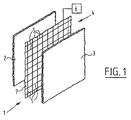
収着ドライヤ又はクリーナ1は、上に収着(吸収又は吸着)材料3の層が配置される板状基材(plate−like substrate)2によって形成される。板状基材2は、例えば空間に対して空気を供給するダクトの壁である、表面Sを画定する。収着材料3は、低臨界溶解温度ポリマであり、例えば、ポリオキサゾリン、ポリ(ジメチルアミノエチルメタクリラート)(pDMAEMa)、又はポリ(N−イソプロピルアクリルアミド)(pNiPAAm)である。あるいは、自立のLCSTポリマを想定することは可能であり、したがって別個の物質の必要性は排除される。 The sorption dryer or cleaner 1 is formed by a plate-like substrate 2 on which a layer of sorption (absorption or adsorption) material 3 is arranged. The plate-like substrate 2 defines a surface S that is a wall of a duct that supplies air to the space, for example. The sorption material 3 is a low critical solution temperature polymer, for example, polyoxazoline, poly (dimethylaminoethyl methacrylate) (pDMAEMa), or poly (N-isopropylacrylamide) (pNiPAAm). Alternatively, it is possible to envision a free-standing LCST polymer, thus eliminating the need for a separate material.
ポリマをその臨界溶解温度まで加熱するよう、収着ドライヤ又はクリーナ1は、加熱手段4を更に備えられる。該手段は、ここではネットワークにおいて接続される加熱ワイヤ5等である複数の加熱素子の形状をとる。加熱手段4は更に、コントロール(control)6を更に有し、ネットワークの異なる部分のスイッチが一度にオンにされる。このようにして加熱手段4の異なる部分は、周期的に活性され、加熱手段4の活性部分は、表面Sに沿って移動する。 The sorption dryer or cleaner 1 is further provided with heating means 4 to heat the polymer to its critical melting temperature. This means takes the form of a plurality of heating elements, here heating wires 5 etc. connected in a network. The heating means 4 further comprises a control 6 in which different parts of the network are switched on at one time. In this way, different parts of the heating means 4 are activated periodically and the active part of the heating means 4 moves along the surface S.
加熱手段4は、基材2上に取り付けられるキャリア7上に配置される。図示される実施例では、キャリア7は、その上へと加熱素子5及びコントロール6がプリントされるフォイルの形状をとり、基材2と収着材料3の層との間において接着される。この結果、大変小型の構造が得られる。これが可能なのは、収着材料3が結局はLCSTポリマであるので低電力の供給のみを必要とするため、である。 The heating means 4 is arranged on a carrier 7 attached on the substrate 2. In the embodiment shown, the carrier 7 takes the form of a foil onto which the heating element 5 and the control 6 are printed, and is bonded between the substrate 2 and the layer of sorption material 3. As a result, a very small structure is obtained. This is possible because the sorption material 3 is ultimately an LCST polymer and only requires a low power supply.
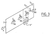
収着ドライヤ又はクリーナ1の使用中、外気等である湿り空気MAは、ファンを用いてダクトを通って吹き出されるか、引き込まれ、このダクトの各壁は、上方に収着材料3の層を有する基材2によって形成される。湿り空気流MAが通り過ぎる際、水分Mは、収着材料3によってそこから引き出され、素早く保持される。このようにして乾燥される空気流Aは、ダクトを出て、空間に供給される前に、更に冷却等の処理をされ得る。 During use of the sorption dryer or cleaner 1, moist air MA, such as outside air, is blown or drawn through the duct using a fan, and each wall of this duct has a layer of sorption material 3 above it. Formed by the substrate 2 having As the moist air stream MA passes, the moisture M is drawn from it by the sorption material 3 and is quickly retained. The air stream A thus dried can be further cooled, etc., before leaving the duct and being supplied to the space.
収着材料3は、飽和する危険性がある程の大量の水分を取っている際、再度水分を放すことによって再生されなければならない。このためには、収着材料は、ポリマが溶液から出て水分が拒絶される臨界溶解温度を上回るまで、加熱される。低臨界溶解温度ポリマ(LCSTポリマ)が収着材料として使用される際、この移行点は、約60乃至70℃等である水の沸点を明らかに下回る温度において、発生する。 The sorbent material 3 must be regenerated by releasing the moisture again when it is taking a large amount of moisture that saturates. For this purpose, the sorption material is heated until it exceeds the critical melting temperature at which the polymer leaves the solution and moisture is rejected. When a low critical solution temperature polymer (LCST polymer) is used as the sorption material, this transition point occurs at a temperature clearly below the boiling point of water, such as about 60-70 ° C.
本発明に従った加熱手段4は、臨界溶解温度を上回って一度に収着材料3の一部に対して適用される一方、該材料の残りは、この温度を下回って維持され、故にその通常の収着作用を保つ。コントロール6の影響を受けて、ダクトの流入側に対して近接する表面Sの一部S1は、例えば最初に加熱及び再生される。少量の水分V’は続いて、通過する湿り空気流MAに対して放され、その後湿り空気流MAは、表面Sの残りの部分に沿って通過する際、収着材料3に対してその水分を放し、よって乾燥されてダクトを出る。加熱される部分S1によって放される更に大部分の水分V’’は、表面Sにそって下方に流れ、続いて収集される。 The heating means 4 according to the invention is applied to a part of the sorption material 3 at a time above the critical melting temperature, while the rest of the material is maintained below this temperature and hence its normal Keeps the sorption effect. Under the influence of the control 6, a part S1 of the surface S that is close to the inflow side of the duct is first heated and regenerated, for example. A small amount of moisture V ′ is subsequently released to the passing humid air stream MA, which then passes along the remaining part of the surface S, with its moisture to the sorption material 3. Then let it dry and leave the duct. Most of the moisture V '' released by the heated part S1 flows down along the surface S and is subsequently collected.
コントロール6は、加熱ワイヤ5のネットワークの他の部分のスイッチをオンにし、その後の部分S2は、加熱及び再生される。湿り空気流MAは、故に、まず第1の部分S1を通る際に乾燥され、続いて第2の部分S2において収着材料3から水分V’を取り、残りの表面Sによって再度更に乾燥される。ここでも、拒絶される水分V’’の更に大部分は、表面Sに沿って下方に再度流れる。 The control 6 switches on the other part of the network of heating wires 5 and the subsequent part S2 is heated and regenerated. The moist air stream MA is therefore first dried as it passes through the first part S1, and subsequently takes moisture V ′ from the sorption material 3 in the second part S2 and is further dried again by the remaining surface S. . Again, a greater part of the rejected moisture V ″ again flows down along the surface S.
故に全体表面は、ネットワークの部分のスイッチを連続的にオン及びオフにすることによって、短時間で再生され得る。 Thus, the entire surface can be regenerated in a short time by successively switching on and off parts of the network.
本発明は、一実施例に基づいて上述されるが、それに制限されることはなく、添付の請求項の範囲内における多くの方途において変更され得る、ことは明らかである。 The present invention has been described above on the basis of one embodiment, but is not limited thereto and it is obvious that it can be modified in many ways within the scope of the appended claims.
Claims (12)
当該方法は、収着される物質が前記収着表面から分離される温度まで前記収着表面を周期的に加熱することによるものであり、
前記表面は、固定されて維持され、加熱手段の作用に対して周期的に露出される、
ことを特徴とする方法。 A method of regenerating a sorption dryer or cleaner having at least one sorption surface comprising:
The method is by periodically heating the sorption surface to a temperature at which the sorbed material is separated from the sorption surface;
The surface is kept fixed and periodically exposed to the action of the heating means,
A method characterized by that.
ことを特徴とする請求項1記載の方法。 Different parts of the surface are continuously heated,
The method of claim 1 wherein:
ことを特徴とする請求項1又は2記載の方法。 At least an active portion of the heating means is moved along the surface;
The method according to claim 1 or 2, characterized in that
ことを特徴とする請求項1乃至3のうちいずれか一項記載の方法。 During the regeneration of part of the sorption dryer or cleaner, the rest of the sorption dryer or cleaner continues to operate normally.
A method according to any one of claims 1 to 3, characterized in that
ことを特徴とする請求項1乃至4のうちいずれか一項記載の方法。 The surface is heated to a temperature below the boiling point of the material separated therefrom;
A method according to any one of claims 1 to 4, characterized in that
収着される物質が前記表面から分離される温度まで前記表面を周期的に加熱する手段を有し、
前記表面は、固定されて維持され、前記加熱手段は、その作用に対して前記表面を周期的に露出するよう適合される、
ことを特徴とする再生装置。 An apparatus for regenerating a sorption dryer or cleaner having at least one sorption surface comprising:
Means for periodically heating the surface to a temperature at which the sorbed material is separated from the surface;
The surface is kept fixed and the heating means is adapted to periodically expose the surface to its action;
A reproducing apparatus characterized by that.
ことを特徴とする請求項6記載の再生装置。 The heating means is adapted to continuously heat different portions of the surface;
The playback apparatus according to claim 6.
ことを特徴とする請求項6又は7記載の再生装置。 The heating means has at least one active portion movable along the surface;
The playback apparatus according to claim 6 or 7, wherein
ことを特徴とする請求項8記載の再生装置。 The heating means has a plurality of heating elements distributed and arranged along the surface, and a control for alternately turning on and off the switches of the heating elements.
9. A playback apparatus according to claim 8, wherein
ことを特徴とする請求項9記載の再生装置。 The heating element is a heating wire connected in a network,
The reproducing apparatus according to claim 9.
ことを特徴とする請求項9又は10記載の再生装置。 The heating element and the control are housed in a carrier connected to the surface,
The playback apparatus according to claim 9 or 10, characterized in that
ことを特徴とする請求項6乃至11のうちいずれか一項記載の再生装置。 The heating means is adapted to heat the surface to a temperature below the boiling point of the material separated from the surface;
The playback apparatus according to claim 6, wherein the playback apparatus is a playback apparatus.
Applications Claiming Priority (2)
| Application Number | Priority Date | Filing Date | Title |
|---|---|---|---|
| NL1030149A NL1030149C1 (en) | 2005-10-10 | 2005-10-10 | Method and device for regenerating a sorption dryer or cleaner. |
| PCT/NL2006/000508 WO2007043863A1 (en) | 2005-10-10 | 2006-10-09 | Method and apparatus for regenerating a sorption dryer or cleaner |
Publications (2)
| Publication Number | Publication Date |
|---|---|
| JP2009511261A true JP2009511261A (en) | 2009-03-19 |
| JP2009511261A5 JP2009511261A5 (en) | 2009-11-26 |
Family
ID=37654949
Family Applications (1)
| Application Number | Title | Priority Date | Filing Date |
|---|---|---|---|
| JP2008535474A Withdrawn JP2009511261A (en) | 2005-10-10 | 2006-10-09 | Method and apparatus for regenerating a sorption dryer or cleaner |
Country Status (8)
| Country | Link |
|---|---|
| US (1) | US20090314160A1 (en) |
| EP (1) | EP1933970A1 (en) |
| JP (1) | JP2009511261A (en) |
| KR (1) | KR20080066932A (en) |
| CN (1) | CN101282777A (en) |
| BR (1) | BRPI0617176A2 (en) |
| NL (1) | NL1030149C1 (en) |
| WO (1) | WO2007043863A1 (en) |
Cited By (6)
| Publication number | Priority date | Publication date | Assignee | Title |
|---|---|---|---|---|
| WO2016035410A1 (en) * | 2014-09-05 | 2016-03-10 | シャープ株式会社 | Humidity conditioning device |
| WO2016035409A1 (en) * | 2014-09-05 | 2016-03-10 | シャープ株式会社 | Humidity conditioning device |
| WO2016068129A1 (en) * | 2014-10-29 | 2016-05-06 | シャープ株式会社 | Hygroscopic material and dehumidifier using same |
| WO2016163159A1 (en) * | 2015-04-08 | 2016-10-13 | シャープ株式会社 | Water collection device and water collection method |
| WO2016194407A1 (en) * | 2015-05-29 | 2016-12-08 | シャープ株式会社 | Dehumidification device and dehumidification method |
| JPWO2015083732A1 (en) * | 2013-12-06 | 2017-03-16 | シャープ株式会社 | Dehumidifier |
Families Citing this family (11)
| Publication number | Priority date | Publication date | Assignee | Title |
|---|---|---|---|---|
| NL1030538C1 (en) * | 2005-11-28 | 2007-05-30 | Eurocore Trading & Consultancy | Device for indirectly cooling an air stream through evaporation. |
| US8366803B2 (en) * | 2007-04-23 | 2013-02-05 | Enbion Inc. | Air cleaner having regenerative filter, and method for regenerative of air cleaner filter |
| CA2932181C (en) | 2009-02-27 | 2019-01-08 | Inventys Thermal Technologies Inc. | Parallel passage fluid contractor structure |
| EP2389854B1 (en) | 2010-05-24 | 2016-08-24 | Electrolux Home Products Corporation N.V. | Device and method for a dishwasher |
| EP2389853A1 (en) * | 2010-05-24 | 2011-11-30 | Electrolux Home Products Corporation N.V. | Sorption drying device for a dishwasher and associated method |
| US10315159B2 (en) | 2010-08-27 | 2019-06-11 | Inventys Thermal Technoogies Inc. | Method of adsorptive gas separation using thermally conductive contactor structure |
| EP2608867B8 (en) | 2010-08-27 | 2017-04-05 | Inventys Thermal Technologies Inc. | Method of adsorptive gas separation using thermally conductive contactor structure |
| NL2011443C (en) * | 2013-09-13 | 2015-03-16 | Oxycom Beheer Bv | Water extracting device. |
| JP6385781B2 (en) * | 2014-10-06 | 2018-09-05 | シャープ株式会社 | Dehumidifier |
| NL2016458B1 (en) | 2016-03-18 | 2017-10-04 | Oxycom Beheer Bv | Smart dehumidifier. |
| TWI608201B (en) * | 2016-04-29 | 2017-12-11 | 財團法人工業技術研究院 | Desiccant wheel |
Family Cites Families (8)
| Publication number | Priority date | Publication date | Assignee | Title |
|---|---|---|---|---|
| DE3578383D1 (en) * | 1984-05-28 | 1990-08-02 | Mitsui Toatsu Chemicals | AGENT FOR THE ABSORPTION AND LEAKAGE OF WATER VAPOR. |
| US5227598A (en) * | 1991-12-23 | 1993-07-13 | General Electric Company | In place regeneration of adsorbents using microwaves |
| KR100252818B1 (en) * | 1992-06-07 | 2000-04-15 | Seibu Giken Kk | Sorbing sheets and laminates having reactivating and invigorating functions |
| FR2738501B1 (en) * | 1995-09-07 | 1997-10-17 | Inst Francais Du Petrole | PROCESS AND DEVICE FOR PURIFYING VASES OF GASEOUS EFFLUENTS LOADED WITH POLLUTANT SUBSTANCES |
| US5902381A (en) * | 1997-05-30 | 1999-05-11 | General Signal Corporation | Dehydrating breather apparatus |
| DE19817546A1 (en) * | 1998-04-14 | 1999-10-21 | Mannesmann Ag | Removal of undesirable components from a gas stream by adsorption |
| DE19823611B4 (en) * | 1998-05-27 | 2005-06-09 | Eads Deutschland Gmbh | Device for cleaning a passenger compartment of a vehicle to be supplied air flow |
| DE10001043A1 (en) * | 2000-01-13 | 2001-07-19 | Behr Gmbh & Co | Desorbable sorption filter, in particular for a heating or air conditioning system of a motor vehicle |
-
2005
- 2005-10-10 NL NL1030149A patent/NL1030149C1/en not_active IP Right Cessation
-
2006
- 2006-10-09 BR BRPI0617176-1A patent/BRPI0617176A2/en not_active IP Right Cessation
- 2006-10-09 US US12/089,687 patent/US20090314160A1/en not_active Abandoned
- 2006-10-09 EP EP06799497A patent/EP1933970A1/en not_active Withdrawn
- 2006-10-09 CN CNA2006800377228A patent/CN101282777A/en active Pending
- 2006-10-09 KR KR1020087010626A patent/KR20080066932A/en not_active Application Discontinuation
- 2006-10-09 WO PCT/NL2006/000508 patent/WO2007043863A1/en active Application Filing
- 2006-10-09 JP JP2008535474A patent/JP2009511261A/en not_active Withdrawn
Cited By (14)
| Publication number | Priority date | Publication date | Assignee | Title |
|---|---|---|---|---|
| JP2018202417A (en) * | 2013-12-06 | 2018-12-27 | シャープ株式会社 | Dehumidifier and ice maker |
| JPWO2015083732A1 (en) * | 2013-12-06 | 2017-03-16 | シャープ株式会社 | Dehumidifier |
| WO2016035409A1 (en) * | 2014-09-05 | 2016-03-10 | シャープ株式会社 | Humidity conditioning device |
| WO2016035410A1 (en) * | 2014-09-05 | 2016-03-10 | シャープ株式会社 | Humidity conditioning device |
| US10099173B2 (en) | 2014-09-05 | 2018-10-16 | Sharp Kabushiki Kaisha | Humidity controlling apparatus |
| JPWO2016035409A1 (en) * | 2014-09-05 | 2017-04-27 | シャープ株式会社 | Humidity control device |
| JPWO2016035410A1 (en) * | 2014-09-05 | 2017-04-27 | シャープ株式会社 | Humidity control device |
| JPWO2016068129A1 (en) * | 2014-10-29 | 2017-06-01 | シャープ株式会社 | Hygroscopic material and dehumidifier using the same |
| WO2016068129A1 (en) * | 2014-10-29 | 2016-05-06 | シャープ株式会社 | Hygroscopic material and dehumidifier using same |
| US10539334B2 (en) | 2014-10-29 | 2020-01-21 | Sharp Kabushiki Kaisha | Hygroscopic material and dehumidifier using same |
| WO2016163159A1 (en) * | 2015-04-08 | 2016-10-13 | シャープ株式会社 | Water collection device and water collection method |
| JP2016198705A (en) * | 2015-04-08 | 2016-12-01 | シャープ株式会社 | Water accumulation device and water accumulation method |
| JP2016221445A (en) * | 2015-05-29 | 2016-12-28 | シャープ株式会社 | Dehumidification apparatus and dehumidification method |
| WO2016194407A1 (en) * | 2015-05-29 | 2016-12-08 | シャープ株式会社 | Dehumidification device and dehumidification method |
Also Published As
| Publication number | Publication date |
|---|---|
| CN101282777A (en) | 2008-10-08 |
| BRPI0617176A2 (en) | 2011-07-12 |
| KR20080066932A (en) | 2008-07-17 |
| NL1030149C1 (en) | 2007-04-11 |
| WO2007043863A1 (en) | 2007-04-19 |
| EP1933970A1 (en) | 2008-06-25 |
| US20090314160A1 (en) | 2009-12-24 |
Similar Documents
| Publication | Publication Date | Title |
|---|---|---|
| JP2009511261A (en) | Method and apparatus for regenerating a sorption dryer or cleaner | |
| KR100266344B1 (en) | How to recover volatile organics | |
| JP2673300B2 (en) | Low concentration gas sorption machine | |
| US20180328601A1 (en) | Heat recovery adsorber as ventilation system in buildings | |
| EP1928580B1 (en) | Method and device for separating a substance from a process gas | |
| JP2001062242A (en) | Dehumidifying device | |
| WO2016194407A1 (en) | Dehumidification device and dehumidification method | |
| JPH0118335B2 (en) | ||
| JP2007517663A (en) | Method for producing purified compressed gas and adsorbent wheel system | |
| JPH04171019A (en) | Process for removing water content in mixed gas | |
| JP5026345B2 (en) | Adsorbent system and method for regenerating the system | |
| JP2006061758A (en) | Carbon dioxide remover | |
| JP2012166128A5 (en) | ||
| KR101501727B1 (en) | Dehumidifier using desicant | |
| JP2010167178A (en) | Washing drying machine | |
| US20080083336A1 (en) | Electrically conductive adsorptive honeycombs for drying of air | |
| JP5207014B2 (en) | Organic solvent dehydrator | |
| JP4264740B2 (en) | Small desiccant air conditioner | |
| JPH0115780B2 (en) | ||
| MX2008004695A (en) | Method and apparatus for regenerating a sorption dryer or cleaner | |
| JP3620650B2 (en) | Gas processing apparatus and processing method | |
| JP7277801B2 (en) | adsorption system | |
| KR102449592B1 (en) | Desiccant Dehumidification System | |
| JPH047015A (en) | Dehumidifier | |
| JP2002273148A (en) | Humidistat |
Legal Events
| Date | Code | Title | Description |
|---|---|---|---|
| A521 | Written amendment |
Free format text: JAPANESE INTERMEDIATE CODE: A523 Effective date: 20091007 |
|
| A621 | Written request for application examination |
Free format text: JAPANESE INTERMEDIATE CODE: A621 Effective date: 20091007 |
|
| A761 | Written withdrawal of application |
Free format text: JAPANESE INTERMEDIATE CODE: A761 Effective date: 20110419 |
|
| A521 | Written amendment |
Free format text: JAPANESE INTERMEDIATE CODE: A821 Effective date: 20110419 |