JP2009511135A - Motion detection device and motion detection clothing - Google Patents
Motion detection device and motion detection clothing Download PDFInfo
- Publication number
- JP2009511135A JP2009511135A JP2008534826A JP2008534826A JP2009511135A JP 2009511135 A JP2009511135 A JP 2009511135A JP 2008534826 A JP2008534826 A JP 2008534826A JP 2008534826 A JP2008534826 A JP 2008534826A JP 2009511135 A JP2009511135 A JP 2009511135A
- Authority
- JP
- Japan
- Prior art keywords
- sub
- members
- movement
- electrical
- contractors
- Prior art date
- Legal status (The legal status is an assumption and is not a legal conclusion. Google has not performed a legal analysis and makes no representation as to the accuracy of the status listed.)
- Pending
Links
Images


Classifications
-
- A—HUMAN NECESSITIES
- A61—MEDICAL OR VETERINARY SCIENCE; HYGIENE
- A61B—DIAGNOSIS; SURGERY; IDENTIFICATION
- A61B5/00—Measuring for diagnostic purposes; Identification of persons
- A61B5/103—Detecting, measuring or recording devices for testing the shape, pattern, colour, size or movement of the body or parts thereof, for diagnostic purposes
-
- G—PHYSICS
- G01—MEASURING; TESTING
- G01D—MEASURING NOT SPECIALLY ADAPTED FOR A SPECIFIC VARIABLE; ARRANGEMENTS FOR MEASURING TWO OR MORE VARIABLES NOT COVERED IN A SINGLE OTHER SUBCLASS; TARIFF METERING APPARATUS; MEASURING OR TESTING NOT OTHERWISE PROVIDED FOR
- G01D5/00—Mechanical means for transferring the output of a sensing member; Means for converting the output of a sensing member to another variable where the form or nature of the sensing member does not constrain the means for converting; Transducers not specially adapted for a specific variable
- G01D5/12—Mechanical means for transferring the output of a sensing member; Means for converting the output of a sensing member to another variable where the form or nature of the sensing member does not constrain the means for converting; Transducers not specially adapted for a specific variable using electric or magnetic means
- G01D5/14—Mechanical means for transferring the output of a sensing member; Means for converting the output of a sensing member to another variable where the form or nature of the sensing member does not constrain the means for converting; Transducers not specially adapted for a specific variable using electric or magnetic means influencing the magnitude of a current or voltage
- G01D5/16—Mechanical means for transferring the output of a sensing member; Means for converting the output of a sensing member to another variable where the form or nature of the sensing member does not constrain the means for converting; Transducers not specially adapted for a specific variable using electric or magnetic means influencing the magnitude of a current or voltage by varying resistance
- G01D5/165—Mechanical means for transferring the output of a sensing member; Means for converting the output of a sensing member to another variable where the form or nature of the sensing member does not constrain the means for converting; Transducers not specially adapted for a specific variable using electric or magnetic means influencing the magnitude of a current or voltage by varying resistance by relative movement of a point of contact or actuation and a resistive track
-
- A—HUMAN NECESSITIES
- A61—MEDICAL OR VETERINARY SCIENCE; HYGIENE
- A61B—DIAGNOSIS; SURGERY; IDENTIFICATION
- A61B2562/00—Details of sensors; Constructional details of sensor housings or probes; Accessories for sensors
- A61B2562/02—Details of sensors specially adapted for in-vivo measurements
- A61B2562/0261—Strain gauges
-
- A—HUMAN NECESSITIES
- A61—MEDICAL OR VETERINARY SCIENCE; HYGIENE
- A61B—DIAGNOSIS; SURGERY; IDENTIFICATION
- A61B2562/00—Details of sensors; Constructional details of sensor housings or probes; Accessories for sensors
- A61B2562/16—Details of sensor housings or probes; Details of structural supports for sensors
- A61B2562/164—Details of sensor housings or probes; Details of structural supports for sensors the sensor is mounted in or on a conformable substrate or carrier
-
- A—HUMAN NECESSITIES
- A61—MEDICAL OR VETERINARY SCIENCE; HYGIENE
- A61B—DIAGNOSIS; SURGERY; IDENTIFICATION
- A61B5/00—Measuring for diagnostic purposes; Identification of persons
- A61B5/45—For evaluating or diagnosing the musculoskeletal system or teeth
- A61B5/4528—Joints
-
- A—HUMAN NECESSITIES
- A61—MEDICAL OR VETERINARY SCIENCE; HYGIENE
- A61B—DIAGNOSIS; SURGERY; IDENTIFICATION
- A61B5/00—Measuring for diagnostic purposes; Identification of persons
- A61B5/68—Arrangements of detecting, measuring or recording means, e.g. sensors, in relation to patient
- A61B5/6801—Arrangements of detecting, measuring or recording means, e.g. sensors, in relation to patient specially adapted to be attached to or worn on the body surface
- A61B5/6802—Sensor mounted on worn items
- A61B5/6804—Garments; Clothes
Landscapes
- Health & Medical Sciences (AREA)
- Life Sciences & Earth Sciences (AREA)
- Physics & Mathematics (AREA)
- Surgery (AREA)
- General Health & Medical Sciences (AREA)
- Biophysics (AREA)
- Pathology (AREA)
- Engineering & Computer Science (AREA)
- Biomedical Technology (AREA)
- Heart & Thoracic Surgery (AREA)
- Medical Informatics (AREA)
- Molecular Biology (AREA)
- Dentistry (AREA)
- Animal Behavior & Ethology (AREA)
- Oral & Maxillofacial Surgery (AREA)
- Public Health (AREA)
- Veterinary Medicine (AREA)
- General Physics & Mathematics (AREA)
- Measurement Of The Respiration, Hearing Ability, Form, And Blood Characteristics Of Living Organisms (AREA)
- Measurement Of Length, Angles, Or The Like Using Electric Or Magnetic Means (AREA)
- Testing Or Calibration Of Command Recording Devices (AREA)
- Measuring And Recording Apparatus For Diagnosis (AREA)
- Manipulator (AREA)
- Professional, Industrial, Or Sporting Protective Garments (AREA)
Abstract
本発明は、動き検出装置である。この装置は、手足のような人の部分の動きを検出するのに使用できる。好適には、この装置は、a)電源、b)人あるいは対象物の、互いに動く、複数の部分に直接的あるいは間接的に取付けることができる、2つあるいはそれ以上の収縮器、および、c)電気的に連通する、長手方向に伸縮不能の電気的部材を具備する。電気的部材は、直接的あるいは間接的に案内構造体によって支持されることができる。この案内構造体は、この部材の長手方向を横切る方向の変形を最小化するように構成されている。収縮器の相対的な動きによって、収縮器間の距離が変化する。この相対的な動きを、収縮器間の電気抵抗の変化として、測定する、あるいは、検出することができる。 The present invention is a motion detection device. This device can be used to detect the movement of human parts such as limbs. Preferably, the device comprises a) a power source, b) two or more retractors that can be directly or indirectly attached to multiple parts of a person or object that move relative to each other, and c ) It has an electrical member that is in electrical communication and is not stretchable in the longitudinal direction. The electrical member can be supported by the guide structure directly or indirectly. The guide structure is configured to minimize deformation in a direction across the longitudinal direction of the member. The relative movement of the contractors changes the distance between the contractors. This relative movement can be measured or detected as a change in electrical resistance between the contractors.
Description
本発明は、人、動物、あるいは、機械のような対象物の運動、特に、それらの部分の動きを検出あるいは監視する装置及び衣服に関する。たとえば、本発明は、アスリートあるいは患者の腕及び脚の動きを監視あるいは検出することに使用することができる。同様に、本発明は、ロボットあるいは機械の動きを監視あるいは検出することにも使用することができる。 The present invention relates to an apparatus and a garment for detecting or monitoring the movement of an object such as a person, animal or machine, in particular the movement of those parts. For example, the present invention can be used to monitor or detect the movement of an athlete or patient's arms and legs. Similarly, the present invention can be used to monitor or detect the movement of a robot or machine.
本発明の主題である技術は、トレーニング、骨格の関節、あるいは、筋肉損傷のリハビリテーション、生体医学監視、医療用織物、負傷兵のトリアージ・サービス、その他の軍事的及び安全的応用を含む(これですべてではない)、広い適用分野で使用できることがわかる。別の例では、本発明は、織物のような媒体の形状あるいは構成、より具体的には、ヨットの帆の形状あるいは構成を調整する道具として使用することもできる。さらに別の例では、本発明は、人あるいは対象物の運きによって、音を生成することが機能である、あるいは、生成された音を制御する、音楽機器に適用することができる。 The technology that is the subject of this invention includes training, skeletal joint or muscle injury rehabilitation, biomedical surveillance, medical fabrics, injured triage services, and other military and safety applications. It can be used in a wide range of applications. In another example, the present invention can be used as a tool to adjust the shape or configuration of a medium such as a fabric, more specifically the shape or configuration of a sail of a yacht. In yet another example, the present invention can be applied to a music device that has a function of generating a sound by controlling a person or an object or that controls the generated sound.
帆との手の動きを測定する装置のひとつの例が、特許文献1に記載されている。その装置は、人の手のヒンジ様の動き、あるいは、関節の動きを検出する、角度測定器の列を具備している。関節の動きは、ストレインゲージに負荷される応力に応じて電気伝導性が変化する、ストレインゲージの列を使用して監視される。各々のストレインゲージは、人に装着されたグローブの部分を形成して、それらのストレインゲージは、掌あるいはグローブの上面に配置されている。人が指を曲げたとき、電気信号の変化は受信され、そして、電気信号をコンピュータ・インターフェイスを使用して特定の機能を実行するものと解釈することができる。 One example of an apparatus for measuring the movement of a hand with a sail is described in Patent Document 1. The device comprises a row of angle measuring devices that detect the movement of a person's hinges or joints. The movement of the joint is monitored using a strain gauge array in which the electrical conductivity changes in response to the stress applied to the strain gauge. Each strain gauge forms a part of a glove worn on a person, and these strain gauges are arranged on the upper surface of the palm or glove. When a person bends a finger, a change in the electrical signal is received and the electrical signal can be interpreted to perform a specific function using the computer interface.
別の例は、ピータ・ギプス、ハリー・アサダの“多軸人体関節角度測定用の身につけることが可能な伝導性繊維センサ”と題する、論文(非特許文献1)に記載された装置である。この論文は、レーヨン、コットン、および、ゴムを含む編まれた繊維スリーブを具備した、従来のニー・サポートの形状を持つ装置を記述している。電気伝導性繊維は、永久的に、ひとつの伝導点で膝関節の上のニー・サポートに取付けられ、ニー・サポート繊維の外側でその関節をまたいで取付けられている。この伝導性繊維は、関節をまたいで自由に滑る必要があるので、スリーブに縫い合わせあるいは編み合わせされていない。装着したとき膝の下の位置にあって使用時に伝導性繊維を張った状態にする、永久的にスリーブに取付けられている、弾性を持つコード(弾性コード)は、伝導性繊維の反対側の端に連結している。関節が動きと、その弾性コードの長さが変わり、伝導性繊維を、それらの伝導点間の回路を形成するように永久にその繊維の中に縫い込んである、もうひとつの伝導点を通り過ぎて引張る。関節を曲げると、2つの伝導点間の伝導性繊維の長さが増大して、2つの伝導点間の電気抵抗が電圧分割器あるいはブリッジ回路を使用して測定される。最終的には、抵抗の変化は、関節の動きに関する情報を提供するように、解釈されて分析されることができる。 Another example is a device described in a paper (Non-Patent Document 1) entitled “A wearable conductive fiber sensor for multi-axis human joint angle measurement” by Peter Gyps, Harry Asada. is there. This paper describes a device with the shape of a conventional knee support with a knitted fiber sleeve containing rayon, cotton and rubber. The electrically conductive fiber is permanently attached to the knee support above the knee joint at one conduction point and across the joint outside the knee support fiber. This conductive fiber is not stitched or knitted into the sleeve because it must slide freely across the joint. The elastic cord, which is permanently attached to the sleeve, is placed under the knee when worn and tensions the conductive fiber when in use. It is connected to the end. As the joint moves, the length of its elastic cord changes and the conductive fiber passes through another conduction point that is permanently sewn into that fiber to form a circuit between those conduction points. Pull. Bending the joint increases the length of the conductive fiber between the two conduction points and the electrical resistance between the two conduction points is measured using a voltage divider or bridge circuit. Ultimately, resistance changes can be interpreted and analyzed to provide information about joint movement.
信頼性の高い操作を維持するために、装置は、伝導性繊維に常に張力がかかった状態にある、弾性コードに依存している。弾性コードが不具合を生じたとき、それらの点の間の伝導性繊維の長さは、膝関節の曲がりの程度を表さない。加えて、我々の考えでは、この設計は、膝の後ろ側、あるいは、肘の内側のような、伝導性繊維が関節の内側に配置されている状況に特に適しているわけではない。 In order to maintain reliable operation, the device relies on elastic cords in which the conductive fibers are always under tension. When the elastic cord fails, the length of the conductive fibers between those points does not represent the degree of knee joint bending. In addition, in our view, this design is not particularly suitable for situations where conductive fibers are placed inside the joint, such as the back of the knee or the inside of the elbow.
本発明の目的は、関節あるいは変形した表面の動きを監視することに使用することができる代替装置を提供することである。
本発明によれば、動き、たとえば、限定ではないが、彼らの手足、彼らの手足の部分、あるいは、変形可能な表面などの、人の部分の動きを検出する装置が提供される。この装置は、
a)互いに相対的に運動する、人あるいは対象物の部分に、直接的あるいは間接的に装着できて、使用時、人あるいは対象物が動いた結果、複数のコネクタ間のスペースが変わることが出来る、2あるいはそれ以上の収縮器と、
b)細長い電気的部材であって、使用時、電流を伝導してその収縮器と電気的に接続され、その電気的部材の長手方向の軸に沿って実質的に伸張せず、さらに、i)少なくとも部分的に、その電気的部材の長手方向の軸を横切る方向に弾性的に変形可能、であって/であるか、ii)その電気的部材の有効長が収縮器間の最小の電気抵抗を持つ経路を規定して、収縮器間の電気抵抗の変化として動きを測定あるいは検出できるように、収縮器の相対運動が収縮器の間の、その電気的部材の有効長を変化できるように、その電気的部材の長手方向の軸を横切る方向の変形を最小化するように構成された、弾性的な特性を持つ、案内構造体に、直接的にあるいは間接的に支持される、細長い電気的部材と、
を具備する。
In accordance with the present invention, an apparatus is provided for detecting movement, eg, movement of a human part, such as, but not limited to, their limbs, parts of their limbs, or deformable surfaces. This device
a) Can be directly or indirectly attached to a part of a person or object that moves relative to each other, and when used, the space between a plurality of connectors can change as a result of movement of the person or object. Two or more contractors;
b) an elongated electrical member that, in use, conducts electrical current and is electrically connected to the retractor, does not substantially extend along the longitudinal axis of the electrical member, and i Ii) is / is at least partially elastically deformable in a direction transverse to the longitudinal axis of the electrical member, or ii) the effective length of the electrical member is minimal The relative movement of the contractor can change the effective length of its electrical member between the contractors so that a path with resistance can be defined and movement can be measured or detected as a change in electrical resistance between the contractors. An elongated, supported directly or indirectly by a guide structure with elastic properties, configured to minimize deformation in a direction transverse to the longitudinal axis of the electrical member An electrical member;
It comprises.
本発明が提供する有利な効果は、収縮器間の電気抵抗の変化を監視することによって、対象物の動きが容易に検出および分析できることである。本発明が提供する別の有利な効果は、部材の弾性的な性質のために、装置が比較的複雑でない単純な構造を持っていることである。 An advantageous effect provided by the present invention is that object motion can be easily detected and analyzed by monitoring changes in electrical resistance between the contractors. Another advantageous effect provided by the present invention is that the device has a simple structure that is relatively uncomplicated due to the elastic nature of the member.
好適には、部材の弾性的な変形可能な性質、および/あるいは、案内構造体の弾性的な特性は、収縮器の間の部材の曲がりの程度を最小化することが好ましい。部材の電気抵抗は、その長さの関数であり、それ故、収縮器の間の部材の曲がりを最小化することによって、部材の有効長と最小抵抗を持つ経路も最小化される。 Preferably, the elastic deformable nature of the member and / or the elastic properties of the guide structure preferably minimize the degree of bending of the member between the retractors. The electrical resistance of the member is a function of its length, and thus minimizing the bending of the member between the retractors also minimizes the path with the effective length of the member and the minimum resistance.
複数の収縮器は、動きを検出あるいは監視される、対象物あるいは人に、ストラップ、粘着、その他の適当な方法で、直接固定される、個別の部品とすることは可能ではあるが、好適には、装置は、その上に収縮器を装着でき、監視される部分に装着できる、可撓性の基体を具備することが好ましい。より具体的には、基体は、収縮器が監視される部分に位置合わせされるように、対象物に装着することができる。 Multiple contractors can be separate parts that are directly secured to the object or person whose movement or motion is detected or monitored by straps, adhesives, or other suitable methods, but preferably Preferably, the device comprises a flexible substrate on which the retractor can be mounted and which can be mounted on the monitored part. More specifically, the substrate can be attached to the object such that the retractor is aligned with the portion to be monitored.
さらに、好適には、基体は、動いている間、対象物上の実質的に同一な位置に収縮器が保持されるように、対象物の形状をとることができることが好ましい。 Furthermore, it is preferred that the substrate is able to take the shape of the object so that the retractor is held in substantially the same position on the object while moving.
さらに、好適には、期待は織物であることが好ましく、限定ではないが、ナイロン、ゴム、スパンテックス、および、lycra(商標)のような、弾性物質を具備することもできる。 In addition, the expectation is preferably a woven fabric, which may include elastic materials such as, but not limited to, nylon, rubber, spantex, and lycra ™.
好適には、装置は、さらに、部材に電気的に接続された、電源を具備することが望ましい。 Preferably, the device further comprises a power source electrically connected to the member.
好適には、装置は、複数の収縮器の電気抵抗の変化を記録する手段を具備することが望ましい。 Preferably, the device comprises means for recording changes in the electrical resistance of the plurality of contractors.
さらに、好適には、電気抵抗の変化を記録する手段は、電気抵抗を分析して対象物の動き分析するコンピュータを具備することが望ましい。 Furthermore, it is preferable that the means for recording the change in the electric resistance includes a computer for analyzing the electric resistance and analyzing the movement of the object.
それぞれ、部材の有効長をどのように最小化して、最小抵抗の経路を規定するかに関連する、本発明の代替実施態様を、以下、詳細に記載する。 Alternative embodiments of the present invention, each relating to how to minimize the effective length of the member and define the path of minimum resistance, are described in detail below.
第一の実施態様によれば、好適には、収縮器同士が離れるように動くとき、部材が、張った状態の収縮器を通して滑るように、収縮器が互いに向かって動くとき、部材の弾性的に変形する性質によって、部材が収縮器を通して滑ることができるように、部材は、少なくともひとつの収縮器に摺動可能に接続されていることが望ましい。部材の弾性的に変形する性質によって、特に、部材の曲がりが最小である間、部材を曲がらずに、部材は、収縮器を通して滑ることができる。 According to the first embodiment, preferably, when the retractors move away from each other, the elastic of the members when the retractors move toward each other so that the members slide through the tensioned retractors. The member is preferably slidably connected to at least one retractor so that the member can slide through the retractor due to its deformable nature. Due to the elastically deforming nature of the member, the member can slide through the retractor without bending the member, especially while the bending of the member is minimal.
本実施態様によれば、部材は、両方の収縮器に摺動可能に接続して、収縮器同士が離れるように動くとき、部材を張った状態で配置し、収縮器が互いに向かって動くとき、圧縮された状態で配置することも可能である。部材がひとつあるいはそれ以上の収縮器に摺動可能に接続されているか否かに係わらず、部材の弾性的に変形する性質によって、収縮器間の如何なる曲がりも可能な限り滑らかであることが保証される。その結果、有効長、したがって、最小抵抗を持つ経路は、最小化される。 According to this embodiment, the member is slidably connected to both contractors and when the contractors move away from each other, when the members are placed in tension and the contractors move toward each other It is also possible to arrange in a compressed state. Regardless of whether the member is slidably connected to one or more contractors, the elastically deformable nature of the members ensures that any bend between the contractors is as smooth as possible. Is done. As a result, the path with the effective length and hence the minimum resistance is minimized.
加えて、収縮器が互いに向かうあるいは離れるとき、収縮器は、平面を越えて動く。この点では、部材は、収縮器が平面を越えて動く、その平面を横切るように配置することができるが、好適には、部材は、収縮器がこれを越えて動く、その面に実質的に平行あるいは同一面内に配置することが好ましい。この状況下で、部材は、本質的に、I字型の形状、あるいは、直線的な構成に配置されていると言うことも出来る。 In addition, as the contractors move toward or away from each other, the contractors move beyond the plane. In this regard, the member can be positioned across the plane where the retractor moves beyond the plane, but preferably the member is substantially on that plane where the retractor moves beyond it. It is preferable to arrange in parallel or in the same plane. Under this circumstance, it can be said that the members are essentially arranged in an I-shape or in a linear configuration.
部材は、収縮器の間に位置しない、屈曲した尾部を持つことも可能である。このような状態では、部材は、本質的に、J字型の形状に保持されていると言うことも出来る。 The member can also have a bent tail that is not located between the retractors. In such a state, it can be said that the member is essentially held in a J-shape.
第二の実施態様によれば、好適には、部材は、少なくとも2つの収縮器に固定的に接続されて、電気的部材は、収縮器の間の部材が非直線的部分を持ち、短絡手段が非直線的部分を、最小電気抵抗経路を規定する、部材の有効長から電気的に絶縁するように構成され、使用中に、収縮器の間の距離が変化して、このことが、最小抵抗経路を規定する、部材の有効長を変えるのに応じて、非直線的部分に含まれる部材の長さは変化することが望ましい。 According to the second embodiment, preferably the member is fixedly connected to at least two contractors, the electrical member has a non-linear portion between the contractors and the shorting means Is configured to electrically insulate the non-linear portion from the effective length of the member defining a minimum electrical resistance path, and during use, the distance between the contractors changes, which is the minimum As the effective length of the member defining the resistance path is changed, it is desirable that the length of the member included in the non-linear portion changes.
好適には、非直線的部分は、少なくとも180°だけ方向が変化する、部分であることが望ましい。 Preferably, the non-linear portion is a portion that changes direction by at least 180 °.
好適には、短絡手段は、部材がそれ自身に接触する場所であり、非直線的部分は、ループの大きさの変化に応じて、収縮器間の部材の有効長も変わるように、大きさが変わることの出来る、部材の中で少なくとも360°のループを含むことが望ましい。この状況下では、部材の非線形的部分と部材の隣接する部分は、e字型形状を持っていて、部材の方向の360°より大きい変化を含んでいると言うこともできる。 Preferably, the shorting means is where the member contacts itself, and the non-linear portion is sized such that the effective length of the member between the retractors changes as the size of the loop changes. It is desirable to include at least a 360 ° loop in the member that can vary. Under this circumstance, it can also be said that the non-linear part of the member and the adjacent part of the member have an e-shape and contain a change of more than 360 ° in the direction of the member.
たとえば、収縮器が互いに向かって動くとき、部材の弾性的な性質によって、ループの大きさが増大して、その結果、最小電気抵抗経路を規定する、収縮器間の部材の長さを低減する。逆に、収縮器同士が離れるように動くとき、ループの大きさが縮小して、その結果、最小電気抵抗経路を規定する、収縮器間の部材の長さを増大する。 For example, when the retractors move toward each other, the elastic nature of the members increases the size of the loop, thereby reducing the length of the members between the retractors, defining a minimum electrical resistance path . Conversely, when the contractors move away from each other, the size of the loop is reduced, thereby increasing the length of the member between the contractors that defines the minimum electrical resistance path.
好適には、短絡回路手段は、部材の非直線部分に接続され、部材の非直線部分をまたぐ、ブリッジ部分を含むことが好ましい。 Preferably, the short circuit means includes a bridge portion connected to the non-linear portion of the member and straddling the non-linear portion of the member.
さらに、好適には、部材の非直線部分は、部材の中に少なくとも1つのU字型形状を含み、ブリッジが部材の有効長、部材の非直線部分から外れていることが望ましい。部材が2つのU字型形状と2つのブリッジ部を含む状況では、部材は、実効的に、非直線部分を持つことになり、部材は、S字型形状を持っていると言うことができる。 Further, preferably, the non-linear portion of the member includes at least one U-shaped shape in the member, and the bridge is off the effective length of the member, the non-linear portion of the member. In situations where the member includes two U-shaped shapes and two bridge portions, the member will effectively have a non-linear portion, and it can be said that the member has an S-shaped shape. .
第三の実施態様によれば、好適には、部材は、2つあるいはそれ以上の下位の部品(部品の部品、サブ部材)を含み、各々のサブ部材は、少なくとも1つの他のサブ部材に接触しており、 1つあるいはそれ以上のサブ部材へのあるいはからの接続点の相対的な動きによって、接続点がシフトすることで、最小抵抗経路を規定する、部材の有効長が変化することが望ましい。 According to the third embodiment, preferably the member comprises two or more subparts (part parts, sub-members), each sub-member being at least one other sub-member. The effective length of the member, which defines the minimum resistance path, changes as the connection point shifts due to the relative movement of the connection point to or from one or more sub-members. Is desirable.
サブ部材は、部材の軸が実質的に平行になる、あるいは、互いに横切るように配置されることが出来る。互いに平行に部材が配置された状況では、好適には、ひとつのサブ部材が少なくとも1つの他の部材に沿って摺動可能に接続される様式で、部材は摺動可能に互いに接続されることが好ましい。 The sub-members can be arranged such that the axes of the members are substantially parallel or cross each other. In the situation where the members are arranged parallel to each other, the members are preferably slidably connected to each other in a manner in which one sub-member is slidably connected along at least one other member. Is preferred.
さらに、好適には、サブ部材が2つの接続点で接続されて、複数の部材が、それらが平行関係に接続されるように、接続されることが好ましい。 Furthermore, it is preferable that the sub-members are connected at two connection points, and the plurality of members are connected such that they are connected in a parallel relationship.
さらに、好適には、各々のサブ部材は、隣接するサブ部材を係合して、これによって、接続点を規定する、エンド・フックを具備することが望ましい。 Further, preferably, each sub-member has an end hook that engages an adjacent sub-member thereby defining a connection point.
部材が互いに横切るように配置される状況では、サブ部材は接続点で接触して、サブ部材間の最小電気抵抗経路は複数のサブ部材に接続しているサブ部材の部分および接続点に沿って規定される。 In situations where the members are placed across each other, the sub-members touch at the connection points, and the minimum electrical resistance path between the sub-members is along the portion of the sub-member connected to the plurality of sub-members and the connection points It is prescribed.
収縮器の間の相対的な動きに応じて、接続点は、少なくとも1つのサブ部材に沿って動くことができる。 Depending on the relative movement between the retractors, the connection point can move along at least one sub-member.
X字型形状にて部材が互いに横切るように配置され、隣接するサブ部材の端が複数の収縮器に固定的に接続されて、接続点がX字型形状の中央部にある状況では、サブ部材の有効長は、本質的に、V字型形状を形成する。 In a situation where the members are arranged in an X-shaped shape so as to cross each other, the ends of adjacent sub-members are fixedly connected to a plurality of contractors, and the connection point is in the center of the X-shaped shape, The effective length of the member essentially forms a V-shape.
本発明によれば、手足、あるいは、手足の部分のような、人の部分の動きを検出する衣服が提供される。この衣服は、
a)衣服上の選択した部分に、直接的あるいは間接的に装着されて、衣服がまとわれた時に、人が動いた結果、複数のコネクタ間のスペースが変わることが出来る、2あるいはそれ以上の収縮器と、
b)細長い電気的部材であって、使用時、電流を伝導してその収縮器と電気的に接続され、その電気的部材の長手方向の軸に沿って実質的に伸張せず、さらに、i)少なくとも部分的に、その電気的部材の長手方向の軸を横切る方向に弾性的に変形可能、であり、かつ/または、ii)その電気的部材の有効長が収縮器間の最小の電気抵抗を持つ経路を規定して、収縮器間の電気抵抗の変化として動きを測定あるいは検出できるように、収縮器の相対運動が収縮器の間の、その電気的部材の有効長を変化できるように、その電気的部材の長手方向の軸を横切る方向の変形を最小化するように構成された、弾性的な特性を持つ、案内構造体に、直接的にあるいは間接的に支持される、細長い電気的部材と、
を具備する。
According to the present invention, there is provided a garment for detecting movement of a human part, such as a limb or a part of a limb. This garment
a) The space between multiple connectors can change as a result of the movement of a person when the garment is worn directly or indirectly on a selected part of the garment. 2 or more With a contractor,
b) an elongated electrical member that, in use, conducts electrical current and is electrically connected to the retractor, does not substantially extend along the longitudinal axis of the electrical member, and i ) At least partially elastically deformable in a direction transverse to the longitudinal axis of the electrical member, and / or ii) the effective length of the electrical member is the minimum electrical resistance between the contractors So that the relative movement of the contractor can change the effective length of its electrical member between the contractors so that movement can be measured or detected as a change in electrical resistance between the contractors. An elongated electrical, directly or indirectly supported by a guide structure having elastic properties, configured to minimize deformation in a direction transverse to the longitudinal axis of the electrical member The target member,
It comprises.
本発明の衣服は、本発明の装置の特徴を、その中の任意の1つを単独で、あるいは、任意の組み合わせで、具備することもできる。 The garment of the present invention can also comprise the features of the apparatus of the present invention, any one of them alone or in any combination.
衣服は、肘、手首、指、肩、首、背中、腰、膝、くるぶし、あるいは、つま先のような、如何なる人体の関節の動きをも検出あるいは監視することに使用することができる。衣服が、人が着た、シャツ、あるいは、上着である状況では、本発明は、人の肘の相対的な角度的な位置を監視して、ギターの音響のような、出力を制御することに使用することができる。どのようにして、人の肘の相対的な角度的な位置を使用して、ギターの音響のような音響機器の音を制御して刺激することができるかに関するより詳細な説明は、我々の特許文献2とこれに続くそこで参照されている出願を参照していただきたい。 The garment can be used to detect or monitor the movement of any human joint, such as elbows, wrists, fingers, shoulders, necks, backs, hips, knees, ankles, or toes. In situations where the garment is a person, shirt or jacket, the present invention monitors the relative angular position of the person's elbow and controls the output, such as the acoustics of a guitar. Can be used for that. A more detailed explanation of how the relative angular position of a person's elbow can be used to control and stimulate the sound of an acoustic device such as the acoustics of a guitar is our Reference should be made to U.S. Pat.
複数の実施態様は、同一の、あるいは、実質的に同様の、多くの特徴を持つので、便宜上、本明細書および添付の図面の中で一貫してこれらの特徴を同定するために同一の参照番号を付している。 Since multiple embodiments have many features that are the same or substantially similar, for the sake of convenience, the same reference will be used to identify these features consistently throughout this specification and the accompanying drawings. It is numbered.
各々の図は、その長手方向の軸を横切る方向に弾性的に変形可能な、細長い電気的部材10を持つ、動き検出装置の動き検出器を示している。言い換えると、電気的部材10は、その軸を横切る方向に変形あるいは屈曲されたとき、跳ね返る能力を持っている。加えて、電気的部材10は、その軸に平行な方向には、実質的に伸張せず、その結果、部材は、一時的にも永久的にも伸びて部材の長さを変えることができない。
Each figure shows a motion detector of a motion detection device having an elongated
各々の実施態様に共通する、別の特徴は、2あるいは可能ならそれ以上の、部材に電気的に接続された接触器を具備した、電源である。各々の接触器は、i)その点で電源が部材に固定的に接続されている、固定接続点11、ii)部材10と電源の間の、部材10に沿って滑ることができ、これによって、電源との接続点間の最小電気抵抗経路を規定する、部材10の有効長を変化させる手段を提供する、浮動接続点12のいずれか一方であることができる。
Another feature common to each embodiment is a power source with two or possibly more contactors electrically connected to the member. Each contactor is capable of sliding along the
浮動接続点12は、たとえば、(シールデックスの銀メッキされたナイロン糸、125/17、2つ縒り、のような)銀をコートされたナイロン伝導性糸などの伝導性の糸を、ループあるいは開口部を形成する、織物の基体の中に、縫って、織って、あるいは、編んで、供給され、部材10は、1つあるいはそれ以上のループを介して糸を通す。理想的には、ループは、通常の応力が掛かっていない位置から捻られている。このようにループを捻ることで、部材10と接続点11との連続的な電気的な接続を促進する。
Floating
電源は、電流を伝導する部材10になる、接続点11、12間に電位差を供給する。部材10に沿って伝導する電流の大きさは、接続点11、12間の抵抗によって決定され、部材10の抵抗は、部材10に沿って電流が伝導する長さに等しい、部材10の有効長の関数である。図示しないが、部材10に沿って伝導する電流は、人あるいは機械の動きを、測定、監視、記録、および、評価するのに適当なコンピュータ・ハードウェアとソフトウェアを使用して分析できる。コンピュータ・ソフトウェアは、適当なアルゴリズムを採用することができ、装置の特定の応用に応じて既知の手法を使用して較正されることができる。
The power supply supplies a potential difference between the connection points 11 and 12 which becomes the
使用中、接続点11、12は、人あるいは機械に装着され、それらの動きが監視される、より具体的には、接続点間を伝導する電流を決定する、部材10の有効長の変化によって接続点11、12の相対運動が監視されることが出来る。
In use, the connection points 11, 12 are worn on a person or machine and their movement is monitored, more specifically by changing the effective length of the
図に示された実施態様は、膝あるいは肘の曲げのような動きに応じて、最小抵抗経路を規定する部材10の有効長を変化させることができる、3つの異なる機構を示している。以下、実施態様を詳述する。
The embodiment shown in the figure shows three different mechanisms that can change the effective length of the
図1は、部材がそれぞれを通して滑ることができるように適合させた、2つの接続点11を備えた、第一の実施態様を示している。これらの接続点11は、装着される人あるいは機械に直接あるいは間接に装着されることができる。図1に示された実施態様の場合、これらの接続点は、使用時に織物の中の固定位置で、伸張可能な織物13の中に取り込まれる。織物の基体13は、膝あるいは肘のような、人の関節、あるいは、連結あるいはボール・ジョイントのような機械の関節、を覆うように位置合わせされている。
FIG. 1 shows a first embodiment with two connection points 11 adapted to allow the member to slide through each. These connection points 11 can be directly or indirectly attached to a person or machine to be attached. In the embodiment shown in FIG. 1, these connection points are incorporated into the
関節が曲がって引込んでいる位置と解放された位置との間を動くのに応じて、織物13は、伸びて縮み、その結果、これらの接続点11間の距離は、関節の曲がりと共に変化する。これらの接続点11が離れるとき、部材10は張った状態でこれらの接続点11を通して滑り、これらの接続点11が互いに向かうとき、部材10の弾性的な性質によって、部材10は圧縮された状態でこれらの接続点11を通して滑る。部材10は、織物の外側に配置され、織物にひとつの端で留められている。
As the joint moves between a bent and retracted position and a released position, the
部材10の弾性的に変形する性質によって、部材10は、部材10の長さ、したがって、これらの接続点10の間の電気抵抗を最小化する、これらの接続点11の間に、本質的に、直線的に保たれる。
Due to the elastically deforming nature of the
図2に示された実施態様は、その端が織物13にアンカされている、JあるいはU字型形状の尾部14を含む以外は、図1に示された実施態様と実質的に同じである。JあるいはU字型形状の尾部と反対側の部材の端は、その部材に固定的に接続されて、織物の基体13にアンカされている、接続点12を含む。そして、織物の基体13に、取り込まれている、あるいは、装着されている、浮動接続点11は、摺動可能に部材10に接続されている。使用時、関節の動きは、織物の基体13を伸ばして、接続点11と接続点12との間の距離を増減する。接続点間の距離の変化に応じて、部材の尾部14の曲率も変化する。
The embodiment shown in FIG. 2 is substantially the same as the embodiment shown in FIG. 1 except that it includes a J- or
図3は、接続点12は、部材10の反対側の端に固定的に接続されて、接続点12は、基体13にアンカされている、代替実施態様を示している。図3にみられるように、部材10は、e字型形状のループ15を形成するように、点16で、それ自身に重なって接触している。点16で、部材10に沿って伝導する電流がループ15をバイパスすることによって、このループに含まれる部材10の長さが部材10の有効長に寄与しない短絡回路が形成される。使用時、この実施態様が装着された、関節の動くことによって、接続点12が互いに離れたり近づいたりして、ループ15の大きさが変わり、これに沿って電流が伝導される、部材10の全体長も変化する。ループ15の大きさが変化すると、部材10が重なって接触する点である、点16も変化する。
FIG. 3 shows an alternative embodiment in which the
この実施態様の機能の重要な側面は、部材10は、ループ15の大きさを最大化する、したがって、部材10のその接続点12間の有効長を最小化するように弾性的に変形可能であることである。この面では、部材10の有効長を自律的に最小化する、部材10の中での、案内スティッチ(縫い目、針目)17の位置と構成は重要な役割を果たす。図示していないが、案内スティッチ17は、少なくとも部分的に、全体的も可能であるが、部材10を特定の経路に沿って支持して案内する、案内構造体によって置き換えられることができることがわかる。たとえば、案内構造体は、その部材を部分的にあるいは全体的に囲む、チューブ、導管、あるいは、スリーブの形状であることもできる。
An important aspect of the function of this embodiment is that the
図4は、2つの接属点12が部材10に固定されて織物の基体13にアンカされている、図3に示した実施態様のバリーションを示している。部材10は、U字型の脚が、低い電気抵抗を持って各々のU字型をまたいで実効的に短絡回路を形成する、電機伝導性ブリッジ19によって接続されている、2つあるいはそれ以上のU字型の部分18を含むようにも構成される。部材10は、部材の有効長から除かれた部材の長さが変化できるように、ブリッジ19を通して滑ることができる。
FIG. 4 shows a variation of the embodiment shown in FIG. 3 in which two attachment points 12 are fixed to the
使用時、この実施態様が装着されている、関節の動きによって、それらの接続点12互いに離れたり近づいたりして、それらの接続点12が互いに離れた場合には、部材は、ブリッジ19を通してすべって、U字型形状の大きさを低減して、部材10の有効長を増大する。
In use, when the embodiment is worn, the joints move away from or approach each other so that the members slip through the
図5は、部材10が、相互接属の中央点20で互いに接触している、X字型の中で直線的に保たれている、2つの個別のサブ部材(部材の部材、下位の部材)10a、10bを具備する、代替実施態様を示している。相互接属の中央点20は、基体の織物13上の特定の点に、位置することも、あるいは、位置しないこともできる。それらの電源接続部12は、隣接する各々のサブ部材10a、10bの端に固定されて織物の基体13にアンカされている。したがって、部材10の全体的な有効長はV字型である。
FIG. 5 shows two separate sub-members (member members, sub-members) in which the
使用時、実施態様が装着された、関節の動きによって、サブ部材10a、10b間に形成された角度が変化して、部材に沿った相互接続点20も変化する。相互接続点20が織物13上の特定の点に位置した場合、図5に矢印で示した方向に伸ばすと、相互接続点20は、相対的に言うと、サブ部材10a、10bに沿って電源接続点12から離れるように動く。たとえば、相互接続点と電源接続点12が離れるように動いて、V字型の長さが増加する場合、最小電気抵抗経路を規定する部材10の有効長も増加する。
In use, the movement of the joint to which the embodiment is mounted changes the angle formed between the sub-members 10a, 10b and also changes the
図6は、図5に示す実施態様のバリエーションを示しており、実質的に、平行な軸を持つ、2つのサブ部材10a、10bを具備している。サブ部材10a、10bの反対側の端は、これらに固定的に接続された、電源を備えて、織物の基体13に装着されアンカされている。サブ部材10a、10bの各々のもう一方の端は、サブ部材10a、10bが重なる部分でサブ部材10a、10bが並列抵抗を形成するように、2つの隣接したサブ部材を互いに係合する、フック構造体21を具備している。
FIG. 6 shows a variation of the embodiment shown in FIG. 5 and comprises two
使用時、この実施態様が装着されている、関節の動きによって、それらの電源接続点12は互いに離れたり近づいたりする。それらの電源接続点12の相対運動に応じて、フック構造体21は、各々のサブ部材を互いを超えて滑ってサブ部材10a、10bが並列抵抗を形成する程度を変化させることができるようにする。言い換えると、最小抵抗経路を規定する部材10の有効長をそれらの接続点間の動きに応じて変化させる。
In use, the movement of the joints to which this embodiment is worn move their power connection points 12 away from or close to each other. Depending on the relative movement of these power connection points 12, the
上述した各々の実施態様は、可撓性を持つ基体、好適には、ナイロン、ゴム、スパンテックス、あるいは、lycra(商標)のような弾性物質を含む伸張可能な織物を具備することが出来る。この基体は、直接あるいは間接的に、機械に装着され、あるいは、衣服の一部をなすこともなさないことも出来る、この基体は、直接あるいは間接的に、人によって着られる。基体の典型的な例は、基体が膝用あるいは肘用のサポータの部分を形成するものであろう。 Each of the embodiments described above can comprise a flexible substrate, preferably an extensible fabric comprising an elastic material such as nylon, rubber, spantex, or lycra ™. The substrate can be directly or indirectly attached to the machine, or may or may not be part of a garment. The substrate is directly or indirectly worn by a person. A typical example of a substrate would be that the substrate forms part of a knee or elbow supporter.
理想的には、上述した、部材、あるいは、サブ部材は、カーボン添加ポリアミド・フィラメント、あるいは、銀をコートしたナイロン糸であろう。丈夫で機械で洗濯できる、これらおよび他のすべての電気伝導性部材を部材として使用することができる。 Ideally, the member or sub-member described above would be a carbon-added polyamide filament or silver coated nylon yarn. These and all other electrically conductive members that are strong and machine-washable can be used as components.
加えて、部材は、織物の中に埋め込んで内部通路よって案内されることも出来、あるいは、代替的には図1から図6に示すように、案内スティッチ(縫い目、針目)によって織物の表面に配置されて所望の方向に向けられることも出来る。 In addition, the member can be embedded in the fabric and guided by the internal passages, or alternatively on the surface of the fabric by guide stitches (stitches, stitches) as shown in FIGS. It can also be placed and oriented in the desired direction.
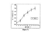
図7aから図7cは、弾性的に変形可能な部材とほぼ図4の構成を持った2つの電源接続点を具備するように変更した、従来の弾性を持った膝サポータを使用して、試行した結果を図で示したものである。 FIGS. 7a to 7c show a trial using a conventional elastic knee supporter modified to include an elastically deformable member and two power connection points having the configuration of FIG. The results are shown in the figure.
図7aは、部材(センサ)の電気抵抗が膝の屈曲の程度の関数であることを示す図である。図7bは、部材の抵抗は部材の有効長の線形関数であることを示す図である。最後に、図7cは、部材の有効長は、膝が曲がっていないとき、約45mmから、膝が110°曲がっているとき、約60mmまで増加することを示す図である。 FIG. 7a is a diagram showing that the electrical resistance of the member (sensor) is a function of the degree of knee flexion. FIG. 7b shows that the resistance of the member is a linear function of the effective length of the member. Finally, FIG. 7c shows that the effective length of the member increases from about 45 mm when the knee is not bent to about 60 mm when the knee is 110 ° bent.
図7aから図7cにて得られた結果は、さらに、膝サポータを装着している人の膝の曲がりを、記録、あるいは、分析に使用できるように、装置を較正するのに使用することができる。さらに、接続点間の部材の有効長は、装置の設計、特に、接続点の互いの位置、さらに、動いているときの形状と構成の変化にも依存していることが理解できるであろう。部材の有効長の電位抵抗は、抵抗部材の選択および部材の伝導特性にも依存している。抵抗特性は、線形であることもできるし、非線形であることもできる。我々の実験のどの場合でも、接続点間で測定された電気抵抗は、10から300kΩの抵抗範囲、そして、適切な範囲は、10から100kΩであることが望ましい。 The results obtained in FIGS. 7a to 7c can also be used to calibrate the device so that the knee bend of the person wearing the knee supporter can be used for recording or analysis. it can. Furthermore, it will be understood that the effective length of the member between the connection points also depends on the design of the device, in particular the position of the connection points relative to each other and also on the shape and configuration changes when moving. . The potential resistance of the effective length of the member also depends on the selection of the resistive member and the conduction characteristics of the member. The resistance characteristic can be linear or non-linear. In any case of our experiments, it is desirable that the electrical resistance measured between the connection points is in the resistance range of 10 to 300 kΩ, and a suitable range is 10 to 100 kΩ.
図8は、1ヘルツの周波数で周期的に直線的に(ほんの少しだけ曲げて)引き伸ばされる、機械的なサイクル応力試験装置に装着した、ルーズ・ニット構造で編んだ部材の電気抵抗を図示したものである。弾性的に変形可能な部材は、ほぼ図1に示した実施態様の構成にした。この例では、測定されて較正の基礎として使用される、曲がり(撓み)の角度の代わりに、図8は、引き伸ばした程度を緩く編んだ繊維スリーブにかけられた応力として測定した結果を示している。 FIG. 8 illustrates the electrical resistance of a member knitted in a loose knitted structure mounted on a mechanical cycle stress testing device that is stretched periodically (bent slightly) at a frequency of 1 Hertz. Is. The elastically deformable member has the configuration of the embodiment shown in FIG. In this example, instead of the angle of bending (deflection) that is measured and used as a basis for calibration, FIG. 8 shows the result of measuring the stretch as a stress applied to a loosely knitted fiber sleeve. .
特に、繊維は、センサが10秒間、最大応力のほぼ20%、30%、および、40%下におかれるように、部分的に伸ばされる。部材の電気抵抗も測定される。図8に示した結果は、屈曲応力センシング用に装置は較正されることができる、選択した数値のセットを提供する。 In particular, the fibers are partially stretched so that the sensor is under approximately 20%, 30%, and 40% of the maximum stress for 10 seconds. The electrical resistance of the member is also measured. The results shown in FIG. 8 provide a selected set of numerical values that can be calibrated for bending stress sensing.
本発明の分野における当業者は、記載した好適な実施態様および実施例は、本発明の範囲と思想を逸脱せずに、多くの変更とバリエーションをなすことができることを理解するであろう。 Those skilled in the art in the field will appreciate that the preferred embodiments and examples described can be varied and varied without departing from the scope and spirit of the invention.
たとえば、人あるいは対象物の動きを検出する、動き検出器あるいは動き検出装置との関連における好適な実施態様で本発明を記載したが、本発明によって検出あるいは監視される動きは、如何なる目的にも使用することができることが理解できるであろう。たとえば、その動きは、トレーニング、あるいは、骨格関節あるいは筋肉損傷のリハビリテーション、生体医療観察、医療用織物、負傷軍人のためのトリアージ・サービス、その他の軍事および警備への応用を目的として、解析されることができる。別の例によれば、この装置は、部材の有効長、したがって、装置の電気抵抗が帆の形状と構成に依存する、ヨットの帆のような媒体に応用できる。換言すると、帆の形状と構成の関数である、帆の風の受け具合とパフォーマンスは、最終的には、この装置によって測定された電気抵抗に基づいて調整される。 For example, although the invention has been described in the preferred embodiment in the context of a motion detector or motion detection device that detects the motion of a person or object, the motion detected or monitored by the present invention is for any purpose. It will be understood that it can be used. For example, the movement is analyzed for training or rehabilitation of skeletal joint or muscle injury, biomedical observation, medical fabrics, triage services for wounded military personnel, and other military and security applications. be able to. According to another example, the device can be applied to a medium such as a sailboat sail, where the effective length of the member, and thus the electrical resistance of the device, depends on the shape and configuration of the sail. In other words, sail wind performance and performance, which is a function of sail shape and configuration, is ultimately adjusted based on the electrical resistance measured by the device.
本発明によって検出された動きの変化は、エレキギターの音のような出力制御にも使用することができる。より具体的には、本発明は、人の肘の動きを監視あるいは検出するように構成することができ、人の肘の動きは、あたかもその人が彼らの手をフレットボードの上に置いた、あるいは、ギターのストリングをかき鳴らしたかのように、人の手の動きを反映する。 The change in motion detected by the present invention can also be used for output control such as the sound of an electric guitar. More specifically, the present invention can be configured to monitor or detect the movement of a person's elbow, which is as if the person placed their hands on the fretboard. Or, it reflects the movement of a person's hand as if it were strumming a guitar string.
加えて、上に述べた好適な実施態様は、部材が、導電性を持ち、かつ、自身の軸を横切る方向に弾性的に変形できる、本質的に、単一の部材である、例である。図には示さないが、案内スティッチ17は、部材を特定の経路に沿って支持して案内する案内構造体で、少なくとも部分的に可能性としては全体的に置き換えられることも考えられる。この案内構造体は、部分的あるいは全体的に部材を取り囲む、チューブ、あるいは、導管の形状をなすことができ、本質的に、非弾性的あるいは弾性的であることができる。案内構造体が非弾性的である場合、好適には、案内構造体は、それを通して最小の摩擦で部材が滑る、チューブ、導管、あるいは、スリーブとして構成されていることが好ましい。案内構造体が弾性的である場合、好適には、案内構造体は、部材の有効長が最小電気抵抗を持つ経路を規定するように、部材の長手方向軸を横切る方向の部材の変形を最小化するように調整されている、チューブ、導管、あるいは、スリーブとして構成されていることが好ましい。部材が織物あるいは基体に埋め込まれている場合も、案内構造体は、織物あるいは基体の中に形成された通路によって提供されることが可能である。全体的なあるいは部分的な織物の弾性的性質によって、部材の変形は最小化される。 In addition, the preferred embodiment described above is an example in which the member is essentially a single member that is conductive and elastically deformable in a direction transverse to its axis. . Although not shown in the figure, it is also conceivable that the guide stitch 17 is a guide structure that supports and guides a member along a particular path and can be at least partially replaced entirely. The guide structure can be in the form of a tube or conduit that partially or wholly surrounds the member and can be essentially inelastic or elastic. Where the guide structure is inelastic, it is preferably configured as a tube, conduit or sleeve through which the member slides with minimal friction. Where the guide structure is elastic, preferably the guide structure minimizes deformation of the member in a direction transverse to the longitudinal axis of the member so that the effective length of the member defines a path with minimal electrical resistance. Preferably, it is configured as a tube, conduit, or sleeve that is adjusted so that Even when the member is embedded in a fabric or substrate, the guide structure can be provided by a passage formed in the fabric or substrate. Due to the overall or partial elastic properties of the fabric, the deformation of the member is minimized.
Claims (54)
a)互いに相対的に運動する、人あるいは対象物の部分に、直接的あるいは間接的に装着できて、使用時に、人あるいは対象物が動いた結果、複数のコネクタ間の間隔が変化することができる、2あるいはそれ以上の収縮器と、
b)細長い電気的部材であって、使用時に、電流を伝導して前記収縮器と電気的に接続され、前記電気的部材の長手方向の軸に沿って実質的に伸張せず、さらに、i)少なくとも部分的に、前記電気的部材の長手方向の軸を横切る方向に弾性的に変形可能、であり、かつ/または、ii)前記電気的部材の有効長が前記収縮器間の最小の電気抵抗を持つ経路を規定して、前記収縮器間の電気抵抗の変化として動きを測定あるいは検出できるように、前記収縮器の相対的な動きが前記収縮器の間の、前記電気的部材の有効長を変化できるように、前記電気的部材の長手方向の軸を横切る方向の変形を最小化するように構成された、弾性的な特性を持つ案内構造体に、直接的にあるいは間接的に支持される、細長い電気的部材と、
を具備する、動きを検出する装置。 A device for detecting movement, for example, but not limited to, movement of a human part, such as a limb or part of a limb,
a) It can be directly or indirectly attached to a part of a person or object that moves relative to each other, and the distance between a plurality of connectors may change as a result of movement of the person or object during use. Two or more contractors,
b) an elongated electrical member that, in use, conducts electrical current and is electrically connected to the contractor, does not substantially extend along the longitudinal axis of the electrical member, and i ) At least partially elastically deformable in a direction transverse to the longitudinal axis of the electrical member and / or ii) the effective length of the electrical member is the smallest electrical between the contractors The relative movement of the constrictor is effective between the constrictors so that movement can be measured or detected as a change in electrical resistance between the constrictors by defining a path with resistance. Directly or indirectly supported by a guide structure with elastic properties configured to minimize the deformation of the electrical member across the longitudinal axis so that the length can be varied An elongated electrical member,
A device for detecting motion, comprising:
a)衣服上の選択した部分に、直接的あるいは間接的に装着されて、衣服がまとわれた時に、人が動いた結果、複数のコネクタ間の間隔が変わることができる、2あるいはそれ以上の収縮器と、
b)細長い電気的部材であって、電源および前記収縮器に接続可能であって、前記電気的部材の長手方向の軸に沿って実質的に伸張せず、さらに、i)少なくとも部分的に、前記電気的部材の長手方向の軸を横切る方向に弾性的に変形可能、であり、かつ/または、ii)前記電気的部材の有効長が収縮器間の最小の電気抵抗を持つ経路を規定して、前記収縮器間の電気抵抗の変化として動きを測定あるいは検出できるように、前記収縮器の相対的な動きが前記収縮器の間の、前記電気的部材の有効長を変化できるように、前記電気的部材の長手方向の軸を横切る方向の変形を最小化するように構成された、弾性的な特性を持つ案内構造体に、直接的にあるいは間接的に支持される、細長い電気的部材と、
を具備する、人の部分の動きを検出する衣服。 Clothing that detects movement of a person's part, such as a person's limb or part of a limb,
a) The distance between a plurality of connectors can be changed as a result of movement of a person when the garment is worn directly or indirectly on a selected part of the garment, and two or more With a contractor,
b) an elongate electrical member, connectable to a power source and the retractor and does not substantially extend along the longitudinal axis of the electrical member; and i) at least partially, Elastically deformable in a direction transverse to the longitudinal axis of the electrical member, and / or ii) the effective length of the electrical member defines a path with minimal electrical resistance between the contractors So that the relative movement of the retractor can change the effective length of the electrical member between the retractors so that movement can be measured or detected as a change in electrical resistance between the retractors. An elongated electrical member supported directly or indirectly by a guide structure having elastic properties, configured to minimize deformation in a direction transverse to the longitudinal axis of the electrical member. When,
A garment for detecting movement of a human part.
Applications Claiming Priority (2)
| Application Number | Priority Date | Filing Date | Title |
|---|---|---|---|
| AU2005905666A AU2005905666A0 (en) | 2005-10-13 | System for detecting movement | |
| PCT/AU2006/001521 WO2007041806A1 (en) | 2005-10-13 | 2006-10-13 | System and garment for detecting movement |
Related Child Applications (1)
| Application Number | Title | Priority Date | Filing Date |
|---|---|---|---|
| JP2013175931A Division JP5536943B2 (en) | 2005-10-13 | 2013-08-27 | Motion detection system |
Publications (2)
| Publication Number | Publication Date |
|---|---|
| JP2009511135A true JP2009511135A (en) | 2009-03-19 |
| JP2009511135A5 JP2009511135A5 (en) | 2012-11-01 |
Family
ID=37942239
Family Applications (2)
| Application Number | Title | Priority Date | Filing Date |
|---|---|---|---|
| JP2008534826A Pending JP2009511135A (en) | 2005-10-13 | 2006-10-13 | Motion detection device and motion detection clothing |
| JP2013175931A Expired - Fee Related JP5536943B2 (en) | 2005-10-13 | 2013-08-27 | Motion detection system |
Family Applications After (1)
| Application Number | Title | Priority Date | Filing Date |
|---|---|---|---|
| JP2013175931A Expired - Fee Related JP5536943B2 (en) | 2005-10-13 | 2013-08-27 | Motion detection system |
Country Status (5)
| Country | Link |
|---|---|
| US (1) | US8291779B2 (en) |
| EP (1) | EP1934551A4 (en) |
| JP (2) | JP2009511135A (en) |
| CN (1) | CN101313194B (en) |
| WO (1) | WO2007041806A1 (en) |
Families Citing this family (22)
| Publication number | Priority date | Publication date | Assignee | Title |
|---|---|---|---|---|
| DE102007044554B3 (en) * | 2007-07-18 | 2009-07-16 | Siemens Ag | Sensor band with optical sensor fiber, sensor with this sensor band and method for calibrating an optical sensor fiber |
| US8696456B2 (en) * | 2009-07-29 | 2014-04-15 | Activision Publishing, Inc. | Music-based video game with user physical performance |
| EP2353505A1 (en) * | 2010-02-03 | 2011-08-10 | Nederlandse Organisatie voor toegepast -natuurwetenschappelijk onderzoek TNO | Method, brace and system for measuring torsion or bending of a part of a human or animal body |
| US8257289B2 (en) | 2010-02-03 | 2012-09-04 | Tyco Healthcare Group Lp | Fitting of compression garment |
| US8648242B2 (en) * | 2010-02-12 | 2014-02-11 | ThinkGeek, Inc. | Interactive electronic apparel incorporating a keyboard image |
| US20120083712A1 (en) | 2010-09-30 | 2012-04-05 | Tyco Healthcare Group Lp | Monitoring Compliance Using Venous Refill Detection |
| US9891718B2 (en) | 2015-04-22 | 2018-02-13 | Medibotics Llc | Devices for measuring finger motion and recognizing hand gestures |
| US9043004B2 (en) | 2012-12-13 | 2015-05-26 | Nike, Inc. | Apparel having sensor system |
| US11892286B2 (en) | 2013-09-17 | 2024-02-06 | Medibotics Llc | Motion recognition clothing [TM] with an electroconductive mesh |
| US11304628B2 (en) | 2013-09-17 | 2022-04-19 | Medibotics Llc | Smart clothing with dual inertial sensors and dual stretch sensors for human motion capture |
| US11071498B2 (en) | 2013-09-17 | 2021-07-27 | Medibotics Llc | Smart clothing with inertial, strain, and electromyographic sensors for human motion capture |
| US9418571B2 (en) | 2013-11-22 | 2016-08-16 | Terry I. Younger | Apparatus and method for training movements to avoid injuries |
| CN103835321B (en) * | 2014-03-14 | 2015-09-02 | 洛阳理工学院 | A kind of easy device for horizontal displacement monitoring |
| SG11201802940YA (en) | 2015-10-09 | 2018-05-30 | Kpr U S Llc | Compression garment compliance |
| US20180310883A1 (en) * | 2015-10-16 | 2018-11-01 | Wearable Technologies Pty Ltd | Method and device for recording movement in a continuous area |
| US10577732B1 (en) | 2016-02-26 | 2020-03-03 | Apple Inc. | Knit fabric with electrical components |
| CN105865594B (en) * | 2016-05-30 | 2023-12-22 | 电子科技大学中山学院 | Weighing device |
| US9819122B1 (en) * | 2016-06-29 | 2017-11-14 | Intel Corporation | Apparel compute device connection |
| DE102017111099B3 (en) * | 2017-05-22 | 2018-06-07 | Otto Bock Healthcare Gmbh | Method and device for determining a mechanical load |
| US10180721B2 (en) * | 2017-06-14 | 2019-01-15 | Apple Inc. | Fabric-based devices with force sensing |
| CN109183219B (en) * | 2018-08-01 | 2021-04-16 | 盐城工学院 | Intelligent yarn switch sensor |
| IT202000018331A1 (en) * | 2020-07-28 | 2022-01-28 | Koyre S R L | STRESS DETECTION SYSTEM IN A FLEXIBLE TWO-DIMENSIONAL STRUCTURE |
Citations (7)
| Publication number | Priority date | Publication date | Assignee | Title |
|---|---|---|---|---|
| JPS61201045A (en) * | 1985-03-04 | 1986-09-05 | 旭化成株式会社 | Deformed conductive knitted cloth |
| JPS61259103A (en) * | 1985-05-14 | 1986-11-17 | Asahi Chem Ind Co Ltd | Sensor element |
| JPS6276601A (en) * | 1985-09-30 | 1987-04-08 | 旭化成株式会社 | Elongated conductive structure |
| JPS6276602A (en) * | 1985-09-30 | 1987-04-08 | 旭化成株式会社 | Elongated conductive cloth piece |
| US4715235A (en) * | 1985-03-04 | 1987-12-29 | Asahi Kasei Kogyo Kabushiki Kaisha | Deformation sensitive electroconductive knitted or woven fabric and deformation sensitive electroconductive device comprising the same |
| US5086785A (en) * | 1989-08-10 | 1992-02-11 | Abrams/Gentille Entertainment Inc. | Angular displacement sensors |
| WO2003060449A1 (en) * | 2002-01-03 | 2003-07-24 | Technoskin, Llc | An signal-emitting fabric strain gauge device |
Family Cites Families (18)
| Publication number | Priority date | Publication date | Assignee | Title |
|---|---|---|---|---|
| US3908279A (en) * | 1973-08-29 | 1975-09-30 | Wilmark Electronic Co | Curvature measurement device |
| US4108164A (en) * | 1976-10-01 | 1978-08-22 | Hall Sr Henry W | Standard bending profile jacket |
| DK38388A (en) | 1988-01-27 | 1989-06-06 | Doublet Record A S | EARTHWORKING EQUIPMENT AND POSITION SENSOR FOR USE HERE |
| US5047952A (en) * | 1988-10-14 | 1991-09-10 | The Board Of Trustee Of The Leland Stanford Junior University | Communication system for deaf, deaf-blind, or non-vocal individuals using instrumented glove |
| US5052375A (en) * | 1990-02-21 | 1991-10-01 | John G. Stark | Instrumented orthopedic restraining device and method of use |
| US5166463A (en) * | 1991-10-21 | 1992-11-24 | Steven Weber | Motion orchestration system |
| DE4329898A1 (en) * | 1993-09-04 | 1995-04-06 | Marcus Dr Besson | Wireless medical diagnostic and monitoring device |
| US6032530A (en) * | 1994-04-29 | 2000-03-07 | Advantedge Systems Inc. | Biofeedback system for sensing body motion and flexure |
| US5570301A (en) * | 1994-07-15 | 1996-10-29 | Mitsubishi Electric Information Technology Center America, Inc. | System for unencumbered measurement and reporting of body posture |
| US5930741A (en) * | 1995-02-28 | 1999-07-27 | Virtual Technologies, Inc. | Accurate, rapid, reliable position sensing using multiple sensing technologies |
| AU7161598A (en) * | 1997-04-21 | 1998-11-13 | Virtual Technologies, Inc. | Goniometer-based body-tracking device and method |
| US6119516A (en) * | 1997-05-23 | 2000-09-19 | Advantedge Systems, Inc. | Biofeedback system for monitoring the motion of body joint |
| JP4446263B2 (en) * | 1997-10-09 | 2010-04-07 | ボウルドン−ヘンニ・ホールデイング・アクチエンゲゼルシヤフト | Force sensor |
| US5980472A (en) * | 1998-02-20 | 1999-11-09 | Seyl; V. Craig | Joint movement monitoring system |
| US6486906B1 (en) * | 2000-09-13 | 2002-11-26 | Lexmark International, Inc. | Apparatus and method for printhead to machine skew and margin adjustment for an electrophotographic machine |
| US6487906B1 (en) | 2000-09-18 | 2002-12-03 | Advantedge Systems Inc | Flexible film sensor system for monitoring body motion |
| AUPR694401A0 (en) * | 2001-08-10 | 2001-09-06 | University Of Wollongong, The | Bio-mechanical feedback device |
| US7559902B2 (en) * | 2003-08-22 | 2009-07-14 | Foster-Miller, Inc. | Physiological monitoring garment |
-
2006
- 2006-10-13 US US12/089,786 patent/US8291779B2/en not_active Expired - Fee Related
- 2006-10-13 EP EP06790386A patent/EP1934551A4/en not_active Withdrawn
- 2006-10-13 WO PCT/AU2006/001521 patent/WO2007041806A1/en active Application Filing
- 2006-10-13 CN CN2006800435219A patent/CN101313194B/en not_active Expired - Fee Related
- 2006-10-13 JP JP2008534826A patent/JP2009511135A/en active Pending
-
2013
- 2013-08-27 JP JP2013175931A patent/JP5536943B2/en not_active Expired - Fee Related
Patent Citations (7)
| Publication number | Priority date | Publication date | Assignee | Title |
|---|---|---|---|---|
| JPS61201045A (en) * | 1985-03-04 | 1986-09-05 | 旭化成株式会社 | Deformed conductive knitted cloth |
| US4715235A (en) * | 1985-03-04 | 1987-12-29 | Asahi Kasei Kogyo Kabushiki Kaisha | Deformation sensitive electroconductive knitted or woven fabric and deformation sensitive electroconductive device comprising the same |
| JPS61259103A (en) * | 1985-05-14 | 1986-11-17 | Asahi Chem Ind Co Ltd | Sensor element |
| JPS6276601A (en) * | 1985-09-30 | 1987-04-08 | 旭化成株式会社 | Elongated conductive structure |
| JPS6276602A (en) * | 1985-09-30 | 1987-04-08 | 旭化成株式会社 | Elongated conductive cloth piece |
| US5086785A (en) * | 1989-08-10 | 1992-02-11 | Abrams/Gentille Entertainment Inc. | Angular displacement sensors |
| WO2003060449A1 (en) * | 2002-01-03 | 2003-07-24 | Technoskin, Llc | An signal-emitting fabric strain gauge device |
Also Published As
| Publication number | Publication date |
|---|---|
| CN101313194B (en) | 2010-09-08 |
| US20090095094A1 (en) | 2009-04-16 |
| CN101313194A (en) | 2008-11-26 |
| EP1934551A1 (en) | 2008-06-25 |
| JP5536943B2 (en) | 2014-07-02 |
| WO2007041806A1 (en) | 2007-04-19 |
| EP1934551A4 (en) | 2009-12-30 |
| JP2013248528A (en) | 2013-12-12 |
| US8291779B2 (en) | 2012-10-23 |
Similar Documents
| Publication | Publication Date | Title |
|---|---|---|
| JP5536943B2 (en) | Motion detection system | |
| JP2009511135A5 (en) | ||
| Yuen et al. | Conformable actuation and sensing with robotic fabric | |
| US20080139969A1 (en) | Fabric Sensor and a Garmet Incorporating the Sensor | |
| Abro et al. | Development of a smart garment for monitoring body postures based on FBG and flex sensing technologies | |
| US20120197160A1 (en) | Device for detecting and/or influencing posture | |
| JP5432513B2 (en) | Biological signal measuring device | |
| JP2019535438A (en) | Device and method for muscular support | |
| US20200405195A1 (en) | Computational fabrics for monitoring human joint motion | |
| US20200330002A1 (en) | Piezoelectric patch sensor | |
| JP6706747B2 (en) | Strain measuring sensor | |
| WO2021192737A1 (en) | Motion detection system | |
| KR102060678B1 (en) | Wearable strain sensor | |
| JP7240753B2 (en) | Clothing, measurement equipment, and monitoring systems | |
| EP4130937A1 (en) | Motion-detecting member | |
| AU2006301871B2 (en) | System and garment for detecting movement | |
| US20230151514A1 (en) | Hysteresis in textile sensor | |
| TWI483707B (en) | Wear - type respiratory physiological measurement device | |
| Gibbs et al. | Wearable conductive fiber sensor arrays for measuring multi-axis joint motion | |
| Dupler | Characterizing the influence of the textile-sensor interface on stitched sensor performance | |
| US20240049992A1 (en) | Elongation sensor and wearable article including the elongation sensor | |
| US20240130678A1 (en) | Textile configured for strain sensing, method of manufacturing a textile for strain sensing and a knitting apparatus thereof | |
| JP2024053454A (en) | Communication System | |
| JP2024512270A (en) | Textile configured for strain detection, method for manufacturing textile for strain detection, and knitting device thereof | |
| Gibbs | Design and analysis of wearable conductive fiber sensors for continuous multi-axis joint angle measurements |
Legal Events
| Date | Code | Title | Description |
|---|---|---|---|
| A521 | Written amendment |
Free format text: JAPANESE INTERMEDIATE CODE: A523 Effective date: 20091013 |
|
| A621 | Written request for application examination |
Free format text: JAPANESE INTERMEDIATE CODE: A621 Effective date: 20091013 |
|
| A131 | Notification of reasons for refusal |
Free format text: JAPANESE INTERMEDIATE CODE: A131 Effective date: 20120306 |
|
| A601 | Written request for extension of time |
Free format text: JAPANESE INTERMEDIATE CODE: A601 Effective date: 20120605 |
|
| A602 | Written permission of extension of time |
Free format text: JAPANESE INTERMEDIATE CODE: A602 Effective date: 20120612 |
|
| A524 | Written submission of copy of amendment under section 19 (pct) |
Free format text: JAPANESE INTERMEDIATE CODE: A524 Effective date: 20120831 |
|
| A521 | Written amendment |
Free format text: JAPANESE INTERMEDIATE CODE: A523 Effective date: 20120903 |
|
| A521 | Written amendment |
Free format text: JAPANESE INTERMEDIATE CODE: A523 Effective date: 20120911 |
|
| A131 | Notification of reasons for refusal |
Free format text: JAPANESE INTERMEDIATE CODE: A131 Effective date: 20130416 |
|
| A601 | Written request for extension of time |
Free format text: JAPANESE INTERMEDIATE CODE: A601 Effective date: 20130712 |
|
| A602 | Written permission of extension of time |
Free format text: JAPANESE INTERMEDIATE CODE: A602 Effective date: 20130722 |
|
| A02 | Decision of refusal |
Free format text: JAPANESE INTERMEDIATE CODE: A02 Effective date: 20140107 |