EP4130937A1 - Motion-detecting member - Google Patents
Motion-detecting member Download PDFInfo
- Publication number
- EP4130937A1 EP4130937A1 EP21774079.4A EP21774079A EP4130937A1 EP 4130937 A1 EP4130937 A1 EP 4130937A1 EP 21774079 A EP21774079 A EP 21774079A EP 4130937 A1 EP4130937 A1 EP 4130937A1
- Authority
- EP
- European Patent Office
- Prior art keywords
- wiring part
- wearable
- wiring
- expanding
- electrode
- Prior art date
- Legal status (The legal status is an assumption and is not a legal conclusion. Google has not performed a legal analysis and makes no representation as to the accuracy of the status listed.)
- Pending
Links
- 238000001514 detection method Methods 0.000 claims abstract description 341
- 230000033001 locomotion Effects 0.000 claims abstract description 149
- 239000004744 fabric Substances 0.000 claims abstract description 115
- 239000000463 material Substances 0.000 claims abstract description 115
- OKTJSMMVPCPJKN-UHFFFAOYSA-N Carbon Chemical compound [C] OKTJSMMVPCPJKN-UHFFFAOYSA-N 0.000 claims description 52
- 239000002041 carbon nanotube Substances 0.000 claims description 47
- 229910021393 carbon nanotube Inorganic materials 0.000 claims description 47
- 230000008859 change Effects 0.000 claims description 33
- 210000001503 joint Anatomy 0.000 claims description 16
- 230000007423 decrease Effects 0.000 claims description 9
- 210000000811 metacarpophalangeal joint Anatomy 0.000 claims description 5
- 210000003811 finger Anatomy 0.000 description 84
- 229910052751 metal Inorganic materials 0.000 description 29
- 239000002184 metal Substances 0.000 description 29
- 230000004048 modification Effects 0.000 description 23
- 238000012986 modification Methods 0.000 description 23
- 238000004891 communication Methods 0.000 description 16
- 239000002131 composite material Substances 0.000 description 16
- 230000008602 contraction Effects 0.000 description 14
- 238000009940 knitting Methods 0.000 description 14
- 210000003813 thumb Anatomy 0.000 description 13
- PXHVJJICTQNCMI-UHFFFAOYSA-N Nickel Chemical compound [Ni] PXHVJJICTQNCMI-UHFFFAOYSA-N 0.000 description 10
- 238000005452 bending Methods 0.000 description 10
- 239000000835 fiber Substances 0.000 description 10
- 210000004932 little finger Anatomy 0.000 description 10
- 210000000707 wrist Anatomy 0.000 description 10
- BQCADISMDOOEFD-UHFFFAOYSA-N Silver Chemical compound [Ag] BQCADISMDOOEFD-UHFFFAOYSA-N 0.000 description 8
- 229910052709 silver Inorganic materials 0.000 description 8
- 239000004332 silver Substances 0.000 description 8
- 238000005259 measurement Methods 0.000 description 7
- 239000002759 woven fabric Substances 0.000 description 7
- 239000011347 resin Substances 0.000 description 6
- 229920005989 resin Polymers 0.000 description 6
- 229910001092 metal group alloy Inorganic materials 0.000 description 5
- 238000000034 method Methods 0.000 description 5
- 229910052759 nickel Inorganic materials 0.000 description 5
- 238000009958 sewing Methods 0.000 description 5
- XMWRBQBLMFGWIX-UHFFFAOYSA-N C60 fullerene Chemical compound C12=C3C(C4=C56)=C7C8=C5C5=C9C%10=C6C6=C4C1=C1C4=C6C6=C%10C%10=C9C9=C%11C5=C8C5=C8C7=C3C3=C7C2=C1C1=C2C4=C6C4=C%10C6=C9C9=C%11C5=C5C8=C3C3=C7C1=C1C2=C4C6=C2C9=C5C3=C12 XMWRBQBLMFGWIX-UHFFFAOYSA-N 0.000 description 4
- RYGMFSIKBFXOCR-UHFFFAOYSA-N Copper Chemical compound [Cu] RYGMFSIKBFXOCR-UHFFFAOYSA-N 0.000 description 4
- XEEYBQQBJWHFJM-UHFFFAOYSA-N Iron Chemical compound [Fe] XEEYBQQBJWHFJM-UHFFFAOYSA-N 0.000 description 4
- 239000003575 carbonaceous material Substances 0.000 description 4
- 229910052802 copper Inorganic materials 0.000 description 4
- 239000010949 copper Substances 0.000 description 4
- 238000010586 diagram Methods 0.000 description 4
- 210000003127 knee Anatomy 0.000 description 4
- 150000002739 metals Chemical class 0.000 description 4
- 238000009941 weaving Methods 0.000 description 4
- 239000000853 adhesive Substances 0.000 description 3
- 230000001070 adhesive effect Effects 0.000 description 3
- 239000004020 conductor Substances 0.000 description 3
- 210000004177 elastic tissue Anatomy 0.000 description 3
- 238000009956 embroidering Methods 0.000 description 3
- 239000010985 leather Substances 0.000 description 3
- 238000004519 manufacturing process Methods 0.000 description 3
- 229910044991 metal oxide Inorganic materials 0.000 description 3
- 150000004706 metal oxides Chemical class 0.000 description 3
- 239000000123 paper Substances 0.000 description 3
- -1 polypropylene Polymers 0.000 description 3
- 229910000679 solder Inorganic materials 0.000 description 3
- 229920000049 Carbon (fiber) Polymers 0.000 description 2
- VYZAMTAEIAYCRO-UHFFFAOYSA-N Chromium Chemical compound [Cr] VYZAMTAEIAYCRO-UHFFFAOYSA-N 0.000 description 2
- 239000004952 Polyamide Substances 0.000 description 2
- ATJFFYVFTNAWJD-UHFFFAOYSA-N Tin Chemical compound [Sn] ATJFFYVFTNAWJD-UHFFFAOYSA-N 0.000 description 2
- HCHKCACWOHOZIP-UHFFFAOYSA-N Zinc Chemical compound [Zn] HCHKCACWOHOZIP-UHFFFAOYSA-N 0.000 description 2
- 229910045601 alloy Inorganic materials 0.000 description 2
- 239000000956 alloy Substances 0.000 description 2
- 229910052782 aluminium Inorganic materials 0.000 description 2
- XAGFODPZIPBFFR-UHFFFAOYSA-N aluminium Chemical compound [Al] XAGFODPZIPBFFR-UHFFFAOYSA-N 0.000 description 2
- 210000003423 ankle Anatomy 0.000 description 2
- 230000008901 benefit Effects 0.000 description 2
- 239000004917 carbon fiber Substances 0.000 description 2
- 229910052804 chromium Inorganic materials 0.000 description 2
- 239000011651 chromium Substances 0.000 description 2
- 229920001940 conductive polymer Polymers 0.000 description 2
- 230000007797 corrosion Effects 0.000 description 2
- 238000005260 corrosion Methods 0.000 description 2
- 238000002788 crimping Methods 0.000 description 2
- 210000001513 elbow Anatomy 0.000 description 2
- 230000001747 exhibiting effect Effects 0.000 description 2
- 210000002683 foot Anatomy 0.000 description 2
- PCHJSUWPFVWCPO-UHFFFAOYSA-N gold Chemical compound [Au] PCHJSUWPFVWCPO-UHFFFAOYSA-N 0.000 description 2
- 229910052737 gold Inorganic materials 0.000 description 2
- 239000010931 gold Substances 0.000 description 2
- 229910021389 graphene Inorganic materials 0.000 description 2
- 210000001624 hip Anatomy 0.000 description 2
- 238000009413 insulation Methods 0.000 description 2
- 229910052742 iron Inorganic materials 0.000 description 2
- VNWKTOKETHGBQD-UHFFFAOYSA-N methane Chemical compound C VNWKTOKETHGBQD-UHFFFAOYSA-N 0.000 description 2
- 238000007747 plating Methods 0.000 description 2
- 229920002647 polyamide Polymers 0.000 description 2
- 229920000728 polyester Polymers 0.000 description 2
- 238000009987 spinning Methods 0.000 description 2
- 239000000758 substrate Substances 0.000 description 2
- 229910052718 tin Inorganic materials 0.000 description 2
- 239000011135 tin Substances 0.000 description 2
- 229910052725 zinc Inorganic materials 0.000 description 2
- 239000011701 zinc Substances 0.000 description 2
- 229920002972 Acrylic fiber Polymers 0.000 description 1
- 229910001369 Brass Inorganic materials 0.000 description 1
- 229910000906 Bronze Inorganic materials 0.000 description 1
- 244000025254 Cannabis sativa Species 0.000 description 1
- 235000012766 Cannabis sativa ssp. sativa var. sativa Nutrition 0.000 description 1
- 235000012765 Cannabis sativa ssp. sativa var. spontanea Nutrition 0.000 description 1
- 229910000975 Carbon steel Inorganic materials 0.000 description 1
- 229920000742 Cotton Polymers 0.000 description 1
- 229910000881 Cu alloy Inorganic materials 0.000 description 1
- JOYRKODLDBILNP-UHFFFAOYSA-N Ethyl urethane Chemical compound CCOC(N)=O JOYRKODLDBILNP-UHFFFAOYSA-N 0.000 description 1
- ZOKXTWBITQBERF-UHFFFAOYSA-N Molybdenum Chemical compound [Mo] ZOKXTWBITQBERF-UHFFFAOYSA-N 0.000 description 1
- 229910001096 P alloy Inorganic materials 0.000 description 1
- OAICVXFJPJFONN-UHFFFAOYSA-N Phosphorus Chemical compound [P] OAICVXFJPJFONN-UHFFFAOYSA-N 0.000 description 1
- 239000004743 Polypropylene Substances 0.000 description 1
- 229920000297 Rayon Polymers 0.000 description 1
- 229910000831 Steel Inorganic materials 0.000 description 1
- RTAQQCXQSZGOHL-UHFFFAOYSA-N Titanium Chemical compound [Ti] RTAQQCXQSZGOHL-UHFFFAOYSA-N 0.000 description 1
- 229910001297 Zn alloy Inorganic materials 0.000 description 1
- SNDJECPQBZAXEZ-UHFFFAOYSA-N [P].[Fe].[Zn].[Cu] Chemical compound [P].[Fe].[Zn].[Cu] SNDJECPQBZAXEZ-UHFFFAOYSA-N 0.000 description 1
- JUWOETZNAMLKMG-UHFFFAOYSA-N [P].[Ni].[Cu] Chemical compound [P].[Ni].[Cu] JUWOETZNAMLKMG-UHFFFAOYSA-N 0.000 description 1
- HZEWFHLRYVTOIW-UHFFFAOYSA-N [Ti].[Ni] Chemical compound [Ti].[Ni] HZEWFHLRYVTOIW-UHFFFAOYSA-N 0.000 description 1
- 230000009471 action Effects 0.000 description 1
- 229910003481 amorphous carbon Inorganic materials 0.000 description 1
- DMFGNRRURHSENX-UHFFFAOYSA-N beryllium copper Chemical compound [Be].[Cu] DMFGNRRURHSENX-UHFFFAOYSA-N 0.000 description 1
- 239000010951 brass Substances 0.000 description 1
- 239000010974 bronze Substances 0.000 description 1
- 235000009120 camo Nutrition 0.000 description 1
- 239000006229 carbon black Substances 0.000 description 1
- 239000011852 carbon nanoparticle Substances 0.000 description 1
- 239000010962 carbon steel Substances 0.000 description 1
- 235000005607 chanvre indien Nutrition 0.000 description 1
- KUNSUQLRTQLHQQ-UHFFFAOYSA-N copper tin Chemical compound [Cu].[Sn] KUNSUQLRTQLHQQ-UHFFFAOYSA-N 0.000 description 1
- XTYUEDCPRIMJNG-UHFFFAOYSA-N copper zirconium Chemical compound [Cu].[Zr] XTYUEDCPRIMJNG-UHFFFAOYSA-N 0.000 description 1
- 230000003247 decreasing effect Effects 0.000 description 1
- 239000006185 dispersion Substances 0.000 description 1
- 230000000694 effects Effects 0.000 description 1
- 239000010419 fine particle Substances 0.000 description 1
- 210000001145 finger joint Anatomy 0.000 description 1
- 229910003472 fullerene Inorganic materials 0.000 description 1
- 229910002804 graphite Inorganic materials 0.000 description 1
- 239000010439 graphite Substances 0.000 description 1
- 229910021385 hard carbon Inorganic materials 0.000 description 1
- 229910000856 hastalloy Inorganic materials 0.000 description 1
- 239000011487 hemp Substances 0.000 description 1
- 238000007733 ion plating Methods 0.000 description 1
- UGKDIUIOSMUOAW-UHFFFAOYSA-N iron nickel Chemical compound [Fe].[Ni] UGKDIUIOSMUOAW-UHFFFAOYSA-N 0.000 description 1
- 229910000953 kanthal Inorganic materials 0.000 description 1
- 239000007788 liquid Substances 0.000 description 1
- 230000007257 malfunction Effects 0.000 description 1
- 229910052750 molybdenum Inorganic materials 0.000 description 1
- 239000011733 molybdenum Substances 0.000 description 1
- 210000003739 neck Anatomy 0.000 description 1
- 229910001120 nichrome Inorganic materials 0.000 description 1
- 229910001000 nickel titanium Inorganic materials 0.000 description 1
- 229910000623 nickel–chromium alloy Inorganic materials 0.000 description 1
- 239000004745 nonwoven fabric Substances 0.000 description 1
- 229920000642 polymer Polymers 0.000 description 1
- 229920001155 polypropylene Polymers 0.000 description 1
- 229920002635 polyurethane Polymers 0.000 description 1
- 239000004814 polyurethane Substances 0.000 description 1
- 230000008569 process Effects 0.000 description 1
- 239000002964 rayon Substances 0.000 description 1
- DECCZIUVGMLHKQ-UHFFFAOYSA-N rhenium tungsten Chemical compound [W].[Re] DECCZIUVGMLHKQ-UHFFFAOYSA-N 0.000 description 1
- 239000011435 rock Substances 0.000 description 1
- 238000000926 separation method Methods 0.000 description 1
- 210000002832 shoulder Anatomy 0.000 description 1
- 229920002379 silicone rubber Polymers 0.000 description 1
- 239000004945 silicone rubber Substances 0.000 description 1
- 238000009751 slip forming Methods 0.000 description 1
- 229910021384 soft carbon Inorganic materials 0.000 description 1
- 238000004544 sputter deposition Methods 0.000 description 1
- 239000010935 stainless steel Substances 0.000 description 1
- 229910001220 stainless steel Inorganic materials 0.000 description 1
- 239000010959 steel Substances 0.000 description 1
- 229920002994 synthetic fiber Polymers 0.000 description 1
- 239000012209 synthetic fiber Substances 0.000 description 1
- 229910052719 titanium Inorganic materials 0.000 description 1
- 239000010936 titanium Substances 0.000 description 1
- WFKWXMTUELFFGS-UHFFFAOYSA-N tungsten Chemical compound [W] WFKWXMTUELFFGS-UHFFFAOYSA-N 0.000 description 1
- 229910052721 tungsten Inorganic materials 0.000 description 1
- 239000010937 tungsten Substances 0.000 description 1
- 238000007740 vapor deposition Methods 0.000 description 1
- 238000004078 waterproofing Methods 0.000 description 1
- 210000002268 wool Anatomy 0.000 description 1
Images


Classifications
-
- G—PHYSICS
- G01—MEASURING; TESTING
- G01B—MEASURING LENGTH, THICKNESS OR SIMILAR LINEAR DIMENSIONS; MEASURING ANGLES; MEASURING AREAS; MEASURING IRREGULARITIES OF SURFACES OR CONTOURS
- G01B7/00—Measuring arrangements characterised by the use of electric or magnetic techniques
- G01B7/16—Measuring arrangements characterised by the use of electric or magnetic techniques for measuring the deformation in a solid, e.g. by resistance strain gauge
- G01B7/18—Measuring arrangements characterised by the use of electric or magnetic techniques for measuring the deformation in a solid, e.g. by resistance strain gauge using change in resistance
-
- A—HUMAN NECESSITIES
- A61—MEDICAL OR VETERINARY SCIENCE; HYGIENE
- A61B—DIAGNOSIS; SURGERY; IDENTIFICATION
- A61B5/00—Measuring for diagnostic purposes; Identification of persons
- A61B5/103—Detecting, measuring or recording devices for testing the shape, pattern, colour, size or movement of the body or parts thereof, for diagnostic purposes
- A61B5/11—Measuring movement of the entire body or parts thereof, e.g. head or hand tremor, mobility of a limb
-
- A—HUMAN NECESSITIES
- A61—MEDICAL OR VETERINARY SCIENCE; HYGIENE
- A61B—DIAGNOSIS; SURGERY; IDENTIFICATION
- A61B5/00—Measuring for diagnostic purposes; Identification of persons
- A61B5/68—Arrangements of detecting, measuring or recording means, e.g. sensors, in relation to patient
- A61B5/6801—Arrangements of detecting, measuring or recording means, e.g. sensors, in relation to patient specially adapted to be attached to or worn on the body surface
- A61B5/6802—Sensor mounted on worn items
- A61B5/6804—Garments; Clothes
- A61B5/6806—Gloves
-
- G—PHYSICS
- G06—COMPUTING; CALCULATING OR COUNTING
- G06F—ELECTRIC DIGITAL DATA PROCESSING
- G06F3/00—Input arrangements for transferring data to be processed into a form capable of being handled by the computer; Output arrangements for transferring data from processing unit to output unit, e.g. interface arrangements
- G06F3/01—Input arrangements or combined input and output arrangements for interaction between user and computer
- G06F3/011—Arrangements for interaction with the human body, e.g. for user immersion in virtual reality
- G06F3/014—Hand-worn input/output arrangements, e.g. data gloves
Definitions
- the present disclosure relates to a motion detection member.
- a motion detection member for detecting the motion of human body parts such as an elbow, knee, waist, or finger
- human body parts such as an elbow, knee, waist, or finger
- JP-A Japanese Patent Application Laid-Open
- JP-A No. 2016-130940 discloses "a glove-type input device to be worn on a hand to detect the motion or the shape of the hand of a user, the glove-type input device including a sensing device for detecting motion of a finger joint formed by using an expandable/contractible conductive ink at an outer side and/or an inner side of a glove configured from a material capable of expanding/contracting".
- JP-ANo. 2017-061770 discloses "a glove equipped with a strain sensor, the glove comprising: a glove main body that can be worn on a hand of a wearer; one or a plurality of sheet-shaped strain sensors that are provided at a joint-corresponding portion other than a surface at the palm side of the glove main body and that expand/contract so as to follow deformation of the glove main body; and an expandable/contractible wiring part that is provided integrally with the glove main body so as to deform and follow the deformation of the glove main body.
- the detection part that detects the motion is formed using an expandable/contractible conductive ink. Therefore, durability is low.
- the detection part that detects the motion includes a resin film (a film of a resin such as a silicone rubber or a urethane) as a base material. Therefore, the portion having the detection part may make a user feel uncomfortable, when wearing the motion detection member, due to the presence of the base material.
- a resin film a film of a resin such as a silicone rubber or a urethane
- an object of the present disclosure is to provide a motion detection member that is highly durable and comfortable to wear.
- a numerical range using "to” signifies a numerical range in which the numerical values indicated before and after "to” are included as a minimum value and a maximum value, respectively.
- an upper limit value or a lower limit value described in one numerical range may be replaced with an upper limit value or a lower limit value of another numerical range described in stages.
- the motion detection member according to the present embodiment is a member for detecting the motion of a wearing body.
- the expanding/contracting portion expands/contracts (that is, expands and contracts) as a result of motion of the wearing body
- a contact state between the first wiring part and the second wiring part changes, so that a resistance value between the first electrode part and the second electrode part changes.
- the wiring electrode part for detecting motion is configured from a conductive linear body. Therefore, durability is also high.
- a wiring part configured from a conductive linear body is provided at an expanding/contracting portion of the wearable part configured from an expandable/contractible fabric material. Therefore, discomfort is not readily felt when the motion detection member is worn on the wearing body, and the wearing feeling is excellent.
- the glove-type input device, the glove equipped with a strain sensor, and the like, of JP-ANo. 2016-130940 require calibration in a state where a hand is open and a state where the hand is closed, and if the glove is continuously used, a sensor position is shifted, and there is a possibility of detection accuracy being reduced.
- the motion detection member according to the present embodiment does not require calibration, can be used immediately after wearing, and has a wide permissible range of positional deviation.
- the resistance value between the first electrode part and the second electrode part changes indicates that 1) the resistance value increases or decreases while the state between the first electrode part and the second electrode part is a conductive state, or that 2) the state between the first electrode part and the second electrode part changes from a conductive state to a non-conductive state or from a non-conductive state to a conductive state. Note that the change in the resistance value does not include a change in the resistance value due to damage of the electrode part, the wiring part, or the junction between the electrode part and the wiring part.
- the phrase "at least a portion of the first wiring part and at least a portion of the second wiring part are in contact with each other” may also include an embodiment in which, in a case in which another wiring part other than the first wiring part or the second wiring part (for example, a third wiring part) is included, at least a portion of the first wiring part and at least a portion of the second wiring part are in contact with each other via the other wiring part.
- another wiring part other than the first wiring part or the second wiring part for example, a third wiring part
- the wiring part is provided at the expanding/contracting portion indicates that "the wiring part is provided at the surface of an expandable/contractible fabric material" or "the wiring part is provided inside the expandable/contractible fabric material”.
- the wiring part is provided at the surface of the expandable/contractible fabric material indicates that the wiring part (that is, the conductive linear body) is provided at a fabric material layer that constitutes the front or back surface of the expandable/contractible fabric material (which may also be a fabric material layer partially constituting the front or back surface).
- the wiring part is provided at the surface of the expandable/contractible fabric material indicates that the electrode part or the wiring part (that is, the conductive linear body) is provided in a state where at least a portion of the conductive linear body constituting the wiring part is exposed from the expandable/contractible fabric material.
- the wiring part is provided inside the expandable/contractible fabric material
- the wiring part that is, the conductive linear body
- the wiring part is provided at the inner layer of the expandable/contractible fabric material, for example, in the fabric material layer serving as the inner layer of the expandable/contractible fabric material or between the fabric material layers.
- the wearable part includes an expanding/contracting portion configured from an expandable/contractible fabric material
- examples of the method of providing the expanding/contracting portion include bonding using an adhesive, attachment by sewing, and the like.
- the motion detection member includes, for example, both an embodiment in which a wiring part is provided at a position corresponding to the expanding/contracting portion of the wearable part that is configured from a fabric material or the like (such as a glove or a wristband), and an embodiment in which an expandable/contractible fabric material having a wiring part is separately bonded to the surface at a position corresponding to the expanding/contracting portion of a conventional wearable part (such as a glove or a wristband) configured from a known material such as a fabric material, a resin, paper, or leather.
- a fabric material or the like such as a glove or a wristband
- an expandable/contractible fabric material having a wiring part is separately bonded to the surface at a position corresponding to the expanding/contracting portion of a conventional wearable part (such as a glove or a wristband) configured from a known material such as a fabric material, a resin, paper, or leather.
- a motion detection member 150 according to the present embodiment is a glove-shaped member as illustrated in Fig. 1 .
- the motion detection member 150 includes, for example, a glove-shaped wearable part 10 (an example of a wearable part), a wiring electrode part 100, and a communication module 202.
- the glove-shaped wearable part 10 is a glove-shaped wearable part that is to be worn on a hand of a human body serving as a wearing body.
- the glove-shaped wearable part 10 includes a wrist part 1 to be worn on a wrist of a human body, a finger part 2 to be worn on a finger of the human body, and a body part 3 connecting the wrist part 1 and the finger part 2.
- the wrist part 1, a connecting part connecting the finger part 2 and the body part 3 (a portion corresponding to the metacarpophalangeal joint), and the finger part 2 (a portion corresponding to the distal interphalangeal joint and the proximal interphalangeal joint) corresponds to an example of the "expanding/contracting portion that expands/contracts as a result of motion of the wearing body".
- a portion of the finger part 2 facing the dorsal side of the proximal interphalangeal joint corresponds to an example of the "expanding/contracting portion of the wearable part, at which the wiring part is provided".
- the glove-shaped wearable part 10 includes, for example, five finger parts 2 corresponding to respective fingers.
- the glove-shaped wearable part 10 has, as the finger parts 2, for example, a thumb part 2Athat is to be worn on the thumb, an index finger part 2B that is to be worn on the index finger, a middle finger part 2C that is to be worn on the middle finger, a ring finger part 2D that is to be worn on the ring finger, and a little finger part 2E that is to be worn on the little finger.
- the glove-shaped wearable part 10 may include, as the finger part 2, for example, two portions, namely, a thumb part that is to be worn on the thumb, and a finger part that is to be worn on the index finger, the middle finger, the ring finger, and the little finger.
- the glove-shaped wearable part 10 is configured, for example, from triple (three layers of) fabric material layers, namely, a front surface fabric material layer 10A constituting a front surface, a back surface fabric material layer 10B constituting a back surface, and an intermediate fabric material layer 10C provided between the front surface fabric material layer 10A and the back surface fabric material layer 10B.
- the glove-shaped wearable part 10 may be configured, for example, from one (single) fabric material layer, or from double (two) or quadruple (four) fabric material layers or more instead of the triple fabric material layers.
- multi-layer wearable part configured from two or more fabric material layers may be manufactured by, for example, a method of manufacturing respective fabric material layers and then sewing them together, or the multi-layer glove-shaped wearable part 10 may be collectively manufactured by a weaving or knitting machine.
- the glove-shaped wearable part 10 is configured from an expandable/contractible fabric material, for example.
- Typical examples of the expandable/contractible fabric material are woven or knitted fabrics.
- the glove-shaped wearable part 10 may also be a nonwoven fabric.
- woven or knitted fabrics include woven fabrics such as plain weave, twill weave, satin weave, and well-known weave applications; and knitted fabrics such as weft knitting, warp knitting, lace knitting, and well-known knitting applications.
- the yarn (linear body) constituting the expandable/contractible fabric material is an insulating yarn.
- the insulating yarn refers to a yarn having a line resistance of 1.0 ⁇ 10 6 Q/cm or more.
- the line resistance of the insulating yarn is a line resistance measured using the same method as for the line resistance of the conductive linear body described subsequently.
- a woven or knitted fabric using an elastic yarn is preferably applied.
- the elastic yarn examples include a covered yarn (single covered yarn or double covered yarn) for which an inelastic yarn is wound in a coil shape around an outer periphery of an elastic yarn, a core spun yarn for which an elastic yarn and an inelastic yarn are spun and twisted, an air-interlaced covered yarn for which an inelastic yarn is wound around an outer periphery of an elastic yarn using a pneumatic nozzle, and a twisted yarn for which an elastic yarn and an inelastic yarn are twisted.
- a covered yarn single covered yarn or double covered yarn
- an inelastic yarn is wound in a coil shape around an outer periphery of an elastic yarn
- a core spun yarn for which an elastic yarn and an inelastic yarn are spun and twisted
- an air-interlaced covered yarn for which an inelastic yarn is wound around an outer periphery of an elastic yarn using a pneumatic nozzle
- a twisted yarn for which an elastic yarn and an inelastic yarn are twisted.
- Examples of the elastic yarn include yarns of fibers exhibiting so-called rubber-like elasticity, such as polyurethane elastic fibers, polyester elastic fibers, and polyamide elastic fibers.
- Examples of the inelastic yarn include yarns of synthetic fibers (polyester fiber, polyamide fiber, acrylic fiber, polypropylene fiber, and rayon fiber) and natural fibers (fibers such as cotton, silk, hemp, and wool).
- a wiring electrode part 100 includes an electrode part 20, a wiring part 30, and a wiring part 50.
- the electrode part 20 includes a first electrode part 20A and a second electrode part 20B, and is electrically connected to the communication module 202.
- the wiring part 30 (hereinafter, referred to as the “detection wiring part 30") has a first wiring part 30A and a second wiring part 30B, and in the wiring part 30, a contact state between the first wiring part 30A and the second wiring part 30B changes when a portion of the finger part 2 facing a dorsal side of a proximal interphalangeal joint of a finger expands/contracts (hereinafter also referred to as "when the expanding/contracting portion of the finger part 2 expands/contracts") as a result of bending of the proximal interphalangeal joint of the finger (an example of motion of a wearing body).
- the wiring part 50 has a first wiring part 50A and a second wiring part 50B, and is a connection wiring part (hereinafter referred to as the "connection wiring part 50") for electrically connecting the electrode part 20 and the wiring part 30.
- connection wiring part 50 is a wiring part that is provided if necessary, and the electrode part 20 and the detection wiring part 30 may be directly connected.
- the first electrode part 20A and the second electrode part 20B are each provided, for example, at the dorsal side of the wrist part 1 of the glove-shaped wearable part 10.
- the arrangement position of the electrodes is not particularly limited, and may be, for example, the palm side of the wrist part 1 of the glove-shaped wearable part 10 or the palm side of the body part 3 of the glove-shaped wearable part 10.
- Electrode parts 20 may be provided depending on the purpose. Only one electrode part 20 may also be provided.
- one electrode part may be a common electrode
- two or more wiring parts 50 may be connected to one electrode part.
- Examples of the present embodiment include an embodiment in which one of the two wiring parts 50 connected to the detection wiring part 30 disposed on the ring finger part 2D and one of the two wiring parts 50 connected to the detection wiring part 30 disposed on the little finger part 2E are connected to one electrode part serving as a common electrode.
- the electrode part 20 is provided at the front surface fabric material layer 10A of the glove-shaped wearable part 10. That is, the electrode part 20 is provided at the surface of the glove-shaped wearable part 10.
- the electrode part 20 may be provided at the intermediate fabric material layer 10C of the glove-shaped wearable part 10. That is, the electrode part 20 may be provided inside the glove-shaped wearable part 10. This is because, even when the electrode part 20 is provided inside the glove-shaped wearable part 10, a connection can be established using a pin-shaped electrode or the like.
- the detection wiring part 30 is provided at a portion of the finger part 2 (all parts: the thumb part 2A, index finger part 2B, middle finger part 2C, ring finger part 2D, and little finger part 2E) facing the dorsal side of the proximal interphalangeal joint of the finger.
- the arrangement position of the detection wiring part 30 is not limited to that of the foregoing embodiment, and may be as per the following embodiments, depending on the purpose: An embodiment in which the detection wiring part 30 is provided at a portion of the finger part 2 facing the dorsal side of the proximal interphalangeal joint and/or the dorsal side of the metacarpophalangeal joint of the finger.
- detection wiring part 30 is provided at a portion of the finger part 2 facing the palm side of the proximal interphalangeal joint and/or the palm side of the metacarpophalangeal joint of the finger.
- a portion of the plurality of detection wiring parts 30 is provided at a position facing the portion of the finger part 2 facing the dorsal side of the finger, and the other portion is provided at a position facing the portion of the finger part 2 facing the palm side of the finger (for example, an embodiment in which a detection wiring part 30 is provided at a position facing the portion of the thumb part 2A facing the palm side of the thumb, and a detection wiring part 30 is provided at a position facing the portion of the index finger part 2B, the middle finger part 2C, the ring finger part 2D, and the little finger part 2E that face the dorsal side of the index finger part, the middle finger part, the ring finger part, and the little finger part).
- a detection wiring part 30 is provided at at least one of the thumb part 2A, the index finger part 2B, the middle finger part 2C, the ring finger part 2D, or the little finger part 2E.
- the first detection wiring part 30A is electrically connected to the first electrode part 20A. Further, the second detection wiring part 30B is electrically connected to the second electrode part 20B.
- the first detection wiring part 30A and the second detection wiring part 30B are separately provided so as to be at least partially in contact with each other in a state before expansion of the expanding/contracting portion of the finger part 2.
- the first detection wiring part 30A and the second detection wiring part 30B are separately provided so as to be apart from each other in a state before expansion of the expanding/contracting portion of the finger part 2.
- first detection wiring part 30A and the second detection wiring part 30B are separately provided so as to be apart from each other in a state before expansion of the expanding/contracting portion of the finger part 2, will be described in a first modification.
- the first detection wiring part 30A extends, for example, along the longitudinal direction of the finger part 2.
- the first detection wiring part 30A has a wave-shaped part 32A that is obtained by providing a conductive linear body 40A2 in a wave shape.
- the second detection wiring part 30B extends, for example, along the longitudinal direction of the finger part 2.
- the second detection wiring part 30B also has a wave-shaped part 32B that is obtained by providing a conductive linear body 40B2 in a wave shape.
- the wave-shaped part 32A of the first detection wiring part 30A and the wave-shaped part 32B of the second detection wiring part 30B are in point contact or line contact with each other.
- both the first detection wiring part 30A and the second detection wiring part 30B may not have a wave-shaped part that is obtained by providing the conductive linear body 40A2 or the conductive linear body 40B2 in a wave shape, and may be configured to have only a linear part provided in a straight line. Further, the first detection wiring part 30A and the second detection wiring part 30B may both have a bent part that is obtained by bending the conductive linear body 40A2 or the conductive linear body 40B2.
- the detection wiring part 30 is provided inside the glove-shaped wearable part 10. Specifically, for example, as illustrated in Fig. 2 , the detection wiring part 30 is provided at the intermediate fabric material layer 10C, which is a fabric material layer (which may also be a fabric material layer partially serving as an inner layer) of the inner layer of the glove-shaped wearable part 10 that is configured from three fabric material layers, whereby the detection wiring part 30 can be provided inside the glove-shaped wearable part 10.
- the detection wiring part 30 may be provided between the fabric material layers of the glove-shaped wearable part 10, which is configured from two fabric material layers.
- the detection wiring part 30 may be provided at the surface of the glove-shaped wearable part 10.
- the detection wiring part 30 may be provided at the front surface fabric material layer 10A or the back surface fabric material layer 10B of a glove-shaped wearable part 10 that is configured from three fabric material layers.
- the detection wiring part 30 is preferably provided inside the glove-shaped wearable part 10 from the viewpoint of insulation from the outside by the glove-shaped wearable part 10.
- connection wiring part 50 the first connection wiring part 50A electrically connects the first electrode part 20A and the first wiring part 30A.
- the second connection wiring part 50B electrically connects the second electrode part 20B and the second wiring part 30B.
- connection wiring part 50 is provided at the body part 3 of the glove-shaped wearable part 10 facing the dorsal side of the hand.
- connection wiring part 50 is not limited to the embodiment, and is set according to the arrangement positions of the electrode part 20 and the detection wiring part 30.
- connection wiring part 50 is provided inside the glove-shaped wearable part 10.
- the connection wiring part 50 is provided at the intermediate fabric material layer 10C, which is a fabric material layer (which may also be a fabric material layer partially serving as an inner layer) of the inner layer of the glove-shaped wearable part 10 that is configured from three fabric material layers, whereby the connection wiring part 50 can be provided inside the glove-shaped wearable part 10.
- the connection wiring part 50 may be provided between the fabric material layers of the glove-shaped wearable part 10, which is configured from two fabric material layers.
- connection wiring part 50 may be provided at the surface of the glove-shaped wearable part 10.
- the connection wiring part 50 may be provided at the front surface fabric material layer 10A or the back surface fabric material layer 10B of the glove-shaped wearable part 10, which is configured from three fabric material layers.
- the connection wiring part 50 is preferably provided inside the glove-shaped wearable part 10 from the viewpoint of insulation from the outside by the glove-shaped wearable part 10.
- Each of the electrode part 20, the detection wiring part 30, and the connection wiring part 50 includes a conductive linear body 40. That is, the region where the conductive linear body 40 is disposed is used for the electrode part 20, the detection wiring part 30, and the connection wiring part 50.
- the first electrode part 20A includes a conductive linear body 40A1.
- the first connection wiring part 50A includes a conductive linear body 40A3 extending from the conductive linear body 40A1 of the first electrode part 20A.
- the first detection wiring part 30A includes a conductive linear body 40A2 extending from the conductive linear body 40A3 of the first connection wiring part 50A.
- the first electrode part 20A and the first detection wiring part 30A are configured from at least the same one conductive linear body 40.
- the second electrode part 20B includes a conductive linear body 40B1.
- the second connection wiring part 50B includes a conductive linear body 40B3 extending from the conductive linear body 40B1 of the second electrode part 20B.
- the second detection wiring part 30B includes a conductive linear body 40B2 extending from the conductive linear body 40B3 of the second connection wiring part 50B.
- the second electrode part 20B and the second detection wiring part 30B are configured from at least the same one conductive linear body 40.
- the first electrode part 20A and the first detection wiring part 30A, and the second electrode part 20B and the second detection wiring part 30B, respectively, are configured from the same one conductive linear body 40, whereby a connection failure between the electrode part 20 and the detection wiring part 30 is suppressed.
- the same one conductive linear body 40 may also include a linear body in which end portions of conductive linear bodies 40 are connected to each other by knotting, twisting, or the like without using a connecting material (solder, conductive paste, or the like) or a connecting member (crimping, a connector, or the like) other than a linear body.
- a connecting material solder, conductive paste, or the like
- a connecting member crimping, a connector, or the like
- each of the electrode part 20, the detection wiring part 30, and the connection wiring part 50 may also include a plurality of conductive linear bodies 40.
- the first electrode part 20A, the first detection wiring part 30A, and the first connection wiring part 50A, and the second electrode part 20B, the second detection wiring part 30B, and the second connection wiring part 50B, respectively, may not be configured from the same one conductive linear body 40.
- the ends of conductive linear bodies 40 of the first electrode part 20A, the first detection wiring part 30A, and the first connection wiring part 50A, and the ends of the second electrode part 20B, the second detection wiring part 30B, and the second connection wiring part 50B, respectively, may be connected to each other using a connecting material (solder, conductive paste, or the like) or a connecting member (crimping, a connector, or the like) other than a linear body.
- a connecting material soldder, conductive paste, or the like
- a connecting member crimping, a connector, or the like
- At least one of the electrode part 20, the detection wiring part 30, and the connection wiring part 50 for example, at least a portion of the conductive linear body 40 is bound by the yarn of the glove-shaped wearable part 10.
- the conductive linear body 40 functioning as a conductive material can also be used as a means for fixing to the glove-shaped wearable part 10 as the electrode part 20, the detection wiring part 30, and the connection wiring part 50.
- the conductive linear body 40 bound to the glove-shaped wearable part 10 may be the same one conductive linear body 40 included in the electrode part 20, the detection wiring part 30, and the connection wiring part 50, or may be another conductive linear body 40 included in only one of the electrode part 20, the detection wiring part 30, and the connection wiring part 50.
- the conductive linear body 40 may not be bound by the yarn of the glove-shaped wearable part 10.
- the detection wiring part 30, and the connection wiring part 50 is fixed to the glove-shaped wearable part 10 using an adhesive
- a rectangular region in which the conductive linear body 40 is repeatedly bent or curved at 180° is formed.
- This rectangular region is formed by binding a portion of the conductive linear body 40 to the yarn of the front surface fabric material layer 10A of the glove-shaped wearable part 10. Further, this rectangular region may be used as a planar electrode part 20.
- a region in which a conductive linear body 40 is arranged in a spiral shape may also be used as the electrode part 20.
- an arbitrary planar shape (polygon, circle, or the like) in which the conductive linear body 40 is bent or curved may also be used as the electrode part 20.
- a region is formed in which the conductive linear body 40 is extended from the electrode part 20 in a linear shape, a wave shape, a bent shape, or a combination thereof. This region is formed by binding a portion of the conductive linear body 40 to the yarn of the intermediate fabric material layer 10C of the glove-shaped wearable part 10. This region may be used as the detection wiring part 30 and the connection wiring part 50.
- the electrode part 20, the detection wiring part 30, and the connection wiring part 50 are preferably configured by weaving the conductive linear body 40 into a woven structure of a woven fabric that is woven with warps and wefts, from the viewpoint that the glove-shaped wearable part 10, the electrode part 20, the detection wiring part 30, and the connection wiring part 50 can be simultaneously formed when the glove-shaped wearable part 10 is formed by weaving, and from the viewpoint of improving the integrity of the glove-shaped wearable part 10, the electrode part 20, the detection wiring part 30, and the connection wiring part 50.
- the electrode part 20, the detection wiring part 30, and the connection wiring part 50 are configured by knitting the conductive linear body 40 in the aforementioned shape into a knitted structure of the knitted fabric in which a loop-shaped yarn is knitted, from the viewpoint that the glove-shaped wearable part 10, the electrode part 20, the detection wiring part 30, and the connection wiring part 50 can be simultaneously formed when the glove-shaped wearable part 10 is formed by knitting, and from the viewpoint of improving the integrity of the glove-shaped wearable part 10, the electrode part 20, the detection wiring part 30, and the connection wiring part 50.
- Fig. 6 illustrates an example in which the conductive linear body 40 is knitted by adopting inlay knitting.
- the electrode part 20, the detection wiring part 30, and the connection wiring part 50 are configured by embroidering the conductive linear body 40 in the aforementioned shape with respect to the glove-shaped wearable part 10, from the viewpoint that the electrode part 20, the detection wiring part 30, and the connection wiring part 50 can also be fixed to the glove-shaped wearable part 10 at the same time when the electrode part 20, the detection wiring part 30, and the connection wiring part 50 are formed.
- a well-known stitch such as a running stitch, a coaching stitch, a back stitch, a chain stitch, and an outline stitch can be adopted as the embroidering method.
- Fig. 7 illustrates an example in which the conductive linear body 40 is embroidered using chain stitches.
- the electrode part 20, the detection wiring part 30, and the connection wiring part 50 are sewn and fixed to the glove-shaped wearable part 10 by the conductive linear body 40, from the viewpoint that the conductive linear body 40 constituting the electrode part 20, the conductive linear body 40 fixing the detection wiring part 30, and the conductive linear body 40 fixing the connection wiring part 50 can be made common.
- examples of embodiments in which the electrode part 20, the detection wiring part 30, and the connection wiring part 50 are sewn and fixed by the conductive linear body 40 include an embodiment in which: the electrode part 20, the detection wiring part 30, and the connection wiring part 50 are continuously formed from a woven fabric into which the conductive linear body 40 is woven or a knitted fabric into which the conductive linear body 40 is knitted; and the electrode part 20, the detection wiring part 30, and the connection wiring part 50 are sewn to the glove-shaped wearable part 10 by using the conductive linear body 40.
- reference sign 12 denotes a warp constituting the glove-shaped wearable part 10 (woven fabric)
- reference sign 14 denotes a weft constituting the glove-shaped wearable part 10 (woven fabric).
- reference sign 16 denotes a yarn that constitutes the glove-shaped wearable part 10 (woven fabric).
- the conductive linear body 40 may be woven or knitted into the glove-shaped wearable part 10 while forming a woven or knitted fabric in a state where the elastic yarn is expanded.
- the conductive linear body constituting the electrode part 20, the detection wiring part 30, and the connection wiring part 50 is not particularly limited as long as it has conductivity, and examples thereof include a linear body including a metal wire, and a linear body including a conductive yarn.
- the conductive linear body 40 may also be a linear body including a metal wire and a conductive yarn (a linear body obtained by twisting a metal wire and a conductive yarn, or the like).
- both the linear body including the metal wire and the linear body including the conductive yarn have high electrical conductivity, when applied as the conductive linear body 40, the resistance of the electrode part 20, the detection wiring part 30, and the connection wiring part 50 can be easily reduced.
- the metal wire examples include wires containing a metal such as copper, aluminum, tungsten, iron, molybdenum, nickel, titanium, silver, or gold, or an alloy (for example, steel such as stainless steel and carbon steel, or brass, phosphor bronze, zirconium copper alloy, beryllium copper, iron nickel, nichrome, nickel titanium, Kanthal, Hastelloy, rhenium tungsten, and the like) containing two or more kinds of metals.
- the metal wire may be plated with tin, zinc, silver, nickel, chromium, a nickel-chromium alloy, solder, or the like, or may have a surface coated with a carbon material or a polymer (described subsequently).
- Examples of the metal wire also include a metal wire coated with a carbon material. When the metal wire is coated with a carbon material, metal corrosion is suppressed.
- Examples of the carbon material covering the metal wire include amorphous carbon such as carbon black, activated carbon, hard carbon, soft carbon, mesoporous carbon, and carbon fiber; graphite; fullerene; graphene; carbon nanotubes, and the like.
- the linear body including the conductive yarn may be a linear body composed of one conductive yarn or a may be a linear body obtained by twisting a plurality of conductive yarns.
- the conductive yarn and the insulating yarn may be twisted.
- the linear body including the conductive yarn has higher flexibility than the linear body including the metal wire, and has an advantage that disconnection due to weaving into, knitting into, or embroidering onto the glove-shaped wearable part 10, or sewing into the glove-shaped wearable part 10, does not readily occur.
- the conductive yarn examples include: a yarn (hereinafter, a carbon nanotube yarn) that contains conductive fibers (metal fibers, carbon fibers, fibers of an ion-conductive polymer, and the like); a yarn containing conductive fine particles (carbon nanoparticles and the like); a yarn having a surface which is plated or vapor-deposited with a metal (copper, silver, nickel, and the like), and a yarn impregnated with a metal oxide.
- a yarn hereinafter, a carbon nanotube yarn
- conductive fibers metal fibers, carbon fibers, fibers of an ion-conductive polymer, and the like
- a yarn containing conductive fine particles carbon nanoparticles and the like
- a yarn having a surface which is plated or vapor-deposited with a metal copper, silver, nickel, and the like
- Suitable examples of a linear body that includes a conductive yarn include, in particular, a linear body that includes a carbon nanotube yarn (hereinafter also referred to as the "carbon nanotube linear body").
- the carbon nanotube linear body is obtained, for example, by drawing a carbon nanotube in a sheet shape from an end of a carbon nanotube forest (a growth body obtained by growing a plurality of carbon nanotubes on a substrate such that the carbon nanotubes are oriented in a direction perpendicular to the substrate, which may be referred to as an "array"), bundling the drawn carbon nanotube sheets, and then twisting a bundle of carbon nanotubes.
- a carbon nanotube forest a growth body obtained by growing a plurality of carbon nanotubes on a substrate such that the carbon nanotubes are oriented in a direction perpendicular to the substrate, which may be referred to as an "array”
- the ribbon-shaped carbon nanotube linear body is a linear body having no structure in which a set of a plurality of carbon nanotubes is twisted.
- a carbon nanotube linear body can also be obtained by spinning from a dispersion liquid of carbon nanotubes, or the like. The manufacturing of the carbon nanotube linear body by spinning can be carried out, for example, using the method disclosed in US Patent Publication No. 2013/0251619 ( JP Laid-Open Application No. 2011-253140 ).
- the carbon nanotube linear body may be a linear body in which two or more carbon nanotube linear bodies are twisted with each other.
- the carbon nanotube linear body may be a linear body (hereinafter also referred to as the "composite linear body") that includes a carbon nanotube and a conductive material other than a carbon nanotube, such as metal, a conductive polymer, or graphene.
- the composite linear body readily improves the conductivity of the linear body while maintaining the aforementioned characteristics of the carbon nanotube linear body.
- linear bodies including carbon nanotubes and a metal that serve as the composite linear body include: (1) a composite linear body in which a single metal or a metal alloy is carried on the surface of a carbon-nanotube forest, sheet or bundle, or a twisted linear body by vapor deposition, ion plating, sputtering, wet plating, or the like, in the process of drawing carbon nanotubes in a sheet shape from the end of the carbon nanotube forest, bundling the drawn carbon nanotube sheets, and then obtaining a carbon nanotube linear body in which a bundle of carbon nanotubes is twisted; (2) a composite linear body obtained by twisting together a bundle of carbon nanotubes with: a linear body of a single metal, a linear body of a metal alloy, or a composite linear body; and (3) a composite linear body obtained by twisting together a carbon nanotube linear body or a composite linear body with: a linear body of a single metal, a linear body of a metal alloy, or a composite linear body.
- the composite linear body of (2) when a bundle of carbon nanotubes is twisted, a metal may be carried on the carbon nanotubes as per the composite linear body of (1).
- the composite linear body of (3) is a composite linear body obtained by knitting two linear bodies; however, as long as at least one linear body of a single metal, a linear body of a metal alloy, or a composite linear body is included, three or more carbon nanotube linear bodies, linear bodies of a single metal, linear bodies of a metal alloy, or composite linear bodies may be knitted together.
- Examples of possible metals for the composite linear body include: simple metals such as gold, silver, copper, iron, aluminum, nickel, chromium, tin, and zinc, and alloys that include at least one of these simple metals (copper-nickel-phosphorus alloy, copper-iron-phosphorus-zinc alloy, and the like).
- conductive linear bodies 40 that include a carbon nanotube yarn (in particular, a conductive linear body including only a carbon nanotube yarn or a conductive linear body including a carbon nanotube yarn and a nonmetallic conductive material) are preferable.
- a yarn that has a metal (copper, silver, nickel, and the like) plated or vapor-deposited on its surface or a yarn impregnated with a metal oxide will likely be subject to cracks in the metal or metal oxide when expansion/contraction is repeated, and hence durability is low.
- the carbon nanotube linear bodies have strong resistance to bending, and even when the expanding/contracting portion of the finger part 2 repeatedly expands/contracts, the resistance value of the wiring part hardly changes.
- the carbon nanotube linear bodies also have the advantage of exhibiting high corrosion resistance.
- the linear resistance of the conductive linear body 40 is preferably 5.0 ⁇ 10 -3 Q/cm to 1.0 ⁇ 10 3 Q/cm, and more preferably 1.0 ⁇ 10 -2 Q/cm to 5.0 ⁇ 10 2 Q/cm.
- the line resistance of the conductive linear body 40 is measured as follows. First, a silver paste is applied to both ends of the conductive linear body 40, and the resistance of a portion between the silver pastes is measured to determine the resistance value (unit: Q) of the conductive linear body 40. The resistance value thus obtained is then divided by the distance (cm) between the silver pastes to calculate the line resistance of the conductive linear body 40.
- the communication module 202 is provided, for example, at the dorsal side of the wrist part 1 of the glove-shaped wearable part 10.
- the arrangement position of the communication module 202 is not particularly limited, and may be, for example, the palm side of the wrist part 1 of the glove-shaped wearable part 10 or the palm side of the body part of the glove-shaped wearable part 10.
- the communication module 202 is electrically connected to the electrode part 20 via a connection terminal (not illustrated).
- the communication module 202 is detachably provided on the glove-shaped wearable part 10 by a means such as a hook-and-loop fastener, for example. By taking out the communication module 202 from the glove-shaped wearable part 10, the motion detection member 150 can be washed without performing waterproofing on the communication module.
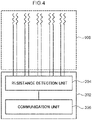
- the communication module 202 has a resistance detection unit 204 and a communication unit 206, and note that the communication module 202 also has a power supply unit (not illustrated).
- the resistance detection unit 204 detects the resistance value between the first electrode part 20A and the second electrode part 20B.
- the data of the detected resistance value is transmitted to an external device by the communication unit 206.
- the embodiment may be such that the motion detection member 150 according to the present embodiment transmits the data of the detected resistance value to the external device in a wired manner.
- At least respective portions (in the present embodiment, the wave-shaped parts 32A and 32B) of the first detection wiring part 30A and the second detection wiring part 30B are in contact with each other in a state before expansion of the expanding/contracting portion of the finger part 2 in the glove-shaped wearable part 10 (see Fig. 3A ).
- at least a portion of the conductive linear body 40A2 constituting the first detection wiring part 30A and at least a portion of the conductive linear body 40B2 constituting the second detection wiring part 30B are in contact with each other.
- the first detection wiring part 30A and the second detection wiring part 30B move apart from each other at the moment when a certain expansion rate is reached (see Fig. 3B ).
- the conductive linear body 40A2 constituting the first detection wiring part 30A and the conductive linear body 40B2 constituting the second detection wiring part 30B move apart from each other.
- the period of the wave-shaped part 32A of the first detection wiring part 30A and the wave-shaped part 32B of the second detection wiring part 30B becomes long, and the amplitude thereof becomes small.
- the first detection wiring part 30A and the second detection wiring part 30B move apart from each other.
- the resistance value between the first electrode part 20A and the second electrode part 20B changes. That is, the resistance value increases. Specifically, the state between the first electrode part 20A and the second electrode part 20B shifts from a conduction state to a non-conduction state.
- the motion of the finger (bending of the proximal interphalangeal joint of the finger) can then be detected by detecting the change in resistance value between the first electrode part 20A and the second electrode part 20B that accompanies the expansion.
- the bending of the finger of the hand (the bending of the proximal interphalangeal joint) is released and the expansion of the expanding/contracting portion of the finger part 2 is released (that is, when it contracts)
- at least a portion of the first detection wiring part 30A and at least a portion of the second detection wiring part 30B which have been apart from each other, come into contact with each other at the moment when a certain expansion rate is reached (see Fig. 3A ). That is, the resistance value is reduced.
- the state between the first electrode part 20A and the second electrode part 20B shifts from a non-conduction state to a conduction state.
- the motion of a finger (release of bending of the proximal interphalangeal joint of the finger) can be detected by detecting a change in the resistance value between the first electrode part 20A and the second electrode part 20B that accompanies the expansion and contraction.
- Fig. 9 illustrates an example of "the relationship between the resistance value between the first electrode part 20A and the second electrode part 20B, and the expansion rate" in the first expansion/contraction based on the measurement results of Fig. 8 .
- the expanding/contracting portion that is, the expanding/contracting portion of the wearable part, at which the detection wiring part is provided
- the resistance value between the first electrode part 20A and the second electrode part 20B changes with a certain expansion rate as a boundary. Specifically, the state between the first electrode part 20A and the second electrode part 20B shifts from a conduction state to a non-conduction state, and from a non-conduction state to a conduction state.
- the motion detection member 150 can detect the motion of a finger (bending of the proximal interphalangeal joint of the finger and release thereof) by detecting a change in the resistance value between the first electrode part 20A and the second electrode part 20B that accompanies the expansion and contraction of the expanding/contracting portion of the finger part 2 (that is, the expanding/contracting portion of the wearable part, at which the detection wiring part is provided).
- the motion detection member 150 can detect the motion of a finger, it can be used in an input device for displaying hand states (for example, rock, paper, scissors in a rock-paper-scissors game) or in an input device for operating games, or the like.
- hand states for example, rock, paper, scissors in a rock-paper-scissors game
- an input device for operating games or the like.
- the wiring electrode part is not limited to the configuration of the wiring electrode part 100 illustrated in Fig. 3 , and may be modified or improved.
- connection wiring part will be omitted.
- the wiring electrode part may be, for example, the wiring electrode part 101 illustrated in Fig. 10A .
- the first detection wiring part 30A and the second detection wiring part 30B are provided so as to be apart from each other in a state before expansion of the expanding/contracting portion (hereinafter, simply referred to as the "expanding/contracting portion of the wearable part") of the wearable part, at which the detection wiring part 30 is provided.
- the wave-shaped part 32A of the first detection wiring part 30A and the wave-shaped part 32B of the second detection wiring part 30B face each other substantially in parallel and are provided so as to be apart from each other.
- At least a portion of the first detection wiring part 30A and at least a portion of the second detection wiring part 30B which have been apart from each other, come into contact with each other at the moment when a certain expansion rate is reached (see Fig. 10B ).
- at least a portion of the conductive linear body 40A2 constituting the first detection wiring part 30A and at least a portion of the conductive linear body 40B2 constituting the second detection wiring part 30B come into contact with each other.
- the period of the wave-shaped part 32A of the first detection wiring part 30A and the wave-shaped part 32B of the second detection wiring part 30B becomes long, and the amplitude thereof becomes small, while contact is made therebetween.
- the resistance value between the first electrode part 20A and the second electrode part 20B changes. That is, the resistance value is reduced. Specifically, the state between the first electrode part 20A and the second electrode part 20B shifts from a non-conduction state to a conduction state.
- the motion of the wearing body can then be detected by detecting the change in resistance value between the first electrode part 20A and the second electrode part 20B that accompanies the expansion.
- the first detection wiring part 30A and the second detection wiring part 30B which have been in contact with each other, move apart from each other at the moment when a certain expansion rate is reached (see Fig. 10A ). That is, the resistance value increases. Specifically, the state between the first electrode part 20A and the second electrode part 20B shifts from a conduction state to a non-conduction state.
- the motion of the wearing body can be detected by detecting a change in resistance value between the first electrode part 20A and the second electrode part 20B that accompanies the contraction.
- the wiring electrode part may be, for example, the wiring electrode part 102 illustrated in Fig. 11A .
- the wiring electrode part 102 includes, as the wave-shaped part 32A of the first detection wiring part 30A, a first wave-shaped part 32A1 and a second wave-shaped part 32A2 which has a different contact length with the wave-shaped part 32B of the second detection wiring part 30B than first wave-shaped part 32A1.
- the wiring electrode part 102 has, as the wave-shaped part 32A of the first detection wiring part 30A, a first wave-shaped part 32A1 and a second wave-shaped part 32A2 which has a different period and/or amplitude than the first wave-shaped part 32A1.
- the present example represents an example in which the second wave-shaped part 32A2 has a shorter contact length with the wave-shaped part 32B of the second detection wiring part 30B than the first wave-shaped part 32A1.
- an example is illustrated in which the second wave-shaped part 32A2 has a shorter period and a smaller amplitude than the first wave-shaped part 32A1.
- the expanding/contracting portion (hereinafter, simply referred to as the "expanding/contracting portion of the wearable part") of the wearable part, at which the detection wiring part 30 is provided, expands as a result of the motion of the wearing body, a portion of the first detection wiring part 30A and a portion of the second detection wiring part 30B, which have been in contact with each other, move apart from each other at the moment when a certain expansion rate is reached (see Fig. 11B ). Specifically, the second wave-shaped part 32A2 of the first detection wiring part 30A and the wave-shaped part 32B of the second detection wiring part 30B move apart from each other.
- the second wave-shaped part 32A2 of the first detection wiring part 30A and the wave-shaped part 32B of the second detection wiring part 30B move apart from each other at the moment when a certain expansion rate is reached (see Fig. 11C ).
- the second wave-shaped part 32A2 of the first detection wiring part 30A and the wave-shaped part 32B of the second detection wiring part 30B move apart from each other first
- the first wave-shaped part 32A1 of the first detection wiring part 30A and the wave-shaped part 32B of the second detection wiring part 30B move apart from each other subsequently.
- the resistance value between the first electrode part 20A and the second electrode part 20B gradually changes. That is, the resistance value gradually increases in proportion to the increase in the contact resistance due to the partial separation between the first detection wiring part 30A and the second detection wiring part 30B. Specifically, in a conductive state between the first electrode part 20A and the second electrode part 20B, the resistance value increases by a certain value, and then the conductive state is changed to a non-conductive state.
- the gradual motion of the wearing body can then be detected by detecting the gradual change in resistance value between the first electrode part 20A and the second electrode part 20B that accompanies the expansion.
- the first wave-shaped part 32A1 of the first detection wiring part 30A and the wave-shaped part 32B of the second detection wiring part 30B which have been apart from each other, come into contact with each other at the moment when a certain expansion rate is reached (see Fig. 11B ).
- the second wave-shaped part 32A2 of the first detection wiring part 30A and the wave-shaped part 32B of the second detection wiring part 30B which have been apart from each other, come into contact with each other at the moment when a certain expansion rate is reached (see Fig. 11A ). That is, the resistance value is gradually reduced.
- the state between the first electrode part 20A and the second electrode part 20B shifts from a non-conduction state to a conduction state, whereupon the resistance value is reduced in the conductive state.
- the gradual motion of the wearing body can be detected by detecting a gradual change in the resistance value between the first electrode part 20A and the second electrode part 20B that accompanies the contraction.
- a second modification may have a plurality of regions having mutually different contact lengths in the contact section between the wave-shaped part 32A of the first detection wiring part 30A and the wave-shaped part 32B of the second detection wiring part 30B, according to an intended gradual change in the resistance value between the first electrode part 20A and the second electrode part 20B.
- the first detection wiring part 30A and/or second detection wiring part 30B may have a plurality of wave-shaped parts having different periods and/or amplitudes.
- the gradual change in the resistance value indicates that the resistance value changes in the course of expansion of the expanding/contracting portion of the wearable part, and the resistance value changes again once the resistance value change is complete.
- the wiring electrode part may be, for example, the wiring electrode part 103 illustrated in Fig. 12A .
- the wiring electrode part 103 further includes a third electrode part 20C as electrode part 20, and a third detection wiring part 30C as the detection wiring part 30.
- the third electrode part 20C includes a conductive linear body 40C1.
- the third detection wiring part 30C includes a conductive linear body 40C2 extending from the conductive linear body 40C1 of third electrode part 20C. That is, the third electrode part 20C and the third detection wiring part 30C are configured from at least the same one conductive linear body 40.
- the third detection wiring part 30C is electrically connected to the third electrode part 20C.
- the third detection wiring part 30C is provided separately from the first detection wiring part 30A and the second detection wiring part 30B so as to be interposed between the first detection wiring part 30A and the second detection wiring part 30B and so as to be in contact with at least a portion of the first detection wiring part 30A and at least a portion of the second detection wiring part 30B in a state before expansion of the expanding/contracting portion (hereinafter, simply referred to as the "expanding/contracting portion of the wearable part") of a wearable part, at which the detection wiring part 30 is provided.
- the third detection wiring part 30C has, for example, a wave-shaped part 32C in which the conductive linear body 40C2 is provided in a wave shape.
- the wave-shaped part 32C of the third detection wiring part 30C is in point contact or line contact with the wave-shaped part 32A of the first detection wiring part 30A and the wave-shaped part 32B of the second detection wiring part 30B.
- the contact length between the wave-shaped part 32C of the third detection wiring part 30C and the wave-shaped part 32A of the first detection wiring part 30A is different from the contact length between the wave-shaped part 32C of the third detection wiring part 30C and the wave-shaped part 32B of the second detection wiring part 30B.
- the periods and/or amplitudes of the wave-shaped part 32C of the third detection wiring part 30C, the wave-shaped part 32A of the first detection wiring part 30A, and the wave-shaped part 32B of the second detection wiring part 30B are different.
- the contact length between the wave-shaped part 32C of the third detection wiring part 30C and the wave-shaped part 32A of the first detection wiring part 30A is shorter than the contact length between the wave-shaped part 32C of the third detection wiring part 30C and the wave-shaped part 32B of the second detection wiring part 30B.
- the wave-shaped part 32C of the third detection wiring part 30C has a smaller amplitude than the wave-shaped part 32A of the first detection wiring part 30A and the wave-shaped part 32B of the second detection wiring part 30B.
- the first detection wiring part 30A and the third detection wiring part 30C which have been in contact with each other, move apart from each other at the moment when a certain expansion rate is reached (see Fig. 12B ).
- the wave-shaped part 32A of the first detection wiring part 30A and the wave-shaped part 32C of the third detection wiring part 30C move apart from each other.
- the second detection wiring part 30B and the third detection wiring part 30C which have been in contact with each other, move apart from each other at the moment when a certain expansion rate is reached (see Fig. 12C ).
- the wave-shaped part 32B of the second detection wiring part 30B and the wave-shaped part 32C of the third detection wiring part 30C move apart from each other.
- the first detection wiring part 30A and the third detection wiring part 30C move apart from each other first, and the second detection wiring part 30B and the third detection wiring part 30C move apart from each other subsequently.
- the resistance value between the first electrode part 20A and the third electrode part 20C changes. That is, the resistance value increases. Specifically, the state between the first electrode part 20A and the third electrode part 20C shifts from a conduction state to a non-conduction state.
- the resistance value between the second electrode part 20B and the third electrode part 20C changes. That is, the resistance value increases. Specifically, the state between the second electrode part 20B and the third electrode part 20C shifts from a conduction state to a non-conduction state.
- the motion of the wearing body can then be detected by detecting a change in the resistance value between the first electrode part 20A and the third electrode part 20C and a change in the resistance value between the second electrode part 20B and the third electrode part 20C that accompany the expansion.
- the second detection wiring part 30B and third detection wiring part 30C which have been apart from each other, come into contact with each other at the moment when a certain expansion rate is reached (see Fig. 12B ).
- the wave-shaped part 32B of the second detection wiring part 30B and the wave-shaped part 32C of the third detection wiring part 30C come into contact with each other.
- the first detection wiring part 30A and the third detection wiring part 30C which have been apart from each other, come into contact with each other at the moment when a certain expansion rate is reached (see Fig. 12A ). Specifically, the wave-shaped part 32A of the first detection wiring part 30A and the wave-shaped part 32C of the third detection wiring part 30C come into contact with each other.
- the second detection wiring part 30B and the third detection wiring part 30C come into contact with each other first, and the first detection wiring part 30A and the third detection wiring part 30C come into contact with each other subsequently.
- the gradual motion of the wearing body can be detected by detecting a change in the resistance value between the first electrode part 20A and the third electrode part 20C and a change in the resistance value between the second electrode part 20B and the third electrode part 20C that accompany the contraction.
- the second detection wiring part 30B and the third detection wiring part 30C may be separated first, and the first detection wiring part 30A and the third detection wiring part 30C may be separated subsequently.
- the wiring electrode part may be, for example, the wiring electrode part 104 illustrated in Fig. 13A .
- the first detection wiring part 30A and the second detection wiring part 30B are provided so as to be apart from each other in a state before expansion of the expanding/contracting portion (hereinafter, simply referred to as the "expanding/contracting portion of the wearable part") of the wearable part, at which the detection wiring part 30 is provided.
- the wave-shaped part 32A of the first detection wiring part 30A and the wave-shaped part 32B of the second detection wiring part 30B are provided so as to face each other at an angle (for example, the angle formed by the direction of extension of each wave-shaped part ranges from 3° to 30°) and so as to be apart from each other.
- At least a portion of the first detection wiring part 30A and at least a portion of the second detection wiring part 30B which have been apart from each other, come into contact with each other at the moment when a certain expansion rate is reached (see Fig. 13B ).
- at least a portion of the conductive linear body 40A2 constituting the first detection wiring part 30A and at least a portion of the conductive linear body 40B2 constituting the second detection wiring part 30B come into contact with each other.
- the tip side (the tip side not connected to the second electrode part 20B) of the wave-shaped part 32B of the second detection wiring part 30B comes into contact with the wave-shaped part 32A of the first detection wiring part 30A.
- the contact region increases between the first detection wiring part 30A and the second detection wiring part 30B (see Fig. 13C ). Specifically, the contact region increases between the conductive linear body 40A2 constituting the first detection wiring part 30A and the conductive linear body 40B2 constituting the second detection wiring part 30B.
- the contact region increases.
- the resistance value between the first electrode part 20A and the second electrode part 20B gradually changes. That is, when the first detection wiring part 30A and the second detection wiring part 30B first come into contact with each other, the state between the first electrode part 20A and the second electrode part 20B shifts from a non-conductive state to a conductive state. Next, when the contact region between the first detection wiring part 30A and the second detection wiring part 30B increases, the contact resistance decreases, and the resistance value between the first electrode part 20A and the second electrode part 20B is gradually reduced.
- the gradual motion of the wearing body can then be detected by detecting the gradual change in resistance value between the first electrode part 20A and the second electrode part 20B that accompanies the expansion.
- the contact region between the first detection wiring part 30A and the second detection wiring part 30B decreases ( Fig. 13B ).
- the first wave-shaped part 32A1 of the first detection wiring part 30A and the wave-shaped part 32B of the second detection wiring part 30B which have been in contact with each other, move apart from each other at the moment when a certain expansion rate is reached (see Fig. 13A ). That is, the resistance value gradually increases.
- the resistance value decreases in a conductive state between the first electrode part 20A and the second electrode part 20B, whereupon the first electrode part and the second electrode part come into a non-conductive state.
- the gradual motion of the wearing body can also be detected by detecting a gradual change in the resistance value between the first electrode part 20A and the second electrode part 20B that accompanies the contraction.
- the wiring electrode part may be, for example, the wiring electrode part 105 illustrated in Fig. 14A .
- the first detection wiring part 30A and the second detection wiring part 30B are integrally provided as the detection wiring part 30.
- the first detection wiring part 30A and the second detection wiring part 30B serving as the detection wiring part 30 are configured from one conductive linear body 40 extending from the conductive linear body 40 constituting the first electrode part 20A and the second electrode part 20B.
- the first electrode part 20A and the second electrode part 20B are electrically connected by one detection wiring part 30.
- the detection wiring part 30 may be configured from a plurality of conductive linear bodies 40.
- a contact section 34 is provided in which, in a state before expansion of the expanding/contracting portion (hereinafter, simply referred to as the "expanding/contracting portion of the wearable part") of the wearable part, at which the detection wiring part 30 is provided, the detection wiring part 30 is repeatedly bent or curved at 180° and at least portions of the detection wiring part 30 between the bent parts or the curved parts are in contact with each other.
- a contact section 34 is provided in which, in a state before expansion of the expanding/contracting portion of the wearable part, the conductive linear body 40 is repeatedly bent or curved at 180° and at least portions of the conductive linear body 40 between the bent parts or the curved parts are in contact with each other.
- the resistance value between the first electrode part 20A and the second electrode part 20B changes. That is, the resistance value increases as the conduction path increases.
- the motion of the wearing body can then be detected by detecting the change in resistance value between the first electrode part 20A and the second electrode part 20B that accompanies the expansion.
- the portions of the detection wiring part 30 are repeatedly bent or curved at 180° midway along the detection wiring part 30, and the contact section 34 is formed in which at least portions of the detection wiring part 30 between the bent parts or the curved parts are in contact with each other (see Fig. 14A ).
- the resistance value between the first electrode part 20A and the second electrode part 20B changes. That is, the resistance value is reduced as the conduction path decreases.
- the motion of the wearing body can also be detected by detecting a change in resistance value between the first electrode part 20A and the second electrode part 20B that accompanies the contraction.
- the amount of change in the resistance value between the first electrode part 20A and the second electrode part 20B can be controlled by increasing or decreasing the contact area between the portions of the detection wiring part 30 in the contact section of the detection wiring part 30.
- the electrode wiring part may be, for example, the wiring electrode part 106 illustrated in Fig. 15 . That is, an embodiment may be adopted in which the expanding/contracting portion of the glove-shaped wearable part, at which the detection wiring part is provided, is arranged at the surface of the corresponding position of the glove-shaped wearable part.
- the wiring electrode part 106 (the electrode part 20, detection wiring part 30, and connection wiring part 50) is provided at the expandable/contractible fabric material 60.
- the expandable/contractible fabric material 60 is configured from triple (three layers of) fabric material layers, namely, a front surface fabric material layer 60A constituting a front surface, a back surface fabric material layer 60B constituting a back surface, and an intermediate fabric material layer 60C provided between the front surface fabric material layer 60A and the back surface fabric material layer 60B. Note that the configuration of the expandable/contractible fabric material 60 is similar to the fabric material constituting the glove-shaped wearable part 10.
- the electrode part 20 is provided, for example, at the front surface fabric material layer 60A of the expandable/contractible fabric material 60.
- the detection wiring part 30 is provided, for example, at the intermediate fabric material layer 60C of the expandable/contractible fabric material 60.
- connection wiring part 50 is provided, for example, at the intermediate fabric material layer 60C of the expandable/contractible fabric material 60.
- the expandable/contractible fabric material 60 at which the electrode wiring part 106 is provided, is disposed at the surface of the corresponding position of the glove-shaped wearable part 10 by a well-known fixing means such as sewing or adhesion.
- the glove-shaped wearable part 10 can be configured from a well-known material such as resin, paper, leather, or the like instead of the fabric material.
- the electrode wiring part may be, for example, the wiring electrode part 107 illustrated in Fig. 16 . That is, an embodiment may be adopted in which the expanding/contracting portion of the glove-shaped wearable part, at which the detection wiring part is provided, is arranged at the surface of the corresponding position of the glove-shaped wearable part.
- a button electrode (a snap button or the like) serving as the electrode part 20 is arranged at the surface of the corresponding position of the glove-shaped wearable part 10 by using a well-known fixing means such as sewing or adhesion.
- the button electrode serving as the electrode part 20 may be connected to the communication module 202 via wiring, or may be directly connected to the communication module 202.
- the detection wiring part 30 is provided at the expandable/contractible fabric material 70.
- the expandable/contractible fabric material 70 is configured from triple (three layers of) fabric material layers, namely, a front surface fabric material layer 70A constituting the front surface, a back surface fabric material layer 70B constituting a back surface, and an intermediate fabric material layer 70C provided between the front surface fabric material layer 70A and the back surface fabric material layer 70B. Note that the configuration of the expandable/contractible fabric material 70 is similar to the fabric material constituting the glove-shaped wearable part 10.
- the expandable/contractible fabric material 70, at which the detection wiring part 30 is provided, is provided at the surface of the glove-shaped wearable part 10.
- connection wiring part 50 is provided so as to connect the electrode part 20 and the detection wiring part 30 at the surface of the glove-shaped wearable part 10.
- the connection wiring part 50 is covered with a well-known insulating sheet 72 such as a fabric material or a resin material.
- the glove-shaped wearable part 10 can be configured from a well-known material such as resin, paper, leather, or the like, instead of the fabric material.
- the expanding/contracting portion (hereinafter, simply referred to as the "expanding/contracting portion of the wearable part") of the wearable part, at which the detection wiring part 30 is provided may have an expansion rate range in which the resistance value between the first electrode part 20A and the second electrode part 20B changes by 2 times or more or by 1/2 or less (preferably 10 times or more or 1/10 or less, more preferably 100 times or more or 1/100 or less) within a range in which the change in the expansion rate is ⁇ 5% (see Figs. 8 to 9 ). That is, in the expanding/contracting portion of the wearable part, the resistance value between the first electrode part 20A and the second electrode part 20B may change by 2 times or more or by 1/2 or less while the expansion rate changes by 10% in the course of expansion.
- the expanding/contracting portion may have a region in which the maximum resistance value is 2 times or more or 1/2 or less (preferably 10 times or more or 1/10 or less, more preferably 100 times or more or 1/100 or less) the minimum resistance value within a range of Y-5% to Y+5%.
- This resistance value change is calculated using the ratio of resistance values at the moment when an intended expansion rate is reached and at the moment when the expansion rate changes by 10% after this moment.
- the range, for the ratio between the expansion rate and the maximum expansion rate (expansion rate/maximum expansion rate), in which the resistance value between the first electrode part 20A and the second electrode part 20B changes by 2 times or more or by 1/2 or less within a range in which the change in the expansion rate is ⁇ 5% may be in a range of 0. 1 to 0.9 (preferably 0.2 to 0.8).
- the ratio is in the aforementioned range, it is possible to efficiently detect the motion of the wearing body while preventing a malfunction.
- the change in the resistance value between the first electrode part 20A and the second electrode part 20B that accompanies the expansion/contraction of the expanding/contracting portion of the wearable part is measured as follows.
- the expanding/contracting portion of the wearable part While measuring the resistance value between the first electrode part 20A and the second electrode part 20B, the expanding/contracting portion of the wearable part is expanded to the maximum expansion at a speed of 1 mm/s, and then contracted at the same speed until returning to the original state. At such time, the resistance value is plotted every 1 second, and a change in the resistance value is measured. Note that the direction of expansion of the expanding/contracting portion of the wearable part is the direction in which a change in resistance value due to expansion/contraction should be detected.
- the expansion rate of the expanding/contracting portion of the wearable part is calculated using the formula: ((length in the direction of expansion at the time of expansion) - (length in the direction of expansion before expansion))/(length in the direction of expansion before expansion) ⁇ 100.
- the maximum expansion rate of the expanding/contracting portion of the wearable part is calculated using the formula: ((length in the direction of expansion at the maximum expansion) - (length in the direction of expansion before expansion))/(length in the direction of expansion before expansion) ⁇ 100.
- the maximum expansion of the expanding/contracting portion of the wearable part is the length at the time when the expanding/contracting portion of the wearable part no longer expands when the expanding/contracting portion is expanded using an appropriate tension. That is, the length in a case in which the expanding/contracting portion of the wearable part is expanded using the tension at which the expansion stops is taken as the maximum expansion of the expanding/contracting portion of the wearable part.
- the shape of the wearable part is not limited to a glove-shaped shape, rather, various shapes such as a cylindrical shape, a sheet shape, or a belt shape may be used, depending on the purpose.
- the shape of a supporter, a wristband, or the like can be adopted.
- the shape of a supporter, a wristband, or the like, in which fasteners are provided at both ends for being wound around the wearing body can be adopted.
- the embodiment may be such that the sheet-shaped wearable part is bonded to the wearing body using an adhesive.
- the shape of a suspender or the like can be adopted.
- the shape of the wearable part is selected according to the location for wearing on the wearing body.
- examples of locations for wearing on the wearing body include moving parts (neck, wrist, elbow, shoulder, knee, waist, ankle, foot, and the like) of a human body serving as the wearing body. However, they are not limited thereto.
- the motion detection member according to the present embodiment can be worn at various locations of the wearing body according to the shape of the wearable part.
- the motion of a moving part of the wearing body (such as motion in which a moving part such as an elbow or a knee moves at predetermined angle) and the number of motions thereof can be detected.
- the size of the arm and the waist can be measured.
- motion can also be detected using a plurality of measurements (for example, the motion of a person can be predicted and detected by measuring, in combination, the neck, the wrist, the elbow, the shoulder, the knee, the waist, the ankle, the foot, and the like).
- the motion detection member according to the present embodiment may also be provided with a well-known sensor other than the detection wiring part 30 (for example, a contact-type sensor or the like). By providing a well-known sensor other than the detection wiring part 30, superior motion detection is possible.
- a well-known sensor other than the detection wiring part 30 for example, a contact-type sensor or the like.
Abstract
Description
- The present disclosure relates to a motion detection member.
- Conventionally, for example, a motion detection member for detecting the motion of human body parts (such as an elbow, knee, waist, or finger) and the like, is known.
- For example, Japanese Patent Application Laid-Open (
JP-A) No. 2016-130940 - In addition,
JP-ANo. 2017-061770 - However, in the motion detection member disclosed in
JP-ANo. 2016-130940 - Meanwhile, in the motion detection member disclosed in
JP-ANo. 2017-061770 - Thus, there is a demand for a motion detection member having a novel structure that is highly durable and comfortable to wear.
- Therefore, an object of the present disclosure is to provide a motion detection member that is highly durable and comfortable to wear.
- The foregoing problem is solved by the following means.
- <1> A motion detection member for detecting motion of a wearing body, the motion detection member comprising:
- a wearable part that is to be worn on the wearing body, the wearable part including an expanding/contracting portion that is configured from an expandable/contractible fabric material that expands/contracts as a result of the motion of the wearing body; and
- a wiring electrode part including: a wiring part provided at at least a portion of the expanding/contracting portion of the wearable part, the wiring part including a first wiring part including a conductive linear body and a second wiring part including a conductive linear body; and an electrode part including a first electrode part electrically connected to the first wiring part and a second electrode part electrically connected to the second wiring part,
- wherein, when the expanding/contracting portion of the wearable part, at which the wiring part is provided, expands/contracts as a result of the motion of the wearing body, a contact state between the first wiring part and the second wiring part changes, so that a resistance value between the first electrode part and the second electrode part changes.
- <2> The motion detection member according to <1>, wherein:
- the first wiring part and the second wiring part are separately provided;
- in a case in which the first wiring part and the second wiring part are provided so that at least a portion of the first wiring part and at least a portion of the second wiring part are in contact with each other before expansion of the expanding/contracting portion of the wearable part, at which the wiring part is provided, when the expanding/contracting portion of the wearable part, at which the wiring part is provided, expands as a result of the motion of the wearing body, the first wiring part and the second wiring part move apart from each other; and
- in a case in which the first wiring part and the second wiring part are provided so as to be apart from each other before expansion of the expanding/contracting portion of the wearable part, at which the wiring part is provided, when the expanding/contracting portion of the wearable part, at which the wiring part is provided, expands as a result of the motion of the wearing body, at least a portion of the first wiring part and at least a portion of the second wiring part come into contact with each other.
- <3> The motion detection member according to <1> or <2>, wherein:
- the first wiring part and the second wiring part are separately provided;
- in a case in which the first wiring part and the second wiring part are provided so that at least a portion of the first wiring part and at least a portion of the second wiring part are in contact with each other before expansion of the expanding/contracting portion of the wearable part, at which the wiring part is provided, when the expanding/contracting portion of the wearable part, at which the wiring part is provided, expands as a result of the motion of the wearing body, a contact region between the first wiring part and the second wiring part gradually decreases; and
- in a case in which the first wiring part and the second wiring part are provided so as to be apart from each other before expansion of the expanding/contracting portion of the wearable part, at which the wiring part is provided, when the expanding/contracting portion of the wearable part, at which the wiring part is provided, expands as a result of the motion of the wearing body, the contact region between the first wiring part and the second wiring part gradually increases.
- <4> The motion detection member according to <1>, wherein:
- the first wiring part and the second wiring part are integrally provided; and
- when the expanding/contracting portion of the wearable part, at which the wiring part is provided, expands as a result of the motion of the wearing body, a conduction path of the first wiring part and the second wiring part lengthens.
- <5> The motion detection member according to any one of <1> to <4>, having an expansion rate range such that, when the expanding/contracting portion of the wearable part, at which the wiring part is provided, is expanded to a maximum expansion rate, the resistance value between the first electrode part and the second electrode part changes by two times or more or by 1/2 or less within a range of an expansion rate change of ±5%.
- <6> The motion detection member according to any one of <1> to <5>, wherein the resistance value between the first electrode part and the second electrode part gradually changes according to an expansion rate of the expanding/contracting portion of the wearable part, at which the wiring part is provided.
- <7> The motion detection member according to any one of <1> to <6>, wherein, when the expanding/contracting portion of the wearable part, at which the wiring part is provided, expands, a state between the first electrode part and the second electrode part shifts from a conduction state to a non-conduction state or from a non-conduction state to a conduction state.
- <8> The motion detection member according to any one of <1> to <7>, wherein a portion of the conductive linear body in at least one of the first electrode part or the second electrode part is bound by a yarn of the expandable/contractible fabric material of the expanding/contracting portion of the wearable part.
- <9> The motion detection member according to <8>, wherein the conductive linear body in at least one of the first electrode part or the second electrode part is woven into, knitted into, or embroidered onto the expandable/contractible fabric material of the expanding/contracting portion of the wearable part.
- <10> The motion detection member according to any one of <1> to <9>, wherein a portion of the conductive linear body in at least one of the first wiring part or the second wiring part is bound by a yarn of the expandable/contractible fabric material of the expanding/contracting portion of the wearable part.
- <11> The motion detection member according to <10>, wherein the conductive linear body in at least one of the first wiring part or the second wiring part is woven into, knitted into, or embroidered onto the expandable/contractible fabric material of the expanding/contracting portion of the wearable part.
- <12> The motion detection member according to any one of <1> to <11>, wherein at least one of the first wiring part or the second wiring part is provided inside the expandable/contractible fabric material of the expanding/contracting portion of the wearable part.
- <13> The motion detection member according to any one of <1> to <12>, wherein the conductive linear body included in at least one of the first electrode part, the second electrode part, the first wiring part, or the second wiring part is a conductive linear body that includes a carbon nanotube yarn.
- <14> The motion detection member according to any one of <1> to <13>, wherein the wearable part is a glove-shaped wearable part that is to be worn on a hand of a human body serving as the wearing body.
- <15> The motion detection member according to <14>, wherein the expanding/contracting portion, at which the wiring part is provided, faces at least one of a proximal interphalangeal joint or a metacarpophalangeal joint of a finger of the hand.
- <16> The motion detection member according to any one of <1> to <13>, wherein the wearable part is a cylindrical, sheet-shaped, or belt-shaped wearable part.
- <17> The motion detection member according to <16>, wherein the cylindrical, sheet-shaped, or belt-shape wearable part is a wearable part that is to be worn on a moving part of a human body serving as the wearing body.
- <18> The motion detection member according to any one of <1> to <17>, wherein the expanding/contracting portion of the wearable part, at which the wiring part is provided, is provided at a surface of the wearable part.
- According to the present disclosure, it is possible to provide a motion detection member that is highly durable and comfortable to wear.
-
-
Fig. 1 is a schematic plan view illustrating a motion detection member according to the present embodiment. -
Fig. 2 is a schematic cross-sectional view illustrating a motion detection member according to the present embodiment. -
Fig. 3A is a schematic plan view illustrating an expanding/contracting portion (an example of an expanding/contracting portion of a wearable part, at which a wiring part is provided) of a motion detection member according to the present embodiment. -
Fig. 3B is a schematic plan view illustrating an expanded state of an expanding/contracting portion (an example of the expanding/contracting portion of the wearable part, at which the wiring part is provided) of a finger part of the motion detection member according to the present embodiment. -
Fig. 4 is a block diagram illustrating the motion detection member according to the present embodiment. -
Fig. 5 is a schematic plan view illustrating an example in which a conductive linear body is woven into the motion detection member according to the present embodiment. -
Fig. 6 is a schematic plan view illustrating an example in which a conductive linear body is knitted into the motion detection member according to the present embodiment. -
Fig. 7 is a schematic plan view illustrating an example in which a conductive linear body is embroidered onto the motion detection member according to the present embodiment. -
Fig. 8 is a diagram illustrating an example of a "relationship between a resistance value between a first electrode part and a second electrode part, and a measurement time, and a relationship between an expansion rate and the measurement time" in a case in which expansion and contraction of an expanding/contracting portion (an example of the expanding/contracting portion of the wearable part, at which the wiring part is provided) up to a maximum expansion rate are repeated five times. -
Fig. 9 is a diagram illustrating an example of "a relationship between a resistance value and an expansion rate between a first electrode part and a second electrode part" in a first expansion/contraction based on the results ofFig. 9 . -
Fig. 10A is a schematic plan view illustrating a wiring electrode part of a first modification. -
Fig. 10B is a schematic plan view illustrating an expanded state of the wiring electrode part of the first modification. -
Fig. 11A is a schematic plan view illustrating a wiring electrode part of a second modification. -
Fig. 11B is a schematic plan view illustrating a first expanded state of the wiring electrode part of the second modification. -
Fig. 11C is a schematic plan view illustrating a second expanded state of the wiring electrode part of the second modification. -
Fig. 12A is a schematic plan view illustrating a wiring electrode part of a third modification. -
Fig. 12B is a schematic plan view illustrating a first expanded state of the wiring electrode part of the third modification. -
Fig. 12C is a schematic plan view illustrating a second expanded state of the wiring electrode part of the third modification. -
Fig. 13A is a schematic plan view illustrating a wiring electrode part of a fourth modification. -
Fig. 13B is a schematic plan view illustrating a first expanded state of the wiring electrode part of the fourth modification. -
Fig. 13C is a schematic diagram illustrating a second expanded state of the wiring electrode part of the fourth modification. -
Fig. 14A is a schematic plan view illustrating a wiring electrode part of a fifth modification. -
Fig. 14B is a schematic plan view illustrating an expanded state of the wiring electrode part of the fifth modification. -
Fig. 15 is a schematic cross-sectional view illustrating a wiring electrode part of a sixth modification. -
Fig. 16 is a schematic cross-sectional view illustrating a wiring electrode part of a seventh modification. - Hereinafter, an exemplary embodiment of the present disclosure will be described in detail.
- Note that, in the present specification, members having substantially the same functions are assigned the same reference signs throughout the drawings, and redundant descriptions may be omitted.
- A numerical range using "to" signifies a numerical range in which the numerical values indicated before and after "to" are included as a minimum value and a maximum value, respectively.
- In a numerical range described in stages, an upper limit value or a lower limit value described in one numerical range may be replaced with an upper limit value or a lower limit value of another numerical range described in stages.
- The motion detection member according to the present embodiment is a member for detecting the motion of a wearing body.
- The motion detection member according to the present embodiment includes:
- a wearable part that is to be worn on the wearing body, the wearable part including an expanding/contracting portion that is configured from an expandable/contractible fabric material that expands/contracts as a result of the motion of the wearing body; and
- a wiring electrode part including: a wiring part provided at at least a portion of the expanding/contracting portion of the wearable part, the wiring part including a first wiring part including a conductive linear body and a second wiring part including a conductive linear body; and an electrode part including a first electrode part electrically connected to the first wiring part and a second electrode part electrically connected to the second wiring part,
- wherein, when the expanding/contracting portion of the wearable part, at which the wiring part is provided, expands/contracts as a result of the motion of the wearing body, a contact state between the first wiring part and the second wiring part changes, so that a resistance value between the first electrode part and the second electrode part changes.
- In the motion detection member according to the present embodiment, when the expanding/contracting portion expands/contracts (that is, expands and contracts) as a result of motion of the wearing body, a contact state between the first wiring part and the second wiring part changes, so that a resistance value between the first electrode part and the second electrode part changes. By detecting the change in the resistance value, it is possible to detect the motion of the wearing body.
- Further, in the motion detection member according to the present embodiment, the wiring electrode part for detecting motion is configured from a conductive linear body. Therefore, durability is also high.
- In addition, a wiring part configured from a conductive linear body is provided at an expanding/contracting portion of the wearable part configured from an expandable/contractible fabric material. Therefore, discomfort is not readily felt when the motion detection member is worn on the wearing body, and the wearing feeling is excellent.
- Further, the glove-type input device, the glove equipped with a strain sensor, and the like, of
JP-ANo. 2016-130940 - Here, in the present specification, "the resistance value between the first electrode part and the second electrode part changes" indicates that 1) the resistance value increases or decreases while the state between the first electrode part and the second electrode part is a conductive state, or that 2) the state between the first electrode part and the second electrode part changes from a conductive state to a non-conductive state or from a non-conductive state to a conductive state. Note that the change in the resistance value does not include a change in the resistance value due to damage of the electrode part, the wiring part, or the junction between the electrode part and the wiring part.
- The phrase "at least a portion of the first wiring part and at least a portion of the second wiring part are in contact with each other" may also include an embodiment in which, in a case in which another wiring part other than the first wiring part or the second wiring part (for example, a third wiring part) is included, at least a portion of the first wiring part and at least a portion of the second wiring part are in contact with each other via the other wiring part.
- "The wiring part is provided at the expanding/contracting portion" indicates that "the wiring part is provided at the surface of an expandable/contractible fabric material" or "the wiring part is provided inside the expandable/contractible fabric material".
- Further, "the wiring part is provided at the surface of the expandable/contractible fabric material" indicates that the wiring part (that is, the conductive linear body) is provided at a fabric material layer that constitutes the front or back surface of the expandable/contractible fabric material (which may also be a fabric material layer partially constituting the front or back surface). In other words, "the wiring part is provided at the surface of the expandable/contractible fabric material" indicates that the electrode part or the wiring part (that is, the conductive linear body) is provided in a state where at least a portion of the conductive linear body constituting the wiring part is exposed from the expandable/contractible fabric material.
- Meanwhile, "the wiring part is provided inside the expandable/contractible fabric material" indicates that the wiring part (that is, the conductive linear body) is provided at the inner layer of the expandable/contractible fabric material, for example, in the fabric material layer serving as the inner layer of the expandable/contractible fabric material or between the fabric material layers.
- "The wearable part includes an expanding/contracting portion configured from an expandable/contractible fabric material" encompasses both an embodiment in which a position corresponding to the expanding/contracting portion of the wearable part is configured from an expandable/contractible fabric material, and a wiring part is provided at the expandable/contractible fabric material, and an embodiment in which an expandable/contractible fabric material having a wiring part is separately bonded to the surface at a position corresponding to the expanding/contracting portion of the wearable part. Note that examples of the method of providing the expanding/contracting portion include bonding using an adhesive, attachment by sewing, and the like.
- That is, the motion detection member includes, for example, both an embodiment in which a wiring part is provided at a position corresponding to the expanding/contracting portion of the wearable part that is configured from a fabric material or the like (such as a glove or a wristband), and an embodiment in which an expandable/contractible fabric material having a wiring part is separately bonded to the surface at a position corresponding to the expanding/contracting portion of a conventional wearable part (such as a glove or a wristband) configured from a known material such as a fabric material, a resin, paper, or leather.
- Hereinafter, an example of the motion detection member according to the present embodiment will be described with reference to the drawings.
- A
motion detection member 150 according to the present embodiment is a glove-shaped member as illustrated inFig. 1 . - Specifically, the
motion detection member 150 includes, for example, a glove-shaped wearable part 10 (an example of a wearable part), awiring electrode part 100, and acommunication module 202. - The glove-shaped
wearable part 10 is a glove-shaped wearable part that is to be worn on a hand of a human body serving as a wearing body. - The glove-shaped
wearable part 10 includes awrist part 1 to be worn on a wrist of a human body, afinger part 2 to be worn on a finger of the human body, and abody part 3 connecting thewrist part 1 and thefinger part 2. - Note that the
wrist part 1, a connecting part connecting thefinger part 2 and the body part 3 (a portion corresponding to the metacarpophalangeal joint), and the finger part 2 (a portion corresponding to the distal interphalangeal joint and the proximal interphalangeal joint) corresponds to an example of the "expanding/contracting portion that expands/contracts as a result of motion of the wearing body". - Here, a portion of the
finger part 2 facing the dorsal side of the proximal interphalangeal joint corresponds to an example of the "expanding/contracting portion of the wearable part, at which the wiring part is provided". - Here, the glove-shaped
wearable part 10 includes, for example, fivefinger parts 2 corresponding to respective fingers. Specifically, the glove-shapedwearable part 10 has, as thefinger parts 2, for example, a thumb part 2Athat is to be worn on the thumb, anindex finger part 2B that is to be worn on the index finger, amiddle finger part 2C that is to be worn on the middle finger, aring finger part 2D that is to be worn on the ring finger, and alittle finger part 2E that is to be worn on the little finger. - However, the configuration of the
finger part 2 is not limited to the configuration. The glove-shapedwearable part 10 may include, as thefinger part 2, for example, two portions, namely, a thumb part that is to be worn on the thumb, and a finger part that is to be worn on the index finger, the middle finger, the ring finger, and the little finger. - The glove-shaped
wearable part 10 is configured, for example, from triple (three layers of) fabric material layers, namely, a front surfacefabric material layer 10A constituting a front surface, a back surfacefabric material layer 10B constituting a back surface, and an intermediatefabric material layer 10C provided between the front surfacefabric material layer 10A and the back surfacefabric material layer 10B. - The glove-shaped
wearable part 10 may be configured, for example, from one (single) fabric material layer, or from double (two) or quadruple (four) fabric material layers or more instead of the triple fabric material layers. - Note that multi-layer wearable part configured from two or more fabric material layers may be manufactured by, for example, a method of manufacturing respective fabric material layers and then sewing them together, or the multi-layer glove-shaped
wearable part 10 may be collectively manufactured by a weaving or knitting machine. - The glove-shaped
wearable part 10 is configured from an expandable/contractible fabric material, for example. In this regard, it is possible to configure the glove-shapedwearable part 10 from a soft fabric material, and to configure at least a portion of thefinger part 2 facing the dorsal side of the proximal interphalangeal joint (an example of the expanding/contracting portion of the wearable part, at which the wiring part is provided) from an expandable/contractible fabric material. - Typical examples of the expandable/contractible fabric material are woven or knitted fabrics. The glove-shaped
wearable part 10 may also be a nonwoven fabric. - Examples of woven or knitted fabrics include woven fabrics such as plain weave, twill weave, satin weave, and well-known weave applications; and knitted fabrics such as weft knitting, warp knitting, lace knitting, and well-known knitting applications.
- The yarn (linear body) constituting the expandable/contractible fabric material is an insulating yarn. The insulating yarn refers to a yarn having a line resistance of 1.0 × 10⁶ Q/cm or more. The line resistance of the insulating yarn is a line resistance measured using the same method as for the line resistance of the conductive linear body described subsequently.
- As the expandable/contractible fabric material, a woven or knitted fabric using an elastic yarn is preferably applied.
- Examples of the elastic yarn include a covered yarn (single covered yarn or double covered yarn) for which an inelastic yarn is wound in a coil shape around an outer periphery of an elastic yarn, a core spun yarn for which an elastic yarn and an inelastic yarn are spun and twisted, an air-interlaced covered yarn for which an inelastic yarn is wound around an outer periphery of an elastic yarn using a pneumatic nozzle, and a twisted yarn for which an elastic yarn and an inelastic yarn are twisted.
- Examples of the elastic yarn include yarns of fibers exhibiting so-called rubber-like elasticity, such as polyurethane elastic fibers, polyester elastic fibers, and polyamide elastic fibers.
- Examples of the inelastic yarn include yarns of synthetic fibers (polyester fiber, polyamide fiber, acrylic fiber, polypropylene fiber, and rayon fiber) and natural fibers (fibers such as cotton, silk, hemp, and wool).
- A
wiring electrode part 100 includes anelectrode part 20, awiring part 30, and awiring part 50. - The
electrode part 20 includes afirst electrode part 20A and asecond electrode part 20B, and is electrically connected to thecommunication module 202. - The wiring part 30 (hereinafter, referred to as the "
detection wiring part 30") has afirst wiring part 30A and asecond wiring part 30B, and in thewiring part 30, a contact state between thefirst wiring part 30A and thesecond wiring part 30B changes when a portion of thefinger part 2 facing a dorsal side of a proximal interphalangeal joint of a finger expands/contracts (hereinafter also referred to as "when the expanding/contracting portion of thefinger part 2 expands/contracts") as a result of bending of the proximal interphalangeal joint of the finger (an example of motion of a wearing body). - The
wiring part 50 has afirst wiring part 50A and asecond wiring part 50B, and is a connection wiring part (hereinafter referred to as the "connection wiring part 50") for electrically connecting theelectrode part 20 and thewiring part 30. - Note that the
connection wiring part 50 is a wiring part that is provided if necessary, and theelectrode part 20 and thedetection wiring part 30 may be directly connected. - In the
electrode part 20, thefirst electrode part 20A and thesecond electrode part 20B are each provided, for example, at the dorsal side of thewrist part 1 of the glove-shapedwearable part 10. However, the arrangement position of the electrodes is not particularly limited, and may be, for example, the palm side of thewrist part 1 of the glove-shapedwearable part 10 or the palm side of thebody part 3 of the glove-shapedwearable part 10. - Note that three or
more electrode parts 20 may be provided depending on the purpose. Only oneelectrode part 20 may also be provided. - For example, one electrode part may be a common electrode, and two or
more wiring parts 50 may be connected to one electrode part. Examples of the present embodiment include an embodiment in which one of the twowiring parts 50 connected to thedetection wiring part 30 disposed on thering finger part 2D and one of the twowiring parts 50 connected to thedetection wiring part 30 disposed on thelittle finger part 2E are connected to one electrode part serving as a common electrode. - For example, as illustrated in
Fig. 2 , theelectrode part 20 is provided at the front surfacefabric material layer 10A of the glove-shapedwearable part 10. That is, theelectrode part 20 is provided at the surface of the glove-shapedwearable part 10. - Note that the
electrode part 20 may be provided at the intermediatefabric material layer 10C of the glove-shapedwearable part 10. That is, theelectrode part 20 may be provided inside the glove-shapedwearable part 10. This is because, even when theelectrode part 20 is provided inside the glove-shapedwearable part 10, a connection can be established using a pin-shaped electrode or the like. - The
detection wiring part 30 is provided at a portion of the finger part 2 (all parts: thethumb part 2A,index finger part 2B,middle finger part 2C,ring finger part 2D, andlittle finger part 2E) facing the dorsal side of the proximal interphalangeal joint of the finger. - However, the arrangement position of the
detection wiring part 30 is not limited to that of the foregoing embodiment, and may be as per the following embodiments, depending on the purpose:
An embodiment in which thedetection wiring part 30 is provided at a portion of thefinger part 2 facing the dorsal side of the proximal interphalangeal joint and/or the dorsal side of the metacarpophalangeal joint of the finger. - An embodiment in which the
detection wiring part 30 is provided at a portion of thefinger part 2 facing the palm side of the proximal interphalangeal joint and/or the palm side of the metacarpophalangeal joint of the finger. - An embodiment in which a portion of the plurality of
detection wiring parts 30 is provided at a position facing the portion of thefinger part 2 facing the dorsal side of the finger, and the other portion is provided at a position facing the portion of thefinger part 2 facing the palm side of the finger (for example, an embodiment in which adetection wiring part 30 is provided at a position facing the portion of thethumb part 2A facing the palm side of the thumb, and adetection wiring part 30 is provided at a position facing the portion of theindex finger part 2B, themiddle finger part 2C, thering finger part 2D, and thelittle finger part 2E that face the dorsal side of the index finger part, the middle finger part, the ring finger part, and the little finger part). - An embodiment in which a
detection wiring part 30 is provided at at least one of thethumb part 2A, theindex finger part 2B, themiddle finger part 2C, thering finger part 2D, or thelittle finger part 2E. - In the
detection wiring part 30, the firstdetection wiring part 30A is electrically connected to thefirst electrode part 20A. Further, the seconddetection wiring part 30B is electrically connected to thesecond electrode part 20B. - The first
detection wiring part 30A and the seconddetection wiring part 30B are separately provided so as to be at least partially in contact with each other in a state before expansion of the expanding/contracting portion of thefinger part 2. - However, in a case in which a portion of the
detection wiring parts 30 is provided at a position facing the portion of thethumb part 2A facing the palm side of the finger (for example, in a case in which adetection wiring part 30 is provided at a position facing the portion of thethumb part 2A facing the palm side of the thumb, and adetection wiring part 30 is provided at a position facing the portion of theindex finger part 2B, themiddle finger part 2C, thering finger part 2D, and thelittle finger part 2E facing the dorsal side of the index finger part, the middle finger part, the ring finger part, and the little finger part), in thedetection wiring part 30 at a position facing the portion of thethumb part 2A facing the palm side of the thumb, the firstdetection wiring part 30A and the seconddetection wiring part 30B are separately provided so as to be apart from each other in a state before expansion of the expanding/contracting portion of thefinger part 2. - Note that an embodiment in which the first
detection wiring part 30A and the seconddetection wiring part 30B are separately provided so as to be apart from each other in a state before expansion of the expanding/contracting portion of thefinger part 2, will be described in a first modification. - The first
detection wiring part 30A extends, for example, along the longitudinal direction of thefinger part 2. The first detection wiring part 30Ahas a wave-shapedpart 32A that is obtained by providing a conductive linear body 40A2 in a wave shape. - The second
detection wiring part 30B extends, for example, along the longitudinal direction of thefinger part 2. The seconddetection wiring part 30B also has a wave-shapedpart 32B that is obtained by providing a conductive linear body 40B2 in a wave shape. - In a state before expansion of the expanding/contracting portion of the
finger part 2, the wave-shapedpart 32A of the firstdetection wiring part 30A and the wave-shapedpart 32B of the seconddetection wiring part 30B are in point contact or line contact with each other. - Note that both the first
detection wiring part 30A and the seconddetection wiring part 30B may not have a wave-shaped part that is obtained by providing the conductive linear body 40A2 or the conductive linear body 40B2 in a wave shape, and may be configured to have only a linear part provided in a straight line. Further, the firstdetection wiring part 30A and the seconddetection wiring part 30B may both have a bent part that is obtained by bending the conductive linear body 40A2 or the conductive linear body 40B2. - The
detection wiring part 30 is provided inside the glove-shapedwearable part 10. Specifically, for example, as illustrated inFig. 2 , thedetection wiring part 30 is provided at the intermediatefabric material layer 10C, which is a fabric material layer (which may also be a fabric material layer partially serving as an inner layer) of the inner layer of the glove-shapedwearable part 10 that is configured from three fabric material layers, whereby thedetection wiring part 30 can be provided inside the glove-shapedwearable part 10. Here, for example, thedetection wiring part 30 may be provided between the fabric material layers of the glove-shapedwearable part 10, which is configured from two fabric material layers. - Note that the
detection wiring part 30 may be provided at the surface of the glove-shapedwearable part 10. For example, thedetection wiring part 30 may be provided at the front surfacefabric material layer 10A or the back surfacefabric material layer 10B of a glove-shapedwearable part 10 that is configured from three fabric material layers. However, thedetection wiring part 30 is preferably provided inside the glove-shapedwearable part 10 from the viewpoint of insulation from the outside by the glove-shapedwearable part 10. - In the
connection wiring part 50, the firstconnection wiring part 50A electrically connects thefirst electrode part 20A and thefirst wiring part 30A. The secondconnection wiring part 50B electrically connects thesecond electrode part 20B and thesecond wiring part 30B. - The
connection wiring part 50 is provided at thebody part 3 of the glove-shapedwearable part 10 facing the dorsal side of the hand. - However, the arrangement position of the
connection wiring part 50 is not limited to the embodiment, and is set according to the arrangement positions of theelectrode part 20 and thedetection wiring part 30. - The
connection wiring part 50 is provided inside the glove-shapedwearable part 10. Specifically, for example, as illustrated inFig. 2 , theconnection wiring part 50 is provided at the intermediatefabric material layer 10C, which is a fabric material layer (which may also be a fabric material layer partially serving as an inner layer) of the inner layer of the glove-shapedwearable part 10 that is configured from three fabric material layers, whereby theconnection wiring part 50 can be provided inside the glove-shapedwearable part 10. Here, for example, theconnection wiring part 50 may be provided between the fabric material layers of the glove-shapedwearable part 10, which is configured from two fabric material layers. - Note that the
connection wiring part 50 may be provided at the surface of the glove-shapedwearable part 10. For example, theconnection wiring part 50 may be provided at the front surfacefabric material layer 10A or the back surfacefabric material layer 10B of the glove-shapedwearable part 10, which is configured from three fabric material layers. However, theconnection wiring part 50 is preferably provided inside the glove-shapedwearable part 10 from the viewpoint of insulation from the outside by the glove-shapedwearable part 10. - Each of the
electrode part 20, thedetection wiring part 30, and theconnection wiring part 50 includes a conductivelinear body 40. That is, the region where the conductivelinear body 40 is disposed is used for theelectrode part 20, thedetection wiring part 30, and theconnection wiring part 50. - Specifically, for example, the
first electrode part 20A includes a conductive linear body 40A1. - The first
connection wiring part 50A includes a conductive linear body 40A3 extending from the conductive linear body 40A1 of thefirst electrode part 20A. - The first
detection wiring part 30A includes a conductive linear body 40A2 extending from the conductive linear body 40A3 of the firstconnection wiring part 50A. - That is, the
first electrode part 20A and the firstdetection wiring part 30A are configured from at least the same one conductivelinear body 40. - Here, for example, the
second electrode part 20B includes a conductive linear body 40B1. - The second
connection wiring part 50B includes a conductive linear body 40B3 extending from the conductive linear body 40B1 of thesecond electrode part 20B. - The second
detection wiring part 30B includes a conductive linear body 40B2 extending from the conductive linear body 40B3 of the secondconnection wiring part 50B. - That is, the
second electrode part 20B and the seconddetection wiring part 30B are configured from at least the same one conductivelinear body 40. - The
first electrode part 20A and the firstdetection wiring part 30A, and thesecond electrode part 20B and the seconddetection wiring part 30B, respectively, are configured from the same one conductivelinear body 40, whereby a connection failure between theelectrode part 20 and thedetection wiring part 30 is suppressed. - Note that the same one conductive
linear body 40 may also include a linear body in which end portions of conductivelinear bodies 40 are connected to each other by knotting, twisting, or the like without using a connecting material (solder, conductive paste, or the like) or a connecting member (crimping, a connector, or the like) other than a linear body. - However, each of the
electrode part 20, thedetection wiring part 30, and theconnection wiring part 50 may also include a plurality of conductivelinear bodies 40. Here, thefirst electrode part 20A, the firstdetection wiring part 30A, and the firstconnection wiring part 50A, and thesecond electrode part 20B, the seconddetection wiring part 30B, and the secondconnection wiring part 50B, respectively, may not be configured from the same one conductivelinear body 40. - For example, the ends of conductive
linear bodies 40 of thefirst electrode part 20A, the firstdetection wiring part 30A, and the firstconnection wiring part 50A, and the ends of thesecond electrode part 20B, the seconddetection wiring part 30B, and the secondconnection wiring part 50B, respectively, may be connected to each other using a connecting material (solder, conductive paste, or the like) or a connecting member (crimping, a connector, or the like) other than a linear body. - In at least one of the
electrode part 20, thedetection wiring part 30, and theconnection wiring part 50, for example, at least a portion of the conductivelinear body 40 is bound by the yarn of the glove-shapedwearable part 10. - Such an embodiment is preferable from the viewpoint that the conductive
linear body 40 functioning as a conductive material can also be used as a means for fixing to the glove-shapedwearable part 10 as theelectrode part 20, thedetection wiring part 30, and theconnection wiring part 50. - The conductive
linear body 40 bound to the glove-shapedwearable part 10 may be the same one conductivelinear body 40 included in theelectrode part 20, thedetection wiring part 30, and theconnection wiring part 50, or may be another conductivelinear body 40 included in only one of theelectrode part 20, thedetection wiring part 30, and theconnection wiring part 50. - In at least one of the
electrode part 20, thedetection wiring part 30, and theconnection wiring part 50, the conductivelinear body 40 may not be bound by the yarn of the glove-shapedwearable part 10. - For example, in a case in which at least one of the
electrode part 20, thedetection wiring part 30, and theconnection wiring part 50 is fixed to the glove-shapedwearable part 10 using an adhesive, when at least one of theelectrode part 20, thedetection wiring part 30, and theconnection wiring part 50 is sewn to the glove-shapedwearable part 10 by using an insulating yarn, at least one of theelectrode part 20, thedetection wiring part 30, and theconnection wiring part 50 can be fixed to the glove-shapedwearable part 10 even when the conductivelinear body 40 is not bound by the yarn of the glove-shapedwearable part 10. - For example, a rectangular region in which the conductive
linear body 40 is repeatedly bent or curved at 180° is formed. This rectangular region is formed by binding a portion of the conductivelinear body 40 to the yarn of the front surfacefabric material layer 10A of the glove-shapedwearable part 10. Further, this rectangular region may be used as aplanar electrode part 20. - Note that a region in which a conductive
linear body 40 is arranged in a spiral shape may also be used as theelectrode part 20. Here, an arbitrary planar shape (polygon, circle, or the like) in which the conductivelinear body 40 is bent or curved may also be used as theelectrode part 20. - Meanwhile, a region is formed in which the conductive
linear body 40 is extended from theelectrode part 20 in a linear shape, a wave shape, a bent shape, or a combination thereof. This region is formed by binding a portion of the conductivelinear body 40 to the yarn of the intermediatefabric material layer 10C of the glove-shapedwearable part 10. This region may be used as thedetection wiring part 30 and theconnection wiring part 50. - Specifically, in a case in which the glove-shaped
wearable part 10 is a woven fabric, as illustrated inFig. 5 , theelectrode part 20, thedetection wiring part 30, and theconnection wiring part 50 are preferably configured by weaving the conductivelinear body 40 into a woven structure of a woven fabric that is woven with warps and wefts, from the viewpoint that the glove-shapedwearable part 10, theelectrode part 20, thedetection wiring part 30, and theconnection wiring part 50 can be simultaneously formed when the glove-shapedwearable part 10 is formed by weaving, and from the viewpoint of improving the integrity of the glove-shapedwearable part 10, theelectrode part 20, thedetection wiring part 30, and theconnection wiring part 50. - In a case in which the glove-shaped
wearable part 10 is a knitted fabric, as illustrated inFig. 6 , it is preferable that theelectrode part 20, thedetection wiring part 30, and theconnection wiring part 50 are configured by knitting the conductivelinear body 40 in the aforementioned shape into a knitted structure of the knitted fabric in which a loop-shaped yarn is knitted, from the viewpoint that the glove-shapedwearable part 10, theelectrode part 20, thedetection wiring part 30, and theconnection wiring part 50 can be simultaneously formed when the glove-shapedwearable part 10 is formed by knitting, and from the viewpoint of improving the integrity of the glove-shapedwearable part 10, theelectrode part 20, thedetection wiring part 30, and theconnection wiring part 50. - In the case of knitting the conductive
linear body 40 into the knitted structure of the knitted fabric, for example, aligned knitting, plating knitting, inlay knitting, and the like can be adopted.Fig. 6 illustrates an example in which the conductivelinear body 40 is knitted by adopting inlay knitting. - Here, as illustrated in
Fig. 7 , it is preferable that theelectrode part 20, thedetection wiring part 30, and theconnection wiring part 50 are configured by embroidering the conductivelinear body 40 in the aforementioned shape with respect to the glove-shapedwearable part 10, from the viewpoint that theelectrode part 20, thedetection wiring part 30, and theconnection wiring part 50 can also be fixed to the glove-shapedwearable part 10 at the same time when theelectrode part 20, thedetection wiring part 30, and theconnection wiring part 50 are formed. - For example, a well-known stitch such as a running stitch, a coaching stitch, a back stitch, a chain stitch, and an outline stitch can be adopted as the embroidering method.
Fig. 7 illustrates an example in which the conductivelinear body 40 is embroidered using chain stitches. - Here, it is preferable that the
electrode part 20, thedetection wiring part 30, and theconnection wiring part 50 are sewn and fixed to the glove-shapedwearable part 10 by the conductivelinear body 40, from the viewpoint that the conductivelinear body 40 constituting theelectrode part 20, the conductivelinear body 40 fixing thedetection wiring part 30, and the conductivelinear body 40 fixing theconnection wiring part 50 can be made common. - For example, examples of embodiments in which the
electrode part 20, thedetection wiring part 30, and theconnection wiring part 50 are sewn and fixed by the conductivelinear body 40 include an embodiment in which: theelectrode part 20, thedetection wiring part 30, and theconnection wiring part 50 are continuously formed from a woven fabric into which the conductivelinear body 40 is woven or a knitted fabric into which the conductivelinear body 40 is knitted; and theelectrode part 20, thedetection wiring part 30, and theconnection wiring part 50 are sewn to the glove-shapedwearable part 10 by using the conductivelinear body 40. - In
Fig. 5 ,reference sign 12 denotes a warp constituting the glove-shaped wearable part 10 (woven fabric), andreference sign 14 denotes a weft constituting the glove-shaped wearable part 10 (woven fabric). InFig. 6 ,reference sign 16 denotes a yarn that constitutes the glove-shaped wearable part 10 (woven fabric). - Note that, when the elastic yarn is adopted as the yarn constituting the glove-shaped
wearable part 10, the conductivelinear body 40 may be woven or knitted into the glove-shapedwearable part 10 while forming a woven or knitted fabric in a state where the elastic yarn is expanded. - The conductive linear body constituting the
electrode part 20, thedetection wiring part 30, and theconnection wiring part 50 is not particularly limited as long as it has conductivity, and examples thereof include a linear body including a metal wire, and a linear body including a conductive yarn. The conductivelinear body 40 may also be a linear body including a metal wire and a conductive yarn (a linear body obtained by twisting a metal wire and a conductive yarn, or the like). - Because both the linear body including the metal wire and the linear body including the conductive yarn have high electrical conductivity, when applied as the conductive
linear body 40, the resistance of theelectrode part 20, thedetection wiring part 30, and theconnection wiring part 50 can be easily reduced. - Examples of the metal wire include wires containing a metal such as copper, aluminum, tungsten, iron, molybdenum, nickel, titanium, silver, or gold, or an alloy (for example, steel such as stainless steel and carbon steel, or brass, phosphor bronze, zirconium copper alloy, beryllium copper, iron nickel, nichrome, nickel titanium, Kanthal, Hastelloy, rhenium tungsten, and the like) containing two or more kinds of metals. Further, the metal wire may be plated with tin, zinc, silver, nickel, chromium, a nickel-chromium alloy, solder, or the like, or may have a surface coated with a carbon material or a polymer (described subsequently).
- Examples of the metal wire also include a metal wire coated with a carbon material. When the metal wire is coated with a carbon material, metal corrosion is suppressed.
- Examples of the carbon material covering the metal wire include amorphous carbon such as carbon black, activated carbon, hard carbon, soft carbon, mesoporous carbon, and carbon fiber; graphite; fullerene; graphene; carbon nanotubes, and the like.
- Meanwhile, the linear body including the conductive yarn may be a linear body composed of one conductive yarn or a may be a linear body obtained by twisting a plurality of conductive yarns. Here, the conductive yarn and the insulating yarn may be twisted. The linear body including the conductive yarn has higher flexibility than the linear body including the metal wire, and has an advantage that disconnection due to weaving into, knitting into, or embroidering onto the glove-shaped
wearable part 10, or sewing into the glove-shapedwearable part 10, does not readily occur. - Examples of the conductive yarn include: a yarn (hereinafter, a carbon nanotube yarn) that contains conductive fibers (metal fibers, carbon fibers, fibers of an ion-conductive polymer, and the like); a yarn containing conductive fine particles (carbon nanoparticles and the like); a yarn having a surface which is plated or vapor-deposited with a metal (copper, silver, nickel, and the like), and a yarn impregnated with a metal oxide.
- Suitable examples of a linear body that includes a conductive yarn include, in particular, a linear body that includes a carbon nanotube yarn (hereinafter also referred to as the "carbon nanotube linear body").
- The carbon nanotube linear body is obtained, for example, by drawing a carbon nanotube in a sheet shape from an end of a carbon nanotube forest (a growth body obtained by growing a plurality of carbon nanotubes on a substrate such that the carbon nanotubes are oriented in a direction perpendicular to the substrate, which may be referred to as an "array"), bundling the drawn carbon nanotube sheets, and then twisting a bundle of carbon nanotubes. In such a manufacturing method, when no twist is applied during twisting, a ribbon-shaped carbon nanotube linear body is obtained, and when a twist is applied, a yarn-shaped linear body is obtained. The ribbon-shaped carbon nanotube linear body is a linear body having no structure in which a set of a plurality of carbon nanotubes is twisted. In addition, a carbon nanotube linear body can also be obtained by spinning from a dispersion liquid of carbon nanotubes, or the like. The manufacturing of the carbon nanotube linear body by spinning can be carried out, for example, using the method disclosed in
US Patent Publication No. 2013/0251619 (JP Laid-Open Application No. 2011-253140 - The carbon nanotube linear body may be a linear body (hereinafter also referred to as the "composite linear body") that includes a carbon nanotube and a conductive material other than a carbon nanotube, such as metal, a conductive polymer, or graphene. The composite linear body readily improves the conductivity of the linear body while maintaining the aforementioned characteristics of the carbon nanotube linear body.
- Examples of linear bodies including carbon nanotubes and a metal that serve as the composite linear body include: (1) a composite linear body in which a single metal or a metal alloy is carried on the surface of a carbon-nanotube forest, sheet or bundle, or a twisted linear body by vapor deposition, ion plating, sputtering, wet plating, or the like, in the process of drawing carbon nanotubes in a sheet shape from the end of the carbon nanotube forest, bundling the drawn carbon nanotube sheets, and then obtaining a carbon nanotube linear body in which a bundle of carbon nanotubes is twisted; (2) a composite linear body obtained by twisting together a bundle of carbon nanotubes with: a linear body of a single metal, a linear body of a metal alloy, or a composite linear body; and (3) a composite linear body obtained by twisting together a carbon nanotube linear body or a composite linear body with: a linear body of a single metal, a linear body of a metal alloy, or a composite linear body. Note that, in the composite linear body of (2), when a bundle of carbon nanotubes is twisted, a metal may be carried on the carbon nanotubes as per the composite linear body of (1). Here, the composite linear body of (3) is a composite linear body obtained by knitting two linear bodies; however, as long as at least one linear body of a single metal, a linear body of a metal alloy, or a composite linear body is included, three or more carbon nanotube linear bodies, linear bodies of a single metal, linear bodies of a metal alloy, or composite linear bodies may be knitted together.
- Examples of possible metals for the composite linear body include: simple metals such as gold, silver, copper, iron, aluminum, nickel, chromium, tin, and zinc, and alloys that include at least one of these simple metals (copper-nickel-phosphorus alloy, copper-iron-phosphorus-zinc alloy, and the like).
- Among these conductive
linear bodies 40, conductive linear bodies that include a carbon nanotube yarn (in particular, a conductive linear body including only a carbon nanotube yarn or a conductive linear body including a carbon nanotube yarn and a nonmetallic conductive material) are preferable. - For example, a yarn that has a metal (copper, silver, nickel, and the like) plated or vapor-deposited on its surface or a yarn impregnated with a metal oxide will likely be subject to cracks in the metal or metal oxide when expansion/contraction is repeated, and hence durability is low. In this regard, the carbon nanotube linear bodies have strong resistance to bending, and even when the expanding/contracting portion of the
finger part 2 repeatedly expands/contracts, the resistance value of the wiring part hardly changes. The carbon nanotube linear bodies also have the advantage of exhibiting high corrosion resistance. - Here, the linear resistance of the conductive
linear body 40 is preferably 5.0 × 10⁻³ Q/cm to 1.0 × 10³ Q/cm, and more preferably 1.0 × 10⁻² Q/cm to 5.0 × 10² Q/cm. - The line resistance of the conductive
linear body 40 is measured as follows. First, a silver paste is applied to both ends of the conductivelinear body 40, and the resistance of a portion between the silver pastes is measured to determine the resistance value (unit: Q) of the conductivelinear body 40. The resistance value thus obtained is then divided by the distance (cm) between the silver pastes to calculate the line resistance of the conductivelinear body 40. - The
communication module 202 is provided, for example, at the dorsal side of thewrist part 1 of the glove-shapedwearable part 10. However, the arrangement position of thecommunication module 202 is not particularly limited, and may be, for example, the palm side of thewrist part 1 of the glove-shapedwearable part 10 or the palm side of the body part of the glove-shapedwearable part 10. - The
communication module 202 is electrically connected to theelectrode part 20 via a connection terminal (not illustrated). - The
communication module 202 is detachably provided on the glove-shapedwearable part 10 by a means such as a hook-and-loop fastener, for example. By taking out thecommunication module 202 from the glove-shapedwearable part 10, themotion detection member 150 can be washed without performing waterproofing on the communication module. - The
communication module 202 has aresistance detection unit 204 and acommunication unit 206, and note that thecommunication module 202 also has a power supply unit (not illustrated). - In the
communication module 202, theresistance detection unit 204 detects the resistance value between thefirst electrode part 20A and thesecond electrode part 20B. The data of the detected resistance value is transmitted to an external device by thecommunication unit 206. - Note that the embodiment may be such that the
motion detection member 150 according to the present embodiment transmits the data of the detected resistance value to the external device in a wired manner. - In the
motion detection member 150 according to the present embodiment, at least respective portions (in the present embodiment, the wave-shapedparts detection wiring part 30A and the seconddetection wiring part 30B are in contact with each other in a state before expansion of the expanding/contracting portion of thefinger part 2 in the glove-shaped wearable part 10 (seeFig. 3A ). Specifically, at least a portion of the conductive linear body 40A2 constituting the firstdetection wiring part 30A and at least a portion of the conductive linear body 40B2 constituting the seconddetection wiring part 30B are in contact with each other. - However, when the expanding/contracting portion of the
finger part 2 in the glove-shapedwearable part 10 expands as a result of bending of the finger of the hand (bending of the proximal interphalangeal joint), the firstdetection wiring part 30A and the seconddetection wiring part 30B move apart from each other at the moment when a certain expansion rate is reached (seeFig. 3B ). Specifically, the conductive linear body 40A2 constituting the firstdetection wiring part 30A and the conductive linear body 40B2 constituting the seconddetection wiring part 30B move apart from each other. - More specifically, when the expanding/contracting portion of the
finger part 2 expands, the period of the wave-shapedpart 32A of the firstdetection wiring part 30A and the wave-shapedpart 32B of the seconddetection wiring part 30B becomes long, and the amplitude thereof becomes small. As a result, the firstdetection wiring part 30A and the seconddetection wiring part 30B move apart from each other. - When the expanding/contracting portion of the
finger part 2 expands as a result of this motion, the resistance value between thefirst electrode part 20A and thesecond electrode part 20B changes. That is, the resistance value increases. Specifically, the state between thefirst electrode part 20A and thesecond electrode part 20B shifts from a conduction state to a non-conduction state. - The motion of the finger (bending of the proximal interphalangeal joint of the finger) can then be detected by detecting the change in resistance value between the
first electrode part 20A and thesecond electrode part 20B that accompanies the expansion. - However, when the bending of the finger of the hand (the bending of the proximal interphalangeal joint) is released and the expansion of the expanding/contracting portion of the
finger part 2 is released (that is, when it contracts), at least a portion of the firstdetection wiring part 30A and at least a portion of the seconddetection wiring part 30B, which have been apart from each other, come into contact with each other at the moment when a certain expansion rate is reached (seeFig. 3A ). That is, the resistance value is reduced. Specifically, the state between thefirst electrode part 20A and thesecond electrode part 20B shifts from a non-conduction state to a conduction state. - Thus, the motion of a finger (release of bending of the proximal interphalangeal joint of the finger) can be detected by detecting a change in the resistance value between the
first electrode part 20A and thesecond electrode part 20B that accompanies the expansion and contraction. - Here,
Fig. 8 illustrates an example of "the relationship between the resistance value between thefirst electrode part 20A and thesecond electrode part 20B, and the measurement time, and the relationship between the expansion rate and the measurement time" when a motion to expand the expanding/contracting portion of thefinger part 2 to an expansion rate of 70% and then contract the expanding/contracting portion of the finger part 2 (that is, the expanding/contracting portion of the wearable part, at which the detection wiring part is provided), which has the maximum expansion rate (= about 80%), is repeated five times at an expansion speed of 1 mm/s.Fig. 9 illustrates an example of "the relationship between the resistance value between thefirst electrode part 20A and thesecond electrode part 20B, and the expansion rate" in the first expansion/contraction based on the measurement results ofFig. 8 . - As illustrated in
Figs. 8 to 9 , when the expanding/contracting portion (that is, the expanding/contracting portion of the wearable part, at which the detection wiring part is provided) of thefinger part 2 expands/contracts, the resistance value between thefirst electrode part 20A and thesecond electrode part 20B changes with a certain expansion rate as a boundary. Specifically, the state between thefirst electrode part 20A and thesecond electrode part 20B shifts from a conduction state to a non-conduction state, and from a non-conduction state to a conduction state. - As illustrated in
Figs. 8 to 9 , themotion detection member 150 can detect the motion of a finger (bending of the proximal interphalangeal joint of the finger and release thereof) by detecting a change in the resistance value between thefirst electrode part 20A and thesecond electrode part 20B that accompanies the expansion and contraction of the expanding/contracting portion of the finger part 2 (that is, the expanding/contracting portion of the wearable part, at which the detection wiring part is provided). - Note that, in the measurement results of the resistance value change illustrated in
Figs. 8 to 9 , it is found that when the expansion rate is in the range of about 43.7% ±5% on average, the resistance value increases during expansion, and the resistance value decreases during contraction. - For example, because the
motion detection member 150 according to the present embodiment can detect the motion of a finger, it can be used in an input device for displaying hand states (for example, rock, paper, scissors in a rock-paper-scissors game) or in an input device for operating games, or the like. - In the case of the
motion detection member 150 according to the present embodiment, the wiring electrode part is not limited to the configuration of thewiring electrode part 100 illustrated inFig. 3 , and may be modified or improved. - Hereinafter, a modification of the wiring electrode part in the motion detection member according to the present embodiment will be described.
- Note that, in the following description, as long as the wiring electrode part is the same as in the member described in the foregoing embodiment, the wiring electrode part is assigned the same reference sign throughout the drawings, and a description thereof is omitted or simplified.
- Further, in the following description, the connection wiring part will be omitted.
- The wiring electrode part may be, for example, the
wiring electrode part 101 illustrated inFig. 10A . - Specifically, as illustrated in
Fig. 10A , in thewiring electrode part 101, the firstdetection wiring part 30A and the seconddetection wiring part 30B are provided so as to be apart from each other in a state before expansion of the expanding/contracting portion (hereinafter, simply referred to as the "expanding/contracting portion of the wearable part") of the wearable part, at which thedetection wiring part 30 is provided. Further, the wave-shapedpart 32A of the firstdetection wiring part 30A and the wave-shapedpart 32B of the seconddetection wiring part 30B face each other substantially in parallel and are provided so as to be apart from each other. - When the expanding/contracting portion of the wearable part expands as a result of the motion of the wearing body, at least a portion of the first
detection wiring part 30A and at least a portion of the seconddetection wiring part 30B, which have been apart from each other, come into contact with each other at the moment when a certain expansion rate is reached (seeFig. 10B ). Specifically, at least a portion of the conductive linear body 40A2 constituting the firstdetection wiring part 30A and at least a portion of the conductive linear body 40B2 constituting the seconddetection wiring part 30B come into contact with each other. - More specifically, when the expanding/contracting portion of the wearable part expands, the period of the wave-shaped
part 32A of the firstdetection wiring part 30A and the wave-shapedpart 32B of the seconddetection wiring part 30B becomes long, and the amplitude thereof becomes small, while contact is made therebetween. - When the expanding/contracting portion of the wearable part expands as a result of this motion, the resistance value between the
first electrode part 20A and thesecond electrode part 20B changes. That is, the resistance value is reduced. Specifically, the state between thefirst electrode part 20A and thesecond electrode part 20B shifts from a non-conduction state to a conduction state. - The motion of the wearing body can then be detected by detecting the change in resistance value between the
first electrode part 20A and thesecond electrode part 20B that accompanies the expansion. - However, when the expansion of the expanding/contracting portion of the wearable part is released (that is, when the expanding/contracting portion contracts) as a result of the motion of the wearing body, the first
detection wiring part 30A and the seconddetection wiring part 30B, which have been in contact with each other, move apart from each other at the moment when a certain expansion rate is reached (seeFig. 10A ). That is, the resistance value increases. Specifically, the state between thefirst electrode part 20A and thesecond electrode part 20B shifts from a conduction state to a non-conduction state. - Thus, the motion of the wearing body can be detected by detecting a change in resistance value between the
first electrode part 20A and thesecond electrode part 20B that accompanies the contraction. - The wiring electrode part may be, for example, the
wiring electrode part 102 illustrated inFig. 11A . - Specifically, as illustrated in
Fig. 11A , thewiring electrode part 102 includes, as the wave-shapedpart 32A of the firstdetection wiring part 30A, a first wave-shaped part 32A1 and a second wave-shaped part 32A2 which has a different contact length with the wave-shapedpart 32B of the seconddetection wiring part 30B than first wave-shaped part 32A1. - Further, the
wiring electrode part 102 has, as the wave-shapedpart 32A of the firstdetection wiring part 30A, a first wave-shaped part 32A1 and a second wave-shaped part 32A2 which has a different period and/or amplitude than the first wave-shaped part 32A1. - Note that the present example represents an example in which the second wave-shaped part 32A2 has a shorter contact length with the wave-shaped
part 32B of the seconddetection wiring part 30B than the first wave-shaped part 32A1. Here, an example is illustrated in which the second wave-shaped part 32A2 has a shorter period and a smaller amplitude than the first wave-shaped part 32A1. - When the expanding/contracting portion (hereinafter, simply referred to as the "expanding/contracting portion of the wearable part") of the wearable part, at which the
detection wiring part 30 is provided, expands as a result of the motion of the wearing body, a portion of the firstdetection wiring part 30A and a portion of the seconddetection wiring part 30B, which have been in contact with each other, move apart from each other at the moment when a certain expansion rate is reached (seeFig. 11B ). Specifically, the second wave-shaped part 32A2 of the firstdetection wiring part 30A and the wave-shapedpart 32B of the seconddetection wiring part 30B move apart from each other. - When the expanding/contracting portion expands further, the second wave-shaped part 32A2 of the first
detection wiring part 30A and the wave-shapedpart 32B of the seconddetection wiring part 30B move apart from each other at the moment when a certain expansion rate is reached (seeFig. 11C ). - That is, the second wave-shaped part 32A2 of the first
detection wiring part 30A and the wave-shapedpart 32B of the seconddetection wiring part 30B move apart from each other first, and the first wave-shaped part 32A1 of the firstdetection wiring part 30A and the wave-shapedpart 32B of the seconddetection wiring part 30B move apart from each other subsequently. - When the expanding/contracting portion of the wearable part expands as a result of this motion, the resistance value between the
first electrode part 20A and thesecond electrode part 20B gradually changes. That is, the resistance value gradually increases in proportion to the increase in the contact resistance due to the partial separation between the firstdetection wiring part 30A and the seconddetection wiring part 30B. Specifically, in a conductive state between thefirst electrode part 20A and thesecond electrode part 20B, the resistance value increases by a certain value, and then the conductive state is changed to a non-conductive state. - The gradual motion of the wearing body can then be detected by detecting the gradual change in resistance value between the
first electrode part 20A and thesecond electrode part 20B that accompanies the expansion. - However, when the expansion of the expanding/contracting portion of the wearable part is released (that is, when the expanding/contracting portion contracts) as a result of the motion of the wearing body, the first wave-shaped part 32A1 of the first
detection wiring part 30A and the wave-shapedpart 32B of the seconddetection wiring part 30B, which have been apart from each other, come into contact with each other at the moment when a certain expansion rate is reached (seeFig. 11B ). - Further, when the expanding/contracting portion contracts, the second wave-shaped part 32A2 of the first
detection wiring part 30A and the wave-shapedpart 32B of the seconddetection wiring part 30B, which have been apart from each other, come into contact with each other at the moment when a certain expansion rate is reached (seeFig. 11A ). That is, the resistance value is gradually reduced. - Specifically, the state between the
first electrode part 20A and thesecond electrode part 20B shifts from a non-conduction state to a conduction state, whereupon the resistance value is reduced in the conductive state. - Thus, the gradual motion of the wearing body can be detected by detecting a gradual change in the resistance value between the
first electrode part 20A and thesecond electrode part 20B that accompanies the contraction. - Here, a second modification may have a plurality of regions having mutually different contact lengths in the contact section between the wave-shaped
part 32A of the firstdetection wiring part 30A and the wave-shapedpart 32B of the seconddetection wiring part 30B, according to an intended gradual change in the resistance value between thefirst electrode part 20A and thesecond electrode part 20B. The firstdetection wiring part 30A and/or seconddetection wiring part 30B may have a plurality of wave-shaped parts having different periods and/or amplitudes. - Note that the gradual change in the resistance value (that is, the gradual increase or decrease) indicates that the resistance value changes in the course of expansion of the expanding/contracting portion of the wearable part, and the resistance value changes again once the resistance value change is complete.
- The wiring electrode part may be, for example, the
wiring electrode part 103 illustrated inFig. 12A . Specifically, as illustrated inFig. 12A , thewiring electrode part 103 further includes athird electrode part 20C aselectrode part 20, and a thirddetection wiring part 30C as thedetection wiring part 30. - The
third electrode part 20C includes a conductive linear body 40C1. The thirddetection wiring part 30C includes a conductive linear body 40C2 extending from the conductive linear body 40C1 ofthird electrode part 20C. That is, thethird electrode part 20C and the thirddetection wiring part 30C are configured from at least the same one conductivelinear body 40. - The third
detection wiring part 30C is electrically connected to thethird electrode part 20C. - The third
detection wiring part 30C is provided separately from the firstdetection wiring part 30A and the seconddetection wiring part 30B so as to be interposed between the firstdetection wiring part 30A and the seconddetection wiring part 30B and so as to be in contact with at least a portion of the firstdetection wiring part 30A and at least a portion of the seconddetection wiring part 30B in a state before expansion of the expanding/contracting portion (hereinafter, simply referred to as the "expanding/contracting portion of the wearable part") of a wearable part, at which thedetection wiring part 30 is provided. - The third
detection wiring part 30C has, for example, a wave-shapedpart 32C in which the conductive linear body 40C2 is provided in a wave shape. - In the state before expansion of the expanding/contracting portion of the wearable part, the wave-shaped
part 32C of the thirddetection wiring part 30C is in point contact or line contact with the wave-shapedpart 32A of the firstdetection wiring part 30A and the wave-shapedpart 32B of the seconddetection wiring part 30B. - However, the contact length between the wave-shaped
part 32C of the thirddetection wiring part 30C and the wave-shapedpart 32A of the firstdetection wiring part 30A is different from the contact length between the wave-shapedpart 32C of the thirddetection wiring part 30C and the wave-shapedpart 32B of the seconddetection wiring part 30B. The periods and/or amplitudes of the wave-shapedpart 32C of the thirddetection wiring part 30C, the wave-shapedpart 32A of the firstdetection wiring part 30A, and the wave-shapedpart 32B of the seconddetection wiring part 30B are different. - Note that, in this example, the contact length between the wave-shaped
part 32C of the thirddetection wiring part 30C and the wave-shapedpart 32A of the firstdetection wiring part 30A is shorter than the contact length between the wave-shapedpart 32C of the thirddetection wiring part 30C and the wave-shapedpart 32B of the seconddetection wiring part 30B. Here, an example is illustrated in which the wave-shapedpart 32C of the thirddetection wiring part 30C has a smaller amplitude than the wave-shapedpart 32A of the firstdetection wiring part 30A and the wave-shapedpart 32B of the seconddetection wiring part 30B. - When the expanding/contracting portion of the wearable part expands, the first
detection wiring part 30A and the thirddetection wiring part 30C, which have been in contact with each other, move apart from each other at the moment when a certain expansion rate is reached (seeFig. 12B ). Specifically, the wave-shapedpart 32A of the firstdetection wiring part 30A and the wave-shapedpart 32C of the thirddetection wiring part 30C move apart from each other. - When the expanding/contracting portion expands further, the second
detection wiring part 30B and the thirddetection wiring part 30C, which have been in contact with each other, move apart from each other at the moment when a certain expansion rate is reached (seeFig. 12C ). Specifically, the wave-shapedpart 32B of the seconddetection wiring part 30B and the wave-shapedpart 32C of the thirddetection wiring part 30C move apart from each other. - That is, the first
detection wiring part 30A and the thirddetection wiring part 30C move apart from each other first, and the seconddetection wiring part 30B and the thirddetection wiring part 30C move apart from each other subsequently. - When the expanding/contracting portion of the wearable part expands as a result of this motion, the resistance value between the
first electrode part 20A and thethird electrode part 20C changes. That is, the resistance value increases. Specifically, the state between thefirst electrode part 20A and thethird electrode part 20C shifts from a conduction state to a non-conduction state. - When the expanding/contracting portion expands further, the resistance value between the
second electrode part 20B and thethird electrode part 20C changes. That is, the resistance value increases. Specifically, the state between thesecond electrode part 20B and thethird electrode part 20C shifts from a conduction state to a non-conduction state. - The motion of the wearing body can then be detected by detecting a change in the resistance value between the
first electrode part 20A and thethird electrode part 20C and a change in the resistance value between thesecond electrode part 20B and thethird electrode part 20C that accompany the expansion. - However, when the expansion of the expanding/contracting portion of the wearable part is released (that is, when the expanding/contracting portion contracts) as a result of the motion of the wearing body, the second
detection wiring part 30B and thirddetection wiring part 30C, which have been apart from each other, come into contact with each other at the moment when a certain expansion rate is reached (seeFig. 12B ). Specifically, the wave-shapedpart 32B of the seconddetection wiring part 30B and the wave-shapedpart 32C of the thirddetection wiring part 30C come into contact with each other. - When the expanding/contracting portion contracts further, the first
detection wiring part 30A and the thirddetection wiring part 30C, which have been apart from each other, come into contact with each other at the moment when a certain expansion rate is reached (seeFig. 12A ). Specifically, the wave-shapedpart 32A of the firstdetection wiring part 30A and the wave-shapedpart 32C of the thirddetection wiring part 30C come into contact with each other. - That is, the second
detection wiring part 30B and the thirddetection wiring part 30C come into contact with each other first, and the firstdetection wiring part 30A and the thirddetection wiring part 30C come into contact with each other subsequently. - Thus, the gradual motion of the wearing body can be detected by detecting a change in the resistance value between the
first electrode part 20A and thethird electrode part 20C and a change in the resistance value between thesecond electrode part 20B and thethird electrode part 20C that accompany the contraction. - Note that, in a third modification, the second
detection wiring part 30B and the thirddetection wiring part 30C may be separated first, and the firstdetection wiring part 30A and the thirddetection wiring part 30C may be separated subsequently. - The wiring electrode part may be, for example, the
wiring electrode part 104 illustrated inFig. 13A . - Specifically, as illustrated in
Fig. 13A , in thewiring electrode part 104, the firstdetection wiring part 30A and the seconddetection wiring part 30B are provided so as to be apart from each other in a state before expansion of the expanding/contracting portion (hereinafter, simply referred to as the "expanding/contracting portion of the wearable part") of the wearable part, at which thedetection wiring part 30 is provided. Further, the wave-shapedpart 32A of the firstdetection wiring part 30A and the wave-shapedpart 32B of the seconddetection wiring part 30B are provided so as to face each other at an angle (for example, the angle formed by the direction of extension of each wave-shaped part ranges from 3° to 30°) and so as to be apart from each other. - When the expanding/contracting portion of the wearable part expands as a result of the motion of the wearing body, at least a portion of the first
detection wiring part 30A and at least a portion of the seconddetection wiring part 30B, which have been apart from each other, come into contact with each other at the moment when a certain expansion rate is reached (seeFig. 13B ). Specifically, at least a portion of the conductive linear body 40A2 constituting the firstdetection wiring part 30A and at least a portion of the conductive linear body 40B2 constituting the seconddetection wiring part 30B come into contact with each other. - More specifically, when the expanding/contracting portion of the wearable part expands, while the periods of the wave-shaped
part 32A of the firstdetection wiring part 30A and the wave-shapedpart 32B of the seconddetection wiring part 30B become long and the amplitudes thereof become small, the tip side (the tip side not connected to thesecond electrode part 20B) of the wave-shapedpart 32B of the seconddetection wiring part 30B comes into contact with the wave-shapedpart 32A of the firstdetection wiring part 30A. - When the expanding/contracting portion expands further, the contact region increases between the first
detection wiring part 30A and the seconddetection wiring part 30B (seeFig. 13C ). Specifically, the contact region increases between the conductive linear body 40A2 constituting the firstdetection wiring part 30A and the conductive linear body 40B2 constituting the seconddetection wiring part 30B. - More specifically, when the expanding/contracting portion of the wearable part expands, while the periods of the wave-shaped
part 32A of the firstdetection wiring part 30A and the wave-shapedpart 32B of the seconddetection wiring part 30B become long and the amplitudes thereof becomes small, the contact region increases. - When the expanding/contracting portion of the wearable part expands as a result of this motion, the resistance value between the
first electrode part 20A and thesecond electrode part 20B gradually changes. That is, when the firstdetection wiring part 30A and the seconddetection wiring part 30B first come into contact with each other, the state between thefirst electrode part 20A and thesecond electrode part 20B shifts from a non-conductive state to a conductive state. Next, when the contact region between the firstdetection wiring part 30A and the seconddetection wiring part 30B increases, the contact resistance decreases, and the resistance value between thefirst electrode part 20A and thesecond electrode part 20B is gradually reduced. - The gradual motion of the wearing body can then be detected by detecting the gradual change in resistance value between the
first electrode part 20A and thesecond electrode part 20B that accompanies the expansion. - However, when the expansion of the expanding/contracting portion of the wearable part is released (that is, when it contracts) as a result of the motion of the wearing body, the contact region between the first
detection wiring part 30A and the seconddetection wiring part 30B decreases (Fig. 13B ). Further, when the expanding/contracting portion contracts, the first wave-shaped part 32A1 of the firstdetection wiring part 30A and the wave-shapedpart 32B of the seconddetection wiring part 30B, which have been in contact with each other, move apart from each other at the moment when a certain expansion rate is reached (seeFig. 13A ). That is, the resistance value gradually increases. - Specifically, the resistance value decreases in a conductive state between the
first electrode part 20A and thesecond electrode part 20B, whereupon the first electrode part and the second electrode part come into a non-conductive state. - Thus, the gradual motion of the wearing body can also be detected by detecting a gradual change in the resistance value between the
first electrode part 20A and thesecond electrode part 20B that accompanies the contraction. - The wiring electrode part may be, for example, the
wiring electrode part 105 illustrated inFig. 14A . Specifically, as illustrated inFig. 14A , inwiring electrode part 105, the firstdetection wiring part 30A and the seconddetection wiring part 30B are integrally provided as thedetection wiring part 30. Specifically, for example, the firstdetection wiring part 30A and the seconddetection wiring part 30B serving as thedetection wiring part 30 are configured from one conductivelinear body 40 extending from the conductivelinear body 40 constituting thefirst electrode part 20A and thesecond electrode part 20B. - That is, in the
wiring electrode part 105, thefirst electrode part 20A and thesecond electrode part 20B are electrically connected by onedetection wiring part 30. - Note that the
detection wiring part 30 may be configured from a plurality of conductivelinear bodies 40. - Midway along the
detection wiring part 30, acontact section 34 is provided in which, in a state before expansion of the expanding/contracting portion (hereinafter, simply referred to as the "expanding/contracting portion of the wearable part") of the wearable part, at which thedetection wiring part 30 is provided, thedetection wiring part 30 is repeatedly bent or curved at 180° and at least portions of thedetection wiring part 30 between the bent parts or the curved parts are in contact with each other. - That is, midway along the
detection wiring part 30, acontact section 34 is provided in which, in a state before expansion of the expanding/contracting portion of the wearable part, the conductivelinear body 40 is repeatedly bent or curved at 180° and at least portions of the conductivelinear body 40 between the bent parts or the curved parts are in contact with each other. - When the expanding/contracting portion of the wearable part expands along the direction of extension of the
detection wiring part 30, the portions of thedetection wiring part 30, which have been in contact between the bent parts or the curved portions, move apart from each other in thecontact section 34 of the detection wiring part 30 (seeFig. 14B ). Accordingly, a conduction path of thefirst electrode part 20A and thesecond electrode part 20B lengthens. - When the expanding/contracting portion of the wearable part expands as a result of this motion, the resistance value between the
first electrode part 20A and thesecond electrode part 20B changes. That is, the resistance value increases as the conduction path increases. - The motion of the wearing body can then be detected by detecting the change in resistance value between the
first electrode part 20A and thesecond electrode part 20B that accompanies the expansion. - However, when the expansion of the expanding/contracting portion of the wearable part is released (that is, when it contracts) as a result of the motion of the wearing body, the portions of the
detection wiring part 30 are repeatedly bent or curved at 180° midway along thedetection wiring part 30, and thecontact section 34 is formed in which at least portions of thedetection wiring part 30 between the bent parts or the curved parts are in contact with each other (seeFig. 14A ). - When the expanding/contracting portion of the wearable part contracts as a result of this motion, the resistance value between the
first electrode part 20A and thesecond electrode part 20B changes. That is, the resistance value is reduced as the conduction path decreases. - The motion of the wearing body can also be detected by detecting a change in resistance value between the
first electrode part 20A and thesecond electrode part 20B that accompanies the contraction. - Note that, in a fifth modification, the amount of change in the resistance value between the
first electrode part 20A and thesecond electrode part 20B can be controlled by increasing or decreasing the contact area between the portions of thedetection wiring part 30 in the contact section of thedetection wiring part 30. - The electrode wiring part may be, for example, the
wiring electrode part 106 illustrated inFig. 15 . That is, an embodiment may be adopted in which the expanding/contracting portion of the glove-shaped wearable part, at which the detection wiring part is provided, is arranged at the surface of the corresponding position of the glove-shaped wearable part. - Specifically, as illustrated in
Fig. 15 , the wiring electrode part 106 (theelectrode part 20,detection wiring part 30, and connection wiring part 50) is provided at the expandable/contractible fabric material 60. - The expandable/
contractible fabric material 60 is configured from triple (three layers of) fabric material layers, namely, a front surfacefabric material layer 60A constituting a front surface, a back surfacefabric material layer 60B constituting a back surface, and an intermediatefabric material layer 60C provided between the front surfacefabric material layer 60A and the back surfacefabric material layer 60B. Note that the configuration of the expandable/contractible fabric material 60 is similar to the fabric material constituting the glove-shapedwearable part 10. - The
electrode part 20 is provided, for example, at the front surfacefabric material layer 60A of the expandable/contractible fabric material 60. - The
detection wiring part 30 is provided, for example, at the intermediatefabric material layer 60C of the expandable/contractible fabric material 60. - The
connection wiring part 50 is provided, for example, at the intermediatefabric material layer 60C of the expandable/contractible fabric material 60. - The expandable/
contractible fabric material 60, at which theelectrode wiring part 106 is provided, is disposed at the surface of the corresponding position of the glove-shapedwearable part 10 by a well-known fixing means such as sewing or adhesion. - In the sixth modification, because the expandable/
contractible fabric material 60, at which theelectrode wiring part 106 is provided, is disposed at the surface of the corresponding position of the glove-shapedwearable part 10, the glove-shapedwearable part 10 can be configured from a well-known material such as resin, paper, leather, or the like instead of the fabric material. - The electrode wiring part may be, for example, the
wiring electrode part 107 illustrated inFig. 16 . That is, an embodiment may be adopted in which the expanding/contracting portion of the glove-shaped wearable part, at which the detection wiring part is provided, is arranged at the surface of the corresponding position of the glove-shaped wearable part. - Specifically, as illustrated in
Fig. 16 , a button electrode (a snap button or the like) serving as theelectrode part 20 is arranged at the surface of the corresponding position of the glove-shapedwearable part 10 by using a well-known fixing means such as sewing or adhesion. - The button electrode serving as the
electrode part 20 may be connected to thecommunication module 202 via wiring, or may be directly connected to thecommunication module 202. - The
detection wiring part 30 is provided at the expandable/contractible fabric material 70. - The expandable/
contractible fabric material 70 is configured from triple (three layers of) fabric material layers, namely, a front surfacefabric material layer 70A constituting the front surface, a back surfacefabric material layer 70B constituting a back surface, and an intermediatefabric material layer 70C provided between the front surfacefabric material layer 70A and the back surfacefabric material layer 70B. Note that the configuration of the expandable/contractible fabric material 70 is similar to the fabric material constituting the glove-shapedwearable part 10. - The expandable/
contractible fabric material 70, at which thedetection wiring part 30 is provided, is provided at the surface of the glove-shapedwearable part 10. - The
connection wiring part 50 is provided so as to connect theelectrode part 20 and thedetection wiring part 30 at the surface of the glove-shapedwearable part 10. Here, theconnection wiring part 50 is covered with a well-known insulatingsheet 72 such as a fabric material or a resin material. - Also in the seventh modification, because the
electrode wiring part 107 is disposed at the surface of the corresponding position of the glove-shapedwearable part 10, the glove-shapedwearable part 10 can be configured from a well-known material such as resin, paper, leather, or the like, instead of the fabric material. - Note that, in order to detect the motion of the wearing body, the expanding/contracting portion (hereinafter, simply referred to as the "expanding/contracting portion of the wearable part") of the wearable part, at which the
detection wiring part 30 is provided, may have an expansion rate range in which the resistance value between thefirst electrode part 20A and thesecond electrode part 20B changes by 2 times or more or by 1/2 or less (preferably 10 times or more or 1/10 or less, more preferably 100 times or more or 1/100 or less) within a range in which the change in the expansion rate is ±5% (seeFigs. 8 to 9 ). That is, in the expanding/contracting portion of the wearable part, the resistance value between thefirst electrode part 20A and thesecond electrode part 20B may change by 2 times or more or by 1/2 or less while the expansion rate changes by 10% in the course of expansion. - Specifically, when the maximum expansion rate of the expanding/contracting portion of the wearable part is X (where 10 ≤ X), and the expansion rate at a certain point when the expanding/contracting portion of the wearable part is expanded is Y (where 5 ≤ Y ≤ (X-5)), the expanding/contracting portion may have a region in which the maximum resistance value is 2 times or more or 1/2 or less (preferably 10 times or more or 1/10 or less, more preferably 100 times or more or 1/100 or less) the minimum resistance value within a range of Y-5% to Y+5%.
- This resistance value change is calculated using the ratio of resistance values at the moment when an intended expansion rate is reached and at the moment when the expansion rate changes by 10% after this moment.
- Note that there may be two or more expansion rate ranges in which the resistance value between the
first electrode part 20A and thesecond electrode part 20B changes by 2 times or more or by 1/2 or less within a range in which the change in the expansion rate is ±5%. - Here, the range, for the ratio between the expansion rate and the maximum expansion rate (expansion rate/maximum expansion rate), in which the resistance value between the
first electrode part 20A and thesecond electrode part 20B changes by 2 times or more or by 1/2 or less within a range in which the change in the expansion rate is ±5%, may be in a range of 0. 1 to 0.9 (preferably 0.2 to 0.8). When the ratio is in the aforementioned range, it is possible to efficiently detect the motion of the wearing body while preventing a malfunction. - The change in the resistance value between the
first electrode part 20A and thesecond electrode part 20B that accompanies the expansion/contraction of the expanding/contracting portion of the wearable part is measured as follows. - While measuring the resistance value between the
first electrode part 20A and thesecond electrode part 20B, the expanding/contracting portion of the wearable part is expanded to the maximum expansion at a speed of 1 mm/s, and then contracted at the same speed until returning to the original state. At such time, the resistance value is plotted every 1 second, and a change in the resistance value is measured. Note that the direction of expansion of the expanding/contracting portion of the wearable part is the direction in which a change in resistance value due to expansion/contraction should be detected. - Here, the expansion rate of the expanding/contracting portion of the wearable part is calculated using the formula: ((length in the direction of expansion at the time of expansion) - (length in the direction of expansion before expansion))/(length in the direction of expansion before expansion) × 100.
- Meanwhile, the maximum expansion rate of the expanding/contracting portion of the wearable part is calculated using the formula: ((length in the direction of expansion at the maximum expansion) - (length in the direction of expansion before expansion))/(length in the direction of expansion before expansion) × 100.
- Note that the maximum expansion of the expanding/contracting portion of the wearable part is the length at the time when the expanding/contracting portion of the wearable part no longer expands when the expanding/contracting portion is expanded using an appropriate tension. That is, the length in a case in which the expanding/contracting portion of the wearable part is expanded using the tension at which the expansion stops is taken as the maximum expansion of the expanding/contracting portion of the wearable part.
- In the case of the motion detection member according to the present embodiment, the shape of the wearable part is not limited to a glove-shaped shape, rather, various shapes such as a cylindrical shape, a sheet shape, or a belt shape may be used, depending on the purpose.
- As a cylindrical wearable part, the shape of a supporter, a wristband, or the like, can be adopted.
- As a sheet-shaped wearable part, the shape of a supporter, a wristband, or the like, in which fasteners are provided at both ends for being wound around the wearing body, can be adopted. Note that, in the case of a sheet-shaped wearable part, the embodiment may be such that the sheet-shaped wearable part is bonded to the wearing body using an adhesive.
- As a belt-shaped wearable part, the shape of a suspender or the like can be adopted.
- Note that the shape of the wearable part is selected according to the location for wearing on the wearing body.
- Here, examples of locations for wearing on the wearing body include moving parts (neck, wrist, elbow, shoulder, knee, waist, ankle, foot, and the like) of a human body serving as the wearing body. However, they are not limited thereto.
- Thus, the motion detection member according to the present embodiment can be worn at various locations of the wearing body according to the shape of the wearable part.
- As a result, for example, the motion of a moving part of the wearing body (such as motion in which a moving part such as an elbow or a knee moves at predetermined angle) and the number of motions thereof can be detected. Furthermore, the size of the arm and the waist can be measured. Here, motion can also be detected using a plurality of measurements (for example, the motion of a person can be predicted and detected by measuring, in combination, the neck, the wrist, the elbow, the shoulder, the knee, the waist, the ankle, the foot, and the like).
- The motion detection member according to the present embodiment may also be provided with a well-known sensor other than the detection wiring part 30 (for example, a contact-type sensor or the like). By providing a well-known sensor other than the
detection wiring part 30, superior motion detection is possible. - The disclosure of
Japanese Patent Application No. 2020-053218, filed on March 24, 2020
Claims (18)
- A motion detection member for detecting motion of a wearing body, the motion detection member comprising:a wearable part that is to be worn on the wearing body, the wearable part including an expanding/contracting portion that is configured from an expandable/contractible fabric material that expands/contracts as a result of the motion of the wearing body; anda wiring electrode part including: a wiring part provided at at least a portion of the expanding/contracting portion of the wearable part, the wiring part including a first wiring part including a conductive linear body and a second wiring part including a conductive linear body; and an electrode part including a first electrode part electrically connected to the first wiring part and a second electrode part electrically connected to the second wiring part,wherein, when the expanding/contracting portion of the wearable part, at which the wiring part is provided, expands/contracts as a result of the motion of the wearing body, a contact state between the first wiring part and the second wiring part changes, so that a resistance value between the first electrode part and the second electrode part changes.
- The motion detection member according to claim 1, wherein:the first wiring part and the second wiring part are separately provided;in a case in which the first wiring part and the second wiring part are provided so that at least a portion of the first wiring part and at least a portion of the second wiring part are in contact with each other before expansion of the expanding/contracting portion of the wearable part, at which the wiring part is provided, when the expanding/contracting portion of the wearable part, at which the wiring part is provided, expands as a result of the motion of the wearing body, the first wiring part and the second wiring part move apart from each other; andin a case in which the first wiring part and the second wiring part are provided so as to be apart from each other before expansion of the expanding/contracting portion of the wearable part, at which the wiring part is provided, when the expanding/contracting portion of the wearable part, at which the wiring part is provided, expands as a result of the motion of the wearing body, at least a portion of the first wiring part and at least a portion of the second wiring part come into contact with each other.
- The motion detection member according to claim 1 or 2, wherein:the first wiring part and the second wiring part are separately provided;in a case in which the first wiring part and the second wiring part are provided so that at least a portion of the first wiring part and at least a portion of the second wiring part are in contact with each other before expansion of the expanding/contracting portion of the wearable part, at which the wiring part is provided, when the expanding/contracting portion of the wearable part, at which the wiring part is provided, expands as a result of the motion of the wearing body, a contact region between the first wiring part and the second wiring part gradually decreases; andin a case in which the first wiring part and the second wiring part are provided so as to be apart from each other before expansion of the expanding/contracting portion of the wearable part, at which the wiring part is provided, when the expanding/contracting portion of the wearable part, at which the wiring part is provided, expands as a result of the motion of the wearing body, the contact region between the first wiring part and the second wiring part gradually increases.
- The motion detection member according to claim 1, wherein:the first wiring part and the second wiring part are integrally provided; andwhen the expanding/contracting portion of the wearable part, at which the wiring part is provided, expands as a result of the motion of the wearing body, a conduction path of the first wiring part and the second wiring part lengthens.
- The motion detection member according to any one of claims 1 to 4, having an expansion rate range such that, when the expanding/contracting portion of the wearable part, at which the wiring part is provided, is expanded to a maximum expansion rate, the resistance value between the first electrode part and the second electrode part changes by two times or more or by 1/2 or less within a range of an expansion rate change of ±5%.
- The motion detection member according to any one of claims 1 to 5, wherein the resistance value between the first electrode part and the second electrode part gradually changes according to an expansion rate of the expanding/contracting portion of the wearable part, at which the wiring part is provided.
- The motion detection member according to any one of claims 1 to 6, wherein, when the expanding/contracting portion of the wearable part, at which the wiring part is provided, expands, a state between the first electrode part and the second electrode part shifts from a conduction state to a non-conduction state or from a non-conduction state to a conduction state.
- The motion detection member according to any one of claims 1 to 7, wherein a portion of the conductive linear body in at least one of the first electrode part or the second electrode part is bound by a yarn of the expandable/contractible fabric material of the expanding/contracting portion of the wearable part.
- The motion detection member according to claim 8, wherein the conductive linear body in at least one of the first electrode part or the second electrode part is woven into, knitted into, or embroidered onto the expandable/contractible fabric material of the expanding/contracting portion of the wearable part.
- The motion detection member according to any one of claims 1 to 9, wherein a portion of the conductive linear body in at least one of the first wiring part or the second wiring part is bound by a yarn of the expandable/contractible fabric material of the expanding/contracting portion of the wearable part.
- The motion detection member according to claim 10, wherein the conductive linear body in at least one of the first wiring part or the second wiring part is woven into, knitted into, or embroidered onto the expandable/contractible fabric material of the expanding/contracting portion of the wearable part.
- The motion detection member according to any one of claims 1 to 11, wherein at least one of the first wiring part or the second wiring part is provided inside the expandable/contractible fabric material of the expanding/contracting portion of the wearable part.
- The motion detection member according to any one of claims 1 to 12, wherein the conductive linear body included in at least one of the first electrode part, the second electrode part, the first wiring part, or the second wiring part is a conductive linear body that includes a carbon nanotube yarn.
- The motion detection member according to any one of claims 1 to 13, wherein the wearable part is a glove-shaped wearable part that is to be worn on a hand of a human body serving as the wearing body.
- The motion detection member according to claim 14, wherein the expanding/contracting portion, at which the wiring part is provided, faces at least one of a proximal interphalangeal joint or a metacarpophalangeal joint of a finger of the hand.
- The motion detection member according to any one of claims 1 to 13, wherein the wearable part is a cylindrical, sheet-shaped, or belt-shaped wearable part.
- The motion detection member according to claim 16, wherein the cylindrical, sheet-shaped, or belt-shape wearable part is a wearable part that is to be worn on a moving part of a human body serving as the wearing body.
- The motion detection member according to any one of claims 1 to 17, wherein the expanding/contracting portion of the wearable part, at which the wiring part is provided, is provided at a surface of the wearable part.
Applications Claiming Priority (2)
| Application Number | Priority Date | Filing Date | Title |
|---|---|---|---|
| JP2020053218 | 2020-03-24 | ||
| PCT/JP2021/005998 WO2021192748A1 (en) | 2020-03-24 | 2021-02-17 | Motion-detecting member |
Publications (2)
| Publication Number | Publication Date |
|---|---|
| EP4130937A1 true EP4130937A1 (en) | 2023-02-08 |
| EP4130937A4 EP4130937A4 (en) | 2024-04-03 |
Family
ID=77892501
Family Applications (1)
| Application Number | Title | Priority Date | Filing Date |
|---|---|---|---|
| EP21774079.4A Pending EP4130937A4 (en) | 2020-03-24 | 2021-02-17 | Motion-detecting member |
Country Status (7)
| Country | Link |
|---|---|
| US (1) | US20230148077A1 (en) |
| EP (1) | EP4130937A4 (en) |
| JP (1) | JPWO2021192748A1 (en) |
| KR (1) | KR20220155991A (en) |
| CN (1) | CN115315678A (en) |
| TW (1) | TW202203848A (en) |
| WO (1) | WO2021192748A1 (en) |
Families Citing this family (1)
| Publication number | Priority date | Publication date | Assignee | Title |
|---|---|---|---|---|
| FR3097565B1 (en) * | 2019-06-19 | 2022-08-12 | Staubli Sa Ets | Textile machine, weaving loom comprising such a textile machine and associated methods |
Family Cites Families (10)
| Publication number | Priority date | Publication date | Assignee | Title |
|---|---|---|---|---|
| US6369804B1 (en) * | 1998-09-26 | 2002-04-09 | Eleksen Limited | Detector constructed from fabric having non-uniform conductivity |
| JP5397896B2 (en) * | 2009-08-25 | 2014-01-22 | 独立行政法人産業技術総合研究所 | EXTENSION DEVICE, EXTENSION DRIVE DEVICE, AND CNT FILM STRUCTURE USING CARBON NANOTUBE |
| JP2011253140A (en) | 2010-06-04 | 2011-12-15 | Konica Minolta Business Technologies Inc | Fixing device and image forming device |
| WO2012070537A1 (en) | 2010-11-22 | 2012-05-31 | 古河電気工業株式会社 | Coagulation spinning structure and production method therefor, and electric wire using same |
| WO2013049861A1 (en) * | 2011-09-29 | 2013-04-04 | Magic Leap, Inc. | Tactile glove for human-computer interaction |
| JP2014025179A (en) | 2012-07-27 | 2014-02-06 | Yamaha Corp | Glove with strain sensor |
| JP6447150B2 (en) | 2015-01-14 | 2019-01-09 | 東洋紡株式会社 | Glove-type input device |
| CN107109723A (en) * | 2015-07-14 | 2017-08-29 | 郡是株式会社 | Possess the flexible knitted fabric of electric conductivity and conductive accessory of the variable characteristic of resistance |
| JP6986667B2 (en) * | 2016-08-25 | 2021-12-22 | グンゼ株式会社 | Wearing device for detecting human body movement |
| JP7235463B2 (en) | 2018-09-26 | 2023-03-08 | 古河機械金属株式会社 | Sulfide-based inorganic solid electrolyte materials, solid electrolytes, solid electrolyte membranes, and lithium-ion batteries |
-
2021
- 2021-02-17 CN CN202180022459.XA patent/CN115315678A/en active Pending
- 2021-02-17 US US17/911,588 patent/US20230148077A1/en active Pending
- 2021-02-17 KR KR1020227031551A patent/KR20220155991A/en active Search and Examination
- 2021-02-17 JP JP2022509410A patent/JPWO2021192748A1/ja active Pending
- 2021-02-17 EP EP21774079.4A patent/EP4130937A4/en active Pending
- 2021-02-17 WO PCT/JP2021/005998 patent/WO2021192748A1/en unknown
- 2021-03-05 TW TW110107811A patent/TW202203848A/en unknown
Also Published As
| Publication number | Publication date |
|---|---|
| WO2021192748A1 (en) | 2021-09-30 |
| KR20220155991A (en) | 2022-11-24 |
| CN115315678A (en) | 2022-11-08 |
| EP4130937A4 (en) | 2024-04-03 |
| US20230148077A1 (en) | 2023-05-11 |
| JPWO2021192748A1 (en) | 2021-09-30 |
| TW202203848A (en) | 2022-02-01 |
Similar Documents
| Publication | Publication Date | Title |
|---|---|---|
| JP6986667B2 (en) | Wearing device for detecting human body movement | |
| JP5536943B2 (en) | Motion detection system | |
| JP7460535B2 (en) | Cloth material with electrode wiring | |
| TWI689263B (en) | Device for monitoring a physiological parameter of a user as a clothing item | |
| US20210204877A1 (en) | Textile computing platform in sleeve form | |
| WO2017104596A1 (en) | Clothing | |
| EP4129102A1 (en) | Motion detection system | |
| EP4130937A1 (en) | Motion-detecting member | |
| JP2011125677A (en) | Arm cover of artificial arm for measuring myogenic potential | |
| JP6706747B2 (en) | Strain measuring sensor | |
| JP6896967B2 (en) | Human body motion detection wear | |
| WO2018131354A1 (en) | Tactile sensor | |
| WO2018012142A1 (en) | Biosignal detector | |
| JP2024053454A (en) | Communication System | |
| KR20180103482A (en) | Intergrated sensor | |
| KR101464458B1 (en) | Tube Type Fabric Sensor for Measuring a Bio Signal | |
| KR20160114482A (en) | Intergrated sensor | |
| JP6991805B2 (en) | Body wear | |
| US20210140075A1 (en) | Electrically conductive and elastic textile band capable of transmitting electrical signal without distortion | |
| JP2022547943A (en) | Stretch sensors and wearable articles containing stretch sensors | |
| JP2020100903A (en) | Garment |
Legal Events
| Date | Code | Title | Description |
|---|---|---|---|
| STAA | Information on the status of an ep patent application or granted ep patent |
Free format text: STATUS: THE INTERNATIONAL PUBLICATION HAS BEEN MADE |
|
| PUAI | Public reference made under article 153(3) epc to a published international application that has entered the european phase |
Free format text: ORIGINAL CODE: 0009012 |
|
| STAA | Information on the status of an ep patent application or granted ep patent |
Free format text: STATUS: REQUEST FOR EXAMINATION WAS MADE |
|
| 17P | Request for examination filed |
Effective date: 20221007 |
|
| AK | Designated contracting states |
Kind code of ref document: A1 Designated state(s): AL AT BE BG CH CY CZ DE DK EE ES FI FR GB GR HR HU IE IS IT LI LT LU LV MC MK MT NL NO PL PT RO RS SE SI SK SM TR |
|
| DAV | Request for validation of the european patent (deleted) | ||
| DAX | Request for extension of the european patent (deleted) | ||
| P01 | Opt-out of the competence of the unified patent court (upc) registered |
Effective date: 20231218 |
|
| A4 | Supplementary search report drawn up and despatched |
Effective date: 20240304 |
|
| RIC1 | Information provided on ipc code assigned before grant |
Ipc: A61B 5/11 20060101ALI20240227BHEP Ipc: G06F 3/01 20060101AFI20240227BHEP |