JP2009510338A - System and method for fastening walls and ceilings - Google Patents
System and method for fastening walls and ceilings Download PDFInfo
- Publication number
- JP2009510338A JP2009510338A JP2008519432A JP2008519432A JP2009510338A JP 2009510338 A JP2009510338 A JP 2009510338A JP 2008519432 A JP2008519432 A JP 2008519432A JP 2008519432 A JP2008519432 A JP 2008519432A JP 2009510338 A JP2009510338 A JP 2009510338A
- Authority
- JP
- Japan
- Prior art keywords
- proximal portion
- wall
- wall anchor
- pin
- anchor
- Prior art date
- Legal status (The legal status is an assumption and is not a legal conclusion. Google has not performed a legal analysis and makes no representation as to the accuracy of the status listed.)
- Pending
Links
- 238000000034 method Methods 0.000 title claims description 19
- 239000000463 material Substances 0.000 claims description 29
- 239000004033 plastic Substances 0.000 claims description 7
- 229920003023 plastic Polymers 0.000 claims description 7
- 239000002184 metal Substances 0.000 claims description 6
- 229910052751 metal Inorganic materials 0.000 claims description 6
- 239000011121 hardwood Substances 0.000 claims description 2
- 230000000295 complement effect Effects 0.000 claims 2
- 230000004044 response Effects 0.000 abstract description 3
- 230000002452 interceptive effect Effects 0.000 abstract 1
- 230000000149 penetrating effect Effects 0.000 abstract 1
- 238000003780 insertion Methods 0.000 description 14
- 230000037431 insertion Effects 0.000 description 14
- 210000003811 finger Anatomy 0.000 description 6
- 210000003813 thumb Anatomy 0.000 description 6
- 230000008901 benefit Effects 0.000 description 4
- 238000010586 diagram Methods 0.000 description 3
- 239000011796 hollow space material Substances 0.000 description 3
- 230000033001 locomotion Effects 0.000 description 3
- 238000003825 pressing Methods 0.000 description 3
- 239000004677 Nylon Substances 0.000 description 2
- 230000009471 action Effects 0.000 description 2
- 230000004913 activation Effects 0.000 description 2
- 238000005452 bending Methods 0.000 description 2
- 238000009408 flooring Methods 0.000 description 2
- 238000009432 framing Methods 0.000 description 2
- 229910052602 gypsum Inorganic materials 0.000 description 2
- 229920001778 nylon Polymers 0.000 description 2
- 238000002360 preparation method Methods 0.000 description 2
- 235000009075 Cucumis anguria Nutrition 0.000 description 1
- 240000008067 Cucumis sativus Species 0.000 description 1
- 235000010799 Cucumis sativus var sativus Nutrition 0.000 description 1
- NOQGZXFMHARMLW-UHFFFAOYSA-N Daminozide Chemical compound CN(C)NC(=O)CCC(O)=O NOQGZXFMHARMLW-UHFFFAOYSA-N 0.000 description 1
- 241001397104 Dima Species 0.000 description 1
- 241000587161 Gomphocarpus Species 0.000 description 1
- 229920002292 Nylon 6 Polymers 0.000 description 1
- 229920002302 Nylon 6,6 Polymers 0.000 description 1
- 241001417935 Platycephalidae Species 0.000 description 1
- 230000003213 activating effect Effects 0.000 description 1
- 230000004888 barrier function Effects 0.000 description 1
- 230000008859 change Effects 0.000 description 1
- 239000013065 commercial product Substances 0.000 description 1
- 230000000593 degrading effect Effects 0.000 description 1
- 238000011161 development Methods 0.000 description 1
- 230000018109 developmental process Effects 0.000 description 1
- 238000006073 displacement reaction Methods 0.000 description 1
- 238000009826 distribution Methods 0.000 description 1
- 238000005553 drilling Methods 0.000 description 1
- 239000010440 gypsum Substances 0.000 description 1
- 238000009434 installation Methods 0.000 description 1
- 238000004519 manufacturing process Methods 0.000 description 1
- 150000002739 metals Chemical class 0.000 description 1
- 230000035515 penetration Effects 0.000 description 1
- 239000011505 plaster Substances 0.000 description 1
- 238000010079 rubber tapping Methods 0.000 description 1
- 125000006850 spacer group Chemical group 0.000 description 1
- 239000000758 substrate Substances 0.000 description 1
- 239000002023 wood Substances 0.000 description 1
Images


Classifications
-
- F—MECHANICAL ENGINEERING; LIGHTING; HEATING; WEAPONS; BLASTING
- F16—ENGINEERING ELEMENTS AND UNITS; GENERAL MEASURES FOR PRODUCING AND MAINTAINING EFFECTIVE FUNCTIONING OF MACHINES OR INSTALLATIONS; THERMAL INSULATION IN GENERAL
- F16B—DEVICES FOR FASTENING OR SECURING CONSTRUCTIONAL ELEMENTS OR MACHINE PARTS TOGETHER, e.g. NAILS, BOLTS, CIRCLIPS, CLAMPS, CLIPS OR WEDGES; JOINTS OR JOINTING
- F16B21/00—Means for preventing relative axial movement of a pin, spigot, shaft or the like and a member surrounding it; Stud-and-socket releasable fastenings
-
- F—MECHANICAL ENGINEERING; LIGHTING; HEATING; WEAPONS; BLASTING
- F16—ENGINEERING ELEMENTS AND UNITS; GENERAL MEASURES FOR PRODUCING AND MAINTAINING EFFECTIVE FUNCTIONING OF MACHINES OR INSTALLATIONS; THERMAL INSULATION IN GENERAL
- F16B—DEVICES FOR FASTENING OR SECURING CONSTRUCTIONAL ELEMENTS OR MACHINE PARTS TOGETHER, e.g. NAILS, BOLTS, CIRCLIPS, CLAMPS, CLIPS OR WEDGES; JOINTS OR JOINTING
- F16B13/00—Dowels or other devices fastened in walls or the like by inserting them in holes made therein for that purpose
- F16B13/002—Dowels or other devices fastened in walls or the like by inserting them in holes made therein for that purpose self-cutting
- F16B13/003—Dowels or other devices fastened in walls or the like by inserting them in holes made therein for that purpose self-cutting with a separate drilling bit attached to or surrounded by the dowel element
-
- F—MECHANICAL ENGINEERING; LIGHTING; HEATING; WEAPONS; BLASTING
- F16—ENGINEERING ELEMENTS AND UNITS; GENERAL MEASURES FOR PRODUCING AND MAINTAINING EFFECTIVE FUNCTIONING OF MACHINES OR INSTALLATIONS; THERMAL INSULATION IN GENERAL
- F16B—DEVICES FOR FASTENING OR SECURING CONSTRUCTIONAL ELEMENTS OR MACHINE PARTS TOGETHER, e.g. NAILS, BOLTS, CIRCLIPS, CLAMPS, CLIPS OR WEDGES; JOINTS OR JOINTING
- F16B13/00—Dowels or other devices fastened in walls or the like by inserting them in holes made therein for that purpose
- F16B13/04—Dowels or other devices fastened in walls or the like by inserting them in holes made therein for that purpose with parts gripping in the hole or behind the reverse side of the wall after inserting from the front
- F16B13/08—Dowels or other devices fastened in walls or the like by inserting them in holes made therein for that purpose with parts gripping in the hole or behind the reverse side of the wall after inserting from the front with separate or non-separate gripping parts moved into their final position in relation to the body of the device without further manual operation
- F16B13/0808—Dowels or other devices fastened in walls or the like by inserting them in holes made therein for that purpose with parts gripping in the hole or behind the reverse side of the wall after inserting from the front with separate or non-separate gripping parts moved into their final position in relation to the body of the device without further manual operation by a toggle-mechanism
-
- F—MECHANICAL ENGINEERING; LIGHTING; HEATING; WEAPONS; BLASTING
- F16—ENGINEERING ELEMENTS AND UNITS; GENERAL MEASURES FOR PRODUCING AND MAINTAINING EFFECTIVE FUNCTIONING OF MACHINES OR INSTALLATIONS; THERMAL INSULATION IN GENERAL
- F16B—DEVICES FOR FASTENING OR SECURING CONSTRUCTIONAL ELEMENTS OR MACHINE PARTS TOGETHER, e.g. NAILS, BOLTS, CIRCLIPS, CLAMPS, CLIPS OR WEDGES; JOINTS OR JOINTING
- F16B13/00—Dowels or other devices fastened in walls or the like by inserting them in holes made therein for that purpose
- F16B13/04—Dowels or other devices fastened in walls or the like by inserting them in holes made therein for that purpose with parts gripping in the hole or behind the reverse side of the wall after inserting from the front
- F16B13/08—Dowels or other devices fastened in walls or the like by inserting them in holes made therein for that purpose with parts gripping in the hole or behind the reverse side of the wall after inserting from the front with separate or non-separate gripping parts moved into their final position in relation to the body of the device without further manual operation
- F16B13/0833—Dowels or other devices fastened in walls or the like by inserting them in holes made therein for that purpose with parts gripping in the hole or behind the reverse side of the wall after inserting from the front with separate or non-separate gripping parts moved into their final position in relation to the body of the device without further manual operation with segments or fingers expanding or tilting into an undercut hole
-
- F—MECHANICAL ENGINEERING; LIGHTING; HEATING; WEAPONS; BLASTING
- F16—ENGINEERING ELEMENTS AND UNITS; GENERAL MEASURES FOR PRODUCING AND MAINTAINING EFFECTIVE FUNCTIONING OF MACHINES OR INSTALLATIONS; THERMAL INSULATION IN GENERAL
- F16B—DEVICES FOR FASTENING OR SECURING CONSTRUCTIONAL ELEMENTS OR MACHINE PARTS TOGETHER, e.g. NAILS, BOLTS, CIRCLIPS, CLAMPS, CLIPS OR WEDGES; JOINTS OR JOINTING
- F16B13/00—Dowels or other devices fastened in walls or the like by inserting them in holes made therein for that purpose
- F16B13/12—Separate metal or non-separate or non-metal dowel sleeves fastened by inserting the screw, nail or the like
- F16B13/124—Separate metal or non-separate or non-metal dowel sleeves fastened by inserting the screw, nail or the like fastened by inserting a threaded element, e.g. screw or bolt
-
- F—MECHANICAL ENGINEERING; LIGHTING; HEATING; WEAPONS; BLASTING
- F16—ENGINEERING ELEMENTS AND UNITS; GENERAL MEASURES FOR PRODUCING AND MAINTAINING EFFECTIVE FUNCTIONING OF MACHINES OR INSTALLATIONS; THERMAL INSULATION IN GENERAL
- F16B—DEVICES FOR FASTENING OR SECURING CONSTRUCTIONAL ELEMENTS OR MACHINE PARTS TOGETHER, e.g. NAILS, BOLTS, CIRCLIPS, CLAMPS, CLIPS OR WEDGES; JOINTS OR JOINTING
- F16B13/00—Dowels or other devices fastened in walls or the like by inserting them in holes made therein for that purpose
- F16B13/12—Separate metal or non-separate or non-metal dowel sleeves fastened by inserting the screw, nail or the like
- F16B13/126—Separate metal or non-separate or non-metal dowel sleeves fastened by inserting the screw, nail or the like fastened by inserting an unthreaded element, e.g. pin or nail
-
- F—MECHANICAL ENGINEERING; LIGHTING; HEATING; WEAPONS; BLASTING
- F16—ENGINEERING ELEMENTS AND UNITS; GENERAL MEASURES FOR PRODUCING AND MAINTAINING EFFECTIVE FUNCTIONING OF MACHINES OR INSTALLATIONS; THERMAL INSULATION IN GENERAL
- F16B—DEVICES FOR FASTENING OR SECURING CONSTRUCTIONAL ELEMENTS OR MACHINE PARTS TOGETHER, e.g. NAILS, BOLTS, CIRCLIPS, CLAMPS, CLIPS OR WEDGES; JOINTS OR JOINTING
- F16B45/00—Hooks; Eyes
- F16B45/005—Hooks; Eyes characterised by the material
- F16B45/008—Hooks; Eyes characterised by the material plastics
-
- F—MECHANICAL ENGINEERING; LIGHTING; HEATING; WEAPONS; BLASTING
- F16—ENGINEERING ELEMENTS AND UNITS; GENERAL MEASURES FOR PRODUCING AND MAINTAINING EFFECTIVE FUNCTIONING OF MACHINES OR INSTALLATIONS; THERMAL INSULATION IN GENERAL
- F16B—DEVICES FOR FASTENING OR SECURING CONSTRUCTIONAL ELEMENTS OR MACHINE PARTS TOGETHER, e.g. NAILS, BOLTS, CIRCLIPS, CLAMPS, CLIPS OR WEDGES; JOINTS OR JOINTING
- F16B13/00—Dowels or other devices fastened in walls or the like by inserting them in holes made therein for that purpose
- F16B13/001—Dowels or other devices fastened in walls or the like by inserting them in holes made therein for that purpose with means for preventing rotation of the dowel
-
- F—MECHANICAL ENGINEERING; LIGHTING; HEATING; WEAPONS; BLASTING
- F16—ENGINEERING ELEMENTS AND UNITS; GENERAL MEASURES FOR PRODUCING AND MAINTAINING EFFECTIVE FUNCTIONING OF MACHINES OR INSTALLATIONS; THERMAL INSULATION IN GENERAL
- F16B—DEVICES FOR FASTENING OR SECURING CONSTRUCTIONAL ELEMENTS OR MACHINE PARTS TOGETHER, e.g. NAILS, BOLTS, CIRCLIPS, CLAMPS, CLIPS OR WEDGES; JOINTS OR JOINTING
- F16B13/00—Dowels or other devices fastened in walls or the like by inserting them in holes made therein for that purpose
- F16B13/002—Dowels or other devices fastened in walls or the like by inserting them in holes made therein for that purpose self-cutting
-
- F—MECHANICAL ENGINEERING; LIGHTING; HEATING; WEAPONS; BLASTING
- F16—ENGINEERING ELEMENTS AND UNITS; GENERAL MEASURES FOR PRODUCING AND MAINTAINING EFFECTIVE FUNCTIONING OF MACHINES OR INSTALLATIONS; THERMAL INSULATION IN GENERAL
- F16B—DEVICES FOR FASTENING OR SECURING CONSTRUCTIONAL ELEMENTS OR MACHINE PARTS TOGETHER, e.g. NAILS, BOLTS, CIRCLIPS, CLAMPS, CLIPS OR WEDGES; JOINTS OR JOINTING
- F16B45/00—Hooks; Eyes
-
- Y—GENERAL TAGGING OF NEW TECHNOLOGICAL DEVELOPMENTS; GENERAL TAGGING OF CROSS-SECTIONAL TECHNOLOGIES SPANNING OVER SEVERAL SECTIONS OF THE IPC; TECHNICAL SUBJECTS COVERED BY FORMER USPC CROSS-REFERENCE ART COLLECTIONS [XRACs] AND DIGESTS
- Y10—TECHNICAL SUBJECTS COVERED BY FORMER USPC
- Y10T—TECHNICAL SUBJECTS COVERED BY FORMER US CLASSIFICATION
- Y10T29/00—Metal working
- Y10T29/49—Method of mechanical manufacture
- Y10T29/49826—Assembling or joining
- Y10T29/49947—Assembling or joining by applying separate fastener
- Y10T29/49954—Fastener deformed after application
Abstract
対象物を壁又は天井(120)に締結するためのシステム(100、600、700)は、間隙なしで共に固定当接され、突出部(135)によって整列され、また「動作する」ヒンジ、ストラップ、フラップ、ひも又は他の種類のコネクタ(115)によって接続される孔を有する後部の壁アンカー部分(105、607、705)と、前部の回動可能な部分(110、602、604、720)とを備える。回動可能な部分は、壁を貫通するための鋭利な先端部(112、630、635、725)を有し、一方、締結具は、ハンマーあるいは他の駆動工具又は装置によって、あるいは手動で強制的に壁内に押し込まれる。締結具の二つの部分は先細りの楕円形の断面(111)を有し、その二つの部分は、締結具の回転を防止して、壁板内の荷重応答圧力を局所的に低減する。取り付けのため、締結具の壁アンカー及び回動可能な部分の軸が最初に整列される。締結具は、上記の手段の壁に強制的に押入される。次に、ピン(140)が手動で壁アンカー部分の孔に挿入される。ピンが突出部にぶつかると、回動可能な部分はヒンジを中心に強制的に回転させられる。ロック歯部(139)は、ピン内のねじ山又はノッチに干渉することによってピンを固定する。代わりに、ピンは、突出部を強制通過し、突出部と壁アンカー部分の孔との間に押し込まれる。 A system (100, 600, 700) for fastening an object to a wall or ceiling (120) is fixedly abutted together without a gap, aligned by a protrusion (135), and also a "working" hinge, strap A rear wall anchor portion (105, 607, 705) with holes connected by a flap, string or other type of connector (115) and a front pivotable portion (110, 602, 604, 720) ). The pivotable part has a sharp tip (112, 630, 635, 725) for penetrating the wall, while the fastener is forced by a hammer or other drive tool or device or manually. Is pushed into the wall. The two parts of the fastener have a tapered oval cross section (111), which prevents the fastener from rotating and locally reduces the load response pressure in the wallboard. For attachment, the wall anchor of the fastener and the axis of the pivotable part are first aligned. The fastener is forced into the wall of the means. The pin (140) is then manually inserted into the hole in the wall anchor portion. When the pin hits the protrusion, the rotatable part is forced to rotate about the hinge. Lock teeth (139) secure the pin by interfering with threads or notches in the pin. Instead, the pin is forced through the protrusion and is pushed between the protrusion and the hole in the wall anchor portion.
Description
本発明は、装着システム、特に、締結具を中空壁及び天井に装着するための方法及び装置に関する。 The present invention relates to mounting systems, and in particular, to a method and apparatus for mounting fasteners to hollow walls and ceilings.
従来技術の締結具
住宅構造及び商業構造の大部分の壁及び天井は、中空空洞構造を有し、すなわち、壁の背後に中空空間がある。壁は、木製又は金属製骨組み部材(間柱又は梁)を含む適切なフレームに貼り付けられた、一般的に1〜2.54cmの厚さのシート材料を備える。骨組み部材は、一般的に、中心で41又は61cm離間している。シート材料は、シカゴの米国ジプサム社(United States Gypsum Co., Chicago)によって商標名シートロック(SHEETROCK)で販売されており、一般名称で、ドライウォール、壁板、プラスターボード、及び石膏ボードとして知られている。同様の特性を有するあまり一般的でない別の壁及び天井材料は、ラス基板の上に塗布されるプラスターである。以下の説明において、壁及び天井という用語は同意語である。
Prior art fasteners Most walls and ceilings of residential and commercial structures have a hollow cavity structure, ie, there is a hollow space behind the wall. The wall comprises a sheet material, typically 1 to 2.54 cm thick, affixed to a suitable frame that includes a wooden or metal frame member (spacer or beam). The framing members are typically 41 or 61 cm apart in the center. The sheet material is sold under the trade name SHEETROCK by United States Gypsum Co., Chicago, Chicago, and is commonly known as drywall, wallboard, plasterboard, and plasterboard. ing. Another less common wall and ceiling material with similar properties is plaster that is applied over a lath substrate. In the following description, the terms wall and ceiling are synonymous.
様々な締結具は、骨組み部材が配置される領域以外の位置の壁に、絵、鏡、棚、高級木工家具、タオルラック、手すりのような対象物及び他の対象物を取り付け、掛け、又は固定するために、市販品として入手可能である。これらの締結具の大部分は、二つの一般的な種類、すなわちトグル及び拡張に分類することができる。 Various fasteners attach, hang, or hang objects such as pictures, mirrors, shelves, luxury woodwork furniture, towel racks, handrails, and other objects on walls outside the area where the framing members are placed For fixing, it is available as a commercial product. Most of these fasteners can be categorized into two general types: toggle and expansion.
トグル式締結具
トグル式締結具は、概ね、二つの構成要素を備える。アンカー又は第一の構成要素は、拡大する又は傾斜するアームを有し、アームを折り畳んだ状態で壁材料内の穿孔に挿入される。アンカーの挿入後で、作動部材又は第二の構成要素、一般的にねじ又はピンが、アンカーのアームを壁の背後の中空空間内で傾斜させるか又は拡大させるように使用され、これによって壁の所定の場所に締結具を固定する。
Toggle fasteners Toggle fasteners generally comprise two components. The anchor or first component has an arm that expands or slopes and is inserted into a perforation in the wall material with the arm folded. After insertion of the anchor, an actuating member or second component, typically a screw or pin, is used to tilt or expand the arm of the anchor in the hollow space behind the wall, thereby Fix the fasteners in place.
ネーゲル(Nagel)は特許文献1(1959)で、アンカーが、第一の構成要素としてフレア形管の端部に回動装着されるアームを備える、締結具を開示している。孔が壁内に穿孔され、フレア形端部が壁の外面に支えられ、さらなる挿入を防止するように、アンカーが完全に挿入される。作動部材は、管に挿入された時に、アームの遠位端部が壁の内部と接触するまでアームの回転を強制するねじである。ねじを回すことにより、旋回軸の最も近くのアームの端部の下にねじが押し込まれる。これにより、締結具の取付けが完了する。ネーゲルの装置は、様々な厚さの壁のための確実な締結具を形成するが、複数の欠点がある。締結具は、それを所定の場所に簡単に叩き込むか又はねじ込むことによって取り付けることができない。最初に孔を作製しなければならない。ねじをアームの下に押し込むことを可能にするために、管の直径は、ねじの直径よりも相当大きくなければならない。次に、このことは、所望するよりも大きな孔を必要とする。さらに、アームの回動端部に完全に押し込まれる時に、ねじは壁に対し垂直の位置に着座しない。このように、ねじの頭部は、壁と面一に位置せず、ねじの頭部の頂面で高圧接触による及びねじの頭部の底部で接触しない不完全なアンカーに成る。最後にネーゲルの締結具は、いくぶん複雑であり、回動接合部の手動アセンブリを必要とするであろう。 Nagel in Patent Document 1 (1959) discloses a fastener in which an anchor comprises an arm that is pivotally mounted to the end of a flare-shaped tube as a first component. A hole is drilled in the wall and the anchor is fully inserted so that the flared end is supported by the outer surface of the wall and prevents further insertion. The actuating member is a screw that, when inserted into the tube, forces the arm to rotate until the distal end of the arm contacts the interior of the wall. By turning the screw, the screw is pushed under the end of the arm closest to the pivot axis. Thereby, attachment of a fastener is completed. While the Nagel device forms a secure fastener for walls of varying thickness, it has several drawbacks. The fastener cannot be attached by simply tapping or screwing it into place. First the holes must be made. In order to be able to push the screw under the arm, the diameter of the tube must be considerably larger than the diameter of the screw. This in turn requires larger holes than desired. Furthermore, when fully pushed into the pivot end of the arm, the screw does not sit in a position perpendicular to the wall. Thus, the screw head is not flush with the wall, resulting in an imperfect anchor due to high pressure contact at the top of the screw head and not at the bottom of the screw head. Finally, Nagel fasteners are somewhat complex and will require manual assembly of pivot joints.
ドワイアー(Dwyer)の特許文献2(1965)、ジョンソン(Johnson)の特許文献3(1969)と特許文献4(1977)、マックシェリー(McSherry)の特許文献5(1980)、シーファー(Schiefer)の特許文献6(1981)、及びカミレリ(Camilleri)の特許文献7は全て、同一の原理で作動する締結具を教示する。アンカーは壁の穿孔に挿入される。アンカーのフレア形の前部分は、壁の外面に支えられ、さらなる挿入を防止する。作動部材、ねじ又はピンは、二つ又はそれ以上のアームを壁の背後の空間で拡張させるために配置され、最終的に壁の内面に支えられる。それから、対象物は作動部材によって壁に固定される。ネーゲルと同様に、壁内の予め作製された孔が必要である。多くの場合に、このことは、壁の内部をぼろぼろにし、その箇所の壁を弱化し、締結具によって支持できる荷重重量を制限する。 Dwyer Patent Document 2 (1965), Johnson Patent Document 3 (1969) and Patent Document 4 (1977), McSherry Patent Document 5 (1980), Schiefer Patent Document 6 (1981) and Camilleri patent document 7 all teach fasteners that operate on the same principle. The anchor is inserted into the wall drilling. The flare-shaped front portion of the anchor is supported on the outer surface of the wall and prevents further insertion. Actuating members, screws or pins are arranged to expand two or more arms in the space behind the wall and are ultimately supported on the inner surface of the wall. The object is then fixed to the wall by the actuating member. Like Nagel, a pre-made hole in the wall is required. In many cases, this will cause the interior of the wall to sag, weaken the wall at that location, and limit the load weight that can be supported by the fastener.
エレンバーガー(Ellenberger)の特許文献8(1970)、ヴァシリオ(Vassiliou)の特許文献9(1985)、ギアナッチ(Giannuzzi)の特許文献10(1995)、モレッティ(Moretti)の特許文献11(1993)、及びレマース(Remmers)の特許文献12(2002)は、上述と同様のねじ又はピンによって拡張されるアームを有する締結具を教示している。しかし、アンカーは、予め穿孔された孔を必要とすることなく壁材料内に直接叩き込まれる。それから、作動部材がアームを押して離すために使用され、締結具を固定する。 Ellenberger Patent Document 8 (1970), Vassiliou Patent Document 9 (1985), Giannuzzi Patent Document 10 (1995), Moretti Patent Document 11 (1993), and Remmers, US Pat. No. 6,057,032 (2002) teaches a fastener having an arm that is extended by a screw or pin similar to that described above. However, the anchor is driven directly into the wall material without the need for pre-drilled holes. The actuating member is then used to push and release the arm to secure the fastener.
レマースは、彼の装置で二つの指部又はアームの間に形成されるチャンネル(図7)の形態の間隙を含む点で、さらなる欠点を有する。この間隙の存在のため、アンカーが壁内に叩き込まれるか又はねじ込まれた時に、先端部のぐらつき又は反りを許す可能性がある。このような運動は、所望するよりも大きな孔をもたらし、胴体54でアンカーを弱化することがある。さらに、このぐらつき運動及び反りは、アンカーがある角度で壁に入り、壁の前側及び裏側が引き裂かれ又は崩れを起こし、壁材料の完全性を悪化させる可能性がある。さらに、ハンマーの打撃により、間隙で締結具を曲げ又はつぶすことになるだろう。この場合、締結具は、まったく壁に入らないかもしれない。 Remers has a further disadvantage in that it includes a gap in the form of a channel (FIG. 7) formed between two fingers or arms in his device. The presence of this gap can allow the tip to wobble or warp when the anchor is struck or screwed into the wall. Such movement can result in a larger hole than desired and can weaken the anchor at the fuselage 54. In addition, this wobbling motion and warping can cause the anchor to enter the wall at an angle, causing the front and back sides of the wall to tear or collapse, degrading the integrity of the wall material. In addition, hammer strikes will bend or crush the fastener in the gap. In this case, the fastener may not enter the wall at all.
ハーカー(Harker)の特許文献13(1990)は、ねじの挿入に対応して壁の裏側に係合するために、円周方向に拡張するヒンジ付きフランジを有する打ち込み式アンカーを教示している。さらに、ねじが挿入された時に、本体の長手方向に切り込み部分が、締結具によって形成された孔内で拡張する。壁板21(図2)の内部に隣接するヒンジ付きフランジの拡張は、ピン又はねじ60(図2)の直径にせいぜい制限されるに過ぎない。このように、ハーカーの締結具は、壁板21の裏側の限定された範囲のみの物的障壁を形成する。さらに、ねじ60に過度のトルクがかけられた場合に、ねじは、締結具の内面に対して回転を続け、これによって締結具の有効性を低減する。 Harker, U.S. Pat. No. 6,057,859 teaches a drive-in anchor with a hinged flange that expands circumferentially to engage the back of the wall in response to screw insertion. Furthermore, when the screw is inserted, a cut portion in the longitudinal direction of the main body expands in the hole formed by the fastener. Expansion of the hinged flange adjacent to the interior of wallboard 21 (FIG. 2) is limited at best to the diameter of pin or screw 60 (FIG. 2). Thus, the Harker fasteners form a limited physical barrier on the back side of the wall plate 21 only. Further, when excessive torque is applied to the screw 60, the screw continues to rotate relative to the inner surface of the fastener, thereby reducing the effectiveness of the fastener.
ゴードロン(Gaudron)の特許文献14は、フランジ付きのトグルアンカーを有する自己穿孔締結具を教示している。締結具が壁を穿孔して進んだ後に、そのフランジ付き部分は壁の前側に支えられる。トグル部分は、壁の背後に位置決めされて、壁の平面に対し平行の位置に回動する。ねじを挿入して回すことにより、壁の裏側に向かってトグル部分が引っ張られ、そこにトグル部分が載置され、締結具を固定する。 Gaudron, US Pat. No. 6,053,076 teaches a self-piercing fastener having a flanged toggle anchor. After the fastener has advanced through the wall, the flanged portion is supported on the front side of the wall. The toggle portion is positioned behind the wall and pivots to a position parallel to the plane of the wall. By inserting and turning the screw, the toggle part is pulled toward the back side of the wall, and the toggle part is placed there and the fastener is fixed.
上記の従来技術の締結具では、三つの保持方法が共通である。第一の方法では、トグルが壁を介して挿入され、次に、ねじによって付勢されて壁の裏側と接触する。第二の方法では、アンカーは、予め折り曲げられたアームを備え、このアームは、締結具を壁に全て挿入した後に、第二の構成要素によって壁の裏側に対し、強制的に拡張される。第三の方法では、フランジは、切り込み部分が拡張して締結具が通過する孔を充填する間に壁の裏側に係合する。記載した三つの方法の全ては、述べられたとおり、指摘される相当の不都合を有する。 In the above-described conventional fasteners, three holding methods are common. In the first method, a toggle is inserted through the wall and then biased by a screw to contact the back side of the wall. In the second method, the anchor comprises a pre-folded arm that is forcibly expanded against the back of the wall by the second component after all fasteners have been inserted into the wall. In the third method, the flange engages the back side of the wall while the notch expands to fill the hole through which the fastener passes. All of the three methods described have considerable disadvantages that are pointed out, as stated.
拡張締結具
拡張締結具は、概ね、それらの直径の増大によって固定される。ある締結具は、壁内に叩き込まれるか又は予め穿孔された孔に挿入されるアンカーを備える。ピン又はねじのような作動部材が、締結具内の中央の円筒状空洞に押し込まれ、その直径を大きくする。なお他の締結具は、締結具の引き抜きに耐えるために、弾性的に拡張できる突起部を有する。
Expansion fasteners Expansion fasteners are generally secured by an increase in their diameter. Some fasteners include an anchor that is struck into a wall or inserted into a pre-drilled hole. An actuating member such as a pin or screw is pushed into the central cylindrical cavity in the fastener to increase its diameter. Still other fasteners have protrusions that can be elastically expanded to withstand pulling out of the fasteners.
特許文献15(1923)でカリツキー(Karitzky)、及び特許文献16(1993)でガーキン(Girkin)が、穿孔に挿入される同様の締結具を教示している。釘又はねじが締結具に挿入されて、締結具の直径を強制的に増大して、従って締結具を孔に固定する。ガーキンは、締結具の一部分を形成するロックナットをさらに含む。 In U.S. Pat. No. 6,057,028, Karitzky teaches similar fasteners that are inserted into perforations. A nail or screw is inserted into the fastener to forcibly increase the diameter of the fastener and thus secure the fastener in the hole. The gherkin further includes a lock nut that forms part of the fastener.
特許文献17(1982)でアインホルン(Einhorn)は、壁内に叩き込まれるか又は打ち込まれる壁締結具を教示している。挿入後に、ねじが二つ又はそれ以上のアームに強制的に分離し、締結具の周囲の壁を圧縮する。 In U.S. Pat. No. 6,057,028 (Einhorn), Einhorn teaches a wall fastener that is struck or driven into a wall. After insertion, the screw is forced into two or more arms and compresses the wall around the fastener.
特許文献18(1976)でディマス(Dimas)は、突起部を有する釘を教示している。釘は、ハンマーによって屋根材を通して床材内に下方に打ち込まれる。釘の突起部は、釘の引き抜きを防止し、屋根材を床材の適所にしっかりと保持する。 In Patent Document 18 (1976), Dimas teaches a nail having a protrusion. The nail is driven down into the flooring through the roofing material with a hammer. The nail protrusions prevent the nail from being pulled out and hold the roofing material firmly in place on the flooring.
拡張締結具は、固定させるために十分な拡張力を及ぼさなければならないが、それらの母体材料を砕くか又は崩れさせてはならない。これらの締結具は、ドライウォール石膏ボードのような砕けやすい材料に使用するには、概ね不適当である。 Expansion fasteners must exert sufficient expansion force to be secured, but must not break or collapse their parent material. These fasteners are generally unsuitable for use with friable materials such as drywall gypsum board.
上述のトグル及び拡張締結具は、相当の不都合を有する。それらのいずれにも、既製のピン及び用意しなければならないピンの挿入に必要な工具が付属していない。このように、これらは、ねじ用の正確な寸法の締結具を選択し、次に、劣ったアンカーを回避するように締結具用の適切な寸法のドリルビットを選択しなければならないアンカー及びピン装置である。さらに、それらは、工具なしに挿入できる様々な既製の予め構成されたピンを受け入れることができない。他の不都合には、締結具用の壁を穿孔する必要性、頻繁に締結具又はねじに過剰なトルクを付与することにより、壁の不具合がもたらされることによる適切に締め付ける難しさ、及び過度にトルクが付与されたこのような状態で締結具が取り除かれたときの見苦しい過大の孔が含まれる。また、これらの締結システムのあるものは取り除き不可能であるか、あるいは壁内に大きな見苦しい孔を残すことなしには取り除くことが困難である。さらに、拡張締結具は、砕けやすいドライウォール材料を押し潰して、壁内の装置の把持を制限する。 The toggle and expansion fasteners described above have considerable disadvantages. None of them come with off-the-shelf pins and the tools necessary to insert the pins that must be prepared. Thus, they must select the correct size fastener for the screw, and then select the appropriate size drill bit for the fastener to avoid inferior anchors. Device. Furthermore, they cannot accept a variety of off-the-shelf preconfigured pins that can be inserted without tools. Other disadvantages include the need to drill holes for fasteners, the difficulty of properly tightening due to frequent wall failure by frequently applying excessive torque to fasteners or screws, and excessively This includes unsightly oversized holes when the fastener is removed in such a state where torque is applied. Also, some of these fastening systems are not removable or difficult to remove without leaving large unsightly holes in the walls. In addition, the expansion fastener crushes the friable drywall material and limits the gripping of the device within the wall.
したがって、本発明の一つの利点は、本発明が改良された壁締結具、より安全なアンカーシステム、及び壁材料に対する損傷を最小にしつつ、締結具を壁内に叩き込むか又は打ち込むことができる方法を提供することである。さらなる利点は、本発明が、予め穿孔された孔を通常必要としない締結具を提供することであり、この締結具は、大量生産がより容易であり、取付け中に間隙のない隣接する剛性ユニットとして構成でき、工具を使用することなく取り付けることができる様々な予め構成されたピンを受け入れることができ、また容易に取り除くことができる。なおさらなる利点は、引き続く説明及び添付図を考慮することにより明らかになる。 Accordingly, one advantage of the present invention is that the present invention provides an improved wall fastener, a safer anchor system, and a method by which the fastener can be struck or driven into the wall while minimizing damage to the wall material. Is to provide. A further advantage is that the present invention provides a fastener that normally does not require pre-drilled holes, which is easier to mass produce and has no adjacent rigid units during installation. Can accept various pre-configured pins that can be installed without the use of tools and can be easily removed. Still further advantages will become apparent upon consideration of the subsequent description and accompanying figures.
本発明の好ましい一実施形態によれば、締結具は、壁アンカー部分と、回動可能な部分又は先端部とを備える。二つの部分は、一体又は「動作する」ヒンジ、ストラップ、フラップ、ひも、又は他の種類の接続要素によって接合される。これらの部分は、壁に挿入するための剛性の直線のユニットとしてヒンジ式に共にスナップする。他の実施形態は、本体から生じるように見える二つ以上のアームを備える。少なくとも一実施形態において、アームは、動作ヒンジの代わりに回動ギヤによって壁アンカー部分に接合される。壁アンカー部分の着座後、一つ又は複数の回動可能な部分がヒンジ又は回動ギヤで強制的に回動させられて、回動可能な部分が壁の内面に支えられるようになり、これによって締結具を固定する。 According to a preferred embodiment of the present invention, the fastener comprises a wall anchor portion and a rotatable portion or tip. The two parts are joined by an integral or “working” hinge, strap, flap, string, or other type of connecting element. These parts snap together together as a rigid linear unit for insertion into the wall. Other embodiments comprise two or more arms that appear to arise from the body. In at least one embodiment, the arm is joined to the wall anchor portion by a pivoting gear instead of an operating hinge. After the wall anchor part is seated, one or more pivotable parts are forcibly pivoted by hinges or pivot gears so that the pivotable part is supported on the inner surface of the wall. Secure the fasteners with.
第一の実施形態の説明、図1A〜図1G
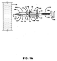
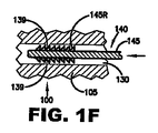
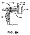
図1A〜図1Cは、それぞれ、初めの形態における本発明の締結具の第一の実施形態の側面図、正面図及び背面図を示している。締結具100は、壁の背後に(左に)中空空間を有する壁120(図1A)内に打ち込まれる。締結具100は、接合部108で当接しかつヒンジ115によって接合された壁アンカー部分105と回動可能な部分110とを備える。具体的に、図2A〜図2cの断面図に最善に示されているように、回動可能な部分110と壁板部分105は、アンカー100の底部中心で、一体又は「動作する」ヒンジ115又は回動点によって共に接合される。同様に、それらは、接合部108(斜線によって図示)で近接し、ここで、回動可能な部分110及び壁板セクション105は互いに隣接している。このように、部分110と105の隣接する部分の間に間隙はない。
Description of the first embodiment, FIGS. 1A-1G
1A to 1C respectively show a side view, a front view, and a rear view of a first embodiment of the fastener of the present invention in an initial form. The
ヒンジ115は、典型的であり、一体又は「動作する」ヒンジ、ストラップ、フラップ、ひも、ピンを有する二部分ヒンジ、又は他の種類の接続要素の形態をとることができる。回動可能な部分110は、使用者(図示せず)から遠位の鋭利な先端部112の前端部で終端する。壁アンカー部分105は、その後端部又は近位端部で平坦な頭部107で終端する。部分105と110の断面は、図1Bと図1Cの111で示したように、短軸及び長軸の比率が約0.6に等しい楕円形であることが好ましい。この比率は例示的であり、本出願によって決定される。他の軸比及び形状を使用することができる。
The
任意のフィン125は、先端部112から頭部107の底面に延びる。フィン126は、頭部107の底部の外縁から、壁アンカー部分105の長さにわたってフィン125に下方に延びる。丸い孔又は空洞130は、壁アンカー部分105を通して軸方向に延びる。代わりに、孔又は空洞130は、好ましい実施形態に関連して以下に述べるように、楕円形、長方形、及び他の形状を有することができる。
突出部135は、回動可能な部分110の部分であり、孔130の直径以上の距離だけ孔130に延び、一時的にそこに留まる。突出部135は、斜めの端部136及び丸い縁部137に終端する。
The
頭部107の底部側面からヒンジ115の支点までの部分105の長さは、壁120の厚さに等しいことが好ましく、一般に1〜2.5cmである。先端部分110の長さは約2.5cmであることが好ましい。このように、部分105と110の組み合わせ長さは、約4cmであることが好ましい。他の長さを設けることができ、使用すべき長さは壁の厚さに左右される。
The length of the
代わりに、壁板120の厚さを変更するために、単一長さの締結具を使用することができる。このことは、以下の図2Fと図2Gに関連してより詳細に説明する。
Alternatively, a single length fastener can be used to change the thickness of the
締結具100の直径は名目上約7mmである。孔130の直径は約4mmであることが好ましい。これらの直径は、締結具によって支持されるべき荷重、及び孔の寸法と所望の貫通の容易さに応じて変更することができる。孔130は、孔130の頂部、底部、又は側面に配置される単一の歯部であってもよく、ロック歯部又はリング139を収容する。代わりに、孔は、円周全体又はその任意の部分の周りに、孔130の直径を約3.5mmに局所的に狭めるリング又は環を備えることが可能である。ロック歯部139は、ねじ山を備える隆起部、又は以下に説明するようなピン140A〜140L(図1D−A〜図1D−J、図1E−A、及び図1E−B)のノッチに係合する。頭部分107の厚さは、約1mmであることが好ましい。
The diameter of the
締結具100は、ナイロンのようなプラスチックから製造されることが好ましいが、他のプラスチック、金属、及び堅木を含む他の多くの材料が適切である。
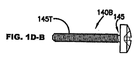
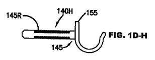
一般に、ノッチ付き、ラチェット付き、又はねじ付きシャフト145を含むピン140は、締結具100と共に供給されることが好ましい。ピン140は、孔130を通して完全に挿入されたときに締結具100を活動化させる。シャフト145は、一方の端部で面取り先端部150に、他方の端部でフック、ねじ頭、ボルトのような取付具155に終端する。
In general, a
ピン140は、ナイロンから製造されることが好ましいが、他のプラスチック、金属、及び木を含む他の材料を使用することができる。好ましい実施形態において、アンカーは、多数の異なる頭部を有しかつアンカー100と協働するように設計されたピンと共に供給される。
ピン140の様々な実施形態が図1DとEで示されている。それらのすべては、アンカー100と協働するようになっていて、また図1D−A〜図1D−Eのようなねじ山145Tを有するねじ又はボルト、図1D−F〜図1D−Jのような平頭、ねじ頭、ボルト頭、及びフックを含むノッチ145R及び様々な形状の頭部を有するピン、図1E−Aのような非円形の断面及びラチェットノッチ143を有するピン、又は図1E−Bのような大きなねじ山144であることができる。孔130の内部は、丸い断面以外の大きな又は小さなねじ山を含む少なくとも一つのおそらくは多くのピンシャフト設計、及び様々な直径を受け入れるように構成される。
Various embodiments of the
図1Fは、ピンシャフト145のラチェット歯部145Rに係合する締結具100の孔130内のロック歯部139の詳細を示している。ラチェット歯部145Rが図1Aと図1D−F〜図1D−Jに示されている。図1Aでは、歯部145Rは、ピン140のシャフト145の円周全体の周りに形成される。図1D−F〜図1D−Jでは、歯部145Rは、ピン140のシャフト145の円周全体未満の周りに選択的に形成される。ラチェット歯部143は、図1E−Aのピン140Kの少なくとも片側面に示されている。ピン140は、締結具100の孔130に挿入され、次に矢印の方向に押圧される。ラチェット歯部145Rは、ピン140が矢印の方向に押圧されるときにそれらのそれぞれの傾斜面に沿ってロック歯部139及びラチェット歯部145Rを曲げることによって、内部に柔軟に通過する。しかし、ピン140が反対方向に付勢されるとき、歯部145R及び歯部139の平行面が出会う。それらの歯部は、それらの平行面の反対側の傾斜を形成する材料によって支えられるので、矢印の反対方向に付勢されるときに、歯部ははるかに柔軟でない。このように、ピン140が締結具100に挿入されるとき、歯部145Rは、強制的にロックリング139に係合して、ピン140の引き抜きを防止する。
FIG. 1F shows details of the locking
図1Gは、締結具100の孔130に係合するピンシャフト145のねじ山145Tの詳細を示している(ねじ山145Tは、上に説明したねじ山144と較べて比較的小さい)。ねじ山145Tの直径は、孔130の内径よりも約10パーセント大きい。このように、ピン140が矢印の方向に孔130内にねじ込まれるにつれ、ねじ山145Tは締結具100の材料内に切り込まれる。ピン140が内部に前進するにつれ、ねじ山145Tはロックリング139内の材料を強制的に押し退けて、材料を大部分除去する。この押し退けは、ねじ山145Tと孔130の残部との間の摩擦力よりも、ねじ山145Tと以前にリング139を構成していた材料との間の摩擦力を高める。このように、ピン140のねじ付きの構造は、締結具100で再び確実に固定される。
FIG. 1G shows details of the
図2A〜図2G、図3A、図3Bは追加の任意の特徴を示している。ピン140L(図1E)の大きな雄ねじ山144を収容するために、締結具100の部分105内に大きな雌ねじ山200を加えることができる。
2A-2G, 3A, and 3B illustrate additional optional features. A large
第一の実施形態、操作、図2A〜図2G、準備
図2A〜図2Gは、締結具100の断面図を示している。締結具100には、図2Aに示したように、後部の固定部分105及び前部の回動可能な部分110が供給される。部分105と110が曲げられ軸方向整列から外れた場合、すなわち、それらが互いに対し角度を形成する場合(図示せず)、使用者は、それらを曲げてそれらの軸が整列されるようにしなければならない。
First Embodiment, Operation, FIGS. 2A-2G, Preparation FIGS. 2A-2G show cross-sectional views of
部分が整列されると、縁部137は孔130の表面と摩擦可能に擦れる。ヒンジ115の弾性により、これらの二つの表面の摩擦接触が可能である。部分105と110が軸方向整列から外れるか、あるいは曲げられて軸方向整列から外れており、次に、挿入の準備のために曲げ戻されて整列された場合、縁部137がスナップ作用で孔130の上方に移動する。このスナップ作用により、部分105と110の間の間隙なしに、締結具100は剛性的に直線状態に留まるようにされ、その間、締結具は壁板120内に打ち込まれる。この剛性は、締結具100が壁板120に入るとき、先端部112のふらつきを防止する。
When the portions are aligned, the
代わりに、部分105と110は、砕けやすい接合部108(図1A)によって製造時に融合することができる。この継手は、以下に述べるように、後にピン140の挿入によって破壊される。締結具100がプラスチックのような可撓性材料から製造されるならば、部分105と110は、僅かに屈曲することによって弾性を増す。
Alternatively,
挿入
次に、締結具100は、その楕円形断面111の主軸(図1Bと図1C)が水平であるように配向される。この配向により、壁板120内の荷重応答圧力が低減され、締結具100によって変形される壁板120内の面積が最小にされる。次に、締結具100は、ハンマー(図示せず)、あるいは他の鈍器又は親指によって壁板120内に打ち込まれる。ハンマーの打撃は、締結具100の軸に対し平行方向に頭部107の外面に適用される。代わりに、締結具100は、壁板120の穿孔された又は打ち抜かれた孔(図示せず)に挿入することができる。この場合、孔の直径は、部分105の最小半径以下であることが好ましい。
Insertion Next, the
締結具100が壁板120(図2B)に入るとき、任意のフィン125は、楕円形の断面111(図1B、図1C)の水平配向を正確に維持する。フィン125がない場合、先端部分110の本体が壁板120に入ると、楕円形断面111はアンカー110の回転を妨げる。
When the
部分110と105の隣接する縁部の間には間隙がないので、すなわち、それらは近接しているので、アンカーは、壁内に叩き込まれるときにその構造を保持する。このように、遠位及び近位部分は、図1Aに示したようなそれらの初めの形態に留まり、分離しないか又は互いに回動しない。対照的に、ある従来技術のアンカーでは、壁アンカー部分と回動可能な部分との間に間隙があったので、アンカーが壁内に叩き込まれたとき、その部分はしばしば分離し、壁を破損し、またアンカー全体を交換しなければならなかった。
Since there is no gap between adjacent edges of
図2Cは、壁板120に完全に埋設された締結具100を示している。頭部107の底面は、壁板120の外面に確実に支えられる。それらが壁板120に入るとき、フィン126は、締結具100の事前に決定された配向を維持する。締結具100が完全に挿入されるとき、図1Bと図1Cの111で示したフィン126及び部分105と110の楕円形断面は、荷重下又はトルクが締結具100に加えられるとき、例えば大きなねじが孔130内に取り付けられるときに、その回転も防止する。
FIG. 2C shows the
締結具100が完全に挿入されるとき(図2C)、ヒンジ115は壁板120の内部面に位置決めされる。頭部107の下面とヒンジ115との間の距離は、壁板120の厚さに従って選択される。米国では、壁板120は1.27cm〜2.54cmの範囲の標準厚さで供給される。このように、締結具100はまた、これらの厚さに合うために様々なヒンジと頭部の距離で供給される。
When the
代わりに、締結具100の部分105は、以下に説明するように、壁板120の厚さの範囲で使用するために単一の長さで供給することができる。
Alternatively, the
作動化
壁板に挿入された締結具を固定するために、ピン140は、締結具100の孔130に挿入される(図2D)。ピン140は、先端150が縁部136に衝突するまで手動で挿入される。図2Dに示したピンの代わりに、図1Dと図1Eに示した他の任意のピンが正確にアンカーと嵌合するように構成されることを前提として、それらのピンを使用することができる。
Activation To secure the fasteners inserted into the wallboard, the
ノッチ付き又はラチェット付きシャフト(140F〜140K、図1Dと図1E)の場合、別の挿入力が使用者の親指によって通常提供される。ねじ付きシャフト(140A〜140E、140L、図1Dと図1E)の場合、使用者の手又はねじ回し又はレンチ(図示せず)が使用される。両方の場合、ねじ山145T、144又はノッチ145R、143が係合して、上に説明したように、孔130のロック歯部139によって位置保持される。代わりに、ねじ山145Tと144は、ロック歯部130によって部分保持されることができる。これらのねじ付きピンはまた、ねじ山を使用して、孔130の内部からアンカー本体105を備える材料内に切り込み、これによってねじ山をアンカー材料内に確実に係合させ、同様に上に説明したように、ロックピン140を適所に固定する。先端部分110は壁板120内の材料に干渉しないか又はそれを押し退けないので、必要な挿入力は最小である。突出部135及び孔130の縁部137の摺動干渉によって形成される戻り止めのみを克服すればよい。ヒンジ115の弾性は、この摺動の発生を可能にする。
In the case of notched or ratcheted shafts (140F-140K, FIGS. 1D and 1E), another insertion force is usually provided by the user's thumb. In the case of threaded shafts (140A-140E, 140L, FIGS. 1D and 1E), the user's hand or screwdriver or wrench (not shown) is used. In both cases, the
ピン140の先端150を縁部136に押圧することにより、ヒンジ115を中心とする反時計回り(CCW)のトルクモーメントが生成され、すなわち先端150は、カムフォロワとして機能する縁部136に係合し、先端又は回動可能な部分110が最後に壁板120(図2E)の内面に確実に支えられるまで、それらが反時計回り(CCW)(図2D)に回転するようにさせる。アンカーは、今や、その作動する又は拡張した形態にあり、壁板内にまたその上に固定される。すなわち、ピン140が適所にある状態で、ねじ山145T、144、又はノッチ145R、143、及びロック歯139によってしっかりと保持されて、締結具100は壁板120に確実かつしっかりと据え付けられる。
By pressing the
今や、絵、鏡等(図示せず)をピン140のフックに掛けることができ、アンカーは、回動可能な部分110によって付与されるロック作用のため引き抜きに耐える。図1D−A〜図1D−Eのピン140A〜140Eのように、ピンがフックを有しない場合、ピンを最初に締結具100に完全に挿入し、締結具を作動化させ、次に2mmのオーダで引き抜いて、ピンのシャフトにワイヤ(図示せず)を掛けることを可能にすることができる。この小さな引き抜き距離は、締結具100を非作動化しない。
Now, a picture, mirror, etc. (not shown) can be hung on the hook of the
締結具100の部分105は、壁板120の厚さの範囲に使用するために単一の長さで供給することができ、次の二つの例が当てはまる。図2Fに示した第一の例では、部分105の長さは壁板120の厚さよりも大きい。突出部135は、先端部分110が90度よりも大きな円弧を実行するときにピン140が縁部136(図1A)と接触する程度に十分長く、最終的に壁板120の内側面に圧接する。
The
図2Gに示した第二の例では、部分105の長さは壁板120の厚さよりも小さい。突出部135、ヒンジ115、及びピン140は、ピン140が僅かに曲がり、突出部135を通過して押圧する程度に十分に可撓性であり、部分110を壁板120の内面に割り込ませる。
In the second example shown in FIG. 2G, the length of the
追加の利点は、締結具100の長円又は楕円形の断面から得られる。この非円形の形状は、円形状で可能であるよりも大きな回転トルクをピン140に適用することを可能にし、したがって、回転ブローアウトを低減する。
Additional advantages are obtained from the oval or elliptical cross section of the
図1E−Gは、ねじ山144を有し、締結具100(図2A)の孔130に挿入され、雄ねじ山144を締結具100内の雌のねじ山200に係合するために回転又はねじ込まれる、ピン140Lを示し、これによって締結具を作動化する。
FIGS. 1E-G have
本発明の締結具は、ピンの様々な寸法及び型式を受け入れ、これに対し、従来技術の締結具は、概ね、所定の寸法及び型式、すなわち、一定の直径及びピッチのねじ山を必要とする。 The fasteners of the present invention accept various pin sizes and types, whereas prior art fasteners generally require a predetermined size and type, i.e., constant diameter and pitch threads. .
第二の実施形態、説明及び操作、図3Aと図3B
第二の実施形態(図3)は、二つの回動先端部分110と110’を使用する。このような二つの部分を使用することによって、本実施形態は、壁板のより大きな面積に係合し、より強いアンカーをもたらす。部分110と110’の各々は、好ましい実施形態に関連して上述したように、ヒンジ115と115’それぞれによって壁アンカー部分105に接合される。ピン140の先端部150によって付勢された場合、突出部135と135’の縁部136と136’に対する力は、それらのそれぞれのヒンジの周りにトルクモーメントを形成し、部分110を上方に回動し、部分110’を下方に回動させる。
Second embodiment, description and operation, FIGS. 3A and 3B
The second embodiment (FIG. 3) uses two
ピン140が締結具100’に挿入されるとき、部分110と110’は壁板120の内部に確実に支えられ、ラチェット歯部又はノッチ145R又は143(図1Dと図1E)は、ロック歯部139によって保持され、これによって締結具100をしっかりと埋設する。
When the
ピン140の近位端部又はフックにかかる絵又は他の重量物は、締結具100の前部又は遠位端部が図3Bに示したように右回りに回転する傾向を有するように付勢する。しかし、先端部分110は、壁板120の内面に力を及ぼすことによって締結具100’の回転を防止する。先端部分110に及ぼされるすべての反時計回りトルクにより、ピン140の遠位端部は、突出部135と135’の間でさらに確実に挟持される。その結果、重量物がピン140にかけられるとき、締結具はよりしっかりする。
A picture or other heavy load on the proximal end or hook of the
第三の実施形態、説明及び操作、図4A、図4B、図5A〜図5C
第三の実施形態(図4)では、締結具100”は、二つの回動部分110”と110’”を使用する。本実施形態は、壁板120の厚さが、ヒンジ115と115’が壁板120内に位置する程度の厚さである場合に、有用である。この場合、部分110”と110’”は、部分が拡大されたときに部分の下の壁板120を局所的に圧縮して、強化するウェッジを備える。部分110”と110’”は対称の対を形成する。締結具100”が壁板120内に打ち込まれるとき、先端半部112’と112”は介入間隙なしに共に押圧され、また単一ユニットとして作用して、壁板120を通る直線通路に締結具100”を案内する。
Third embodiment, description and operation, FIGS. 4A, 4B, 5A-5C
In the third embodiment (FIG. 4), the
部分110”と110’”は、先端半部112’と112”と反対側の尖点400と405で終端する。ピン140が締結具100”に挿入されるとき、先端部150は、尖点400と405を押圧して、部分110”と110’”がヒンジ115と115’の周りに回動するようにする。ピン140が完全に挿入されるとき、回動部分110”と110’”は、締結具100”の軸から外側方向に押し出され、ラチェット歯部又はノッチ145R又は143(図1Dと図1E)は、ロック歯部139によって位置保持され、これによって締結体100”は壁板120の適所に確実に押し込まれる。
二つの回動可能な部分(110イ”と110’”)の代わりに、三つ以上の回動可能な部分を使用することができる。図5Aは、図4Aと図4Bと同様の締結具100”の先端部の図面を示している。図5Bと図5Cは、それぞれ三つ及び四つの回動可能な部分520、522、524、及び520’、522’と524’を示した先端部の図面である。円断面が示されているが、本実施形態はまた、楕円形断面を有することができる。
Instead of two pivotable parts (110 "" and 110 '"), three or more pivotable parts can be used. FIG. 5A shows a drawing of the tip of a
第四の実施形態、説明及び操作、図6Aと図6B
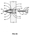
本実施形態(図6)では、ヒンジは使用されない。その代わりに、二つの回動部分が回動軸を中心に回転するようにされ、枢着軸は、挿入されたピンのラック(真っ直ぐなギヤ)によって回転されるそれぞれのピニオンギヤを保持する。締結具600には、一方の端部でピニオンギヤ605と610を有する二つのアーム602と604が取り付けられる。ギヤ605と610は、枢着軸615と620の壁締結具本体607に隣接して装着される。
Fourth embodiment, description and operation, FIGS. 6A and 6B
In this embodiment (FIG. 6), no hinge is used. Instead, the two pivot parts are adapted to rotate about the pivot axis, and the pivot shaft holds the respective pinion gear that is rotated by the rack of pins inserted (straight gear). Two
ピン組立体640は、その先端部650に隣接するラック645と、ラチェット歯部又はノッチ145R又は143(図1Dと図1E)とを含む。
アンカー600は、上述のように、壁板120内に打ち込まれ、先端半部630と635によって案内される。次に、ピン組立体640が締結具600の孔650に挿入される(図6B)。ピン640が挿入されるにつれ、ラック645は、ピニオン605と610に係合して、アーム602と604が締結具600の軸から離れて、外側方向に回動するようにする。ピン640が完全に挿入されるとき、アーム602と604は、壁板120の内面に確実に押し込まれ、ラチェット歯又はノッチ145R(143)は、ロック歯139によって位置保持され、締結具600のしっかりした固定をもたらす。
本実施形態は、壁から容易に取り除かれる。ピン640の引き抜きにより、アーム602と604の再整列が行われ、アンカー600の引き抜きを可能にする。
This embodiment is easily removed from the wall. Withdrawing
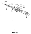
好ましい実施形態、説明及び操作、図7A〜図7I
本発明の好適な実施態様による締結具の斜視図が図7Aに示されている。締結具700の壁アンカー部分705は、一対のフィン710と頭部715とを有する本体を備える。回動可能な部分720は、突出部735の鋭利な先端部725と指部730とを備える。部分705と720は、先細りの楕円形断面を有し、動作ヒンジ740によって接合される。第一の実施形態に関連して上述したように、ヒンジ740は、代わりに、ストラップ、フラップ、ひも、ピンを有する二部分ヒンジ、又は他の種類の接続要素の形態をとることができる。
Preferred Embodiment, Description and Operation, FIGS. 7A-7I
A perspective view of a fastener according to a preferred embodiment of the present invention is shown in FIG. 7A. The
締結具700は、プラスチックから製造されることが好ましいが、上に説明したように、他の材料を使用することができる。二つの適切なプラスチックは、E.I.デュポンドゥ・ヌムール社、ウィルミントン、デラウェア、米国(E.I. DuPont de Nemours Company, Wilmington, Delaware, U.S.A)によって、「ナイロン6」及び「ナイロン66 Super Tough」の商標名で販売されている。
図7Bは、締結具700の断面図である。部分705の内部のノッチ745は、部分705と720が壁板120に挿入するために軸方向に整列されるとき、突出部735の指部730を受容する。部分705と720の整列は、挿入のため剛性である。挿入は、ハンマー、ねじ回しの取っ手のような打ち込み装置からの力、あるいは頭部715の後面又は近位面に加えられる親指からの手の圧力によって達成される。ロック歯部139は、この図に含まれていることに注意されたい。図1Dと図1Eに示した種類のピン140を使用すべき場合、歯部139が含まれる。ピン140が隆起部746(図7E)のみを含む場合、あるいは図7Eと7Fに関連して以下に述べるように、ピンシャフトがねじ付きである場合(図1D−A〜図1D−E、図1E−B)、歯部は必要とされない。
FIG. 7B is a cross-sectional view of the
図7Cは、壁アンカー部分705用に使用可能な様々な断面形状を示している。図7c−Aは、半径方向の楕円形延長部760を有する丸い又は楕円形の中心部分755を備える拡張可能な孔750を示している。整列フィン710も示されている。孔750の形状及び弾性により、締結具700は、図1Dと図1Eに示したように、多種多様な寸法及び断面形状を有するピンシャフトを受容できる。図7C−BはH形状の孔を示している。図7C−Cは楕円形の孔を示している。図7C−Dと図7C−Eは、楕円形及び平行六面体形状を組み合わせた他の孔を示している。
FIG. 7C shows various cross-sectional shapes that can be used for the
図7Dは、締結具700の部分720の楕円形断面111を示している。
FIG. 7D shows an
図7Eは、ピン140の挿入前に壁板120に埋設された締結具700を示している。ピン140は、後部フック155と、先端部150を有するシャフト145と、隆起部746とを備える。図1Dと図1Eに示したピン構造又はこれらの構造の変形の任意のものを使用することが可能で、ラチェット及びねじ山を有するピン構造を含む。
FIG. 7E shows the
図7Fは、壁板120に完全に挿入され、かつ使用準備ができている締結具700を示している。ピン140のシャフト145は、部分720をヒンジ115を中心に強制的に回転させる。シャフト145は、突出部735に確実に押し込まれて、部分720を壁板120の内側面に押圧する。ピン140のシャフト145の隆起部746は、確実にノッチ745に保持される。
FIG. 7F shows the
ノッチ745に係合するための隆起部746を設ける代わりに、ピン140(図1Dと図1E)の任意のものを挿入することができ、存在するならば、ロック歯部139(図7B)に係合する。
Instead of providing a
この場合、部分720が部分705の上方に配向されることに注意されたい。荷重がピン140のフック155にかかると、トルクモーメントが生じ、これによって部分705が壁板120内で回転するように付勢される。このトルクは、部分705で壁板120によって一部分、また壁板120の内面に支えられる部分720によって部分的に相殺される。この配向の力の分布は、アーム、即ち部分705の長さにより復元トルクをもたらし、締結具700に追加強度を付与する。
Note that in this case,
図7Gは、回動可能な部分720の先端部725に取り付けられた任意の金属先端部725’を示している。標準ドライウォールとは異なる特性を有する、例えば、より硬質、より軟質、より柔軟等である材料から壁板120が製造される場合、また硬質先端部が望まれる又は必要である場合、先端部725’を使用することが出来る。
FIG. 7G shows an
様々な先端形状が可能である。単純な点を有する釘状の先端部725’の代わりに、先端部725(図7A)と725’は、図7H−Aに示したようなスプーンチゼル形状、図7H−Bの湾曲したチゼルを有する二重釘頭部、図7H−Cの先鋭チゼル、図7H−Dの簡単なチゼル、又は図7H−Eに示したような槍状チゼル等をとることができる。 Various tip shapes are possible. Instead of a nail-like tip 725 'having a simple point, the tips 725 (Fig. 7A) and 725' are shaped like a spoon chisel as shown in Fig. 7H-A, the curved chisel of Fig. 7H-B. It can be a double nail head, a sharp chisel in FIGS. 7H-C, a simple chisel in FIGS. 7H-D, or a hooked chisel as shown in FIGS. 7H-E.
図7Iは、上記の設計の変形を示している。雄ねじ765が部分720に形成され、またドリル尖端部770がドリルとねじ山の組み合わせを形成するために選択的に加えられる。取り付けるために、部分705と720を同軸に整列して、締結具700が初めの形態で最初に配置される。先端部770は、アンカー700が取り付けられるべき壁(図示せず)に配置される。ねじ回し先端が孔750に挿入され、矢印780で示されるように(手動で又は電動工具で)回される。先端775は平坦な刃として示されているが、孔750に係合する任意の形状で十分である。壁アンカー部分705が壁板120(本図に図示せず)の表面に達すると、ねじ回し先端775が取り除かれ、使用者の親指又はハンマーによって締結具700が壁に押入される。締結具700が壁に最後に押入される前に、締結具を配向するために指針785が使用される。指針785が上向きに面している場合に、ピン140が取り付けられる時に、図7Fに示したように回動可能な部分720が上向きに回動する。前述のように、締結具700が壁板120に完全に挿入されると、フィン710は締結具の回転を防止する。
FIG. 7I shows a variation of the above design.
結論、展開、及び範囲
上記のことから読者は、本発明の締結システムが、物品を壁及び天井に確実に固定するための新規な方法及び装置を提供することを理解するであろう。締結具の本体はハンマー等を使用して壁に挿入できるので、締結具は予め作製された孔を必要としない。既存の孔が存在する場合、締結具は、使用者の親指による力により手で挿入することができる。次に、使用者は作動化ピンを差し込む。ピンは締結具を作動化させ、締結具を壁に確実に結合し、同様に、高級木工家具、鏡、絵等を装着するためのハンガーを提供する。ピンは、使用者の親指で押圧することによって、又は使用者の指又はねじ回し又はレンチで手動でねじ込むことによって、簡単な手作業で挿入することができる。
Conclusion, Deployment, and Scope From the foregoing, the reader will understand that the fastening system of the present invention provides a novel method and apparatus for securely securing articles to walls and ceilings. Because the fastener body can be inserted into the wall using a hammer or the like, the fastener does not require pre-made holes. If there is an existing hole, the fastener can be inserted by hand with the force of the user's thumb. The user then inserts the activation pin. The pins actuate the fasteners and securely connect the fasteners to the wall, as well as provide hangers for attaching high-end woodwork furniture, mirrors, pictures and the like. The pin can be inserted manually by pressing with the user's thumb or manually screwed with the user's finger or screwdriver or wrench.
本発明の締結具は、ある範囲の壁厚と協働する。壁が壁アンカー部分の長さよりも薄い場合、締結具の回動部分は、その動作ヒンジ、ストラップ、フラップ、ひも、又は他の種類の接続体の周りで回転して、壁の内面に出会う。壁が壁アンカー部分の長さより厚い場合、締結具の回動部分は、90度未満回転して、壁の内面に割り込む。 The fastener of the present invention works with a range of wall thicknesses. When the wall is thinner than the length of the wall anchor portion, the pivoting portion of the fastener rotates around its operating hinge, strap, flap, string, or other type of connection to meet the inner surface of the wall. If the wall is thicker than the length of the wall anchor portion, the pivoting portion of the fastener rotates less than 90 degrees and cuts into the inner surface of the wall.
締結具の楕円形断面は、有利に、締結具内の材料体積の強さを組み合わせて、壁材料に加えられる圧力を低減する。楕円形断面は、壁アンカー部分のフィンと組み合わせて、締結具の回転によって引き起こされる壁材料の破裂を防止するようにさらに作用する。 The oval cross section of the fastener advantageously combines the strength of the material volume within the fastener to reduce the pressure applied to the wall material. The oval cross section further acts in combination with the fins of the wall anchor portion to prevent wall material rupture caused by fastener rotation.
叩き込み中に締結具の前後部分に当接して、剛性固定することにより、締結具が壁に叩き込まれるときに、ぐらつき及びつぶれが防止される。図4A〜図6Bの実施形態において、複数のアームが間隙なしに最初に接触する。これらのアーム上の先端は、締結具がドライウォールを通して打ち込まれるときに共に押圧されたままであり、再度ぐらつき及びつぶれを防止する。 By abutting against the front and rear portions of the fastener during hitting and rigidly fixing, wobbling and crushing are prevented when the fastener is hit into the wall. In the embodiment of FIGS. 4A-6B, the arms first contact each other without a gap. The tips on these arms remain pressed together when the fastener is driven through the drywall, again preventing wobble and crushing.
様々なピン構造が可能である。単一の締結具本体は、様々な円形、長方形、及び楕円形の形状を組み合わせた拡張可能な孔に挿入される多数の異なるピンの種類を受け入れる。 Various pin structures are possible. A single fastener body accepts a number of different pin types that are inserted into expandable holes that combine a variety of circular, rectangular, and elliptical shapes.
上記の説明は多くの特徴を有するが、これらの特徴は、限定的でなく、単に例示的であると考慮されるべきである。多くの変化及び展開が可能である。 While the above description has many features, these features should be considered illustrative rather than limiting. Many changes and developments are possible.
例えば、先細りの楕円形断面の代わりに、先細りの長方形の星形、又は他の断面を使用できるであろう。フックのような取付点の代わりに、ピンは、コードの延長部を備えることができ、次に、コードを荷重の周りに結ぶことができる。回動部分の縁部は、カムフォロワ、指部、ノブ、突出部、ローブ等として知られている。 For example, instead of a tapered elliptical cross section, a tapered rectangular star or other cross section could be used. Instead of an attachment point such as a hook, the pin can be provided with an extension of the cord and then the cord can be tied around a load. The edges of the rotating part are known as cam followers, fingers, knobs, protrusions, lobes and the like.
本発明のシステムは、グラウンドアンカー設計の当業者に周知の要素を使用するが、本発明のシステムは、これらの要素を新規な方法で組み合わせて、従来発見されなかった新しい結果を生み出す。したがって、本発明の範囲は、例示した実施形態ではなく、添付の特許請求の範囲及びそれらの法律上の等価物によって決定されるべきである。 Although the system of the present invention uses elements well known to those skilled in the art of ground anchor design, the system of the present invention combines these elements in novel ways to produce new results not previously discovered. Accordingly, the scope of the invention should be determined not by the embodiments illustrated, but by the appended claims and their legal equivalents.
100 締結具
105 壁アンカー部分
107 頭部
108 接合部
110 回動可能な部分
111 長円部
112 先端部
115 ヒンジ
120 壁板
125 フィン
126 フィン
130 孔
135 突出部
136 端部
137 縁部
139 ロック歯
140 ピン
143 ラチェットノッチ
144 大きなねじ山
145 シャフト
150 先端部
155 取付具
200 ねじ山
400 尖点
405 尖点
410 ヒンジ
420 ヒンジ
520 回動可能な部分
522 回動可能な部分
524 回動可能な部分
526 回動可能な部分
600 締結具
602 アーム
604 アーム
605 ギヤ
607 本体
610 ギヤ
615 回動軸
620 回動軸
630 先端半部
635 先端半部
640 ピン
645 ラック
650 先端部
700 締結具
705 壁アンカー部分
710 フィン
715 頭部
720 回動可能な部分
725 先端部
730 指部
735 突出部
740 ヒンジ
745 ノッチ
746 隆起部
750 孔
755 孔中心
760 孔延長部
765 ねじ山
770 ドリル尖端部
775 ねじ回し
780 矢印
785 指針
DESCRIPTION OF
Claims (29)
遠位部分と近位部分とを包含し、前記遠位部分と近位部分とが初めの形態で同軸である細長い部材を具備する壁アンカーにおいて、
前記近位部分が、前記近位部分を通る孔を有し、前記初めの形態で前記遠位部分に面する縁部を有し、
前記遠位部分が前記近位部分に対して回動出来るように、前記遠位部分と前記近位部分とが回動可能に接合され、
前記遠位部分が鋭利な前端部、及び前記近位部分の前記縁部に面する前記前端部と反対側の縁部を有し、前記縁部がカムフォロワ部分を構成し、且つ前記アンカー部材が前記初めの形態である場合に、細長い作動部材が前記近位部分の前記孔を介して挿入される時に、前記作動部材が前記遠位部分を拡張される又は固定する形態まで強制的に前記近位部分から離すように回動させるために配置され、
前記壁アンカーが壁内に打ち込まれる時に、前記遠位部分と近位部分とが初めの形態を保持し、且つ前記拡張された形態になるまで離れて回動しないか又は分離しないように、前記アンカーが前記初めの形態にある時に前記遠位部分の前記縁部が前記近位部分の前記縁部に隣接する、
壁アンカー。 A wall anchor,
In a wall anchor comprising an elongate member including a distal portion and a proximal portion, the distal portion and the proximal portion being coaxial in the original form,
The proximal portion has a hole through the proximal portion and has an edge facing the distal portion in the initial configuration;
The distal portion and the proximal portion are pivotally joined so that the distal portion can pivot relative to the proximal portion;
The distal portion has a sharp front end and an edge opposite the front end facing the edge of the proximal portion, the edge comprises a cam follower portion, and the anchor member is When in the initial configuration, when an elongate actuation member is inserted through the hole in the proximal portion, the actuation member is forced to a configuration that expands or secures the distal portion. Arranged to rotate away from the position part,
So that when the wall anchor is driven into a wall, the distal and proximal portions retain their original configuration and do not pivot or separate apart until they are in the expanded configuration. The edge of the distal portion is adjacent to the edge of the proximal portion when the anchor is in the initial configuration;
Wall anchor.
遠位部分と近位部分とを有する細長い部材を具備する壁アンカーにおいて、
前記遠位部分が少なくとも二つのアームを包含し、前記アームが、鋭利な先端を備える先端部、及び旋回軸とカムフォロワとを備える回動端部を有し、前記アームが前記近位部分に対し回動出来るように、前記回動端は前記近位部分に回動可能に接合され、
前記アームと前記先端部とが互いに隣接し、且つ初めの形態で前記近位部分と軸方向に整列され、
前記近位部分が、前記近位部分を通る孔を有し、
これによって、前記壁アンカーは壁内に打ち込まれる時に前記初めの形態に留まり、前記作動部材が前記近位部分の前記孔を通して挿入され、前記カムフォロワに押し付けられる時に、前記アームは前記近位部分に対して拡張される又は固定する形態に回動し、これによって前記壁アンカーを前記壁に固定する、
壁アンカー。 A wall anchor,
In a wall anchor comprising an elongate member having a distal portion and a proximal portion,
The distal portion includes at least two arms, the arm having a tip with a sharp tip and a pivoting end with a pivot and a cam follower, the arm relative to the proximal portion The pivot end is pivotably joined to the proximal portion so that it can pivot;
The arm and the tip are adjacent to each other and are axially aligned with the proximal portion in an initial configuration;
The proximal portion has a hole through the proximal portion;
Thereby, the wall anchor remains in the initial configuration when driven into the wall, and when the actuating member is inserted through the hole in the proximal portion and pressed against the cam follower, the arm is attached to the proximal portion. Pivoting to a configuration that is expanded or secured to the wall anchor, thereby securing the wall anchor to the wall;
Wall anchor.
初めの同軸形態で隣接する遠位部分及び近位部分を有する壁アンカーを用意する段階であって、前記遠位部分が、一方の端部に鋭利な先端部を有し、他方の端部に前記近位部分と回動可能に接合され、前記近位部分が後端部及び孔を有する、壁アンカーを準備する段階と、
背後に中空体積を有する壁において位置を選択する段階と、
細長い作動部材を準備する段階と、
前記初めの形態において、前記後端部が前記アンカーによって前記壁と接触するまで、前記位置で前記壁に前記鋭利な先端部及び前記アンカーを通す段階と、
前記遠位部分が回動するまで前記作動部材を前記孔に挿入する段階と、
を含み、
これによって、前記作動部材が前記遠位部分を拡張させる又は固定する形態まで強制的に前記近位部分から離すように回動させる、方法。 A method for fixing an object on a wall,
Providing a wall anchor having adjacent distal and proximal portions in an initial coaxial configuration, wherein the distal portion has a sharp tip at one end and at the other end; Providing a wall anchor pivotally joined to the proximal portion, the proximal portion having a rear end and a hole;
Selecting a position in the wall having a hollow volume behind;
Providing an elongated actuating member;
Passing the sharp tip and the anchor through the wall at the position until the rear end contacts the wall by the anchor in the initial configuration;
Inserting the actuating member into the hole until the distal portion rotates;
Including
A method whereby the actuating member is pivoted away from the proximal portion to a configuration that expands or secures the distal portion.
遠位部分と近位部分とを有する細長い部材を具備する壁アンカーにおいて、
前記遠位部分が少なくとも二つのアームを包含し、前記アームが、鋭利な先端を有する先端部とピニオンギヤを有する旋回端部とを有し、前記アームが前記近位部分に対して回動出来るように前記旋回端部が前記近位部分に回動可能に接合され、
前記アームと前記先端部とが互いに隣接し、且つ初めの形態で前記近位部分と軸方向に整列され、
前記近位部分が、前記近位部分を貫通する孔を有し、
これによって、前記壁アンカーは壁内に打ち込まれる時に前記初めの形態に留まり、前記ラックギヤが前記近位部分の前記孔を介して挿入され、前記ピニオンギヤと噛み合う時に、前記アームは前記近位部分に対して拡張される又は固定する形態に回動し、これによって前記壁アンカーを前記壁に固定する、
壁アンカー。 A wall anchor,
In a wall anchor comprising an elongate member having a distal portion and a proximal portion,
The distal portion includes at least two arms, the arm having a tip having a sharp tip and a pivoting end having a pinion gear so that the arm can pivot relative to the proximal portion. The pivot end is pivotally joined to the proximal portion,
The arm and the tip are adjacent to each other and are axially aligned with the proximal portion in an initial configuration;
The proximal portion has a hole extending through the proximal portion;
Thereby, the wall anchor remains in the initial configuration when driven into the wall, and when the rack gear is inserted through the hole in the proximal portion and meshes with the pinion gear, the arm is in the proximal portion. Pivoting to a configuration that is expanded or secured to the wall anchor, thereby securing the wall anchor to the wall;
Wall anchor.
Applications Claiming Priority (2)
| Application Number | Priority Date | Filing Date | Title |
|---|---|---|---|
| US11/171,088 US8764364B2 (en) | 2004-03-24 | 2005-06-29 | System and methods for wall and ceiling fastening |
| PCT/US2006/024649 WO2007005345A2 (en) | 2005-06-29 | 2006-06-23 | System and methods for wall and ceiling fastening |
Publications (2)
| Publication Number | Publication Date |
|---|---|
| JP2009510338A true JP2009510338A (en) | 2009-03-12 |
| JP2009510338A5 JP2009510338A5 (en) | 2009-12-10 |
Family
ID=37604952
Family Applications (1)
| Application Number | Title | Priority Date | Filing Date |
|---|---|---|---|
| JP2008519432A Pending JP2009510338A (en) | 2005-06-29 | 2006-06-23 | System and method for fastening walls and ceilings |
Country Status (9)
| Country | Link |
|---|---|
| US (1) | US8764364B2 (en) |
| EP (1) | EP1937987A4 (en) |
| JP (1) | JP2009510338A (en) |
| KR (1) | KR20080059532A (en) |
| CN (1) | CN101542139B (en) |
| AU (1) | AU2006266199A1 (en) |
| CA (1) | CA2611444C (en) |
| NZ (1) | NZ564956A (en) |
| WO (1) | WO2007005345A2 (en) |
Cited By (1)
| Publication number | Priority date | Publication date | Assignee | Title |
|---|---|---|---|---|
| KR102192672B1 (en) * | 2020-06-29 | 2020-12-18 | 대원전기 주식회사 | Fixing pin for connecting safety line of electric pole and method for falling prevention of working on the electric pole using it |
Families Citing this family (34)
| Publication number | Priority date | Publication date | Assignee | Title |
|---|---|---|---|---|
| US7654781B2 (en) | 2002-12-11 | 2010-02-02 | Cobra Fixations Cie Ltee-Cobra Anchors Co., Ltd | Anchor for hollow walls |
| US8764364B2 (en) | 2004-03-24 | 2014-07-01 | Illinois Tool Works Inc. | System and methods for wall and ceiling fastening |
| US7752732B2 (en) * | 2006-05-18 | 2010-07-13 | International Patent Development Group, Llc | Anchoring fastener with movable binding member and method for anchoring an object |
| US8109705B1 (en) | 2007-02-23 | 2012-02-07 | Illinois Tool Works Inc. | Twist-lock anchoring fastener |
| US7850408B2 (en) * | 2008-03-03 | 2010-12-14 | Illinois Tool Works, Inc. | Hollow wall fastener |
| US8197169B2 (en) * | 2008-03-03 | 2012-06-12 | Illinois Tool Works Inc. | Hollow wall fastener |
| US7926772B2 (en) | 2008-03-26 | 2011-04-19 | Hardware Resources, Inc. | Bathroom fixture attachment device including a rotary coupling |
| US8011080B2 (en) * | 2008-09-14 | 2011-09-06 | International Patent Development Group, Llc | Hinged wall and ceiling anchor with fins and hinge |
| US8945184B2 (en) * | 2009-03-13 | 2015-02-03 | Spinal Simplicity Llc. | Interspinous process implant and fusion cage spacer |
| US20110104640A1 (en) * | 2009-11-05 | 2011-05-05 | Yan Pogorelsky | System and method for aligning teeth |
| US8491305B2 (en) * | 2009-11-05 | 2013-07-23 | Yan Pogorelsky | System and method for aligning teeth |
| US8419430B2 (en) * | 2009-11-05 | 2013-04-16 | Yan Pogorelsky | System and method for incrementally moving teeth |
| US8858143B2 (en) * | 2010-05-03 | 2014-10-14 | Black & Decker Inc. | Wall anchor |
| US8444358B2 (en) * | 2010-05-03 | 2013-05-21 | Black & Decker Inc. | Wall anchor |
| GB2484771B (en) | 2011-08-08 | 2012-10-10 | Stanley Pritchard Daykin | Fixing device |
| US8579570B2 (en) * | 2011-08-11 | 2013-11-12 | GM Global Technology Operations LLC | Fastener attaching a component to a panel |
| US9188142B2 (en) * | 2011-08-18 | 2015-11-17 | Empire Technology Development | Hinged arm mechanically activated fastener |
| DE102012204187A1 (en) * | 2012-01-25 | 2013-07-25 | Johnson Controls Gmbh | Fastening element and method for its assembly |
| FR3006933B1 (en) * | 2013-06-13 | 2015-12-04 | Illinois Tool Works | INDIRECT HOLD FIXING TOOL, PROPULSION MEMBER AND FIXING MEMBER HAVING THE SAME FOR THE TOOL, AND METHOD OF FASTENING A FASTENER |
| JP5840725B2 (en) * | 2014-04-21 | 2016-01-06 | 株式会社国盛化学 | rivet |
| US9273710B1 (en) * | 2014-09-09 | 2016-03-01 | Neo Mechanics Limited | Rapid mounting hollow wall anchor |
| GB2530303B (en) | 2014-09-18 | 2021-07-07 | Uk Building Products Ltd | Fixing system |
| WO2016057966A1 (en) | 2014-10-09 | 2016-04-14 | Declark Daniel Dale | Flush mount screw anchor |
| DE202014010156U1 (en) * | 2014-12-22 | 2016-03-24 | Ejot Baubefestigungen Gmbh | Fastening element for attaching attachments to insulated building walls |
| AU2016431876A1 (en) * | 2016-12-08 | 2019-07-25 | Cobra Fixations Cie Ltee - Cobra Anchors Co. Ltd. | Anchor assembly for fastener |
| CA2989037A1 (en) | 2016-12-22 | 2018-06-22 | The Hillman Group, Inc. | Hollow wall anchor |
| CN106969021A (en) * | 2017-04-20 | 2017-07-21 | 四川西普石油物资装备有限公司 | Engineering machinery fastener with locking functions |
| CN106996414A (en) * | 2017-04-20 | 2017-08-01 | 四川西普石油物资装备有限公司 | The method for solving engineering machinery connecting portion loose unloading |
| US11619252B2 (en) | 2018-12-01 | 2023-04-04 | The Hillman Group, Inc. | Wallboard anchor |
| PL4055284T3 (en) * | 2019-11-04 | 2023-11-27 | Bullfix Ltd. | Fixing device |
| CN111329732B (en) * | 2020-02-25 | 2022-04-12 | 米伦医疗科技(苏州)有限公司 | Pin for adjusting height of walking aid |
| EP4047265B1 (en) * | 2021-02-22 | 2023-08-02 | Johannes Jungel-Schmid | Suspension device for suspending objects |
| CN113464537A (en) * | 2021-07-21 | 2021-10-01 | 宁波九龙紧固件制造有限公司 | Hexagonal head bolt with hole and production process thereof |
| TWI825971B (en) * | 2022-09-01 | 2023-12-11 | 樹德科技大學 | Wall device capable of replacing object |
Citations (5)
| Publication number | Priority date | Publication date | Assignee | Title |
|---|---|---|---|---|
| US3188905A (en) * | 1962-04-03 | 1965-06-15 | David I Millet | Fastening device with pivotal locking means |
| JPS60245821A (en) * | 1984-05-11 | 1985-12-05 | イリノイ ツール ワークス インコーポレイテツド | Anchor with self-boring screw for wall body |
| JPH02501586A (en) * | 1986-09-04 | 1990-05-31 | メカニカル プラスチックス コーポレーション | fastener device |
| JPH0532813U (en) * | 1991-10-07 | 1993-04-30 | 田中 祥晴 | Foam concrete stopper |
| JPH05321917A (en) * | 1990-07-27 | 1993-12-07 | Illinois Tool Works Inc <Itw> | Fastener |
Family Cites Families (55)
| Publication number | Priority date | Publication date | Assignee | Title |
|---|---|---|---|---|
| US492418A (en) * | 1893-02-28 | Button | ||
| US638384A (en) * | 1899-05-09 | 1899-12-05 | George H Dyer | Self-locking bolt for buildings. |
| US868353A (en) * | 1907-01-07 | 1907-10-15 | Richard A Martin Jr | Railroad-spike. |
| US977795A (en) * | 1909-11-04 | 1910-12-06 | William Gronke | Railroad-spike. |
| US974391A (en) * | 1910-04-28 | 1910-11-01 | John L Jossart | Spike. |
| US1051893A (en) * | 1910-10-03 | 1913-02-04 | Carl Joseph | Fastener. |
| US1236293A (en) * | 1916-11-01 | 1917-08-07 | Frank Grosser | Railroad-spike. |
| US1452514A (en) * | 1922-07-06 | 1923-04-24 | Henry B Newhall | Bolt anchor |
| US2266892A (en) * | 1940-04-11 | 1941-12-23 | Anchoring device | |
| US2916235A (en) * | 1955-12-07 | 1959-12-08 | Nagel Siegfried Heinri Wilhelm | Article suspending hook structure |
| US3213745A (en) * | 1962-09-13 | 1965-10-26 | James E Dwyer | Anchoring socket for screw type fasteners |
| US3431813A (en) * | 1967-08-03 | 1969-03-11 | Kenneth C Johnson | Hollow wall fastener |
| US3550499A (en) * | 1969-02-28 | 1970-12-29 | Stanley D Eilenberger | Screw anchor |
| US3897035A (en) * | 1974-03-25 | 1975-07-29 | Knock N Lok International | Wall fastener |
| US3983779A (en) * | 1975-03-10 | 1976-10-05 | Eaton Corporation | Nail |
| US4022100A (en) * | 1975-08-13 | 1977-05-10 | Johnson Kenneth C | Fastener |
| AU510498B2 (en) * | 1976-09-15 | 1980-06-26 | Mechanical Plastics Corporation | Expansible fastener |
| US4196883A (en) * | 1977-12-22 | 1980-04-08 | Coats & Clark, Inc. | Hollow wall fastener |
| US4274324A (en) | 1978-04-18 | 1981-06-23 | Giannuzzi Louis | Hollow wall screw anchor |
| US4233881A (en) * | 1978-05-05 | 1980-11-18 | Carrier Vernon J | Wall fastener structure |
| DE2819862A1 (en) * | 1978-05-05 | 1979-11-08 | Hilti Ag | EXPANSION DOWEL FOR FASTENING BEHIND |
| US4322194A (en) * | 1979-09-12 | 1982-03-30 | Coats & Clark, Inc. | Wall anchor with self-drilling capability |
| US4500238A (en) * | 1982-09-27 | 1985-02-19 | Eustathios Vassiliou | Hollow wall anchor |
| US4662808A (en) * | 1985-10-02 | 1987-05-05 | Lee-Rowan Company | Wall anchor |
| US4669936A (en) * | 1985-10-02 | 1987-06-02 | Lee-Rowan Company | Back clip |
| US4989817A (en) * | 1986-01-02 | 1991-02-05 | Lee-Rowan Company | Wall bracket |
| US4902179A (en) * | 1987-07-08 | 1990-02-20 | Jtb, Inc. | Drywall fastener |
| USRE36622E (en) * | 1987-07-08 | 2000-03-21 | Hilti Aktiengesellschaft | Drywall fastener |
| US5037257A (en) * | 1990-09-11 | 1991-08-06 | Roll It Inc. | Wall plug and anchor assembly |
| DE4140512C1 (en) * | 1991-12-09 | 1993-04-08 | A. Raymond & Cie, Grenoble, Fr | |
| US5221167A (en) * | 1992-07-20 | 1993-06-22 | Diversified Fastening Systems, Inc. | Security head anchor |
| US5881982A (en) * | 1993-03-12 | 1999-03-16 | Hollingsworth; Don A. | Fastener for holding objects to a perforated wall |
| DE4320163C1 (en) * | 1993-06-18 | 1994-05-11 | Raymond A Gmbh & Co Kg | Metal dowel for anchoring in thin wall plate - comprises two bracing arms pressed together pointed at end to the driven into plate and firmly connected to one another at opposite head end |
| US5409336A (en) * | 1993-08-06 | 1995-04-25 | Jericevich; Anthony | Wall anchoring apparatus |
| US5447005A (en) * | 1993-11-22 | 1995-09-05 | Giannuzzi; Louis N. | Reverse wedge truss-forming wall anchor |
| US5533851A (en) * | 1994-09-30 | 1996-07-09 | Clairson, Inc. | Hollow wall anchor |
| US5855347A (en) * | 1996-07-18 | 1999-01-05 | Hollingsworth; Don A. | Fastener for holding items to a perforated wall |
| CA2252008A1 (en) | 1998-10-28 | 2000-04-28 | Cobra Fixations Cie Ltee - Cobra Anchors Co. Ltd. | Combination wall anchor and push support fastener |
| DE19915913C2 (en) * | 1999-04-08 | 2001-06-07 | Mey Klaus Peter | Variable stroke fastener |
| US6524044B1 (en) * | 1999-11-23 | 2003-02-25 | Wtpa, Incorporated | Fastener of high prevailing torque, pulling force, and stripping torque |
| US6435789B2 (en) * | 1999-12-21 | 2002-08-20 | Powers Fasteners | Self drilling swivel toggle anchor |
| US6494653B2 (en) * | 2001-04-17 | 2002-12-17 | Emerson Electric Company | Wall anchor |
| US6719512B2 (en) * | 2001-06-21 | 2004-04-13 | Black & Decker Inc. | Method and apparatus for fastening steel framing with nails |
| US6641107B1 (en) * | 2002-10-10 | 2003-11-04 | Peter G. Janssen | Tool-free hanging device |
| US7360746B2 (en) | 2003-09-17 | 2008-04-22 | Raymond Routhier | Asymmetric drive pin |
| US7001124B2 (en) * | 2004-02-05 | 2006-02-21 | Illinois Tool Works Inc. | Anchor |
| US8764364B2 (en) | 2004-03-24 | 2014-07-01 | Illinois Tool Works Inc. | System and methods for wall and ceiling fastening |
| US7118315B2 (en) * | 2005-01-24 | 2006-10-10 | Joker Industrial Co., Ltd. | Spike nail structure |
| DE202005011883U1 (en) | 2005-07-28 | 2005-10-20 | Huang, Ching-Yun, Shengang | Small rack for removable joining of hooks or informative signs, comprising openings with specifically shaped inner surfaces |
| US7752732B2 (en) * | 2006-05-18 | 2010-07-13 | International Patent Development Group, Llc | Anchoring fastener with movable binding member and method for anchoring an object |
| US8109705B1 (en) * | 2007-02-23 | 2012-02-07 | Illinois Tool Works Inc. | Twist-lock anchoring fastener |
| US7850408B2 (en) * | 2008-03-03 | 2010-12-14 | Illinois Tool Works, Inc. | Hollow wall fastener |
| US8197169B2 (en) * | 2008-03-03 | 2012-06-12 | Illinois Tool Works Inc. | Hollow wall fastener |
| US8011080B2 (en) * | 2008-09-14 | 2011-09-06 | International Patent Development Group, Llc | Hinged wall and ceiling anchor with fins and hinge |
| US8444358B2 (en) * | 2010-05-03 | 2013-05-21 | Black & Decker Inc. | Wall anchor |
-
2005
- 2005-06-29 US US11/171,088 patent/US8764364B2/en active Active
-
2006
- 2006-06-23 JP JP2008519432A patent/JP2009510338A/en active Pending
- 2006-06-23 WO PCT/US2006/024649 patent/WO2007005345A2/en active Application Filing
- 2006-06-23 NZ NZ564956A patent/NZ564956A/en unknown
- 2006-06-23 KR KR1020077030581A patent/KR20080059532A/en not_active Application Discontinuation
- 2006-06-23 AU AU2006266199A patent/AU2006266199A1/en not_active Abandoned
- 2006-06-23 EP EP06773921.9A patent/EP1937987A4/en not_active Withdrawn
- 2006-06-23 CN CN200680023213XA patent/CN101542139B/en active Active
- 2006-06-23 CA CA2611444A patent/CA2611444C/en active Active
Patent Citations (5)
| Publication number | Priority date | Publication date | Assignee | Title |
|---|---|---|---|---|
| US3188905A (en) * | 1962-04-03 | 1965-06-15 | David I Millet | Fastening device with pivotal locking means |
| JPS60245821A (en) * | 1984-05-11 | 1985-12-05 | イリノイ ツール ワークス インコーポレイテツド | Anchor with self-boring screw for wall body |
| JPH02501586A (en) * | 1986-09-04 | 1990-05-31 | メカニカル プラスチックス コーポレーション | fastener device |
| JPH05321917A (en) * | 1990-07-27 | 1993-12-07 | Illinois Tool Works Inc <Itw> | Fastener |
| JPH0532813U (en) * | 1991-10-07 | 1993-04-30 | 田中 祥晴 | Foam concrete stopper |
Cited By (1)
| Publication number | Priority date | Publication date | Assignee | Title |
|---|---|---|---|---|
| KR102192672B1 (en) * | 2020-06-29 | 2020-12-18 | 대원전기 주식회사 | Fixing pin for connecting safety line of electric pole and method for falling prevention of working on the electric pole using it |
Also Published As
| Publication number | Publication date |
|---|---|
| US8764364B2 (en) | 2014-07-01 |
| CN101542139A (en) | 2009-09-23 |
| EP1937987A2 (en) | 2008-07-02 |
| NZ564956A (en) | 2011-05-27 |
| WO2007005345A2 (en) | 2007-01-11 |
| CA2611444A1 (en) | 2007-01-11 |
| EP1937987A4 (en) | 2014-12-17 |
| WO2007005345A3 (en) | 2009-04-16 |
| KR20080059532A (en) | 2008-06-30 |
| US20060222474A1 (en) | 2006-10-05 |
| CA2611444C (en) | 2012-10-09 |
| CN101542139B (en) | 2013-07-17 |
| AU2006266199A1 (en) | 2007-01-11 |
Similar Documents
| Publication | Publication Date | Title |
|---|---|---|
| JP2009510338A (en) | System and method for fastening walls and ceilings | |
| US7752732B2 (en) | Anchoring fastener with movable binding member and method for anchoring an object | |
| TWI331190B (en) | Self-drilling or self-deploying hollow wall anchor | |
| US8109705B1 (en) | Twist-lock anchoring fastener | |
| US5147166A (en) | Wall anchor | |
| US6354779B1 (en) | Self-drilling anchor bolt | |
| US8011080B2 (en) | Hinged wall and ceiling anchor with fins and hinge | |
| US4196883A (en) | Hollow wall fastener | |
| US20080063488A1 (en) | Self-drilling wall anchor device | |
| US7850408B2 (en) | Hollow wall fastener | |
| US4283986A (en) | Self-penetrating wallboard anchor | |
| JP2008533412A (en) | Anchor assembly with toggle for hollow wall | |
| JPH05240223A (en) | Plastic anchoring plug | |
| TWI755464B (en) | Hollow wall anchor and method of installing hollow wall anchor to wall | |
| US20050214095A1 (en) | Wall and ceiling fastening system and methods therefor | |
| AU2011202674B2 (en) | System and methods for wall and ceiling fastening | |
| SK9792002A3 (en) | Plug to be fastened to hollow and solid building materials | |
| JP5123220B2 (en) | Expanding anchor |
Legal Events
| Date | Code | Title | Description |
|---|---|---|---|
| A521 | Request for written amendment filed |
Free format text: JAPANESE INTERMEDIATE CODE: A523 Effective date: 20090622 |
|
| A621 | Written request for application examination |
Free format text: JAPANESE INTERMEDIATE CODE: A621 Effective date: 20090622 |
|
| A521 | Request for written amendment filed |
Free format text: JAPANESE INTERMEDIATE CODE: A523 Effective date: 20100622 |
|
| A131 | Notification of reasons for refusal |
Free format text: JAPANESE INTERMEDIATE CODE: A131 Effective date: 20111220 |
|
| A977 | Report on retrieval |
Free format text: JAPANESE INTERMEDIATE CODE: A971007 Effective date: 20111222 |
|
| A521 | Request for written amendment filed |
Free format text: JAPANESE INTERMEDIATE CODE: A523 Effective date: 20120321 |
|
| A131 | Notification of reasons for refusal |
Free format text: JAPANESE INTERMEDIATE CODE: A131 Effective date: 20120925 |
|
| A601 | Written request for extension of time |
Free format text: JAPANESE INTERMEDIATE CODE: A601 Effective date: 20121221 |
|
| A02 | Decision of refusal |
Free format text: JAPANESE INTERMEDIATE CODE: A02 Effective date: 20130604 |