JP2009509191A - Display device - Google Patents
Display device Download PDFInfo
- Publication number
- JP2009509191A JP2009509191A JP2008530707A JP2008530707A JP2009509191A JP 2009509191 A JP2009509191 A JP 2009509191A JP 2008530707 A JP2008530707 A JP 2008530707A JP 2008530707 A JP2008530707 A JP 2008530707A JP 2009509191 A JP2009509191 A JP 2009509191A
- Authority
- JP
- Japan
- Prior art keywords
- display device
- angular distribution
- lcd panel
- sub
- section
- Prior art date
- Legal status (The legal status is an assumption and is not a legal conclusion. Google has not performed a legal analysis and makes no representation as to the accuracy of the status listed.)
- Granted
Links
- 238000009826 distribution Methods 0.000 claims abstract description 49
- 230000003213 activating effect Effects 0.000 claims description 3
- 230000009977 dual effect Effects 0.000 abstract description 3
- 238000000034 method Methods 0.000 description 4
- 230000011218 segmentation Effects 0.000 description 3
- 238000010586 diagram Methods 0.000 description 2
- 238000005192 partition Methods 0.000 description 2
- 238000003491 array Methods 0.000 description 1
- 230000004888 barrier function Effects 0.000 description 1
- 230000000903 blocking effect Effects 0.000 description 1
- 238000009792 diffusion process Methods 0.000 description 1
- 239000004973 liquid crystal related substance Substances 0.000 description 1
- 230000000007 visual effect Effects 0.000 description 1
Images


Classifications
-
- G—PHYSICS
- G02—OPTICS
- G02F—OPTICAL DEVICES OR ARRANGEMENTS FOR THE CONTROL OF LIGHT BY MODIFICATION OF THE OPTICAL PROPERTIES OF THE MEDIA OF THE ELEMENTS INVOLVED THEREIN; NON-LINEAR OPTICS; FREQUENCY-CHANGING OF LIGHT; OPTICAL LOGIC ELEMENTS; OPTICAL ANALOGUE/DIGITAL CONVERTERS
- G02F1/00—Devices or arrangements for the control of the intensity, colour, phase, polarisation or direction of light arriving from an independent light source, e.g. switching, gating or modulating; Non-linear optics
- G02F1/01—Devices or arrangements for the control of the intensity, colour, phase, polarisation or direction of light arriving from an independent light source, e.g. switching, gating or modulating; Non-linear optics for the control of the intensity, phase, polarisation or colour
- G02F1/13—Devices or arrangements for the control of the intensity, colour, phase, polarisation or direction of light arriving from an independent light source, e.g. switching, gating or modulating; Non-linear optics for the control of the intensity, phase, polarisation or colour based on liquid crystals, e.g. single liquid crystal display cells
- G02F1/1323—Arrangements for providing a switchable viewing angle
-
- B—PERFORMING OPERATIONS; TRANSPORTING
- B60—VEHICLES IN GENERAL
- B60K—ARRANGEMENT OR MOUNTING OF PROPULSION UNITS OR OF TRANSMISSIONS IN VEHICLES; ARRANGEMENT OR MOUNTING OF PLURAL DIVERSE PRIME-MOVERS IN VEHICLES; AUXILIARY DRIVES FOR VEHICLES; INSTRUMENTATION OR DASHBOARDS FOR VEHICLES; ARRANGEMENTS IN CONNECTION WITH COOLING, AIR INTAKE, GAS EXHAUST OR FUEL SUPPLY OF PROPULSION UNITS IN VEHICLES
- B60K35/00—Arrangement of adaptations of instruments
-
- B60K35/22—
-
- B60K35/654—
-
- B60K35/656—
-
- G—PHYSICS
- G02—OPTICS
- G02F—OPTICAL DEVICES OR ARRANGEMENTS FOR THE CONTROL OF LIGHT BY MODIFICATION OF THE OPTICAL PROPERTIES OF THE MEDIA OF THE ELEMENTS INVOLVED THEREIN; NON-LINEAR OPTICS; FREQUENCY-CHANGING OF LIGHT; OPTICAL LOGIC ELEMENTS; OPTICAL ANALOGUE/DIGITAL CONVERTERS
- G02F1/00—Devices or arrangements for the control of the intensity, colour, phase, polarisation or direction of light arriving from an independent light source, e.g. switching, gating or modulating; Non-linear optics
- G02F1/01—Devices or arrangements for the control of the intensity, colour, phase, polarisation or direction of light arriving from an independent light source, e.g. switching, gating or modulating; Non-linear optics for the control of the intensity, phase, polarisation or colour
- G02F1/13—Devices or arrangements for the control of the intensity, colour, phase, polarisation or direction of light arriving from an independent light source, e.g. switching, gating or modulating; Non-linear optics for the control of the intensity, phase, polarisation or colour based on liquid crystals, e.g. single liquid crystal display cells
- G02F1/133—Constructional arrangements; Operation of liquid crystal cells; Circuit arrangements
- G02F1/1333—Constructional arrangements; Manufacturing methods
- G02F1/1335—Structural association of cells with optical devices, e.g. polarisers or reflectors
- G02F1/1336—Illuminating devices
- G02F1/133615—Edge-illuminating devices, i.e. illuminating from the side
-
- B60K2360/1526—
-
- B—PERFORMING OPERATIONS; TRANSPORTING
- B60—VEHICLES IN GENERAL
- B60R—VEHICLES, VEHICLE FITTINGS, OR VEHICLE PARTS, NOT OTHERWISE PROVIDED FOR
- B60R11/00—Arrangements for holding or mounting articles, not otherwise provided for
- B60R2011/0001—Arrangements for holding or mounting articles, not otherwise provided for characterised by position
- B60R2011/0003—Arrangements for holding or mounting articles, not otherwise provided for characterised by position inside the vehicle
- B60R2011/0005—Dashboard
-
- G—PHYSICS
- G02—OPTICS
- G02B—OPTICAL ELEMENTS, SYSTEMS OR APPARATUS
- G02B6/00—Light guides; Structural details of arrangements comprising light guides and other optical elements, e.g. couplings
- G02B6/0001—Light guides; Structural details of arrangements comprising light guides and other optical elements, e.g. couplings specially adapted for lighting devices or systems
- G02B6/0011—Light guides; Structural details of arrangements comprising light guides and other optical elements, e.g. couplings specially adapted for lighting devices or systems the light guides being planar or of plate-like form
- G02B6/0033—Means for improving the coupling-out of light from the light guide
- G02B6/0035—Means for improving the coupling-out of light from the light guide provided on the surface of the light guide or in the bulk of it
- G02B6/004—Scattering dots or dot-like elements, e.g. microbeads, scattering particles, nanoparticles
- G02B6/0043—Scattering dots or dot-like elements, e.g. microbeads, scattering particles, nanoparticles provided on the surface of the light guide
-
- G—PHYSICS
- G02—OPTICS
- G02B—OPTICAL ELEMENTS, SYSTEMS OR APPARATUS
- G02B6/00—Light guides; Structural details of arrangements comprising light guides and other optical elements, e.g. couplings
- G02B6/0001—Light guides; Structural details of arrangements comprising light guides and other optical elements, e.g. couplings specially adapted for lighting devices or systems
- G02B6/0011—Light guides; Structural details of arrangements comprising light guides and other optical elements, e.g. couplings specially adapted for lighting devices or systems the light guides being planar or of plate-like form
- G02B6/0033—Means for improving the coupling-out of light from the light guide
- G02B6/005—Means for improving the coupling-out of light from the light guide provided by one optical element, or plurality thereof, placed on the light output side of the light guide
- G02B6/0051—Diffusing sheet or layer
-
- G—PHYSICS
- G02—OPTICS
- G02F—OPTICAL DEVICES OR ARRANGEMENTS FOR THE CONTROL OF LIGHT BY MODIFICATION OF THE OPTICAL PROPERTIES OF THE MEDIA OF THE ELEMENTS INVOLVED THEREIN; NON-LINEAR OPTICS; FREQUENCY-CHANGING OF LIGHT; OPTICAL LOGIC ELEMENTS; OPTICAL ANALOGUE/DIGITAL CONVERTERS
- G02F1/00—Devices or arrangements for the control of the intensity, colour, phase, polarisation or direction of light arriving from an independent light source, e.g. switching, gating or modulating; Non-linear optics
- G02F1/01—Devices or arrangements for the control of the intensity, colour, phase, polarisation or direction of light arriving from an independent light source, e.g. switching, gating or modulating; Non-linear optics for the control of the intensity, phase, polarisation or colour
- G02F1/13—Devices or arrangements for the control of the intensity, colour, phase, polarisation or direction of light arriving from an independent light source, e.g. switching, gating or modulating; Non-linear optics for the control of the intensity, phase, polarisation or colour based on liquid crystals, e.g. single liquid crystal display cells
- G02F1/133—Constructional arrangements; Operation of liquid crystal cells; Circuit arrangements
- G02F1/1333—Constructional arrangements; Manufacturing methods
- G02F1/133391—Constructional arrangement for sub-divided displays
Abstract
本発明は、表示面が第1及び第2副区分(10a、10b)に分割されるデュアルビュー表示装置に関する。異なる副区分に異なる角度分布(16a、16b、16a′、16b′)を有する光を供給するバックライト構成が用いられる。このことは、例えば、自動車の運転者には見えない、自動車内での表示の一部における映画又はコンピュータゲームウィンドウの表示を、低コストで可能にする。The present invention relates to a dual view display device in which a display surface is divided into first and second sub-sections (10a, 10b). A backlight arrangement is used that supplies light with different angular distributions (16a, 16b, 16a ′, 16b ′) to different sub-sections. This makes it possible, for example, to display a movie or a computer game window at a part of the display in the car, which is invisible to the driver of the car, at a low cost.
Description
本発明は、異なる視野角で異なる内容を表示することができ、LCDパネル及びバックライト構成を有する表示装置に関する。 The present invention relates to a display device that can display different contents at different viewing angles and has an LCD panel and a backlight configuration.
そのような装置については、国際公開第2004/088996A1号パンフレットに開示されている。このような装置は、自動立体視3Dディスプレイとして用いられるように意図され、LCDパネル及び切り換え可能バックライト構成を有し、そのバックライト構成は2つの異なる角度分布であって、一の角度分布はユーザの右目に内容を表示するのに適し、他の角度分布はユーザの左目に表示するのに適する、2つの異なる角度分布でバックライトを与えることができるものである。そのバックライトは2つの状態間で切り換えられ、同時に、LCDパネルは、右目コンテンツ表示及び左目コンテンツ表示の間で切り換えられる。 Such a device is disclosed in WO 2004/088996 A1. Such a device is intended to be used as an autostereoscopic 3D display and has an LCD panel and a switchable backlight configuration, the backlight configuration having two different angular distributions, one angular distribution being Suitable for displaying content to the user's right eye and other angle distributions suitable for displaying to the user's left eye can be backlit with two different angular distributions. The backlight is switched between two states, and at the same time the LCD panel is switched between right eye content display and left eye content display.
そのようなディスプレイの場合の短所は、情報のフリッカのない表示を得るためにLCDパネルに課せられる高速の条件である。
本発明の目的は、それ故、複雑性が低く、コストパフォーマンスの高い解決方法を提供することである。 The object of the present invention is therefore to provide a solution with low complexity and high cost performance.
この目的は、請求項1に記載したディスプレイ装置により達成される。より具体的には、そのディスプレイは、LCDパネル及びバックライト構成を有し、LCDパネルの第1副区分は第1画像を表示するように備えられ、LCDパネルの第2副区分は第2画像を表示するように備えられ、バックライト構成は、前記第1副区分において第1角度分布で光を出射するように備えられ、第2副区分において、第1角度分布と異なる第2角度分布で光を出射するように備えられている。このことは、LCDパネルに表示されるコンテンツが、例えば、左に及び右に表示されるように意図されている情報間で迅速に切り換えられる必要はないことを意味する。LCDパネルの条件は、それ故、ディスプレイ装置のコストを低く維持することである。 This object is achieved by a display device according to claim 1. More specifically, the display has an LCD panel and backlight configuration, the first sub-section of the LCD panel is provided to display the first image, and the second sub-section of the LCD panel is the second image. The backlight configuration is provided to emit light with a first angular distribution in the first sub-section, and with a second angular distribution different from the first angular distribution in the second sub-section. It is provided to emit light. This means that the content displayed on the LCD panel does not need to be quickly switched between information that is intended to be displayed on the left and on the right, for example. The condition of the LCD panel is therefore to keep the cost of the display device low.
好適な実施形態においては、バックライト構成は、第1又は第2角度分布で光を選択的に出射するように備えられているライトガイドと、第1LCDパネル副区分を覆う第1制御可能シャッタと、第2LCDパネル副区分を覆う第2制御可能シャッタと、を有し、第1モードで、第1シャッタを透過性にし、且つ第2シャッタを遮断するようにして、第1角度分布で光を出射し、第2モードで、第1シャッタを遮断し、且つ第2シャッタを透過性にするようにして、第2角度分布で光を出射するように備えられている。このことは、低コストを実施する発明の考え方の1つである。それらのシャッタは粗い画素を有することが可能であり、完全な遮断状態であることと完全な透過性状態であることとの間のみで切り換えられる必要があり、それ故、低コストを達成することが可能である。 In a preferred embodiment, the backlight arrangement includes a light guide that is provided to selectively emit light with a first or second angular distribution, and a first controllable shutter that covers the first LCD panel subsection. A second controllable shutter covering the second LCD panel sub-section, and in the first mode, the first shutter is transmissive and the second shutter is blocked, so that light is transmitted in a first angular distribution. In the second mode, the first shutter is shut off and the second shutter is made transmissive so that light is emitted with a second angular distribution. This is one of the ideas of the invention that implements low costs. Those shutters can have coarse pixels and need only be switched between being completely blocked and fully transmissive, thus achieving low cost Is possible.
第1角度分布は第1ランプをアクティブにすることにより出射されることが可能であり、第2角度分布を有する光は第2ランプをアクティブにすることにより出射されることが可能である。 The first angular distribution can be emitted by activating the first lamp, and the light having the second angular distribution can be emitted by activating the second lamp.
バックライト構成はまた、第3モードで、両方のシャッタを透過性にしながら、同時に両方の角度分布を有する光を出射することが可能である。そのディスプレイはまた、その場合、デュアルビュー機能を有することなく、即ち、異なる方向に異なる内容を表示することなく動作されることが可能である。 The backlight configuration can also emit light having both angular distributions in the third mode while making both shutters transparent. The display can then also be operated without having a dual view function, i.e. without displaying different content in different directions.
バックライト構成はまた、第3角度分布で光を選択的に出射するように備えられることが可能である。このことは、例えば、乗り物において、同乗者の異なる着座位置の方への表示の適応を可能にする。 A backlight configuration can also be provided to selectively emit light with a third angular distribution. This makes it possible, for example, to adapt the display towards different seating positions of the passenger in the vehicle.
代替の実施形態においては、バックライト構成は、第2角度分布で光を出射するように備えられているライトガイドと、第1LCDパネル副区分を覆い、その副区分における角度分布を第1角度分布に変える第1ディフューザと、を有することが可能である。この機能を実行するディフューザはまた、低コストで達成することが可能であり、また、制御可能であることが可能である。 In an alternative embodiment, the backlight arrangement covers a light guide provided to emit light with a second angular distribution and a first LCD panel subsection, and the angular distribution in that subsection is the first angular distribution. It is possible to have a first diffuser that changes to A diffuser that performs this function can also be achieved at low cost and can be controllable.
代替の実施形態においては、バックライト構成はまた、第2LCDパネル副区分を覆う第2制御可能ディフューザを有することが可能である。 In an alternative embodiment, the backlight configuration can also have a second controllable diffuser that covers the second LCD panel subsection.
LCDパネルは16:9のフォーマットを有し、第2副区分は4:3のフォーマットを有することが可能であり、第1副区分と第2副区分との間の区分は鉛直方向の境界により得られる。 The LCD panel has a 16: 9 format, the second sub-partition can have a 4: 3 format, and the part between the first and second sub-partitions depends on the vertical boundary. can get.
代替として、LCDパネルは4:3のフォーマットを有し、第2副区分は16:9のフォーマットを有することが可能であり、第1副区分と第2副区分との間の区分は水平方向の境界により得られる。 Alternatively, the LCD panel can have a 4: 3 format, the second sub-section can have a 16: 9 format, and the section between the first and second sub-sections is horizontal. Obtained by the boundary.
ディスプレイ装置は乗り物に搭載されることが可能であり、第1画像は乗り物の運転者用に意図され、第2画像はその乗り物の同乗者用に意図されることが可能である。 The display device can be mounted on a vehicle, the first image can be intended for the driver of the vehicle, and the second image can be intended for the passenger of the vehicle.
本発明の上記の及び他の特徴については、以下に詳述する実施形態を参照することにより明らかになり、理解することができる。 These and other features of the present invention will become apparent and understood by reference to the embodiments described in detail below.
図1は、本発明の実施形態にしたがったディスプレイ装置の正面図である。そのディスプレイ装置は、自動車のダッシュボードに設置されるように意図されることが可能である。そのディスプレイ装置は、ナビゲーションシステムマップ、自動車ユーザ用インタフェース、又は運転者に対する何れかの他の運転に関する視覚情報等のナビゲーション情報を提供することができる。同時に、ディスプレイ装置は、映画、インターネットブラウザウィンドウ又はコンピュータゲームビュー等の、自動車の同乗者への他の情報を提供することができる。同乗者向け情報は、自動車を運転しているときには、安全のために、運転者には見えないようにする必要がある。同乗者は、同乗者向け情報のみ、又は同乗者向け情報及び運転者向け情報の両方を見ることが可能である。 FIG. 1 is a front view of a display device according to an embodiment of the present invention. The display device can be intended to be installed on the dashboard of an automobile. The display device can provide navigation information such as navigation system maps, car user interfaces, or visual information regarding any other driving to the driver. At the same time, the display device can provide other information to the passengers of the car, such as a movie, Internet browser window or computer game view. Passenger information needs to be hidden from the driver for safety reasons when driving a car. The passenger can see only the information for the passenger, or both the information for the passenger and the information for the driver.
従来技術においては、このことは、ディスプレイの全体の面に亘って1つの視野角で運転者向け情報を表示するディスプレイ装置を備える一方、他の視野角でディスプレイの全体の面に亘って同乗者向け情報を表示することにより対処されてきた。それらのデュアルビューディスプレイは、長い鉛直方向のバリア又はレンズアレイを用いることにより、自動立体視(3D)ディスプレイと多くの点で同じ様式で、大部分が得られている。 In the prior art, this includes a display device that displays information for the driver at one viewing angle over the entire surface of the display, while the passenger is traveling over the entire surface of the display at the other viewing angle. It has been dealt with by displaying information. These dual-view displays are largely obtained in many ways in the same manner as autostereoscopic (3D) displays by using long vertical barriers or lens arrays.
本発明の実施形態においては、しかしながら、ディスプレイ装置は、運転者向け情報の表示を意図された第1部分10aと、同乗者向け情報の表示を意図された第2部分10bとに分割されている。この構成は、特にコストの観点から有利点を与えるものであり、これについては下記で更に詳細に説明する。
In the embodiment of the present invention, however, the display device is divided into a
図2a乃至2cは、3つの異なる表示モードにおける、本発明の第1実施形態にしたがったディスプレイ装置の模式的断面図である。それらの断面は、図1を下方から見ることにより得られる。 2a to 2c are schematic cross-sectional views of the display device according to the first embodiment of the present invention in three different display modes. Their cross section is obtained by looking at FIG. 1 from below.
手短にいうと、ディスプレイ装置は、透過性LCDパネル10及びバックライト構成12を有する。
In short, the display device has a
LCDパネル10は、当該技術分野において知られているように、偏光子等としての複数の副層を有する。上記のように、第1区分10a及び第2区分10bは、運転者向け情報及び同乗者向け情報のそれぞれを表示するように備えられている。
As is known in the art, the
バックライト構成12は、第1角度分布又は第2角度分布を有する光を選択的に出射することができるライトガイド11を有する。
The
図2aは、第1モード(モードA)にあるディスプレイ装置を示している。ライトガイドは、国際公開第2004/088996A1号パンフレットに開示されているものと同様であることが可能である。その場合、モードAにあるライトガイド11が図2aに示すような第1光源18からの光で照明されるとき、そのライトガイドは第1角度分布16aで光を出射する。光源18は、例えば、1つ又はそれ以上の冷陰極蛍光ランプ又は発光ダイオード(LED)を有することが可能である。
FIG. 2a shows the display device in the first mode (mode A). The light guide can be similar to that disclosed in WO 2004/088996 A1. In that case, when the
バックライト構成12は、第1LCDパネル副区分10aを覆う第1制御可能シャッタ14aと、第2LCDパネル副区分10bを覆う第2制御可能シャッタ14bと、を更に有する。それらのシャッタ14a、14b自体は、知られている液晶用シャッタであることが可能である。モードAにおいては、第1シャッタ14aは透過性である一方、第2シャッタ14bは遮断されている。それ故、第1LCDパネル副区分10aは、第1角度分布16aを有する光で照明され、その第1角度分布16aは、例えば、運転者の位置において、ディスプレイ装置に関して第1角度位置からの画像を見るのに適することが可能である。
The
図2bは、第2モード(モードB)にあるディスプレイ装置を示している。このモードにおいては、ライトガイド11は、第1光源18の位置と異なるライトガイドに対する位置を有する第2光源20により照明されるように意図されている。このことは、第2角度分布で光を出射する、即ち、第1角度分布16aとは異なるライトガイドをもたらす。
FIG. 2b shows the display device in the second mode (mode B). In this mode, the
同時に、第1シャッタ14aは遮断され、第2シャッタ14bは透過性にされる。それ故、第2画像副区分は、第2角度分布16bを有する光により照明され、その第2角度分布16bは、例えば、同乗者の位置において、ディスプレイ装置に関して第2角度位置から画像を見るのに適することが可能である。
At the same time, the
ディスプレイ装置は、モードA及びモードB間で迅速に変わり、一の方向において副区分10aの内容を、そして他の方向において副区分10bの内容を表示することが可能である。このことは、LCDパネル副区分10a、10bにおいて表示される実際の内容を迅速に変えることなく行われ、そのことは、必要なLCDパネルの性能が低いまま維持され、その結果、比較的安価なディスプレイ装置を得ることができることを意味する。シャッタは、勿論、高速切り替えを可能にするが、それらのシャッタの要素は、遮断と完全な透過性との間のみで切り換えられるため、そしてそれらはかなり粗い画素を有することが可能であるため、それらは比較的安価である。
The display device can quickly change between mode A and mode B and can display the contents of the
自動車が停止し、運転者が交通環境に注意を集中する必要がないとき、図2cに示すように、第3モード(モードC)でのディスプレイ装置の駆動が適切であることがある。このモードにおいては、第1シャッタ14a及び第2シャッタ14bの両方が透過性であり、第1光源及び第2光源の両方がライトガイド11を照明している。ライトガイドは、それ故、両方の角度分布で、即ち、それら2つの分布の合計で同時に、光を出射する。運転者及び同乗者の両者は、それ故、全体の表示領域を見ることが可能である。2つの副区分は尚も、異なる内容を表示することが可能であるが、ディスプレイ全体に亘って1つの画像を表示することがまた、可能である。光源の電力又はLCDパネルの輝度は、シャッタを通る増加した平均の光強度を補償するように調整されることが可能である。図2cに示している第3モードは、運転者関連の情報が全体の表示領域に亘って表示されている限り、自動車を運転しているときに用いられることがまた、可能である。
When the vehicle is stopped and the driver does not need to focus attention on the traffic environment, driving the display device in the third mode (mode C) may be appropriate as shown in FIG. 2c. In this mode, both the
上記の実施形態に関連して、ライトガイド11及び光源18、20が、第1角度分布又は第2角度分布を有する光を選択的に出射することができる他の構成と置き換えられることが可能であることに留意されたい。第1シャッタ14aは、原理的に削除されることが可能であり、それ故、同乗者が第1副区分の内容を見ることをまた、可能にすることにまた、留意されたい。
In connection with the above embodiment, the
図2a乃至2cに関連して開示している実施形態においては、ライトガイド11と対向する第3の位置関係を有する、参照番号18及び20以外の更なる光源又は光源の集合が適用されることが可能である。このことは、第3角度分布を有する光がそのバックライト構成により出射されることを可能にし、そのことは、フレキシビリティの点で有用である。光の出射は、その場合、例えば、自動車において、同乗者が着座しているところに応じて調整されることが可能である。
In the embodiment disclosed in connection with FIGS. 2a to 2c, a further light source or set of light sources other than
図3a及び3bは、2つの異なる表示モードにおいて本発明の第2実施形態にしたがったディスプレイ装置の類似する断面を模式的に示している。この実施形態においては、ライトガイド11′は、少なくとも1つの光源20′により常に照明される。ライトガイド11′は又、それ故、一定の角度分布16b′を有する光を出射し、その一定の角度分布16b′は、同乗者の方に画像を表示するのに適することが可能である。LCDパネルの第2副区分10bにおいては、ディスプレイ装置は、それ故、ディスプレイ装置に対向する特定の角度関係を有する位置からのみ見ることが可能である画像を表示する。第1LCDパネル副区分においては、しかしながら、ディフューザ22は、光の角度分布を他の分布16′に変え、それ故、第1LCDパネル副区分10aは、第2副区分10bより広い角度範囲で見ることができる画像を表示する。表示領域のこの部分に表示される情報は、それ故、例えば、運転者がまた、見ることができる。
3a and 3b schematically show similar cross sections of a display device according to a second embodiment of the invention in two different display modes. In this embodiment, the light guide 11 'is always illuminated by at least one light source 20'. The light guide 11 'therefore also emits light having a constant
図3bに示しているように、ディフューザは切り換え可能であり、それ故、ディフュージング特性は低下される又は削除されることが可能である。それ故、例えば、運転者には表示される画像が全く見えないようにすることが可能である。勿論、第2副区分において制御可能ディフューザ(図示せず)を適用することがまた、可能である。 As shown in FIG. 3b, the diffuser is switchable, so that the diffusion characteristics can be reduced or eliminated. Therefore, for example, it is possible to make the displayed image completely invisible to the driver. Of course, it is also possible to apply a controllable diffuser (not shown) in the second subsection.
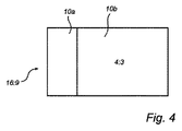
図4は、自動車用アプリケーションにおけるディスプレイ装置の区分化の第1方法を示している。この場合、標準的なワイドスクリーンフォーマット16:9(幅:高さ)を有するディスプレイが用いられている。同乗者向け使用が意図されている第2副区分10bは、鉛直方向の境界を適用することによりディスプレイの一方側において4:3の領域として得られる。その境界の他方側におけるディスプレイの残りの部分は、運転者向け情報を表示するように意図された第1副区分10aとして用いられる。
FIG. 4 shows a first method for segmentation of display devices in automotive applications. In this case, a display having a standard wide screen format 16: 9 (width: height) is used. The
図5は、自動車用アプリケーションにおけるディスプレイ装置の区分化の第2方法を示している。この場合、標準的なフォーマット4:3を有するディスプレイが用いられる。
同乗者向け使用が意図されている第2副区分10bは、水平方向の境界を適用することによりディスプレイの上方側又は下方側において16:9の領域として得られる。その境界の他方側におけるディスプレイの残りの部分は、運転者向け情報を表示するように意図された第1副区分10aとして用いられる。それ故、図4及び図5に示す区分化スキームは、同乗者が標準的な4:3又は16:9のフォーマットで映像を見ることを可能にする。
FIG. 5 shows a second method of segmentation of display devices in automotive applications. In this case, a display having the standard format 4: 3 is used.
The
要約すると、本発明は、表示面を第1副区分及び第2副区分に分割するデュアルビューディスプレイ装置に関する。異なる副区分に対して異なる角度分布を有する光を供給するバックライト構成が用いられる。このことは、低コストで、例えば、自動車において、一部がその自動車の運転者にとって見ることが可能でないディスプレイの一部に、映画又はコンピュータゲームウィンドウの表示を可能にする。 In summary, the present invention relates to a dual view display device that divides a display surface into a first sub-section and a second sub-section. A backlight configuration is used that supplies light with different angular distributions for different sub-sections. This makes it possible to display a movie or computer game window on a part of a display that is low cost, for example in a car, some of which is not visible to the car driver.
本発明は、上記の実施形態に限定だれるものではない。本発明は、同時提出の特許請求の範囲における範囲内で異なる方法で変えられることが可能である。 The present invention is not limited to the above embodiment. The present invention can be varied in different ways within the scope of the appended claims.
Claims (11)
前記LCDパネルの第1副区分は第1画像を表示するように備えられ、前記LCDパネルの第2副区分は第2画像を表示するように備えられ;
前記バックライト構成は、前記第1副区分において、第1角度分布で光を出射するように備えられ、前記第2副区分において、前記第1角度分布と異なる第2角度分布で光を出射するように備えられている;
表示装置。 A display device capable of displaying different contents at different viewing angles and having an LCD panel and backlight configuration:
A first subsection of the LCD panel is provided for displaying a first image, and a second subsection of the LCD panel is provided for displaying a second image;
The backlight configuration is arranged to emit light with a first angular distribution in the first subsection, and emit light with a second angular distribution different from the first angular distribution in the second subsection. Is equipped with;
Display device.
Applications Claiming Priority (3)
| Application Number | Priority Date | Filing Date | Title |
|---|---|---|---|
| EP05108700.5 | 2005-09-21 | ||
| EP05108700 | 2005-09-21 | ||
| PCT/IB2006/053251 WO2007034370A2 (en) | 2005-09-21 | 2006-09-13 | Display device |
Publications (2)
| Publication Number | Publication Date |
|---|---|
| JP2009509191A true JP2009509191A (en) | 2009-03-05 |
| JP5311471B2 JP5311471B2 (en) | 2013-10-09 |
Family
ID=37889195
Family Applications (1)
| Application Number | Title | Priority Date | Filing Date |
|---|---|---|---|
| JP2008530707A Expired - Fee Related JP5311471B2 (en) | 2005-09-21 | 2006-09-13 | Display device |
Country Status (5)
| Country | Link |
|---|---|
| US (1) | US9411181B2 (en) |
| EP (1) | EP1929355B1 (en) |
| JP (1) | JP5311471B2 (en) |
| CN (1) | CN101379429B (en) |
| WO (1) | WO2007034370A2 (en) |
Cited By (3)
| Publication number | Priority date | Publication date | Assignee | Title |
|---|---|---|---|---|
| JP2011100724A (en) * | 2009-10-09 | 2011-05-19 | Mitsubishi Rayon Co Ltd | Image display device |
| JP2016099477A (en) * | 2014-11-20 | 2016-05-30 | パイオニア株式会社 | Projection device, projection method, program, and storage medium |
| KR20190115115A (en) * | 2017-04-02 | 2019-10-10 | 레이아 인코포레이티드 | Dual View Zone Backlight, Dual-Mode Display, and Method |
Families Citing this family (17)
| Publication number | Priority date | Publication date | Assignee | Title |
|---|---|---|---|---|
| GB2460802B (en) * | 2007-03-20 | 2012-09-05 | Prysm Inc | Delivering and displaying advertisment or other application data to display systems |
| JP2012503818A (en) * | 2008-09-25 | 2012-02-09 | パナソニック オートモーティブ システムズ カンパニー オブ アメリカ ディビジョン オブ パナソニック コーポレイション オブ ノース アメリカ | Dual view touch screen display system and method of operation |
| WO2010040384A1 (en) * | 2008-10-07 | 2010-04-15 | Tomtom International B.V. | Navigation apparatus having a three-dimensional display |
| WO2010110786A1 (en) * | 2009-03-24 | 2010-09-30 | Hewlett-Packard Development Company, L.P. | Performing remoting operations for different regions of a display surface at different rates |
| DE112010004843A5 (en) * | 2009-12-18 | 2012-09-27 | Daimler Ag | DISPLAY METHOD AND DISPLAY DEVICE FOR A VEHICLE |
| DE102009058887A1 (en) * | 2009-12-18 | 2011-06-22 | Daimler AG, 70327 | Method for displaying information content e.g. video information of motor vehicle on LCD, involves adjusting brightness values of content based on environmental condition, and representing adjusted brightness values on display surface |
| US20110304597A1 (en) * | 2010-06-09 | 2011-12-15 | Apple Inc. | Low power backlight for display |
| US20120032872A1 (en) * | 2010-08-09 | 2012-02-09 | Delphi Technologies, Inc. | Dual view display system |
| DE102010043005A1 (en) * | 2010-10-27 | 2012-05-03 | Epson Imaging Devices Corp. | Device for controlling a display and display with a device for driving |
| DE102011007518A1 (en) * | 2011-04-15 | 2012-10-18 | Robert Bosch Gmbh | Display device for use in passenger car for displaying vehicle settings, has display comprising dual/split view mode that provides two images simultaneously and each display image individually visible from multiple view points |
| DE102012005858A1 (en) * | 2012-03-22 | 2013-09-26 | Audi Ag | Method for reproducing information in a motor vehicle |
| US10289260B2 (en) | 2014-08-27 | 2019-05-14 | Honda Motor Co., Ltd. | Systems and techniques for application multi-tasking |
| CN106020661B (en) | 2014-12-31 | 2020-11-24 | 本田技研工业株式会社 | Track pad with internal bezel |
| KR20160103601A (en) * | 2015-02-24 | 2016-09-02 | 삼성디스플레이 주식회사 | Display apparatus |
| US10402161B2 (en) | 2016-11-13 | 2019-09-03 | Honda Motor Co., Ltd. | Human-vehicle interaction |
| KR102437389B1 (en) * | 2016-12-13 | 2022-08-26 | 엘지디스플레이 주식회사 | Liquid crystal display device |
| CA3130749C (en) | 2019-03-17 | 2023-10-31 | Leia Inc. | Dual view zone backlight, dual-mode display, and method employing directional emitters |
Citations (5)
| Publication number | Priority date | Publication date | Assignee | Title |
|---|---|---|---|---|
| JPH11273438A (en) * | 1998-03-25 | 1999-10-08 | Enplas Corp | Sidelight surface light source device and liquid crystal display device |
| JP2002099223A (en) * | 2000-09-21 | 2002-04-05 | Sharp Corp | Display device |
| JP2003015535A (en) * | 2001-07-03 | 2003-01-17 | Alpine Electronics Inc | Display device |
| JP2005024737A (en) * | 2003-06-30 | 2005-01-27 | Optrex Corp | Liquid crystal display and its displaying method |
| JP2005257756A (en) * | 2004-03-09 | 2005-09-22 | Optrex Corp | Display apparatus |
Family Cites Families (12)
| Publication number | Priority date | Publication date | Assignee | Title |
|---|---|---|---|---|
| US5371510A (en) * | 1990-11-28 | 1994-12-06 | Nippondenso Co., Ltd. | Automotive information display apparatus |
| US5897184A (en) * | 1996-07-02 | 1999-04-27 | Dimension Technologies, Inc. | Reduced-thickness backlighter for autostereoscopic display and display using the backlighter |
| DE19735177C2 (en) | 1997-08-14 | 1999-07-01 | Mannesmann Vdo Ag | Display unit provided for fastening in a motor vehicle |
| DE19746764B4 (en) | 1997-10-23 | 2006-09-14 | Siemens Ag | display unit |
| JP2000098299A (en) | 1998-09-18 | 2000-04-07 | Sanyo Electric Co Ltd | Stereoscopic video display device |
| DE19925985A1 (en) | 1999-06-08 | 2000-12-14 | Bosch Gmbh Robert | Liquid crystal display with changeable viewing angle has electrically driven individual image element zones; different zones of image element can be selected via different column lines |
| GB0119176D0 (en) | 2001-08-06 | 2001-09-26 | Ocuity Ltd | Optical switching apparatus |
| JP3733889B2 (en) | 2001-10-05 | 2006-01-11 | 日産自動車株式会社 | Display device |
| JP2002228466A (en) | 2001-11-08 | 2002-08-14 | Sony Corp | Navigation system |
| EP1462297A3 (en) * | 2003-03-26 | 2007-05-09 | Calsonic Kansei Corporation | Information displaying apparatus for a vehicle |
| WO2004088996A1 (en) | 2003-03-31 | 2004-10-14 | Koninklijke Philips Electronics N.V. | Display device and method of displaying data thereon |
| GB2404991A (en) | 2003-08-09 | 2005-02-16 | Sharp Kk | LCD device having at least one viewing window |
-
2006
- 2006-09-13 US US12/067,304 patent/US9411181B2/en not_active Expired - Fee Related
- 2006-09-13 JP JP2008530707A patent/JP5311471B2/en not_active Expired - Fee Related
- 2006-09-13 CN CN2006800347773A patent/CN101379429B/en not_active Expired - Fee Related
- 2006-09-13 EP EP06796014.6A patent/EP1929355B1/en not_active Not-in-force
- 2006-09-13 WO PCT/IB2006/053251 patent/WO2007034370A2/en active Application Filing
Patent Citations (5)
| Publication number | Priority date | Publication date | Assignee | Title |
|---|---|---|---|---|
| JPH11273438A (en) * | 1998-03-25 | 1999-10-08 | Enplas Corp | Sidelight surface light source device and liquid crystal display device |
| JP2002099223A (en) * | 2000-09-21 | 2002-04-05 | Sharp Corp | Display device |
| JP2003015535A (en) * | 2001-07-03 | 2003-01-17 | Alpine Electronics Inc | Display device |
| JP2005024737A (en) * | 2003-06-30 | 2005-01-27 | Optrex Corp | Liquid crystal display and its displaying method |
| JP2005257756A (en) * | 2004-03-09 | 2005-09-22 | Optrex Corp | Display apparatus |
Cited By (5)
| Publication number | Priority date | Publication date | Assignee | Title |
|---|---|---|---|---|
| JP2011100724A (en) * | 2009-10-09 | 2011-05-19 | Mitsubishi Rayon Co Ltd | Image display device |
| JP2016099477A (en) * | 2014-11-20 | 2016-05-30 | パイオニア株式会社 | Projection device, projection method, program, and storage medium |
| KR20190115115A (en) * | 2017-04-02 | 2019-10-10 | 레이아 인코포레이티드 | Dual View Zone Backlight, Dual-Mode Display, and Method |
| JP2020516036A (en) * | 2017-04-02 | 2020-05-28 | レイア、インコーポレイテッドLeia Inc. | Dual view zone backlight, dual mode display, and method |
| KR102353701B1 (en) * | 2017-04-02 | 2022-01-20 | 레이아 인코포레이티드 | Dual View Zone Backlight, Dual-Mode Display, and Method |
Also Published As
| Publication number | Publication date |
|---|---|
| CN101379429B (en) | 2010-10-20 |
| WO2007034370A2 (en) | 2007-03-29 |
| JP5311471B2 (en) | 2013-10-09 |
| US9411181B2 (en) | 2016-08-09 |
| EP1929355A2 (en) | 2008-06-11 |
| WO2007034370A3 (en) | 2008-10-23 |
| EP1929355B1 (en) | 2013-11-06 |
| US20080258995A1 (en) | 2008-10-23 |
| CN101379429A (en) | 2009-03-04 |
Similar Documents
| Publication | Publication Date | Title |
|---|---|---|
| JP5311471B2 (en) | Display device | |
| KR102355537B1 (en) | Transparent display with controllable masking display | |
| JP2003116080A (en) | Display device | |
| JP2007507001A (en) | Multi view display | |
| US11932107B2 (en) | Display apparatus comprising a self-illuminated screen element, motor vehicle comprising a display apparatus, and associated operating method | |
| CN114624919A (en) | Display device | |
| CN107848461B (en) | Electronic mirror device | |
| JP2005275262A (en) | On-vehicle liquid crystal display device | |
| US20220035156A1 (en) | Display device for a motor vehicle, method for operating a display of a motor vehicle, control module, and motor vehicle | |
| JPH10293264A (en) | Headup display device | |
| JPH10963A (en) | Display unit of vehicle | |
| JP7163781B2 (en) | head-up display device | |
| CN114981705A (en) | View field display device with bright and energy-saving backlight for vehicle | |
| EP3671325B1 (en) | Display device for displaying a pixel-based graphical content in two directions and motor vehicle comprising such a display device | |
| JP2008164907A (en) | Head-up display apparatus | |
| JP2008164908A (en) | Head-up display apparatus | |
| CN115407543A (en) | Light-emitting module and display device | |
| JP2019043374A (en) | Display device for vehicle | |
| CN116133888A (en) | Screening arrangement in a motor vehicle | |
| JP2009080321A (en) | Display device and polarization control method | |
| JP2830900B2 (en) | Display device for vehicles | |
| JP6249891B2 (en) | Display device | |
| JP7242104B2 (en) | Lighting device for display having at least two modes of operation | |
| WO2017043044A1 (en) | Vehicular liquid crystal display device and vehicle | |
| JP2004093754A (en) | Display unit |
Legal Events
| Date | Code | Title | Description |
|---|---|---|---|
| A621 | Written request for application examination |
Free format text: JAPANESE INTERMEDIATE CODE: A621 Effective date: 20090911 |
|
| A977 | Report on retrieval |
Free format text: JAPANESE INTERMEDIATE CODE: A971007 Effective date: 20111128 |
|
| A131 | Notification of reasons for refusal |
Free format text: JAPANESE INTERMEDIATE CODE: A131 Effective date: 20111206 |
|
| A521 | Request for written amendment filed |
Free format text: JAPANESE INTERMEDIATE CODE: A523 Effective date: 20120210 |
|
| A131 | Notification of reasons for refusal |
Free format text: JAPANESE INTERMEDIATE CODE: A131 Effective date: 20120828 |
|
| A521 | Request for written amendment filed |
Free format text: JAPANESE INTERMEDIATE CODE: A523 Effective date: 20121126 |
|
| TRDD | Decision of grant or rejection written | ||
| A01 | Written decision to grant a patent or to grant a registration (utility model) |
Free format text: JAPANESE INTERMEDIATE CODE: A01 Effective date: 20130604 |
|
| A61 | First payment of annual fees (during grant procedure) |
Free format text: JAPANESE INTERMEDIATE CODE: A61 Effective date: 20130627 |
|
| R150 | Certificate of patent or registration of utility model |
Free format text: JAPANESE INTERMEDIATE CODE: R150 |
|
| R250 | Receipt of annual fees |
Free format text: JAPANESE INTERMEDIATE CODE: R250 |
|
| R250 | Receipt of annual fees |
Free format text: JAPANESE INTERMEDIATE CODE: R250 |
|
| LAPS | Cancellation because of no payment of annual fees |