JP2009506830A - Ultrasonic guidance system - Google Patents
Ultrasonic guidance system Download PDFInfo
- Publication number
- JP2009506830A JP2009506830A JP2008529122A JP2008529122A JP2009506830A JP 2009506830 A JP2009506830 A JP 2009506830A JP 2008529122 A JP2008529122 A JP 2008529122A JP 2008529122 A JP2008529122 A JP 2008529122A JP 2009506830 A JP2009506830 A JP 2009506830A
- Authority
- JP
- Japan
- Prior art keywords
- needle
- probe
- plane
- cover
- shell
- Prior art date
- Legal status (The legal status is an assumption and is not a legal conclusion. Google has not performed a legal analysis and makes no representation as to the accuracy of the status listed.)
- Pending
Links
Images


Classifications
-
- A—HUMAN NECESSITIES
- A61—MEDICAL OR VETERINARY SCIENCE; HYGIENE
- A61B—DIAGNOSIS; SURGERY; IDENTIFICATION
- A61B8/00—Diagnosis using ultrasonic, sonic or infrasonic waves
- A61B8/42—Details of probe positioning or probe attachment to the patient
- A61B8/4209—Details of probe positioning or probe attachment to the patient by using holders, e.g. positioning frames
- A61B8/4218—Details of probe positioning or probe attachment to the patient by using holders, e.g. positioning frames characterised by articulated arms
-
- A—HUMAN NECESSITIES
- A61—MEDICAL OR VETERINARY SCIENCE; HYGIENE
- A61B—DIAGNOSIS; SURGERY; IDENTIFICATION
- A61B17/00—Surgical instruments, devices or methods, e.g. tourniquets
- A61B17/34—Trocars; Puncturing needles
- A61B17/3403—Needle locating or guiding means
-
- A—HUMAN NECESSITIES
- A61—MEDICAL OR VETERINARY SCIENCE; HYGIENE
- A61B—DIAGNOSIS; SURGERY; IDENTIFICATION
- A61B8/00—Diagnosis using ultrasonic, sonic or infrasonic waves
- A61B8/08—Detecting organic movements or changes, e.g. tumours, cysts, swellings
- A61B8/0833—Detecting organic movements or changes, e.g. tumours, cysts, swellings involving detecting or locating foreign bodies or organic structures
- A61B8/0841—Detecting organic movements or changes, e.g. tumours, cysts, swellings involving detecting or locating foreign bodies or organic structures for locating instruments
-
- A—HUMAN NECESSITIES
- A61—MEDICAL OR VETERINARY SCIENCE; HYGIENE
- A61B—DIAGNOSIS; SURGERY; IDENTIFICATION
- A61B8/00—Diagnosis using ultrasonic, sonic or infrasonic waves
- A61B8/44—Constructional features of the ultrasonic, sonic or infrasonic diagnostic device
- A61B8/4444—Constructional features of the ultrasonic, sonic or infrasonic diagnostic device related to the probe
- A61B8/4455—Features of the external shape of the probe, e.g. ergonomic aspects
-
- A—HUMAN NECESSITIES
- A61—MEDICAL OR VETERINARY SCIENCE; HYGIENE
- A61B—DIAGNOSIS; SURGERY; IDENTIFICATION
- A61B17/00—Surgical instruments, devices or methods, e.g. tourniquets
- A61B17/34—Trocars; Puncturing needles
- A61B17/3403—Needle locating or guiding means
- A61B2017/3413—Needle locating or guiding means guided by ultrasound
-
- A—HUMAN NECESSITIES
- A61—MEDICAL OR VETERINARY SCIENCE; HYGIENE
- A61B—DIAGNOSIS; SURGERY; IDENTIFICATION
- A61B46/00—Surgical drapes
- A61B46/10—Surgical drapes specially adapted for instruments, e.g. microscopes
-
- A—HUMAN NECESSITIES
- A61—MEDICAL OR VETERINARY SCIENCE; HYGIENE
- A61B—DIAGNOSIS; SURGERY; IDENTIFICATION
- A61B8/00—Diagnosis using ultrasonic, sonic or infrasonic waves
- A61B8/44—Constructional features of the ultrasonic, sonic or infrasonic diagnostic device
- A61B8/4444—Constructional features of the ultrasonic, sonic or infrasonic diagnostic device related to the probe
- A61B8/4472—Wireless probes
Abstract
小型の超音波穿刺針誘導システムおよび使用方法が記載されている。穿刺針誘導システムは、針を患者に穿刺する前に二次元の超音波画像平面で針の移動先に調整可能に狙いを定めるための部品を有する。針の動きは位置検出器を使って追跡され、穿刺経路が超音波画像に表示される。
【選択図】 図3AA small ultrasonic puncture needle guidance system and method of use are described. The puncture needle guidance system has parts for aiming the needle so that it can be adjusted in the two-dimensional ultrasound image plane before the needle is punctured into the patient. The movement of the needle is tracked using a position detector, and the puncture path is displayed on the ultrasound image.
[Selection] Figure 3A
Description
低廉で非侵襲的な技術としての超音波は、患者のベッドのそばで二次元のリアルタイムフィードバックを行うことが可能な医用画像診断法として有用である。超音波は病院および診療所において毎日実施される多くの処置を容易にし、これらの処置は乳房生検から中心線カテーテル挿入、さらには羊水穿刺にわたっている。 Ultrasound as a low-cost and non-invasive technique is useful as a medical image diagnostic method capable of performing two-dimensional real-time feedback near a patient's bed. Ultrasound facilitates many procedures performed daily in hospitals and clinics, and these procedures range from breast biopsy to centerline catheter insertion and even amniocentesis.
一般的な超音波誘導処置では、医師がトランスデューサとして知られる小型の携帯型プローブを患者の皮膚に当てることになる。トランスデューサは電気エネルギーを音響エネルギーに変換する。音響エネルギーはトランスデューサから患者身体に音波の形で伝達される。伝達された音波は、音響インピーダンスに応じて、反射してトランスデューサに戻るか、または媒体によって吸収される。たとえば、比較的高い音響インピーダンスを有する骨や脂肪は音波の減衰がほとんどもしくは全くなしで音波を反射するが、比較的低い音響インピーダンスを有する静脈や動脈は音響エネルギーを吸収することになる。反射した音波は電気信号に変換されて、患者身体の一部分のリアルタイム二次元画像を形成するために使用される。 In a typical ultrasound guided procedure, a physician places a small portable probe known as a transducer on the patient's skin. The transducer converts electrical energy into acoustic energy. Acoustic energy is transmitted in the form of sound waves from the transducer to the patient's body. The transmitted sound wave is reflected back to the transducer or absorbed by the medium, depending on the acoustic impedance. For example, bones and fats with relatively high acoustic impedance reflect sound waves with little or no sound attenuation, while veins and arteries with relatively low acoustic impedance absorb acoustic energy. The reflected sound waves are converted into electrical signals and used to form a real-time two-dimensional image of a portion of the patient body.
この画像は、穿刺針などの侵襲的な医療用具を挿入する穿刺点を決定する目的で、医療従事者が患者身体の領域を決定することに役立てられ得る。医療従事者は、適正な穿刺点を決定した後、カテーテルの挿入、局所麻酔薬の投与、または生検などにおける組織の採取などの医療処置を開始することができる。 This image can be used by medical personnel to determine the area of the patient's body for the purpose of determining the puncture point into which an invasive medical device such as a puncture needle is inserted. After determining the proper puncture point, the health care professional can begin medical procedures such as inserting a catheter, administering a local anesthetic, or collecting a tissue, such as in a biopsy.
患者身体をモニタに入力した後、医療用具の穿刺経路と位置を正確に追跡することが困難な場合がある。穿刺針などの医療用具は、通常、本質的に二次元画像である超音波画像によって可視化されない。穿刺針が画像と同一面に正確に位置決めされなければ、穿刺針は見えないかまたは一部しか見えず、このことは穿刺針の位置、さらに重要なことには針先端の位置が正確に分からないことを意味する。したがって、医療従事者は、多くの場合、針から圧迫力を受けたターゲットの組織または血管の座屈部分が分かるまで何度も装置の穿刺を試みることになる。さらに、ターゲットが神経などの場合は、医療従事者は、多くの場合、超音波画像で針の端部が見えなければ針の端部の位置を予測することしかできない。このような間違いを起こしやすいユーザ依存の処置は、患者にとってつらく、医療従事者にとって時間がかかり、病院にとっては処置の度に新たな責任を負うことになりかねない。抹消神経ブロックに関する超音波画像装置の使用手順がAnna Dabu BScH,and Vincent WS Chan,MD,FRCPC A Practical Guide to Ultrasound Imaging For Peripheral Nerve Blocks(copyright 2004、by Vincent WS Chan,MD,FRCPC)に記載されており、その内容の全体は参照として本明細書に組み込まれる。 After inputting the patient's body into the monitor, it may be difficult to accurately track the puncture path and position of the medical device. Medical devices such as puncture needles are usually not visualized by ultrasound images that are essentially two-dimensional images. If the puncture needle is not positioned exactly in the same plane as the image, the puncture needle will be invisible or only partially visible, which means that the position of the puncture needle, and more importantly, the position of the needle tip can be accurately determined. Means no. Therefore, medical personnel often attempt to puncture the device many times until the buckled portion of the target tissue or blood vessel subjected to the compression force from the needle is known. Furthermore, when the target is a nerve or the like, in many cases, the medical staff can only predict the position of the end of the needle unless the end of the needle is visible in the ultrasonic image. Such user-dependent procedures that are prone to mistakes can be painful for the patient, time consuming for healthcare professionals, and the hospital can assume new responsibilities for each procedure. The procedure for using an ultrasound imaging device related to peripheral nerve blocks is Anna Dabu BScH, and Vincent WS Chan, MD, FRCPC A Practical Guide to Ultrasound Imaging For Peripheral Nerve Blocks The entire contents of which are incorporated herein by reference.
身体の三次元画像を生成できる多断面超音波画像装置があり、これは侵襲的な医療用具の位置をより正確に決定することができる可能性があるが、この種の用具は一般に使用するには費用がかかり操作には比較的高度な技能と訓練を必要とする。超音波画像技術の訓練をほどほどに積んでいるか、もしくはほとんど積んでいない医療従事者でも効果的に使用できる廉価な用具が入手できて、皮下の医療用具の位置を正確に決定することができれば望ましいことになる。このことによって、注目する点における医療用具の位置を突き止めることに伴う「推測」の多くが排除されることになる。 There are multi-section ultrasound imaging devices that can generate a three-dimensional image of the body, which may be able to more accurately determine the location of invasive medical devices, but this type of device is commonly used Is expensive and requires relatively high skills and training to operate. It would be desirable if an inexpensive device that could be used effectively by medical personnel with moderate or little training in ultrasound imaging technology is available and the position of the subcutaneous medical device can be accurately determined. It will be. This eliminates much of the “guess” associated with locating the medical device at the point of interest.
既存の超音波装置は、超音波ビームの平面に対する穿刺針誘導穿刺の手法によって特徴付けられる。「横」型は、穿刺針などの医療用具が平面外に向けられており、患者身体を通過する針の可視化が信頼できないため歓迎されないこともある。「縦」型は、針が超音波ビームと同一平面内に穿刺されるため針の全長が見えるという長所を備えるが、組織を通過させるときの術者の手技と固有の針の曲りに起因してトランスデューサ画像の平面内に針を保つことが困難な場合がある。 Existing ultrasound devices are characterized by a puncture needle guided puncture approach to the plane of the ultrasound beam. The “lateral” type may not be welcomed because the medical device such as a puncture needle is pointed out of plane and the visualization of the needle passing through the patient's body is unreliable. The “longitudinal” type has the advantage that the entire length of the needle is visible because the needle is punctured in the same plane as the ultrasound beam, but it is due to the operator's technique and the inherent bending of the needle as it passes through the tissue. It may be difficult to keep the needle in the plane of the transducer image.
縦型の用具は針を追跡できる可能性が高いために好まれるが、針が画像と同一平面内にあるときに針をターゲットに位置決めすることがより困難でもある。一方、横型の針経路は、直感的に分かり易く、未熟な超音波ユーザにとってより容易であることが分かっており、熟練者による多様な処置にとって好ましい手法である。超音波誘導装置の縦方向と横方向型の性能を比較する以下の3つの研究が実施されており、これらのすべては参照として本明細書に組み込まれる。すなわち、P.Marhofer,M.Greher and S.Kapral,Ultrasound guidance in regional anesthesia,British Journal of Anesthesia 94(1): 7−17(2005);M.Blaivas,L.Brannam and E.Fernandez,Short−axis verses Long−axis Approaches for Teaching Ultrasound−guided Vascular Access on a New Inanimate Model,ACAD Emerg Med,Vol.10,No.12(Dec.2003);およびB.D.Sites,J.D.Gallagher,J.Gravero,J.Lundberg,and G.Blike,The Learning Curves Associated With a Simulated Ultrasound−Guided Interventional Task by Inexperienced Anesthesia Residents,Regional Anesthesia and Pain Medicine,Vol.29,No.6(Nov.−Dec.2004),pp.544−548である。 Vertical tools are preferred because they are more likely to track the needle, but it is also more difficult to position the needle on the target when the needle is in the same plane as the image. On the other hand, the horizontal needle path is intuitively easy to understand, and has been found to be easier for unskilled ultrasonic users, and is a preferable method for various treatments by experts. The following three studies comparing the longitudinal and lateral performance of ultrasonic guidance devices have been conducted, all of which are incorporated herein by reference. That is, P.I. Marhofer, M .; Greher and S.M. Kapral, Ultrasound guidance in regional anthesia, British Journal of Anesthesia 94 (1): 7-17 (2005); Blavas, L.M. Brannam and E.M. Fernandez, Short-axis verses Long-axis Approaches for Teaching Ultra-guided Vaccasal Access on a New Animate Model, ACAD Emerg. 10, no. 12 (Dec. 2003); D. Sites, J .; D. Gallagher, J. et al. Gravero, J. et al. Lundberg, and G.L. Brick, The Learning Curves Associated With a Simulated Ultrasound-Guided Interactive Task by Inexperienced Anesthesia Residents. 29, no. 6 (Nov.-Dec. 2004), pp. 544-548.
身体への針の配置に関して医療従事者を支援する1つの公知の超音波装置は、SonoSite,Inc.が販売するilook(商標)パーソナルイメージングツールで、これは一連の取外し可能な針ガイドを含む。この装置は、超音波画像を介してリアルタイムでターゲットを視覚によって識別して皮膚線の下のターゲット位置に針を配置するために使用される。トランスデューサの前部に設置されたブラケットが、針ガイドを装着するために使用される。針ガイドは、受け入れられる針が音波走査面にほぼ垂直延びるように配向される。したがって、SonoSite,Inc.製の装置は横型の装置である。処置を行うとき、この装置は無菌スリーブに包まれており(音響結合ゲルがスリーブに入れられ、スリーブはトランスデューサの上に置かれる)、スリーブはゴムバンドを用いて密封されている。スリーブはトランスデューサとブラケットを覆っている。使用手順には、スリーブへの音響結合ゲルの挿入、スリーブによる装置の覆い、スリーブに切れ目や裂け目がないことの確認、さらに、ゴムバンドによるスリーブの固定が含まれる。トランスデューサを滅菌した後、無菌針ガイドをブラケットにスナップ係合する。針ガイドは複数種から選定することができる。選定は皮膚線と血管の上端との距離に基づいて行う。この具体的な装置には、選択肢として、皮膚線の下のターゲット血管の概略深さを表す1cm、2cm、および3cmの針ガイドの3つがある。これらの異なる長さは、皮膚線に対する針の角度勾配の増加にそれぞれ対応する。 One known ultrasound device that assists medical professionals in placing needles on the body is SonoSite, Inc. Is an ilok ™ personal imaging tool sold by the company, which includes a series of removable needle guides. This device is used to visually identify a target in real time via an ultrasound image and place a needle at a target location below the skin line. A bracket installed at the front of the transducer is used to mount the needle guide. The needle guide is oriented so that the accepted needle extends substantially perpendicular to the acoustic scan plane. Therefore, SonoSite, Inc. The manufactured device is a horizontal device. When performing the procedure, the device is wrapped in a sterile sleeve (acoustic coupling gel is placed in the sleeve and the sleeve is placed over the transducer) and the sleeve is sealed with a rubber band. The sleeve covers the transducer and bracket. Procedures for use include insertion of the acoustic coupling gel into the sleeve, covering the device with the sleeve, ensuring that the sleeve is free of cuts and tears, and securing the sleeve with a rubber band. After sterilizing the transducer, a sterile needle guide is snapped into the bracket. The needle guide can be selected from a plurality of types. The selection is based on the distance between the skin line and the upper end of the blood vessel. There are three options for this specific device: 1 cm, 2 cm, and 3 cm needle guides that represent the approximate depth of the target vessel under the skin line. These different lengths each correspond to an increase in the angular gradient of the needle relative to the skin line.
針ガイドは摺動可能なスイッチによって閉位置にロックされ得る扉を備え、それによって針軸を扉と半円形陥凹領域の間に保持することができる。針はこの陥凹領域に入れられ、扉を閉じると針はその中に保持される。この後、トランスデューサが針とともに皮膚線の上に設置され、血管の上端が音響画像によって決定される。この後、針が身体に穿刺される。 The needle guide comprises a door that can be locked in the closed position by a slidable switch, whereby the needle shaft can be held between the door and the semicircular recessed area. The needle is placed in this recessed area and the needle is retained in it when the door is closed. After this, the transducer is placed on the skin line with the needle, and the upper end of the blood vessel is determined by the acoustic image. After this, the needle is punctured into the body.
針がターゲットに達した後トランスデューサを針から外す必要があり、このためには針ガイドの扉のラッチを外す必要がある。この処置では、一般に針を体内で正確な位置に保つ必要があるため合併症を併発する可能性がある。扉のラッチが外れていると、ラッチの機械抵抗を克服する結果、トランスデューサ(したがって針)の好ましくない動きが生じる可能性がある。 After the needle reaches the target, the transducer needs to be removed from the needle, which requires the needle guide door to be unlatched. This procedure can be complicated by complications that generally require the needle to remain in the correct position in the body. When the door latch is released, overcoming the mechanical resistance of the latch can result in undesirable movement of the transducer (and thus the needle).
もう1つの公知の超音波画像装置は、Bard Access Systems社によるSite−Rite(登録商標)Ultrasound Systemである。この装置も、横断法に対して針を一定の角度で保持する針ガイドを備え、前述したSonoSite,Inc.製の装置と同様に操作される。医療従事者は、まず、注目するターゲット(たとえば、血管腔)が画面に表示されるようにトランスデューサを設置する。この後、ターゲットの位置が予測され、針がターゲットの位置の最も近くを通るように針ガイドが選択される。プローブ全体は無菌スリーブに封入されているため、針ガイドは一般に使い捨てであり使用時まで無菌状態に保たれる。必要なときに、針ガイドは無菌スリーブによってプローブにクランプされる。各針ガイドは、調整が可能でない静止角度に設定される。穿刺角度を調整する必要がある場合は、針ガイドを取り外して別の針ガイドに置き換えなければならない。さらに、針をターゲットに穿刺した後、プローブを揺り動かして針ガイドから取り外して針とターゲットの相互作用を阻止しなければならないこともある。これは、針ガイドがプローブを針から解放するために曲げられるへりを備えた一体型針ガイドであるためである。 Another known ultrasound imaging device is the Site-Rite (R) Ultrasound System by Bard Access Systems. This device also includes a needle guide that holds the needle at a fixed angle with respect to the transverse method, and is described in the aforementioned SonoSite, Inc. It is operated in the same way as the equipment made by the manufacturer. First, the medical worker installs the transducer so that the target of interest (for example, a blood vessel cavity) is displayed on the screen. After this, the target position is predicted and the needle guide is selected so that the needle passes closest to the target position. Since the entire probe is enclosed in a sterile sleeve, the needle guide is generally disposable and remains sterile until use. When necessary, the needle guide is clamped to the probe by a sterile sleeve. Each needle guide is set to a stationary angle where adjustment is not possible. If the puncture angle needs to be adjusted, the needle guide must be removed and replaced with another needle guide. In addition, after the needle has been punctured into the target, the probe may need to be rocked and removed from the needle guide to prevent needle-target interaction. This is because the needle guide is an integral needle guide with a lip that is bent to release the probe from the needle.
米国特許第6,695,786号に、生検用の縦型超音波装置が開示されている。この装置は超音波プローブに結合された生検針ガイドを備える。この針ガイドはリンクアセンブリによってプローブに接続された針ホルダを備えており、これによって、ユーザは生検針を回転することができるが、ユーザは結像面外で針を捻ったり曲げたりすることはできない。縦型装置の他の例が米国特許第4,058,114号および米国特許第4,346,717号に記載されている。 US Pat. No. 6,695,786 discloses a vertical ultrasound device for biopsy. The apparatus includes a biopsy needle guide coupled to an ultrasound probe. The needle guide includes a needle holder connected to the probe by a link assembly, which allows the user to rotate the biopsy needle, but does not allow the user to twist or bend the needle outside the imaging plane. Can not. Other examples of vertical devices are described in US Pat. No. 4,058,114 and US Pat. No. 4,346,717.
公知の超音波モニタは一般にスタンドに固定される。これらのシステムでは、医療従事者は画面に顔を向けて集中しなければならないことが多い。また、これらの装置はモニタに超音波プローブを接続するコードを備える。これは極端な場合に備えて十分に長くする必要があるため、一般に多くの処置に必要な長さよりもはるかに長い。その結果、コードがプローブのユーザにとって邪魔なことも多い。さらに、プローブは、システムに備えられたホルダに設置されるときは無菌状態で保たれることができない。 A known ultrasonic monitor is generally fixed to a stand. In these systems, healthcare workers often have to concentrate with their faces facing the screen. These devices also include a cord for connecting the ultrasonic probe to the monitor. This is generally much longer than required for many procedures because it needs to be long enough for extreme cases. As a result, the code is often a hindrance to the probe user. Furthermore, the probe cannot be kept sterile when placed in a holder provided in the system.
超音波画像化技術に関して比較的低度の訓練および/または技術しか必要としない使い易い超音波システムに対する要求がある。また、侵襲的処置中にターゲットを決定するときに間違いの割合および/または患者に対する不快感を減らとともに、走査面に垂直な平面内で針を制御するときに医療従事者が針を任意の深さのターゲットに導くことのできる装置を有することも望ましいはずである。さらに、医療機関によって追加医療費を請求されることなく任意の侵襲的処置に使用することができる装置、生体に穿刺する前にターゲットに予め狙いを定めることができる装置、超音波画像と医療用具をリアルタイムで容易に見ることができる装置、および医療用具をプローブまたは医療用具から分離するとき患者の身体内における医療用具の位置ずれの発生を減らすために侵襲的医療用具をプローブまたは画像装置に解放可能に固定するようになっている装置を有することも望ましいはずである。 There is a need for an easy-to-use ultrasound system that requires only a relatively low degree of training and / or skills with respect to ultrasound imaging techniques. It also reduces the rate of error and / or patient discomfort when determining a target during an invasive procedure, and allows medical personnel to move the needle to any depth when controlling the needle in a plane perpendicular to the scan plane. It would also be desirable to have a device that can lead to the target. Furthermore, a device that can be used for any invasive procedure without being charged for additional medical costs by a medical institution, a device that can aim at a target in advance before puncturing a living body, an ultrasound image and a medical device Devices that can be easily viewed in real time, and release invasive medical devices to the probe or imaging device to reduce the occurrence of misalignment of the medical device in the patient's body when separating the medical device from the probe or medical device It would also be desirable to have a device that is adapted to be secured.
本発明は、超音波モニタを患者に設置することを容易にし、患者身体内の注目するターゲットに針を正確かつ簡単に配置するようにした超音波穿刺針誘導システムを対象とする。本発明の実施形態によると、携帯型超音波プローブは針を保持する穿刺針誘導位置を含む。針はトランスデューサの走査面に直角に配向される。針は連続角度範囲で回転することができ、これらの角度変化が追跡されて超音波画像とともに近くのモニタ画面上にクロスヘア(または、他の種類の視覚指標)で表示することができる。こうして、医療従事者は針を正確に追跡してその位置を定め、患者の身体内のターゲットに正確に配置するようにすることができる。 The present invention is directed to an ultrasonic puncture needle guidance system that facilitates placing an ultrasonic monitor on a patient and accurately and simply places the needle on a target of interest within the patient's body. According to an embodiment of the present invention, the portable ultrasonic probe includes a puncture needle guiding position for holding a needle. The needle is oriented perpendicular to the transducer scan plane. The needle can rotate in a continuous angular range, and these angular changes can be tracked and displayed with a crosshair (or other type of visual indicator) on a nearby monitor screen along with the ultrasound image. In this way, medical personnel can accurately track and position the needle so that it can be accurately placed on a target within the patient's body.
他の実施形態では、超音波プローブは携帯型の本体、本体内に含まれ走査面の超音波画像を生成するようになっているトランスデューサ、および本体に結合され走査面に平行な平面内にある軸線を中心として回転可能な針ガイドを含む。プローブは、針の回転を検出する位置検出器を含んでいてもよい。 In other embodiments, the ultrasound probe is in a portable body, a transducer contained within the body and adapted to generate an ultrasound image of the scan plane, and a plane coupled to the body and parallel to the scan plane. Includes a needle guide rotatable about an axis. The probe may include a position detector that detects the rotation of the needle.
他の実施形態では、超音波プローブは携帯型の本体、本体内に含まれ走査面の超音波画像を生成するようになっているトランスデューサ、本体内に装着され走査面に対して直角な平面内においてある角度だけ回転するように構成されたシャフト、このシャフトに接続された位置検出器、および針ホルダを受け入れるように構成され、シャフトに結合され、本体から延びたアームを含む。本体は、トランスデューサを保持する本体の無菌シェルであってもよい。アームは横断面内で回転するよう制限され得る。 In another embodiment, the ultrasound probe is in a portable body, a transducer contained within the body and adapted to generate an ultrasound image of the scan plane, in a plane mounted within the body and perpendicular to the scan plane. A shaft configured to rotate at an angle, a position detector connected to the shaft, and an arm configured to receive the needle holder, coupled to the shaft and extending from the body. The body may be a sterile shell of the body that holds the transducer. The arm can be restricted to rotate within the cross section.
他の実施形態では、超音波画像に対する針の位置を追跡する装置は走査面を有する携帯型超音波プローブ、走査面に平行な平面内にある軸線を中心として回転するプローブに結合された針ホルダを含む針誘導部、針ホルダから始まり走査面の中を延びる針経路を画成する針ホルダ、および針誘導部によって生成される針経路データを含み、針経路データは穿刺経路と走査面の交差部分を決定する。 In another embodiment, an apparatus for tracking the position of a needle relative to an ultrasound image includes a handheld ultrasound probe having a scan plane, a needle holder coupled to a probe that rotates about an axis in a plane parallel to the scan plane. Including a needle guide section including a needle holder that defines a needle path starting from the needle holder and extending through the scan plane, and needle path data generated by the needle guide section. The needle path data is an intersection of the puncture path and the scan plane. Determine the part.
他の実施形態では、走査面を有する携帯型超音波プローブを使って患者内のターゲット組織を処置する針の位置決め方法が提供される。この方法は、針をプローブに装着するステップであって、針は走査面に対して角度位置を有するステップと、携帯型プローブを患者に設置するステップと、ターゲット組織を含み走査面の二次元画像を表示するステップであって、画像はターゲット組織に対する針位置の視覚指標を含むステップと、視覚指標の対応する動きを監視しながら走査面に平行な平面内にある軸線を中心として針を回転するステップと、針がターゲット組織と整合したときターゲット組織に針を設置するステップとを含む。この方法によると、表示画面上で針経路の視覚指標の動きを追跡しながら針を回転することによって針をターゲットに設置することができる。いったん視覚指標がターゲットと整合すると、針はターゲットに適切に位置決めされて配置される。 In another embodiment, a needle positioning method is provided for treating a target tissue in a patient using a portable ultrasound probe having a scan plane. The method includes attaching a needle to a probe, the needle having an angular position with respect to a scan plane, placing a portable probe on a patient, and a two-dimensional image of the scan plane including target tissue. The image includes a visual indicator of the needle position relative to the target tissue, and the needle is rotated about an axis in a plane parallel to the scan plane while monitoring the corresponding movement of the visual indicator. And placing the needle in the target tissue when the needle is aligned with the target tissue. According to this method, the needle can be placed on the target by rotating the needle while tracking the movement of the visual indicator of the needle path on the display screen. Once the visual indicator is aligned with the target, the needle is properly positioned and positioned on the target.
他の実施形態では、ターゲット組織に対する針の位置の追跡方法は、走査面を有する携帯型超音波プローブを備えるステップと、針をプローブに装着するステップであって、針は針から走査面に延びる針経路を画成するステップと、走査面に直角な平面内にある針ガイドを回転するステップと、針ガイドの回転に応じて針経路と走査面の交差部分を決定するデータを生成するステップとを含む。この方法は、針経路と走査面の交差部分を針が回転する連続角度を計算するステップを含んでいてもよい。 In another embodiment, a method for tracking the position of a needle relative to a target tissue includes providing a portable ultrasound probe having a scan surface and attaching the needle to the probe, the needle extending from the needle to the scan surface. Defining a needle path; rotating a needle guide in a plane perpendicular to the scan plane; generating data for determining an intersection of the needle path and the scan plane according to the rotation of the needle guide; including. The method may include calculating a continuous angle at which the needle rotates through the intersection of the needle path and the scan plane.
他の実施形態では、針の穿刺点を決定するシステムは、ディスプレイ、走査面を画成する携帯型超音波プローブ、プローブによって生成されディスプレイに表示される走査面の超音波画像、走査面に平行な平面内にある軸線を中心としてプローブに対して回転運動させるためにプローブに結合された針ガイド、針ガイドに結合された位置検出器、位置検出器から生成される位置データ、および位置データから生成され表示装置に超音波画像とともに表示される針位置の視覚指標を含む。 In another embodiment, the system for determining the needle puncture point includes a display, a portable ultrasound probe defining a scan plane, an ultrasound image of the scan plane generated by the probe and displayed on the display, parallel to the scan plane. A needle guide coupled to the probe for rotational movement relative to the probe about an axis in a plane, a position detector coupled to the needle guide, position data generated from the position detector, and position data It includes a visual indicator of the needle position that is generated and displayed with the ultrasound image on the display device.
好ましい実施形態では、超音波システムは、高さ調整可能なスタンド、調整可能でかつ移動可能な超音波モニタ、伸縮自在コード、および超音波マシンに装着された状態でプローブの無菌性を可能にするフックシステムを含む。超音波モニタに接続されるのは超音波プローブである。 In a preferred embodiment, the ultrasound system allows for sterility of the probe while attached to a height-adjustable stand, an adjustable and movable ultrasound monitor, a telescopic cord, and an ultrasound machine. Includes hook system. Connected to the ultrasonic monitor is an ultrasonic probe.
好ましくは、着脱可能な無菌クリップは、針をプローブに装着するのに使用される。本発明のこの態様では、クリップは、針からのプローブの取外しに関連する機械騒音を最小にするように構成される。したがって、針を針クリップに保持する際に機械的係合に頼らないクリップを使用することが好ましい。 Preferably, a removable sterile clip is used to attach the needle to the probe. In this aspect of the invention, the clip is configured to minimize mechanical noise associated with removal of the probe from the needle. Therefore, it is preferable to use a clip that does not rely on mechanical engagement when holding the needle to the needle clip.
本発明の他の実施形態では、超音波プローブは、針用のクレードルと、クレードルに結合された第1端部とカバーを形成する第2端部を有するアームとを有する針クリップを含む。この実施形態では、カバーは、クレードルを開く第1の位置とクレードルを閉じる第2の位置の間を手動で移動可能である。また、カバーは第2の位置でクレードルから取り外され、カバーが第2の位置にあるとき、第1の方向への針の移動を許容し第1の方向に垂直な第2の方向への針の移動を実質的に阻止するように、カバーとクレードルの間に使い捨ての針軸部のための通路を形成する。 In another embodiment of the invention, the ultrasound probe includes a needle clip having a cradle for a needle and an arm having a first end coupled to the cradle and an arm having a second end forming a cover. In this embodiment, the cover is manually movable between a first position for opening the cradle and a second position for closing the cradle. Also, the cover is removed from the cradle at the second position, and when the cover is at the second position, the needle is allowed to move in the first direction and the needle in the second direction perpendicular to the first direction. A passage for the disposable needle shaft is formed between the cover and the cradle.
本発明の他の実施形態では、針を超音波プローブに解放可能に締め付ける方法は、針クリップをプローブに備えるステップであって、針クリップは針軸部を受け入れるようになっている移動可能なアームとクレードルを含むステップと、針軸部をクレードル内に設置するステップと、アームがクレードル先端の第1の位置から末端の第2の位置まで移動してクレードルから機械的に切り離されるようにアームに圧力を加えて針がクレードルとアームの間に保持されるステップと、アームへの圧力を除去してアームが第2の位置から第1の位置に移動するステップと、を含む。もしくは、指圧を除去したときに針がクレードル内に保持されるように指圧によってアームをクレードルから遠ざけることもできる。 In another embodiment of the present invention, a method for releasably clamping a needle to an ultrasound probe includes providing a needle clip on the probe, the needle clip being adapted to receive a needle shaft. And a step including a cradle, a step of installing a needle shaft portion in the cradle, and an arm that moves from a first position at a cradle tip to a second position at a distal end and is mechanically separated from the cradle. Applying pressure to hold the needle between the cradle and the arm and removing pressure on the arm to move the arm from the second position to the first position. Alternatively, the arm can be moved away from the cradle by finger pressure so that the needle is held in the cradle when the finger pressure is removed.
好ましくは、超音波プローブは、針クリップを装着するコネクタにアクセスできる薄いプラスチック製の無菌シェルに取り囲まれる。 Preferably, the ultrasound probe is surrounded by a thin plastic sterile shell that has access to the connector to which the needle clip is attached.
さらに他の実施形態では、超音波画像に対する針の位置を追跡する装置は、走査面を有する携帯型超音波プローブ、走査面に非平行でかつ針ホルダに受け入れられる針が貫入する体表面に垂直な平面内にある軸線を中心として回転するプローブに結合された針ホルダを含む針誘導部を含む。たとえば、軸線は、走査面と少なくとも10、15、30、45、60、75、45〜90°、または最大90°の角度をなす平面内にあってもよい。 In yet another embodiment, an apparatus for tracking the position of a needle relative to an ultrasound image is a portable ultrasound probe having a scanning surface, perpendicular to the body surface through which a needle that is non-parallel to the scanning surface and received by a needle holder penetrates. A needle guide including a needle holder coupled to a probe that rotates about an axis in a flat plane. For example, the axis may be in a plane that makes an angle of at least 10, 15, 30, 45, 60, 75, 45-90 °, or up to 90 ° with the scan plane.
本発明の他の実施形態では、超音波プローブ用の無菌シェルは、第1のシェル部分、第2のシェル部分、超音波プローブの端部を受け入れる容器を画成する第3のシェル部分を含む。第1、第2、および第3のシェル部分を互いに回転可能に結合するためにリビングヒンジを使用することができる。さらに、使用時までプラスチックラッパーまたはフォイルなどの取外し可能なリッドストックによって音響結合ゲルを容器内に入れて密封することができる。 In another embodiment of the present invention, a sterile shell for an ultrasound probe includes a first shell portion, a second shell portion, and a third shell portion that defines a container that receives an end of the ultrasound probe. . A living hinge can be used to rotatably couple the first, second, and third shell portions to one another. In addition, the acoustic coupling gel can be sealed in the container with a removable lid stock, such as a plastic wrapper or foil, until use.
本発明の他の実施形態では、超音波プローブの滅菌方法は、リビングヒンジによって互いに接続された第1、第2、および第3のシェル部分を含む無菌シェルを備えるステップであって、第3のシェル部分はゲルを入れる容器を画成するステップと、第3のシェル部分からカバーを取り外すステップと、第3のシェル部分の内側にプローブの導波路を設置するステップと、プローブに第1と第2のシェル部分を被せ、それによってプローブをシェルに封入するステップを含む。 In another embodiment of the present invention, a method for sterilizing an ultrasonic probe comprises providing a sterile shell including first, second, and third shell portions connected to each other by a living hinge, the method comprising: The shell portion defining a container for containing the gel; removing the cover from the third shell portion; installing a probe waveguide inside the third shell portion; Covering two shell portions, thereby encapsulating the probe in the shell.
前述の説明から明らかな種々の利点の中で、神経ブロックを行うためのまたは鋭角カテーテル挿入を行うための特に有用な装置と方法が提供される。 Among the various advantages apparent from the foregoing description, a particularly useful apparatus and method for performing nerve blocks or performing acute angle catheter insertion is provided.
本発明のこれらと他の態様は、図面を考察しながら好ましい実施形態について以下の説明を読むと当業者には明らかになろう。 These and other aspects of the invention will be apparent to those of ordinary skill in the art upon reading the following description of the preferred embodiment while considering the drawings.
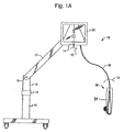
ここで図面について一般的に参照し、図は本発明の好ましい実施形態の説明を目的としたもので本発明を図に限定するものではない。図1Aは、好ましいカート式小型超音波穿刺針誘導システム10を示す。システム10の特徴部の中には、超音波画像処理の際に最適な表示を得るために容易に位置決めできるモニタ20(好ましくはLCDモニタ)、および超音波画像データをコード18経由でモニタ20に送る超音波プローブ30がある。プローブ30は、プローブ30を完全に封入する無菌シェル31に格納されていることが好ましい。プローブ30はプローブ30に回転可能に装着された穿刺針誘導装置を含み、これによって医療従事者は処置中にプローブ30に装着された針に対して角度調整を行うことができる。針に対する角度調整は、針の位置が追跡されて患者内に位置するターゲットと正確に一致するように、超音波画像とともにリアルタイムでモニタ20に表示される。
Reference will now be made generally to the drawings, which are intended to be illustrative of preferred embodiments of the invention and are not intended to limit the invention to the drawings. FIG. 1A shows a preferred cart-type miniature ultrasonic puncture
システム10は軽量であるため比較的容易に移動させることができる。スタンド11はシステム10を支持しており、システムは床を移動するための車輪を含んでいてもよい。スタンド11は、その上端で回転自在アーム17に接続された高さ調整可能なポール13に接続される。締付け環12はポール13を所望高さに固定し、ロック可能な枢軸16はアーム17をポール13に対して所望角度に固定する。このため、システム10を超音波処置に備える際に、モニタ20をユーザのすぐ前方の患者の上方に位置決めできるように移動することができる。これは、高さ調整ポール13を調整し、回転自在アーム17をロック可能な枢軸を中心として枢動することによって完了する。いったん所望の高さに達すると、高さ調整ポール13とアーム17は、締付け環12と枢軸ロック16をそれぞれ締めることによってこの位置でロックされる。システム10は移動し易くかつ軽量であるため、医療従事者は一人で高さと角度の調整を容易に行える。
The
システム10は、超音波画像装置を使った侵襲的医療処置中に「不定な変動」(drift)が発生しないように設計される。医療従事者が注意先を患者身体からモニタに移さなければならないとき(穿刺針の進行を追跡するために)、超音波装置が不整合な状態になるおそれがある。医療従事者はモニタ20上の超音波画像を見ながら患者への速やかな注意と超音波プローブ30の位置/向きを保てるような位置にモニタを選択的に配置して、システム10は不定な変動が生じないようにする。こうして、プローブと患者が超音波画像と同じ視野内にあるようにシステム10を操作することができる。このため、間違いの割合を少なくし、走査および/または針の穿刺の精度を改善し、したがって患者に対する不快感と侵襲的医療処置に要する時間とを少なくすることができる。
The
アーム17を適所に動かしてロックすると、画像がプローブ30に対して正しい向きに現れるようにモニタ20の更なる調整を必要とする場合がある。これは2つの方法の1つで行うことができる。超音波画像は、画面上の画像を回転させて電子的に向きを合せることもできるが、モニタ20がアーム17に対して傾くようにモニタ20をアーム17に枢着することによって位置を変えることもできる。医療従事者は、超音波画像の最適な観察方向が得られるよう画像の調整機能を容易にすることを目的として前述の手法の一方または両方に従うことができる。
If the arm 17 is moved in place and locked, further adjustment of the
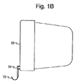
コード18は、スプリングラチェット式または同様の機構を使ってモニタ20に引っ込めることができる。こうして、コード18をモニタ20に出し入れして所望の長さにすることができる。もしくは、無線通信リンクをコード18に代用することもできる。この実施形態では、プローブ30は充電式バッテリなどの携帯型で再生可能な電源をさらに備えていてもよい。図1Bを参照すると、ラッチまたはフック15がモニタ20に装着されており、回転取付け具14を中心として枢動する。プローブ30は、非使用時にフック15に保管して無菌状態に保つことができる。フック15への掛け止め用として、リングなどの他の適当な掛け止め構造をコードのプローブ30の近くに備えてもよい。無線プローブを使用する場合は、適切な掛け止め装置をプローブ30の上端に備えてもよい。モニタ画面の平面内で回転可能な自由旋回軸15に装着されているフック15によって、掛け止めされたプローブ30はモニタ20の向きに関係なくモニタ20から垂直位置に吊される。この構成では、システム10は必要とされていないプローブ30の便利な保管場所を備え、処置の際の移動と術者の誤りを最小にし、さらにプローブを無菌状態に保つ。
The
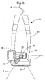
図4と図5は、プローブ30のそれぞれ側面図と正面図を示す。プローブ30は、モニタ20に伝達される画像データを生成する超音波トランスデューサを含む。この画像データは、患者の身体の皮膚線の下のリアルタイム画像を生成するために使用される。処置を行っているときは、プローブ30は図示のように無菌シェル31に格納されていることが好ましい。無菌シェルに格納されることによって、処置中に無菌状態が確保される。無菌スリーブを使用することもできる。代替の実施形態では、無菌スリーブをプローブ30の上端に固定してコード18を封入するように上方に延ばすことができる。このスリーブはシェル31に付属していてもよく、別々に取り付けてもよい。以下にさらに詳しく説明するように、トランスデューサは、シェルの前部と後部、および前端を囲む正面部、すなわち、図5の37で示される領域の間にトランデューサを封入することによって無菌シェル31内に格納すると好都合である。
4 and 5 show a side view and a front view of the
プローブ30は、適宜選定された市販のトランスデューサを備えてもよい。たとえば、プローブ30は、リニアアレイまたは曲面アレイ型として構成されるものでもよく、皮膚表面近くを観察するために高周波帯域(たとえば、10〜15MHz)内を走査するように適合されていてもよく、皮膚表面のかなり下を観察するために低周波帯域(たとえば、5〜7MHz以下)を走査するように適合されていてもよい。超音波画像データは、モニタ20に表示するために適宜選定された超音波システムを使って生成し処理することができる。
The
音響信号は、走査面Bが図4と図5に示されるプローブ30の下の領域を覆うようにトランスデューサの下面37から送受信される。プローブ30の下端には、針誘導部40がある。針誘導部40は針をプローブ30に装着するために使用され、医療従事者は超音波処置中に走査面Bに対して針の角度を連続調整することができる。したがって、システム10では医療従事者が針の角度方向を事前に選択する必要がない。むしろ、皮膚の下の領域の画像が生成される間に正確な角度方向を定めることができる。
The acoustic signal is transmitted and received from the
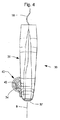
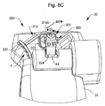
図5Aから分かるように、針誘導部40は、回転可能なシャフト43と、シャフト43から垂直に延びるクリップコネクタ44とを含む。クリップコネクタ44は、針クリップ(たとえば、図8Cに示された針クリップ200)を解放可能に受け入れるようにシェル31に形成された開口35から延びている。この場合、針はつぎに針クリップ200に装着される。針誘導部40に装着された針は、走査面Bに対して連続角度位置にわたって回転することができる。特に、針誘導部40は、針の角度位置が走査面Bに平行な平面にある軸線を中心として測定されるように配置される。したがって、プローブ30は、走査面Bに直角な平面に針を選択的に位置決めするように構成される。
As can be seen from FIG. 5A, the
図5、5A、および8Cを参照すると、シャフト43はシェル31のハウジング34内に受け入れるベアリング43aを含む。このハウジング34によって、シャフト43の回転運動、したがって、走査面Bに平行な平面にある軸線Aを中心とするクリップコネクタ44の回転運動が可能になる(図5および5A)。開口35は、クリップコネクタ44がシェル31から延びて、所定の角度範囲で回転できるようにハウジング34に形成される。他の実施形態では、クリップコネクタ44は、シェル31の開口35から挿入されるように、もしくはシェル31の開口35と同面なるように配置することもできる。クリップコネクタ44はプローブ30に固定され、したがって無菌でないため、この実施形態が好ましい場合もある。クリップコネクタ44を開口35内の凹みに収めることによって、シェル31が汚染される可能性を回避することができる。
Referring to FIGS. 5, 5A, and 8C,
針クリップ200は、クリップコネクタ44を針クリップ200に形成された中空ポスト224内に設置し、クリップコネクタ44に形成された凹部44aによってスナップ係合し、ポスト224の内面に形成された突起を一致させることによってクリップコネクタ44に取り付けられる。クリップ200をクリップコネクタ44に離脱可能に装着するために他の手段を使用することもできる。針クリップ200は、ポスト224の下端の近くに形成された囲いを含んでいてもよい。囲いは、処置中の汚染の可能性をさらに減らすために、針クリップ200をクリップコネクタ44に装着したときにプローブ30を中心とした針クリップの回転を妨げることなく開口35を覆うためのものである。針の軸部は、針クリップ200のクレードル部204に受け入れられ、処置中に締付けアーム216によってクレードル部204に解放可能に保持される。医療従事者が処置を終了した後で針クリップ200をクリップコネクタ44から取り外せるように、ポスト224とクリップコネクタ44のスナップ係合は容易に解放可能であることが好ましい。針クリップ200は使い捨ての針クリップであり、したがって、無菌性を保つために各処置の後で交換可能であることが好ましい。針クリップ200は、プローブ30のトランスデューサが無菌スリーブに包まれるか、もしくは図5に示すような無菌シェル31の第1の実施形態に格納された後、クリップコネクタ44に設置される。
In the
好ましい実施形態では、針誘導部40は針が軸線Aを中心として回転するとき針の角度位置を追跡する穿刺針追跡装置を含む。たとえば、図5Aに示す実施形態では、ポテンショメータ45は回転可能にシャフト43に結合され、軸線Aを中心として回転する針の角変位(または速度)の決定に使用される。シャフト43は、たとえば、シャフト43のねじ端46をポテンショメータ45のロータ部に係合するすることによってポテンショメータ45に結合される。適宜選定された市販の追跡装置をポテンショメータ45に代えて使用し得ることは理解されよう。たとえば、シャフト43は、シャフト43の角運動を検出する位置エンコーダに結合することができる。他の実施形態では、プローブ30に対する針の回転はリビングヒンジを使用して達成することができる。図5Aに示すポテンショメータは、電子信号をプロセッサに伝達するポテンショメータ回路(図示せず)の一部である。これらの信号は、走査面Bに対する針の角度位置のリアルタイムビデオ画像を生成するために使用される。ポテンショメータ回路からの位置データは、トランスデューサにより伝達される信号とは別にモニタ20に伝達することができ、またはこれらを組み合わせて1つの信号とすることもできる。一実施形態では、角度位置データはモニタ20に関連するソフトウェア、もしくはモニタ20に接続された別のコンピュータを使ってトランスデューサからのデータとは別に処理される。このソフトウェアは、超音波画像に重畳された針の向きのリアルタイム連続画像を生成する。他の実施形態では、トランスデューサと角度測定データは、モニタ20に供給される単一のデータストリームを生成するために同時に処理され得る。針の位置情報を処理するために使用されるソフトウェアは、プローブ30に組み入れることができるが、別のコンピュータに常駐させることもできる。
In a preferred embodiment,
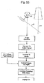
図5Bの略図は、プローブ30に装着された針の動きをモニタ20上のビデオ画像に変換するのに使用できるステップの一実施形態を説明するものである。図に示すように、角度θの針の回転は角度検出器で検出される。この検出器は、この例では、ポテンショメータである。ポテンショメータ45により生成されるアナログ信号は、ディジタル信号に変換される。ポテンショメータ45に代えてディジタル信号エンコーダを使用することもできる。この場合、ディジタル信号は保存されたポテンショメータ較正データに基づいて角度に変換される。この角度データは、さらに保存されたX、Yオフセットパラメータを使って超音波画像に対する深さに変換される。これらのパラメータは、較正データから得られ走査面Bに対する針のオフセット位置を表す。深さ位置はつぎに超音波画像データと組み合わせられてモニタ20に表示される(たとえば、図2と3に示すクロスヘア62a)。
The schematic of FIG. 5B illustrates one embodiment of steps that can be used to convert the movement of a needle attached to the
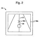
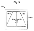
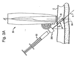
ここで、モニタ20に関連するプローブ30の動作を、図2、2A、3、および3Aを参照して説明する。図2Aと3Aは、クリップコネクタ44に固定された針クリップ200を備えるプローブ30、および針クリップ200に受け入れられた針50の側面図を示す。プローブ30は無菌シェル31に格納されている。針50の先端は、図2Aでは患者の皮膚線Cに接して位置決めされるが皮膚線Cに貫入しておらず、図3Aでは針50の軸部が患者に穿刺されて適切にターゲット64に置かれている。図2Aはトランスデューサの走査面Bに対して第1の角度θ1で配向された針50を示し、図3は走査面Bに対して第2の角度θ2で配向された針50を示す。鎖線DとEはそれぞれ角度θ1、θ2で配向されているときの針50の穿刺経路を表し、図3Aにおける距離δは針50をターゲット64に到達せしめるために穿刺しなければない皮膚線Cから針経路Eに沿った距離である。「針経路」という語は、走査面Bに対して所与の角度で患者の皮膚に穿刺した場合に針50が取ることになる経路を指す。図2Aから分かるように、針経路Dは、角度θ1で配向されているとき意図されたターゲット64の上方で平面Bと交差する。針50がこの角度で穿刺されると、針50はターゲット64を外すことになる。しかし、針50が走査面Bに対して角度θ2で配向されているときは、針50は針経路Eを辿ってターゲット64において走査面Bと交差することになる。
The operation of the
針50を穿刺する前に、正確な針経路と穿刺深さの両方を確認することが望ましい。こうすることによって、患者への不快感(針が皮膚に貫入した後で針位置の調整によって起きる)が最小になり、および/またはターゲットにおける針の位置決め過程が単純になり、これによってターゲット64への針の設置に要する技術レベルと時間が低減される。さらに、針の穿刺深さを知ることが重要である。針の穿刺深さは針の内容物がターゲットに有効に投与される可能性を高めて針の先端が隣接組織に過度の損傷を引き起こさないようにするからである。
Before puncturing the
現状では、医療従事者は針が意図されたターゲットに達しているか否かを判断するとき生体の超音波画像(たとえば、血管壁の歪みなどの組織変形)のみに頼らなければならない場合が多い。たとえば、神経をブロックする局所麻酔を適用するときに針の位置を示す生体の超音波画像に変化がない場合、医療従事者は推量の域を出ない患者の生体構造についての自分の知見に頼らねばならない。医療従事者が針経路、ターゲットの位置、および針の実際の穿刺深さについての正確な情報を得ることができれば、針をより正確にターゲットに設置することができる。 Currently, medical personnel often have to rely only on ultrasound images of the living body (eg, tissue deformations such as vascular wall distortion) when determining whether the needle has reached the intended target. For example, if there is no change in the ultrasound image of the living body showing the needle position when applying local anesthesia to block the nerve, the health care professional relies on his knowledge of the patient's anatomy that is out of the guesswork. I have to. If the health care professional can obtain accurate information about the needle path, target position, and actual puncture depth of the needle, the needle can be more accurately placed on the target.
システム10は、ターゲット64において平面Bに交差するのに必要な針経路とターゲット64に針の先端を設置するのに必要な穿刺深さ(穿刺距離δ)との視覚指標を医療従事者に提供するように構成される。図2と3は、図2Aと3Aに示すプローブ30と針50の位置にそれぞれ対応する、モニタ20に生成される画像60aと60bをそれぞれ示す。クロスヘア62aと62bは、それぞれの針経路DおよびEと走査面Bとの間の交差部分の点を示す。また、血管壁の断面を、ターゲット64に対応する血管壁の断面とともに図2と3に示す。画像64aは、針経路Dがターゲット64の上方で平面Bと交差することになることを示し(クロスヘア62a)、これは針経路Dが浅すぎることを意味する。画像60bは、針経路がターゲット64において平面Bと交差することを示し(クロスヘア62bはターゲット64を覆っている)、これは針経路Eが針50の正確な穿刺経路であることを意味する。
The
針50の穿刺距離δは、穿刺角度θ2と、前述のX、Y位置パラメータとともに保存され得る他の既知の距離から得ることができる。たとえば、穿刺深さはθ2、表面37とターゲット64からの距離、針軸部中心線(針クリップにおける)と走査面Bの水平距離、および針軸部中心線(針クリップにおける)とプローブ30の底面の垂直距離から決定することができる。いったん得られた針の穿刺深さは、所望の深さを超えて針50の穿刺されることを阻止するスコアラインを針50またはストッパ部材に設けることによって距離δに合わせることができる。いくつかの処置については、医療従事者は正確な設置のためにδを知る必要がない場合もある。たとえば、針50を血管壁に使用しようとする場合、視覚的に確認される血管壁の歪み、針の軸部路を通る血液の流れ、または針50の貫入に対する抵抗の変化が正確な設置を確認するのに十分な場合がある。神経をブロックするために局所麻酔を適用するときなどの他の応用では、δを知ることがターゲットを決定するのに有用な場合もあり、すなわち、医療従事者はこの場合も超音波画像における組織変化に頼ることができる。超音波画面では、針の位置の間接的な、すなわち二次的な徴候として針がその組織を通過していることを示す軟組織変形を含み、超音波ビームが針に当ると低エコー音響陰影および多重反射(ring down artifact)を含む場合がある。これらの二次的な徴候のすべては、針そのものが可視化されないときに重要である。クロスヘア(または適切に選定された他の指標)は、これらの二次的な徴候の発現を観察するためのフォーカスポイントを提供し得る。針経路はモニタ20に示されるため、医療従事者はクロスヘアに注意を集中することができる。第一に針そのものを可視化するか、もしくは前述の二次的指標の1つによって針がいったんターゲットに置かれると、ごく少量の局所麻酔剤を注射することができ、これが反射超音波によって検出可能になり表示されたクロスヘアに超音波画像の変化が現れる可能性がある。同様に、直接可視化または二次的徴候によって穿刺針の先端がターゲットに置かれると、超音波誘導システムは針を解放することができ、さらに、ターゲットに対する先端を含む針の全長を明視化するために針が穿刺された状態と平行にトランスデューサの向きを合せることができる。
The puncture distance δ of the
図2、3、2A、および3Aを参照すると、意図されたターゲット64に対する針50の正確な位置決めは以下のように進行する。まず、処置中の不定な変動の発生を回避するために、モニタ20は患者と超音波装置の、医療従事者の直近の視野内に定置される。最初、モニタ20がターゲットの上方にクロスヘア(たとえば、クロスヘア62a)を表示する場合は、針経路は調整を必要とする。この調整は、図3Aにおいて針50の穿刺角度を時計回りに回転させて行われる(当然、クロスヘア62aがターゲット64の下にある場合は、図3Aで針50は反時計回りに回転されることになる)。この回転運動は、ポテンショメータ回路の抵抗の変化によって検出される。処理された信号は、下方に移動するクロスヘアとしてモニタ20に表示される針経路に関するリアルタイム角度位置情報を生成する。針50を回転させて針経路を下方に調整すると、クロスヘア62aはクロスヘア62bに対応したターゲット64に達するまで下方にターゲット64に向かって移動する。いったんクロスヘアがターゲットの中心に置かれると、所望の針経路が決定される。針経路が見付かった後、クリップは針誘導部40のシャフト43の設定された回転抵抗によって対応する位置に留まること望ましい。好ましくは、回転抵抗は摩擦によってシャフト43に与えられ、緩衝装置がシャフト43に結合される。もしくは、ポテンショメータアセンブリによってシャフト43に回転抵抗を与えてもよい。回転抵抗はユーザの援助なしで針を定位置に保持するため、針経路を確実に維持することができる。針経路Eが見付かった後、針50をターゲット64のある位置までの距離δ(θ2)だけ穿刺することができる。いったんターゲット64に達すると、プローブ30を針50から外すことができる。プローブ30を針50から取り外した後、前述したように、プローブ30はモニタ20に取り付けられたプローブ取付けフック15に掛けておくことができる。あるいは、無菌シェル31と超音波コード18の長さを下方に延びる任意の無菌スリーブとによって、プローブ30を無菌野に置くこともできる。こうすることによって、プローブ30が再び必要になった場合にプローブとコードの無菌性が保たれており、処置の残る部分を通常の無菌状態で行うことができる。
With reference to FIGS. 2, 3, 2A, and 3A, accurate positioning of the
プローブ30のアセンブリは針誘導部40の較正を含む。つまり、針の角度の変化に対するポテンショメータ回路の変化の較正と、超音波画像の深さ位置による角度データの較正(たとえば、モニタ20に表示される画像面に対するクロススヘアの位置)である。ポテンショメータ(または位置エンコーダ)は任意の公知の方法で較正され得ることは理解されよう。角度データがポテンショメータ回路の変化に対して較正された後、針の増分角度回転が周知の補間アルゴリズムを使ってポテンショメータ回路の増分変化から決定され得る。この後、深さ位置データ(たとえば、図5BのX、Yオフセットパラメータ)が計算される。これらの深さ位置データは、ポテンショメータに対する針経路のオフセット位置とトランスデューサに対するポテンショメータの位置を含む。この後、これらのパラメータは、計算された角度変化とともに深さ位置の計算、すなわち、画像面における針経路の交差を計算するために使用される。
The assembly of
前述のように、針誘導部40は、針の角度位置が走査面Bに平行な平面内にある軸線を中心として測定されるように配置される。したがって、プローブ30は走査面Bに直角な平面に針を選択的に位置決めするように構成される。他の実施形態では、針の角度位置は、誘導部に受け入れられた針が貫入する体表面に垂直な平面内にある軸線を中心として測定されるが、走査面に平行な平面にある軸線を中心とした測定は行われない。たとえば、角度位置は、走査面と、少なくとも10、15、30、45、60、75、45〜 90°、または最大90°の角度をなす平面内にある回転軸線に対して測定され得る。これらの実施形態では、針誘導部は針誘導部40と同様に構成され得るが、トランスデューサへの取付けは、針が貫入する体表面に垂直な平面内で針が回転し、走査面に平行な平面内では針が回転しないように針の回転軸線が配向される。このような実施形態は、ターゲットに対する針位置の追跡および針とターゲットの心合せなど、以前に開示された実施形態の様々な利点も提供することができる。
As described above, the
前述のように、プローブ30は無菌の使い捨てシェル31に格納されることが好ましい。シェル31は針誘導部40を受け入れるハウジング34とともに構成され、針誘導部40はトランスデューサの外側部分に取り付けられてトランスデューサ全体を格納する。シェル31をトランスデューサと針誘導部40に取り付けるとき、前と後ろのシェル部分を使用して前と後ろのシェル部分を一緒にしスナップファスナーなどで保持することができる。
As described above, the
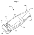
無菌シェルの第2の実施形態を図6と7に示す。シェル100は、第1の実施形態のシェル31と同様に、プローブ全体を覆うように形成されたクラムシェルである。ただし、シェル100は、針誘導部がトランスデューサ本体の中に組み入れられる超音波プローブの実施形態を網羅するように形成される。したがって、この実施形態では、針誘導部40を受け入れるように形成されたハウジング部を備える必要性がない。これらの部品はトランスデューサ本体に備えられているからである。シェル31と100は、容易に密封可能で、従来のスリーブよりも裂け目を生じにくく、無菌コードを必要とする処置に対して任意のスリーブを有する比較的硬質のプラスチック製であり、射出成形によって形成されることが好ましい。
A second embodiment of a sterile shell is shown in FIGS. Similar to the
図6を参照すると、シェル100は上部104、下部102、およびプローブ30を格納する前部106を含む。前端106の前面107は、大きな減衰なしで音波を通過させることができる。部分102と104で形成される後端110は、モニタ20にプローブ30を接続するコード用の開口を備える。隆起領域108は、前述のように、プローブに装着された針の角度方向を調整するためにクリップコネクタ44を所定の角度範囲内で自由に動かせるサイズに作られた長孔108aを含む。他の実施形態では、クリップコネクタ44は、無菌性を保つために孔108a内に引っ込めるか、もしくは孔108aと同面となるように配置され得る。さらに、針クリップ200(クリップコネクタ44で受入れ可能)は、前述のように、針クリップ200の回転を妨げることなく無菌性を保つことを目的として孔108aを覆うためにポスト224の端部の近くに囲いを備えていてもよい。
Referring to FIG. 6, the
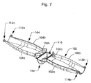
上部と下部102、104を一体とするために、1対のスナップコネクタ112、114、または他の適当なファスナーが使用される。図7はプローブを封入する前のシェル100を示す。シェル100は1部品構成である。前部106は、リビングヒンジ106aと106bによって上部104と下部102に接続される。シェル100は、前端106を音響結合ゲルの容器として使用できるように設計される。したがって、シェル100は、容器領域116に音響ゲルが備えられ、取外し可能なリッドストックで密封され得る。
A pair of
プローブは、以下のようにシェル100内に格納することができる。まず、音響ゲルを密封しているリッドストックを剥がす。これによって、音響ゲルが露出してプローブの送信端を空間116に挿入することができる。つぎに、縁部102b、102a、104a、および104bが整合して無菌障壁を形成するまで、リビングヒンジ106a、106bを中心に回転させて部分102と104を一体とする。良好な無菌障壁とし易くするために、縁部102b、102a、104a、および104bに協働ラップジョイントを形成する。この後、スナップコネクタ112、114のオス部分112a、114aとメス部分112b、114bは、スナップ係合によって結合される。プローブをシェル100から取り出す時点でオス部分112a、114aを下に押してスナップコネクタ112、114を分離することができるように、オス部分112a、114aに突起が形成される。
The probe can be stored in the
前述するとともに以下にさらに詳しく説明するように、針をプローブ30などのプローブに固定するために使い捨ての針クリップが使用され、プローブ30がシェル100に封入された後、この針クリップはクリップコネクタ44でプローブ30に取り付けられる。針クリップ200は、シェル31および100と同様に、無菌であり、使用時まで無菌状態で保管される。したがって、シェルをプローブにスナップ係合すると汚染の可能性が最小限に抑えられる。無菌性を維持する問題には、2つの特徴によって対応される。第1に、クリップコネクタ44を、完全に閉じられたシェル31および100の開口35または108aを超えて広がらないように配置することができる。これで、非無菌クリップコネクタによるシェル開口の汚染が回避される。第2に、針クリップ200に、孔35または108aの開口を覆っていてこれには接触しない囲いを設けることができる。これで、無菌シェルの汚染の可能性を回避する第2の障壁と入り組んだ経路が備えられる。理想的には、針クリップと無菌シェルは、各々が無菌ゲルパケット、シェル、少なくとも1つの針クリップ、および任意のコード用無菌スリーブを収容する、組立式無菌キットととして入手される。したがって、超音波プローブとコードの周りの外面が無菌で提供される一方で、針クリップとクリップコネクタは回転してポテンショメータアセンブリによる監視が可能である。
As described above and in more detail below, a disposable needle clip is used to secure the needle to a probe, such as
ここで、プローブ30を参照して針クリップをさらに詳しく説明することにする。針クリップは、医療従事者が処置中に針クリップを容易に係合および離脱し、針をプローブ30に対してそれぞれ固定および解放できるように設計されることが好ましい。特に、針クリップは、針50が患者内に埋め込まれている間に針軸部の動きが最小になるようにして、プローブ30を針50から外せるように設計することが望ましい。ここで、図8〜10を参照して針クリップの第1、第2、第3、および第4の実施形態を説明することにする。
Here, the needle clip will be described in more detail with reference to the
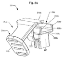
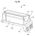
図8A、8B、および8Cを参照すると、針クリップ200の第1の実施形態は、第1の部品201(図8A)と第2の部品202(図8B)を含む。他の実施形態では、部品201と202は2部品構成と対照的な一体型であってもよい。針の軸部を受け入れる半円形のクレードル204が第2の部品の表面に形成される。第2の部品202は、第1の部品200の保持部226内に摺動係合するような大きさに作られる。保持部226に挿入すると、隆起212a、212bは保持部226の側壁226a、226bに形成された溝228a、228bとそれぞれ係合する。第2の部品202の壁部208は、第2の部品202が保持部226に完全に受け入れられたときに保持部226の表面226cに当接する面210を有する。壁面210と表面226cのこの接触によって、第2の部品202が保持部226内に留まるようになる。第1の部品201と第2の部品202を確実に結合するために、第2の部品202の一端に柔軟なフィンガーを形成してもよい。組立済みの針クリップ200は、第1の部品201に形成された中空ポスト224をクリップコネクタ44の上に設置することによってクリップコネクタ44に固定される。図8Cは、プローブ30のクリップコネクタ44に固定された組立済みの針クリップ200を示す。
With reference to FIGS. 8A, 8B, and 8C, a first embodiment of the
図8Aと8Cを参照すると、第1の部品201は撓み部材222によってポスト224に固定された締付けアーム216を含む。締付けアーム216の第1の端部216aには指掛け220が設けられ、反対端にはカバー216bが保持部226に隣接して配置される。撓み部材222は、指掛け220に加えられた指圧によって保持部224の方向に容易に曲げられ得る湾曲状をなす。クリップコネクタ200は、指掛け220に一定の指圧を加えることによってクレードル204に針を保持する。指圧(図8Cに力Fで示されている)を指掛け220に加えると、撓み部材222は保持部226の方向に曲って、カバー216bがクレードル204の上を覆い(図8Cのd1の方向)、これによって針軸部がカバー216bとクレードル204の間に捕捉される。針をプローブ30から分離するときは、ユーザは指掛け220に加えた指圧を取り除くだけで撓み部材22はその変形前の位置に戻り(図8C)、カバー216bは当初の位置に戻ることができる。この作用によって、余分な動きなしで、他の医療従事者の助けを借りることなく、機械的接続を切らずに、したがって患者に埋め込まれた状態にある針軸部をほとんど、もしくは全く乱すことなく針軸部をプローブ30から分離することができる。
With reference to FIGS. 8A and 8C, the
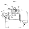
ここで、図9と10を参照して針クリップの第2および第3の実施形態を説明することにする。第2の実施形態では、針クリップには第1の部品と第2の部品があり、これらは針クリップ200と同様の形式でクリップコネクタ44に固定することができる。第3の実施形態では、針クリップには3個の部品がある。これら他の実施形態では、針部品200に関して前述した、保持部、ポスト、および第2の部品に関連した同じ構造が使用される(あるいは、これらの実施形態では、1部品構成および2部品構成をそれぞれ2部品構成および3部品構成に選定することができる)。ただし、これら他の実施形態は、締付けアームに関連する駆動の構造と方法が異なる。したがって、針クリップに関連するその他の構造体の構造と機能は第1の実施形態の説明にかんがみて容易に理解されるという理解の下で第2と第3の実施形態の説明を進めることにする。
A second and third embodiment of the needle clip will now be described with reference to FIGS. In the second embodiment, the needle clip has a first part and a second part, which can be secured to the
ここでは、図9を参照して針クリップ400の第2の実施形態を説明することにする。この実施形態では、締付けアーム416(その正面と裏面でポスト226に装着された)は、カバー416bがクレードル204に隣接し、その反対側に配置されるように保持部426の周りに延びる湾曲部分417を有する。第1の実施形態におけるように、指圧を加えたときカバー416bはクレードル204の上を覆う。カバー416bの駆動は、指掛け420を下方に押すことによって達成され、これによって、針軸部がクレードル204とカバー416bの間に捕捉されるようにカバー416bはクレードル204の上に移動する(方向d3)。カバー416bが移動して開始位置に戻るように指圧を解放すると、針をクレードル204から外すことができる(図9)。
Here, a second embodiment of the
ここで、図10を参照して針クリップ500の第3の実施形態を説明することにする。この実施形態では、締付けアーム516は、クレードル204に隣接して配置される第1の部品201の溝形部分522に摺動式に受け入れられる。撓み部材524は下面516aにおいて締付けアーム516に装着されてプローブ30の面524aに当接するように適合され、これによって、指掛け520に指圧が加えられたときに撓み部材524は指掛け520の方向に撓む。指圧が加えられる前には、カバー516bはクレードル204を覆っていない。指圧が加えられると、カバー516bはクレードル204の上を覆い、これによって針軸部がクレードル204とカバー516bの間に捕捉される。指圧が加えられている間、撓み部材524は撓んだ状態に保たれる。指圧が取り除かれると、撓み部材524が変形されていない状態に戻るにつれて、撓み部材524はカバー516bを元の(すなわち、クレードル204を覆わない)位置に戻すことになる。この後、針軸部をプローブ30から分離することができる。この実施形態では、前述の他の実施形態と同様に、機械的接続を切らずに、したがって患者に埋め込まれた状態にある針軸部をほとんど乱すことなく針軸部をプローブ30から分離するために使用することができる。
A third embodiment of the
当業者は前述の説明を読むといくつかの変形例と改良を思いつくであろう。たとえば、無菌シェルは、既存の超音波プローブとともに使用できるように製作して従来のプローブスリーブよりも便利で実用的な無菌カバーを提供することができる。また、カート式小型超音波システムは、他のタイプの入手できるプローブとともに使用できるように変更して、より完成度が高く使い易い携帯型の超音波システムを提供することができる。さらに、本発明は、リアルタイム二次元超音波を使った前述の実施形態に加えて、三次元および四次元(リアルタイム三次元)超音波に対応するように構成することができる。本明細書では簡潔さと読み易さに配慮してすべての変形例と改良を割愛しているが、これらは当然本発明の範囲内にある。 Those skilled in the art will be able to come up with several variations and improvements upon reading the foregoing description. For example, a sterile shell can be fabricated for use with existing ultrasound probes to provide a more convenient and practical sterile cover than conventional probe sleeves. Also, the cart-type miniature ultrasound system can be modified for use with other types of available probes to provide a portable ultrasound system that is more complete and easy to use. Furthermore, the present invention can be configured to support three-dimensional and four-dimensional (real-time three-dimensional) ultrasound in addition to the above-described embodiments using real-time two-dimensional ultrasound. In the present specification, all modifications and improvements are omitted for the sake of brevity and readability, but these are naturally within the scope of the present invention.
Claims (49)
前記トランスデューサに結合されている針ガイドと
を備え、
前記針ガイドが、該針ガイドに受け入れられる針が穿刺される体表面に垂直な平面内で回転可能であり、
前記平面が前記走査面に非平行となっている、超音波プローブ。 A transducer configured to generate an ultrasound image of the scan plane;
A needle guide coupled to the transducer;
The needle guide is rotatable in a plane perpendicular to the body surface into which the needle received in the needle guide is punctured;
An ultrasonic probe, wherein the plane is non-parallel to the scanning plane.
前記トランスデューサに装着され、前記走査面に平行な平面内にある軸線を中心として回転するように構成された部材と、
前記部材に結合される位置検出器と、
針ホルダを受け入れるように構成され、前記部材に接続され、前記針ホルダに受け入れられる針が前記部材の軸線を中心として回転され得るように前記トランスデューサから外方に延びるアームと
を備える、超音波プローブ。 A transducer configured to generate an ultrasound image of the scan plane;
A member mounted on the transducer and configured to rotate about an axis in a plane parallel to the scan plane;
A position detector coupled to the member;
An ultrasound probe configured to receive a needle holder, connected to the member and extending outwardly from the transducer so that a needle received in the needle holder can be rotated about an axis of the member .
走査面を有する携帯型超音波プローブと、
前記走査面に平行な平面内にある軸線を中心として回転する前記携帯型超音波プローブに結合された針ホルダを含む針誘導部であり、前記針ホルダが前記針ホルダから始まり前記走査面の中を通って延びる針経路を画成する、前記針誘導部と、
前記針誘導部によって生成される針経路のデータを使って前記針経路と前記走査面の交差部分を決定する回路と
を備える装置。 A device for tracking the position of a needle relative to an ultrasound image,
A portable ultrasound probe having a scanning surface;
A needle guide including a needle holder coupled to the portable ultrasonic probe that rotates about an axis in a plane parallel to the scanning plane, the needle holder starting from the needle holder, The needle guide defining a needle path extending therethrough;
An apparatus comprising: a circuit for determining a crossing portion of the needle path and the scanning plane using data of the needle path generated by the needle guiding unit.
前記走査面に対する角度位置を有する前記針を前記携帯型超音波プローブに装着するステップと、
患者に前記携帯型超音波プローブを配置するステップと、
前記ターゲット組織を含む前記走査面の二次元画像であり、前記ターゲット組織に対して予想される針位置の視覚指標を含む前記二次元画像を表示するステップと、
前記視覚指標の対応する動きを監視しながら前記走査面に平行な平面内にある軸線を中心として前記針を回転するステップと、
前記視覚指標が前記ターゲット組織と一致したとき前記ターゲット組織に前記針を設置するステップと
を備える方法。 A method of positioning a needle for target tissue treatment within a patient using a portable ultrasound probe having a scan plane, comprising:
Attaching the needle having an angular position to the scanning plane to the portable ultrasonic probe;
Placing the portable ultrasound probe on a patient;
Displaying a two-dimensional image of the scan plane containing the target tissue, including a visual indicator of the expected needle position relative to the target tissue;
Rotating the needle about an axis in a plane parallel to the scan plane while monitoring the corresponding movement of the visual indicator;
Placing the needle on the target tissue when the visual indicator matches the target tissue.
前記穿刺深さ情報による深さまで前記針を穿刺するステップと
をさらに含む、請求項20に記載の方法。 Obtaining puncture depth information for determining the puncture depth of the needle to the patient;
21. The method of claim 20, further comprising puncturing the needle to a depth according to the puncture depth information.
走査面を有する携帯型超音波プローブを用意するステップと、
前記針から前記走査面に延びる針経路を有する前記針を前記携帯型超音波プローブの針ガイドに装着するステップと、
前記針ガイドを前記走査面に直角な平面内で回転するステップと、
前記針ガイドの回転に応じて前記針経路と前記走査面の交差部分を決定するステップと
を備える方法。 A method of tracking the position of a needle relative to a target tissue,
Providing a portable ultrasound probe having a scanning surface;
Attaching the needle having a needle path extending from the needle to the scanning surface to a needle guide of the portable ultrasonic probe;
Rotating the needle guide in a plane perpendicular to the scanning plane;
Determining the intersection of the needle path and the scan plane in response to rotation of the needle guide.
走査面を有する超音波プローブと
前記超音波プローブによって生成される前記走査面の超音波画像を表示するディスプレイと、
前記走査面に平行な平面内にある軸線を中心として前記超音波プローブに対して回転運動する、前記超音波プローブに結合される針ガイドと、
前記針ガイドに結合される位置検出器と、
前記位置検出器からデータを生成する回路と
を備え、
前記ディスプレイが、前記回路データに基づいて前記超音波画像とともに表示される予想針位置の視覚指標をさらに含む、システム。 A system for determining a puncture point,
An ultrasonic probe having a scanning plane; and a display for displaying an ultrasonic image of the scanning plane generated by the ultrasonic probe;
A needle guide coupled to the ultrasound probe that rotates relative to the ultrasound probe about an axis in a plane parallel to the scan plane;
A position detector coupled to the needle guide;
A circuit for generating data from the position detector,
The system, wherein the display further includes a visual indicator of expected needle position that is displayed with the ultrasound image based on the circuit data.
前記針クリップが、
針用のクレードルと、
カバーを形成する端部を有するアームと
を備え、
前記カバーが、前記クレードルを開く第1の位置と前記クレードルを閉じる第2の位置との間で手動による移動が可能であり、
前記カバーが、前記第2の位置で前記クレードルから分離され、前記針クリップに外圧が加えられてときのみ前記カバーが前記第2の位置に保持可能となるように構成され、
前記カバーが、前記第2の位置にあるとき、第1の方向への針の移動を許容し、前記第1の方向に垂直な第2の方向への針の移動を実質的に阻止するように、前記カバーと前記クレードルがともに前記カバーと前記クレードルとの間に使い捨ての針軸部のための通路を形成する、超音波プローブ。 An ultrasonic probe comprising a needle clip coupled to a transducer, comprising:
The needle clip is
A cradle for the needle,
An arm having an end forming a cover,
The cover is manually movable between a first position for opening the cradle and a second position for closing the cradle;
The cover is separated from the cradle in the second position, and is configured such that the cover can be held in the second position only when an external pressure is applied to the needle clip;
When the cover is in the second position, it allows the needle to move in a first direction and substantially prevents the needle from moving in a second direction perpendicular to the first direction. An ultrasonic probe in which the cover and the cradle together form a passage for a disposable needle shaft between the cover and the cradle.
前記アームへの前記圧力が除去されると、前記カバーが前記第1の端部に蓄えられた弾性エネルギーのみによって前記第1の位置に戻る、請求項35に記載の超音波プローブ。 The first end is not deformed when the cover is in the first position, and the first end is deformed by the pressure applied to the arm when the cover is in the second position. ,
36. The ultrasound probe of claim 35, wherein when the pressure on the arm is removed, the cover returns to the first position only by elastic energy stored at the first end.
針の軸部を受け入れるようになっている移動可能なカバーとクレードルを含む針クリップを前記超音波プローブに設ける第1ステップと、
前記針軸部を前記クレードルに設置する第2ステップと、
前記カバーが前記クレードルの先端の第1の位置から前記クレードルの末端の第2の位置に移動するように前記カバーに圧力を加えて前記針を前記クレードルと前記カバーの間に保持する第3ステップと、
前記カバーの前記圧力を除去して前記カバーを前記第2の位置から前記第1の位置に移動する第4ステップと
を含む方法。 A method of releasably fastening a needle to an ultrasonic probe,
Providing the ultrasonic probe with a needle clip including a movable cover adapted to receive a needle shaft and a cradle;
A second step of installing the needle shaft portion in the cradle;
A third step of applying pressure to the cover to hold the needle between the cradle and the cover such that the cover moves from a first position at the tip of the cradle to a second position at the end of the cradle; When,
And a fourth step of removing the pressure of the cover and moving the cover from the second position to the first position.
前記圧力を除去する前記第4ステップが、前記カバーが前記変形した部材に蓄えられた前記弾性エネルギーのみによって前記第1の位置に戻るように前記部材を変形前の状態に復元する工程を含む、請求項42に記載の方法。 The third step of applying the pressure includes the step of deforming a member connected to the cover at a first end of the cover;
The fourth step of removing the pressure includes a step of restoring the member to a state before the deformation so that the cover returns to the first position only by the elastic energy stored in the deformed member. 43. The method of claim 42.
第1のシェル部分と、
第2のシェル部分と、
前記超音波プローブの端部を受け入れる容器を画成する第3のシェル部分と、
前記第1のシェル部分と前記第3のシェル部分を接続する第1のリビングヒンジと、
前記第2のシェル部分と前記第3のシェル部分を接続する第2のリビングヒンジと
を備える、無菌シェル。 A sterile shell for an ultrasonic probe,
A first shell portion;
A second shell portion;
A third shell portion defining a container for receiving an end of the ultrasonic probe;
A first living hinge connecting the first shell portion and the third shell portion;
A sterile shell comprising: the second shell portion and a second living hinge connecting the third shell portion.
第1のシェル部分、第2のシェル部分および第3のシェル部分を包含する無菌シェルを設けるステップと、
カバーを前記第3のシェル部分から取り外すステップと、
前記プローブの導波路を前記第3のシェル部分の内部に設置するステップと、
前記第2のシェル部分と前記第1のシェル部分上にプローブを配置し、それによって前記プローブを前記シェル内に封入するステップと
を含み、
第1のリビングヒンジが前記第1のシェル部分と前記第3のシェル部分を接続し、第2のリビングヒンジが前記第2のシェル部分と前記第3のシェル部分を接続し、前記第3のシェル部分がゲルを含有している、方法。 A method of storing an ultrasonic probe in a sterile shell, comprising:
Providing a sterile shell including a first shell portion, a second shell portion and a third shell portion;
Removing the cover from the third shell portion;
Placing the waveguide of the probe inside the third shell portion;
Disposing a probe on the second shell portion and the first shell portion, thereby encapsulating the probe in the shell;
A first living hinge connects the first shell portion and the third shell portion, a second living hinge connects the second shell portion and the third shell portion, and the third living hinge The method wherein the shell portion contains a gel.
Applications Claiming Priority (4)
| Application Number | Priority Date | Filing Date | Title |
|---|---|---|---|
| US71419205P | 2005-09-02 | 2005-09-02 | |
| US80855206P | 2006-05-26 | 2006-05-26 | |
| US11/508,300 US8852111B2 (en) | 2005-09-02 | 2006-08-23 | Ultrasound guidance system |
| PCT/US2006/033145 WO2007027511A2 (en) | 2005-09-02 | 2006-08-24 | Ultrasound guidance system |
Publications (2)
| Publication Number | Publication Date |
|---|---|
| JP2009506830A true JP2009506830A (en) | 2009-02-19 |
| JP2009506830A5 JP2009506830A5 (en) | 2009-10-08 |
Family
ID=37809380
Family Applications (1)
| Application Number | Title | Priority Date | Filing Date |
|---|---|---|---|
| JP2008529122A Pending JP2009506830A (en) | 2005-09-02 | 2006-08-24 | Ultrasonic guidance system |
Country Status (5)
| Country | Link |
|---|---|
| US (3) | US8852111B2 (en) |
| EP (1) | EP1931261A4 (en) |
| JP (1) | JP2009506830A (en) |
| CA (1) | CA2662254A1 (en) |
| WO (1) | WO2007027511A2 (en) |
Cited By (6)
| Publication number | Priority date | Publication date | Assignee | Title |
|---|---|---|---|---|
| JP2013507177A (en) * | 2009-10-09 | 2013-03-04 | ソーマ・アクセス・システムズ・エルエルシー | Clamp for medical probe device |
| JP2013516288A (en) * | 2010-01-07 | 2013-05-13 | ベラソン インコーポレイテッド | Vascular access device, system and method |
| JP2016036501A (en) * | 2014-08-07 | 2016-03-22 | 株式会社東芝 | Puncture adapter, ultrasonic probe, and ultrasonic diagnostic equipment |
| JP2016093505A (en) * | 2014-11-12 | 2016-05-26 | シブコ メディカル インストルメンツ カンパニー インコーポレイテッドCivco Medical Instruments Co.,Inc. | Needle guide devices for mounting on imaging transducers or adaptors on imaging transducer, imaging transducers for mounting needle guide devices and adaptors for imaging transducers for mounting needle guide devices thereon |
| JP2019528926A (en) * | 2016-10-11 | 2019-10-17 | アヴェント インコーポレイテッド | System and method for enhancing echogenicity of nerve fibers using targeted metal particles |
| JP2019188005A (en) * | 2018-04-27 | 2019-10-31 | キヤノンメディカルシステムズ株式会社 | Ultrasonic diagnostic apparatus and paracentesis support program |
Families Citing this family (121)
| Publication number | Priority date | Publication date | Assignee | Title |
|---|---|---|---|---|
| US7850610B2 (en) * | 2004-06-28 | 2010-12-14 | Medtronic, Inc. | Electrode location mapping system and method |
| US8784336B2 (en) | 2005-08-24 | 2014-07-22 | C. R. Bard, Inc. | Stylet apparatuses and methods of manufacture |
| WO2008017051A2 (en) | 2006-08-02 | 2008-02-07 | Inneroptic Technology Inc. | System and method of providing real-time dynamic imagery of a medical procedure site using multiple modalities |
| US8388546B2 (en) | 2006-10-23 | 2013-03-05 | Bard Access Systems, Inc. | Method of locating the tip of a central venous catheter |
| US7794407B2 (en) | 2006-10-23 | 2010-09-14 | Bard Access Systems, Inc. | Method of locating the tip of a central venous catheter |
| US20090093719A1 (en) * | 2007-10-03 | 2009-04-09 | Laurent Pelissier | Handheld ultrasound imaging systems |
| US9521961B2 (en) | 2007-11-26 | 2016-12-20 | C. R. Bard, Inc. | Systems and methods for guiding a medical instrument |
| US9649048B2 (en) | 2007-11-26 | 2017-05-16 | C. R. Bard, Inc. | Systems and methods for breaching a sterile field for intravascular placement of a catheter |
| US10751509B2 (en) | 2007-11-26 | 2020-08-25 | C. R. Bard, Inc. | Iconic representations for guidance of an indwelling medical device |
| US8781555B2 (en) | 2007-11-26 | 2014-07-15 | C. R. Bard, Inc. | System for placement of a catheter including a signal-generating stylet |
| US10449330B2 (en) | 2007-11-26 | 2019-10-22 | C. R. Bard, Inc. | Magnetic element-equipped needle assemblies |
| US9636031B2 (en) | 2007-11-26 | 2017-05-02 | C.R. Bard, Inc. | Stylets for use with apparatus for intravascular placement of a catheter |
| US10524691B2 (en) | 2007-11-26 | 2020-01-07 | C. R. Bard, Inc. | Needle assembly including an aligned magnetic element |
| ES2651898T3 (en) | 2007-11-26 | 2018-01-30 | C.R. Bard Inc. | Integrated system for intravascular catheter placement |
| US8849382B2 (en) | 2007-11-26 | 2014-09-30 | C. R. Bard, Inc. | Apparatus and display methods relating to intravascular placement of a catheter |
| US8073529B2 (en) * | 2007-12-04 | 2011-12-06 | Civco Medical Instruments Co., Inc. | Needle guide system for use with ultrasound transducers to effect shallow path needle entry and method of use |
| WO2009094646A2 (en) | 2008-01-24 | 2009-07-30 | The University Of North Carolina At Chapel Hill | Methods, systems, and computer readable media for image guided ablation |
| US8478382B2 (en) | 2008-02-11 | 2013-07-02 | C. R. Bard, Inc. | Systems and methods for positioning a catheter |
| US20090221908A1 (en) * | 2008-03-01 | 2009-09-03 | Neil David Glossop | System and Method for Alignment of Instrumentation in Image-Guided Intervention |
| US8340379B2 (en) * | 2008-03-07 | 2012-12-25 | Inneroptic Technology, Inc. | Systems and methods for displaying guidance data based on updated deformable imaging data |
| US9022940B2 (en) * | 2008-07-18 | 2015-05-05 | Joseph H. Meier | Handheld imaging devices and related methods |
| JP2011530366A (en) * | 2008-08-12 | 2011-12-22 | コーニンクレッカ フィリップス エレクトロニクス エヌ ヴィ | Ultrasound imaging |
| ES2525525T3 (en) | 2008-08-22 | 2014-12-26 | C.R. Bard, Inc. | Catheter assembly that includes ECG and magnetic sensor assemblies |
| US8170257B2 (en) * | 2008-08-29 | 2012-05-01 | Wayne G P Chan | Apparatus for reducing background and wind noise to a microphone |
| US8437833B2 (en) | 2008-10-07 | 2013-05-07 | Bard Access Systems, Inc. | Percutaneous magnetic gastrostomy |
| WO2010080637A1 (en) | 2008-12-18 | 2010-07-15 | C. R. Bard, Inc. | Needle guides for a sonographic imaging device |
| US10863970B2 (en) | 2008-12-18 | 2020-12-15 | C. R. Bard, Inc. | Needle guide including enhanced visibility entrance |
| US8641621B2 (en) * | 2009-02-17 | 2014-02-04 | Inneroptic Technology, Inc. | Systems, methods, apparatuses, and computer-readable media for image management in image-guided medical procedures |
| US8690776B2 (en) | 2009-02-17 | 2014-04-08 | Inneroptic Technology, Inc. | Systems, methods, apparatuses, and computer-readable media for image guided surgery |
| US8554307B2 (en) | 2010-04-12 | 2013-10-08 | Inneroptic Technology, Inc. | Image annotation in image-guided medical procedures |
| US11464578B2 (en) | 2009-02-17 | 2022-10-11 | Inneroptic Technology, Inc. | Systems, methods, apparatuses, and computer-readable media for image management in image-guided medical procedures |
| JP5671008B2 (en) | 2009-04-28 | 2015-02-18 | コーニンクレッカ フィリップス エヌ ヴェ | Biopsy guide system with ultrasonic transducer and method of use thereof |
| US10039527B2 (en) | 2009-05-20 | 2018-08-07 | Analogic Canada Corporation | Ultrasound systems incorporating spatial position sensors and associated methods |
| US8556815B2 (en) | 2009-05-20 | 2013-10-15 | Laurent Pelissier | Freehand ultrasound imaging systems and methods for guiding fine elongate instruments |
| US20100312121A1 (en) * | 2009-06-09 | 2010-12-09 | Zhonghui Guan | Apparatus for a needle director for an ultrasound transducer probe |
| ES2745861T3 (en) | 2009-06-12 | 2020-03-03 | Bard Access Systems Inc | Apparatus, computer-aided data-processing algorithm, and computer storage medium for positioning an endovascular device in or near the heart |
| US9445734B2 (en) | 2009-06-12 | 2016-09-20 | Bard Access Systems, Inc. | Devices and methods for endovascular electrography |
| US9532724B2 (en) | 2009-06-12 | 2017-01-03 | Bard Access Systems, Inc. | Apparatus and method for catheter navigation using endovascular energy mapping |
| US9592029B2 (en) | 2009-06-18 | 2017-03-14 | Quanta Fluid Solutions Ltd. | Vascular access monitoring device |
| US9480455B2 (en) * | 2009-06-18 | 2016-11-01 | Quanta Fluid Solutions, Ltd. | Vascular access monitoring device |
| WO2011044421A1 (en) | 2009-10-08 | 2011-04-14 | C. R. Bard, Inc. | Spacers for use with an ultrasound probe |
| US10639008B2 (en) | 2009-10-08 | 2020-05-05 | C. R. Bard, Inc. | Support and cover structures for an ultrasound probe head |
| US8761862B2 (en) | 2009-10-09 | 2014-06-24 | Stephen F. Ridley | Ultrasound guided probe device and sterilizable shield for same |
| CN102933153A (en) * | 2010-01-29 | 2013-02-13 | 弗吉尼亚大学专利基金会 | Ultrasound for locating anatomy or probe guidance |
| CN102821679B (en) | 2010-02-02 | 2016-04-27 | C·R·巴德股份有限公司 | For the apparatus and method that catheter navigation and end are located |
| US9256947B2 (en) | 2010-03-19 | 2016-02-09 | Koninklijke Philips N.V. | Automatic positioning of imaging plane in ultrasonic imaging |
| EP2554122A4 (en) * | 2010-03-31 | 2013-08-21 | Hitachi Medical Corp | Portable ultrasonic diagnostic device |
| US20110245659A1 (en) * | 2010-04-01 | 2011-10-06 | Sonosite, Inc. | Systems and methods to assist with internal positioning of instruments |
| EP2912999B1 (en) * | 2010-05-28 | 2022-06-29 | C. R. Bard, Inc. | Apparatus for use with needle insertion guidance system |
| ES2778041T3 (en) | 2010-05-28 | 2020-08-07 | Bard Inc C R | Apparatus for use with needle insertion guidance system |
| WO2012024577A2 (en) | 2010-08-20 | 2012-02-23 | C.R. Bard, Inc. | Reconfirmation of ecg-assisted catheter tip placement |
| US20120078111A1 (en) * | 2010-09-29 | 2012-03-29 | Fujifilm Corporation | Ultrasound probe |
| US8801693B2 (en) | 2010-10-29 | 2014-08-12 | C. R. Bard, Inc. | Bioimpedance-assisted placement of a medical device |
| JP6150730B2 (en) | 2010-12-22 | 2017-06-21 | シー・アール・バード・インコーポレーテッドC R Bard Incorporated | Needle guide assembly |
| US10485513B2 (en) | 2011-01-31 | 2019-11-26 | Analogic Corporation | Ultrasound imaging apparatus |
| WO2012132506A1 (en) * | 2011-03-28 | 2012-10-04 | 株式会社 日立メディコ | Portable ultrasound system |
| US8945011B2 (en) * | 2011-04-05 | 2015-02-03 | Houston Medical Robotics, Inc. | Systems and methods for accessing the lumen of a vessel |
| WO2012148985A1 (en) * | 2011-04-26 | 2012-11-01 | University Of Virginia Patent Foundation | Bone surface image reconstruction using ultrasound |
| WO2012178109A1 (en) | 2011-06-23 | 2012-12-27 | C.R. Bard, Inc. | Needle guide with selectable aspects |
| AU2012278809B2 (en) * | 2011-07-06 | 2016-09-29 | C.R. Bard, Inc. | Needle length determination and calibration for insertion guidance system |
| US9724070B2 (en) * | 2011-08-01 | 2017-08-08 | University Of Florida Research Foundation, Inc. | Apparatus for facilitating ultrasound-assisted needle placement for drug delivery |
| USD699359S1 (en) | 2011-08-09 | 2014-02-11 | C. R. Bard, Inc. | Ultrasound probe head |
| USD724745S1 (en) | 2011-08-09 | 2015-03-17 | C. R. Bard, Inc. | Cap for an ultrasound probe |
| EP2768868B1 (en) * | 2011-10-21 | 2018-06-27 | Nissan Chemical Industries, Ltd. | Improved synthesis of conjugated polymers via oxidative polymerization and related compositions |
| US9211107B2 (en) | 2011-11-07 | 2015-12-15 | C. R. Bard, Inc. | Ruggedized ultrasound hydrogel insert |
| US20130131502A1 (en) * | 2011-11-18 | 2013-05-23 | Michael Blaivas | Blood vessel access system and device |
| US9295449B2 (en) | 2012-01-23 | 2016-03-29 | Ultrasonix Medical Corporation | Landmarks for ultrasound imaging |
| US8670816B2 (en) | 2012-01-30 | 2014-03-11 | Inneroptic Technology, Inc. | Multiple medical device guidance |
| KR20130113775A (en) * | 2012-04-06 | 2013-10-16 | 삼성메디슨 주식회사 | Acoustic probe and acoustic diagnostic system including the same |
| EP2861153A4 (en) | 2012-06-15 | 2016-10-19 | Bard Inc C R | Apparatus and methods for detection of a removable cap on an ultrasound probe |
| US10314559B2 (en) | 2013-03-14 | 2019-06-11 | Inneroptic Technology, Inc. | Medical device guidance |
| US20140262880A1 (en) * | 2013-03-15 | 2014-09-18 | Vidacare Corporation | Containment Assemblies, Methods, and Kits |
| US10420882B2 (en) | 2013-03-15 | 2019-09-24 | Medovate Limited | Method and system for controllably administering fluid to a patient and/or for controllably withdrawing fluid from the patient |
| US20140275990A1 (en) * | 2013-03-15 | 2014-09-18 | Soma Access Systems, Llc | Ultrasound Guidance System Including Tagged Probe Assembly |
| US8880151B1 (en) * | 2013-11-27 | 2014-11-04 | Clear Guide Medical, Llc | Surgical needle for a surgical system with optical recognition |
| US9820723B2 (en) | 2013-12-04 | 2017-11-21 | Choon Kee Lee | Positioning guide apparatus with friction lock |
| US10178984B2 (en) | 2014-01-10 | 2019-01-15 | Soma Research, Llc | Needle guidance systems for use with ultrasound devices |
| US9649161B2 (en) * | 2014-01-21 | 2017-05-16 | Choon Kee Lee | Stereotactic positioning guide apparatus |
| CN105979868B (en) | 2014-02-06 | 2020-03-10 | C·R·巴德股份有限公司 | Systems and methods for guidance and placement of intravascular devices |
| US9492232B2 (en) | 2014-02-23 | 2016-11-15 | Choon Kee Lee | Powered stereotactic positioning guide apparatus |
| US9649162B2 (en) * | 2014-06-22 | 2017-05-16 | Choon Kee Lee | Stereotactic positioning guide apparatus |
| US9655686B2 (en) | 2014-08-18 | 2017-05-23 | Choon Kee Lee | Automated stereotactic apparatus |
| US10238363B2 (en) * | 2014-08-21 | 2019-03-26 | Richard D. Striano | Needle guide for ultrasound transducer |
| US9901406B2 (en) | 2014-10-02 | 2018-02-27 | Inneroptic Technology, Inc. | Affected region display associated with a medical device |
| US9687209B2 (en) * | 2014-10-09 | 2017-06-27 | Choon Kee Lee | Invasive device positioning assembly |
| US10188467B2 (en) | 2014-12-12 | 2019-01-29 | Inneroptic Technology, Inc. | Surgical guidance intersection display |
| US10973584B2 (en) | 2015-01-19 | 2021-04-13 | Bard Access Systems, Inc. | Device and method for vascular access |
| WO2016118947A1 (en) | 2015-01-23 | 2016-07-28 | The University Of North Carolina At Chapel Hill | Apparatuses, systems, and methods for preclinical ultrasound imaging of subjects |
| US10136915B2 (en) * | 2015-01-26 | 2018-11-27 | Loving Heart Medical Technology Inc. | Ultrasound needle guide apparatus |
| US10349890B2 (en) | 2015-06-26 | 2019-07-16 | C. R. Bard, Inc. | Connector interface for ECG-based catheter positioning system |
| WO2017007906A1 (en) | 2015-07-07 | 2017-01-12 | University Of Maryland, Baltimore | Device and method for automated emergency arterial sheath placement |
| US9949700B2 (en) | 2015-07-22 | 2018-04-24 | Inneroptic Technology, Inc. | Medical device approaches |
| KR20180090268A (en) * | 2015-10-30 | 2018-08-10 | 써번 벤쳐스 피티와이 리미티드 | Probe cover |
| US10022147B2 (en) | 2015-11-08 | 2018-07-17 | Choon Kee Lee | Static pointing device applicator |
| US11000207B2 (en) | 2016-01-29 | 2021-05-11 | C. R. Bard, Inc. | Multiple coil system for tracking a medical device |
| US9675319B1 (en) | 2016-02-17 | 2017-06-13 | Inneroptic Technology, Inc. | Loupe display |
| EP3463096A4 (en) | 2016-06-06 | 2020-02-12 | EDDA Technology, Inc. | Method and system for interactive laparoscopic ultrasound guided ablation planning and surgical procedure simulation |
| US11129642B2 (en) * | 2016-07-15 | 2021-09-28 | Qin Wang | Needle groove body, puncture frame body and puncture frame |
| US20180021014A1 (en) * | 2016-07-21 | 2018-01-25 | Amcad Biomed Corporation | Device for use in combination with an ultrasound imaging system |
| IT201600079697A1 (en) * | 2016-07-28 | 2018-01-28 | Luca Magistrelli | MONITORING DEVICE AND METHOD OF BONE STRUCTURES |
| US10278778B2 (en) | 2016-10-27 | 2019-05-07 | Inneroptic Technology, Inc. | Medical device navigation using a virtual 3D space |
| US10506929B2 (en) * | 2017-04-26 | 2019-12-17 | Imam Abdulrahman Bin Faisal University | Anesthetic syringe with a nerve detector |
| US11259879B2 (en) | 2017-08-01 | 2022-03-01 | Inneroptic Technology, Inc. | Selective transparency to assist medical device navigation |
| US20200261057A1 (en) * | 2017-10-02 | 2020-08-20 | The Board Of Regents Of The University Of Texas System | Size adjustable ultrasound attachment system |
| US11484365B2 (en) | 2018-01-23 | 2022-11-01 | Inneroptic Technology, Inc. | Medical image guidance |
| US10521916B2 (en) * | 2018-02-21 | 2019-12-31 | Covidien Lp | Locating tumors using structured light scanning |
| WO2020081373A1 (en) | 2018-10-16 | 2020-04-23 | Bard Access Systems, Inc. | Safety-equipped connection systems and methods thereof for establishing electrical connections |
| US20210378758A1 (en) * | 2018-10-25 | 2021-12-09 | Koninklijke Philips N.V. | System and method for estimating location of tip of intervention device in acoustic imaging |
| US20200281561A1 (en) | 2019-03-05 | 2020-09-10 | Ethos Medical, Inc. | Systems, Methods, and Devices for Instrument Guidance |
| US11730443B2 (en) | 2019-06-13 | 2023-08-22 | Fujifilm Sonosite, Inc. | On-screen markers for out-of-plane needle guidance |
| EP3989850A4 (en) * | 2019-06-26 | 2023-07-05 | Ethos Medical, Inc. | Systems, methods, and devices for instrument guidance |
| EP4302697A3 (en) * | 2019-08-15 | 2024-03-06 | FUJI-FILM Corporation | Ultrasonic diagnostic apparatus and control method for ultrasonic diagnostic apparatus |
| KR20220050146A (en) * | 2019-08-16 | 2022-04-22 | 메사추세츠 인스티튜트 오브 테크놀로지 | Systems and Methods for Portable Ultrasound Guided Cannulation |
| CA3152545A1 (en) | 2019-09-20 | 2021-03-25 | Bard Access Systems, Inc. | Automatic vessel detection tools and methods |
| WO2022020351A1 (en) | 2020-07-21 | 2022-01-27 | Bard Access Systems, Inc. | System, method and apparatus for magnetic tracking of ultrasound probe and generation of 3d visualization thereof |
| CN111759423B (en) * | 2020-07-22 | 2022-05-31 | 马传燕 | Gynaecology and obstetrics uses amniotic fluid drainage device |
| WO2022051657A1 (en) | 2020-09-03 | 2022-03-10 | Bard Access Systems, Inc. | Portable ultrasound systems and methods |
| US11925505B2 (en) | 2020-09-25 | 2024-03-12 | Bard Access Systems, Inc. | Minimum catheter length tool |
| JP2022157381A (en) * | 2021-03-31 | 2022-10-14 | キヤノンメディカルシステムズ株式会社 | Puncture adapter, ultrasonic probe, and ultrasonic probe unit |
| US20230338003A1 (en) * | 2022-04-20 | 2023-10-26 | Bard Access Systems, Inc. | Ultrasound Imaging System |
| EP4327751A1 (en) * | 2022-08-22 | 2024-02-28 | Covidien LP | Devices, systems, and methods for trans-vaginal, ultrasound-guided hysteroscopic surgical procedures |
Citations (5)
| Publication number | Priority date | Publication date | Assignee | Title |
|---|---|---|---|---|
| US5100387A (en) * | 1990-07-02 | 1992-03-31 | Ng Raymond C | Disposable universal needle guide apparatus (for amniocentesis) |
| JPH07116164A (en) * | 1993-10-25 | 1995-05-09 | Hitachi Medical Corp | Ultrasonic tomographic apparatus |
| JPH09504211A (en) * | 1993-10-29 | 1997-04-28 | ネオビジョン コーポレイション | Method and apparatus for sonomamography and better radiography |
| JP2002102221A (en) * | 2000-10-02 | 2002-04-09 | Aloka Co Ltd | Ultrasonic probe and ultrasonic diagnostic equipment |
| JP2003334191A (en) * | 2002-05-21 | 2003-11-25 | Aloka Co Ltd | Ultrasonic diagnostic equipment for puncture and ultrasonic probe for puncture |
Family Cites Families (54)
| Publication number | Priority date | Publication date | Assignee | Title |
|---|---|---|---|---|
| DE2443558B2 (en) * | 1974-09-11 | 1979-01-04 | Siemens Ag, 1000 Berlin Und 8000 Muenchen | Device for puncturing internal organs and vessels |
| US4058001A (en) * | 1976-08-02 | 1977-11-15 | G. D. Searle & Co. | Ultrasound imaging system with improved scan conversion |
| DE2936259A1 (en) * | 1979-09-07 | 1981-03-19 | Siemens AG, 1000 Berlin und 8000 München | DEVICE FOR POINTING BODY-INTERNAL ORGANS, MOUNTED OR THE LIKE. |
| US4576175A (en) * | 1983-09-06 | 1986-03-18 | Moshe Epstein | Biopsy attachment for ultrasonic probe |
| US4567896A (en) * | 1984-01-20 | 1986-02-04 | Elscint, Inc. | Method and apparatus for calibrating a biopsy attachment for ultrasonic imaging apparatus |
| JPS6359610A (en) | 1986-08-29 | 1988-03-15 | Kokusai Seigyo Kk | Constant voltage circuit |
| US4899756A (en) * | 1988-07-18 | 1990-02-13 | Sonek Jiri D | Articulated needle guide for ultrasound imaging and method of using same |
| US4887615A (en) * | 1988-12-28 | 1989-12-19 | Microtek Medical Inc. | Sterile drape for ultrasound probe |
| AU645535B2 (en) * | 1989-11-27 | 1994-01-20 | Bard International, Inc. | Puncture guide for computer tomography |
| US5095910A (en) * | 1990-04-18 | 1992-03-17 | Advanced Technology Laboratories, Inc. | Ultrasonic imaging of biopsy needle |
| DE9012429U1 (en) * | 1990-08-30 | 1990-10-31 | Johnson & Johnson Medical Gmbh, 2000 Norderstedt, De | |
| EP0540461A1 (en) * | 1991-10-29 | 1993-05-05 | SULZER Medizinaltechnik AG | Sterile puncturing apparatus for blood vessels with non-sterile ultrasound probe and device for preparing the apparatus |
| US5474072A (en) * | 1993-10-29 | 1995-12-12 | Neovision Corporation | Methods and apparatus for performing sonomammography |
| IL107523A (en) * | 1993-11-07 | 2000-01-31 | Ultraguide Ltd | Articulated needle guide for ultrasound imaging and method of using same |
| US5660185A (en) * | 1995-04-13 | 1997-08-26 | Neovision Corporation | Image-guided biopsy apparatus with enhanced imaging and methods |
| KR19990029038A (en) * | 1995-07-16 | 1999-04-15 | 요아브 빨띠에리 | Free aiming of needle ceramic |
| SE505064C2 (en) * | 1995-10-17 | 1997-06-16 | Amedic Ab | probe Protection |
| US5795632A (en) * | 1996-02-06 | 1998-08-18 | Parker Laboratories | Protective cover set for a medical probe |
| US5758650A (en) | 1996-09-30 | 1998-06-02 | Siemens Medical Systems, Inc. | Universal needle guide for ultrasonic transducers |
| US5676159A (en) * | 1996-11-05 | 1997-10-14 | Janin Group | Ultrasound cover |
| US5924992A (en) * | 1997-11-26 | 1999-07-20 | Acuson Corporation | Semi-compliant needle guide for use with ultrasound transducers |
| US5997481A (en) * | 1998-02-17 | 1999-12-07 | Ultra Sound Probe Covers, Llc | Probe cover with deformable membrane gel reservoir |
| US6132378A (en) * | 1998-08-10 | 2000-10-17 | Marino; Sharon | Cover for ultrasound probe |
| US6379307B1 (en) * | 1998-09-16 | 2002-04-30 | Roy Filly | Adjustable needle guide apparatus and method |
| US6361499B1 (en) * | 1998-09-16 | 2002-03-26 | Civco Medical Instruments Inc. | Multiple angle needle guide |
| US6139502A (en) * | 1998-12-30 | 2000-10-31 | G.E. Vingmed Ultrasound A/S | Ultrasonic transducer probe and handle housing and stand-off pad |
| WO2000040155A1 (en) | 1999-01-01 | 2000-07-13 | Dymax Corporation | Slotted needle guide |
| US6612990B1 (en) * | 1999-04-08 | 2003-09-02 | Rick L. Pruter | Method and apparatus for guiding needles |
| US6296614B1 (en) * | 1999-04-08 | 2001-10-02 | Rick L. Pruter | Needle guide for attachment to ultrasound transducer probe |
| US6193658B1 (en) * | 1999-06-24 | 2001-02-27 | Martin E Wendelken | Method and kit for wound evaluation |
| US6402695B1 (en) * | 1999-10-14 | 2002-06-11 | Peter D. Grimm | Cover for ultrasound probe |
| US6475152B1 (en) | 2000-03-13 | 2002-11-05 | Koninklijke Philips Electronics N.V. | Biopsy needle guide for attachment to an ultrasound transducer |
| US6613005B1 (en) * | 2000-11-28 | 2003-09-02 | Insightec-Txsonics, Ltd. | Systems and methods for steering a focused ultrasound array |
| ITSV20010008A1 (en) | 2001-03-05 | 2002-09-05 | Esaote Spa | NEEDLE GUIDE DEVICE IN PARTICULAR FOR ECHOGRAPHIC PROBES AND COMBINATION OF ECHOGRAPHIC PROBE AND SAID NEEDLE GUIDE DEVICE |
| US6485426B2 (en) | 2001-03-14 | 2002-11-26 | Sandhu Navparkash | Needle guide for ultrasound transducer |
| US6695786B2 (en) * | 2001-03-16 | 2004-02-24 | U-Systems, Inc. | Guide and position monitor for invasive medical instrument |
| US7135809B2 (en) * | 2001-06-27 | 2006-11-14 | Koninklijke Philips Electronics, N.V. | Ultrasound transducer |
| US6951542B2 (en) * | 2002-06-26 | 2005-10-04 | Esaote S.P.A. | Method and apparatus for ultrasound imaging of a biopsy needle or the like during an ultrasound imaging examination |
| US6702749B2 (en) * | 2001-07-24 | 2004-03-09 | Siemens Corporate Research, Inc. | Optical needle guide for ultrasound guided needle biopsy |
| US6733458B1 (en) * | 2001-09-25 | 2004-05-11 | Acuson Corporation | Diagnostic medical ultrasound systems and methods using image based freehand needle guidance |
| US6689067B2 (en) * | 2001-11-28 | 2004-02-10 | Siemens Corporate Research, Inc. | Method and apparatus for ultrasound guidance of needle biopsies |
| KR20030058423A (en) * | 2001-12-31 | 2003-07-07 | 주식회사 메디슨 | Method and apparatus for observing biopsy needle and guiding the same toward target object in three-dimensional ultrasound diagnostic system using interventional ultrasound |
| US6800987B2 (en) * | 2002-01-22 | 2004-10-05 | Measurement Specialties, Inc. | Protective housing for ultrasonic transducer apparatus |
| US6755789B2 (en) * | 2002-02-05 | 2004-06-29 | Inceptio Medical Technologies, Llc | Ultrasonic vascular imaging system and method of blood vessel cannulation |
| US6719699B2 (en) * | 2002-02-07 | 2004-04-13 | Sonotech, Inc. | Adhesive hydrophilic membranes as couplants in ultrasound imaging applications |
| JP3967950B2 (en) * | 2002-04-10 | 2007-08-29 | ジーイー・メディカル・システムズ・グローバル・テクノロジー・カンパニー・エルエルシー | Puncture needle guide, ultrasonic probe, and ultrasonic imaging apparatus |
| US7351205B2 (en) * | 2003-01-03 | 2008-04-01 | Civco Medical Instruments Co., Inc. | Shallow angle needle guide apparatus and method |
| US7029446B2 (en) * | 2003-10-30 | 2006-04-18 | Martin Edmund Wendelken | Standoff holder and standoff pad for ultrasound probe |
| US7588541B2 (en) * | 2003-12-10 | 2009-09-15 | Sonosite, Inc. | Method and system for positioning a medical device at one or more angles relative to an imaging probe |
| US7846103B2 (en) | 2004-09-17 | 2010-12-07 | Medical Equipment Diversified Services, Inc. | Probe guide for use with medical imaging systems |
| US20060129046A1 (en) | 2004-12-03 | 2006-06-15 | Sheathing Technologies, Inc. | Methods and devices for coupling a needle to an ultrasound device and guiding advancement of the needle |
| DK176201B1 (en) | 2005-04-05 | 2007-01-22 | Bk Medical Aps | Needle guide support device |
| US20060264751A1 (en) * | 2005-05-04 | 2006-11-23 | Wendelken Martin E | Protective thin film dressing for therapeutic and diagnostic ultrasound |
| US7835785B2 (en) * | 2005-10-04 | 2010-11-16 | Ascension Technology Corporation | DC magnetic-based position and orientation monitoring system for tracking medical instruments |
-
2006
- 2006-08-23 US US11/508,300 patent/US8852111B2/en not_active Expired - Fee Related
- 2006-08-24 JP JP2008529122A patent/JP2009506830A/en active Pending
- 2006-08-24 CA CA002662254A patent/CA2662254A1/en not_active Abandoned
- 2006-08-24 EP EP06802289A patent/EP1931261A4/en not_active Withdrawn
- 2006-08-24 WO PCT/US2006/033145 patent/WO2007027511A2/en active Application Filing
- 2006-12-07 US US11/634,994 patent/US8257264B2/en not_active Expired - Fee Related
- 2006-12-07 US US11/634,999 patent/US20070078346A1/en not_active Abandoned
Patent Citations (7)
| Publication number | Priority date | Publication date | Assignee | Title |
|---|---|---|---|---|
| US5100387A (en) * | 1990-07-02 | 1992-03-31 | Ng Raymond C | Disposable universal needle guide apparatus (for amniocentesis) |
| JPH07116164A (en) * | 1993-10-25 | 1995-05-09 | Hitachi Medical Corp | Ultrasonic tomographic apparatus |
| JPH09504211A (en) * | 1993-10-29 | 1997-04-28 | ネオビジョン コーポレイション | Method and apparatus for sonomamography and better radiography |
| JP2003325523A (en) * | 1993-10-29 | 2003-11-18 | United States Surgical Corp | Method and apparatus for performing sonomammography and enhanced x-ray imaging |
| JP2005270677A (en) * | 1993-10-29 | 2005-10-06 | United States Surgical Corp | Somanography and method and apparatus for better roentgenography |
| JP2002102221A (en) * | 2000-10-02 | 2002-04-09 | Aloka Co Ltd | Ultrasonic probe and ultrasonic diagnostic equipment |
| JP2003334191A (en) * | 2002-05-21 | 2003-11-25 | Aloka Co Ltd | Ultrasonic diagnostic equipment for puncture and ultrasonic probe for puncture |
Cited By (8)
| Publication number | Priority date | Publication date | Assignee | Title |
|---|---|---|---|---|
| JP2013507177A (en) * | 2009-10-09 | 2013-03-04 | ソーマ・アクセス・システムズ・エルエルシー | Clamp for medical probe device |
| JP2013516288A (en) * | 2010-01-07 | 2013-05-13 | ベラソン インコーポレイテッド | Vascular access device, system and method |
| JP2016036501A (en) * | 2014-08-07 | 2016-03-22 | 株式会社東芝 | Puncture adapter, ultrasonic probe, and ultrasonic diagnostic equipment |
| JP2016093505A (en) * | 2014-11-12 | 2016-05-26 | シブコ メディカル インストルメンツ カンパニー インコーポレイテッドCivco Medical Instruments Co.,Inc. | Needle guide devices for mounting on imaging transducers or adaptors on imaging transducer, imaging transducers for mounting needle guide devices and adaptors for imaging transducers for mounting needle guide devices thereon |
| JP2019528926A (en) * | 2016-10-11 | 2019-10-17 | アヴェント インコーポレイテッド | System and method for enhancing echogenicity of nerve fibers using targeted metal particles |
| JP2019188005A (en) * | 2018-04-27 | 2019-10-31 | キヤノンメディカルシステムズ株式会社 | Ultrasonic diagnostic apparatus and paracentesis support program |
| JP7239275B2 (en) | 2018-04-27 | 2023-03-14 | キヤノンメディカルシステムズ株式会社 | Ultrasound diagnostic device and puncture support program |
| JP7461530B2 (en) | 2018-04-27 | 2024-04-03 | キヤノンメディカルシステムズ株式会社 | Ultrasound diagnostic device and puncture support program |
Also Published As
| Publication number | Publication date |
|---|---|
| EP1931261A2 (en) | 2008-06-18 |
| US20070112272A1 (en) | 2007-05-17 |
| CA2662254A1 (en) | 2007-03-08 |
| EP1931261A4 (en) | 2010-11-17 |
| WO2007027511A2 (en) | 2007-03-08 |
| US8852111B2 (en) | 2014-10-07 |
| US20070073155A1 (en) | 2007-03-29 |
| WO2007027511A3 (en) | 2008-06-19 |
| US8257264B2 (en) | 2012-09-04 |
| US20070078346A1 (en) | 2007-04-05 |
Similar Documents
| Publication | Publication Date | Title |
|---|---|---|
| US8852111B2 (en) | Ultrasound guidance system | |
| US5647373A (en) | Articulated needle guide for ultrasound imaging and method of using same | |
| AU722539B2 (en) | Free-hand aiming of a needle guide | |
| US4733661A (en) | Guidance device for C.T. guided drainage and biopsy procedures | |
| US7837627B1 (en) | Sheath apparatus for guiding needles for use with a medical ultrasound transceiver | |
| US11701085B2 (en) | Ultrasound probe with an integrated needle assembly and a computer program product, a method and a system for providing a path for inserting a needle of the ultrasound probe | |
| JP2015501685A (en) | Neurovascular access system and device | |
| JP2007510514A (en) | Ultrasonic guided probe device and method of using the same | |
| JP2015501686A (en) | Vascular access system and device | |
| EP2836133B1 (en) | Cohesive robot-ultrasound probe for prostate biopsy | |
| JP2013516288A (en) | Vascular access device, system and method | |
| US11701088B2 (en) | Systems, methods, and devices for instrument guidance | |
| WO2020081725A1 (en) | Biopsy navigation system and method | |
| US20230389632A1 (en) | Ultrasound Probe Hand Shield | |
| CN215874870U (en) | Robot puncture positioning device for biliary tract puncture | |
| Malik et al. | Needle intervention system with mirror ultrasound imaging |
Legal Events
| Date | Code | Title | Description |
|---|---|---|---|
| A521 | Written amendment |
Free format text: JAPANESE INTERMEDIATE CODE: A523 Effective date: 20090824 |
|
| A621 | Written request for application examination |
Free format text: JAPANESE INTERMEDIATE CODE: A621 Effective date: 20090824 |
|
| A131 | Notification of reasons for refusal |
Free format text: JAPANESE INTERMEDIATE CODE: A131 Effective date: 20110906 |
|
| A601 | Written request for extension of time |
Free format text: JAPANESE INTERMEDIATE CODE: A601 Effective date: 20111114 |
|
| A602 | Written permission of extension of time |
Free format text: JAPANESE INTERMEDIATE CODE: A602 Effective date: 20111121 |
|
| A601 | Written request for extension of time |
Free format text: JAPANESE INTERMEDIATE CODE: A601 Effective date: 20120206 |
|
| A602 | Written permission of extension of time |
Free format text: JAPANESE INTERMEDIATE CODE: A602 Effective date: 20120213 |
|
| A521 | Written amendment |
Free format text: JAPANESE INTERMEDIATE CODE: A523 Effective date: 20120306 |
|
| A131 | Notification of reasons for refusal |
Free format text: JAPANESE INTERMEDIATE CODE: A131 Effective date: 20121113 |
|
| A02 | Decision of refusal |
Free format text: JAPANESE INTERMEDIATE CODE: A02 Effective date: 20130528 |