JP2009502681A - Package and method of sealing and opening the package - Google Patents
Package and method of sealing and opening the package Download PDFInfo
- Publication number
- JP2009502681A JP2009502681A JP2008524938A JP2008524938A JP2009502681A JP 2009502681 A JP2009502681 A JP 2009502681A JP 2008524938 A JP2008524938 A JP 2008524938A JP 2008524938 A JP2008524938 A JP 2008524938A JP 2009502681 A JP2009502681 A JP 2009502681A
- Authority
- JP
- Japan
- Prior art keywords
- package
- adhesive
- active surface
- electrically
- active
- Prior art date
- Legal status (The legal status is an assumption and is not a legal conclusion. Google has not performed a legal analysis and makes no representation as to the accuracy of the status listed.)
- Pending
Links
Images


Classifications
-
- B—PERFORMING OPERATIONS; TRANSPORTING
- B29—WORKING OF PLASTICS; WORKING OF SUBSTANCES IN A PLASTIC STATE IN GENERAL
- B29C—SHAPING OR JOINING OF PLASTICS; SHAPING OF MATERIAL IN A PLASTIC STATE, NOT OTHERWISE PROVIDED FOR; AFTER-TREATMENT OF THE SHAPED PRODUCTS, e.g. REPAIRING
- B29C65/00—Joining or sealing of preformed parts, e.g. welding of plastics materials; Apparatus therefor
- B29C65/76—Making non-permanent or releasable joints
-
- B—PERFORMING OPERATIONS; TRANSPORTING
- B29—WORKING OF PLASTICS; WORKING OF SUBSTANCES IN A PLASTIC STATE IN GENERAL
- B29C—SHAPING OR JOINING OF PLASTICS; SHAPING OF MATERIAL IN A PLASTIC STATE, NOT OTHERWISE PROVIDED FOR; AFTER-TREATMENT OF THE SHAPED PRODUCTS, e.g. REPAIRING
- B29C65/00—Joining or sealing of preformed parts, e.g. welding of plastics materials; Apparatus therefor
- B29C65/02—Joining or sealing of preformed parts, e.g. welding of plastics materials; Apparatus therefor by heating, with or without pressure
- B29C65/34—Joining or sealing of preformed parts, e.g. welding of plastics materials; Apparatus therefor by heating, with or without pressure using heated elements which remain in the joint, e.g. "verlorenes Schweisselement"
- B29C65/36—Joining or sealing of preformed parts, e.g. welding of plastics materials; Apparatus therefor by heating, with or without pressure using heated elements which remain in the joint, e.g. "verlorenes Schweisselement" heated by induction
- B29C65/3604—Joining or sealing of preformed parts, e.g. welding of plastics materials; Apparatus therefor by heating, with or without pressure using heated elements which remain in the joint, e.g. "verlorenes Schweisselement" heated by induction characterised by the type of elements heated by induction which remain in the joint
-
- B—PERFORMING OPERATIONS; TRANSPORTING
- B29—WORKING OF PLASTICS; WORKING OF SUBSTANCES IN A PLASTIC STATE IN GENERAL
- B29C—SHAPING OR JOINING OF PLASTICS; SHAPING OF MATERIAL IN A PLASTIC STATE, NOT OTHERWISE PROVIDED FOR; AFTER-TREATMENT OF THE SHAPED PRODUCTS, e.g. REPAIRING
- B29C65/00—Joining or sealing of preformed parts, e.g. welding of plastics materials; Apparatus therefor
- B29C65/02—Joining or sealing of preformed parts, e.g. welding of plastics materials; Apparatus therefor by heating, with or without pressure
- B29C65/34—Joining or sealing of preformed parts, e.g. welding of plastics materials; Apparatus therefor by heating, with or without pressure using heated elements which remain in the joint, e.g. "verlorenes Schweisselement"
- B29C65/3404—Joining or sealing of preformed parts, e.g. welding of plastics materials; Apparatus therefor by heating, with or without pressure using heated elements which remain in the joint, e.g. "verlorenes Schweisselement" characterised by the type of heated elements which remain in the joint
- B29C65/3456—Joining or sealing of preformed parts, e.g. welding of plastics materials; Apparatus therefor by heating, with or without pressure using heated elements which remain in the joint, e.g. "verlorenes Schweisselement" characterised by the type of heated elements which remain in the joint being a layer of a multilayer part to be joined, e.g. for joining plastic-metal laminates
-
- B—PERFORMING OPERATIONS; TRANSPORTING
- B29—WORKING OF PLASTICS; WORKING OF SUBSTANCES IN A PLASTIC STATE IN GENERAL
- B29C—SHAPING OR JOINING OF PLASTICS; SHAPING OF MATERIAL IN A PLASTIC STATE, NOT OTHERWISE PROVIDED FOR; AFTER-TREATMENT OF THE SHAPED PRODUCTS, e.g. REPAIRING
- B29C65/00—Joining or sealing of preformed parts, e.g. welding of plastics materials; Apparatus therefor
- B29C65/48—Joining or sealing of preformed parts, e.g. welding of plastics materials; Apparatus therefor using adhesives, i.e. using supplementary joining material; solvent bonding
- B29C65/4855—Joining or sealing of preformed parts, e.g. welding of plastics materials; Apparatus therefor using adhesives, i.e. using supplementary joining material; solvent bonding characterised by their physical properties, e.g. being electrically-conductive
-
- B—PERFORMING OPERATIONS; TRANSPORTING
- B65—CONVEYING; PACKING; STORING; HANDLING THIN OR FILAMENTARY MATERIAL
- B65D—CONTAINERS FOR STORAGE OR TRANSPORT OF ARTICLES OR MATERIALS, e.g. BAGS, BARRELS, BOTTLES, BOXES, CANS, CARTONS, CRATES, DRUMS, JARS, TANKS, HOPPERS, FORWARDING CONTAINERS; ACCESSORIES, CLOSURES, OR FITTINGS THEREFOR; PACKAGING ELEMENTS; PACKAGES
- B65D21/00—Nestable, stackable or joinable containers; Containers of variable capacity
- B65D21/02—Containers specially shaped, or provided with fittings or attachments, to facilitate nesting, stacking, or joining together
- B65D21/0201—Containers specially shaped, or provided with fittings or attachments, to facilitate nesting, stacking, or joining together stackable or joined together side-by-side
- B65D21/0205—Containers specially shaped, or provided with fittings or attachments, to facilitate nesting, stacking, or joining together stackable or joined together side-by-side joined together by bonding, adhesive or the like
-
- B—PERFORMING OPERATIONS; TRANSPORTING
- B65—CONVEYING; PACKING; STORING; HANDLING THIN OR FILAMENTARY MATERIAL
- B65D—CONTAINERS FOR STORAGE OR TRANSPORT OF ARTICLES OR MATERIALS, e.g. BAGS, BARRELS, BOTTLES, BOXES, CANS, CARTONS, CRATES, DRUMS, JARS, TANKS, HOPPERS, FORWARDING CONTAINERS; ACCESSORIES, CLOSURES, OR FITTINGS THEREFOR; PACKAGING ELEMENTS; PACKAGES
- B65D43/00—Lids or covers for rigid or semi-rigid containers
- B65D43/14—Non-removable lids or covers
- B65D43/16—Non-removable lids or covers hinged for upward or downward movement
- B65D43/162—Non-removable lids or covers hinged for upward or downward movement the container, the lid and the hinge being made of one piece
-
- B—PERFORMING OPERATIONS; TRANSPORTING
- B65—CONVEYING; PACKING; STORING; HANDLING THIN OR FILAMENTARY MATERIAL
- B65D—CONTAINERS FOR STORAGE OR TRANSPORT OF ARTICLES OR MATERIALS, e.g. BAGS, BARRELS, BOTTLES, BOXES, CANS, CARTONS, CRATES, DRUMS, JARS, TANKS, HOPPERS, FORWARDING CONTAINERS; ACCESSORIES, CLOSURES, OR FITTINGS THEREFOR; PACKAGING ELEMENTS; PACKAGES
- B65D43/00—Lids or covers for rigid or semi-rigid containers
- B65D43/26—Mechanisms for opening or closing, e.g. pedal-operated
-
- B—PERFORMING OPERATIONS; TRANSPORTING
- B65—CONVEYING; PACKING; STORING; HANDLING THIN OR FILAMENTARY MATERIAL
- B65D—CONTAINERS FOR STORAGE OR TRANSPORT OF ARTICLES OR MATERIALS, e.g. BAGS, BARRELS, BOTTLES, BOXES, CANS, CARTONS, CRATES, DRUMS, JARS, TANKS, HOPPERS, FORWARDING CONTAINERS; ACCESSORIES, CLOSURES, OR FITTINGS THEREFOR; PACKAGING ELEMENTS; PACKAGES
- B65D5/00—Rigid or semi-rigid containers of polygonal cross-section, e.g. boxes, cartons or trays, formed by folding or erecting one or more blanks made of paper
- B65D5/42—Details of containers or of foldable or erectable container blanks
- B65D5/427—Individual packages joined together, e.g. by means of integral tabs
- B65D5/4275—Individual packages joined together, e.g. by means of integral tabs by bonding, adhesive, hook and loop-type fastener or the like
-
- B—PERFORMING OPERATIONS; TRANSPORTING
- B65—CONVEYING; PACKING; STORING; HANDLING THIN OR FILAMENTARY MATERIAL
- B65D—CONTAINERS FOR STORAGE OR TRANSPORT OF ARTICLES OR MATERIALS, e.g. BAGS, BARRELS, BOTTLES, BOXES, CANS, CARTONS, CRATES, DRUMS, JARS, TANKS, HOPPERS, FORWARDING CONTAINERS; ACCESSORIES, CLOSURES, OR FITTINGS THEREFOR; PACKAGING ELEMENTS; PACKAGES
- B65D53/00—Sealing or packing elements; Sealings formed by liquid or plastics material
- B65D53/04—Discs
-
- B—PERFORMING OPERATIONS; TRANSPORTING
- B65—CONVEYING; PACKING; STORING; HANDLING THIN OR FILAMENTARY MATERIAL
- B65D—CONTAINERS FOR STORAGE OR TRANSPORT OF ARTICLES OR MATERIALS, e.g. BAGS, BARRELS, BOTTLES, BOXES, CANS, CARTONS, CRATES, DRUMS, JARS, TANKS, HOPPERS, FORWARDING CONTAINERS; ACCESSORIES, CLOSURES, OR FITTINGS THEREFOR; PACKAGING ELEMENTS; PACKAGES
- B65D71/00—Bundles of articles held together by packaging elements for convenience of storage or transport, e.g. portable segregating carrier for plural receptacles such as beer cans or pop bottles; Bales of material
- B65D71/50—Bundles of articles held together by packaging elements for convenience of storage or transport, e.g. portable segregating carrier for plural receptacles such as beer cans or pop bottles; Bales of material comprising a plurality of articles held together only partially by packaging elements formed otherwise than by folding a blank
-
- B—PERFORMING OPERATIONS; TRANSPORTING
- B65—CONVEYING; PACKING; STORING; HANDLING THIN OR FILAMENTARY MATERIAL
- B65D—CONTAINERS FOR STORAGE OR TRANSPORT OF ARTICLES OR MATERIALS, e.g. BAGS, BARRELS, BOTTLES, BOXES, CANS, CARTONS, CRATES, DRUMS, JARS, TANKS, HOPPERS, FORWARDING CONTAINERS; ACCESSORIES, CLOSURES, OR FITTINGS THEREFOR; PACKAGING ELEMENTS; PACKAGES
- B65D77/00—Packages formed by enclosing articles or materials in preformed containers, e.g. boxes, cartons, sacks or bags
- B65D77/10—Container closures formed after filling
- B65D77/20—Container closures formed after filling by applying separate lids or covers, i.e. flexible membrane or foil-like covers
-
- C—CHEMISTRY; METALLURGY
- C09—DYES; PAINTS; POLISHES; NATURAL RESINS; ADHESIVES; COMPOSITIONS NOT OTHERWISE PROVIDED FOR; APPLICATIONS OF MATERIALS NOT OTHERWISE PROVIDED FOR
- C09J—ADHESIVES; NON-MECHANICAL ASPECTS OF ADHESIVE PROCESSES IN GENERAL; ADHESIVE PROCESSES NOT PROVIDED FOR ELSEWHERE; USE OF MATERIALS AS ADHESIVES
- C09J5/00—Adhesive processes in general; Adhesive processes not provided for elsewhere, e.g. relating to primers
-
- H—ELECTRICITY
- H01—ELECTRIC ELEMENTS
- H01M—PROCESSES OR MEANS, e.g. BATTERIES, FOR THE DIRECT CONVERSION OF CHEMICAL ENERGY INTO ELECTRICAL ENERGY
- H01M10/00—Secondary cells; Manufacture thereof
- H01M10/04—Construction or manufacture in general
- H01M10/0436—Small-sized flat cells or batteries for portable equipment
-
- H—ELECTRICITY
- H01—ELECTRIC ELEMENTS
- H01M—PROCESSES OR MEANS, e.g. BATTERIES, FOR THE DIRECT CONVERSION OF CHEMICAL ENERGY INTO ELECTRICAL ENERGY
- H01M6/00—Primary cells; Manufacture thereof
- H01M6/30—Deferred-action cells
-
- H—ELECTRICITY
- H01—ELECTRIC ELEMENTS
- H01M—PROCESSES OR MEANS, e.g. BATTERIES, FOR THE DIRECT CONVERSION OF CHEMICAL ENERGY INTO ELECTRICAL ENERGY
- H01M6/00—Primary cells; Manufacture thereof
- H01M6/40—Printed batteries, e.g. thin film batteries
-
- H—ELECTRICITY
- H05—ELECTRIC TECHNIQUES NOT OTHERWISE PROVIDED FOR
- H05K—PRINTED CIRCUITS; CASINGS OR CONSTRUCTIONAL DETAILS OF ELECTRIC APPARATUS; MANUFACTURE OF ASSEMBLAGES OF ELECTRICAL COMPONENTS
- H05K3/00—Apparatus or processes for manufacturing printed circuits
- H05K3/30—Assembling printed circuits with electric components, e.g. with resistor
- H05K3/32—Assembling printed circuits with electric components, e.g. with resistor electrically connecting electric components or wires to printed circuits
- H05K3/321—Assembling printed circuits with electric components, e.g. with resistor electrically connecting electric components or wires to printed circuits by conductive adhesives
-
- B—PERFORMING OPERATIONS; TRANSPORTING
- B29—WORKING OF PLASTICS; WORKING OF SUBSTANCES IN A PLASTIC STATE IN GENERAL
- B29C—SHAPING OR JOINING OF PLASTICS; SHAPING OF MATERIAL IN A PLASTIC STATE, NOT OTHERWISE PROVIDED FOR; AFTER-TREATMENT OF THE SHAPED PRODUCTS, e.g. REPAIRING
- B29C65/00—Joining or sealing of preformed parts, e.g. welding of plastics materials; Apparatus therefor
- B29C65/02—Joining or sealing of preformed parts, e.g. welding of plastics materials; Apparatus therefor by heating, with or without pressure
- B29C65/34—Joining or sealing of preformed parts, e.g. welding of plastics materials; Apparatus therefor by heating, with or without pressure using heated elements which remain in the joint, e.g. "verlorenes Schweisselement"
- B29C65/3468—Joining or sealing of preformed parts, e.g. welding of plastics materials; Apparatus therefor by heating, with or without pressure using heated elements which remain in the joint, e.g. "verlorenes Schweisselement" characterised by the means for supplying heat to said heated elements which remain in the join, e.g. special electrical connectors of windings
-
- B—PERFORMING OPERATIONS; TRANSPORTING
- B29—WORKING OF PLASTICS; WORKING OF SUBSTANCES IN A PLASTIC STATE IN GENERAL
- B29C—SHAPING OR JOINING OF PLASTICS; SHAPING OF MATERIAL IN A PLASTIC STATE, NOT OTHERWISE PROVIDED FOR; AFTER-TREATMENT OF THE SHAPED PRODUCTS, e.g. REPAIRING
- B29C65/00—Joining or sealing of preformed parts, e.g. welding of plastics materials; Apparatus therefor
- B29C65/02—Joining or sealing of preformed parts, e.g. welding of plastics materials; Apparatus therefor by heating, with or without pressure
- B29C65/34—Joining or sealing of preformed parts, e.g. welding of plastics materials; Apparatus therefor by heating, with or without pressure using heated elements which remain in the joint, e.g. "verlorenes Schweisselement"
- B29C65/3472—Joining or sealing of preformed parts, e.g. welding of plastics materials; Apparatus therefor by heating, with or without pressure using heated elements which remain in the joint, e.g. "verlorenes Schweisselement" characterised by the composition of the heated elements which remain in the joint
- B29C65/3484—Joining or sealing of preformed parts, e.g. welding of plastics materials; Apparatus therefor by heating, with or without pressure using heated elements which remain in the joint, e.g. "verlorenes Schweisselement" characterised by the composition of the heated elements which remain in the joint being non-metallic
- B29C65/3492—Joining or sealing of preformed parts, e.g. welding of plastics materials; Apparatus therefor by heating, with or without pressure using heated elements which remain in the joint, e.g. "verlorenes Schweisselement" characterised by the composition of the heated elements which remain in the joint being non-metallic being carbon
-
- B—PERFORMING OPERATIONS; TRANSPORTING
- B29—WORKING OF PLASTICS; WORKING OF SUBSTANCES IN A PLASTIC STATE IN GENERAL
- B29C—SHAPING OR JOINING OF PLASTICS; SHAPING OF MATERIAL IN A PLASTIC STATE, NOT OTHERWISE PROVIDED FOR; AFTER-TREATMENT OF THE SHAPED PRODUCTS, e.g. REPAIRING
- B29C65/00—Joining or sealing of preformed parts, e.g. welding of plastics materials; Apparatus therefor
- B29C65/02—Joining or sealing of preformed parts, e.g. welding of plastics materials; Apparatus therefor by heating, with or without pressure
- B29C65/34—Joining or sealing of preformed parts, e.g. welding of plastics materials; Apparatus therefor by heating, with or without pressure using heated elements which remain in the joint, e.g. "verlorenes Schweisselement"
- B29C65/36—Joining or sealing of preformed parts, e.g. welding of plastics materials; Apparatus therefor by heating, with or without pressure using heated elements which remain in the joint, e.g. "verlorenes Schweisselement" heated by induction
- B29C65/3672—Joining or sealing of preformed parts, e.g. welding of plastics materials; Apparatus therefor by heating, with or without pressure using heated elements which remain in the joint, e.g. "verlorenes Schweisselement" heated by induction characterised by the composition of the elements heated by induction which remain in the joint
- B29C65/3676—Joining or sealing of preformed parts, e.g. welding of plastics materials; Apparatus therefor by heating, with or without pressure using heated elements which remain in the joint, e.g. "verlorenes Schweisselement" heated by induction characterised by the composition of the elements heated by induction which remain in the joint being metallic
-
- B—PERFORMING OPERATIONS; TRANSPORTING
- B29—WORKING OF PLASTICS; WORKING OF SUBSTANCES IN A PLASTIC STATE IN GENERAL
- B29C—SHAPING OR JOINING OF PLASTICS; SHAPING OF MATERIAL IN A PLASTIC STATE, NOT OTHERWISE PROVIDED FOR; AFTER-TREATMENT OF THE SHAPED PRODUCTS, e.g. REPAIRING
- B29C65/00—Joining or sealing of preformed parts, e.g. welding of plastics materials; Apparatus therefor
- B29C65/02—Joining or sealing of preformed parts, e.g. welding of plastics materials; Apparatus therefor by heating, with or without pressure
- B29C65/34—Joining or sealing of preformed parts, e.g. welding of plastics materials; Apparatus therefor by heating, with or without pressure using heated elements which remain in the joint, e.g. "verlorenes Schweisselement"
- B29C65/36—Joining or sealing of preformed parts, e.g. welding of plastics materials; Apparatus therefor by heating, with or without pressure using heated elements which remain in the joint, e.g. "verlorenes Schweisselement" heated by induction
- B29C65/3672—Joining or sealing of preformed parts, e.g. welding of plastics materials; Apparatus therefor by heating, with or without pressure using heated elements which remain in the joint, e.g. "verlorenes Schweisselement" heated by induction characterised by the composition of the elements heated by induction which remain in the joint
- B29C65/3684—Joining or sealing of preformed parts, e.g. welding of plastics materials; Apparatus therefor by heating, with or without pressure using heated elements which remain in the joint, e.g. "verlorenes Schweisselement" heated by induction characterised by the composition of the elements heated by induction which remain in the joint being non-metallic
-
- B—PERFORMING OPERATIONS; TRANSPORTING
- B29—WORKING OF PLASTICS; WORKING OF SUBSTANCES IN A PLASTIC STATE IN GENERAL
- B29C—SHAPING OR JOINING OF PLASTICS; SHAPING OF MATERIAL IN A PLASTIC STATE, NOT OTHERWISE PROVIDED FOR; AFTER-TREATMENT OF THE SHAPED PRODUCTS, e.g. REPAIRING
- B29C65/00—Joining or sealing of preformed parts, e.g. welding of plastics materials; Apparatus therefor
- B29C65/48—Joining or sealing of preformed parts, e.g. welding of plastics materials; Apparatus therefor using adhesives, i.e. using supplementary joining material; solvent bonding
- B29C65/4865—Joining or sealing of preformed parts, e.g. welding of plastics materials; Apparatus therefor using adhesives, i.e. using supplementary joining material; solvent bonding containing additives
- B29C65/487—Joining or sealing of preformed parts, e.g. welding of plastics materials; Apparatus therefor using adhesives, i.e. using supplementary joining material; solvent bonding containing additives characterised by their shape, e.g. being fibres or being spherical
- B29C65/488—Joining or sealing of preformed parts, e.g. welding of plastics materials; Apparatus therefor using adhesives, i.e. using supplementary joining material; solvent bonding containing additives characterised by their shape, e.g. being fibres or being spherical being longitudinal, e.g. fibres
-
- B—PERFORMING OPERATIONS; TRANSPORTING
- B29—WORKING OF PLASTICS; WORKING OF SUBSTANCES IN A PLASTIC STATE IN GENERAL
- B29C—SHAPING OR JOINING OF PLASTICS; SHAPING OF MATERIAL IN A PLASTIC STATE, NOT OTHERWISE PROVIDED FOR; AFTER-TREATMENT OF THE SHAPED PRODUCTS, e.g. REPAIRING
- B29C66/00—General aspects of processes or apparatus for joining preformed parts
- B29C66/01—General aspects dealing with the joint area or with the area to be joined
- B29C66/05—Particular design of joint configurations
- B29C66/10—Particular design of joint configurations particular design of the joint cross-sections
- B29C66/11—Joint cross-sections comprising a single joint-segment, i.e. one of the parts to be joined comprising a single joint-segment in the joint cross-section
- B29C66/112—Single lapped joints
- B29C66/1122—Single lap to lap joints, i.e. overlap joints
-
- B—PERFORMING OPERATIONS; TRANSPORTING
- B29—WORKING OF PLASTICS; WORKING OF SUBSTANCES IN A PLASTIC STATE IN GENERAL
- B29C—SHAPING OR JOINING OF PLASTICS; SHAPING OF MATERIAL IN A PLASTIC STATE, NOT OTHERWISE PROVIDED FOR; AFTER-TREATMENT OF THE SHAPED PRODUCTS, e.g. REPAIRING
- B29C66/00—General aspects of processes or apparatus for joining preformed parts
- B29C66/01—General aspects dealing with the joint area or with the area to be joined
- B29C66/05—Particular design of joint configurations
- B29C66/10—Particular design of joint configurations particular design of the joint cross-sections
- B29C66/11—Joint cross-sections comprising a single joint-segment, i.e. one of the parts to be joined comprising a single joint-segment in the joint cross-section
- B29C66/114—Single butt joints
-
- B—PERFORMING OPERATIONS; TRANSPORTING
- B29—WORKING OF PLASTICS; WORKING OF SUBSTANCES IN A PLASTIC STATE IN GENERAL
- B29C—SHAPING OR JOINING OF PLASTICS; SHAPING OF MATERIAL IN A PLASTIC STATE, NOT OTHERWISE PROVIDED FOR; AFTER-TREATMENT OF THE SHAPED PRODUCTS, e.g. REPAIRING
- B29C66/00—General aspects of processes or apparatus for joining preformed parts
- B29C66/01—General aspects dealing with the joint area or with the area to be joined
- B29C66/05—Particular design of joint configurations
- B29C66/10—Particular design of joint configurations particular design of the joint cross-sections
- B29C66/12—Joint cross-sections combining only two joint-segments; Tongue and groove joints; Tenon and mortise joints; Stepped joint cross-sections
- B29C66/122—Joint cross-sections combining only two joint-segments, i.e. one of the parts to be joined comprising only two joint-segments in the joint cross-section
- B29C66/1222—Joint cross-sections combining only two joint-segments, i.e. one of the parts to be joined comprising only two joint-segments in the joint cross-section comprising at least a lapped joint-segment
-
- B—PERFORMING OPERATIONS; TRANSPORTING
- B29—WORKING OF PLASTICS; WORKING OF SUBSTANCES IN A PLASTIC STATE IN GENERAL
- B29C—SHAPING OR JOINING OF PLASTICS; SHAPING OF MATERIAL IN A PLASTIC STATE, NOT OTHERWISE PROVIDED FOR; AFTER-TREATMENT OF THE SHAPED PRODUCTS, e.g. REPAIRING
- B29C66/00—General aspects of processes or apparatus for joining preformed parts
- B29C66/01—General aspects dealing with the joint area or with the area to be joined
- B29C66/05—Particular design of joint configurations
- B29C66/10—Particular design of joint configurations particular design of the joint cross-sections
- B29C66/12—Joint cross-sections combining only two joint-segments; Tongue and groove joints; Tenon and mortise joints; Stepped joint cross-sections
- B29C66/122—Joint cross-sections combining only two joint-segments, i.e. one of the parts to be joined comprising only two joint-segments in the joint cross-section
- B29C66/1224—Joint cross-sections combining only two joint-segments, i.e. one of the parts to be joined comprising only two joint-segments in the joint cross-section comprising at least a butt joint-segment
-
- B—PERFORMING OPERATIONS; TRANSPORTING
- B29—WORKING OF PLASTICS; WORKING OF SUBSTANCES IN A PLASTIC STATE IN GENERAL
- B29C—SHAPING OR JOINING OF PLASTICS; SHAPING OF MATERIAL IN A PLASTIC STATE, NOT OTHERWISE PROVIDED FOR; AFTER-TREATMENT OF THE SHAPED PRODUCTS, e.g. REPAIRING
- B29C66/00—General aspects of processes or apparatus for joining preformed parts
- B29C66/01—General aspects dealing with the joint area or with the area to be joined
- B29C66/05—Particular design of joint configurations
- B29C66/20—Particular design of joint configurations particular design of the joint lines, e.g. of the weld lines
- B29C66/24—Particular design of joint configurations particular design of the joint lines, e.g. of the weld lines said joint lines being closed or non-straight
- B29C66/242—Particular design of joint configurations particular design of the joint lines, e.g. of the weld lines said joint lines being closed or non-straight said joint lines being closed, i.e. forming closed contours
- B29C66/2422—Particular design of joint configurations particular design of the joint lines, e.g. of the weld lines said joint lines being closed or non-straight said joint lines being closed, i.e. forming closed contours being circular, oval or elliptical
- B29C66/24221—Particular design of joint configurations particular design of the joint lines, e.g. of the weld lines said joint lines being closed or non-straight said joint lines being closed, i.e. forming closed contours being circular, oval or elliptical being circular
-
- B—PERFORMING OPERATIONS; TRANSPORTING
- B29—WORKING OF PLASTICS; WORKING OF SUBSTANCES IN A PLASTIC STATE IN GENERAL
- B29C—SHAPING OR JOINING OF PLASTICS; SHAPING OF MATERIAL IN A PLASTIC STATE, NOT OTHERWISE PROVIDED FOR; AFTER-TREATMENT OF THE SHAPED PRODUCTS, e.g. REPAIRING
- B29C66/00—General aspects of processes or apparatus for joining preformed parts
- B29C66/40—General aspects of joining substantially flat articles, e.g. plates, sheets or web-like materials; Making flat seams in tubular or hollow articles; Joining single elements to substantially flat surfaces
- B29C66/41—Joining substantially flat articles ; Making flat seams in tubular or hollow articles
- B29C66/43—Joining a relatively small portion of the surface of said articles
- B29C66/431—Joining the articles to themselves
- B29C66/4312—Joining the articles to themselves for making flat seams in tubular or hollow articles, e.g. transversal seams
- B29C66/43121—Closing the ends of tubular or hollow single articles, e.g. closing the ends of bags
-
- B—PERFORMING OPERATIONS; TRANSPORTING
- B29—WORKING OF PLASTICS; WORKING OF SUBSTANCES IN A PLASTIC STATE IN GENERAL
- B29C—SHAPING OR JOINING OF PLASTICS; SHAPING OF MATERIAL IN A PLASTIC STATE, NOT OTHERWISE PROVIDED FOR; AFTER-TREATMENT OF THE SHAPED PRODUCTS, e.g. REPAIRING
- B29C66/00—General aspects of processes or apparatus for joining preformed parts
- B29C66/50—General aspects of joining tubular articles; General aspects of joining long products, i.e. bars or profiled elements; General aspects of joining single elements to tubular articles, hollow articles or bars; General aspects of joining several hollow-preforms to form hollow or tubular articles
- B29C66/51—Joining tubular articles, profiled elements or bars; Joining single elements to tubular articles, hollow articles or bars; Joining several hollow-preforms to form hollow or tubular articles
- B29C66/53—Joining single elements to tubular articles, hollow articles or bars
- B29C66/534—Joining single elements to open ends of tubular or hollow articles or to the ends of bars
- B29C66/5346—Joining single elements to open ends of tubular or hollow articles or to the ends of bars said single elements being substantially flat
- B29C66/53461—Joining single elements to open ends of tubular or hollow articles or to the ends of bars said single elements being substantially flat joining substantially flat covers and/or substantially flat bottoms to open ends of container bodies
-
- B—PERFORMING OPERATIONS; TRANSPORTING
- B29—WORKING OF PLASTICS; WORKING OF SUBSTANCES IN A PLASTIC STATE IN GENERAL
- B29C—SHAPING OR JOINING OF PLASTICS; SHAPING OF MATERIAL IN A PLASTIC STATE, NOT OTHERWISE PROVIDED FOR; AFTER-TREATMENT OF THE SHAPED PRODUCTS, e.g. REPAIRING
- B29C66/00—General aspects of processes or apparatus for joining preformed parts
- B29C66/50—General aspects of joining tubular articles; General aspects of joining long products, i.e. bars or profiled elements; General aspects of joining single elements to tubular articles, hollow articles or bars; General aspects of joining several hollow-preforms to form hollow or tubular articles
- B29C66/51—Joining tubular articles, profiled elements or bars; Joining single elements to tubular articles, hollow articles or bars; Joining several hollow-preforms to form hollow or tubular articles
- B29C66/54—Joining several hollow-preforms, e.g. half-shells, to form hollow articles, e.g. for making balls, containers; Joining several hollow-preforms, e.g. half-cylinders, to form tubular articles
- B29C66/545—Joining several hollow-preforms, e.g. half-shells, to form hollow articles, e.g. for making balls, containers; Joining several hollow-preforms, e.g. half-cylinders, to form tubular articles one hollow-preform being placed inside the other
-
- B—PERFORMING OPERATIONS; TRANSPORTING
- B29—WORKING OF PLASTICS; WORKING OF SUBSTANCES IN A PLASTIC STATE IN GENERAL
- B29C—SHAPING OR JOINING OF PLASTICS; SHAPING OF MATERIAL IN A PLASTIC STATE, NOT OTHERWISE PROVIDED FOR; AFTER-TREATMENT OF THE SHAPED PRODUCTS, e.g. REPAIRING
- B29C66/00—General aspects of processes or apparatus for joining preformed parts
- B29C66/50—General aspects of joining tubular articles; General aspects of joining long products, i.e. bars or profiled elements; General aspects of joining single elements to tubular articles, hollow articles or bars; General aspects of joining several hollow-preforms to form hollow or tubular articles
- B29C66/51—Joining tubular articles, profiled elements or bars; Joining single elements to tubular articles, hollow articles or bars; Joining several hollow-preforms to form hollow or tubular articles
- B29C66/54—Joining several hollow-preforms, e.g. half-shells, to form hollow articles, e.g. for making balls, containers; Joining several hollow-preforms, e.g. half-cylinders, to form tubular articles
- B29C66/549—Joining several hollow-preforms, e.g. half-shells, to form hollow articles, e.g. for making balls, containers; Joining several hollow-preforms, e.g. half-cylinders, to form tubular articles said hollow-preforms being interconnected during their moulding process, e.g. by a hinge
-
- B—PERFORMING OPERATIONS; TRANSPORTING
- B29—WORKING OF PLASTICS; WORKING OF SUBSTANCES IN A PLASTIC STATE IN GENERAL
- B29C—SHAPING OR JOINING OF PLASTICS; SHAPING OF MATERIAL IN A PLASTIC STATE, NOT OTHERWISE PROVIDED FOR; AFTER-TREATMENT OF THE SHAPED PRODUCTS, e.g. REPAIRING
- B29C66/00—General aspects of processes or apparatus for joining preformed parts
- B29C66/50—General aspects of joining tubular articles; General aspects of joining long products, i.e. bars or profiled elements; General aspects of joining single elements to tubular articles, hollow articles or bars; General aspects of joining several hollow-preforms to form hollow or tubular articles
- B29C66/61—Joining from or joining on the inside
-
- B—PERFORMING OPERATIONS; TRANSPORTING
- B29—WORKING OF PLASTICS; WORKING OF SUBSTANCES IN A PLASTIC STATE IN GENERAL
- B29K—INDEXING SCHEME ASSOCIATED WITH SUBCLASSES B29B, B29C OR B29D, RELATING TO MOULDING MATERIALS OR TO MATERIALS FOR MOULDS, REINFORCEMENTS, FILLERS OR PREFORMED PARTS, e.g. INSERTS
- B29K2711/00—Use of natural products or their composites, not provided for in groups B29K2601/00 - B29K2709/00, for preformed parts, e.g. for inserts
- B29K2711/12—Paper, e.g. cardboard
-
- B—PERFORMING OPERATIONS; TRANSPORTING
- B29—WORKING OF PLASTICS; WORKING OF SUBSTANCES IN A PLASTIC STATE IN GENERAL
- B29L—INDEXING SCHEME ASSOCIATED WITH SUBCLASS B29C, RELATING TO PARTICULAR ARTICLES
- B29L2031/00—Other particular articles
- B29L2031/712—Containers; Packaging elements or accessories, Packages
- B29L2031/7132—Bowls, Cups, Glasses
-
- B—PERFORMING OPERATIONS; TRANSPORTING
- B29—WORKING OF PLASTICS; WORKING OF SUBSTANCES IN A PLASTIC STATE IN GENERAL
- B29L—INDEXING SCHEME ASSOCIATED WITH SUBCLASS B29C, RELATING TO PARTICULAR ARTICLES
- B29L2031/00—Other particular articles
- B29L2031/712—Containers; Packaging elements or accessories, Packages
- B29L2031/7158—Bottles
-
- C—CHEMISTRY; METALLURGY
- C09—DYES; PAINTS; POLISHES; NATURAL RESINS; ADHESIVES; COMPOSITIONS NOT OTHERWISE PROVIDED FOR; APPLICATIONS OF MATERIALS NOT OTHERWISE PROVIDED FOR
- C09J—ADHESIVES; NON-MECHANICAL ASPECTS OF ADHESIVE PROCESSES IN GENERAL; ADHESIVE PROCESSES NOT PROVIDED FOR ELSEWHERE; USE OF MATERIALS AS ADHESIVES
- C09J2301/00—Additional features of adhesives in the form of films or foils
- C09J2301/50—Additional features of adhesives in the form of films or foils characterized by process specific features
- C09J2301/502—Additional features of adhesives in the form of films or foils characterized by process specific features process for debonding adherents
-
- H—ELECTRICITY
- H05—ELECTRIC TECHNIQUES NOT OTHERWISE PROVIDED FOR
- H05K—PRINTED CIRCUITS; CASINGS OR CONSTRUCTIONAL DETAILS OF ELECTRIC APPARATUS; MANUFACTURE OF ASSEMBLAGES OF ELECTRICAL COMPONENTS
- H05K2203/00—Indexing scheme relating to apparatus or processes for manufacturing printed circuits covered by H05K3/00
- H05K2203/10—Using electric, magnetic and electromagnetic fields; Using laser light
- H05K2203/105—Using an electrical field; Special methods of applying an electric potential
-
- H—ELECTRICITY
- H05—ELECTRIC TECHNIQUES NOT OTHERWISE PROVIDED FOR
- H05K—PRINTED CIRCUITS; CASINGS OR CONSTRUCTIONAL DETAILS OF ELECTRIC APPARATUS; MANUFACTURE OF ASSEMBLAGES OF ELECTRICAL COMPONENTS
- H05K2203/00—Indexing scheme relating to apparatus or processes for manufacturing printed circuits covered by H05K3/00
- H05K2203/17—Post-manufacturing processes
- H05K2203/175—Configurations of connections suitable for easy deletion, e.g. modifiable circuits or temporary conductors for electroplating; Processes for deleting connections
-
- Y—GENERAL TAGGING OF NEW TECHNOLOGICAL DEVELOPMENTS; GENERAL TAGGING OF CROSS-SECTIONAL TECHNOLOGIES SPANNING OVER SEVERAL SECTIONS OF THE IPC; TECHNICAL SUBJECTS COVERED BY FORMER USPC CROSS-REFERENCE ART COLLECTIONS [XRACs] AND DIGESTS
- Y02—TECHNOLOGIES OR APPLICATIONS FOR MITIGATION OR ADAPTATION AGAINST CLIMATE CHANGE
- Y02E—REDUCTION OF GREENHOUSE GAS [GHG] EMISSIONS, RELATED TO ENERGY GENERATION, TRANSMISSION OR DISTRIBUTION
- Y02E60/00—Enabling technologies; Technologies with a potential or indirect contribution to GHG emissions mitigation
- Y02E60/10—Energy storage using batteries
-
- Y—GENERAL TAGGING OF NEW TECHNOLOGICAL DEVELOPMENTS; GENERAL TAGGING OF CROSS-SECTIONAL TECHNOLOGIES SPANNING OVER SEVERAL SECTIONS OF THE IPC; TECHNICAL SUBJECTS COVERED BY FORMER USPC CROSS-REFERENCE ART COLLECTIONS [XRACs] AND DIGESTS
- Y10—TECHNICAL SUBJECTS COVERED BY FORMER USPC
- Y10S—TECHNICAL SUBJECTS COVERED BY FORMER USPC CROSS-REFERENCE ART COLLECTIONS [XRACs] AND DIGESTS
- Y10S206/00—Special receptacle or package
- Y10S206/813—Adhesive
-
- Y—GENERAL TAGGING OF NEW TECHNOLOGICAL DEVELOPMENTS; GENERAL TAGGING OF CROSS-SECTIONAL TECHNOLOGIES SPANNING OVER SEVERAL SECTIONS OF THE IPC; TECHNICAL SUBJECTS COVERED BY FORMER USPC CROSS-REFERENCE ART COLLECTIONS [XRACs] AND DIGESTS
- Y10—TECHNICAL SUBJECTS COVERED BY FORMER USPC
- Y10T—TECHNICAL SUBJECTS COVERED BY FORMER US CLASSIFICATION
- Y10T156/00—Adhesive bonding and miscellaneous chemical manufacture
- Y10T156/10—Methods of surface bonding and/or assembly therefor
-
- Y—GENERAL TAGGING OF NEW TECHNOLOGICAL DEVELOPMENTS; GENERAL TAGGING OF CROSS-SECTIONAL TECHNOLOGIES SPANNING OVER SEVERAL SECTIONS OF THE IPC; TECHNICAL SUBJECTS COVERED BY FORMER USPC CROSS-REFERENCE ART COLLECTIONS [XRACs] AND DIGESTS
- Y10—TECHNICAL SUBJECTS COVERED BY FORMER USPC
- Y10T—TECHNICAL SUBJECTS COVERED BY FORMER US CLASSIFICATION
- Y10T156/00—Adhesive bonding and miscellaneous chemical manufacture
- Y10T156/11—Methods of delaminating, per se; i.e., separating at bonding face
- Y10T156/1153—Temperature change for delamination [e.g., heating during delaminating, etc.]
- Y10T156/1158—Electromagnetic radiation applied to work for delamination [e.g., microwave, uv, ir, etc.]
-
- Y—GENERAL TAGGING OF NEW TECHNOLOGICAL DEVELOPMENTS; GENERAL TAGGING OF CROSS-SECTIONAL TECHNOLOGIES SPANNING OVER SEVERAL SECTIONS OF THE IPC; TECHNICAL SUBJECTS COVERED BY FORMER USPC CROSS-REFERENCE ART COLLECTIONS [XRACs] AND DIGESTS
- Y10—TECHNICAL SUBJECTS COVERED BY FORMER USPC
- Y10T—TECHNICAL SUBJECTS COVERED BY FORMER US CLASSIFICATION
- Y10T292/00—Closure fasteners
- Y10T292/48—Seals
-
- Y—GENERAL TAGGING OF NEW TECHNOLOGICAL DEVELOPMENTS; GENERAL TAGGING OF CROSS-SECTIONAL TECHNOLOGIES SPANNING OVER SEVERAL SECTIONS OF THE IPC; TECHNICAL SUBJECTS COVERED BY FORMER USPC CROSS-REFERENCE ART COLLECTIONS [XRACs] AND DIGESTS
- Y10—TECHNICAL SUBJECTS COVERED BY FORMER USPC
- Y10T—TECHNICAL SUBJECTS COVERED BY FORMER US CLASSIFICATION
- Y10T428/00—Stock material or miscellaneous articles
- Y10T428/13—Hollow or container type article [e.g., tube, vase, etc.]
Abstract
本開示は、互いに連結され、それによってパッケージを密閉されたままにするようになっている第1の部分および第2の部分(または第1のパッケージ部材および第2のパッケージ部材)を有し、第1の部分および第2の部分(またはパッケージ部材)が、少なくとも1つの接着領域によって互いに連結され、接着領域が電気的に脆弱化可能な接着剤を有するようになっているパッケージに関する。本開示はさらに、パッケージを密閉し開放する方法に関する。The present disclosure has a first portion and a second portion (or first package member and second package member) that are coupled together, thereby leaving the package sealed. The first part and the second part (or package member) are connected to each other by at least one adhesive region, the adhesive region having an adhesive that can be electrically weakened. The present disclosure further relates to a method for sealing and opening a package.
Description
本発明は、互いに連結され、それによってパッケージを密閉されたままにするようになっている第1の部分および第2の部分を有し、第1および第2の部分が、少なくとも1つの接着領域によって互いに連結されるパッケージに関する。 The present invention has a first portion and a second portion that are coupled together, thereby leaving the package sealed, wherein the first and second portions are at least one adhesive region. The packages are connected to each other.
本発明は、第2のパッケージ部材と協働し、それによって密閉されたパッケージを形成するようになっている第1のパッケージ部材を有し、第1のパッケージ部材が、少なくとも1つの接着領域によって第2のパッケージ部材に連結可能になっているパッケージにさらに関する。 The present invention includes a first package member adapted to cooperate with a second package member thereby forming a sealed package, the first package member being defined by at least one adhesive region. It further relates to a package that is connectable to the second package member.
本発明は、パッケージを密閉し、その後開放する方法に関する。 The present invention relates to a method for sealing a package and then opening it.
製品を大形の配送パッケージに分散し、その後、店内のカウンタの後方で、消費者が購入した量だけ紙袋などに包装し直す従来の方法は、ほぼ完全に廃れている。事前に包装された製品が棚に保存され、そこから消費者自身が製品を選択する大規模なセルフサービス店舗が、数十年前から広く普及し、包装産業が著しく発展している。 The conventional method of distributing products in large delivery packages and then repacking them into paper bags, etc., as much as the consumer purchases behind a counter in the store is almost completely obsolete. Prepackaged products are stored on shelves, and large self-service stores from which consumers themselves select products have become widespread for decades, and the packaging industry has developed significantly.
現在ほぼすべての消費者製品は、製造または加工現場でパッケージに包装され、同じパッケージで配送され、販売され、消費者の家庭でも同じパッケージで保存されることが少なくない。ほぼすべての製品に使用される一般的な種類のパッケージには、板紙で作られた箱がある。紙箱は、たとえば、乾燥食品およびねじや釘のような小形の製品に広く使用されている。インナーバッグを設けることによって、紙箱を液体またはココアやドライミルクなどの粉末製品に使用することもできる。この種のパッケージは、シリアルおよび同様の製品にも広く使用される。 Nearly all consumer products are now packaged at the manufacturing or processing site, delivered and sold in the same package, and often stored in the same package at the consumer's home. A common type of package used for almost all products is a box made of paperboard. Paper boxes are widely used for dry food and small products such as screws and nails, for example. By providing the inner bag, the paper box can be used for liquid or powder products such as cocoa and dry milk. This type of package is also widely used for cereal and similar products.
この種のパッケージは、まず紙箱から引き剥がしバンドまたはストリップを引き剥がし、次にインナーバッグを(はさみで)切り開くことによって開放されるようになっていることが少なくない。引き剥がしバンドは、頂面全体を側縁部から側縁部まで横切って延び、容器の前側に連結された前部フラップをパッケージの後側に連結された後部フラップから分離していることが少なくない。前部および後部フラップは、パッケージの側面から前部および後部フラップの下方に折り畳まれる側面フラップに点接着されることが少なくない。消費者がこのようなパッケージを開放すると、引き剥がしバンドが破れることが少なくなく、引き剥がし動作をやり直すことが必要になる。さらに、引き剥がしバンドは、狙い通りにフラップから分離しないことが少なくなく、したがって、パッケージを開放することがより困難になり、フラップやスリットなどの再密閉手段が損傷することが少なくない。 This type of package is often opened by first tearing off the strip or band from the paper box and then opening the inner bag (with scissors). The tear strip extends across the entire top surface from side edge to side edge and rarely separates the front flap connected to the front side of the container from the rear flap connected to the back side of the package. Absent. The front and rear flaps are often point bonded to the side flaps that fold down from the side of the package below the front and rear flaps. When a consumer opens such a package, the tear-off band is often broken and it is necessary to redo the tear-off operation. In addition, the tear-off band often does not separate from the flap as intended, thus making it more difficult to open the package and often damaging the resealing means such as the flap and slit.
消費者用パッケージとして使用されることが少なくない他の種類のパッケージは、プラスチックまたはガラスで形成され、プラスチックまたは金属で形成されたスクリューキャップまたはスナップ式ふたを備えたボトルまたはジャーである。この種のパッケージは、初期開放力を十分弱い力にすることと密封を十分に良好なものにすることとの兼ね合せに関する固有の問題を有する。この種のパッケージ上のたいていのキャップまたはふたは、ねじまたは差し込み取り付け具によって固定される。必要な密封圧力をかけるには、キャップまたはふたを十分なトルクで固定しなければならない。包装産業内には、パッケージを密閉するために高いトルクをかけることを不要にするにはどうすればよいかに関して多数の変形例が存在する。しかし、後述のように、これらの変形例は消費者がパッケージを開放する際、特にパッケージの初期開放時に明らかになる、消費者に対する様々な欠点を有する。 Another type of package that is often used as a consumer package is a bottle or jar made of plastic or glass, with a screw cap or snap lid made of plastic or metal. This type of package has inherent problems with the trade-off between making the initial opening force sufficiently weak and making the seal sufficiently good. Most caps or lids on this type of package are secured by screws or bayonet fittings. To apply the necessary sealing pressure, the cap or lid must be secured with sufficient torque. There are numerous variations within the packaging industry regarding how to avoid applying high torque to seal a package. However, as will be described later, these variants have various disadvantages for the consumer that become apparent when the consumer opens the package, especially during the initial opening of the package.
ジャム、キュウリのピクルスなどに使用されることが少なくない種類のパッケージには、金属製のふたを有するガラスジャーがある。このようなパッケージは、ジャーの内側に負圧を生じさせるために高温充填などによって充填されることが少なくない。この負圧は、ふたをジャーの口部に押し付け、それによってふたとジャーとの間の密封の質を向上させる。しかし、良好なシールを形成するこの方法は、このようなジャーを開放するのが非常に困難になるという欠点を有し、ふたを回転させようとすると、負圧によって、目的とする開放動作に対抗する高い摩擦力が生じる。この種のパッケージでは、ジャーおよびふたを、関与する力に耐えることができるように比較的硬い構成部材で形成する必要がある。 One type of package that is often used for jams, pickled cucumbers and the like is a glass jar with a metal lid. Such packages are often filled by hot filling or the like to create a negative pressure inside the jar. This negative pressure pushes the lid against the mouth of the jar, thereby improving the quality of the seal between the lid and the jar. However, this method of forming a good seal has the disadvantage that it becomes very difficult to open such jars, and when trying to rotate the lid, the negative pressure causes the desired opening action. A high frictional force is created. In this type of package, the jar and lid need to be formed of relatively rigid components so that they can withstand the forces involved.
インスタントコーヒーなどの乾燥製品に使用されることが少なくない種類のパッケージには、簡単なプラスチック製のふたを有するガラスジャーがある。密封を十分なものにするために、ジャーは、ふたの下方に密封フィルムまたは膜を備える。このような密封膜は、ふたが、スナップ機能または密封動作を実現するように使用するのが困難な他の何らかの機能を有する、ケチャップ、マスタードなどのプラスチック製ボトル、テーブルマーガリンなどの箱上に設けられることが少なくない。フィルムまたは膜は、パッケージの口部に接着または溶着されることが少なくない。しかし、この種のパッケージは、必要な引き剥がし力が、ユーザが膜を好ましくはばらばらにせずに引き剥がすことができるようにするのに十分な弱い力でなければならないが、膜は、口部をしっかりと密封すべきでもあり、かつコストおよび環境の点からできるだけ薄くすべきであるという欠点を有する。この結果、消費者が膜を引き剥がすかまたは膜をばらばらにせずに引き剥がすことは困難になる。膜の一部のみを引き剥がした場合、残りの部分を取り除くのが困難になることが少なくない。というのは、任意のグリップタブなどがすでに引き剥がされているからである。 One type of package that is often used for dry products such as instant coffee is a glass jar with a simple plastic lid. In order to ensure a sufficient seal, the jar is provided with a sealing film or membrane below the lid. Such a sealing membrane is provided on a box such as a ketchup or mustard plastic bottle, table margarine, etc., where the lid has a snap function or some other function that is difficult to use to achieve a sealing action It is often done. Often the film or membrane is adhered or welded to the mouth of the package. However, this type of package requires that the required peel force be weak enough to allow the user to peel off the membrane, preferably without breaking it apart. Should also be tightly sealed and should be as thin as possible in terms of cost and environment. As a result, it becomes difficult for the consumer to peel the film off or to peel it off. When only a part of the film is peeled off, it is often difficult to remove the remaining part. This is because an arbitrary grip tab or the like has already been peeled off.
したがって、公知のパッケージはすべて、パッケージの開放に関して様々な欠点を有する。 Thus, all known packages have various drawbacks with respect to opening the package.
当技術分野では、電圧をかけることによってポリマー鎖を破壊できることが公知である。このことはたとえば、ジー・エス・シャポーバル(G. S. Shapoval)の論文「マクロ分子の形成と劣化のカソード・イニシエーション反応(Cathodiac initiation of reactions of macromolecule formation and degradation)」,理論及び実験化学(Theoretical and Experimental Chemistry),1995年11月6日,第30巻,第6号で論じられている。
It is known in the art that polymer chains can be broken by applying a voltage. This can be seen, for example, by GS Shapoval's paper “Cathodiac initiation of reactions of macromolecule formation and degradation”, Theoretical and Experimental Chemistry. ), November 6, 1995,
米国特許第6620308B2号は、航空機産業界で使用できる材料を開示している。この公開特許から明らかなように、この材料は米国空軍局の管理下で開発されている。この材料はコーティングおよび接着剤として使用できるように開発される。米国特許第6620308号ではさらに、この接着剤ボンドおよび高分子コーティングを製品の組み立ておよび仕上げで一般的に使用することが述べられている。接着剤ボンドをねじ、ボルト、リベットなどの機械的固定具の代わりに使用して機械的コストが安くかつ製造プロセスへの適合性が高いボンドを提供することが述べられている。さらに、接着剤ボンドが、応力を均等に分散させ、疲労の可能性を低くし、継手を腐食種に対して密封することがさらに論じられている。米国特許第6620308号は、同様に、ポリマー系のコーティングを一般的に製品の外面に塗布することを主張している。このようなコーティングは、表面を腐食反応物質に対して密封する保護層を形成すると共に、美的に好ましい場合がある塗装面を形成する。 US Pat. No. 6,620,308 B2 discloses materials that can be used in the aircraft industry. As is evident from this published patent, this material has been developed under the control of the United States Air Force Office. This material is developed for use as a coating and adhesive. U.S. Pat. No. 6,620,308 further describes the general use of this adhesive bond and polymer coating in product assembly and finishing. It is stated that adhesive bonds can be used in place of mechanical fasteners such as screws, bolts, rivets, etc. to provide a bond with low mechanical cost and high suitability for manufacturing processes. In addition, it is further discussed that adhesive bonds distribute the stress evenly, reduce the likelihood of fatigue, and seal the joint against corrosive species. US Pat. No. 6,620,308 similarly asserts that a polymer-based coating is generally applied to the outer surface of the product. Such a coating forms a protective layer that seals the surface against corrosion reactants and forms a painted surface that may be aesthetically pleasing.
米国特許第6620308B2号で開示された組成は、マトリックス機能および電解機能を有し、この電解機能はブロック共重合体またはグラフト共重合体によって実現される。マトリックス機能は基板に接着剤ボンドを与え、電解機能は、この組成と接触した導電面との界面でファラデー反応を生じさせるのに十分なイオン導電率を組成に与え、それによって接着剤ボンドは界面の所で脆弱化される。組成は、第1の領域または実質的にマトリックス機能と実質的に電解機能の第2の領域とを有する相分離された組成であってよい。 The composition disclosed in US Pat. No. 6,620,308B2 has a matrix function and an electrolysis function, which is realized by a block copolymer or a graft copolymer. The matrix function provides an adhesive bond to the substrate and the electrolytic function provides the composition with sufficient ionic conductivity to cause a Faraday reaction at the interface with the conductive surface in contact with this composition, whereby the adhesive bond is interfaced. Vulnerable in The composition may be a phase separated composition having a first region or a second region of substantially matrix function and a substantially electrolytic function.
本発明の目的は、上述の問題に関連しないか、または上述の問題を少なくとも軽減するパッケージを提供することである。 It is an object of the present invention to provide a package that is not related to or at least mitigates the above problems.
この目的は、冒頭に示した種類のパッケージであって、互いに連結され、それによってパッケージを密閉されたままにするようになっている第1の部分および第2の部分を有し、第1および第2の部分が、少なくとも1つの接着領域によって互いに連結され、接着領域が電気的に脆弱化可能な接着剤を有することを特徴とするパッケージによって実現される。 The object is a package of the kind indicated at the outset, which has a first part and a second part which are connected to each other, thereby leaving the package sealed, The second part is realized by a package characterized in that the second part is connected to one another by at least one adhesive region, the adhesive region having an adhesive that can be electrically weakened.
上記の目的は、冒頭に示した種類のパッケージであって、第2のパッケージ部材と協働し、それによって密閉されたパッケージを形成するようになっている第1のパッケージ部材を有し、第1のパッケージ部材が、少なくとも1つの接着領域によって第2のパッケージ部材に連結可能になっており、接着領域が電気的に脆弱化可能な接着剤を有することを特徴とするパッケージによっても実現される。 The above object is a package of the type indicated at the outset, which has a first package member which cooperates with a second package member and thereby forms a sealed package, One package member can be connected to the second package member by at least one bonding region, and the bonding region has an adhesive that can be electrically weakened. .
電気的に脆弱化可能な接着剤によって互いに接着された第1および第2の部分(または第1のパッケージ部材および第2のパッケージ部材)を有するパッケージを設けることによって、従来製造するのが不可能であったパッケージを提供することが可能になる。さらに、現在のパッケージと比べて開放するのがずっと容易な従来の構成のパッケージを提供することが可能である。 Impossible to manufacture in the past by providing a package having first and second portions (or first package member and second package member) bonded together by an electrically weakening adhesive. It becomes possible to provide a package that was. Furthermore, it is possible to provide a package with a conventional configuration that is much easier to open compared to current packages.
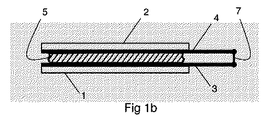
接着領域は、接着性および導電性を有する電気的に脆弱化可能な接着剤を備える。パッケージは、導電性を有し、電気的に脆弱化可能な接着剤に接触している少なくとも1つの活性面をさらに備えることができる。活性面同士の間に電圧をかけると、電気的に脆弱化可能な接着剤を有するボンディング層を通って電流が流れ、ボンディング層内またはボンディング層と少なくとも一方の活性面との間に形成されたボンドが破壊および/または脆弱化される。したがって、ボンディング層は電気的に脆弱化可能な接着剤を形成する。 The adhesive region includes an electrically weakening adhesive having adhesiveness and electrical conductivity. The package may further comprise at least one active surface that is electrically conductive and in contact with an electrically weakening adhesive. When a voltage is applied between the active surfaces, an electric current flows through the bonding layer having an electrically weakening adhesive and is formed in the bonding layer or between the bonding layer and at least one active surface. Bonds are destroyed and / or weakened. Thus, the bonding layer forms an adhesive that can be electrically weakened.
上述のように、接着された紙パッケージは現在、引き剥がしストリップを備えることが少なくない。このパッケージの新しい構成によって、もはやこのような引き剥がしストリップは不要になる。パッケージは、電気的に脆弱化可能な接着剤を使用してパッケージの充填時に接着される。消費者がパッケージを開放したいときには、電気的に脆弱化可能な接着剤に電圧がかけられ、接着剤はその接着力を失う。パッケージはその後、誤って破られる恐れも、再密閉タブ/スロットなどを損傷する恐れも無しに容易に開放される。電気的に脆弱化可能な接着剤を有するパッケージは、現在不可能な方法で設計または構成することもできる。従来のパッケージを構成する際、設計者は、容器の組み立ておよび密閉に関する構成要件と容器の開放に関する構成要件の兼ね合いをとらなければならない。このため、容器の密閉が不必要に複雑になり、しかも容器を必要に応じて開放するのが困難になることが少なくない。この問題は、この新しいパッケージによって解消されるかまたは少なくとも大幅に軽減される。たとえば、単に、連結が必要とされる場所に接着接続部を使用することによって、容器を簡単に組み立てて密閉するのを可能にするように容器を構成することが可能になる。ユーザがパッケージを開放したいときには、電気的に脆弱化可能な接着剤に電圧がかけられ、所望の連結が容易に解除される。このように、パッケージを容易に開放できるようにしたままにしておくにはどうすればよいかに関する広範囲な兼ね合せの必要無しにできるだけ強靭なパッケージを構成することがさらに可能になる。パッケージは、いずれの場合も、電気的に脆弱化可能な接着剤に電圧をかけることによって簡単に開放される。 As mentioned above, bonded paper packages are now often provided with a tear strip. With this new construction of the package, such a stripping strip is no longer necessary. The package is bonded upon filling of the package using an electrically weakening adhesive. When the consumer wants to open the package, a voltage is applied to the electrically weakening adhesive and the adhesive loses its adhesive strength. The package is then easily opened without fear of being accidentally broken or damaging the reseal tab / slot or the like. Packages with electrically weakening adhesives can also be designed or constructed in ways that are not currently possible. When constructing a conventional package, the designer must balance the requirements for assembly and sealing of the container with those for opening the container. For this reason, the sealing of the container is unnecessarily complicated, and it is often difficult to open the container as necessary. This problem is eliminated or at least greatly reduced by this new package. For example, the container can be configured to allow easy assembly and sealing of the container simply by using adhesive connections where coupling is required. When the user wants to open the package, a voltage is applied to the electrically fragile adhesive and the desired connection is easily released. In this way, it is further possible to construct a package that is as strong as possible without the need for extensive tradeoffs on how to keep the package open easily. In any case, the package is simply opened by applying a voltage to the electrically weakening adhesive.
パッケージは、互いに連結され、それによってパッケージを密閉されたままにするようになっている第1の部分および第2の部分を有し、第1および第2の部分が、少なくとも1つの接着領域によって互いに連結され、接着領域が、導電性を有し電気的に脆弱化可能な接着剤を受けるようになっている第1の活性面を有し、第1の活性面が電気的に脆弱化可能な接着剤に電圧をかけるように構成された電気回路の一部を形成する半製品として提供することもできる。 The package has a first portion and a second portion that are coupled together, thereby leaving the package sealed, wherein the first and second portions are defined by at least one adhesive region. Connected to each other, the adhesive region has a first active surface that is adapted to receive an electrically conductive and electrically weakening adhesive, and the first active surface can be electrically weakened It can also be provided as a semi-finished product that forms part of an electrical circuit configured to apply a voltage to an adhesive.
この構成では、パッケージは活性面を備え、一方、電気的に脆弱化可能な接着剤は、パッケージが充填され密閉されるときに活性面に塗布されるようになっている。このパッケージの利点については、上記に、電気的に脆弱化可能な接着剤が接着領域に塗布されたパッケージの実施態様を参照して詳しく論じた。 In this configuration, the package includes an active surface, while an electrically weakening adhesive is applied to the active surface when the package is filled and sealed. The advantages of this package were discussed in detail above with reference to package embodiments in which an electrically weakening adhesive is applied to the bonded area.
同様に、本体およびキャップを有するパッケージの場合、配送時にきつく密閉されしかも容易に開放されるパッケージを提供することが可能である。電気的に脆弱化可能な接着剤は、たとえば、スクリューキャップが誤ってボトルから外されないようにしっかりと固定し、しかも、電圧をかけられた後で、パッケージが開放されるときにキャップをボトルから容易に解放するのに使用することができる。これは、箔で覆われた開口部に使用することもできる。箔は、電気的に脆弱化可能な接着剤を使用してボトルまたはジャーの口部にしっかりと固定される。パッケージが開放されるときには、電圧がかけられ、箔は容易に除去される。それによって、場合によっては、箔を、電圧をかけないかぎり引き剥がすことができなくなるようにしっかりと固定することが可能になる。いずれの場合も、箔を現在よりもしっかりと固定し、しかも現在よりずっと容易に解放するのを可能にすることができる。この固定力の差によって、非常に薄い箔を構成することが可能になる。これは、箔が、電圧をかけられた後、残りの引き剥がし抵抗に耐えるだけでよいからである。これに対して、現在、箔は引き剥がし時に、配送時に箔をパッケージに固定されたままにしておくのに十分な高い抵抗になるように構成された最初の引き剥がし抵抗に耐える必要がある。 Similarly, in the case of a package having a body and a cap, it is possible to provide a package that is tightly sealed and easily opened upon delivery. An electrically fragile adhesive, for example, secures the screw cap so that it is not accidentally removed from the bottle, and after the voltage is applied, the cap is removed from the bottle when the package is opened. Can be used to release easily. This can also be used for openings covered with foil. The foil is securely fastened to the bottle or jar mouth using an electrically fragile adhesive. When the package is opened, a voltage is applied and the foil is easily removed. Thereby, in some cases, the foil can be firmly fixed so that it cannot be peeled off unless a voltage is applied. In either case, the foil can be secured more securely than it is today and still be released much more easily than it is now. This difference in fixing force makes it possible to construct a very thin foil. This is because the foil need only withstand the remaining peel resistance after being energized. In contrast, currently foils need to withstand an initial peel resistance that is configured to be high enough to cause the foil to remain secured to the package upon delivery.
同様に、このパッケージ構成は、第2のパッケージ部材と協働し、それによって密閉されたパッケージを形成するようになっている第1のパッケージ部材を有し、第1のパッケージ部材が、少なくとも1つの接着領域によって第2のパッケージ部材に連結可能になっており、接着領域が、導電性を有し電気的に脆弱化可能な接着剤を受けるようになっている第1の活性面を有し、第1の活性面が電気的に脆弱化可能な接着剤に電圧をかけるように構成された電気回路の一部を形成する半製品として提供するようにすることもできる。 Similarly, the package configuration includes a first package member that cooperates with the second package member to thereby form a sealed package, the first package member being at least one. One adhesive region is connectable to the second package member, the adhesive region having a first active surface adapted to receive an electrically conductive and electrically weakening adhesive. The first active surface may be provided as a semi-finished product that forms part of an electrical circuit configured to apply a voltage to an electrically weakening adhesive.
この構成では、パッケージは活性面を備え、一方、電気的に脆弱化可能な接着剤は、パッケージが充填され密閉されるときに活性面に塗布されるようになっている。このパッケージの利点については、上記に、電気的に脆弱化可能な接着剤が接着領域に塗布されたパッケージの実施態様を参照して詳しく論じた。 In this configuration, the package includes an active surface, while an electrically weakening adhesive is applied to the active surface when the package is filled and sealed. The advantages of this package were discussed in detail above with reference to package embodiments in which an electrically weakening adhesive is applied to the bonded area.
このパッケージは、第1のパッケージ部材と協働し、それによって密閉されたパッケージを形成するようになっている第2のパッケージ部材をさらに有してよい。 The package may further include a second package member adapted to cooperate with the first package member, thereby forming a sealed package.
電気的に脆弱化可能な接着剤を使用すると、最初にパッケージを密閉するときに一体的に形成されるいたずら防止機能を付与することも可能になる。電気的に脆弱化可能な接着剤は、反応すると、もはや同じ高い接着強度には戻らず、それによっていたずら防止機能を実現する。 The use of an electrically weakening adhesive can also provide a tamper-proof function that is integrally formed when the package is first sealed. The electrically brittle adhesive no longer returns to the same high adhesive strength upon reaction, thereby providing a tamper-proof function.
かけられる電圧は、電気的に脆弱化可能な接着剤を脆弱化する所望の方法に応じて交流であっても直流であってもよい。電圧はたとえば、電池などの外部供給源または電磁波によって印加するか、あるいはそれぞれの異なる電位を有する互いに異なる材料の活性面を有するパッケージを構成し、それによって内部電池を形成することによって印加することもできる。 The applied voltage may be alternating current or direct current depending on the desired method of weakening the electrically weakening adhesive. The voltage can be applied, for example, by an external source such as a battery or electromagnetic waves, or by forming a package having active surfaces of different materials with different potentials, thereby forming an internal battery. it can.
パッケージは、導電性を有し、互いに距離を置いて配置され、電気回路を介して互いに電気的に接続可能になっている第1および第2の活性面をさらに有してよく、この場合、電気的に脆弱化可能な接着剤は、第1の活性面と第2の活性面との間の距離を埋めるようになっている。このように、電気的に脆弱化可能な接着剤の両端間に制御可能に電圧をかけることが可能になる。2つの活性面は、2つの異なる電極電位に接続可能であり、それによって、電気的に脆弱化可能な接着剤の両端間に電圧を生じさせる。上述のように、電圧はいくつかの方法でかけることができる。 The package may further include first and second active surfaces that are electrically conductive, spaced apart from each other, and electrically connectable to each other via an electrical circuit, where The electrically embrittleable adhesive fills the distance between the first active surface and the second active surface. In this way, it is possible to controllably apply voltage across the electrically brittle adhesive. The two active surfaces can be connected to two different electrode potentials, thereby creating a voltage across the electrically weakening adhesive. As mentioned above, the voltage can be applied in several ways.
電気的に脆弱化可能な接着剤は、密封層を形成することができる。このように、しっかりと密封されしかも容易に開放することのできるパッケージを形成することが可能である。 An electrically brittle adhesive can form a sealing layer. In this way, it is possible to form a package that is tightly sealed and that can be easily opened.
パッケージは、非導電材料で形成することができる。このように、活性面などの導体は、単に非導電材料上の印刷導体または積層導体として設けることができる。絶縁層を含むより複雑な積層構造は当面必要にならない。 The package can be formed of a non-conductive material. Thus, conductors such as active surfaces can simply be provided as printed conductors or laminated conductors on non-conductive materials. More complicated laminated structures including insulating layers are not necessary for the time being.
パッケージは、板紙またはプラスチックで形成することができる。連結部材またはパッケージを板紙またはプラスチックで設けることが容易なのでこれらの材料のいずれかが好ましい。プラスチックまたは板紙はまた、通常非導電性であり、たとえば、印刷技術または積層技術を使用してプラスチックまたは板紙に電気回路を設けることは容易である。 The package can be formed of paperboard or plastic. Any of these materials is preferred because it is easy to provide the connecting member or package with paperboard or plastic. Plastic or paperboard is also usually non-conductive and it is easy to provide an electrical circuit on the plastic or paperboard using, for example, printing or lamination techniques.
パッケージは、閉電気回路においてそれぞれの接着領域に電圧を印加するように作動させられるかまたは導体に接続されるようになっている内部電源を有してよい。このように、パッケージは、どこで開放することもでき、かつ誰でも開放することができる。 The package may have an internal power source that is actuated to apply a voltage to the respective bond area in a closed electrical circuit or is connected to a conductor. In this way, the package can be opened anywhere and anyone can open it.
第1の活性面は、第1の電極電位を有する第1の材料で作ることができ、第2の活性面は、第2の電極電位を有する第2の材料で作ることができ、第1の電極電位は第2の電極電位とは異なる。このように、このような活性面は、内部電源として働き、電気的に脆弱化可能な接着剤の外側で電気回路を介して互いに接続されると、電気的に脆弱化可能な接着剤の両端間に電圧をかける閉電気回路を形成する。 The first active surface can be made of a first material having a first electrode potential, and the second active surface can be made of a second material having a second electrode potential, Is different from the second electrode potential. Thus, such an active surface acts as an internal power source and when connected to each other via an electrical circuit outside the electrically weakening adhesive, both ends of the electrically weakening adhesive A closed electric circuit in which a voltage is applied in between is formed.
連結部材またはパッケージは、少なくとも1つの印刷電池および/または積層電池をさらに有してよい。これは、内部電源を設ける好都合な方法である。 The connecting member or package may further include at least one printed battery and / or stacked battery. This is a convenient way of providing an internal power supply.
少なくとも1つの印刷電池および/または積層電池は第1の担体層上に印刷することができる。これは、内部電源を形成する電池を設ける好都合な方法である。指摘したように、第1の担体層を使用して1つまたは2つ以上の活性面を保持することもできる。それによって、電池と第1の担体層上の1つまたは2つ以上の活性面との間に接続部を設けることが容易になる。 At least one printed battery and / or laminated battery can be printed on the first carrier layer. This is a convenient way of providing a battery that forms the internal power supply. As pointed out, the first carrier layer can also be used to hold one or more active surfaces. This facilitates providing a connection between the battery and one or more active surfaces on the first carrier layer.
パッケージは、第1の面を含む第1の担体層をさらに有してよく、第1および第2の活性面が担体層によって支持され、この場合、第1の活性面は、第1の担体層の面に沿って第2の活性面から第1の距離だけ分離され、積層構造は、活性面同士の間の距離を埋める電気的に脆弱化可能な接着剤を受けるようになっている。 The package may further comprise a first carrier layer including a first surface, wherein the first and second active surfaces are supported by the carrier layer, wherein the first active surface is the first carrier. Separated from the second active surface by a first distance along the plane of the layer, the laminate structure is adapted to receive an electrically weakening adhesive that fills the distance between the active surfaces.
このように、単一の担体層上に活性面を有する構造の部品を事前に製造することが可能になる。パッケージが密閉されるときに、電気的に脆弱化可能な接着剤が活性面に塗布され、接着剤上に第2の担体層が配置され、それによって、パッケージの第1および第2の部分(または第1および第2の部材)が互いに連結される。この構成はまた、両方の活性面を電気的に脆弱化可能な接着剤の同じ側に設け、それによってパッケージ部材の同じ部分に設けるのを可能にする。このような構成は、任意の回路を設けるのを容易にする。なぜなら、このような場合の回路は、第1の部分と第2の部分(または第1のパッケージ部材と第2のパッケージ部材)との間の界面を形成する必要がないからである。 In this way, it is possible to pre-manufacture parts with a structure having an active surface on a single carrier layer. When the package is sealed, an electrically fragile adhesive is applied to the active surface and a second carrier layer is disposed on the adhesive, whereby the first and second portions of the package ( Alternatively, the first and second members) are connected to each other. This configuration also allows both active surfaces to be provided on the same side of the electrically fragile adhesive, thereby providing the same portion of the package member. Such a configuration makes it easy to provide an arbitrary circuit. This is because the circuit in such a case does not need to form an interface between the first portion and the second portion (or the first package member and the second package member).
第1の活性面は、第2の活性面から第1の活性面の法線方向にある距離だけ分離することができ、電気的に脆弱化可能な接着剤は第1の活性面と第2の活性面との間の距離を埋めることができる。このような構成の1つの利点は、電気的に脆弱化可能な接着剤と活性面との間に大きな接触界面を形成するのが比較的容易であることである。さらに、電気的に脆弱化可能な接着剤によって埋められる距離は、大きい界面全体にわたって同一に維持することができ、制御された結合解除を可能にする。 The first active surface can be separated from the second active surface by a distance in the normal direction of the first active surface, and the electrically weakening adhesive can be separated from the first active surface and the second active surface. The distance between the active surface can be filled. One advantage of such a configuration is that it is relatively easy to form a large contact interface between the electrically weakening adhesive and the active surface. Further, the distance filled by the electrically weakening adhesive can be kept the same across a large interface, allowing for controlled decoupling.
この構成はたとえば、電圧が外部電圧によってかけられる場合にも使用することができる。第1の活性面は第2のコネクタ部を備え、それによって、外部電圧源がコネクタ部に接続され、電圧が電気的に脆弱化可能な接着剤の両端間にかけられる。 This configuration can also be used, for example, when the voltage is applied by an external voltage. The first active surface comprises a second connector part, whereby an external voltage source is connected to the connector part and a voltage is applied across the adhesive that can be electrically weakened.
第1の部分または第1のパッケージ部材は第1の担体層を形成することができる。第1のパッケージ部材は、ボトルやジャーなどの容器本体を形成することができ、第2のパッケージ部材は、キャップなどのクロージャ部材を形成することができる。しかし、他の実施態様では、第1のパッケージ部材がクロージャ部材を形成し、第2のパッケージ部材が容器本体を形成する。パッケージのどの部分が第1および第2の部分(または部材)を形成するかの厳密な選択は、特にそれぞれの異なる部分について選択される材料に依存する。容器本体が紙で作られる場合、利用可能な面積が、どこに活性面を配置するかを決定することが少なくない。容器本体がガラスで作られ、キャップがプラスチックで作られる場合、キャップに必要な回路を設け、容器本体を、プラスチック製キャップを有する従来のガラス製ボトルと基本的に同じ状態にしておくと好都合であることがある。ボトルがプラスチックで作られる場合、ボトル首部に必要な回路を設けると好都合であることがある。通常、スクリューキャップがボトル首部にかなり厳密に揃えられ、それによって、回路のいくつかの部品をボトル首部に設け、他の部品をキャップに設けることができる。 The first portion or the first package member can form a first carrier layer. The first package member can form a container body such as a bottle or a jar, and the second package member can form a closure member such as a cap. However, in other embodiments, the first package member forms a closure member and the second package member forms a container body. The exact choice of which part of the package forms the first and second part (or member) depends in particular on the material selected for each different part. When the container body is made of paper, the available area often determines where to place the active surface. If the container body is made of glass and the cap is made of plastic, it is convenient to provide the necessary circuitry for the cap and keep the container body essentially the same as a conventional glass bottle with a plastic cap. There may be. If the bottle is made of plastic, it may be advantageous to provide the necessary circuitry at the bottle neck. Typically, the screw cap is fairly closely aligned with the bottle neck so that some parts of the circuit can be provided on the bottle neck and other parts on the cap.
少なくとも一方の活性面の一部を露出させ、接着剤で覆われるように構成することができる。このように、電気的に脆弱化可能な接着剤自体がこの活性面との導電ブリッジを形成する。 A part of at least one active surface may be exposed and covered with an adhesive. Thus, the electrically weakening adhesive itself forms a conductive bridge with this active surface.
第1の活性面の少なくとも一部および第2の活性面の少なくとも一部が露出され、接着剤で覆われるようになっている。このように、電気的に脆弱化可能な接着剤自体が両方の活性面との導電ブリッジを形成する。 At least a portion of the first active surface and at least a portion of the second active surface are exposed and covered with an adhesive. In this way, the electrically weakening adhesive itself forms a conductive bridge with both active surfaces.
活性面は、担体層の面上の第1の活性面の突起が担体層の面上の第2の活性面の突起をほぼ囲むように形作ることができる。このように、電気的に脆弱化可能な接着剤が破壊または脆弱化される面積は、活性面のサイズと比べて比較的大きい。このように、活性面内の抵抗によるエネルギー損失は最小限に抑えられる。さらに、接着剤のかなり集中した脆弱化が可能になり、パッケージを開放するのが容易になる。 The active surface can be shaped such that the protrusions of the first active surface on the surface of the carrier layer substantially surround the protrusions of the second active surface on the surface of the carrier layer. Thus, the area where the electrically weakening adhesive is destroyed or weakened is relatively large compared to the size of the active surface. Thus, energy loss due to resistance in the active plane is minimized. In addition, the adhesive can be heavily concentrated, making it easier to open the package.
第1の面上の第1の活性面の突起と第1の面上の第2の活性面の突起は少なくとも部分的に互いに重なり合い、この積層構造は、第1の活性面と第2の活性面との間の、少なくとも重なり合った部分に設けられた絶縁層をさらに有する。間に重なり合った部分および絶縁層を有する活性面を設けることによって、担体層の平面内の分離によって制限する必要無しに、電気的に脆弱化される領域を最適化することが可能になる。 The protrusions of the first active surface on the first surface and the protrusions of the second active surface on the first surface at least partially overlap each other, and the stacked structure includes the first active surface and the second active surface It further has an insulating layer provided at least in an overlapping portion between the surfaces. By providing an active surface with an overlapped portion and an insulating layer in between, it is possible to optimize the electrically weakened region without having to be limited by in-plane separation of the carrier layer.
第1の活性面は、第1の担体層の面上の第1の活性面の突起が第1の担体層の面上の第2の活性面の突起を囲む閉ループとして形成することができ、第2の活性面は、第1の活性面の閉ループから延びる連結部を有し、電気絶縁層は、第1の活性面から連結部を分離する。このように、電位は、電気的に脆弱化可能な接着剤によって第2の活性面を迂回して第1の活性面に渡される。これによって、脆弱化される面積は第2の活性面のサイズと比べて比較的大きくなる。 The first active surface can be formed as a closed loop in which the protrusions of the first active surface on the surface of the first carrier layer surround the protrusions of the second active surface on the surface of the first carrier layer; The second active surface has a connecting portion extending from the closed loop of the first active surface, and the electrical insulating layer separates the connecting portion from the first active surface. In this way, the potential is passed to the first active surface by bypassing the second active surface by an electrically weakening adhesive. As a result, the area to be weakened is relatively large compared to the size of the second active surface.
パッケージは、活性面同士の間の距離を埋め、活性面と第2の担体層との間に配置されるようになっている電気的に脆弱化可能な接着剤をさらに有してよい。たとえば、パッケージ上に活性面が設けられているが電気的に脆弱化可能な接着剤を有さないパッケージを食品販売業者に販売できることに留意されたい。この場合、電気的に脆弱化可能な接着剤は、パッケージが密閉されるときに塗布することができる。 The package may further include an electrically embrittleable adhesive that fills the distance between the active surfaces and is arranged between the active surface and the second carrier layer. For example, it should be noted that packages that have an active surface on the package but do not have an electrically fragile adhesive can be sold to food distributors. In this case, the electrically weakening adhesive can be applied when the package is sealed.
パッケージは、電気的に脆弱化可能な接着剤と第2の担体層との間に配置されるようになっている層として設けられた電気的に脆弱化不能な接着剤をさらに有してよい。このように、活性面および電気的に脆弱化可能な接着剤を有する構造を事前に製造し、次にパッケージが初めて密閉されるときに、この上に従来の接着剤を塗布することが可能である。パッケージが開放されるときには、電気的に脆弱化可能な接着剤が脆弱化され、従来の接着剤が、活性面を保持していない部分またはパッケージと一緒に取り外される。電気的に脆弱化可能な接着剤の2つの層を、一方の層を事前製造ステップで設け、第2の層を、パッケージが密閉されるときに設けることも考えられる。 The package may further comprise an electrically non-fragile adhesive provided as a layer adapted to be disposed between the electrically weakened adhesive and the second carrier layer. . In this way, it is possible to pre-manufacture a structure with an active surface and an electrically weakening adhesive and then apply a conventional adhesive onto it when the package is then sealed for the first time. is there. When the package is opened, the electrically weakening adhesive is weakened and the conventional adhesive is removed along with the part or package that does not hold the active surface. It is also conceivable to provide two layers of adhesive that can be electrically weakened, one layer being provided in a pre-manufacturing step and the second layer being provided when the package is sealed.
パッケージは、電気的に脆弱化可能な接着剤または電気的に脆弱化不能な接着剤によって第1の担体層および活性面に接着された第2の担体層をさらに有してよい。 The package may further include a first carrier layer and a second carrier layer bonded to the active surface with an electrically weakening adhesive or an electrically non-weakening adhesive.
本発明は、少なくとも1つの接着領域によって互いに連結され、それによってパッケージを密閉されたままにしておくようになっている第1の部分および第2の部分を有するパッケージ本体を設けることと、少なくとも1つの接着領域に電気的に脆弱化可能な接着剤を塗布することと、第1の部分および第2の部分を少なくとも1つの接着領域において互いに連結し、それによってパッケージを密閉することとを含む方法を含むとも言える。このようにして、たとえば、フラップ部または一体化されたふたを備えたパッケージは好都合に密閉される。 The present invention provides a package body having a first portion and a second portion that are connected to each other by at least one adhesive region, thereby leaving the package sealed. Applying an electrically fragile adhesive to one adhesive region and connecting the first and second portions together in the at least one adhesive region, thereby sealing the package It can be said that it includes. In this way, for example, a package with a flap or an integrated lid is conveniently sealed.
本発明は、少なくとも1つの接着領域によって互いに連結され、それによって密閉されたパッケージを形成するようになっている第1のパッケージ部材および第2のパッケージ部材を設けることと、少なくとも1つの接着領域に電気的に脆弱化可能な接着剤を塗布することと、第1のパッケージ部材を少なくとも1つの接着領域において第2のパッケージ部材に連結し、それによってパッケージを密閉することとを含む方法を含むとも言える。このようにして、ボトルおよびキャップやジャーおよびふたのような2つまたは3つ以上の別個のパッケージ部材で形成されたパッケージは、好都合に密閉される。 The present invention provides a first package member and a second package member connected to each other by at least one adhesive region, thereby forming a hermetically sealed package, and the at least one adhesive region And applying a electrically brittle adhesive and coupling the first package member to the second package member in at least one adhesive region, thereby sealing the package. I can say that. In this way, packages formed with two or more separate package members such as bottles and caps, jars and lids are conveniently sealed.
一実施態様では、パッケージの第1および第2の部分または第1のパッケージ部材および第2のパッケージ部材は、電気的に脆弱化可能な接着剤によって互いに連結される。このように、パッケージを密閉するのに、余分な接着剤は必要とされない。 In one embodiment, the first and second portions of the package or the first package member and the second package member are coupled together by an electrically weakening adhesive. Thus, no extra adhesive is required to seal the package.
他の実施態様では、パッケージの第1の部分および第2の部分または第1のパッケージ部材および第2のパッケージ部材は、電気的に脆弱化可能である必要のない第2の接着剤によって互いに連結される。このように、構造の各部品を事前に製造することが可能である。 In other embodiments, the first and second portions of the package or the first and second package members are connected to each other by a second adhesive that need not be electrically fragile. Is done. In this way, it is possible to manufacture each part of the structure in advance.
これらの方法は、電気的に脆弱化可能な接着剤の両端間に電圧をかけることをさらに含んでよい。このようにして、上記に詳しく論じたように、電気的に脆弱化可能な接着剤のボンドが脆弱化また破壊される。 These methods may further include applying a voltage across the electrically weakening adhesive. In this way, as discussed in detail above, the electrically bondable adhesive bond is weakened or broken.
この方法は、第1の部分または第1のパッケージ部材を第2の部分または第2のパッケージ部材から分離することによってパッケージを開放することをさらに含んでよい。このようにして、電気的に脆弱化可能な接着剤の脆弱化されたボンドが破壊され、パッケージは容易に開放される。 The method may further include opening the package by separating the first portion or first package member from the second portion or second package member. In this way, the weakened bond of the electrically weakenable adhesive is broken and the package is easily opened.
本発明について、一例として、本発明の好ましい実施形態を示す添付の概略図を参照して詳しく説明する。 The invention will now be described in detail by way of example with reference to the accompanying schematic diagram illustrating a preferred embodiment of the invention.
以下に説明するパッケージは、電気的に脆弱化可能な接着剤材料を利用する。本発明のパッケージは、電気的に脆弱化可能な接着剤材料によって形成されるボンディング層に連結された電子および/またはイオンエミッタおよびレシーバとして働く2つの活性面を備えている。ボンディング層は、接着性および導電性を有している。活性面同士の間に電圧がかけられ、ボンディングを通って電流が流れると、ボンディング層内またはボンディング層と少なくとも一方の活性面との間に形成されたボンドが破壊または脆弱化される。したがって、ボンディング層は電気的に脆弱化可能な接着剤を形成する。 The package described below utilizes an adhesive material that can be electrically weakened. The package of the present invention comprises two active surfaces that act as electron and / or ion emitters and receivers coupled to a bonding layer formed by an electrically brittle adhesive material. The bonding layer has adhesiveness and conductivity. When a voltage is applied between the active surfaces and a current flows through the bonding, the bond formed in the bonding layer or between the bonding layer and at least one active surface is broken or weakened. Thus, the bonding layer forms an adhesive that can be electrically weakened.
電気的に脆弱化可能な接着剤は、活性層同士の間の距離を完全に埋めることができるが、必要な電気的および/または機械的接続を行うことのできる他の材料の追加の層を備えてもよい。このような材料は、従来の非導電接着剤、ポリマー、ワニスなど、またはそれぞれの材料の導電形態であってよい。 The electrically brittle adhesive can completely fill the distance between the active layers, but does not include additional layers of other materials that can make the necessary electrical and / or mechanical connections. You may prepare. Such materials may be conventional non-conductive adhesives, polymers, varnishes, etc., or the conductive form of the respective material.
まず、電気的に脆弱化可能な接着剤および活性面の様々な基本構成について、パッケージの特定の構成とは別に詳しく論じる。その後、パッケージの様々な構成について詳しく論じる。場合によっては、パッケージの構成について特定の種類の基本構成と組み合わせて論じる。しかし、これが例示のためのものであり、様々な基本構成をパッケージの様々な構成と組み合わせることができることに留意されたい。 First, the various basic configurations of adhesives and active surfaces that can be electrically weakened will be discussed in detail separately from the specific configuration of the package. Then, the various configurations of the package are discussed in detail. In some cases, package configurations are discussed in combination with certain types of basic configurations. However, it should be noted that this is for illustration and various basic configurations can be combined with various configurations of the package.
一実施形態によれば、ボンディング層は、マトリックス機能と電解機能の両方を有する組成で構成されている。マトリックス機能および電解機能は、単一の相またはいくつかの別個の相によって形成することができる。 According to one embodiment, the bonding layer is composed of a composition having both a matrix function and an electrolytic function. The matrix function and the electrolysis function can be formed by a single phase or several distinct phases.
マトリックス機能は、面同士を互いに機械的または化学的に結合するのに必要な接着性を実現する。マトリックス機能は、接着性を有するポリマー、ポリマー樹脂、または繊維によって実現することができる。 The matrix function provides the adhesion necessary to mechanically or chemically bond the surfaces together. The matrix function can be realized by an adhesive polymer, polymer resin, or fiber.
電解機能は、ファラデー反応、すなわち、材料が酸化または還元させられる電気化学反応、あるいは他の何らかの化学/物理反応を生じさせるのに必要なイオン伝導性を実現する。各材料は、反応が一方または両方の活性面とボンディング層との間の界面で生じるように選択され構成されることが好ましい。あるいは、反応がボンディング層内で生じるようにボンディング層を構成することができる。これはたとえば、マトリックス材料内に電解機能を有するアイランド状の材料を設けることによって実現することができる。電解機能は、材料に塩を添加するかまたはポリマーがイオン配位部分を含むようにポリマーを修飾することによって実現することができる。 The electrolytic function achieves the Faraday reaction, that is, the ionic conductivity necessary to cause an electrochemical reaction in which the material is oxidized or reduced, or some other chemical / physical reaction. Each material is preferably selected and configured such that the reaction occurs at the interface between one or both active surfaces and the bonding layer. Alternatively, the bonding layer can be configured such that the reaction occurs within the bonding layer. This can be achieved, for example, by providing an island-like material having an electrolytic function in the matrix material. The electrolysis function can be achieved by adding a salt to the material or by modifying the polymer such that the polymer includes an ionic coordination moiety.
本発明のパッケージで使用される電気的に脆弱化可能な接着剤は、EIC研究所(laboratories)から供給されており、米国特許第6620308号に詳しく開示された電気化学的に結合解除可能な組成ElectreleaseTMであってよい。 The electrofragile adhesive used in the package of the present invention is supplied by EIC laboratories and is disclosed in detail in US Pat. No. 6,620,308 as an electrochemically debondable composition. It can be Electrelease TM .
図1a〜1cは、ボンディング層のボンドを破壊または脆弱化するのに電気エネルギーをどのように印加するかについての3つの異なる実施形態を有する共通基本構造を示している。 FIGS. 1 a-1 c show a common basic structure with three different embodiments of how electrical energy is applied to break or weaken the bonds in the bonding layer.
この基本構造は、第1の担体層1と第2の担体層2とを有している。第1の活性層3が第1の担体層1上に積層されている。第2の活性層4が第2の担体層2上に積層されている。活性層は、電気的に脆弱化可能な接着剤を有するボンディング層5によって互いに結合されている。
This basic structure has a
図1aでは、活性層3、4間の電位差は、電気エネルギー(+符号および−符号によって示されている)の外部供給源6から与えられるようになっている。この外部供給源はたとえば、手持ち装置に設けられた電池、またはパッケージに取り付けられ活性層3、4に接続可能な電池であってよい。1つまたはいくつかの電池をたとえば、一方の担体層上に印刷して活性面に接続することができる。この構成では、2つの活性層3、4を同じ材料で形成することができるが、そうしなくてもよい。活性面3、4間に電圧がかけられると、ボンディング層5を介して活性面3、4間に電流が流れる。これによって、ボンディング層5内あるいはボンディング層5と一方または両方の活性面3、4との間のボンドが破壊または脆弱化される。印加される電流は、直流の形であっても交流の形であってもよい。ボンディング層5内または一方の活性面3もしくは4とボンディング層5との間のボンドを脆弱化するには直流を使用することが好ましい。ボンディング層5内または両方の活性面3、4とボンディング層5との間のボンドを脆弱化するには交流を使用することが好ましい。
In FIG. 1 a, the potential difference between the
図1bでは、活性面3、4間の電位差は、それぞれの異なる電位を有する互いに異なる材料の活性層3、4を作ることによって得られるようになっている。たとえば、2つの活性層3、4が、スイッチ7を、2つの層3、4を接続する位置まで移動させることによって接続される場合、閉回路が形成され、ボンディング層5を通って電流が流れ、それによって接着剤ボンドが破壊または脆弱化される。たとえば、それぞれの異なる電位を有する活性層3、4として銅および黒鉛を使用することができる。この構成は、ボンディング層5を介して活性層3、4間に直流電流を生じさせる。
In FIG. 1b, the potential difference between the
図1cでは、活性層3、4間の電位差は、電磁波、たとえば電波をパッケージに供給することによって得られる。活性層3、4または活性層3、4に連結された別個の部材8を、電磁波を受け、この波を活性層3、4間の電位差に変換するように構成することができる。電磁波によって生成されるAC電圧を直接使用するかまたは整流器、たとえば、活性面に接続された半波整流器や全波整流器によってDC電圧に変換することができる。部材8は、たとえばアンテナやコイルであってよい。この構成では、2つの活性層3、4を同じ材料で形成することができるが、そうしなくてもよい。
In FIG. 1c, the potential difference between the
図2〜5は、活性面が担体層の同じ側に配置された実施形態を示している。図2、3、および5では、互いに異なる層が、明確な理由で互いに距離を置いて示されている。しかし、実際には各層が積層構造を形成することは明らかである。以下の説明から、互いに異なる開示された層が互いに接触する必要があるのはどの場合か、および開示されていない他の1つまたは2つ以上の層を設けてよいのはいつかが明らかになる。直接的な接触が、状況に応じて機械的接触または電気的接触を意味することに留意されたい。さらに図1a〜1cで論じられる電圧を印加する様々な方法に関する教示は、図2〜5の実施形態にも適用可能である。 Figures 2 to 5 show embodiments in which the active surface is arranged on the same side of the carrier layer. In FIGS. 2, 3 and 5, different layers are shown spaced apart from each other for obvious reasons. However, it is clear that each layer actually forms a laminated structure. From the following description, it will become apparent when different disclosed layers need to contact each other and when one or more other undisclosed layers may be provided. . Note that direct contact means mechanical or electrical contact depending on the situation. Furthermore, the teachings regarding the various methods of applying the voltage discussed in FIGS. 1a-1c are also applicable to the embodiments of FIGS.
図2は、活性面3、4が、図1a〜1cと同様にボンディング層5の各側に2つの別個の層3、4として設けられるのではなく、ボンディング層の同じ側に配置されることを示している。この構造は、剥離される2つの担体層1、2を有している。担体層1、2はたとえば、紙、板紙、またはプラスチックで作ることができるが、他の材料も考えられる。活性面3、4は、ボンディング層5の一方の側に配置され、担体層1の面5aに沿って互いに距離dだけ分離されている。
FIG. 2 shows that the
活性面3、4は、従来の方法を使用して第1の担体層1に貼り付けることができ、たとえば、担体層1上に印刷または積層することができる。活性面3、4は、任意の導電材料、たとえば金属インクや箔で作ることができる。ボンディング層5は、それぞれの活性面3、4と第2の担体層2との間に設けられ、それによって活性面3、4を第2の担体層2に結合し、それによって2つの担体層1、2を互いに結合する。ボンディング層5は通常、活性面3、4間の隙間または距離dによって形成される小さい接近可能領域において第1の担体層1に達する。図2に示されているように、一方の活性面3は、他方の活性面4を部分的に囲む開いた半円として形成された分散領域を有している。この他方の活性面4は、円として形成された分散領域を有している。2つの活性面3、4は、上述の距離dによって形成される幅を有する、リングの一部、この場合には円環の一部として形成される隙間を形成する。
The
活性面3、4はまた、外部電源6およびスイッチ7を有する回路9を介して互いに接続されるかまたは接続可能である。
The
たとえば、スイッチ7を閉じることによって活性面3、4間に電圧がかけられると、ボンディング層5を介して活性面3、4間に電流が流れる。これによって、ボンディング層5内またはボンディング層5と一方もしくは両方の活性面3、4との間のボンドが破壊または脆弱化される。活性面3、4間の第1の担体層1の接近可能領域は、ボンディング層5が第1の担体層1に達する場合でも、この接近可能領域とボンディング層5との間のボンドを破壊するのに必要な力が無視できるものになるほど小さくすることができる。
For example, when a voltage is applied between the
電源6はたとえば、担体層1上に印刷または積層され活性面3、4に接続された少なくとも1つの電池であってよい。このように、電池6および活性面3、4は、同じプロセスステップで担体層上に印刷または積層することができる。電源を増大するには、いくつかの電池を担体層1上に印刷し活性面に接続することができる。これによって、すべての電池および活性面を同じプロセスステップで担体層上に印刷することが可能になり、構造の製造が容易になる。
The
図2に示されている実施形態に対する他の実施形態では、活性面3、4は、それぞれの異なる電位を有する互いに異なる材料で形成される。このような実施形態では、外部電源6を無くすることができる。回路9がスイッチ7によって閉じられると、ボンディング層5を介して活性面3、4間に電流が流れ、ボンディング層5内あるいはボンディング層5と一方または両方の活性面3、4との間のボンドが破壊または脆弱化される。
In another embodiment relative to the embodiment shown in FIG. 2, the
図3および4は、図2に示されているのと同様の種類の他の実施形態を示している。図3および4の実施形態では、活性面3、4は、絶縁層10によって平面外に分離されているが、依然として、第2の担体層2に対してボンディング層5の同じ側に配置されている。第1の活性面3は、図2の実施形態では第1の活性面3の一部を形成していたコネクタ3aに電気的に接続されている。
3 and 4 show another embodiment of the same type as shown in FIG. In the embodiment of FIGS. 3 and 4, the
絶縁層10は、導電部材同士を分離し、かつ引き剥がしおよび摩耗から保護する。コネクタ3aは、第1の活性面3に接触しているが、コネクタ3aと第2の活性面4は直接接続されていない。
The insulating
第2の活性面4は、図2の実施形態と同様に担体層1上に設けられている。絶縁層10は、この構造上に設けられている。絶縁層10の上方に第1の活性面3が配置されており、最後にこの上にボンディング層5が配置されている。第1および第2の活性面3、4は平面外に分離されているので、第1の活性面3は、第2の活性面4の円形端部全体を囲む円形部材として形成することができる。活性面3、4および絶縁層10は、ボンディング層5によって埋められるようになっている活性面3、4間の隙間を形成する。ボンディング層5は、第2の担体層2から第1の担体層1まで延び、それによって第1および第2の担体層1、3を直接接着する。
The second
活性面3、4はまた、外部電源6およびスイッチ7を有する回路9を介して互いに接続されるかまたは接続可能である。
The
たとえば、スイッチ7を閉じることによって活性面3、4間に電圧がかけられると、ボンディング層5を介して活性面3、4間に電流が流れる。これによって、ボンディング層5内またはボンディング層5と一方もしくは両方の活性面3、4との間のボンドが破壊または脆弱化される。活性面3、4間の第1の担体層1の接近可能領域は、ボンディング層5が第1の担体層1に達する場合でも、この接近可能領域とボンディング層5との間のボンドを破壊するのに必要な力が無視できるものになるほど小さくすることができる。
For example, when a voltage is applied between the
図3および4に示されている実施形態に対する他の実施形態では、活性面3、4は、それぞれの異なる電位を有する互いに異なる材料で形成される。このような実施形態では、外部電源6を無くすることができる。回路9がスイッチ7によって閉じられると、ボンディング層5を介して活性面3、4間に電流が流れ、ボンディング層5内あるいはボンディング層5と一方または両方の活性面3、4との間のボンドが破壊または脆弱化される。
In another embodiment relative to the embodiment shown in FIGS. 3 and 4, the
図5は、図3および4に示されている実施形態に対する他の実施形態を示しており、ボンディング層5は、第2のボンディング層11を保持するようになっている。この第2のボンディング層11は、導電性である必要も電気的に脆弱化可能である必要もない接着剤で形成することができる。この第2のボンディング層を形成することによって、活性面3、4を有する第1の担体層1およびボンディング層5を事前に形成し、次いで最後に、第2の担体層2が第1の担体層1に固定されるときに電気的に脆弱化可能なボンディング層5上に第2のボンディング層11を貼り付けることが可能である。この追加のボンディング層11は、図2に示されている構成で使用することもできる。
FIG. 5 shows another embodiment relative to the embodiment shown in FIGS. 3 and 4, where the
当業者には、上記に開示された実施形態の他のいくつかの実施形態および上記に開示された実施形態の組み合わせが存在することが認識されよう。これらの他のいくつかの実施形態について以下に簡単に説明する。 One skilled in the art will recognize that there are several other embodiments of the above disclosed embodiments and combinations of the above disclosed embodiments. Some of these other embodiments are briefly described below.
それぞれの活性面/層は、それぞれの担体層上に直接的にまたは積層などを介して間接的に配置することができる。活性層自体が活性面と担体層の両方を形成することができる。 Each active surface / layer can be placed directly on each carrier layer or indirectly, such as via lamination. The active layer itself can form both the active surface and the carrier layer.
上述のように、活性面は、平面内で、および/または平面外に分離することができる。活性面を平面外に分離するときには、絶縁層、たとえばワニスを使用することができる。担体層が導電性を有するときに、絶縁層を使用して、活性面などの導電部材を担体層から分離することもできる。たとえばボンディング層と第2の担体層との間に追加の導体を配置して構造の平面内の導電性を高めることができる。 As mentioned above, the active surfaces can be separated in a plane and / or out of plane. When separating the active surface out of the plane, an insulating layer, such as a varnish, can be used. When the carrier layer is conductive, an insulating layer can be used to separate the conductive member such as the active surface from the carrier layer. For example, additional conductors can be placed between the bonding layer and the second carrier layer to increase conductivity in the plane of the structure.
活性面は、導電面、導体であり、好ましくは、少なくとも一方の担体層上に被覆、印刷、または積層される。しかし、担体層が導電性を有する場合、余分な活性面は必要とされない。活性面は導電材料、たとえば、銅、アルミニウム、または黒鉛で構成することができる。活性面はたとえば、金属インクの形であってもよい。 The active surface is a conductive surface or a conductor, and is preferably coated, printed, or laminated on at least one carrier layer. However, if the carrier layer is conductive, no extra active surface is required. The active surface can be composed of a conductive material such as copper, aluminum, or graphite. The active surface may be, for example, in the form of metallic ink.
担体層は、電気力によって剥離される面に相当し、任意の導電材料または非導電材料、たとえば、紙、板紙、ガラス、金属、木、成形繊維、またはプラスチックで作ることができる。たとえば、パッケージの開口部の互いに向かい合う2つの側は、第1および第2の担体層に相当する。これについて以下に詳しく論じる。 The carrier layer corresponds to the surface to be peeled off by electric force and can be made of any conductive or non-conductive material, for example paper, paperboard, glass, metal, wood, molded fiber, or plastic. For example, the two opposite sides of the package opening correspond to first and second carrier layers. This is discussed in detail below.
一実施形態によれば、担体層はカートン用板紙で形成され、活性層は酸化物を含むアルミニウム箔で形成される。活性面は、塩溶液でされ、ポリウレタンを含む組成物を使用して結合される。積層構造上に電圧がかけられると、正に荷電された箔上の酸化アルミニウムが溶解し、それによって積層体が破壊される。電気力は、上記および図1a〜1cに引用された方法のいずれかによって印加することができる。 According to one embodiment, the carrier layer is formed from carton paperboard and the active layer is formed from an aluminum foil containing oxide. The active surface is made with a salt solution and bonded using a composition comprising polyurethane. When a voltage is applied over the laminate structure, the aluminum oxide on the positively charged foil dissolves, thereby destroying the laminate. The electrical force can be applied by any of the methods described above and cited in FIGS.
この構造の剥離は、構造の残留内部ひずみによってより容易に行うことができる。たとえば、ゴム製リングを使用して弾性ひずみを形成することができる。電気的に脆弱化可能な接着剤をゴム製リングの周りに塗布することができ、硬化時にゴム製リングを押し付けることができる。たとえば、これを使用して、ユーザが電圧をかけることによって接着剤中のボンドが脆弱化または破壊されたときに製品が飛び出す「自己開放」パッケージを作製することができる。 Separation of this structure can be performed more easily due to residual internal strain of the structure. For example, a rubber ring can be used to create the elastic strain. An electrically fragile adhesive can be applied around the rubber ring and the rubber ring can be pressed upon curing. For example, it can be used to create a “self-opening” package where the product pops up when the bond in the adhesive is weakened or broken by the user applying a voltage.
上述のように担体層、活性面、および電気的に脆弱化可能な接着剤を有する剥離材料構造は、シールの強度を弱める必要があるときに使用することができ、たとえば、パッケージの構成に使用することができる。上述のように材料構造を設けることにより、電圧をかけることによってパッケージを開放することができる。この構造は、缶、ジャー、ボトル、カートン、ブリスタパッケージのようなすべての種類のパッケージに使用することができる。この構造は、紙、板紙、ガラス、金属、木、成形繊維、プラスチックのようなすべての種類の材料と一緒に使用することもできる。パッケージの開口部の互いに向かい合う2つの側は第1および第2の担体層に相当し、上述の電気的に脆弱化可能な接着剤を担体層同士の間に配置することができる。 As described above, a release material structure having a carrier layer, an active surface, and an electrically brittle adhesive can be used when the strength of the seal needs to be weakened, for example, used to construct a package. can do. By providing the material structure as described above, the package can be opened by applying a voltage. This structure can be used for all kinds of packages such as cans, jars, bottles, cartons, blister packages. This structure can also be used with all kinds of materials such as paper, paperboard, glass, metal, wood, molded fiber, plastic. The two opposite sides of the package opening correspond to the first and second carrier layers, and the above-described electrically weakening adhesive can be placed between the carrier layers.
さらに、製品の輸送または出荷およびその後の分離時の製品の照合、結合されたパッケージ同士の分離、ならびにいたずら防止商品用に、調整された剥離材料を使用することができる。製品の盗難を防止するために、製品が購入される前に製品の特性を制限または変更するのにこの剥離材料を使用することができる。製品の照合、製品のいたずら防止、または製品の盗難防止は、調整された剥離材料を使用して、製品の各既存の部品または部材同士を結合するか、または製品に追加の部材を結合することによって行うことができる。 In addition, tailored release materials can be used for product verification during product transport or shipment and subsequent separation, separation of bonded packages, and anti-tamper goods. In order to prevent product theft, this release material can be used to limit or change the properties of the product before it is purchased. Product verification, product tampering prevention, or product anti-theft can be accomplished by using conditioned release materials to join each existing part or part of the product together, or to join additional parts to the product Can be done by.
図6〜14は、様々な種類のパッケージにおける使用および適用の例を示している。 6-14 show examples of use and application in various types of packages.
図6a〜6bは、上述の電気的に脆弱化可能な接着剤を使用して開放されるようになっているクロージャを備えたパッケージの断面図を示している。 6a-6b show a cross-sectional view of a package with a closure that is adapted to be opened using the above-described electrically weakening adhesive.
パッケージは、頂部パネル20と、底部パネル21と、前部パネル22と、後部パネル23と、2つの側面パネル(図6a〜6bの断面図では前部および後部)とを有している。クロージャフラップ24が、頂部パネル20に連結されるかまたは頂部パネル20と一体的に形成されている。クロージャフラップ24は、頂部パネル20に対して折り畳まれ、前部パネル22の一部に沿って延び、上述の電気的に脆弱化可能な接着剤を使用して前部パネル22に固定されている。
The package has a
2つの活性面3、4は、頂部パネル20によって密閉された開口部の一方の側に、並置されているが直接接触しているわけではない。活性面3、4は、クロージャフラップ24に面する前部パネル22の外側に配置されている。ボンディング層5が活性面3、4とクロージャフラップ24との間に塗布され、それによって活性面3、4とクロージャフラップ24が結合される。活性面3、4同士を電気的に接続するのに電気回路9が設けられている。この回路は、スイッチ7および電源6を含むように概略的に描かれている。これについては、図1a〜1cを参照して詳しく論じたとおりである。
The two
図6aでは、スイッチ7が開かれ、ボンディング層5に電流は流れておらず、クロージャフラップ24は活性面3、4、したがって前部パネル22に結合されたままである。図6bでは、スイッチ7が閉じられ、閉回路が形成されて、ボンディング層5に電流が流れ、それによってボンディング層5内またはボンディング層5と一方もしくは両方の活性面3、4との間のボンドが破壊または脆弱化されており、したがって、パッケージを容易に開放することができる。
In FIG. 6 a, the
図6は、この原則を示す概略図である。図6には示されていないが、回路9およびスイッチ7は、パッケージを開放したいユーザがパッケージの外側に配置されたボタンを押し、それによってスイッチを閉じてボンディング層内のボンドを破壊または脆弱化するように構成することができる。図6に示されている実施形態に対する他の実施形態では、回路は2つのスイッチのようないくつかのスイッチを有することができ、したがって、パッケージを開放したいユーザがパッケージを開放できるようにするには2つのボタンを同時にまたは順次押す必要がある。ボンディング層内のボンドを破壊または脆弱化するのに必要なエネルギーはたとえば、上記および図1a〜1cで説明した方法のいずれかによって印加することができる。さらに、上記に図2〜5を参照して説明したように絶縁層を配置して活性面3、4を平面外に分離することができ、ボンディング層5とクロージャフラップ24との間に従来の非導電接着剤を配置することができる。前部パネル22が第1の担体層1を構成し、クロージャフラップ24が第2の担体層2を構成する図6とは異なり、クロージャフラップ24が第1の担体層1を構成することができ、パッケージの前部パネル22が第2の担体層2を構成することができることにも留意されたい。
FIG. 6 is a schematic diagram illustrating this principle. Although not shown in FIG. 6, the
図7は、電気力をかけることによって開放されるようになっており、2つの部品、すなわち、製品を受け入れるようになっている容器30とキャップ31とを有するパッケージの他の実施形態を示している。このパッケージは、たとえばボトルであってよいが、任意の種類のパッケージが可能である。活性面3、4は、キャップ31の、容器30に面する面上に、互いに距離を置いて配置されている。ボンディング層5が、活性面3、4と、容器30の、キャップ31に面する面との間に塗布されている。
ボンディング層5は、キャップ31を容器30に接着する。活性層3、4は、スイッチ7および電源6を有する回路9によって接続されている。スイッチ7が開かれると、電流は活性層3、4間を流れることも、ボンディング層5を通って流れることもなくなり、キャップは容器30に接着されたままである。スイッチ7が閉じられ、ボンディング層5を通って電流が流れると、ボンディング層5内またはボンディング層5と一方もしくは両方の活性面3、4との間のボンドが破壊または脆弱化され、それによって容器30を容易に開放することができる。
FIG. 7 shows another embodiment of a package that is opened by applying an electrical force and has two parts: a
The
ボンディング層内のボンドを破壊または脆弱化するのに必要なエネルギーはたとえば、上記に図1a〜1cで説明した方法のいずれかによって印加することができる。さらに、上記に図2〜5を参照して説明したように活性面3、4を平面外に分離するように絶縁層を配置することができ、ボンディング層5と容器30またはキャップ31との間に従来の非導電接着剤を配置することができる。キャップ31が第1の担体層1を構成し、容器30が第2の担体層2を構成する図7とは異なり、容器30が第1の担体層1を構成することができ、キャップ31が第2の担体層2を構成することができることにも留意されたい。
The energy required to break or weaken the bonds in the bonding layer can be applied, for example, by any of the methods described above in FIGS. Further, as described above with reference to FIGS. 2 to 5, an insulating layer can be disposed so as to separate the
キャップ31の内側エンベロープ面および容器30の首部の外側エンベロープ面にねじ山を形成することができ、それによってキャップが容器上にねじ止めされる。ねじ山は、首部の円周全体にわたって延びるかまたはガラス製ジャーおよび金属製のふたに使用されることが少なくない差し込み連結部と同様に部分的にのみ延びることもできる。このような実施形態では、調整された剥離部材は、いたずら防止部材または容易に破壊可能な密封層として働くことができる。
Threads can be formed in the inner envelope surface of the
図8a〜8bおよび図9では、ボトル80は、電気的に脆弱化可能な接着剤のボンディング層85を使用してボトル口部83に固定された箔84を備えている。ボトルの口部は、第1の活性面として働く表面層83を備えている。箔は、第2の活性面84として働く導電材料で形成されている。箔は、ボトル首部に沿って下向きに折り畳まれ、それによって、やはり第1の活性層に接続された電気回路に接触するようになっているフラップ部87aをさらに備えている。したがって、ユーザが箔を取り外したいとき、ユーザはフラップ部87aを押してボトルの電気回路に接触させる。電気回路を電池に接続することができ、あるいは活性面をそれぞれの異なる電極電位を有する材料で形成し、それによってこれらの材料自体で内部電池を形成することができる。電気的に脆弱化可能な接着剤が脆弱化された後、箔は、図9に示されているように容易に取り外される。
In FIGS. 8 a-8 b and FIG. 9, the
図10a〜10b、図11、および図12では、缶90は、中央軸の周りに配置された円筒体壁90aを有している。缶は、円筒体の一方の端部の所で密閉され、他方の端部の所にふた90bを備えている。ふたは、電気的に脆弱化可能な接着剤を使用して缶に連結されている。缶円筒体は、缶の中心に面するフランジ91を備えている。ふた90bは、フランジ91上に配置されている。フランジ91は、第1の活性面93として働くかまたは第1の活性面93を備えており、一方、ふた90bは、第2の活性面95として働くかまたは第2の活性面95を備えている。活性面93、95同士の間に、電気的に脆弱化可能な接着剤のボンディング層94が配置されている。活性面は、電圧源に接続するか、または以下に詳しく論じるようにそれぞれの異なる電位を有する材料によって設けることができる。活性面およびボンディング層は、各層、すなわち、第1の活性層、ボンディング層、第2の活性層が連続的に配置された積層構造を形成している。
10a-10b, 11 and 12, the
電気接続は、わずかに缶90の周縁の外側に延びているフラップ96を使用して操作することができる。このフラップ96はたとえば、ふた90bの活性層95に接続されたスイッチとして働くことができ、フラップ96をエンベロープ面に沿って折り畳むことによって、フラップ96は缶円筒体90aの活性面93と接触することができる。
The electrical connection can be manipulated using a
図13a〜13bには、バッグインボックスパッケージが開示されている。このパッケージは、通常板紙で形成される比較的硬いボックス100aと、通常ボックス100aの内側に配置された可とう性のプラスチックで形成されるバッグ100bとを有している。図13a〜13bのパッケージは、2つの活性面103および104間に配置された電気的に脆弱化可能な接着剤を使用して密閉されている。活性面は、活性面103および104間に配置されたボンディング層の両端間に電位差を生じさせる閉回路を形成することのできる電気回路107aおよび107bに接続されている。図13aの拡大図に示されているように、電気回路107aは、一方の活性面104に連結されたフラップ上の導体と、ボックス100aの外側のコネクタ部とで形成されている。回路は、電池を有してもよい。上記に詳しく論じたように、それぞれの異なる電位を有する材料の活性面を形成し、それによって内部電池自体を形成することなど、電圧を供給する手段は他にもある。
A bag-in-box package is disclosed in FIGS. This package has a relatively
図14a〜14bは、基本的に図6a〜6bに示されている種類のパッケージを示している。図14a〜14bのパッケージは追加のコンパートメント110bをさらに備えている。この特定の実施形態では、追加のコンパートメント110bは、主コンパートメント110aの内側に配置されている。しかし、各コンパートメントは、互いを囲むことがないように並置することができる。追加のコンパートメント110bは、電気的に脆弱化可能な接着剤を有するボンディング層によって一緒に保持された第1の活性面113および第2の活性面114で形成される開口部を備えている。パッケージは、活性面113および114間に電位差を生じさせるようになっている電気回路をさらに備えている。この電気回路は、電気回路を閉じて閉回路を形成することのできるスイッチを有している。ユーザがスイッチを作動させると、活性層113および114間のボンドが破壊され、したがって、追加のコンパートメント110b内部の製品が主コンパートメント110aに導入される。これはたとえば、追加のコンパートメント110b内の製品が主コンパートメント110a内の製品と反応するときに使用するのに適している。これはたとえば、食品などに添加されるべき酵母または細菌培養物の場合であってよい。このような場合、最初に追加のコンパートメントを開放することができ、その後、パッケージが振られて製品が酵母と混合され、その後、主コンパートメントが開かれ、混合された製品がパッケージから取り出される。
Figures 14a-14b basically show a package of the type shown in Figures 6a-6b. The package of FIGS. 14a-14b further comprises an
あるいは、各コンパートメントを、すべてがパッケージから直接開放されるように並置することができる。これはたとえば、2つの食品がインスタント食品として用意され、ライスプディングに対するジャムやミルクサワーに対するミューズリーのように、一方の食品が他方の食品上に注がれるようにしたい場合であってよい。 Alternatively, each compartment can be juxtaposed so that everything is released directly from the package. This may be the case, for example, when two food products are prepared as instant food products and one food product is to be poured over the other food product, such as a jam for rice pudding or a muesli for milk sour.
上述のパッケージは1つまたは2つ以上の密閉コンパートメントを形成するパッケージであるが、本発明のパッケージは多少開放されたパッケージであってもよいことにも留意されたい。本発明のパッケージはたとえば、リームペーパーシートに巻かれるようになっている包帯であってよい。 It should also be noted that although the package described above is a package that forms one or more sealed compartments, the package of the present invention may be a somewhat open package. The package of the present invention may be, for example, a bandage that is adapted to be wound around a ream paper sheet.
パッケージが、製品を含む一次パッケージとして使用できるだけでなく一次パッケージを含むかまたは包むいわゆる二次パッケージとしても使用できるものであることにも留意されたい。二次パッケージを他の二次パッケージに含めることができる。 It should also be noted that the package can be used not only as a primary package containing the product, but also as a so-called secondary package containing or wrapping the primary package. Secondary packages can be included in other secondary packages.
Claims (33)
前記第1および第2の部分は、少なくとも1つの接着領域によって互いに連結され、
前記接着領域は電気的に脆弱化可能な接着剤を有するパッケージ。 A package having a first portion and a second portion coupled to each other, thereby leaving the package sealed;
The first and second portions are connected to each other by at least one adhesive region;
The adhesive region is a package having an adhesive that can be electrically weakened.
前記第1および第2の部分は、少なくとも1つの接着領域によって互いに連結され、
前記接着領域は、導電性を有し電気的に脆弱化可能な接着剤を受けるようになっている第1の活性面を有し、前記第1の活性面は、前記電気的に脆弱化可能な接着剤に電圧をかけるように構成された電気回路の一部を形成するパッケージ。 A package having a first portion and a second portion coupled to each other, thereby leaving the package sealed;
The first and second portions are connected to each other by at least one adhesive region;
The adhesive region has a first active surface that is adapted to receive electrically conductive and electrically weakened adhesive, the first active surface being electrically weakened A package that forms part of an electrical circuit configured to apply a voltage to an adhesive.
前記第1のパッケージ部材は、少なくとも1つの接着領域によって前記第2のパッケージ部材に連結可能になっており、
前記接着領域は、電気的に脆弱化可能な接着剤を有するパッケージ。 A package comprising a first package member adapted to cooperate with a second package member thereby forming a sealed package;
The first package member is connectable to the second package member by at least one adhesive region;
The adhesive region is a package having an adhesive that can be electrically weakened.
前記第1のパッケージ部材は、少なくとも1つの接着領域によって前記第2のパッケージ部材に連結可能になっており、
前記接着領域は、導電性を有し電気的に脆弱化可能な接着剤を受けるようになっている第1の活性面を有し、前記第1の活性面は、前記電気的に脆弱化可能な接着剤に電圧をかけるように構成された電気回路の一部を形成するパッケージ。 A package comprising a first package member adapted to cooperate with a second package member thereby forming a sealed package;
The first package member is connectable to the second package member by at least one adhesive region;
The adhesive region has a first active surface that is adapted to receive electrically conductive and electrically weakened adhesive, the first active surface being electrically weakened A package that forms part of an electrical circuit configured to apply a voltage to an adhesive.
前記少なくとも1つの接着領域に電気的に脆弱化可能な接着剤を塗布することと、
前記第1の部分および第2の部分を前記少なくとも1つの接着領域において互いに連結し、それによって前記パッケージを密閉することとを含む方法。 Providing a package body having a first portion and a second portion that are connected to each other by at least one adhesive region, thereby leaving the package sealed;
Applying an electrically embrittleable adhesive to the at least one adhesive region;
Connecting the first part and the second part to each other in the at least one adhesive region, thereby sealing the package.
前記少なくとも1つの接着領域に電気的に脆弱化可能な接着剤を塗布することと、
前記第1のパッケージ部材を少なくとも1つの接着領域において前記第2のパッケージ部材に連結し、それによって前記パッケージを密閉することとを含む方法。 Providing a first package member and a second package member coupled to each other by at least one adhesive region, thereby forming a sealed package;
Applying an electrically embrittleable adhesive to the at least one adhesive region;
Connecting the first package member to the second package member in at least one adhesive region, thereby sealing the package.
Applications Claiming Priority (3)
| Application Number | Priority Date | Filing Date | Title |
|---|---|---|---|
| US70430705P | 2005-08-01 | 2005-08-01 | |
| US76585406P | 2006-02-07 | 2006-02-07 | |
| PCT/SE2006/050261 WO2007015672A1 (en) | 2005-08-01 | 2006-07-18 | Package and method of closing and opening a package |
Publications (2)
| Publication Number | Publication Date |
|---|---|
| JP2009502681A true JP2009502681A (en) | 2009-01-29 |
| JP2009502681A5 JP2009502681A5 (en) | 2009-09-03 |
Family
ID=37708916
Family Applications (3)
| Application Number | Title | Priority Date | Filing Date |
|---|---|---|---|
| JP2008524939A Active JP4989647B2 (en) | 2005-08-01 | 2006-07-18 | Multiple packages and how to keep components against them together |
| JP2008524941A Pending JP2009502584A (en) | 2005-08-01 | 2006-07-18 | Laminated structure |
| JP2008524938A Pending JP2009502681A (en) | 2005-08-01 | 2006-07-18 | Package and method of sealing and opening the package |
Family Applications Before (2)
| Application Number | Title | Priority Date | Filing Date |
|---|---|---|---|
| JP2008524939A Active JP4989647B2 (en) | 2005-08-01 | 2006-07-18 | Multiple packages and how to keep components against them together |
| JP2008524941A Pending JP2009502584A (en) | 2005-08-01 | 2006-07-18 | Laminated structure |
Country Status (13)
| Country | Link |
|---|---|
| US (3) | US20070023929A1 (en) |
| EP (3) | EP1912869B1 (en) |
| JP (3) | JP4989647B2 (en) |
| KR (2) | KR20080034129A (en) |
| AR (3) | AR057707A1 (en) |
| AT (2) | ATE482150T1 (en) |
| AU (2) | AU2006276351A1 (en) |
| CA (2) | CA2617491A1 (en) |
| DE (2) | DE602006017081D1 (en) |
| NO (2) | NO20080269L (en) |
| RU (1) | RU2008107980A (en) |
| TW (3) | TW200718607A (en) |
| WO (3) | WO2007015673A1 (en) |
Cited By (2)
| Publication number | Priority date | Publication date | Assignee | Title |
|---|---|---|---|---|
| JP2009502682A (en) * | 2005-08-01 | 2009-01-29 | ストゥラ エンソ アクチボラグ | Multiple packages and how to keep components against them together |
| JP2010113333A (en) * | 2008-10-10 | 2010-05-20 | Sharp Corp | Developing cartridge and image forming apparatus using the same |
Families Citing this family (26)
| Publication number | Priority date | Publication date | Assignee | Title |
|---|---|---|---|---|
| SE519023C2 (en) | 1999-06-21 | 2002-12-23 | Micromuscle Ab | Catheter-borne microsurgical tool kit |
| US7357082B1 (en) * | 2005-09-27 | 2008-04-15 | Jeffrey Racho | Modified shotgun and modified shotgun shell ammunition |
| WO2008150227A1 (en) * | 2007-06-05 | 2008-12-11 | Stora Enso Ab | An electrochemically weakable adhesive and a laminate structure |
| WO2009008811A1 (en) * | 2007-07-06 | 2009-01-15 | Stora Enso Oyj | Package for drug intake monitoring or control |
| US8146381B2 (en) * | 2008-08-07 | 2012-04-03 | Jonathan Roman | Dry ice box or infuser box with retainer system for integration with standard drinking glasses |
| US8187864B2 (en) * | 2008-10-01 | 2012-05-29 | The Governing Council Of The University Of Toronto | Exchangeable sheets pre-loaded with reagent depots for digital microfluidics |
| JP4973699B2 (en) * | 2009-07-06 | 2012-07-11 | 横浜ゴム株式会社 | Tire wheel assembly and disassembling method thereof |
| AU2012249793B2 (en) * | 2011-04-26 | 2016-10-13 | Becton, Dickinson And Company | Adhesive patch and method of use in a packaging system |
| AU2011374984B2 (en) | 2011-08-15 | 2015-09-03 | Colgate-Palmolive Company | Packaged oral care implement & package |
| US10112760B2 (en) | 2011-08-15 | 2018-10-30 | Colgate-Palmolive Company | Packaged oral care implement and package |
| US10514668B2 (en) * | 2013-03-15 | 2019-12-24 | Fisher-Rosemount Systems, Inc. | Graphical process variable trend monitoring in a process control system using a navigation pane |
| US20140287299A1 (en) * | 2013-03-25 | 2014-09-25 | Apple Inc. | Heat-Debonding Adhesives |
| US20150009012A1 (en) * | 2013-07-08 | 2015-01-08 | Transcend Information, Inc. | Electronic device able to be identified unauthorized disassembly |
| AT514661A1 (en) * | 2013-07-25 | 2015-02-15 | Seibersdorf Labor Gmbh | container |
| CA2924349A1 (en) | 2013-11-12 | 2015-05-21 | Colgate-Palmolive Company | Packaged oral care implement & method of opening the same |
| CN105764809B (en) | 2013-11-12 | 2018-09-04 | 高露洁-棕榄公司 | The oral care implement of packaging and its deployment method |
| FR3031826B1 (en) * | 2015-01-21 | 2017-02-17 | Mickael Coronado | AUTHENTICATION OF A BOTTLE AND ITS CONTENT |
| EP3363873B1 (en) * | 2015-10-16 | 2021-12-29 | Nitto Denko Corporation | Double-sided adhesive sheet, joined body comprising double-sided adhesive sheet, and method for joining/separating adherends |
| US9902567B1 (en) | 2016-08-24 | 2018-02-27 | Intelligrated Headquarters, Llc | Brush diverter |
| CN107023545A (en) * | 2017-05-08 | 2017-08-08 | 东莞市德速达精密设备有限公司 | Laminating apparatus for fingerprint recognition module |
| US10390201B2 (en) * | 2017-07-13 | 2019-08-20 | Pepsico, Inc. | Interactive closure device and beverage container |
| US10306753B1 (en) | 2018-02-22 | 2019-05-28 | International Business Machines Corporation | Enclosure-to-board interface with tamper-detect circuit(s) |
| US11122682B2 (en) | 2018-04-04 | 2021-09-14 | International Business Machines Corporation | Tamper-respondent sensors with liquid crystal polymer layers |
| US11081898B2 (en) * | 2018-12-17 | 2021-08-03 | Microsoft Technology Licensing, Llc | Electrical battery de-bonding |
| CN110588125A (en) * | 2019-10-15 | 2019-12-20 | 深圳市集银科技有限公司 | Film tearing, cutting and attaching device for glass surface protection film |
| CN113329579A (en) * | 2021-06-29 | 2021-08-31 | 维沃移动通信有限公司 | Electronic device |
Citations (3)
| Publication number | Priority date | Publication date | Assignee | Title |
|---|---|---|---|---|
| JPH01199864A (en) * | 1987-12-03 | 1989-08-11 | Ashland Oil Inc | Reusable plastic-drum container-assembly and re-fitting method thereof |
| JP2003129030A (en) * | 1999-07-14 | 2003-05-08 | Eic Lab Inc | Electric bonding releasing material |
| WO2007015672A1 (en) * | 2005-08-01 | 2007-02-08 | Stora Enso Ab | Package and method of closing and opening a package |
Family Cites Families (94)
| Publication number | Priority date | Publication date | Assignee | Title |
|---|---|---|---|---|
| US217937A (en) * | 1879-07-29 | Improvement in collars | ||
| US57638A (en) * | 1866-08-28 | Improvement in hat-pressing machines | ||
| US27320A (en) * | 1860-02-28 | Drill | ||
| US159184A (en) * | 1875-01-26 | Improvement in low-water indicators for steam-boilers | ||
| US109249A (en) * | 1870-11-15 | Israel l | ||
| US1198227A (en) * | 1916-02-19 | 1916-09-12 | Charlotte Hinchey | Door-holding means. |
| US1553146A (en) * | 1921-10-28 | 1925-09-08 | John L Dinsmoor | Seal |
| US1679467A (en) * | 1925-05-28 | 1928-08-07 | John L Dinsmoor | Seal |
| US2522961A (en) * | 1945-10-24 | 1950-09-19 | Rabak William | Sealed container |
| US2744655A (en) * | 1953-09-22 | 1956-05-08 | Vnuk Josef | Lined container and closure therefor |
| US3129817A (en) * | 1961-06-01 | 1964-04-21 | Howard A Rohdin | Ornamental and protective blister package |
| DE1432090A1 (en) * | 1964-04-14 | 1968-12-05 | Andrea Angelo R D | Metal containers and processes for preserving food and beverages |
| US3348640A (en) * | 1964-10-29 | 1967-10-24 | Rockwell Standard Co | Laminated articles and methods of bonding and debonding therefor |
| US3548140A (en) * | 1967-07-25 | 1970-12-15 | Continental Can Co | Method and apparatus for sealing containers using heat activated magnetic sealing compound |
| US3551963A (en) * | 1968-08-16 | 1971-01-05 | Walter W Mosher Jr | Self-locking snap fastener |
| US3629092A (en) * | 1970-01-21 | 1971-12-21 | Dow Chemical Co | Galvanically destructing metal structures |
| US3621989A (en) | 1970-03-09 | 1971-11-23 | Jack E Pregont | Pilfer resistant reclosable container |
| US3679534A (en) * | 1971-02-09 | 1972-07-25 | American Cyanamid Co | Electrochemical formation of bonded structures |
| JPS49123476U (en) * | 1973-02-24 | 1974-10-23 | ||
| US3899117A (en) * | 1974-03-14 | 1975-08-12 | Continental Can Co | Plastic end cap and paper body attachment |
| US3968823A (en) * | 1975-11-19 | 1976-07-13 | Simon B Kenneth | Lid for a container and a method for sealing the lid on a container |
| US4110506A (en) | 1976-09-08 | 1978-08-29 | Bhn Corporation | Thermoplastic control complex |
| US4125684A (en) * | 1977-06-30 | 1978-11-14 | Polaroid Corporation | Electrical cells and batteries |
| US4197974A (en) * | 1978-06-12 | 1980-04-15 | Speedfast Corporation | Nailer |
| US4197947A (en) * | 1979-04-19 | 1980-04-15 | Paper Manufacturers Company | Sterile package |
| US4333569A (en) * | 1980-07-29 | 1982-06-08 | Hammacher Margaret F | Carrying handle for detachable containers and containers including such handle |
| DE3030290A1 (en) | 1980-08-09 | 1982-04-08 | Underberg Gmbh, 4134 Rheinberg | Packaging system for miniature bottles - consists of square shaped coverings connected to each other so that groups of coverings can be broken off by hand |
| US4599273A (en) * | 1980-08-11 | 1986-07-08 | Minnesota Mining And Manufacturing Co. | Photolabile blocked surfactants and compositions containing the same |
| US4539275A (en) * | 1981-08-24 | 1985-09-03 | Polaroid Corporation | Laminar batteries and methods of making the same |
| US4436206A (en) | 1981-09-15 | 1984-03-13 | James River/Dixie-Northern, Inc. | Reclosable paperboard carton structure |
| NZ202850A (en) | 1981-12-24 | 1986-08-08 | R H Brooks | Method of joining carpet using a reinforced adhesive tape and an electrically heated paper backed foil heating element |
| US4448345A (en) * | 1982-07-29 | 1984-05-15 | Container Corporation Of America | Composite lid |
| US4721543A (en) * | 1982-09-30 | 1988-01-26 | Burr-Brown Corporation | Hermetic sealing device |
| DE3325383A1 (en) * | 1983-07-14 | 1985-03-07 | DATA-LÖSCH Gesellschaft für Sicherheitstechniken im Datenschutz mbH, 4420 Coesfeld | Security lid closure |
| US4743320A (en) * | 1984-08-07 | 1988-05-10 | Bondico, Inc. | Method of heat sealing a thermoplastic drum and lid and article of manufacture |
| US4586624A (en) * | 1984-08-07 | 1986-05-06 | Bondico, Inc. | Method and device for heat sealing thermoplastics materials |
| JPS6169058U (en) * | 1984-10-09 | 1986-05-12 | ||
| GB2170470B (en) | 1985-02-01 | 1988-12-21 | Waddingtons Ltd | Improvements relating to packaging assemblies and devices for use therein |
| US4669610A (en) * | 1986-01-13 | 1987-06-02 | Conair Corporation | Package assembly |
| JPS62125754U (en) * | 1986-02-03 | 1987-08-10 | ||
| JPH02191141A (en) * | 1986-12-16 | 1990-07-27 | Mitsui Toatsu Chem Inc | Coupled paper boxes with heavy content contained |
| JPS63156924U (en) * | 1987-04-01 | 1988-10-14 | ||
| DE3711403A1 (en) * | 1987-04-04 | 1988-10-20 | Bayer Ag | METHOD FOR PRODUCING PRINTED CIRCUITS |
| US4882399A (en) * | 1987-08-21 | 1989-11-21 | Polytechnic University | Epoxy resins having reversible crosslinks |
| US4947527A (en) * | 1989-03-23 | 1990-08-14 | Matchbox Toys (Usa) Ltd. | Coupling system for modular article |
| DE3924192A1 (en) | 1989-07-21 | 1991-01-31 | Albin Spitzke Kg | METHOD FOR PACKING STACKABLE PACKING UNITS AND PACKING UNIT |
| US5100494A (en) * | 1989-09-05 | 1992-03-31 | Hughes Aircraft Company | Structural bonding and debonding system |
| US5244092A (en) | 1989-12-06 | 1993-09-14 | Canon Kabushiki Kaisha | Package for ink jet cartridge |
| US5090570A (en) * | 1990-07-09 | 1992-02-25 | Todd Alvin E | Package for a small fragile item |
| US5102753A (en) * | 1990-11-26 | 1992-04-07 | Gould Inc. | Constant current source power supply |
| EP0492786A3 (en) * | 1990-12-24 | 1993-11-18 | Ford Motor Co | Reversible attachment of members using dielectric heating |
| US5178277A (en) | 1991-01-04 | 1993-01-12 | United States Surgical Corporation | Breather pouch for surgical suture packages |
| GB9113437D0 (en) | 1991-06-21 | 1991-08-07 | Gore W L & Ass Uk | Improvements in security enclosures |
| JP3110044B2 (en) * | 1991-10-04 | 2000-11-20 | アルキャン・インターナショナル・リミテッド | Peelable laminated structure and manufacturing method thereof |
| US5275856A (en) * | 1991-11-12 | 1994-01-04 | Minnesota Mining And Manufacturing Company | Electrically conductive adhesive web |
| IT1253890B (en) * | 1991-11-20 | 1995-08-31 | Gd Spa | MULTIPLE PACKAGING OF SINGLE PRODUCTS, IN PARTICULAR OF CIGARETTE PACKAGES |
| ES2086137T3 (en) * | 1991-12-19 | 1996-06-16 | Ake Gustafson | SECURITY SEAL DEVICE. |
| US5226809A (en) * | 1992-01-13 | 1993-07-13 | Precision Dynamics Corporation | Security fastener application |
| US5252413A (en) * | 1992-04-07 | 1993-10-12 | Eic Laboratories, Inc. | Solid polymer electrolyte lithium batteries |
| JPH06325758A (en) * | 1993-05-13 | 1994-11-25 | Nippon Telegr & Teleph Corp <Ntt> | Active material filling method for lead-acid battery and continuous filling device thereof |
| US5412918A (en) * | 1993-10-29 | 1995-05-09 | Exhibit Group, Inc. | Attachment system for modular panels |
| US5597114A (en) * | 1994-02-16 | 1997-01-28 | Kramedjian; Armand J. | Interlocking modular product delivery system |
| US5477009A (en) * | 1994-03-21 | 1995-12-19 | Motorola, Inc. | Resealable multichip module and method therefore |
| US5534663A (en) * | 1994-11-14 | 1996-07-09 | The United States Of America As Represented By The United States Department Of Energy | Electrically shielded enclosure with magnetically retained removable cover |
| US5976955A (en) * | 1995-01-04 | 1999-11-02 | Micron Technology, Inc. | Packaging for bare dice employing EMR-sensitive adhesives |
| US5656081A (en) * | 1995-06-07 | 1997-08-12 | Img Group Limited | Press for printing an electrical circuit component directly onto a substrate using an electrically-conductive liquid |
| US5758575A (en) * | 1995-06-07 | 1998-06-02 | Bemis Company Inc. | Apparatus for printing an electrical circuit component with print cells in liquid communication |
| EP0972716A1 (en) * | 1997-06-13 | 2000-01-19 | Kakizaki Manufacturing Co., Ltd. | Cover-carrying thin sheet storage container |
| US6098800A (en) * | 1997-12-19 | 2000-08-08 | Rexam Medical Packaging, Inc. | Reinforced sterilizable containers |
| JP3775633B2 (en) * | 1999-02-16 | 2006-05-17 | 日立マクセル株式会社 | Stacked polymer electrolyte battery |
| AU4261199A (en) * | 1999-04-14 | 2000-11-14 | Steinbeis Ppl Gmbh | Easily removable label for reusable containers |
| US6116501A (en) * | 1999-04-22 | 2000-09-12 | The Procter & Gamble Company | Stackable, self-supporting container with lid-alignment feature |
| JP3848490B2 (en) * | 1999-05-14 | 2006-11-22 | 積水化学工業株式会社 | Peeling method and peelable joined body |
| US20080196828A1 (en) * | 1999-07-14 | 2008-08-21 | Gilbert Michael D | Electrically Disbonding Adhesive Compositions and Related Methods |
| US6508375B1 (en) * | 1999-12-21 | 2003-01-21 | Owens-Brockway Plastic Products Inc. | Container and closure package and a method of filling |
| JP2002053821A (en) * | 2000-08-09 | 2002-02-19 | Sekisui Chem Co Ltd | Peeling method and peelable sheet |
| US6846449B2 (en) * | 2001-09-07 | 2005-01-25 | S. C. Johnson Home Storage, Inc. | Method of producing an electrically charged film |
| EP1485960B1 (en) * | 2002-02-12 | 2011-06-29 | Eveready Battery Company, Inc. | Flexible thin printed battery |
| AU2003225040A1 (en) * | 2002-04-19 | 2003-11-03 | Philip Morris Products, S.A. | Two cartons joined as a single unit separable into two single cartons |
| US6770339B2 (en) * | 2002-08-08 | 2004-08-03 | Johns Manville International, Inc. | Insulation package |
| US6726364B2 (en) | 2002-09-19 | 2004-04-27 | Poppack, Llc | Bubble-seal apparatus for easily opening a sealed package |
| US7013536B2 (en) * | 2002-10-19 | 2006-03-21 | General Motors Corporation | Releasable fastener systems and processes |
| DE10317392A1 (en) * | 2003-04-15 | 2004-11-04 | Saint-Gobain Isover G+H Ag | Large containers for the transport and storage of insulating elements as well as modules made of insulating elements for this purpose |
| US6838617B2 (en) * | 2003-05-01 | 2005-01-04 | Ultratech International, Inc. | Macroencapsulation container having both releasable and permanent sealing means |
| US20040234719A1 (en) * | 2003-05-23 | 2004-11-25 | Wayne Mills Co., Inc. | Anchoring of artificial turf |
| EP1516896B1 (en) | 2003-09-22 | 2009-01-21 | FUJIFILM Corporation | Organic pigment fine-particle, and method of producing the same |
| US7484464B2 (en) * | 2003-11-25 | 2009-02-03 | General Motors Corporation | Adhesive-based reconfigurable pallet system for assembly lines |
| WO2005076640A1 (en) * | 2004-01-16 | 2005-08-18 | U.S. Thermoelectric Consortium | Wireless communications apparatus and method |
| US20050198904A1 (en) * | 2004-03-12 | 2005-09-15 | Browne Alan L. | Active seal assemblies for movable windows |
| US20050260368A1 (en) * | 2004-05-18 | 2005-11-24 | Ruid John O | Packaging for insulation products |
| US8454792B2 (en) * | 2004-08-09 | 2013-06-04 | H.B. Fuller Company | Composition and method relating to a hot melt adhesive |
| US8241458B2 (en) * | 2004-11-01 | 2012-08-14 | Polytechnic Institute Of New York University | Methods and apparatus for modifying gel adhesion strength |
| WO2006101127A1 (en) * | 2005-03-23 | 2006-09-28 | Matsushita Electric Industrial Co., Ltd. | Electroconductive joining material and electric or electronic device using the same |
| RU2008107982A (en) * | 2005-08-01 | 2009-09-10 | Стора Энсо Аб (Se) | PACKAGING |
-
2006
- 2006-07-18 WO PCT/SE2006/050262 patent/WO2007015673A1/en active Application Filing
- 2006-07-18 KR KR1020087001256A patent/KR20080034129A/en not_active Application Discontinuation
- 2006-07-18 US US11/488,328 patent/US20070023929A1/en not_active Abandoned
- 2006-07-18 EP EP06769642A patent/EP1912869B1/en active Active
- 2006-07-18 DE DE602006017081T patent/DE602006017081D1/en active Active
- 2006-07-18 EP EP06769645A patent/EP1912756A1/en not_active Withdrawn
- 2006-07-18 KR KR1020087000408A patent/KR20080033241A/en not_active Application Discontinuation
- 2006-07-18 AU AU2006276351A patent/AU2006276351A1/en not_active Abandoned
- 2006-07-18 US US11/488,881 patent/US7736710B2/en active Active
- 2006-07-18 AU AU2006276350A patent/AU2006276350A1/en not_active Abandoned
- 2006-07-18 EP EP06769641A patent/EP1912867B1/en active Active
- 2006-07-18 JP JP2008524939A patent/JP4989647B2/en active Active
- 2006-07-18 JP JP2008524941A patent/JP2009502584A/en active Pending
- 2006-07-18 RU RU2008107980/12A patent/RU2008107980A/en unknown
- 2006-07-18 CA CA002617491A patent/CA2617491A1/en not_active Abandoned
- 2006-07-18 DE DE602006017080T patent/DE602006017080D1/en active Active
- 2006-07-18 WO PCT/SE2006/050265 patent/WO2007015675A1/en active Application Filing
- 2006-07-18 AT AT06769642T patent/ATE482150T1/en not_active IP Right Cessation
- 2006-07-18 CA CA002617493A patent/CA2617493A1/en not_active Abandoned
- 2006-07-18 US US11/488,398 patent/US7963395B2/en active Active
- 2006-07-18 AT AT06769641T patent/ATE482152T1/en not_active IP Right Cessation
- 2006-07-18 JP JP2008524938A patent/JP2009502681A/en active Pending
- 2006-07-18 WO PCT/SE2006/050261 patent/WO2007015672A1/en active Application Filing
- 2006-07-28 TW TW095127617A patent/TW200718607A/en unknown
- 2006-07-28 TW TW095127629A patent/TW200718564A/en unknown
- 2006-07-28 TW TW095127616A patent/TW200714527A/en unknown
- 2006-08-01 AR ARP060103340 patent/AR057707A1/en unknown
- 2006-08-01 AR ARP060103339 patent/AR056441A1/en unknown
- 2006-08-01 AR ARP060103341 patent/AR057708A1/en unknown
-
2008
- 2008-01-10 NO NO20080269A patent/NO20080269L/en not_active Application Discontinuation
- 2008-01-10 NO NO20080197A patent/NO20080197L/en not_active Application Discontinuation
Patent Citations (3)
| Publication number | Priority date | Publication date | Assignee | Title |
|---|---|---|---|---|
| JPH01199864A (en) * | 1987-12-03 | 1989-08-11 | Ashland Oil Inc | Reusable plastic-drum container-assembly and re-fitting method thereof |
| JP2003129030A (en) * | 1999-07-14 | 2003-05-08 | Eic Lab Inc | Electric bonding releasing material |
| WO2007015672A1 (en) * | 2005-08-01 | 2007-02-08 | Stora Enso Ab | Package and method of closing and opening a package |
Cited By (3)
| Publication number | Priority date | Publication date | Assignee | Title |
|---|---|---|---|---|
| JP2009502682A (en) * | 2005-08-01 | 2009-01-29 | ストゥラ エンソ アクチボラグ | Multiple packages and how to keep components against them together |
| JP2010113333A (en) * | 2008-10-10 | 2010-05-20 | Sharp Corp | Developing cartridge and image forming apparatus using the same |
| JP4621785B2 (en) * | 2008-10-10 | 2011-01-26 | シャープ株式会社 | Developing cartridge and image forming apparatus using the same |
Also Published As
Similar Documents
| Publication | Publication Date | Title |
|---|---|---|
| US7736710B2 (en) | Package and method of closing and opening a package | |
| US4673601A (en) | Cold- or heat-sealable composite film for reclosable packages | |
| JP2009502683A (en) | package | |
| JP2001315836A (en) | Laminated film for easy peeling package | |
| US20070182025A1 (en) | Laminate structure and method of producing the same | |
| CN101233053B (en) | Package and method of closing and opening a package | |
| CN211282132U (en) | Repeatedly sealable sealing cover film and plastic bottle | |
| JPH0427112B2 (en) | ||
| JP2001315837A (en) | Laminate film cover for easy peeling package | |
| JPS6144989Y2 (en) | ||
| JP2022192016A (en) | package | |
| JPS6193050A (en) | Easy-open heat seal cover | |
| JP2000327012A (en) | Sealed container having over-cap | |
| JPS59221240A (en) | Easy unsealing heat seal cover | |
| JPS58216523A (en) | Seal sealing method for preventing defectiveness of vessel made of synthetic resin |
Legal Events
| Date | Code | Title | Description |
|---|---|---|---|
| A521 | Request for written amendment filed |
Free format text: JAPANESE INTERMEDIATE CODE: A523 Effective date: 20090713 |
|
| A621 | Written request for application examination |
Free format text: JAPANESE INTERMEDIATE CODE: A621 Effective date: 20090713 |
|
| A977 | Report on retrieval |
Free format text: JAPANESE INTERMEDIATE CODE: A971007 Effective date: 20111110 |
|
| A131 | Notification of reasons for refusal |
Free format text: JAPANESE INTERMEDIATE CODE: A131 Effective date: 20111115 |
|
| A601 | Written request for extension of time |
Free format text: JAPANESE INTERMEDIATE CODE: A601 Effective date: 20120117 |
|
| A602 | Written permission of extension of time |
Free format text: JAPANESE INTERMEDIATE CODE: A602 Effective date: 20120124 |
|
| A02 | Decision of refusal |
Free format text: JAPANESE INTERMEDIATE CODE: A02 Effective date: 20120605 |