JP2009297908A - Head chip, liquid jet head and liquid jet device - Google Patents
Head chip, liquid jet head and liquid jet device Download PDFInfo
- Publication number
- JP2009297908A JP2009297908A JP2008151357A JP2008151357A JP2009297908A JP 2009297908 A JP2009297908 A JP 2009297908A JP 2008151357 A JP2008151357 A JP 2008151357A JP 2008151357 A JP2008151357 A JP 2008151357A JP 2009297908 A JP2009297908 A JP 2009297908A
- Authority
- JP
- Japan
- Prior art keywords
- nozzle
- plate
- hole
- head chip
- holes
- Prior art date
- Legal status (The legal status is an assumption and is not a legal conclusion. Google has not performed a legal analysis and makes no representation as to the accuracy of the status listed.)
- Granted
Links
- 239000007788 liquid Substances 0.000 title claims abstract description 65
- 239000000853 adhesive Substances 0.000 claims abstract description 83
- 230000001070 adhesive effect Effects 0.000 claims abstract description 81
- 239000000976 ink Substances 0.000 description 113
- 230000032258 transport Effects 0.000 description 18
- 238000000034 method Methods 0.000 description 11
- 239000000758 substrate Substances 0.000 description 7
- XLYOFNOQVPJJNP-UHFFFAOYSA-N water Substances O XLYOFNOQVPJJNP-UHFFFAOYSA-N 0.000 description 7
- 238000007599 discharging Methods 0.000 description 6
- 239000000463 material Substances 0.000 description 6
- 230000000694 effects Effects 0.000 description 5
- 239000003086 colorant Substances 0.000 description 4
- 239000004642 Polyimide Substances 0.000 description 2
- 230000007547 defect Effects 0.000 description 2
- 238000010438 heat treatment Methods 0.000 description 2
- HFGPZNIAWCZYJU-UHFFFAOYSA-N lead zirconate titanate Chemical compound [O-2].[O-2].[O-2].[O-2].[O-2].[Ti+4].[Zr+4].[Pb+2] HFGPZNIAWCZYJU-UHFFFAOYSA-N 0.000 description 2
- 229910052451 lead zirconate titanate Inorganic materials 0.000 description 2
- 230000004048 modification Effects 0.000 description 2
- 238000012986 modification Methods 0.000 description 2
- 229920001721 polyimide Polymers 0.000 description 2
- 230000001502 supplementing effect Effects 0.000 description 2
- 238000007740 vapor deposition Methods 0.000 description 2
- XAGFODPZIPBFFR-UHFFFAOYSA-N aluminium Chemical compound [Al] XAGFODPZIPBFFR-UHFFFAOYSA-N 0.000 description 1
- 229910052782 aluminium Inorganic materials 0.000 description 1
- 230000000903 blocking effect Effects 0.000 description 1
- 239000000919 ceramic Substances 0.000 description 1
- 238000004140 cleaning Methods 0.000 description 1
- 238000007796 conventional method Methods 0.000 description 1
- 230000007423 decrease Effects 0.000 description 1
- 229920006332 epoxy adhesive Polymers 0.000 description 1
- 230000001105 regulatory effect Effects 0.000 description 1
- 239000005871 repellent Substances 0.000 description 1
- 230000000630 rising effect Effects 0.000 description 1
- 238000007789 sealing Methods 0.000 description 1
- 239000002904 solvent Substances 0.000 description 1
- -1 that is Substances 0.000 description 1
Images


Classifications
-
- B—PERFORMING OPERATIONS; TRANSPORTING
- B41—PRINTING; LINING MACHINES; TYPEWRITERS; STAMPS
- B41J—TYPEWRITERS; SELECTIVE PRINTING MECHANISMS, i.e. MECHANISMS PRINTING OTHERWISE THAN FROM A FORME; CORRECTION OF TYPOGRAPHICAL ERRORS
- B41J2/00—Typewriters or selective printing mechanisms characterised by the printing or marking process for which they are designed
- B41J2/005—Typewriters or selective printing mechanisms characterised by the printing or marking process for which they are designed characterised by bringing liquid or particles selectively into contact with a printing material
- B41J2/01—Ink jet
- B41J2/135—Nozzles
- B41J2/14—Structure thereof only for on-demand ink jet heads
- B41J2/14201—Structure of print heads with piezoelectric elements
- B41J2/14209—Structure of print heads with piezoelectric elements of finger type, chamber walls consisting integrally of piezoelectric material
-
- B—PERFORMING OPERATIONS; TRANSPORTING
- B41—PRINTING; LINING MACHINES; TYPEWRITERS; STAMPS
- B41J—TYPEWRITERS; SELECTIVE PRINTING MECHANISMS, i.e. MECHANISMS PRINTING OTHERWISE THAN FROM A FORME; CORRECTION OF TYPOGRAPHICAL ERRORS
- B41J2/00—Typewriters or selective printing mechanisms characterised by the printing or marking process for which they are designed
- B41J2/005—Typewriters or selective printing mechanisms characterised by the printing or marking process for which they are designed characterised by bringing liquid or particles selectively into contact with a printing material
- B41J2/01—Ink jet
- B41J2/135—Nozzles
- B41J2/14—Structure thereof only for on-demand ink jet heads
- B41J2/1433—Structure of nozzle plates
-
- B—PERFORMING OPERATIONS; TRANSPORTING
- B41—PRINTING; LINING MACHINES; TYPEWRITERS; STAMPS
- B41J—TYPEWRITERS; SELECTIVE PRINTING MECHANISMS, i.e. MECHANISMS PRINTING OTHERWISE THAN FROM A FORME; CORRECTION OF TYPOGRAPHICAL ERRORS
- B41J2/00—Typewriters or selective printing mechanisms characterised by the printing or marking process for which they are designed
- B41J2/005—Typewriters or selective printing mechanisms characterised by the printing or marking process for which they are designed characterised by bringing liquid or particles selectively into contact with a printing material
- B41J2/01—Ink jet
- B41J2/135—Nozzles
- B41J2/16—Production of nozzles
- B41J2/1607—Production of print heads with piezoelectric elements
- B41J2/1609—Production of print heads with piezoelectric elements of finger type, chamber walls consisting integrally of piezoelectric material
-
- B—PERFORMING OPERATIONS; TRANSPORTING
- B41—PRINTING; LINING MACHINES; TYPEWRITERS; STAMPS
- B41J—TYPEWRITERS; SELECTIVE PRINTING MECHANISMS, i.e. MECHANISMS PRINTING OTHERWISE THAN FROM A FORME; CORRECTION OF TYPOGRAPHICAL ERRORS
- B41J2/00—Typewriters or selective printing mechanisms characterised by the printing or marking process for which they are designed
- B41J2/005—Typewriters or selective printing mechanisms characterised by the printing or marking process for which they are designed characterised by bringing liquid or particles selectively into contact with a printing material
- B41J2/01—Ink jet
- B41J2/135—Nozzles
- B41J2/16—Production of nozzles
- B41J2/1621—Manufacturing processes
- B41J2/1623—Manufacturing processes bonding and adhesion
-
- B—PERFORMING OPERATIONS; TRANSPORTING
- B41—PRINTING; LINING MACHINES; TYPEWRITERS; STAMPS
- B41J—TYPEWRITERS; SELECTIVE PRINTING MECHANISMS, i.e. MECHANISMS PRINTING OTHERWISE THAN FROM A FORME; CORRECTION OF TYPOGRAPHICAL ERRORS
- B41J2/00—Typewriters or selective printing mechanisms characterised by the printing or marking process for which they are designed
- B41J2/005—Typewriters or selective printing mechanisms characterised by the printing or marking process for which they are designed characterised by bringing liquid or particles selectively into contact with a printing material
- B41J2/01—Ink jet
- B41J2/135—Nozzles
- B41J2/14—Structure thereof only for on-demand ink jet heads
- B41J2002/14362—Assembling elements of heads
Abstract
Description
本発明は、ノズル孔より液体を吐出して被記録媒体に画像や文字を記録するヘッドチップ、該ヘッドチップを有する液体噴射ヘッド及び該液体噴射ヘッドを有する液体噴射装置に関するものである。 The present invention relates to a head chip that discharges liquid from a nozzle hole to record an image or a character on a recording medium, a liquid ejecting head having the head chip, and a liquid ejecting apparatus having the liquid ejecting head.
現在、液体噴射装置の1つとして、記録紙等の被記録媒体にインク(液体)を吐出して画像や文字等の記録を行うインクジェット方式の記録装置が提供されている。例えば、プリンタやファックス等である。この記録装置は、インクタンクからインク供給管を介してインクジェットヘッドにインクを供給し、該インクジェットヘッドのノズル孔からインクを被記録媒体に吐出することで記録を行っている。 Currently, as one of liquid ejecting apparatuses, there is provided an ink jet recording apparatus that ejects ink (liquid) onto a recording medium such as recording paper to record images, characters, and the like. For example, a printer or a fax machine. This recording apparatus performs recording by supplying ink from an ink tank to an ink jet head through an ink supply tube and discharging the ink from a nozzle hole of the ink jet head to a recording medium.
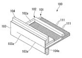
一般的にこのインクジェットヘッドは、図12及び図13に示すように、アクチュエータプレート101、カバープレート102、ノズルプレート103及び支持プレート104で構成されるヘッドチップ100を備えている。
In general, the inkjet head includes a
アクチュエータプレート101は、圧電材料で形成されたプレートであり、側壁110でそれぞれ区切られた複数の溝部111が形成されている。この溝部111は、インクが流れ込んで溜まるチャネルとして機能するものである。これら各溝部111の両側壁110には、それぞれ長手方向に沿って板状の図示しない駆動電極が蒸着等によって形成されている。この駆動電極には、駆動電圧が印加されるようになっている。
The
カバープレート102は、アクチュエータプレート101の上面に重ね合わされており、複数の溝部111を遮蔽している。このカバープレート102には、インクが導入されるインク導入孔102aが凹み形成されている。これにより、複数の溝部111内にインクが導入される。
The
互いに重ね合わされたアクチュエータプレート101及びカバープレート102は、支持プレート104の嵌合孔104aに嵌った状態で支持されている。この際、支持プレート104の端面と、アクチュエータプレート101及びカバープレート102の端面とは、面一な状態とされている。
ノズルプレート103は、板状に形成されたプレートであり、支持プレート104、アクチュエータプレート101及びカバープレート102の端面に接着剤Sを利用して固定されている。なお、図12及び図13では、接着剤Sの図示を省略している。
The
The
ノズルプレート103には、複数のノズル孔103aが一定の間隔を空けた状態で形成されている。この際、複数のノズル孔103aは、複数の溝部111にそれぞれ連通するように形成されている。つまり、ノズル孔103aは、溝部111のピッチと同じ間隔を空けた状態で形成されている。
また、各ノズル孔103aは、溝部111側の入口径の直径が被記録媒体側の出口径の直径よりも大きい断面テーパ状に形成されているのが一般的である。
In the
Further, each
このように構成されたヘッドチップ100を有するインクジェットヘッドにより、インクを吐出させる場合には、まず、インク導入孔102aを介して、複数の溝部111内にインクを供給して充填しておく。そして、駆動電極に対して駆動電圧を印加する。すると、圧電厚み滑り効果により、アクチュエータプレート101の側壁110が変形する。この側壁110の変形及び駆動方法について、より詳細に説明すると、まず、インクを吐出する溝部111の両側の側壁110を、吐出する溝部111に隣接している溝部111側に突出するように変形させる。即ち、吐出する溝部111があたかも膨らむように変形させる。すると、吐出する溝部111の容積が増大するので、インクはインク導入孔102aから溝部111内に誘導される。そして、吐出する溝部111にインクを誘導した後、駆動電極に印加した駆動電圧をゼロにする。これにより、一旦増大した溝部111の容積が元の容積に戻る。この動作によって、吐出する溝部111の内部の圧力が増加し、インクが加圧される。その結果、ノズル孔103aから液滴状のインク、即ちインク滴を吐出させることができる。
When ink is ejected by the ink jet head having the
ところで、さらなる小型化や高画質化を図るために、溝部111の間隔(ピッチ)を狭くする狭ピッチ化が今後のヘッドチップに求められている。具体的には現行、溝部111の横幅が70〜80μm、側壁110の横幅が60μm〜70μm程度に設計されているものを、溝部111の横幅を40μm程度、側壁110の横幅を30μm程度まで狭く設計し、狭ピッチ化を図ることが望まれている。
なお、ノズル孔103aのサイズに関しては、現行、入口径の直径が50μm〜55μm、出口径の直径が20μm〜40μmに形成されているが、狭ピッチ化を図ったとしてもインクの吐出性能を確保するため、これ以上サイズを小さくすることが難しい。そのため、図14に示すように、狭ピッチ化を図った場合には、ノズル孔103aの入口径が溝部111の横幅よりも大きくなってしまうものであった。
By the way, in order to achieve further miniaturization and higher image quality, a future head chip is required to have a narrow pitch that narrows the interval (pitch) of the
Regarding the size of the
ここで、従来のヘッドチップにおいて狭ピッチ化を図った場合には、下記の不都合があった。
通常ヘッドチップ100を組み立てる際、支持プレート104、アクチュエータプレート101及びカバープレート102側に接着剤Sを塗布した状態で、ノズルプレート103を貼り付けている。そのため、この貼り付けの際に、ノズル孔103a内に接着剤Sが流れ込んでしまい、ノズル孔103aの一部を塞いでしまう不都合があった。
特に、上述したようにノズル孔103aの入口径の直径が溝部111の横幅よりも大きいので、図15及び図16に示すように、接着剤Sがノズル孔103a内に流れ込み易く、ノズル孔103aを塞いでしまう確率が高かった。
Here, when the pitch is narrowed in the conventional head chip, there are the following disadvantages.
Normally, when the
In particular, since the diameter of the inlet diameter of the
このように接着剤Sの流れ込みによりノズル孔103aの一部が塞がれてしまうと、インクを正常に吐出することができない等の吐出不良を招いてしまう。そのため、このような不都合が生じないように、何らかの対策を施すことが望まれている。
As described above, when a part of the
そこで、この種の対策の1つとして、ノズルプレートを接着する接着剤に段差加工を施す方法が知られている(特許文献1参照)。この方法は、まず、接着面に予め接着剤が塗布されたノズルプレートにノズル孔を形成する。次に、ノズル孔の周りの接着剤をノズル孔の直径よりも大きい径で同心円状に除去する方法である。 Therefore, as one of the countermeasures of this type, a method is known in which a step process is applied to the adhesive that bonds the nozzle plate (see Patent Document 1). In this method, first, nozzle holes are formed in a nozzle plate in which an adhesive is previously applied to an adhesive surface. Next, the adhesive around the nozzle hole is removed concentrically with a diameter larger than the diameter of the nozzle hole.
また、別の対策の1つとして、ノズルプレートにノズル孔を形成する際に、接着剤の余剰分を補足するための溝をノズル孔の周辺に複数形成する方法が知られている(特許文献2参照)。
しかしながら、従来の方法では、まだ下記の不都合が残されていた。
まず、接着剤に段差加工を施す方法によれば、ノズル孔内への接着剤の流れ込みを防ぐことができると考えられるが、このような方法に最適な接着剤を見出すことが難しい。即ち、この場合の接着剤としては、ノズルプレートを強固に接着する接着性と、段差加工を施すための定形性と、インクに対する耐性とを少なくとも有しているものを使用する必要がある。しかしながら、このような各種の特性を兼ねる接着剤を実際に見出すことは困難であり、実現性に乏しいものであった。
However, the conventional methods still have the following disadvantages.
First, it is considered that the method of applying a step process to the adhesive can prevent the adhesive from flowing into the nozzle hole, but it is difficult to find an optimal adhesive for such a method. That is, as the adhesive in this case, it is necessary to use an adhesive having at least adhesiveness for firmly bonding the nozzle plate, regularity for performing step processing, and resistance to ink. However, it has been difficult to actually find an adhesive having such various properties, and the feasibility is poor.
一方、ノズル孔の周辺に接着剤の余剰分を補足するための溝を複数形成する方法によれば、確かに余った接着剤を溝に引き込むことができるが、ノズル孔に近い位置に塗布されている接着剤に関しては依然としてノズル孔内に流れ込んでしまう。また、溝が余剰な接着剤によって埋まってしまい、それ以上の余剰な接着剤を補足することができなくなってしまった場合には、余剰な接着剤が依然としてノズル孔内に流れ込んでしまう。そのため、流れ込む量を減らすことができるかもしれないが、流れ込み自体を防ぐことができるものではなかった。従って、吐出不良を引き起こす可能性が依然として残るものであった。 On the other hand, according to the method of forming a plurality of grooves for supplementing excess adhesive around the nozzle hole, the excess adhesive can surely be drawn into the groove, but it is applied at a position close to the nozzle hole. The adhesive that is still flowing into the nozzle hole. In addition, when the groove is filled with excess adhesive and no more excess adhesive can be captured, the excess adhesive still flows into the nozzle holes. Therefore, it may be possible to reduce the amount of flow, but the flow itself has not been prevented. Therefore, there is still a possibility of causing ejection failure.
また、余剰な接着剤を含まないようにするという目的のもと、接着するのに十分である接着剤の分量よりも少ない接着剤を塗布することによって、ノズルプレート103と、アクチュエータプレート101及びカバープレート102からなる接合体とを接着する手法も考えられる。しかしながら、このような手法を採用した場合、接着が不十分である可能性がある。しかしながら、接着が不十分である場合には、以下の不都合が懸念される。
例えば、接着が不十分な場合には、ノズルプレート103を図示しないワイパー等の清掃部材によって清掃をしたときに、ノズルプレート103が上述した接合体から剥がれてしまう恐れがある。更に、接着が不十分な場合には、ノズルプレート103と接合体との間に不要な隙間が形成される恐れがあり、吐出する溝部111に誘導したインクが隙間から漏れ出てしまう恐れがある。
このように、接着材が不十分な場合には、上述した不都合が生じてしまう可能性が考えられるので、十分な分量の接着剤を塗布することが必要不可欠であり、ノズルプレート103と接合体とを確実に接着する必要がある。従って、接着剤に起因する上述した問題が生じてしまうものであった。
In addition, for the purpose of not including excessive adhesive, the
For example, when the adhesion is insufficient, when the
As described above, if the adhesive is insufficient, the above-described disadvantage may occur. Therefore, it is indispensable to apply a sufficient amount of the adhesive, and the
本発明は、このような事情に考慮してなされたもので、その目的は、狭ピッチ化を図ることができると共に、簡単な構成でノズル孔内への接着剤の流れ込みを効果的に防止して吐出不良を招くことがない高品質なヘッドチップ、液体噴射ヘッド及び液体噴射装置を提供することである。 The present invention has been made in view of such circumstances, and the object thereof is to reduce the pitch and to effectively prevent the adhesive from flowing into the nozzle hole with a simple configuration. Another object of the present invention is to provide a high-quality head chip, liquid ejecting head, and liquid ejecting apparatus that do not cause ejection failure.
本発明は、前記課題を解決するために以下の手段を提供する。
本発明に係るヘッドチップは、被記録媒体に向けて液体を吐出するヘッドチップであって、前記液体が充填される複数の溝部が横幅方向に一定間隔を空けた状態で形成されたアクチュエータプレートと、前記溝部の側壁にそれぞれ形成され、駆動電圧が印加されたときに側壁を変形させることで溝部内の圧力を高め、充填された前記液体を溝部内から吐出させる駆動電極と、前記アクチュエータプレートに重ねられ、前記複数の溝部に前記液体を導入させる導入孔が形成されたカバープレートと、前記アクチュエータプレートの端面に接着剤を介して固定され、前記横幅方向に前記複数の溝部と同じ間隔で複数のノズル孔が形成されたノズルプレートと、を備え、前記ノズルプレートと前記アクチュエータプレートとの間には、前記ノズル孔と前記溝部とをそれぞれ連通する逃げ孔がノズル孔の数に対応して形成され、該逃げ孔の外形輪郭線がノズル孔の外形輪郭線から少なくとも一定距離以上離間した状態でノズル孔の周囲を囲むと共に、該逃げ孔にはノズルプレートの固定時に余った前記接着剤が溜め込まれ、前記複数のノズル孔及び逃げ孔が、隣り合うノズル孔及び逃げ孔に対して、前記横幅方向に直交する前記ノズルプレートの縦幅方向に所定距離だけずれた状態で配列されていることを特徴とする。
The present invention provides the following means in order to solve the above problems.
A head chip according to the present invention is a head chip that discharges liquid toward a recording medium, and an actuator plate that is formed with a plurality of grooves filled with the liquid spaced apart from each other in a horizontal width direction. A drive electrode that is formed on each side wall of the groove and deforms the side wall when a drive voltage is applied, thereby increasing the pressure in the groove and discharging the filled liquid from the inside of the groove; and the actuator plate A cover plate which is overlapped and formed with an introduction hole for introducing the liquid into the plurality of grooves, and is fixed to an end surface of the actuator plate via an adhesive, and a plurality of grooves are arranged at the same interval as the plurality of grooves in the lateral width direction. A nozzle plate having a nozzle hole formed between the nozzle plate and the actuator plate. Relief holes communicating with the groove portions are formed corresponding to the number of nozzle holes, and the outer contour lines of the relief holes surround the nozzle holes in a state of being separated from the outer contour lines of the nozzle holes by at least a predetermined distance. In addition, the surplus adhesive is accumulated in the escape hole when the nozzle plate is fixed, and the plurality of nozzle holes and escape holes are perpendicular to the lateral width direction with respect to the adjacent nozzle holes and escape holes. The plates are arranged in a state shifted by a predetermined distance in the vertical width direction of the plate.
この発明に係るヘッドチップにおいては、カバープレートに形成された導入孔を介して、アクチュエータプレートに形成された複数の溝部内に液体が充填されている。ここで、駆動電極に駆動電圧を印加すると、圧電厚み滑り効果により溝部の側壁が変形する。これにより、溝部内の容積が減少して圧力が高まり、充填された液体が溝部内から吐出される。すると、吐出された液体は、逃げ孔によって連通されているノズル孔を通過した後、外部に吐出される。しかも、ノズル孔を通過する際に、液体は液滴状、即ち液滴となって吐出される。その結果、被記録媒体に文字や画像等を記録することができる。 In the head chip according to the present invention, the liquid is filled in the plurality of grooves formed in the actuator plate through the introduction holes formed in the cover plate. Here, when a drive voltage is applied to the drive electrode, the side wall of the groove is deformed by the piezoelectric thickness slip effect. As a result, the volume in the groove is reduced, the pressure is increased, and the filled liquid is discharged from the groove. Then, the discharged liquid passes through the nozzle hole communicated by the escape hole and is then discharged to the outside. Moreover, when passing through the nozzle hole, the liquid is ejected in the form of droplets, that is, droplets. As a result, characters, images, etc. can be recorded on the recording medium.
ところで、ヘッドチップを組み立てるにあたり、アクチュエータプレートの端面に接着剤を介してノズルプレートを固定する必要がある。この際、ノズルプレートとアクチュエータプレートとの間には、余った接着剤が逃げ込んで溜め込まれる逃げ孔がノズル孔の数に対応して設けられている。しかも、これら逃げ孔は、外形輪郭線がノズル孔の外形輪郭線から少なくとも一定距離以上離間した状態でノズル孔の周囲を囲むように形成されている。 By the way, when assembling the head chip, it is necessary to fix the nozzle plate to the end face of the actuator plate via an adhesive. At this time, relief holes corresponding to the number of nozzle holes are provided between the nozzle plate and the actuator plate to allow excess adhesive to escape and accumulate. Moreover, these escape holes are formed so as to surround the periphery of the nozzle hole in a state where the outer contour line is at least a predetermined distance away from the outer contour line of the nozzle hole.
従って、ノズルプレートの接着時に、余った接着剤が拡がったとしてもノズル孔に到達する前に逃げ孔に入り込ませて溜め込むことができる。そのため、ノズル孔内に接着剤が流れ込んで該ノズル孔を塞いでしまうことがないので、吐出不良を防止することができる。特に、逃げ孔は、ノズル孔がどのような形状であったとしても外形輪郭線から少なくとも一定距離以上離間するように外形形成されているので、逃げ込んできた接着剤を確実に溜め込むことができる。よって、吐出不良を効果的に防止することができる。
これらのことから、吐出不良を招くことがない高品質なヘッドチップとすることができる。また、逃げ孔を設けるだけの簡単な構成であるので、容易にヘッドチップを組み立てることができ、歩留まりを向上して低コスト化を図ることもできる。また、実現性の高いヘッドチップとすることができる。
Therefore, even when the excess adhesive spreads when the nozzle plate is bonded, it can enter and accumulate in the escape hole before reaching the nozzle hole. For this reason, the adhesive does not flow into the nozzle hole and block the nozzle hole, so that ejection failure can be prevented. In particular, the escape hole is formed so as to be at least a predetermined distance away from the outer contour line regardless of the shape of the nozzle hole, so that the escaped adhesive can be reliably stored. Therefore, ejection failure can be effectively prevented.
From these things, it can be set as the high quality head chip which does not cause discharge defect. In addition, since it is a simple configuration in which only a relief hole is provided, the head chip can be assembled easily, and the yield can be improved and the cost can be reduced. Also, a highly feasible head chip can be obtained.
更に、複数のノズル孔及び逃げ孔は、横幅方向に向けて一直線に並んでいるのではなく、隣り合うノズル孔及び逃げ孔に対して、ノズルプレートの縦幅方向に所定距離だけずれた状態で配列されている。つまり、隣接するノズル孔及び逃げ孔同士は、横に並ぶことがないので、周囲にある程度自由なスペースが確保されている。そのため、溝部の横幅や側壁の横幅を従来よりも短くして狭ピッチ化を図ったとしても、ノズル孔のサイズを小さくする必要がなく従来と同じ大きさのままにすることができる。しかも、逃げ孔の存在により、ノズル孔内に接着剤が流れ込む恐れもない。これらのことから、ヘッドチップの狭ピッチ化を図ることができる。 Further, the plurality of nozzle holes and escape holes are not aligned in a straight line in the lateral width direction, but are shifted by a predetermined distance in the longitudinal width direction of the nozzle plate with respect to the adjacent nozzle holes and escape holes. It is arranged. That is, since the adjacent nozzle holes and escape holes are not arranged side by side, a certain amount of free space is secured around the periphery. Therefore, even if the lateral width of the groove and the lateral width of the side wall are made shorter than before and the pitch is narrowed, it is not necessary to reduce the size of the nozzle holes and the same size as before can be maintained. In addition, the presence of the escape hole prevents the adhesive from flowing into the nozzle hole. For these reasons, the pitch of the head chips can be reduced.
また、本発明に係るヘッドチップは、上記本発明に係るヘッドチップにおいて、前記複数のノズル孔及び逃げ孔が、前記所定距離だけ間を空けて平行に2列に並ぶように、前記横幅方向に向けて千鳥状に配列されていることを特徴とする。 The head chip according to the present invention is the head chip according to the present invention described above, wherein the plurality of nozzle holes and the escape holes are arranged in the horizontal direction so that the nozzle holes and the escape holes are arranged in two rows in parallel with the predetermined distance therebetween. It is characterized by being arranged in a staggered pattern.
この発明に係るヘッドチップにおいては、複数のノズル孔及び逃げ孔が横幅方向に向けて交互に千鳥状に配列されており、横幅方向に直交する縦幅方向に所定距離だけ間を空けて平行に2列に並んでいる。特に、ノズル孔の位置がバラバラではなく、2列に統制されているので、液体を吐出する際の制御がより簡便になる。 In the head chip according to the present invention, the plurality of nozzle holes and escape holes are alternately arranged in a staggered pattern in the horizontal width direction, and are parallel to each other with a predetermined distance in the vertical width direction orthogonal to the horizontal width direction. It is lined up in two rows. In particular, since the positions of the nozzle holes are not scattered and are regulated in two rows, the control when ejecting the liquid becomes simpler.
また、本発明に係るヘッドチップは、上記本発明のヘッドチップにおいて、前記ノズル孔が、前記外形輪郭線が円形を描くように形成された孔であることを特徴とする。 Moreover, the head chip according to the present invention is characterized in that, in the head chip of the present invention, the nozzle hole is a hole formed so that the outer contour line draws a circle.
この発明に係るヘッドチップにおいては、ノズル孔が円形に形成されているので、液体をより真っ直ぐに直進性を向上させた状態で吐出することができる。従って、ヘッドチップの品質をより高めることができる。 In the head chip according to the present invention, since the nozzle hole is formed in a circular shape, the liquid can be discharged in a state where straightness is improved more straightly. Therefore, the quality of the head chip can be further improved.
また、本発明に係るヘッドチップは、上記本発明のヘッドチップにおいて、前記逃げ孔が、中心が前記ノズル孔の中心に略一致した正方形状に形成されていることを特徴とする。 The head chip according to the present invention is characterized in that, in the head chip of the present invention, the escape hole is formed in a square shape whose center substantially coincides with the center of the nozzle hole.
この発明に係るヘッドチップにおいては、逃げ孔が複雑な形状ではなく単純な正方形状であるので、逃げ孔を簡便に設けることができる。また、正方形状の逃げ孔であるので、ノズル孔が円形である場合には、逃げ孔の四隅に接着剤を溜め込むことができるスペースをより多く確保することができる。従って、接着剤がノズル孔側に流れてしまうことをより確実に防止することができる。 In the head chip according to the present invention, since the escape hole is not a complicated shape but a simple square shape, the escape hole can be easily provided. Moreover, since it is a square-shaped escape hole, when the nozzle hole is circular, more space can be secured in which the adhesive can be stored in the four corners of the escape hole. Therefore, it can prevent more reliably that an adhesive agent flows into the nozzle hole side.
また、本発明に係るヘッドチップは、上記本発明のヘッドチップにおいて、前記逃げ孔が、前記ノズルプレートと前記アクチュエータプレートとの間に介在され、両プレートに対して前記接着剤を介して固定される接着プレートに形成されていることを特徴とする。 The head chip according to the present invention is the head chip according to the present invention, wherein the escape hole is interposed between the nozzle plate and the actuator plate, and is fixed to both plates via the adhesive. It is characterized by being formed on the adhesive plate.
この発明に係るヘッドチップにおいては、接着プレートに逃げ孔を形成できるので、所望の大きさ及び形状の逃げ孔を確実に得ることができる。特に、接着プレートを介在させるだけで、複数のノズル孔に対して逃げ孔を容易且つ確実に位置合わせできるので、組み立てがより簡便になる。 In the head chip according to the present invention, since the escape hole can be formed in the adhesive plate, the escape hole having a desired size and shape can be obtained with certainty. In particular, the escape holes can be easily and reliably positioned with respect to the plurality of nozzle holes only by interposing the adhesive plate, so that the assembly becomes simpler.
また、本発明に係るヘッドチップは、上記本発明のヘッドチップにおいて、前記複数の溝部が、前記液体が充填される吐出チャネルとして機能する部分と、液体が非充填されるダミーチャネルとして機能する部分とが交互に並ぶように設けられ、前記導入孔には、前記吐出チャネルとして機能する溝部にだけ前記液体を導入するスリットが形成され、前記ノズル孔が、前記吐出チャネルとして機能する溝部にだけ連通するように形成されていることを特徴とする。 In the head chip according to the present invention, in the head chip according to the present invention, the plurality of groove portions function as a discharge channel filled with the liquid and a function as a dummy channel not filled with the liquid. And the introduction hole is formed with a slit for introducing the liquid only in the groove functioning as the discharge channel, and the nozzle hole communicates only with the groove functioning as the discharge channel. It is formed so that it may do.
この発明に係るヘッドチップにおいては、導入孔にスリットが形成されているので、複数の溝部のうち、吐出チャネルとして機能する溝部だけに液体を導入することができる。つまり、ダミーチャネルとして機能する溝部を間に1つ空けて、吐出チャネルとして機能する溝部だけに液体を導入することができる。そして、駆動電極に電圧を印加すると、吐出チャネルとして機能する溝部に充填された液体を、ノズル孔を介して吐出することができる。
特に、複数の溝部が1つおきに吐出チャネルとして機能するので、導電性を有する液体を用いたとしても、吐出チャネルとして機能する溝部の側壁に形成された駆動電極と、ダミーチャネルとして機能する溝部の側壁に形成された駆動電極とを、液体を介して導通させることなく電気的に切り離した状態で使い分けることができる。従って、導電性の液体を利用して記録を確実に行うことができる。加えて、利用できる液体の選択幅が広がるので、付加価値を高めることができる。
In the head chip according to the present invention, since the slit is formed in the introduction hole, the liquid can be introduced only into the groove functioning as the ejection channel among the plurality of grooves. That is, it is possible to introduce a liquid only into the groove portion functioning as the discharge channel, with one groove portion functioning as the dummy channel interposed therebetween. When a voltage is applied to the drive electrode, the liquid filled in the groove functioning as an ejection channel can be ejected through the nozzle hole.
In particular, since every other groove functions as an ejection channel, even if a conductive liquid is used, the drive electrode formed on the sidewall of the groove functioning as the ejection channel and the groove functioning as a dummy channel The drive electrode formed on the side wall can be properly used in a state where it is electrically disconnected without being conducted through the liquid. Therefore, recording can be reliably performed using the conductive liquid. In addition, since the range of available liquids can be expanded, the added value can be increased.
また、本発明に係る液体噴射ヘッドは、上記本発明のヘッドチップと、所定量の前記液体を前記導入孔に供給する供給手段と、前記駆動電極に前記駆動電圧を印加する制御手段と、を備えていることを特徴とする。 The liquid jet head according to the present invention includes the head chip according to the present invention, a supply unit that supplies a predetermined amount of the liquid to the introduction hole, and a control unit that applies the drive voltage to the drive electrode. It is characterized by having.
この発明に係る液体噴射ヘッドにおいては、供給手段がヘッドチップの導入孔に対して所定量の液体を確実に供給している。そして、制御手段により駆動電極に駆動電圧を適宜印加することで、上述したように液体をノズル孔から吐出して記録を行うことができる。
特に、吐出不良を招くことのない高品質なヘッドチップを備えているので、記録を確実に行うことができ、同様に高品質化を図ることができる。また、狭ピッチ化されたヘッドチップでもあるので、高画質に記録を行うことができると共に小型化を図ることもできる。
In the liquid jet head according to the present invention, the supply means reliably supplies a predetermined amount of liquid to the introduction hole of the head chip. Then, by appropriately applying a driving voltage to the driving electrode by the control means, it is possible to perform recording by discharging the liquid from the nozzle hole as described above.
In particular, since a high-quality head chip that does not cause ejection failure is provided, recording can be performed reliably and high quality can be achieved as well. In addition, since the head chip has a narrow pitch, it is possible to perform recording with high image quality and miniaturization.
また、本発明に係る液体噴射装置は、上記本発明の液体噴射ヘッドと、前記被記録媒体を予め決められた方向に搬送する搬送手段と、前記被記録媒体の搬送方向に直交する方向に前記液体噴射ヘッドを往復移動させる移動手段と、を備えていることを特徴とする。 The liquid ejecting apparatus according to the present invention includes the liquid ejecting head according to the present invention, a transport unit that transports the recording medium in a predetermined direction, and a direction orthogonal to a transport direction of the recording medium. Moving means for reciprocating the liquid ejecting head.
この発明に係る液体噴射装置においては、搬送手段が被記録媒体を予め決められた方向に搬送しながら、移動手段が被記録媒体の搬送方向に直交する方向に液体噴射ヘッドを往復移動させる。これにより、被記録媒体の所望する範囲に対して正確に記録を行うことができる。特に、吐出不良を招くことがない高品質な液体噴射ヘッドを備えているので、やはり同様に液体噴射装置自体の高品質化を図ることができる。 In the liquid ejecting apparatus according to the present invention, the transport unit reciprocates the liquid ejecting head in a direction orthogonal to the transport direction of the recording medium while the transport unit transports the recording medium in a predetermined direction. Thereby, it is possible to perform recording accurately in a desired range of the recording medium. In particular, since the high-quality liquid ejecting head that does not cause ejection failure is provided, the quality of the liquid ejecting apparatus itself can be improved as well.
本発明に係るヘッドチップによれば、狭ピッチ化を図ることができるうえ、簡単な構成でノズル孔内への接着剤の流れ込みを効果的に防止することができ、吐出不良を招くことのない高品質なヘッドチップとすることができる。
また、本発明に係る液体噴射ヘッド及び液体噴射装置によれば、上記ヘッドチップを備えているので、接着剤の流れ込みに起因する吐出不良をなくすことができ、高品質化を図ることができる。狭ピッチ化が図られたヘッドチップを備えているので、高画質化や小型化を図ることができる。
According to the head chip of the present invention, it is possible to reduce the pitch, and to effectively prevent the adhesive from flowing into the nozzle hole with a simple configuration without causing a discharge failure. High quality head chips can be obtained.
In addition, according to the liquid ejecting head and the liquid ejecting apparatus according to the invention, since the head chip is provided, it is possible to eliminate a discharge failure due to the flow of the adhesive and to improve the quality. Since the head chip with a narrow pitch is provided, high image quality and miniaturization can be achieved.
以下、本発明に係る一実施形態を、図1から図11を参照して説明する。
なお、本実施形態では、液体噴射装置の一例として、非導電性の非水性のインク(液体)Wを利用して記録を行うインクジェットプリンタ1を例に挙げて説明する。
Hereinafter, an embodiment according to the present invention will be described with reference to FIGS. 1 to 11.
In the present embodiment, as an example of the liquid ejecting apparatus, an
本実施形態のインクジェットプリンタ1は、図1に示すように、インクWを吐出する複数のインクジェットヘッド(液体噴射ヘッド)2と、記録紙(被記録媒体)Pを予め決められた搬送方向L1に搬送する搬送手段3と、この搬送方向L1に直交する直交方向L2に複数のインクジェットヘッド2を往復移動させる移動手段4とを、備えている。
As shown in FIG. 1, the
つまり、このインクジェットプリンタ1は、記録紙Pを搬送方向L1に搬送しながら、該搬送方向L1に直交する直交方向L2にインクジェットヘッド2を移動させて、記録紙Pに文字や画像を記録する所謂シャトルタイプのプリンタである。
なお、本実施形態では、それぞれ異なる色(例えば、ブラック、シアン、マゼンタ及びイエロー)のインクWを吐出する4つのインクジェットヘッド2を備えている場合を例にしている。なお、これら4つのインクジェットヘッド2は、同一構成とされている。
That is, the
In the present embodiment, an example in which four
これら4つのインクジェットヘッド2は、略直方体形状の筐体5内に組み込まれたキャリッジ6に搭載されている。
このキャリッジ6は、複数のインクジェットヘッド2を載置する平板状の基台6aと、該基台6aから垂直に立ち上げられた壁部6bと、で構成されており、直交方向L2に沿って配置されたガイドレール7によって往復移動可能に支持されている。また、キャリッジ6は、ガイドレール7に支持された状態で一対のプーリ8に巻回された搬送ベルト9に連結されている。一対のプーリ8のうち一方のプーリ8は、モータ10の出力軸に連結されており、モータ10からの回転駆動力を受けて回転するようになっている。これにより、キャリッジ6は、直交方向L2に向けて往復移動できるようになっている。
即ち、これら一対のガイドレール7、一対のプーリ8、搬送ベルト9及びモータ10は、上記移動手段4として機能する。
These four
The carriage 6 includes a
That is, the pair of
また、筐体5には、一対のガイドレール7と同じ直交方向L2に沿って一対の搬入ローラ15と、一対の搬送ローラ16とが間隔を空けて並設されている。一対の搬入ローラ15は、筐体5の背面側に設けられ、一対の搬送ローラ16は筐体5の前面側に設けられている。そして、これら一対の搬入ローラ15及び一対の搬送ローラ16は、図示しないモータによって記録紙Pを間に挟んだ状態で回転するようになっている。これにより、筐体5の背面側から前面側に向かう搬送方向L1に沿って記録紙Pを搬送することができるようになっている。
即ち、これら一対の搬入ローラ15及び一対の搬送ローラ16は、上記搬送手段3として機能する。
In addition, a pair of carry-in
That is, the pair of carry-in
各インクジェットヘッド2は、図2に示すように、キャリッジ6の基台6aに図示しないネジを介して取り付けられる矩形状の固定板20と、該固定板20の上面に固定されたヘッドチップ21と、該ヘッドチップ21の後述するインク導入孔31aにインクWを供給する供給手段22と、後述する駆動電極37に駆動電圧を印加する制御手段23と、を主に備えている。
As shown in FIG. 2, each
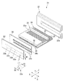
ヘッドチップ21は、図3及び図4に示すように、アクチュエータプレート30、カバープレート31、支持プレート32、ノズルプレート33及び接着プレート34とで主に構成されている。
アクチュエータプレート30は、PZT(チタン酸ジルコン酸鉛)等の圧電材料から形成されたプレートである。このアクチュエータプレート30の上面には、長さ方向(矢印X方向)に伸びる溝部35が横幅方向(矢印Y方向)に一定間隔を空けた状態で複数形成されている。即ち、複数の溝部35は、側壁36によってそれぞれ区分けされた状態となっている。
As shown in FIGS. 3 and 4, the
The
複数の溝部35は、アクチュエータプレート30の前端面側に開口するように形成されていると共に、後端面に向かうにしたがって漸次深さが浅くなるように形成されている。なお、溝部35の後端面側は、図示しない封止手段によって封止されている。これら複数の溝部は、インクWが充填されるチャネルとして機能する。
The plurality of
複数の溝部35の側壁36には、図5及び図6に示すように、長さ方向に亘って駆動電極37が蒸着等により形成されている。この駆動電極37は、各溝部35内において深さが浅くなるアクチュエータプレート30の後端面側で電気的に1つに合流した状態となっている。そして、後述するフレキシブル基板27の引き出し電極27aに電気的に接続されるようになっている。
そして、駆動電極37は、駆動電圧が印加されたときに、側壁36を圧電厚み滑り効果により変形させることで溝部内の圧力を高め、充填されたインクWを溝部内から吐出させる働きをしている。
As shown in FIGS. 5 and 6, drive
The
図3及び図4に戻って、カバープレート31は、複数の溝部35の一部を露出させた状態で、アクチュエータプレート30の上面に重ね合わされている。また、カバープレート31には、インクWが供給されてくるインク導入孔31aが横幅方向に亘って形成されている。これより、複数の溝部35にインクWを充填できるようになっている。
Returning to FIGS. 3 and 4, the
支持プレート32は、重ね合わされたアクチュエータプレート30及びカバープレート31を支持していると共に、ノズルプレート33及び接着プレート34を同時に支持している。支持プレート32には、横幅方向に亘って嵌合孔32aが形成されており、重ね合わされたアクチュエータプレート30及びカバープレート31をこの嵌合孔32a内に嵌め込んだ状態で両プレート30、31を支持している。この際、支持プレート32の端面は、両プレート30、31の前端面と面一となるように組み合わされている。
The
そして、これら支持プレート32の端面、両プレート30、31の前端面に、接着プレート34を間に介在させた状態でノズルプレート33が接着剤Sにより接着固定されている。なお、図3及び図4では、接着剤Sの図示を省略している。
このノズルプレート33は、厚みが50μm程度のポリイミド等のフィルム材からなるシート状のプレートである。そして、ノズルプレート33は、一方の面が接着プレート34に接着される接着面となっており、他方の面が記録紙Pに対向する対向面となっている。なお、対向面には、インクWの付着等を防止するための撥水性を有する撥水膜がコーティングされている。
The
The
また、このノズルプレート33には、横幅方向に複数の溝部35のピッチと同じ間隔で複数のノズル孔33aが形成されている。この際、ノズル孔33aは、隣り合うノズル孔33aに対して横幅方向に直交するノズルプレートの縦幅方向(矢印Z方向)に所定距離N1だけずれた状態で配列されるように形成されている。
より具体的に説明すると、複数のノズル孔33aは、横幅方向に向けて交互に千鳥状に配列されるように形成されており、縦幅方向に所定距離N1だけ間を空けて平行に2列に並んだ状態となっている。しかも、各ノズル孔33aは、図7及び図8に示すように、各溝部35の横幅中心線上に中心が位置するように形成されている。
加えて、本実施形態では、上記所定距離N1が溝部の縦幅N2よりも大きく長く設計されており、ノズルプレート33を平面視したときにノズル孔33aと溝部35とが直線上に重ならないようになっている。
In addition, a plurality of nozzle holes 33 a are formed in the
More specifically, the plurality of
In addition, in the present embodiment, the predetermined distance N1 is designed to be longer than the vertical width N2 of the groove, so that the
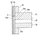
また、各ノズル孔33aは、外形輪郭線が円形を描くように円状に形成されている。しかも、図4に示すように、接着面側の入口径D1(ノズル孔33aの外形輪郭線の直径)が対向面側の出口径D2よりも大きい断面テーパ状に形成されている。特に、ノズル孔33aの入口径D1の直径は、溝部35の横幅よりも大きいサイズとされている。
なお、ノズル孔33aは、エキシマレーザ装置等を用いて形成されている。
Moreover, each
The
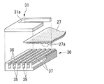
接着プレート34は、図3及び図4に示すように、ノズルプレート33と略同じ厚みで同じサイズに形成されたプレートである。なお、材質としては、例えばセラミックやポリイミド等であるが、インクWに耐性を有していれば自由に選択して構わない。また、接着プレート34の材質は、アクチュエータプレート30及びカバープレート31の接合体と接着するため、相互の熱変形が略同等となるように接合体に使用する材質と略同等の熱変形特性を備えていることが好ましい。
As shown in FIGS. 3 and 4, the
この接着プレート34には、複数のノズル孔33aにそれぞれ対向するように形成されている。即ち、横幅方向に向けてノズル孔33aと同じピッチで千鳥状に複数形成されている。しかも、逃げ孔34aは、図8に示すように、外形輪郭線がノズル孔33aの外形輪郭線から少なくとも一定距離H離間した状態でノズル孔33aの周囲を囲むように形成されており、ノズルプレート33の固定時に余った接着剤Sが逃げ込んで溜め込まれるようになっている。
The
具体的に逃げ孔34aは、中心がノズル孔33aの中心に一致した正方形状に形成されており、一辺の長さが〔(ノズル孔33aの入口径の直径D1)+((上記一定距離H)×2)〕となっている。しかも、この逃げ孔34aには、溝部35に向けて延出した延出部34bが一部に形成されており、図8及び図9に示すように、ノズル孔33aと溝部35とをそれぞれ連通させている。これにより、溝部35にて加圧されたインクWを、逃げ孔34aを介してノズル孔33aから外部に吐出できるようになっている。
Specifically, the
図2に示すように、このように構成されたヘッドチップ21は、上述したように固定板20の上面に固定されている。この固定板20の上面には、アルミニウム等で形成された矩形状のベースプレート24が垂直に立ち上がった状態で固定されていると共に、ヘッドチップ21のインク導入孔31aにインクWを供給する流路部材22aが固定されている。この流路部材22aの上方には、インクWを貯留する貯留室を内部に有する圧力緩衝器22bがベースプレート24に支持された状態で配置されている。この圧力緩衝器22bと流路部材22aとは、インク連結管22cを介して連結されている。また、圧力緩衝器22bの上部には、インクWが供給されてくる供給チューブ40が取り付けられている。
このように構成されているので、供給チューブ40を介して圧力緩衝器22bにインクWが供給されると、該インクWは圧力緩衝器22b内の貯留室に一旦貯留される。そして、圧力緩衝器22bは、貯留されたインクWのうち、所定量のインクWをインク連結管22c及び流路部材22aを介してヘッドチップ21のインク導入孔31aに供給するようになっている。
即ち、流路部材22a、圧力緩衝器22b及びインク連結管22cは、上記供給手段22として機能する。
As shown in FIG. 2, the
With this configuration, when ink W is supplied to the
That is, the
なお、供給チューブ40は、図1に示すように、筐体5内に組み込まれたインクタンク41に連結されている。これにより、インクタンク41に貯留されている色の異なるインクWが、4つのインクジェットヘッド2にそれぞれ供給されるようになっている。
The
また、図2に示すように、ベースプレート24には、ヘッドチップ21を駆動するための集積回路等の駆動回路25が搭載されたIC基板26が固定されている。この駆動回路25と、ヘッドチップ21の駆動電極37とは、複数の引き出し電極27aがプリント配線されたフレキシブル基板27を介して電気的に接続されている。
フレキシブル基板27は、図5に示すように、深さが浅くなった各溝部35に嵌り込む形で駆動電極37に接続されている。そして、駆動回路25は、フレキシブル基板27を介して駆動電極37に駆動電圧を印加して、インクWの吐出を行わせている。
即ち、駆動回路25及びフレキシブル基板27は、上記制御手段23として機能する。
As shown in FIG. 2, an
As shown in FIG. 5, the
That is, the
次に、上述したように構成されたインクジェットプリンタ1を利用して、記録紙Pに文字や図形等を記録する場合について以下に説明する。
なお、初期状態として、4つのインクタンク41にはそれぞれ異なる色のインクWが十分に封入されているものとする。また、水頭差によって、インクタンク41内のインクWが供給チューブ40を介して圧力緩衝器22bに供給された状態となっている。そのため、所定量のインクWがインク連結管22c及び流路部材22aを介してヘッドチップ21のインク導入孔31aに供給され、複数の溝部35内に充填された状態となっている。
Next, a case where characters, figures, and the like are recorded on the recording paper P using the
As an initial state, it is assumed that the four
このような初期状態のもと、インクジェットプリンタ1を作動させると、一対の搬入ローラ15及び一対の搬送ローラ16が回転して記録紙Pを搬送方向L1に向けて搬送する。また、これと同時にモータ10がプーリ8を回転させて搬送ベルト9を動かす。これにより、キャリッジ6がガイドレール7でガイドされながら直交方向L2に往復移動する。そしてこの間に、各インクジェットヘッド2のヘッドチップ21より4色のインクWを記録紙Pに適宜吐出させることで、文字や画像等の記録を行うことができる。特に、シャトル方式であるので、記録紙Pの所望する範囲に対して正確に記録を行うことができる。
When the
ここで、各インクジェットヘッド2の動きについて、以下に詳細に説明する。
キャリッジ6によって往復移動が開始されると、駆動回路25は、フレキシブル基板27を介して駆動電極37に駆動電圧を印加する。より詳しくは、図10に示すように、インクWを吐出する溝部35の両側の2つの側壁36にそれぞれ設けられている駆動電極37に駆動電圧を印加し、この2つの側壁36を、インクWを吐出させる溝部35に隣接している溝部35側へ突出するように変形させる。即ち、吐出する溝部35があたかも膨らむように変形させる。なお、図10では、1つの溝部35からインクWを吐出する場合を例に挙げて図示している。
Here, the movement of each
When reciprocation is started by the carriage 6, the
この2つの側壁36の圧電厚み滑り効果による変形によって、吐出する溝部35の容積が増大する。そして、溝部35の容積が増大したことにより、インクWがインク導入孔31aから溝部35に誘導される。そして、インクWを溝部35に誘導したタイミングで、駆動電極37に印加した駆動電圧をゼロにする。これにより、側壁36の変形が元に戻り、一旦増大した溝部35の容積が元の容積に戻る。この動作によって、吐出する溝部35の内部の圧力が増加し、インクWが加圧される。その結果、インクWが溝部35内から吐出される。
Due to the deformation due to the piezoelectric thickness sliding effect of the two
なお、ここで述べている駆動電極37は、それぞれ隣接する溝部35から選択的にインクWを吐出させるための電極として、別々に機能するように形成されている。また、インクWを安定して吐出するために、さらなるインクWの加圧が必要な場合には、側壁36を吐出する溝部35側へ突出するように変形させる。この動作によって、吐出する溝部35
の内部の圧力がさらに増加するので、インクWをより加圧することができる。但し、この動作は上述したとおり、インクWを安定して吐出させることを目的とするものであるので、必須な動作ではなく必要に応じて適宜使用すれば良い。
また、本実施形態では、非水性のインクWを使用しているので、上述した各動作を必要に応じて組み合わせて実行することにより、最適なインクWの吐出を実現することができる。
The
Since the pressure inside the ink further increases, the ink W can be further pressurized. However, this operation is aimed at stably ejecting the ink W as described above, and therefore it is not an essential operation and may be used as needed.
Further, in the present embodiment, since the non-aqueous ink W is used, optimal ink ejection can be realized by executing the above-described operations in combination as necessary.
吐出されたインクWは、逃げ孔の延出部34bを介してノズル孔33aを通過した後、外部に吐出される。しかもノズル孔33aを通過する際に、インクWは液滴状、即ちインク滴となって吐出される。その結果、上述したように、記録紙Pに文字や画像等を記録することができる。
特に、本実施形態のノズル孔33aは、断面テーパ状であるので、インク滴を速い速度で真っ直ぐに直進性良く吐出することができる。よって、高画質に記録を行うことができる。
The discharged ink W passes through the
In particular, since the
次に、このように構成されたヘッドチップ21を組み立てるにあたり、ノズルプレート33の固定について簡単に説明する。
まず、固定に先立って、アクチュエータプレート30及びカバープレート31の前端面に接着剤Sを塗布した後、溝部35に接着プレート34の逃げ孔34a及び延出部34bが対向するように位置合わせを行いながら該接着プレート34を両プレート30、31の前端面に接触させ、加熱硬化させる。この際、加熱することで硬化するエポキシ系の接着剤Sを用いることが好ましい。次に、接着プレート34に接着剤Sを塗布した後、今度は逃げ孔34aとノズル孔33aとが対向するように位置合わせを行いながらノズルプレート33を接着プレート34に接触させ、加熱硬化させる。最後に、支持プレート32の端面に接着剤Sを塗布した後、ノズルプレート33の裏面に押し付けて加熱し、硬化させる。これにより、図3に示すヘッドチップ21を組み立てることができる。
Next, in assembling the
First, before fixing, the adhesive S is applied to the front end surfaces of the
特に、ノズルプレート33の接着時に余った接着剤Sが拡がったとしても、図8及び図9に示すように、該接着剤Sをノズル孔33aに到達する前に逃げ孔34aに入り込ませて溜め込むことができる。そのため、ノズル孔33a内に接着剤Sが流れ込んで該ノズル孔33aを防いでしまうことがないので、吐出不良を防止することができる。しかも、逃げ孔34aは、ノズル孔33aの外形輪郭線から少なくとも一定距離H離間する大きさで形成されているので、逃げ込んできた接着剤Sを確実に溜め込むことができる。加えて、本実施形態の逃げ孔34aは正方形状であるので、四隅に接着剤Sを溜め込むことができるスペースが多く確保されている。従って、接着剤Sがノズル孔33a側に流れてしまうことを確実に防止できる。その結果、接着剤Sの流れ込みに起因する吐出不良を効果的に防止することができる。
In particular, even if the surplus adhesive S spreads when the
これらのことから、吐出不良を招くことのない高品質なヘッドチップ21とすることができる。また、逃げ孔34aを設けるだけの簡単な構成であるので、容易にヘッドチップ21を組み立てることができ、歩留まりを向上して低コスト化を図ることができると共に、実現性の高いヘッドチップ21とすることができる。
しかも、複数の逃げ孔34aは接着プレート34に形成されている。よって、接着プレート34とノズルプレート33とを重ね合わせるだけで、複数のノズル孔33aに対して逃げ孔34aを容易且つ確実に位置合わせできるので、組み立てが簡便である。
From these things, it can be set as the high
In addition, the plurality of escape holes 34 a are formed in the
更に、複数のノズル孔33a及び逃げ孔34aは、横幅方向に向けて一直線に並んでいるのではなく、隣り合うノズル孔33a及び逃げ孔34aに対して、ノズルプレート33の縦幅方向に所定距離N1だけずれた状態で配列されている。つまり、隣接するノズル孔33a及び逃げ孔34a同士は、横に並ぶことがないので、周囲にある程度自由なスペースが確保されている。そのため、溝部35の横幅や側壁35の横幅を従来よりも短くして狭ピッチ化を図ったとしても、ノズル孔33aのサイズを小さくする必要がなく従来と同じ大きさのままにすることができる。しかも、逃げ孔34aの存在により、ノズル孔33a内に接着剤Sが流れ込む恐れもない。これらのことから、ヘッドチップ21の狭ピッチ化を図ることができる。
Further, the plurality of
例えば、従来、溝部35の横幅が75μm、側壁36の横幅が66μm、ノズル孔33aの入口径の直径D1が55μmであったものを、本実施形態によれば、溝部35の横幅を40μm、側壁36の横幅を30μm程度に狭ピッチ化したとしても、ノズル孔33aの入口径の直径D1を55μmのままにすることができる。なお、この場合の逃げ孔34aのサイズとしては、一辺の長さが70μm程度にすれば良い。このように、従来に比べてヘッドチップ21の狭ピッチ化を図ることができる。
For example, according to the present embodiment, the
また、本実施形態のインクジェットヘッド2及びインクジェットプリンタ1によれば、接着剤Sの流れ込みに起因する吐出不良がない高品質なヘッドチップ21を備えているので、同様に高品質化を図ることができる。加えて、狭ピッチ化されたヘッドチップ21でもあるので、高画質に記録を行うことができると共に、小型化を図ることができる。
In addition, according to the
なお、本発明の技術範囲は上記実施の形態に限定されるものではなく、本発明の趣旨を逸脱しない範囲において種々の変更を加えることが可能である。 The technical scope of the present invention is not limited to the above embodiment, and various modifications can be made without departing from the spirit of the present invention.
例えば、上記実施形態では、液体噴射装置の一例として、インクジェットプリンタ1を例に挙げて説明したが、プリンタに限られるものではない。例えば、ファックスやオンデマンド印刷機等であっても構わない。
また、逃げ孔34aの形状を正方形状としたが、この形状に限定されるものではない。外形輪郭線がノズル孔33aの外形輪郭線から少なくとも一定距離H以上離間した状態でノズル孔33aの周囲を囲むのであれば、逃げ孔34aの形状は自由に設計して構わない。
For example, in the above embodiment, the
Further, although the
また、ノズル孔33aの形状に関しても、円形に限定されるものではない。例えば、三角等の多角形状や、楕円形状や星型形状でも構わない。このようにノズル孔33aを形成した場合には、ノズル孔33aの形状に合わせて逃げ孔34aの形状を決定すれば良い。
また、上記実施形態では、ノズルプレート33を平面視したときに、ノズル孔33aと溝部35とが直線上に重ならないように構成したが、縦幅方向へのずれ量を小さくして、ノズル孔33aと溝部35とが直線上に重なるように形成しても構わない。つまり、この場合には、平行に2列に並ぶノズル孔33aの間隔をより接近させた状態にすることができる。なおこの場合には、逃げ孔34aの一部に形成された延出部34bは不要である。
Further, the shape of the
In the above embodiment, when the
また、上記実施形態では、ノズル孔33a及び逃げ孔34aを横幅方向に千鳥状に配列させたが、このような配列に限定されるものではない。つまり、隣り合うノズル孔33a及び逃げ孔34aに対して、縦幅方向にずれた状態で配列されるのであれば、配列を自由に設計して構わない。但し、上記実施形態のように、ノズル孔33aを2列に並ぶように形成することで、インクWを吐出する際の駆動電圧の印加制御がより簡便になるので好ましい。
Moreover, in the said embodiment, although the
また、非水性のインクWを利用した場合を説明したが、例えば、導電性の水性インク、ソルベントインク、オイルインクやUVインク等を用いても構わない。なお、水性インクを用いる場合には、ヘッドチップ21を次にように構成すれば良い。
即ち、図11に示すように、複数の溝部35を、インクWが充填される吐出チャネルとして機能する溝部35aと、インクWが充填されないダミーチャネルとして機能する溝部35bとして交互に利用する。そして、インク導入孔31aに、供給されたインクWを吐出チャネルとして機能する溝部35a内に導入するスリット31bを形成する。つまり、吐出チャネルとして機能する溝部35aに対向する位置にスリット31bを形成する。これにより、吐出チャネルとして機能する溝部35aだけにインクWを充填することができる。そして、吐出チャネルとして機能する溝部35aに対向するように、逃げ孔33a及びノズル孔34aを形成する。
Further, although the case where the non-aqueous ink W is used has been described, for example, conductive aqueous ink, solvent ink, oil ink, UV ink, or the like may be used. When water-based ink is used, the
That is, as shown in FIG. 11, the plurality of
このようにヘッドチップ21を構成することで、水性のインクWであっても、吐出チャネルとして機能する溝部35aに設けられた駆動電極37と、ダミーチャネルとして機能する溝部35bに設けられた駆動電極37とをインクWを介して導通させることなく、電気的に切り離した状態で使い分けることができる。従って、水性のインクWを利用して記録を行うことができる。
特に、導電性を有するインクWであっても問題なく利用できるので、インクジェットプリンタ1の付加価値を高めることができる。なお、その他は同様の作用効果を奏することができる。
By configuring the
In particular, since even the conductive ink W can be used without any problem, the added value of the
P…記録紙(被記録媒体)
S…接着剤
W…インク(液体)
1…インクジェットプリンタ(液体噴射装置)
2…インクジェットヘッド(液体噴射ヘッド)
3…搬送手段
4…移動手段
21…ヘッドチップ
22…供給手段
23…制御手段
30…アクチュエータプレート
31…カバープレート
31a…インク導入孔
31b…スリット
33…ノズルプレート
33a…ノズル孔
34…接着プレート
34a…逃げ孔
35…溝部
35a…吐出チャネルとして機能する溝部
35b…ダミーチャネルとして機能する溝部
36…側壁
37…駆動電極
P: Recording paper (recording medium)
S ... Adhesive W ... Ink (liquid)
1 ... Inkjet printer (liquid ejecting device)
2. Inkjet head (liquid jet head)
DESCRIPTION OF
Claims (8)
前記液体が充填される複数の溝部が横幅方向に一定間隔を空けた状態で形成されたアクチュエータプレートと、
前記溝部の側壁にそれぞれ形成され、駆動電圧が印加されたときに側壁を変形させることで溝部内の圧力を高め、充填された前記液体を溝部内から吐出させる駆動電極と、
前記アクチュエータプレートに重ねられ、前記複数の溝部に前記液体を導入させる導入孔が形成されたカバープレートと、
前記アクチュエータプレートの端面に接着剤を介して固定され、前記横幅方向に前記複数の溝部と同じ間隔で複数のノズル孔が形成されたノズルプレートと、を備え、
前記ノズルプレートと前記アクチュエータプレートとの間には、前記ノズル孔と前記溝部とをそれぞれ連通する逃げ孔がノズル孔の数に対応して形成され、該逃げ孔の外形輪郭線がノズル孔の外形輪郭線から少なくとも一定距離以上離間した状態でノズル孔の周囲を囲むと共に、該逃げ孔にはノズルプレートの固定時に余った前記接着剤が溜め込まれ、
前記複数のノズル孔及び逃げ孔は、隣り合うノズル孔及び逃げ孔に対して、前記横幅方向に直交する前記ノズルプレートの縦幅方向に所定距離だけずれた状態で配列されていることを特徴とするヘッドチップ。 A head chip that discharges liquid toward a recording medium,
An actuator plate formed with a plurality of grooves filled with the liquid at a constant interval in the width direction;
A driving electrode that is formed on each side wall of the groove, and when the driving voltage is applied, the side wall is deformed to increase the pressure in the groove and discharge the filled liquid from the groove;
A cover plate formed on the actuator plate and having an introduction hole for introducing the liquid into the plurality of grooves;
A nozzle plate fixed to an end face of the actuator plate via an adhesive and having a plurality of nozzle holes formed at the same interval as the plurality of grooves in the lateral width direction;
Between the nozzle plate and the actuator plate, relief holes that respectively communicate the nozzle holes and the groove portions are formed corresponding to the number of nozzle holes, and the outline contour line of the relief holes is the outline of the nozzle holes. Surrounding the periphery of the nozzle hole in a state separated from the contour line by at least a certain distance, the surplus adhesive is accumulated in the escape hole when the nozzle plate is fixed,
The plurality of nozzle holes and escape holes are arranged in a state of being shifted from the adjacent nozzle holes and escape holes by a predetermined distance in the vertical width direction of the nozzle plate perpendicular to the horizontal width direction. Head chip to be used.
前記複数のノズル孔及び逃げ孔は、前記所定距離だけ間を空けて平行に2列に並ぶように、前記横幅方向に向けて千鳥状に配列されていることを特徴とするヘッドチップ。 The head chip according to claim 1,
The plurality of nozzle holes and escape holes are arranged in a zigzag pattern in the lateral width direction so as to be arranged in two rows in parallel with the predetermined distance therebetween.
前記ノズル孔は、前記外形輪郭線が円形を描くように形成された孔であることを特徴とするヘッドチップ。 The head chip according to claim 1 or 2,
2. The head chip according to claim 1, wherein the nozzle hole is a hole formed so that the outer contour line draws a circle.
前記逃げ孔は、中心が前記ノズル孔の中心に略一致した正方形状に形成されていることを特徴とするヘッドチップ。 The head chip according to any one of claims 1 to 3,
The head chip, wherein the escape hole is formed in a square shape whose center substantially coincides with the center of the nozzle hole.
前記逃げ孔は、前記ノズルプレートと前記アクチュエータプレートとの間に介在され、両プレートに対して前記接着剤を介して固定される接着プレートに形成されていることを特徴とするヘッドチップ。 The head chip according to any one of claims 1 to 4,
The head chip, wherein the escape hole is formed in an adhesive plate that is interposed between the nozzle plate and the actuator plate and fixed to both plates via the adhesive.
前記複数の溝部は、前記液体が充填される吐出チャネルとして機能する部分と、液体が非充填されるダミーチャネルとして機能する部分とが交互に並ぶように設けられ、
前記導入孔には、前記吐出チャネルとして機能する溝部にだけ前記液体を導入するスリットが形成され、
前記ノズル孔は、前記吐出チャネルとして機能する溝部にだけ連通するように形成されていることを特徴とするヘッドチップ。 The head chip according to any one of claims 1 to 5,
The plurality of grooves are provided such that portions functioning as discharge channels filled with the liquid and portions functioning as dummy channels not filled with liquid are alternately arranged,
The introduction hole is formed with a slit for introducing the liquid only into the groove functioning as the discharge channel,
The head chip, wherein the nozzle hole is formed so as to communicate only with a groove functioning as the ejection channel.
所定量の前記液体を前記導入孔に供給する供給手段と、
前記駆動電極に前記駆動電圧を印加する制御手段と、を備えていることを特徴とする液体噴射ヘッド。 The head chip according to any one of claims 1 to 6,
Supply means for supplying a predetermined amount of the liquid to the introduction hole;
And a control unit that applies the driving voltage to the driving electrode.
前記被記録媒体を予め決められた方向に搬送する搬送手段と、
前記被記録媒体の搬送方向に直交する方向に前記液体噴射ヘッドを往復移動させる移動手段と、を備えていることを特徴とする液体噴射装置。 A liquid jet head according to claim 7;
Conveying means for conveying the recording medium in a predetermined direction;
A liquid ejecting apparatus comprising: a moving unit configured to reciprocate the liquid ejecting head in a direction orthogonal to a conveyance direction of the recording medium.
Priority Applications (3)
| Application Number | Priority Date | Filing Date | Title |
|---|---|---|---|
| JP2008151357A JP5336774B2 (en) | 2008-06-10 | 2008-06-10 | Head chip, liquid ejecting head, and liquid ejecting apparatus |
| EP09161576A EP2133204B1 (en) | 2008-06-10 | 2009-05-29 | Head chip, liquid jet head, and liquid jet device |
| US12/455,557 US7976136B2 (en) | 2008-06-10 | 2009-06-03 | Head chip, liquid jet head, and liquid jet device |
Applications Claiming Priority (1)
| Application Number | Priority Date | Filing Date | Title |
|---|---|---|---|
| JP2008151357A JP5336774B2 (en) | 2008-06-10 | 2008-06-10 | Head chip, liquid ejecting head, and liquid ejecting apparatus |
Publications (2)
| Publication Number | Publication Date |
|---|---|
| JP2009297908A true JP2009297908A (en) | 2009-12-24 |
| JP5336774B2 JP5336774B2 (en) | 2013-11-06 |
Family
ID=41010378
Family Applications (1)
| Application Number | Title | Priority Date | Filing Date |
|---|---|---|---|
| JP2008151357A Active JP5336774B2 (en) | 2008-06-10 | 2008-06-10 | Head chip, liquid ejecting head, and liquid ejecting apparatus |
Country Status (3)
| Country | Link |
|---|---|
| US (1) | US7976136B2 (en) |
| EP (1) | EP2133204B1 (en) |
| JP (1) | JP5336774B2 (en) |
Cited By (3)
| Publication number | Priority date | Publication date | Assignee | Title |
|---|---|---|---|---|
| JP2011131534A (en) * | 2009-12-25 | 2011-07-07 | Sii Printek Inc | Liquid jet head and liquid jet apparatus |
| JP2012101423A (en) * | 2010-11-09 | 2012-05-31 | Sii Printek Inc | Liquid jet head, liquid jet apparatus, and method of driving the liquid jet head |
| WO2015080265A1 (en) * | 2013-11-29 | 2015-06-04 | コニカミノルタ株式会社 | Liquid discharge head |
Families Citing this family (10)
| Publication number | Priority date | Publication date | Assignee | Title |
|---|---|---|---|---|
| JP5752906B2 (en) * | 2010-09-14 | 2015-07-22 | エスアイアイ・プリンテック株式会社 | Method for manufacturing liquid jet head |
| JP2015517420A (en) * | 2012-05-24 | 2015-06-22 | オセ−テクノロジーズ ビーブイ | Method for bonding a chip to a substrate |
| JP2016221777A (en) * | 2015-05-28 | 2016-12-28 | セイコーエプソン株式会社 | Liquid jet head unit, liquid jet device and wiping method |
| JP2017043023A (en) * | 2015-08-27 | 2017-03-02 | エスアイアイ・プリンテック株式会社 | Ink jet head and liquid jet recording device |
| CN107433777B (en) * | 2016-05-27 | 2020-05-12 | 精工电子打印科技有限公司 | Liquid ejecting head and liquid ejecting apparatus |
| US10308022B2 (en) | 2016-05-27 | 2019-06-04 | Sii Printek Inc. | Liquid jet head and liquid jet apparatus |
| CN107443896B (en) * | 2016-05-27 | 2020-05-12 | 精工电子打印科技有限公司 | Liquid ejecting head and liquid ejecting apparatus |
| IT201600118584A1 (en) | 2016-11-23 | 2018-05-23 | St Microelectronics Srl | MICROFLUID DEVICE FOR SPRAYING DROPS OF SMALL DIMENSIONS OF LIQUIDS |
| CN107584885B (en) * | 2017-09-15 | 2019-01-25 | 京东方科技集团股份有限公司 | Spray head and its driving method, ink discharge device |
| JP2019089234A (en) * | 2017-11-14 | 2019-06-13 | エスアイアイ・プリンテック株式会社 | Liquid jet head, and liquid jet recording device |
Citations (5)
| Publication number | Priority date | Publication date | Assignee | Title |
|---|---|---|---|---|
| JPH07178905A (en) * | 1993-12-24 | 1995-07-18 | Brother Ind Ltd | Ink jet device |
| JPH07276648A (en) * | 1994-04-05 | 1995-10-24 | Brother Ind Ltd | Manufacture of ink injection device |
| JPH0839797A (en) * | 1991-08-16 | 1996-02-13 | Compaq Computer Corp | High-density ink-jet print head |
| JPH11342606A (en) * | 1998-06-02 | 1999-12-14 | Konica Corp | Ink jet head |
| JP2006224456A (en) * | 2005-02-17 | 2006-08-31 | Sharp Corp | Inkjet head and manufacturing process for inkjet head |
Family Cites Families (13)
| Publication number | Priority date | Publication date | Assignee | Title |
|---|---|---|---|---|
| JP2921015B2 (en) * | 1990-04-16 | 1999-07-19 | セイコーエプソン株式会社 | Inkjet head |
| JPH04247944A (en) * | 1991-01-25 | 1992-09-03 | Tokyo Electric Co Ltd | Ink jet recording head |
| JP3351436B2 (en) * | 1991-08-21 | 2002-11-25 | セイコーエプソン株式会社 | Two-part adhesive sheet material having pores |
| JPH05330061A (en) | 1992-06-04 | 1993-12-14 | Brother Ind Ltd | Production of liquid droplet jet device |
| US6079810A (en) * | 1993-01-22 | 2000-06-27 | Compaq Computer Corporation | Methods and apparatus for adhesively bonding an orifice plate to the internally chambered body portion of an ink jet print head assembly |
| JP3116690B2 (en) | 1993-10-26 | 2000-12-11 | ブラザー工業株式会社 | Method for manufacturing nozzle plate of ink ejecting apparatus |
| GB9823833D0 (en) * | 1998-10-31 | 1998-12-23 | Xaar Technology Ltd | Droplet ejection apparatus |
| JP2003025570A (en) * | 2001-07-17 | 2003-01-29 | Matsushita Electric Ind Co Ltd | Ink jet recording head |
| JP3925469B2 (en) * | 2003-06-30 | 2007-06-06 | ブラザー工業株式会社 | Inkjet head |
| JP4224822B2 (en) * | 2004-05-07 | 2009-02-18 | ブラザー工業株式会社 | Inkjet printer head |
| EP1814740A1 (en) * | 2004-11-19 | 2007-08-08 | Agfa Graphics Nv | Improved method of bonding a nozzle plate to an inkjet printhead |
| JP4333584B2 (en) * | 2005-01-07 | 2009-09-16 | ブラザー工業株式会社 | Inkjet head |
| JP2007268867A (en) * | 2006-03-31 | 2007-10-18 | Brother Ind Ltd | Inkjet head |
-
2008
- 2008-06-10 JP JP2008151357A patent/JP5336774B2/en active Active
-
2009
- 2009-05-29 EP EP09161576A patent/EP2133204B1/en not_active Not-in-force
- 2009-06-03 US US12/455,557 patent/US7976136B2/en not_active Expired - Fee Related
Patent Citations (5)
| Publication number | Priority date | Publication date | Assignee | Title |
|---|---|---|---|---|
| JPH0839797A (en) * | 1991-08-16 | 1996-02-13 | Compaq Computer Corp | High-density ink-jet print head |
| JPH07178905A (en) * | 1993-12-24 | 1995-07-18 | Brother Ind Ltd | Ink jet device |
| JPH07276648A (en) * | 1994-04-05 | 1995-10-24 | Brother Ind Ltd | Manufacture of ink injection device |
| JPH11342606A (en) * | 1998-06-02 | 1999-12-14 | Konica Corp | Ink jet head |
| JP2006224456A (en) * | 2005-02-17 | 2006-08-31 | Sharp Corp | Inkjet head and manufacturing process for inkjet head |
Cited By (5)
| Publication number | Priority date | Publication date | Assignee | Title |
|---|---|---|---|---|
| JP2011131534A (en) * | 2009-12-25 | 2011-07-07 | Sii Printek Inc | Liquid jet head and liquid jet apparatus |
| JP2012101423A (en) * | 2010-11-09 | 2012-05-31 | Sii Printek Inc | Liquid jet head, liquid jet apparatus, and method of driving the liquid jet head |
| CN102555477A (en) * | 2010-11-09 | 2012-07-11 | 精工电子打印科技有限公司 | Liquid jet head, liquid jet apparatus, and method of driving a liquid jet head |
| WO2015080265A1 (en) * | 2013-11-29 | 2015-06-04 | コニカミノルタ株式会社 | Liquid discharge head |
| JPWO2015080265A1 (en) * | 2013-11-29 | 2017-03-16 | コニカミノルタ株式会社 | Liquid discharge head |
Also Published As
| Publication number | Publication date |
|---|---|
| US7976136B2 (en) | 2011-07-12 |
| EP2133204B1 (en) | 2012-11-28 |
| US20090309935A1 (en) | 2009-12-17 |
| JP5336774B2 (en) | 2013-11-06 |
| EP2133204A1 (en) | 2009-12-16 |
Similar Documents
| Publication | Publication Date | Title |
|---|---|---|
| JP5336774B2 (en) | Head chip, liquid ejecting head, and liquid ejecting apparatus | |
| JP2009292061A (en) | Head chip, liquid jet head and liquid jet apparatus | |
| JP4800666B2 (en) | Liquid discharge head and manufacturing method thereof | |
| US8534803B2 (en) | Liquid jet head chip, manufacturing method therefor, liquid jet head, and liquid jet recording apparatus | |
| WO2010064542A1 (en) | Liquid jetting head and liquid jetting apparatus | |
| JP2006281542A (en) | Image forming apparatus | |
| US9365039B2 (en) | Liquid jet head, method for manufacturing liquid jet head, and liquid jet apparatus | |
| US9186892B2 (en) | Liquid jet head and liquid jet apparatus | |
| JP5271070B2 (en) | Head chip, liquid ejecting head, and liquid ejecting apparatus | |
| JP2008201023A (en) | Head chip, ink-jet head, and inkjet recording device | |
| US20170157923A1 (en) | Liquid jet head, liquid jet recording device, and method of manufacturing liquid jet head | |
| US9375922B2 (en) | Method of manufacturing liquid jet head | |
| JP6449600B2 (en) | Method for manufacturing liquid jet head, liquid jet head, and liquid jet recording apparatus | |
| JP2016159441A (en) | Liquid jet head, liquid jet device, and method for manufacturing liquid jet head | |
| JP2017100356A (en) | Liquid jet head, liquid jet recording device, and manufacturing method for liquid jet head | |
| JP2010143110A (en) | Head chip, liquid ejection head, and liquid ejector | |
| JP5719523B2 (en) | Liquid jet recording head, liquid jet recording apparatus, and method of manufacturing liquid jet head | |
| US20180086066A1 (en) | Plate body, liquid ejection head, and liquid ejection recording apparatus | |
| JP2010125608A (en) | Maintenance device for liquid jetting head, liquid jetting recording apparatus and liquid supplying method | |
| JP2012218182A (en) | Head chip, method for manufacturing the same, liquid ejection head, and liquid ejector | |
| JP2010125607A (en) | Liquid jet head and liquid jet device | |
| JP2020097186A (en) | Head chip, liquid jet head, liquid jet recording device and manufacturing method for head chip | |
| JP2016022654A (en) | Ink jet head and liquid jet recording device | |
| JP2010208226A (en) | Method for manufacturing liquid ejection head | |
| JP2010125609A (en) | Maintenance device for liquid jetting head, liquid jetting recording apparatus and liquid filling method |
Legal Events
| Date | Code | Title | Description |
|---|---|---|---|
| RD01 | Notification of change of attorney |
Free format text: JAPANESE INTERMEDIATE CODE: A7421 Effective date: 20091108 |
|
| RD01 | Notification of change of attorney |
Free format text: JAPANESE INTERMEDIATE CODE: A7421 Effective date: 20091113 |
|
| RD01 | Notification of change of attorney |
Free format text: JAPANESE INTERMEDIATE CODE: A7421 Effective date: 20091118 |
|
| A621 | Written request for application examination |
Free format text: JAPANESE INTERMEDIATE CODE: A621 Effective date: 20110404 |
|
| A977 | Report on retrieval |
Free format text: JAPANESE INTERMEDIATE CODE: A971007 Effective date: 20121002 |
|
| A131 | Notification of reasons for refusal |
Free format text: JAPANESE INTERMEDIATE CODE: A131 Effective date: 20121009 |
|
| A521 | Request for written amendment filed |
Free format text: JAPANESE INTERMEDIATE CODE: A523 Effective date: 20121206 |
|
| TRDD | Decision of grant or rejection written | ||
| A01 | Written decision to grant a patent or to grant a registration (utility model) |
Free format text: JAPANESE INTERMEDIATE CODE: A01 Effective date: 20130730 |
|
| A61 | First payment of annual fees (during grant procedure) |
Free format text: JAPANESE INTERMEDIATE CODE: A61 Effective date: 20130802 |
|
| R150 | Certificate of patent or registration of utility model |
Ref document number: 5336774 Country of ref document: JP Free format text: JAPANESE INTERMEDIATE CODE: R150 Free format text: JAPANESE INTERMEDIATE CODE: R150 |
|
| R250 | Receipt of annual fees |
Free format text: JAPANESE INTERMEDIATE CODE: R250 |
|
| R250 | Receipt of annual fees |
Free format text: JAPANESE INTERMEDIATE CODE: R250 |
|
| R250 | Receipt of annual fees |
Free format text: JAPANESE INTERMEDIATE CODE: R250 |
|
| R250 | Receipt of annual fees |
Free format text: JAPANESE INTERMEDIATE CODE: R250 |
|
| R250 | Receipt of annual fees |
Free format text: JAPANESE INTERMEDIATE CODE: R250 |
|
| R250 | Receipt of annual fees |
Free format text: JAPANESE INTERMEDIATE CODE: R250 |
|
| R250 | Receipt of annual fees |
Free format text: JAPANESE INTERMEDIATE CODE: R250 |