JP2009293490A - Controller for vehicle - Google Patents

Controller for vehicle Download PDF

Info

Publication number
JP2009293490A
JP2009293490A JP2008147294A JP2008147294A JP2009293490A JP 2009293490 A JP2009293490 A JP 2009293490A JP 2008147294 A JP2008147294 A JP 2008147294A JP 2008147294 A JP2008147294 A JP 2008147294A JP 2009293490 A JP2009293490 A JP 2009293490A
Authority
JP
Japan
Prior art keywords
internal combustion
combustion engine
traveling
vehicle
vehicle speed
Prior art date
Legal status (The legal status is an assumption and is not a legal conclusion. Google has not performed a legal analysis and makes no representation as to the accuracy of the status listed.)
Pending
Application number
JP2008147294A
Other languages
Japanese (ja)
Inventor
Hiroshi Tsujii
啓 辻井
Michihiro Tabata
満弘 田畑
Osamu Yoneda
修 米田
Yukari Okamura
由香里 岡村
Chika Tsumori
千花 津森
Current Assignee (The listed assignees may be inaccurate. Google has not performed a legal analysis and makes no representation or warranty as to the accuracy of the list.)
Toyota Motor Corp
Original Assignee
Toyota Motor Corp
Priority date (The priority date is an assumption and is not a legal conclusion. Google has not performed a legal analysis and makes no representation as to the accuracy of the date listed.)
Filing date
Publication date
Application filed by Toyota Motor Corp filed Critical Toyota Motor Corp
Priority to JP2008147294A priority Critical patent/JP2009293490A/en
Publication of JP2009293490A publication Critical patent/JP2009293490A/en
Pending legal-status Critical Current

Links

Images

Classifications

    • YGENERAL TAGGING OF NEW TECHNOLOGICAL DEVELOPMENTS; GENERAL TAGGING OF CROSS-SECTIONAL TECHNOLOGIES SPANNING OVER SEVERAL SECTIONS OF THE IPC; TECHNICAL SUBJECTS COVERED BY FORMER USPC CROSS-REFERENCE ART COLLECTIONS [XRACs] AND DIGESTS
    • Y02TECHNOLOGIES OR APPLICATIONS FOR MITIGATION OR ADAPTATION AGAINST CLIMATE CHANGE
    • Y02TCLIMATE CHANGE MITIGATION TECHNOLOGIES RELATED TO TRANSPORTATION
    • Y02T10/00Road transport of goods or passengers
    • Y02T10/60Other road transportation technologies with climate change mitigation effect
    • Y02T10/62Hybrid vehicles

Landscapes

  • Hybrid Electric Vehicles (AREA)
  • Control Of Vehicle Engines Or Engines For Specific Uses (AREA)

Abstract

<P>PROBLEM TO BE SOLVED: To provide a vehicle controller structured so that accelerating and coasting runs to make running in following after the target vehicle speed is conducted in which an accelerative run with an internal combustion engine started to serve as a prime mover and a coasting run with the engine operation stopped are performed alternately, capable of suppressing the consumption of the power supplied for starting the engine during the accelerating and coasting runs. <P>SOLUTION: An HVECU 100 of a hybrid vehicle 1 has a function to allow the vehicle to conduct either of the accelerating and coasting runs to make running in following after the target vehicle speed in which the accelerating run with the internal combustion engine started to serve as prime mover in the vehicle speed range in case the target vehicle speed is set within the set vehicle speed range and the coasting run with the engine operation stopped are performed alternately, and a constant speed run to make running in following after the target vehicle speed while continuing the engine operation as the prime mover, and a function to acquire the starting requisite electric power amount as a power amount required per starting of the engine. The HVECU 100 reduces the starting frequency of the engine to be conducted during the accelerating and coasting runs. <P>COPYRIGHT: (C)2010,JPO&INPIT

Description

本発明は、原動機として内燃機関を備え、車両走行中に内燃機関の作動を停止可能な車両の制御技術に関し、特に予め設定された目標車速に従って車両を走行させる走行制御技術に関する。   The present invention relates to a vehicle control technology that includes an internal combustion engine as a prime mover and can stop the operation of the internal combustion engine during vehicle travel, and more particularly to a travel control technology that causes the vehicle to travel according to a preset target vehicle speed.

自動車等の原動機として内燃機関を備えた車両においては、近年、クルーズコントロール等、車両の走行速度(以下、単に「車速」と記す)が、予め設定された車両速度の目標値(以下、目標車速と記す)に従って、原動機が出力する機械的動力等を自動的に調整する制御技術が知られている(例えば、特許文献1,2参照)。   2. Description of the Related Art In recent years, in vehicles equipped with an internal combustion engine as a prime mover such as an automobile, the vehicle traveling speed (hereinafter simply referred to as “vehicle speed”), such as cruise control, is set to a preset vehicle speed target value (hereinafter referred to as target vehicle speed). A control technology for automatically adjusting the mechanical power output from the prime mover is known (see, for example, Patent Documents 1 and 2).

また、下記の特許文献1には、原動機として内燃機関とモータジェネレータ(以下、単に「モータ」と記す)とを備え、車両走行中に内燃機関の作動を停止可能なハイブリッド車両において、原動機からの機械的動力により駆動力を発生させた加速走行と、原動機に機械的動力を出力させることなく車両の慣性力により惰性で車両を走行させる、いわゆるコーストダウン(coast down:以下、「惰性走行」と記す)とを交互に行うことで、予め設定された目標車速に従って車両を走行させる走行制御技術が開示されている。   In Patent Document 1 below, in a hybrid vehicle that includes an internal combustion engine and a motor generator (hereinafter simply referred to as “motor”) as a prime mover and can stop the operation of the internal combustion engine while the vehicle is running, The so-called coast down (hereinafter referred to as coasting), where the vehicle is driven by inertia by the inertial force of the vehicle without causing the motor to output mechanical power and the driving force generated by the mechanical power In other words, a travel control technique is disclosed in which the vehicle travels according to a preset target vehicle speed.

特許文献1の走行制御技術においては、運転者により燃料消費の抑制を優先する車両走行が選択されている場合には、原動機として内燃機関を作動させたエンジン走行による加速走行と、上述の惰性走行とを交互に行うことで、燃料消費を抑制することが提案されている。   In the travel control technology of Patent Document 1, when vehicle travel that prioritizes suppression of fuel consumption is selected by the driver, acceleration travel by engine travel with an internal combustion engine actuated as a prime mover and the inertia travel described above It has been proposed to suppress fuel consumption by alternately performing.

特開2007−187090号公報JP 2007-187090 A 特開2007−291919号公報JP 2007-291919 A

ところで、上述のように原動機として内燃機関を備え、車両走行中に内燃機関の作動を停止可能な車両において、内燃機関を始動させ、原動機として作動させた加速走行と、内燃機関の作動を停止させた惰性走行とを交互に行う車両走行(以下、加速惰性走行と記す)を行う場合、加速走行の開始ごとに内燃機関を始動することとなり、内燃機関の始動1回あたりに必要な電力量(以下、始動必要電力量と記す)は、内燃機関や、当該内燃機関からの機械的動力を駆動輪に伝達する駆動装置の温度等に応じて変化する。例えば、内燃機関や駆動装置の冷間時においては、運動部品と静止部品の摩擦が温間時に比べて大きくなり、当該摩擦により始動必要電力量が比較的大きくなる。このように始動必要電力量が比較的大きくなる場合、加速惰性走行を行って燃料消費を抑制しても、当該加速惰性走行中において内燃機関の始動に供される電力消費が大きくなってしまうという問題がある。   By the way, in the vehicle having the internal combustion engine as the prime mover as described above and capable of stopping the operation of the internal combustion engine while the vehicle is running, the internal combustion engine is started, and the acceleration traveling that is activated as the prime mover and the operation of the internal combustion engine are stopped. When performing vehicle travel (hereinafter referred to as “accelerated inertial travel”) alternately performing inertial travel, the internal combustion engine is started each time acceleration travel is started, and the amount of electric power required per start of the internal combustion engine ( Hereinafter, it will be referred to as “starting required electric energy”) changes in accordance with the temperature of the internal combustion engine and the drive device that transmits the mechanical power from the internal combustion engine to the drive wheels. For example, when the internal combustion engine or the driving device is cold, the friction between the moving part and the stationary part is larger than that during the warm period, and the required starting electric energy is relatively large due to the friction. Thus, when the required power amount for starting becomes relatively large, even if the acceleration inertial running is performed and the fuel consumption is suppressed, the power consumption for starting the internal combustion engine during the acceleration inertial running becomes large. There's a problem.

本発明は、上記に鑑みてなされたものであって、内燃機関を始動させ、原動機として作動させた加速走行と、内燃機関の作動を停止させた惰性走行とを交互に行って目標車速に従って走行する加速惰性走行を行いつつ、当該加速惰性走行中に内燃機関の始動に供される電力消費を抑制することが可能な車両用制御技術を提供することを目的とする。   The present invention has been made in view of the above, and is performed according to a target vehicle speed by alternately performing acceleration traveling in which the internal combustion engine is started and operated as a prime mover and inertial traveling in which the operation of the internal combustion engine is stopped. It is an object of the present invention to provide a vehicle control technology capable of suppressing power consumption used for starting an internal combustion engine during accelerated inertial traveling while performing accelerated inertial traveling.

上記の目的を達成するために、本発明に係る車両用制御装置は、原動機として内燃機関を備え、車両走行中に内燃機関の作動を停止可能な車両に用いられる車両用制御装置であって、予め設定された車速域内に車速の目標値である目標車速が設定された場合に、当該車速域内において、内燃機関を始動させ、原動機として作動させた加速走行と、内燃機関の作動を停止させた惰性走行とを交互に行って目標車速に従って走行する加速惰性走行と、内燃機関を原動機として継続して作動させて目標車速に従って走行する定速走行との、いずれか一方を車両に行わせることが可能な走行制御手段と、内燃機関の始動1回あたりに必要な電力量である始動必要電力量を取得する始動電力量取得手段とを有し、走行制御手段は、始動必要電力量が大きくなるに従って、加速惰性走行中に行う内燃機関の始動回数を低減させることを特徴とする。   In order to achieve the above object, a vehicle control device according to the present invention is a vehicle control device that is used in a vehicle that includes an internal combustion engine as a prime mover and can stop the operation of the internal combustion engine while the vehicle is running. When a target vehicle speed, which is a target value of the vehicle speed, is set within a preset vehicle speed range, the internal combustion engine is started in the vehicle speed range, and the acceleration traveling that is operated as a prime mover and the operation of the internal combustion engine are stopped. It is possible to cause the vehicle to perform either one of acceleration inertial traveling that travels according to the target vehicle speed by alternately performing inertial traveling and constant speed traveling that continuously operates using the internal combustion engine as a prime mover and travels according to the target vehicle speed. A possible travel control means, and a start power amount acquisition means for acquiring a required start power amount that is an amount of power required per start of the internal combustion engine, and the travel control means has a large required start power amount. With increasing, and wherein the reducing the number of starts of the internal combustion engine performed during acceleration coasting.

上記の車両用制御装置において、走行制御手段は、加速惰性走行中における内燃機関の始動回数が、予め設定された許容回数を上回る場合に、加速惰性走行に替えて定速走行を行わせるものであり、始動必要電力量が大きくなるに従って、前記許容回数を小さく設定するものとすることができる。   In the above vehicle control device, the traveling control means is configured to perform constant speed traveling instead of acceleration inertia traveling when the number of times the internal combustion engine is started during acceleration inertia traveling exceeds a preset allowable number of times. In addition, the allowable number of times can be set smaller as the required power amount for starting increases.

上記の車両用制御装置において、車両は、原動機として内燃機関とモータとを備えるものであり、前記加速走行は、原動機として内燃機関とモータとを併用するHV走行、又は原動機として内燃機関のみを選択使用するエンジン走行により行い、前記惰性走行は、車両の慣性力により惰性で走行させるものとすることができる。   In the above vehicle control device, the vehicle includes an internal combustion engine and a motor as a prime mover, and the acceleration travel is selected as HV travel using both the internal combustion engine and the motor as the prime mover, or only the internal combustion engine is selected as the prime mover. The inertia traveling can be carried out by inertia using the inertia of the vehicle.

本発明によれば、始動必要電力量が大きくなるに従って、加速惰性走行中に行う内燃機関の始動回数を低減させて、加速惰性走行中において内燃機関の始動に供される合計の電力消費を抑制することができる。   According to the present invention, as the required power amount for start-up increases, the number of start-ups of the internal combustion engine performed during accelerated inertia traveling is reduced, thereby suppressing the total power consumption provided for starting the internal combustion engine during accelerated inertia traveling. can do.

以下、この発明につき図面を参照しつつ詳細に説明する。なお、この実施の形態(以下、実施形態と記す)によりこの発明が限定されるものではない。また、下記実施の形態における構成要素には、当業者が容易に想定できるもの、あるいは実質的に同一のものが含まれる。   Hereinafter, the present invention will be described in detail with reference to the drawings. Note that the present invention is not limited to this embodiment (hereinafter referred to as an embodiment). In addition, constituent elements in the following embodiments include those that can be easily assumed by those skilled in the art or those that are substantially the same.

まず、本実施形態に係る車両用制御装置が適用されるハイブリッド車両の概略構成について、図1〜図3を用いて説明する。図1は、ハイブリッド車両の概略構成を示す模式図である。図2は、内燃機関の機関回転速度及び機関負荷に対する燃料消費率及び機関出力を示す図である。図3は、運転者により原動機に要求される要求出力と、内燃機関による燃料消費との関係を示す図である。   First, a schematic configuration of a hybrid vehicle to which the vehicle control device according to the present embodiment is applied will be described with reference to FIGS. FIG. 1 is a schematic diagram showing a schematic configuration of a hybrid vehicle. FIG. 2 is a diagram showing the fuel consumption rate and the engine output with respect to the engine speed and engine load of the internal combustion engine. FIG. 3 is a diagram showing the relationship between the required output required by the motor from the driver and the fuel consumption by the internal combustion engine.

図1に示すように、ハイブリッド車両1は、駆動輪94を回転駆動して推進するために、原動機として、内燃機関10と、発電可能な電動機であるモータジェネレータ(以下、単に「モータ」と記す)MG1,MG2とを備えている。モータMG1,MG2は、後述する動力分割統合機構30、減速機構70、及び差動機構80と共に、駆動装置20(いわゆるハイブリッド・トランスアクスル)を構成している。駆動装置20は、内燃機関10と結合されて動力出力装置(パワープラント)を構成し、ハイブリッド車両1に搭載されている。   As shown in FIG. 1, the hybrid vehicle 1 is driven as a motor by driving an internal combustion engine 10 and a motor generator (hereinafter simply referred to as “motor”) that can generate electric power. MG1 and MG2. The motors MG1 and MG2 constitute a drive device 20 (so-called hybrid transaxle) together with a power split and integration mechanism 30, a reduction mechanism 70, and a differential mechanism 80, which will be described later. The drive device 20 is combined with the internal combustion engine 10 to form a power output device (power plant), and is mounted on the hybrid vehicle 1.

ハイブリッド車両1には、内燃機関10及びモータMG1,MG2を協調して制御する制御手段として、ハイブリッド車両用の電子制御装置(以下、HVECUと記す)100が設けられている。HVECU100には、各種制御定数を記憶する記憶手段としてROM(図示せず)が設けられている。HVECU100により制御されて、ハイブリッド車両1は、内燃機関10とモータMG1,MG2を原動機として併用又は選択使用することが可能に構成されている。   The hybrid vehicle 1 is provided with an electronic control device (hereinafter referred to as HVECU) 100 for a hybrid vehicle as a control means for controlling the internal combustion engine 10 and the motors MG1, MG2 in a coordinated manner. The HVECU 100 is provided with a ROM (not shown) as storage means for storing various control constants. Controlled by the HVECU 100, the hybrid vehicle 1 is configured so that the internal combustion engine 10 and the motors MG1, MG2 can be used together or selectively used as a prime mover.

内燃機関10は、燃料を燃焼させることにより燃料のエネルギを機械的仕事に変換して出力する熱機関であり、ピストン往復動機関である。内燃機関10は、図示しない燃料噴射装置、スロットル弁装置、及び各種センサ等を有しており、これら装置は、HVECU100により制御される。内燃機関10の出力軸12(以下、機関出力軸と記す)には、後述する動力分割統合機構30のプラネタリキャリア34が結合されている。内燃機関10は、機関出力軸12から駆動輪94に向けて機械的動力を出力する。内燃機関10が機関出力軸12から出力する機械的動力(以下、機関出力と記す)は、HVECU100により制御可能となっている。   The internal combustion engine 10 is a heat engine that converts fuel energy into mechanical work by burning the fuel and outputs the mechanical work, and is a piston reciprocating engine. The internal combustion engine 10 includes a fuel injection device, a throttle valve device, and various sensors (not shown), and these devices are controlled by the HVECU 100. A planetary carrier 34 of a power split and integration mechanism 30 described later is coupled to the output shaft 12 (hereinafter referred to as the engine output shaft) of the internal combustion engine 10. The internal combustion engine 10 outputs mechanical power from the engine output shaft 12 toward the drive wheels 94. Mechanical power (hereinafter referred to as engine output) output from the engine output shaft 12 by the internal combustion engine 10 can be controlled by the HVECU 100.

また、内燃機関10には、機関本体(図示せず)を貫流する冷却水(クーラント)の温度を検出する水温センサ11が設けられている。水温センサ11は、検出した内燃機関10の機関本体を流れる冷却水の温度(以下、機関水温と記す)に係る信号を、HVECU100に送出している。また、内燃機関10には、機関出力軸12の回転角位置(以下、クランク角と記す)を検出するクランク角センサ(図示せず)が設けられており、クランク角に係る信号をHVECU100に送出している。   The internal combustion engine 10 is provided with a water temperature sensor 11 that detects the temperature of cooling water (coolant) that flows through the engine body (not shown). The water temperature sensor 11 sends a signal related to the detected temperature of the cooling water flowing through the engine body of the internal combustion engine 10 (hereinafter referred to as engine water temperature) to the HVECU 100. Further, the internal combustion engine 10 is provided with a crank angle sensor (not shown) for detecting the rotational angle position (hereinafter referred to as a crank angle) of the engine output shaft 12, and sends a signal related to the crank angle to the HVECU 100. is doing.

駆動装置20には、原動機として、モータMG1,MG2が設けられている。モータMG1及びMG2は、供給された電力を機械的動力に変換する電動機としての機能と、入力された機械的動力を電力に変換する発電機としての機能とを兼ね備えた、いわゆるモータジェネレータである。モータMG1は、主に発電機として用いられ、一方、モータMG2は、主に電動機として用いられる。モータMG1,MG2は、永久磁石式交流同期モータ等で構成されており、後述するインバータ61,62から交流電力の供給を受けて回転磁界を形成するステータ53,54と、回転磁界に引き付けられて回転するロータ51,52とを有している。ロータ51,52は、後述する動力分割統合機構30に結合されている。モータMG1,MG2には、それぞれロータ51,52の回転角位置を検出するレゾルバ(図示せず)が設けられており、ロータ51,52の回転角位置に係る信号を、後述するモータECU66に送出している。   The drive device 20 is provided with motors MG1 and MG2 as prime movers. The motors MG1 and MG2 are so-called motor generators that have both a function as an electric motor that converts supplied electric power into mechanical power and a function as a generator that converts input mechanical power into electric power. The motor MG1 is mainly used as a generator, while the motor MG2 is mainly used as an electric motor. Motors MG1 and MG2 are composed of permanent magnet AC synchronous motors or the like, and are attracted to the rotating magnetic field by stators 53 and 54 that receive rotating AC power from inverters 61 and 62, which will be described later, to form a rotating magnetic field. It has rotors 51 and 52 that rotate. The rotors 51 and 52 are coupled to a power split and integration mechanism 30 described later. The motors MG1 and MG2 are provided with resolvers (not shown) that detect the rotational angle positions of the rotors 51 and 52, respectively, and send signals relating to the rotational angle positions of the rotors 51 and 52 to a motor ECU 66 described later. is doing.

なお、以下の説明において、モータ(MG1,MG2)を電動機として機能させて、ロータ(51,52)から機械的動力を出力することを「力行」と記す。これに対して、モータ(MG1,MG2)を発電機として機能させて、駆動輪94からモータ(MG1,MG2)のロータ(51,52)に伝達された機械的動力を電力に変換して回収すると共に、このときロータ(51,52)に生じる回転抵抗により、ロータ(51,52)及びこれに係合する部材(例えば、駆動輪94)の回転を制動することを「回生制動」と記す。   In the following description, outputting the mechanical power from the rotor (51, 52) by causing the motor (MG1, MG2) to function as an electric motor is referred to as “powering”. In contrast, the mechanical power transmitted from the drive wheels 94 to the rotors (51, 52) of the motors (MG1, MG2) is converted into electric power and recovered by causing the motors (MG1, MG2) to function as a generator. In addition, braking the rotation of the rotor (51, 52) and the member (for example, the drive wheel 94) engaged with the rotor (51, 52) by the rotational resistance generated in the rotor (51, 52) at this time is referred to as “regenerative braking”. .

また、駆動装置20には、モータMG1,MG2に電力を供給する電力供給装置として、それぞれインバータ61,62が設けられている。インバータ61,62は、それぞれ、モータMG1,MG2に対応して設けられており、ステータ53,54に接続されている。インバータ61,62は、二次電池108から供給される直流電力を交流電力に変換して、それぞれ対応するモータMG1,MG2に供給することが可能に構成されている。また、モータMG1,MG2からの交流電力を直流電力に変換して後述する二次電池108に回収可能に構成されている。インバータ61,62の電力供給及び電力回収は、後述するモータECU66により制御される。   Further, the drive device 20 is provided with inverters 61 and 62 as power supply devices for supplying power to the motors MG1 and MG2, respectively. Inverters 61 and 62 are provided corresponding to motors MG1 and MG2, and are connected to stators 53 and 54, respectively. Inverters 61 and 62 are configured to convert DC power supplied from secondary battery 108 into AC power and supply the AC power to corresponding motors MG1 and MG2, respectively. Further, AC power from the motors MG1 and MG2 is converted into DC power and can be collected in a secondary battery 108 described later. Power supply and power recovery of the inverters 61 and 62 are controlled by a motor ECU 66 described later.

また、駆動装置20には、モータMG1,MG2を制御するための電子制御装置66(以下、モータECUと記す)が設けられている。モータECU66は、HVECU100から要求トルク、及び要求回転速度に係る信号を受け、インバータ61,62を制御することで、モータMG1,MG2のそれぞれについて、ロータ51,52が出力するトルク(以下、モータ出力トルクと記す)と、ロータ51,52の回転速度(以下、モータ回転速度と記す)とを調整することが可能となっている。   In addition, the drive device 20 is provided with an electronic control device 66 (hereinafter referred to as a motor ECU) for controlling the motors MG1 and MG2. The motor ECU 66 receives a signal relating to the required torque and the required rotational speed from the HVECU 100, and controls the inverters 61 and 62, whereby the torque output by the rotors 51 and 52 for each of the motors MG1 and MG2 (hereinafter referred to as motor output). Torque) and the rotational speed of the rotors 51 and 52 (hereinafter referred to as motor rotational speed) can be adjusted.

また、駆動装置20には、内燃機関10及びモータMG1,MG2が出力した機械的動力を駆動軸90に伝達する動力伝達機構として、内燃機関10が出力した機械的動力を分割する動力分割統合機構30と、動力分割統合機構30から伝達された回転を減速しトルクを増大させる減速機構70と、減速機構70から伝達された機械的動力を左右の駆動軸90に分配して出力する差動機構80が設けられている。   The drive device 20 includes a power split and integration mechanism that divides the mechanical power output from the internal combustion engine 10 as a power transmission mechanism that transmits the mechanical power output from the internal combustion engine 10 and the motors MG1 and MG2 to the drive shaft 90. 30, a speed reduction mechanism 70 that decelerates the rotation transmitted from the power split and integration mechanism 30 and increases torque, and a differential mechanism that distributes and outputs the mechanical power transmitted from the speed reduction mechanism 70 to the left and right drive shafts 90 80 is provided.

動力分割統合機構30は、2つのシングルピニオン式遊星歯車30a,30cで構成されている。詳細には、内燃機関10が出力した機械的動力を、モータMG1を駆動する機械的動力と減速機構70を駆動する機械的動力に分割可能な動力分割遊星歯車30aと、モータMG2が出力した機械的動力を、回転速度を減速しトルクを増大させて減速機構70に伝達可能な減速遊星歯車30cとを有している。動力分割統合機構30において、動力分割遊星歯車30aと減速遊星歯車30cは、同心配置されており、動力分割遊星歯車30aのリングギア36aと減速遊星歯車30cのリングギア36cが一体に結合されている。リングギア36a,36cの外周側には、減速機構70のカウンタドリブンギア74と噛み合うカウンタドライブギア44が設けられている。   The power split and integration mechanism 30 includes two single pinion planetary gears 30a and 30c. Specifically, power split planetary gear 30a that can split mechanical power output from internal combustion engine 10 into mechanical power that drives motor MG1 and mechanical power that drives reduction mechanism 70, and a machine that outputs motor MG2 A reduction planetary gear 30c capable of transmitting the target power to the reduction mechanism 70 by reducing the rotational speed and increasing the torque. In the power split and integration mechanism 30, the power split planetary gear 30a and the reduction planetary gear 30c are concentrically arranged, and the ring gear 36a of the power split planetary gear 30a and the ring gear 36c of the reduction planetary gear 30c are integrally coupled. . A counter drive gear 44 that meshes with the counter driven gear 74 of the speed reduction mechanism 70 is provided on the outer peripheral side of the ring gears 36a and 36c.

動力分割遊星歯車30aにおいて、プラネタリキャリア34は、内燃機関10の機関出力軸12に結合されており、サンギア32は、モータMG1のロータ51に結合されている。動力分割遊星歯車30aは、内燃機関10が機関出力軸12から出力した機械的動力を、プラネタリキャリア34が支持するプラネタリピニオン33から、サンギア32に伝達する機械的動力と、リングギア36aに伝達する機械的動力に分割する。内燃機関10からサンギア32に伝達された機械的動力は、モータMG1に伝達されて、ここで発電に供される。   In power split planetary gear 30a, planetary carrier 34 is coupled to engine output shaft 12 of internal combustion engine 10, and sun gear 32 is coupled to rotor 51 of motor MG1. The power split planetary gear 30a transmits mechanical power output from the engine output shaft 12 by the internal combustion engine 10 from the planetary pinion 33 supported by the planetary carrier 34 to the sun gear 32 and to the ring gear 36a. Divide into mechanical power. The mechanical power transmitted from the internal combustion engine 10 to the sun gear 32 is transmitted to the motor MG1, where it is used for power generation.

一方、減速遊星歯車30cにおいて、プラネタリキャリア41は、駆動装置20のハウジングに固定されており、サンギア38は、モータMG2のロータ52に結合されている。減速遊星歯車30cは、モータMG2がロータ52から出力した機械的動力を、プラネタリキャリア41が支持するプラネタリピニオン43を介して、回転速度を減速しトルクを増大させてリングギア36cに伝達する。動力分割統合機構30は、モータMG2からリングギア36cに伝達された機械的動力と、内燃機関10からリングギア36aに伝達された機械的動力を統合して、カウンタドライブギア44から減速機構70に伝達する。   On the other hand, in the reduction planetary gear 30c, the planetary carrier 41 is fixed to the housing of the drive device 20, and the sun gear 38 is coupled to the rotor 52 of the motor MG2. The reduction planetary gear 30c transmits the mechanical power output from the rotor 52 by the motor MG2 to the ring gear 36c via the planetary pinion 43 supported by the planetary carrier 41, reducing the rotational speed and increasing the torque. The power split and integration mechanism 30 integrates the mechanical power transmitted from the motor MG2 to the ring gear 36c and the mechanical power transmitted from the internal combustion engine 10 to the ring gear 36a, and the counter drive gear 44 to the speed reduction mechanism 70. introduce.

減速機構70は、カウンタドライブギア44と噛み合うカウンタドリブンギア74と、当該カウンタドリブンギア74とに結合されており、差動機構80のリングギア82と噛み合うファイナルドライブギア78で構成されており、動力分割統合機構30のリングギア(36a,36c)からの機械的動力を、カウンタドリブンギア74で受けて、回転速度を減速しトルクを増大させて、ファイナルドライブギア78から、差動機構80に伝達する。差動機構80は、減速機構70からの機械的動力を、リングギア82で受けて、左右の駆動輪94にそれぞれ結合されている左右の駆動軸90に分配する。このようにして、ハイブリッド車両1は、内燃機関10及びモータMG1,MG2を原動機として併用又は選択使用して、駆動軸90に結合されている駆動輪94を回転駆動することが可能となっている。なお、駆動輪94の近傍には、駆動輪94の回転速度を検出する車輪速センサ(図示せず)が設けられており、検出した駆動輪94の回転速度に係る信号をHVECU100に送出している。   The reduction mechanism 70 includes a counter driven gear 74 that meshes with the counter drive gear 44 and a final drive gear 78 that is coupled to the counter driven gear 74 and meshes with the ring gear 82 of the differential mechanism 80. The mechanical power from the ring gears (36a, 36c) of the split integration mechanism 30 is received by the counter driven gear 74, the rotational speed is reduced and the torque is increased, and transmitted from the final drive gear 78 to the differential mechanism 80. To do. The differential mechanism 80 receives the mechanical power from the speed reduction mechanism 70 by the ring gear 82 and distributes it to the left and right drive shafts 90 respectively coupled to the left and right drive wheels 94. In this way, the hybrid vehicle 1 can rotationally drive the drive wheels 94 coupled to the drive shaft 90 by using the internal combustion engine 10 and the motors MG1, MG2 as a prime mover. . A wheel speed sensor (not shown) for detecting the rotation speed of the drive wheel 94 is provided in the vicinity of the drive wheel 94, and a signal relating to the detected rotation speed of the drive wheel 94 is sent to the HVECU 100. Yes.

また、ハイブリッド車両1には、モータMG1,MG2に供給する電力を貯蔵する二次電池(蓄電池)108と、二次電池108の電圧を昇圧してインバータ61,62の供給電圧に変換可能な昇圧コンバータ106が設けられている。二次電池108は、モータMG1,MG2に対応して設けられたインバータ61,62に、昇圧コンバータ106を介して電気的に接続されている。二次電池108は、インバータ61,62を介して、それぞれモータMG1,MG2との間で電気エネルギの充放電が可能となっている。   Further, the hybrid vehicle 1 includes a secondary battery (storage battery) 108 that stores electric power to be supplied to the motors MG1 and MG2, and a booster capable of boosting the voltage of the secondary battery 108 and converting it to the supply voltage of the inverters 61 and 62. A converter 106 is provided. Secondary battery 108 is electrically connected to inverters 61 and 62 provided corresponding to motors MG1 and MG2 through boost converter 106. The secondary battery 108 can charge and discharge electrical energy between the motors MG1 and MG2 via the inverters 61 and 62, respectively.

また、ハイブリッド車両1には、二次電池108を監視する電池監視用の電子制御装置104(以下、電池ECUと記す)が設けられている。電池ECU104は、二次電池108の温度や電圧、充放電電流等を監視している。これら情報から電池ECU104は、二次電池108の蓄電状態(state-of-charge:SOC)、及び内燃機関10の始動1回あたりに必要な電力量[kWh]である「始動必要電力量」を算出している。電池ECU104は、二次電池108の蓄電状態に係る信号、及び始動必要電力量に係る信号を、HVECU100に送出している。   The hybrid vehicle 1 is provided with a battery monitoring electronic control device 104 (hereinafter referred to as a battery ECU) for monitoring the secondary battery 108. The battery ECU 104 monitors the temperature, voltage, charge / discharge current, etc. of the secondary battery 108. From these pieces of information, the battery ECU 104 obtains the state-of-charge (SOC) of the secondary battery 108 and the “starting required electric energy” that is the electric energy [kWh] required for each starting of the internal combustion engine 10. Calculated. The battery ECU 104 sends a signal related to the storage state of the secondary battery 108 and a signal related to the required starting power amount to the HVECU 100.

なお、始動必要電力量は、内燃機関10を始動するときに、インバータ61からモータMG1に供給される電力量と、インバータ62からモータMG2に供給される電力量との合計として算出することもできる。この場合、モータECU66が、これら電力量の合計から始動必要電力量を算出して、当該始動必要電力量に係る信号をHVECU100に送出しても良い。また、モータECU66は、内燃機関10を始動するときの、モータMG1に供給する電力量に係る信号と、モータMG2に供給する電力量に係る信号とを、それぞれHVECU100に送出し、HVECU100が始動必要電力量を算出するものとしても良い。   The required starting electric energy can also be calculated as the sum of the electric energy supplied from the inverter 61 to the motor MG1 and the electric energy supplied from the inverter 62 to the motor MG2 when starting the internal combustion engine 10. . In this case, the motor ECU 66 may calculate the required starting electric energy from the sum of these electric energy and send a signal related to the required starting electric energy to the HVECU 100. The motor ECU 66 sends a signal related to the amount of power supplied to the motor MG1 and a signal related to the amount of power supplied to the motor MG2 to the HVECU 100 when the internal combustion engine 10 is started, and the HVECU 100 needs to be started. The amount of electric power may be calculated.

また、ハイブリッド車両1には、運転者によるアクセルペダル110の操作量を検出するアクセルペダルポジションセンサ112が設けられており、検出したアクセルペダル110の操作量(以下、アクセル操作量と記す)に係る信号を、HVECU100に送出している。   Further, the hybrid vehicle 1 is provided with an accelerator pedal position sensor 112 that detects an operation amount of the accelerator pedal 110 by the driver, and relates to the detected operation amount of the accelerator pedal 110 (hereinafter referred to as an accelerator operation amount). A signal is sent to the HVECU 100.

また、ハイブリッド車両1には、運転者が、内燃機関10による燃料消費の抑制を優先した車両走行(以下、燃費走行と記す)を選択するために、HVECU100に燃費走行を指示するスイッチ(以下、エコ運転スイッチと記す)120が設けられている。エコ運転スイッチ120は、車室内のインスツルメントパネル等、運転者により操作可能な場所に設けられており、運転者の操作により、オン(ON)状態とオフ(OFF)状態とを切替可能に構成されている。エコ運転スイッチ120のオン状態とオフ状態は、HVECU100により検出される。   Further, in the hybrid vehicle 1, a switch (hereinafter, referred to as fuel efficiency travel) is instructed to the HVECU 100 so that the driver selects vehicle travel (hereinafter referred to as fuel efficiency travel) giving priority to suppression of fuel consumption by the internal combustion engine 10. 120 (referred to as an eco-operation switch). The eco-driving switch 120 is provided in a place that can be operated by the driver, such as an instrument panel in the vehicle interior, and can be switched between an ON state and an OFF state by the driver's operation. It is configured. The on-state and off-state of the eco-operation switch 120 are detected by the HVECU 100.

以上のように構成されたハイブリッド車両1において、HVECU100は、クランク角センサからの機関出力軸12の回転角位置及び回転速度に係る信号と、車輪速センサからの駆動輪94の回転速度に係る信号と、モータMG1,MG2それぞれ設けられたレゾルバからのモータ回転速度に係る信号とを検出している。また、HVECU100は、水温センサ11からの機関水温に係る信号と、アクセルペダルポジションセンサ112からのアクセル操作量に係る信号と、エコ運転スイッチ120のオン/オフ状態に係る信号とを検出している。また、HVECU100は、電池ECU104からの二次電池108の蓄電状態に係る信号と、始動必要電力量に係る信号とを検出している。なお、始動必要電力量に係る信号は、モータECU66から検出するものとしても良い。   In hybrid vehicle 1 configured as described above, HVECU 100 includes a signal related to the rotational angle position and rotational speed of engine output shaft 12 from the crank angle sensor, and a signal related to the rotational speed of drive wheel 94 from the wheel speed sensor. And a signal related to the motor rotation speed from a resolver provided for each of the motors MG1 and MG2. Further, the HVECU 100 detects a signal related to the engine water temperature from the water temperature sensor 11, a signal related to the accelerator operation amount from the accelerator pedal position sensor 112, and a signal related to the on / off state of the eco-drive switch 120. . Further, the HVECU 100 detects a signal related to the storage state of the secondary battery 108 from the battery ECU 104 and a signal related to the required starting electric energy. It should be noted that the signal related to the required starting electric energy may be detected from the motor ECU 66.

これら信号に基づいて、HVECU100は、内燃機関10の機関出力軸12の回転速度(以下、機関回転速度と記す)と、内燃機関10が機関出力軸12から出力するトルク(以下、機関負荷と記す)とを算出しており、機関回転速度及び機関負荷から内燃機関10の機関出力を制御変数として算出している。また、HVECU100は、モータMG1,MG2のそれぞれについて、モータ回転速度とモータ出力トルクとを制御変数として算出しており、モータMG1,MG2がそれぞれロータ51,52から出力する機械的動力(以下、モータ出力と記す)を算出している。   Based on these signals, the HVECU 100 describes the rotational speed of the engine output shaft 12 of the internal combustion engine 10 (hereinafter referred to as engine rotational speed) and the torque output from the engine output shaft 12 by the internal combustion engine 10 (hereinafter referred to as engine load). ) And the engine output of the internal combustion engine 10 is calculated as a control variable from the engine speed and the engine load. Further, the HVECU 100 calculates the motor rotation speed and the motor output torque as control variables for each of the motors MG1 and MG2, and mechanical power (hereinafter referred to as motors) output from the rotors 51 and 52 by the motors MG1 and MG2, respectively. Calculated as output).

また、HVECU100は、駆動輪94の回転速度に基づいて車両の走行速度(以下、車速と記す)を制御変数として算出している。また、HVECU100は、二次電池108の蓄電状態と、始動必要電力量を制御変数として算出している。また、HVECU100は、アクセル操作量に係る信号と、二次電池108の蓄電状態に基づいて、運転者により原動機すなわち内燃機関10及びモータMG1,MG2に出力することが要求される合計の機械的動力(以下、要求出力と記す)を制御変数として算出している。   Further, the HVECU 100 calculates a traveling speed of the vehicle (hereinafter referred to as a vehicle speed) as a control variable based on the rotational speed of the drive wheel 94. Further, the HVECU 100 calculates the storage state of the secondary battery 108 and the required starting power amount as control variables. Further, the HVECU 100 calculates the total mechanical power required to be output by the driver to the prime mover, that is, the internal combustion engine 10 and the motors MG1, MG2, based on the signal related to the accelerator operation amount and the storage state of the secondary battery 108. (Hereinafter, referred to as request output) is calculated as a control variable.

これら制御変数に基づいて、HVECU100は、内燃機関10の機関回転速度及び機関負荷と、モータMG1,MG2のそれぞれについて、モータ回転速度及びモータ出力トルクとを協調して制御することが可能となっている。また、HVECU100は、エコ運転スイッチ120のオン状態を検出した場合、運転者が燃費走行を要望しているものと判断する。HVECU100は、エコ運転スイッチ120のオン状態を検出した場合、運転者が燃費走行を要望しているものと判断する。   Based on these control variables, the HVECU 100 can cooperatively control the motor rotation speed and the motor load of the internal combustion engine 10 and the motor rotation speed and the motor output torque for each of the motors MG1 and MG2. Yes. Further, when the HVECU 100 detects the ON state of the eco-drive switch 120, the HVECU 100 determines that the driver desires fuel consumption travel. When the HVECU 100 detects the ON state of the eco-drive switch 120, the HVECU 100 determines that the driver desires fuel consumption travel.

HVECU100は、エコ運転スイッチ120がオン状態である場合、運転者によりアクセルペダル110から踏みこんでいた足を離す操作(アクセルオフ操作と記す)がなされて、アクセル操作量がゼロとなった時点の車速を、そのまま車速の目標値(以下、目標車速と記す)に設定する機能(目標車速設定手段)を有している。   When the eco-drive switch 120 is in the on state, the HVECU 100 performs a vehicle speed at which the accelerator operation amount becomes zero when the driver performs an operation of releasing the foot that has been depressed from the accelerator pedal 110 (denoted as an accelerator off operation). As a target value of the vehicle speed (hereinafter referred to as a target vehicle speed) as it is (target vehicle speed setting means).

また、HVECU100は、内燃機関10の作動/非作動状態を切替える機能と、モータMG1,MG2の電動機及び発電機としての作動と非作動とを切替える機能とを有している。HVECU100は、モータMG1,MG2を空転させると共に、内燃機関10の作動を停止する、すなわち非作動状態にすることで、原動機としての内燃機関10及びモータMG1,MG2に機械的動力を出力させることなく、ハイブリッド車両1の慣性力により惰性で車両を走行させる、いわゆる惰性走行(コーストダウン)を行わせることが可能となっている。   The HVECU 100 has a function of switching the operation / non-operation state of the internal combustion engine 10 and a function of switching between operation and non-operation of the motors MG1 and MG2 as motors and generators. The HVECU 100 idles the motors MG1 and MG2 and stops the operation of the internal combustion engine 10, that is, puts the motor MG1 and MG2 in a non-operating state without causing mechanical power to be output to the internal combustion engine 10 and the motors MG1 and MG2 as a prime mover. Thus, it is possible to perform so-called coasting (coast down), in which the vehicle travels with inertia by the inertial force of the hybrid vehicle 1.

また、HVECU100は、車両走行中において、内燃機関10を始動し、又は作動を停止して、内燃機関10の作動状態と非作動状態とを切替えることが可能となっている。   Further, the HVECU 100 can start or stop the operation of the internal combustion engine 10 while the vehicle is traveling, and can switch between an operation state and a non-operation state of the internal combustion engine 10.

例えば、一定の車速での走行中において内燃機関10を非作動状態にする場合、HVECU100は、モータMG2の回転速度はそのままに、モータMG2のモータ出力トルクすなわちモータ出力を増大させると共に、その分、内燃機関10の機関出力をゼロにして、モータMG1をモータMG2と逆の回転方向に空転させて機関回転速度をゼロにすることで、内燃機関10の作動を停止して非作動状態にすることが可能となっている。   For example, when the internal combustion engine 10 is deactivated during traveling at a constant vehicle speed, the HVECU 100 increases the motor output torque of the motor MG2, that is, the motor output while maintaining the rotational speed of the motor MG2, and accordingly, By making the engine output of the internal combustion engine 10 zero and causing the motor MG1 to idle in the direction of rotation opposite to the motor MG2 to make the engine rotation speed zero, the operation of the internal combustion engine 10 is stopped and put into a non-operating state. Is possible.

また、一定の車速での走行中において内燃機関10を作動状態にする場合、HVECU100は、モータMG2の回転速度をそのままに、モータMG2のモータ出力トルクすなわちモータ出力を減少させると共に、モータMG1をモータMG2と同じ方向に力行させて、ゼロとなっていた機関回転速度を上昇させることで、内燃機関10を始動して作動状態にすることが可能となっている。   When the internal combustion engine 10 is put into an operating state during traveling at a constant vehicle speed, the HVECU 100 reduces the motor output torque of the motor MG2, that is, the motor output, while maintaining the rotational speed of the motor MG2, and the motor MG1 is moved to the motor MG1. By causing the engine to run in the same direction as MG2 and increasing the engine rotational speed that has been zero, the internal combustion engine 10 can be started and put into an operating state.

このように構成されたハイブリッド車両1は、車両走行中において、内燃機関10及びモータMG2を原動機として併用又は選択使用し、これら原動機からの機械的動力を、駆動装置20内の動力伝達機構(30,70,80)により駆動軸90に伝達することで、駆動輪94を回転駆動して、ハイブリッド車両1に駆動力を発生させることが可能となっている。また、ハイブリッド車両1は、車両減速時において、駆動輪94から駆動装置20に伝達された機械的動力を、モータMG2で電力に変換して、二次電池108に回収する、いわゆる回生制動を行うことが可能となっている。   The hybrid vehicle 1 configured as described above uses the internal combustion engine 10 and the motor MG2 together or as a prime mover while the vehicle is running, and mechanical power from these prime movers is used as a power transmission mechanism (30 in the drive device 20). , 70, 80) to the drive shaft 90, the drive wheel 94 can be rotationally driven to generate a drive force in the hybrid vehicle 1. Further, the hybrid vehicle 1 performs so-called regenerative braking in which mechanical power transmitted from the drive wheels 94 to the drive device 20 is converted into electric power by the motor MG2 and recovered in the secondary battery 108 during vehicle deceleration. It is possible.

ハイブリッド車両1は、原動機として内燃機関10とモータMG1,MG2とを併用又は選択使用することで、様々な車両走行(走行モード)を実現することができる。例えば、原動機として内燃機関10のみを選択使用する車両走行である「エンジン走行」、原動機として内燃機関10及びモータMG1,MG2を併用する車両走行である「HV走行」、原動機としてモータMG1,MG2のみを選択使用する車両走行である「EV走行」等がある。これら車両走行(走行モード)は、運転者が要求する要求出力や、モータMG1,MG2に電力を供給する二次電池108の蓄電状態(SOC)等に応じてHVECU100により、逐次、自動的に切り替えられる。   The hybrid vehicle 1 can realize various vehicle travels (travel modes) by using or selectively using the internal combustion engine 10 and the motors MG1, MG2 as a prime mover. For example, “engine traveling”, which is a vehicle traveling that selectively uses only the internal combustion engine 10 as a prime mover, “HV traveling”, which is a vehicle traveling that uses both the internal combustion engine 10 and the motors MG1, MG2 as prime movers, and only the motors MG1, MG2 as prime movers. There are “EV traveling” which is a vehicle traveling that selectively uses and the like. These vehicle travels (travel modes) are automatically and sequentially switched by the HVECU 100 according to the required output requested by the driver, the storage state (SOC) of the secondary battery 108 that supplies power to the motors MG1 and MG2, and the like. It is done.

このようにハイブリッド車両1は、「内燃機関10を原動機として作動させた走行」、すなわち内燃機関10を作動状態にして、内燃機関10から出力される機械的動力を駆動輪94に伝達して駆動力を発生させる車両走行を、上述のHV走行及びエンジン走行により実現することができる。一方、「内燃機関10の作動を停止させた走行」には、内燃機関10を非作動状態にして、内燃機関10以外の原動機であるモータMG1,MG2から出力される機械的動力を駆動輪94に伝達して駆動力を発生させる車両走行であるEV走行と、原動機に機械的動力を出力させることなく、車両慣性力により惰性でハイブリッド車両1を走行させる惰性走行が含まれている。   Thus, the hybrid vehicle 1 is driven by “running with the internal combustion engine 10 operated as a prime mover”, that is, with the internal combustion engine 10 in an operating state, and transmitting mechanical power output from the internal combustion engine 10 to the drive wheels 94. Vehicle travel that generates force can be realized by the above-described HV travel and engine travel. On the other hand, in the “travel where the operation of the internal combustion engine 10 is stopped”, the mechanical power output from the motors MG1 and MG2 which are the prime movers other than the internal combustion engine 10 is set to the driving wheel 94. EV traveling that is a vehicle traveling that generates a driving force by transmitting to the vehicle, and inertia traveling that causes the hybrid vehicle 1 to travel with inertia by the vehicle inertia force without causing the prime mover to output mechanical power.

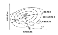
このようなハイブリッド車両1において、原動機として設けられた内燃機関10は、図2に示すように、その運転状態すなわち機関回転速度及び機関負荷に応じて燃料消費率が決まる。燃料消費率[g/kWh]が等しくなる運転状態(機関回転速度及び機関負荷)を図に実線で示し、以下に「等燃料消費率曲線」と記す。内燃機関10は、一般的に、機関回転速度が中程度であり、且つ機関負荷が中負荷から高負荷である運転状態において、燃料消費率が低くなる(効率が高くなる)傾向がある。   In such a hybrid vehicle 1, the internal combustion engine 10 provided as a prime mover has a fuel consumption rate determined according to its operating state, that is, the engine speed and the engine load, as shown in FIG. The operating state (engine speed and engine load) at which the fuel consumption rate [g / kWh] becomes equal is indicated by a solid line in the figure, and is hereinafter referred to as an “equal fuel consumption rate curve”. In general, the internal combustion engine 10 tends to have a low fuel consumption rate (high efficiency) in an operating state where the engine speed is medium and the engine load is medium to high.

加えて、内燃機関10においては、機関回転速度に応じて最も燃料消費率が低くなる機関負荷が決まる。機関回転速度に応じて最も燃料消費率が低くなる機関負荷を接続した線を図2に一点鎖線で示し、以下に「最適燃費線」と記す。HVECU100は、内燃機関10における燃料消費を抑制するために、運転状態(機関回転速度及び機関負荷)が最適燃費線上となるよう、内燃機関10を作動させる。なお、図において、機関負荷に機関回転速度を乗じた値となる機関出力が、同一となる運転状態を接続した線を図2に破線で示し、以下に「等機関出力線」と記す。   In addition, in the internal combustion engine 10, the engine load at which the fuel consumption rate is lowest is determined according to the engine speed. A line connecting the engine load having the lowest fuel consumption rate according to the engine rotation speed is shown by a one-dot chain line in FIG. 2, and is hereinafter referred to as an “optimum fuel consumption line”. In order to suppress fuel consumption in the internal combustion engine 10, the HVECU 100 operates the internal combustion engine 10 so that the operating state (engine rotational speed and engine load) is on the optimum fuel consumption line. In the figure, a line connecting operating states in which the engine output obtained by multiplying the engine load by the engine speed is the same as that of FIG. 2 is indicated by a broken line, and is hereinafter referred to as an “equal engine output line”.

しかし、HVECU100が、運転状態が最適燃費線上となるよう内燃機関10を作動させても、例えば、図に「定速」で示す運転状態のように、内燃機関10に要求される機関出力が比較的低い場合には、図に「加速」で示すように、内燃機関10に要求される機関出力が比較的高い場合に比べて燃料消費率が高くなる(効率が低くなる)傾向がある。   However, even if the HVECU 100 operates the internal combustion engine 10 so that the operation state is on the optimum fuel consumption line, the engine output required for the internal combustion engine 10 is compared as in the operation state indicated by “constant speed” in the figure, for example. When the engine power is low, as shown by “acceleration” in the figure, the fuel consumption rate tends to be higher (efficiency becomes lower) than when the engine output required for the internal combustion engine 10 is relatively high.

また、図3に要求出力Pev以下に示す領域のように、運転者により原動機すなわち内燃機関10及びモータMG1,MG2に要求される合計の出力すなわち要求出力が低い場合、要求出力の少なくとも一部を内燃機関10により発生させると、機関出力が低く、内燃機関10における燃料消費率が他の運転領域に比べて高くなる。よって、HVECU100は、要求出力がPev以下となる場合には、内燃機関10の作動を停止し非作動状態にして、内燃機関10の作動を停止させた車両走行すなわちモータMG2のみを選択使用するEV走行を行わせる。   Further, as shown in the region below the required output Pev in FIG. 3, when the total output required by the driver, that is, the internal combustion engine 10 and the motors MG1, MG2, that is, the required output is low, at least a part of the required output is obtained. When generated by the internal combustion engine 10, the engine output is low, and the fuel consumption rate in the internal combustion engine 10 is higher than in other operating regions. Therefore, when the required output becomes Pev or less, the HVECU 100 selects and uses only the vehicle traveling that stops the operation of the internal combustion engine 10, that is, the motor MG2, by stopping the operation of the internal combustion engine 10 and making it inoperative. Let it run.

一方、図3に要求出力Phv以上で示す領域のように、運転者により原動機に要求される要求出力が比較的高い場合、HVECU100は、要求出力の少なくとも一部を内燃機関10により発生させても、機関出力がさほど低くならず、燃料消費率が高くならないものと判断して、内燃機関10を始動し作動状態にして、原動機として内燃機関10を用いる車両走行すなわち上述のエンジン走行又はHV走行をハイブリッド車両1に行わせることが可能となっている。   On the other hand, when the required output requested by the motor by the driver is relatively high as in the region indicated by the required output Phv or more in FIG. 3, the HVECU 100 may cause the internal combustion engine 10 to generate at least a part of the required output. The engine output is determined not to decrease so much and the fuel consumption rate does not increase, and the internal combustion engine 10 is started and brought into an operating state, so that the vehicle traveling using the internal combustion engine 10 as a prime mover, that is, the above engine traveling or HV traveling is performed. The hybrid vehicle 1 can be made to perform.

このように構成されたハイブリッド車両1において、運転者により燃料消費の抑制を優先する走行が望まれており、且つ予め設定された車両速度域内に目標車速が設定された場合において、HVECU100は、車両速度域内において、内燃機関10を始動し、原動機として作動させた加速走行と、内燃機関10の作動を停止させた惰性走行とを交互に行って目標車速に沿って走行する車両走行(以下、加速惰性走行と記す)と、内燃機関10を原動機として継続して作動させて目標車速どおりに走行する車両走行(以下、定速走行と記す)とのいずれか一方をハイブリッド車両1に行わせることが可能となっており、加速惰性走行を行わせることで、定速走行を行わせる場合に比べて内燃機関10における燃料消費を抑制することができる。以下に詳細を、図2、図4及び図5を用いて説明する。   In the hybrid vehicle 1 configured as described above, when the driver wants to give priority to suppression of fuel consumption and the target vehicle speed is set within a preset vehicle speed range, the HVECU 100 Within the speed range, the vehicle traveling (hereinafter referred to as acceleration) that travels along the target vehicle speed by alternately performing acceleration traveling in which the internal combustion engine 10 is started and operated as a prime mover and inertial traveling in which the operation of the internal combustion engine 10 is stopped are alternately performed. The hybrid vehicle 1 can perform either one of a vehicle travel (hereinafter referred to as a constant speed travel) that continuously operates with the internal combustion engine 10 as a prime mover and travels at a target vehicle speed. It is possible, and the fuel consumption in the internal combustion engine 10 can be suppressed by performing the acceleration inertial traveling as compared with the case of performing the constant speed traveling.Details will be described below with reference to FIGS. 2, 4 and 5.

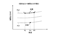
図4は、ハイブリッド車両が行う加速惰性走行の一例を示す図である。図5は、加速走行を行う場合と低速走行を行う場合における機関出力の差異を説明する図である。   FIG. 4 is a diagram illustrating an example of accelerated inertia traveling performed by the hybrid vehicle. FIG. 5 is a diagram for explaining a difference in engine output between the case where acceleration traveling is performed and the case where low speed traveling is performed.

運転者によりエコ運転スイッチ120がオン状態に操作されている場合等、運転者により燃料消費の抑制を優先することが選択されている場合、HVECU100は、まず、目標車速Vmを設定する。目標車速Vmは、例えば、アクセルオフ操作がなされて、アクセル操作量がゼロとなった時点の車速に設定される。なお、目標車速Vmは、HVECU100により設定されるものであれば良く、HVECU100がクルーズコントロール制御を行う際に、設定するものとしても良い。   When priority is given to restraining fuel consumption by the driver, such as when the eco-driving switch 120 is operated by the driver, the HVECU 100 first sets the target vehicle speed Vm. For example, the target vehicle speed Vm is set to the vehicle speed when the accelerator-off operation is performed and the accelerator operation amount becomes zero. The target vehicle speed Vm only needs to be set by the HVECU 100, and may be set when the HVECU 100 performs cruise control control.

加えて、HVECU100は、予め設定された車速域R内に、目標車速Vmが設定された場合に、当該目標車速Vmに従ってハイブリッド車両1を走行させる機能(以下、走行制御手段と記す)を有している。まず、HVECU100は、上述のように設定された目標車速Vmが、予め設定された車速域R内にあるか否かを判定する。この車速域Rは、例えば、約30km/h〜50km/h等、中低速で市街地を巡航するような領域に設定される。車速域Rの上限値VH(以下、単に「上限車速」と記す)と、車速域の下限値VL(以下、単に「下限車速」と記す)は、制御定数としてHVECU100のROM(図示せず)に記憶されている。   In addition, the HVECU 100 has a function of causing the hybrid vehicle 1 to travel according to the target vehicle speed Vm when the target vehicle speed Vm is set within a preset vehicle speed range R (hereinafter referred to as travel control means). ing. First, the HVECU 100 determines whether or not the target vehicle speed Vm set as described above is within a preset vehicle speed range R. The vehicle speed range R is set to a region that cruises the city area at a medium or low speed, such as about 30 km / h to 50 km / h. The upper limit value VH of the vehicle speed range R (hereinafter simply referred to as “upper limit vehicle speed”) and the lower limit value VL of the vehicle speed range (hereinafter simply referred to as “lower limit vehicle speed”) are ROM constants (not shown) of the HVECU 100 as control constants. Is remembered.

目標車速Vmが車速域R内にある場合、HVECU100は、図4に示すように、当該車速域R内において、内燃機関10を原動機として作動させた車両走行による加速走行と、内燃機関10の作動を停止させた惰性走行とを交互に行って、目標車速Vmに従って走行する「加速惰性走行」を行わせる。   When the target vehicle speed Vm is in the vehicle speed range R, as shown in FIG. 4, the HVECU 100 operates in the vehicle speed range R by the vehicle traveling with the internal combustion engine 10 as a prime mover and the operation of the internal combustion engine 10. The inertial traveling in which the vehicle is stopped is alternately performed to perform the “accelerated inertial traveling” that travels according to the target vehicle speed Vm.

詳細には、図4に点b→点aに示すように、上限車速VHから再び下限車速VLまでハイブリッド車両1を減速させる場合、HVECU100は、上限車速VHにおいて内燃機関10の作動を停止させて、当該上限車速VHから下限車速VLまで内燃機関10の作動を停止させた惰性走行を行わせる。この間、内燃機関10は、非作動状態であるため、燃料消費はゼロとなる。   Specifically, as shown by point b → point a in FIG. 4, when the hybrid vehicle 1 is decelerated again from the upper limit vehicle speed VH to the lower limit vehicle speed VL, the HVECU 100 stops the operation of the internal combustion engine 10 at the upper limit vehicle speed VH. Then, inertial running is performed with the operation of the internal combustion engine 10 stopped from the upper limit vehicle speed VH to the lower limit vehicle speed VL. During this time, the internal combustion engine 10 is in a non-operating state, so that fuel consumption is zero.

一方、図4に点a→点bに示すように、下限車速VLから上限車速VHまでハイブリッド車両1を加速走行させる場合、HVECU100は、下限車速VLにおいて内燃機関10を始動して、当該下限車速VLから上限車速VHまで内燃機関10を原動機として作動させたHV走行(又はエンジン走行)を行わせる。このように内燃機関10を原動機として作動させたHV走行により加速走行を行っている間、原動機(内燃機関10及びモータMG1,MG2)に要求される要求出力は、目標車速Vmで定速走行を行う場合に比べて高いものとなる。   On the other hand, when the hybrid vehicle 1 is accelerated from the lower limit vehicle speed VL to the upper limit vehicle speed VH as indicated by a point a → a point b in FIG. 4, the HVECU 100 starts the internal combustion engine 10 at the lower limit vehicle speed VL, HV traveling (or engine traveling) is performed by operating the internal combustion engine 10 as a prime mover from VL to the upper limit vehicle speed VH. In this way, during acceleration traveling by HV traveling with the internal combustion engine 10 operated as a prime mover, the required output required for the prime mover (internal combustion engine 10 and motors MG1, MG2) is constant speed travel at the target vehicle speed Vm. It is expensive compared to the case where it is performed.

このように原動機として内燃機関10を用いてハイブリッド車両1を車速域R内において加速走行させる場合、二次電池108からモータMG1,MG2への電力の供給(持ち出し)がないものを仮定すると、原動機に要求される要求出力は、そのまま内燃機関10が発生する機関出力となる。当該機関出力Pe3は、図5に示すように、原動機として内燃機関10のみを用いて目標車速Vmで定速走行を行った場合の機関出力Pe1に比べて大きくなる。   As described above, when the hybrid vehicle 1 is accelerated in the vehicle speed range R using the internal combustion engine 10 as a prime mover, it is assumed that there is no power supply (carrying out) from the secondary battery 108 to the motors MG1 and MG2. The required output required is the engine output generated by the internal combustion engine 10 as it is. As shown in FIG. 5, the engine output Pe3 is larger than the engine output Pe1 when the engine is driven at a constant vehicle speed Vm using only the internal combustion engine 10 as a prime mover.

当該車速域R内において内燃機関10を原動機として作動させたHV走行(又はエンジン走行)を行っている場合、車速域Rが比較的中低速に設定されているため、これに応じて機関回転速度も比較的低回転速度となる。このような場合、図2に示すように、加速走行を行って機関出力Pe3を発生させた方が、定速走行を行って機関出力Pe1を発生させるよりも燃料消費率が低くなる。   When HV traveling (or engine traveling) is performed in which the internal combustion engine 10 is operated as a prime mover within the vehicle speed range R, the vehicle speed range R is set to a relatively medium / low speed, and accordingly the engine rotational speed is set accordingly. Becomes a relatively low rotational speed. In such a case, as shown in FIG. 2, the fuel consumption rate is lower in the case where acceleration traveling is performed to generate the engine output Pe3 than in the case where constant speed traveling is performed to generate the engine output Pe1.

したがって、目標車速Vmが、予め設定された車速域R内にある場合、図4及び図5に示すように、HVECU100は、内燃機関10を原動機として作動させた加速走行(機関出力Pe3)と、燃料消費がゼロとなる内燃機関10の作動を停止させた惰性走行とを交互に行わせる「加速惰性走行」をハイブリッド車両1に行わせることで、原動機として内燃機関10を用いて目標車速Vmどおりに定速走行(機関出力Pe1)を継続して行わせる場合に比べて、内燃機関10における燃料消費を抑制することができる。   Therefore, when the target vehicle speed Vm is within the preset vehicle speed range R, as shown in FIGS. 4 and 5, the HVECU 100 performs acceleration travel (engine output Pe3) in which the internal combustion engine 10 is operated as a prime mover, By causing the hybrid vehicle 1 to perform “accelerated inertial traveling” that alternately performs inertial traveling in which the operation of the internal combustion engine 10 in which fuel consumption is zero is stopped, the internal combustion engine 10 is used as a prime mover, according to the target vehicle speed Vm. The fuel consumption in the internal combustion engine 10 can be suppressed as compared with the case where the constant speed running (engine output Pe1) is continuously performed.

なお、図4に示すように、加速走行の開始時に内燃機関10を始動させるため、加速惰性走行中において、内燃機関10を始動させる回数(以下、始動回数と記す)は、加速走行と惰性走行とを交互に繰り返す回数(以下、加減速繰り返し回数と記す)に一致している。加速惰性走行を継続する時間が長くなるに従って、加速惰性走行中に行われる始動回数は増加することとなる。   As shown in FIG. 4, since the internal combustion engine 10 is started at the start of the acceleration travel, the number of times the internal combustion engine 10 is started during the acceleration inertia travel (hereinafter referred to as the start frequency) is the acceleration travel and the inertia travel. And the number of times of repeating alternately (hereinafter referred to as the number of times of acceleration / deceleration). As the time for which the acceleration inertia traveling is continued becomes longer, the number of times of starting performed during the acceleration inertia traveling increases.

上述のように原動機として内燃機関10を備え、車両走行中に内燃機関10の作動を停止可能な車両において、内燃機関10を始動させ、原動機として作動させた加速走行と、内燃機関10の作動を停止させた惰性走行とを交互に行う「加速惰性走行」を行う場合、図4に点aで示すように、加速走行の開始ごとに内燃機関10を始動する必要があり、このとき、モータMG1,MG2において電力が消費されることとなる。内燃機関の始動1回あたりに必要な電力量である始動必要電力量は、内燃機関10や駆動装置20の温度等に応じて変化する。始動必要電力量が比較的大きくなる場合、加速惰性走行を行って燃料消費を抑制しても、内燃機関10の始動に供される合計の電力消費が大きくなってしまうという問題が生じる。   As described above, in a vehicle including the internal combustion engine 10 as a prime mover and capable of stopping the operation of the internal combustion engine 10 while the vehicle is running, the internal combustion engine 10 is started and the acceleration traveling that is actuated as the prime mover and the operation of the internal combustion engine 10 are performed. When performing “accelerated inertial traveling” that alternately performs the stopped inertial traveling, it is necessary to start the internal combustion engine 10 every time acceleration traveling starts, as indicated by a point a in FIG. 4. At this time, the motor MG1 , MG2 consumes power. The required starting power amount, which is the amount of power required per start of the internal combustion engine, varies according to the temperature of the internal combustion engine 10 and the drive device 20 and the like. When the required power amount for starting becomes relatively large, there is a problem that even if the acceleration inertial traveling is performed and the fuel consumption is suppressed, the total power consumption for starting the internal combustion engine 10 becomes large.

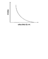
そこで、本実施形態に係るハイブリッド車両の制御手段としての車両用制御装置(HVECU)は、始動必要電力量が大きくなるに従って、加速惰性走行中に行われる内燃機関10の始動回数、すなわち加速惰性走行を継続する時間を低減させており、以下に、HVECUが実行する走行制御について図1〜図7を用いて説明する。図6は、HVECUが実行する走行制御を示すフローチャートである。図7は、HVECUが設定する、始動必要電力量に対する許容回数を示す図である。   Therefore, the vehicle control device (HVECU) as the hybrid vehicle control means according to the present embodiment increases the number of times the internal combustion engine 10 is started during the acceleration inertia traveling, that is, the acceleration inertia traveling as the required power amount for starting increases. The travel control executed by the HVECU will be described below with reference to FIGS. 1 to 7. FIG. 6 is a flowchart showing the travel control executed by the HVECU. FIG. 7 is a diagram showing the allowable number of times required for starting electric power set by the HVECU.

図6に示すように、ステップS100において、HVECU100は、各種制御変数を取得する。この制御変数には、目標車速Vm、機関水温Tw、及びエコ運転スイッチ120のオン/オフ状態、および始動必要電力量を制御変数として取得する。   As shown in FIG. 6, in step S100, the HVECU 100 acquires various control variables. As the control variables, the target vehicle speed Vm, the engine water temperature Tw, the on / off state of the eco-operation switch 120, and the required starting electric energy are acquired as control variables.

そして、ステップS102において、HVECU100は、エコ運転スイッチ120がオン状態であるか否かを判定する。すなわち、運転者により燃料消費を優先した車両走行が求められているか否かを判定している。エコ運転スイッチ120がオフ状態である(No)と判定された場合、HVECU100は、ステップS110において、原動機として内燃機関10を原動機として継続して作動させる定速走行を行わせる。   In step S102, the HVECU 100 determines whether or not the eco-operation switch 120 is in an on state. That is, it is determined whether or not the driver is demanded to drive the vehicle with priority on fuel consumption. If it is determined that the eco-operation switch 120 is in the off state (No), the HVECU 100 performs constant speed running in which the internal combustion engine 10 is continuously operated as a prime mover in step S110.

この場合、HVECU100は、図4に示すように、内燃機関10を原動機として作動させたHV走行又はエンジン走行により、目標車速Vmどおりに一定の車速でハイブリッド車両1を走行させる。HVECU100は、ハイブリッド車両1を、目標車速Vmどおりの車速で走行させるため、運転者に違和感を与えることがなく、運転性を良好なものにしている。   In this case, as shown in FIG. 4, the HVECU 100 causes the hybrid vehicle 1 to travel at a constant vehicle speed according to the target vehicle speed Vm by HV traveling or engine traveling with the internal combustion engine 10 operated as a prime mover. Since the HVECU 100 causes the hybrid vehicle 1 to travel at the vehicle speed equal to the target vehicle speed Vm, the driver does not feel uncomfortable and has good drivability.

一方、ステップS102において、エコ運転スイッチ120がオン状態である(Yes)と判定された場合、HVECU100は、ステップS104において、機関水温Twが、予め設定された暖機判定水温Tw1を上回るか否かを判定する。暖機判定水温Tw1は、内燃機関10及び駆動装置20の暖機が完了しているか否かを判断するための閾値であり、予め適合実験等により求められて、制御定数としてHVECU100のROMに記憶されている。   On the other hand, when it is determined in step S102 that the eco-operation switch 120 is in the on state (Yes), the HVECU 100 determines in step S104 whether the engine water temperature Tw exceeds a preset warm-up determination water temperature Tw1. Determine. The warm-up determination water temperature Tw1 is a threshold value for determining whether or not the internal combustion engine 10 and the drive device 20 have been warmed up. The warm-up determination water temperature Tw1 is obtained in advance by a conformance experiment or the like and stored in the ROM of the HVECU 100 as a control constant. Has been.

ステップS104において、機関水温Twが暖機判定水温Tw1以下であり、内燃機関10及び駆動装置20の暖機が完了していない(No)と判定された場合、HVECU100は、ステップS110において、内燃機関10を原動機として継続して作動させた定速走行を行い、内燃機関10を常時、作動状態にすることで暖機を促進する。   If it is determined in step S104 that the engine water temperature Tw is equal to or lower than the warm-up determination water temperature Tw1 and the warm-up of the internal combustion engine 10 and the drive device 20 is not completed (No), the HVECU 100 determines in step S110 that the internal combustion engine Warm-up is promoted by performing constant speed running with 10 as a prime mover and keeping the internal combustion engine 10 in an operating state at all times.

一方、ステップS104において、機関水温Twが暖機判定水温Tw1を上回る(Yes)場合には、HVECU100は、ステップS106において、目標車速Vmが予め設定された車速域R内にあるか否かを判定する。詳細には、図4に示すように、車速域Rを規定する下限車速VL及び上限車速VHと、目標車速Vmとの間において、以下の条件式(1)が成立するか否かを判定する。
VL<Vm<VH ・・・(1)
なお、本実施形態において、下限車速VL及び上限車速VHは、ハイブリッド車両1の車両諸元等に応じて予め設定されており、制御定数としてHVECU100のROMに記憶されている。
On the other hand, if the engine water temperature Tw exceeds the warm-up determination water temperature Tw1 in step S104 (Yes), the HVECU 100 determines in step S106 whether the target vehicle speed Vm is within a preset vehicle speed range R. To do. Specifically, as shown in FIG. 4, it is determined whether or not the following conditional expression (1) is satisfied between the lower limit vehicle speed VL and the upper limit vehicle speed VH that define the vehicle speed range R and the target vehicle speed Vm. .
VL <Vm <VH (1)
In the present embodiment, the lower limit vehicle speed VL and the upper limit vehicle speed VH are set in advance according to the vehicle specifications of the hybrid vehicle 1 and stored in the ROM of the HVECU 100 as control constants.

式(1)が成立しない、すなわち目標車速Vmが車速域R内にはない(No)と判定された場合、HVECU100は、ステップS110において、内燃機関10を原動機として継続して作動させる定速走行をハイブリッド車両1に行わせる。   When the formula (1) is not satisfied, that is, it is determined that the target vehicle speed Vm is not within the vehicle speed range R (No), the HVECU 100 is operated at a constant speed to continuously operate the internal combustion engine 10 as a prime mover in step S110. To the hybrid vehicle 1.

一方、式(1)が成立する、すなわち目標車速Vmが車速域Rにある(Yes)と判定された場合、HVECU100は、ステップS108において、加速惰性走行中における内燃機関10の始動回数が、予め設定された許容回数以下であるか否かを判定する。許容回数は、加速惰性走行中において内燃機関10の始動を許可するか否かを判定する閾値である。HVECU100は、図7に示すように、始動必要電力量が大きくなるに従って、許容回数を小さく設定する。なお、内燃機関10の始動回数は、加速惰性走行の開始時点において初期値としてゼロに設定されている。   On the other hand, when Formula (1) is satisfied, that is, when it is determined that the target vehicle speed Vm is in the vehicle speed range R (Yes), the HVECU 100 determines in advance in step S108 that the number of starts of the internal combustion engine 10 during the acceleration inertia traveling is It is determined whether or not the number is less than the set allowable number of times. The allowable number of times is a threshold value for determining whether or not to allow the start of the internal combustion engine 10 during acceleration inertia traveling. As shown in FIG. 7, the HVECU 100 sets the allowable number of times smaller as the required power amount for starting increases. Note that the number of start-ups of the internal combustion engine 10 is set to zero as an initial value at the start of acceleration inertia traveling.

ステップS120において内燃機関10の始動回数が許容回数以下である(Yes)と判定された場合、HVECU100は、内燃機関10を始動し、原動機として作動させた加速走行と、内燃機関10の作動を停止させた惰性走行とを交互に行って、目標車速Vmに従って走行する加速惰性走行を行わせる。   If it is determined in step S120 that the number of start times of the internal combustion engine 10 is equal to or less than the allowable number (Yes), the HVECU 100 starts the internal combustion engine 10 and stops the acceleration travel that is operated as a prime mover and the operation of the internal combustion engine 10. Accelerated inertial traveling that travels according to the target vehicle speed Vm is performed alternately with the inertial traveling that is performed.

詳細には、HVECU100は、図4に示すように、原動機として内燃機関10とモータMG1,MG2とを併用するHV走行により、下限車速VLから上限車速VHまでハイブリッド車両1を加速走行させる。上限車速VHに達すると、HVECU100は、内燃機関10の作動を停止して、内燃機関10の作動を停止させた惰性走行を開始する。そして、HVECU100は、下限車速VLに達するまで惰性走行によりハイブリッド車両1を減速させる。そして、図4に点aで示すように、下限車速VLに達すると、HVECU100は、非作動状態にある内燃機関10を始動する。   Specifically, as shown in FIG. 4, HVECU 100 accelerates hybrid vehicle 1 from the lower limit vehicle speed VL to the upper limit vehicle speed VH by HV traveling using the internal combustion engine 10 and motors MG1, MG2 as a prime mover. When the upper limit vehicle speed VH is reached, the HVECU 100 stops the operation of the internal combustion engine 10 and starts inertial running in which the operation of the internal combustion engine 10 is stopped. Then, HVECU 100 decelerates hybrid vehicle 1 by coasting until it reaches lower limit vehicle speed VL. Then, as indicated by a point a in FIG. 4, when the lower limit vehicle speed VL is reached, the HVECU 100 starts the internal combustion engine 10 in a non-operating state.

そして、HVECU100は、加速惰性走行中において内燃機関10を始動したときの始動必要電力量を取得して、当該始動必要電力量に応じて許容回数を新たに設定する(S122)と共に、内燃機関10の始動回数を加算する(S124)。   Then, the HVECU 100 acquires the required starting electric energy when starting the internal combustion engine 10 during the acceleration inertia traveling, and newly sets the allowable number of times according to the required starting electric energy (S122). Are added (S124).

これにより、加速惰性走行を継続する、すなわちステップS100からステップS124までのルーチンを繰り返すに従って、HVECU100は、始動必要電力量に応じて許容回数を最新の値に更新すると共に、始動回数を増加させていく。   As a result, the acceleration inertial running is continued, that is, as the routine from step S100 to step S124 is repeated, the HVECU 100 updates the allowable number of times to the latest value and increases the number of times of starting according to the required power amount for starting. Go.

そして、ステップS108において、始動回数が許容回数を上回る(No)と判定された場合、HVECU100は、加速惰性走行に替えて、ステップS110において、原動機として内燃機関10を原動機として継続して作動させる定速走行を行わせる。具体的には、HVECU100は、図4に示すように、内燃機関10を原動機として作動させたHV走行又はエンジン走行により、目標車速Vmどおりに一定の車速でハイブリッド車両1を走行させる。このように原動機として内燃機関10の作動を継続させる定速走行を行っている間、内燃機関10は、常時、作動状態となる。このため、内燃機関10の冷間時にあっては、機関水温Twが上昇し、内燃機関10、及び当該内燃機関10に結合された駆動装置20の暖機が促進されて、始動必要電力量が低下していくこととなる。   If it is determined in step S108 that the number of start times exceeds the allowable number (No), the HVECU 100 determines that the internal combustion engine 10 is continuously operated as a prime mover as a prime mover in step S110 instead of acceleration inertial running. Let the car run at high speed. Specifically, as shown in FIG. 4, the HVECU 100 causes the hybrid vehicle 1 to travel at a constant vehicle speed according to the target vehicle speed Vm by HV traveling or engine traveling with the internal combustion engine 10 actuated as a prime mover. As described above, the internal combustion engine 10 is always in an operating state while performing constant speed traveling that continues the operation of the internal combustion engine 10 as a prime mover. For this reason, when the internal combustion engine 10 is cold, the engine water temperature Tw rises, and warming up of the internal combustion engine 10 and the drive device 20 coupled to the internal combustion engine 10 is promoted, so that the required starting electric energy is reduced. It will decline.

なお、加速惰性走行に替えて定速走行を行わせるステップS110において、加速惰性走行中に加算された内燃機関10の始動回数をゼロに初期化する。   It should be noted that in step S110 in which constant speed travel is performed instead of acceleration inertia traveling, the number of times of starting the internal combustion engine 10 added during acceleration inertia traveling is initialized to zero.

以上に説明した走行制御ルーチンは、所定時間ごとに繰り返され、その都度、目標車速Vm、機関水温Tw、始動必要電力量等の制御変数が更新され、さらに始動必要電力量に応じて許容回数が新たに設定される。このようにして、HVECU100は、加速惰性走行中に行われる内燃機関10の始動回数すなわち加減速繰り返し回数を、始動必要電力量が大きくなるに従って低減させている。   The travel control routine described above is repeated every predetermined time, and each time, control variables such as the target vehicle speed Vm, the engine water temperature Tw, and the required starting electric energy are updated, and the allowable number of times is set according to the required starting electric energy. Newly set. In this way, the HVECU 100 reduces the number of times the internal combustion engine 10 is started during acceleration coasting, that is, the number of times of repeated acceleration / deceleration, as the required power for starting increases.

これにより、始動必要電力量が比較的小さい場合には、加速惰性走行を比較的長い時間継続して、内燃機関10における燃料消費を抑制しつつ、始動必要電力量が比較的大きい場合には、加速惰性走行を継続する時間を低減させて、その分、定速走行を行う時間を増大させる、すなわち、全走行時間のうち加速惰性走行を行わせる時間割合を低減させることで、加速惰性走行中において内燃機関10の始動に供される合計の電力消費を抑制することができる。   Thereby, when the required power amount for start-up is relatively small, the acceleration inertial running is continued for a relatively long time to suppress fuel consumption in the internal combustion engine 10, and when the required power amount for start-up is relatively large, Accelerated inertial running is reduced by reducing the time required to continue accelerated inertial travel, and thus increasing the time required for constant speed travel. The total power consumption provided for starting the internal combustion engine 10 can be suppressed.

以上に説明したように、本実施形態に係る車両用制御装置(HVECU)100は、原動機として内燃機関10を備え、車両走行中に内燃機関10の作動を停止可能なハイブリッド車両1に用いられる。HVECU100は、予め設定された車速域R内に車速の目標値である目標車速Vmが設定された場合に、当該車速域R内において、内燃機関10を始動させ、原動機として作動させた加速走行と、内燃機関10の作動を停止させた惰性走行とを交互に行って目標車速Vmに従って走行する加速惰性走行と、内燃機関10を原動機として継続して作動させて目標車速Vmに従って走行する定速走行との、いずれか一方をハイブリッド車両1に行わせることが可能な機能である走行制御手段と、内燃機関の始動1回あたりに必要な電力量である始動必要電力量を取得する機能である始動電力量取得手段とを有している。HVECU100の走行制御手段は、始動必要電力量が大きくなるに従って、加速惰性走行中に行う内燃機関10の始動回数を低減させるものとした。始動必要電力量が比較的大きい場合には、加速惰性走行中に行う内燃機関10の始動回数を低減させて、加速惰性走行中において内燃機関10の始動に供される合計の電力消費を抑制することができる。   As described above, the vehicle control apparatus (HVECU) 100 according to the present embodiment is used in the hybrid vehicle 1 that includes the internal combustion engine 10 as a prime mover and can stop the operation of the internal combustion engine 10 while the vehicle is traveling. When the target vehicle speed Vm, which is the target value of the vehicle speed, is set in the vehicle speed range R set in advance, the HVECU 100 starts the internal combustion engine 10 in the vehicle speed range R and performs acceleration travel that is operated as a prime mover. Accelerated inertial traveling that travels in accordance with the target vehicle speed Vm by alternately performing inertial traveling in which the operation of the internal combustion engine 10 is stopped, and constant-speed traveling in which the internal combustion engine 10 is continuously operated as the prime mover and travels in accordance with the target vehicle speed Vm. And a start function which is a function of acquiring a required starting electric energy which is an electric energy required for one start of the internal combustion engine. Power amount acquisition means. The traveling control means of the HVECU 100 is configured to reduce the number of times the internal combustion engine 10 is started during the acceleration inertia traveling as the required power amount for starting increases. When the required power amount for starting is relatively large, the number of times the internal combustion engine 10 is started during acceleration inertia traveling is reduced, thereby suppressing the total power consumption provided for starting the internal combustion engine 10 during acceleration inertia traveling. be able to.

HVECU100の走行制御手段は、加速惰性走行中における内燃機関10の始動回数が、予め設定された許容回数を上回る場合に、加速惰性走行に替えて定速走行を行わせるものであり、加速惰性走行中における内燃機関10の始動必要電力量が大きくなるに従って、前記許容回数を小さく設定するものとした。始動必要電力量が大きくなるに従って、加速惰性走行中における内燃機関の始動回数、すなわち加速惰性走行を継続する時間を低減すると共に、定速走行を行う時間を増大させ、全走行時間のうち加速惰性走行を行う時間割合を低減させる走行制御を容易に実現することができる。   The travel control means of the HVECU 100 is configured to perform a constant speed travel instead of the acceleration inertia traveling when the number of times the internal combustion engine 10 is started during the acceleration inertia traveling exceeds a preset allowable number of times. The allowable number of times is set to be smaller as the required power amount for starting the internal combustion engine 10 increases. As the required power for starting increases, the number of times the internal combustion engine is started during acceleration inertia traveling, that is, the time for continuing acceleration inertia traveling is reduced, and the time for constant speed traveling is increased. It is possible to easily realize traveling control that reduces the time ratio for traveling.

また、本実施形態において、ハイブリッド車両1は、原動機として内燃機関10とモータMG1,MG2とを備えるものであり、前記加速走行は、原動機として内燃機関10とモータMG1,MG2とを併用するHV走行、又は原動機として内燃機関10のみを選択使用するエンジン走行により行い、前記惰性走行は、ハイブリッド車両1の慣性力により惰性で走行させるものとした。これにより、内燃機関10を原動機として作動させた加速走行と、内燃機関10の作動を停止させた惰性走行とを交互に行う加速惰性走行を、クラッチ操作等の複雑な制御を行うことなく、原動機として内燃機関10とモータMG1,MG2とを備えた車両により容易に実現することができる。   Further, in the present embodiment, the hybrid vehicle 1 includes the internal combustion engine 10 and the motors MG1 and MG2 as a prime mover, and the acceleration traveling is an HV traveling that uses both the internal combustion engine 10 and the motors MG1 and MG2 as the prime mover. Alternatively, the inertia traveling is performed by the engine traveling using only the internal combustion engine 10 as a prime mover, and the inertia traveling is performed by the inertia force of the hybrid vehicle 1. As a result, the accelerating inertial traveling in which the accelerating traveling in which the internal combustion engine 10 is operated as the prime mover and the inertial traveling in which the operation of the internal combustion engine 10 is stopped can be performed alternately without performing complicated control such as clutch operation. This can be easily realized by a vehicle including the internal combustion engine 10 and the motors MG1, MG2.

なお、本実施形態において、本発明に係る車両は、原動機として内燃機関10とモータMG1,MG2とを備えたハイブリッド車両1であるものとしたが、本発明が適用可能な車両は、これに限定されるものではない。車両走行中に内燃機関の作動を停止可能な車両であれば、本発明を適用することができる。   In the present embodiment, the vehicle according to the present invention is the hybrid vehicle 1 including the internal combustion engine 10 and the motors MG1 and MG2 as the prime mover. However, the vehicle to which the present invention is applicable is limited to this. Is not to be done. The present invention can be applied to any vehicle that can stop the operation of the internal combustion engine while the vehicle is running.

以上のように、本発明は、原動機として内燃機関を備え、車両走行中に内燃機関の作動を停止可能な車両に有用であり、特に、原動機として内燃機関とモータとを備えたハイブリッド車両に適している。   As described above, the present invention is useful for a vehicle including an internal combustion engine as a prime mover and capable of stopping the operation of the internal combustion engine while the vehicle is running, and particularly suitable for a hybrid vehicle including the internal combustion engine and a motor as the prime mover. ing.

本実施形態に係るハイブリッド車両の概略構成を示す模式図である。It is a mimetic diagram showing a schematic structure of a hybrid vehicle concerning this embodiment. 内燃機関の機関回転速度及び機関負荷に対する燃料消費率及び機関出力の一例を示す図である。It is a figure which shows an example of the fuel consumption rate with respect to the engine speed of an internal combustion engine, and an engine load, and an engine output. 運転者により原動機に要求される要求出力と、内燃機関による燃料消費との関係の一例を示す図である。It is a figure which shows an example of the relationship between the request | requirement output requested | required of a motor | power_engine by a driver | operator, and the fuel consumption by an internal combustion engine. 本実施形態に係るハイブリッド車両が行う加速惰性走行の一例を示す図である。It is a figure which shows an example of the acceleration inertia running which the hybrid vehicle which concerns on this embodiment performs. 加速走行を行う場合と定速走行を行う場合との機関出力の差異を説明する図である。It is a figure explaining the difference of the engine output by the case where acceleration driving | running | working and the case of performing constant speed driving | running | working. 本実施形態に係る車両用制御装置(HVECU)が実行する走行制御を示すフローチャートである。It is a flowchart which shows the traveling control which the vehicle control apparatus (HVECU) which concerns on this embodiment performs. 本実施形態に係る車両用制御装置(HVECU)が設定する、始動必要電力量に対する許容回数を示す図である。It is a figure which shows the allowable frequency | count with respect to the electric power required for a start which the vehicle control apparatus (HVECU) which concerns on this embodiment sets.

符号の説明Explanation of symbols

1 ハイブリッド車両
10 内燃機関
11 水温センサ
20 駆動装置
30 動力分割統合機構(動力伝達機構)
30a 動力分割遊星歯車
30c 減速遊星歯車
34 プラネタリキャリア
36a,36c 動力分割統合機構のリングギア
44 カウンタドライブギア
51,52 モータジェネレータのロータ
53,54 モータジェネレータのステータ
61,62 インバータ
66 モータジェネレータ用の電子制御装置(モータECU)
70 減速機構(動力伝達機構)
74 カウンタドリブンギア
78 ファイナルドライブギア
80 差動機構(動力伝達機構)
82 差動機構のリングギア
90 駆動軸
94 駆動輪
108 二次電池(蓄電池)
110 アクセルペダル
112 アクセルペダルポジションセンサ
120 エコ運転スイッチ
MG1,MG2 モータジェネレータ(回転電機)
100 ハイブリッド車両用の電子制御装置(車両用制御装置、ECU、走行制御手段、始動電力量取得手段、目標車速設定手段、記憶手段)
DESCRIPTION OF SYMBOLS 1 Hybrid vehicle 10 Internal combustion engine 11 Water temperature sensor 20 Drive apparatus 30 Power split integrated mechanism (power transmission mechanism)
30a Power split planetary gear 30c Reduction planetary gear 34 Planetary carrier 36a, 36c Ring gear of power split integration mechanism 44 Counter drive gear 51, 52 Motor generator rotor 53, 54 Motor generator stator 61, 62 Inverter 66 Motor generator electronics Control device (motor ECU)
70 Deceleration mechanism (power transmission mechanism)
74 Counter driven gear 78 Final drive gear 80 Differential mechanism (power transmission mechanism)
82 Ring gear of differential mechanism 90 Drive shaft 94 Drive wheel 108 Secondary battery (storage battery)
110 Accelerator pedal 112 Accelerator pedal position sensor 120 Eco-operation switch MG1, MG2 Motor generator (rotary electric machine)
100 Electronic control device for hybrid vehicle (vehicle control device, ECU, travel control means, starting power amount acquisition means, target vehicle speed setting means, storage means)

Claims (3)

原動機として内燃機関を備え、車両走行中に内燃機関の作動を停止可能な車両に用いられる車両用制御装置であって、
予め設定された車速域内に車速の目標値である目標車速が設定された場合に、当該車速域内において、内燃機関を始動させ、原動機として作動させた加速走行と、内燃機関の作動を停止させた惰性走行とを交互に行って目標車速に従って走行する加速惰性走行と、内燃機関を原動機として継続して作動させて目標車速に従って走行する定速走行との、いずれか一方を車両に行わせることが可能な走行制御手段と、
内燃機関の始動1回あたりに必要な電力量である始動必要電力量を取得する始動電力量取得手段と、
を有し、
走行制御手段は、始動必要電力量が大きくなるに従って、加速惰性走行中に行う内燃機関の始動回数を低減させる
ことを特徴とする車両用制御装置。
A vehicle control device used for a vehicle including an internal combustion engine as a prime mover and capable of stopping the operation of the internal combustion engine during vehicle travel,
When a target vehicle speed, which is a target value of the vehicle speed, is set within a preset vehicle speed range, the internal combustion engine is started in the vehicle speed range, and the acceleration traveling that is operated as a prime mover and the operation of the internal combustion engine are stopped. It is possible to cause the vehicle to perform either one of acceleration inertial traveling that travels according to the target vehicle speed by alternately performing inertial traveling and constant speed traveling that continuously operates using the internal combustion engine as a prime mover and travels according to the target vehicle speed. Possible travel control means;
A starting power amount acquisition means for acquiring a required starting power amount which is an amount of power required per start of the internal combustion engine;
Have
The traveling control means reduces the number of times the internal combustion engine is started during acceleration inertia traveling as the required power amount for starting increases.
請求項1に記載の車両用制御装置において、
走行制御手段は、
加速惰性走行中における内燃機関の始動回数が、予め設定された許容回数を上回る場合に、加速惰性走行に替えて定速走行を行わせるものであり、
始動必要電力量が大きくなるに従って、前記許容回数を小さく設定する
ことを特徴とする車両用制御装置。
The vehicle control device according to claim 1,
The travel control means
When the number of start times of the internal combustion engine during the acceleration inertia traveling exceeds a preset allowable number, the constant inertia traveling is performed instead of the acceleration inertia traveling,
The vehicle control device, wherein the allowable number of times is set to be smaller as the required power amount for starting becomes larger.
請求項1又は2に記載の車両用制御装置において、
車両は、原動機として内燃機関とモータとを備えるものであり、
前記加速走行は、原動機として内燃機関とモータとを併用するHV走行、又は原動機として内燃機関のみを選択使用するエンジン走行により行い、
前記惰性走行は、車両の慣性力により惰性で走行させる
ことを特徴とする車両用制御装置。
The vehicle control device according to claim 1 or 2,
The vehicle includes an internal combustion engine and a motor as a prime mover,
The accelerated traveling is performed by HV traveling using both an internal combustion engine and a motor as a prime mover, or by engine traveling using only an internal combustion engine as a prime mover,
The inertial traveling is caused by inertial force of the vehicle to travel inertially.
JP2008147294A 2008-06-04 2008-06-04 Controller for vehicle Pending JP2009293490A (en)

Priority Applications (1)

Application Number Priority Date Filing Date Title
JP2008147294A JP2009293490A (en) 2008-06-04 2008-06-04 Controller for vehicle

Applications Claiming Priority (1)

Application Number Priority Date Filing Date Title
JP2008147294A JP2009293490A (en) 2008-06-04 2008-06-04 Controller for vehicle

Publications (1)

Publication Number Publication Date
JP2009293490A true JP2009293490A (en) 2009-12-17

Family

ID=41541882

Family Applications (1)

Application Number Title Priority Date Filing Date
JP2008147294A Pending JP2009293490A (en) 2008-06-04 2008-06-04 Controller for vehicle

Country Status (1)

Country Link
JP (1) JP2009293490A (en)

Cited By (4)

* Cited by examiner, † Cited by third party
Publication number Priority date Publication date Assignee Title
WO2011092855A1 (en) * 2010-01-29 2011-08-04 トヨタ自動車株式会社 Vehicle control device
JP2016130054A (en) * 2015-01-13 2016-07-21 株式会社デンソー Electronic control unit
JPWO2014122761A1 (en) * 2013-02-07 2017-01-26 トヨタ自動車株式会社 Hybrid vehicle travel control device
JP2017171005A (en) * 2016-03-22 2017-09-28 トヨタ自動車株式会社 Power supply system for vehicle

Cited By (5)

* Cited by examiner, † Cited by third party
Publication number Priority date Publication date Assignee Title
WO2011092855A1 (en) * 2010-01-29 2011-08-04 トヨタ自動車株式会社 Vehicle control device
JP5267685B2 (en) * 2010-01-29 2013-08-21 トヨタ自動車株式会社 Vehicle control device
JPWO2014122761A1 (en) * 2013-02-07 2017-01-26 トヨタ自動車株式会社 Hybrid vehicle travel control device
JP2016130054A (en) * 2015-01-13 2016-07-21 株式会社デンソー Electronic control unit
JP2017171005A (en) * 2016-03-22 2017-09-28 トヨタ自動車株式会社 Power supply system for vehicle

Similar Documents

Publication Publication Date Title
JP5304350B2 (en) Vehicle control device
JP2010006309A (en) Control device for vehicle
US8428803B2 (en) Hybrid vehicle and method for controlling hybrid vehicle
JP4348557B2 (en) Control device for hybrid electric vehicle
JP4225314B2 (en) Hybrid vehicle
JP2010280363A (en) Controller for vehicle
WO2012098658A1 (en) Hybrid vehicle and method of controlling same
JP2010013042A (en) Vehicle controller
JP5598555B2 (en) Vehicle and vehicle control method
JP2009029314A (en) Driving force control device for vehicle
US8942877B2 (en) Hybrid vehicle and method for controlling the same
JP2011063089A (en) Device for control of hybrid electric vehicle
JP2006312352A (en) Control device for driving system
JP2009143306A (en) Internal combustion engine device and control method thereof, and power output device
WO2014083996A1 (en) Travel control device
JP5644868B2 (en) Vehicle and vehicle control method
JP2010280281A (en) Controller for vehicle
JP2009293490A (en) Controller for vehicle
JP2005020955A (en) Charging and discharging control device for energy storage device and car
JP2009292291A (en) Control device for vehicle
JP5810580B2 (en) Vehicle and vehicle control method
JP4000750B2 (en) Power output apparatus and control method thereof
JP2010208480A (en) Hybrid vehicle
WO2012105019A1 (en) Vehicle and method for controlling vehicle
JP5724840B2 (en) Hybrid vehicle