JP2009284564A - Power conversion device for vehicle - Google Patents
Power conversion device for vehicle Download PDFInfo
- Publication number
- JP2009284564A JP2009284564A JP2008130966A JP2008130966A JP2009284564A JP 2009284564 A JP2009284564 A JP 2009284564A JP 2008130966 A JP2008130966 A JP 2008130966A JP 2008130966 A JP2008130966 A JP 2008130966A JP 2009284564 A JP2009284564 A JP 2009284564A
- Authority
- JP
- Japan
- Prior art keywords
- synchronous rectification
- switching
- switching element
- execution permission
- side arm
- Prior art date
- Legal status (The legal status is an assumption and is not a legal conclusion. Google has not performed a legal analysis and makes no representation as to the accuracy of the status listed.)
- Granted
Links
Images


Abstract
Description
この発明は、交流発電電動機と直流電源との間に接続される車両用電力変換装置に関するものである。 The present invention relates to a vehicle power converter connected between an AC generator motor and a DC power source.
内燃機関を始動するために電動機として駆動動作を行ない、内燃機関駆動後は発電機として発電動作を行う車載用発電電動機(以下、単に、発電電動機と称する)を搭載した自動車等の車両には、バッテリー等の直流機器と交流機器である発電電動機との間の電力変換を行う車両用電力変換装置が用いられる。 A vehicle such as an automobile equipped with a vehicle-mounted generator motor (hereinafter simply referred to as a generator motor) that performs a drive operation as an electric motor to start the internal combustion engine and performs a power generation operation as a generator after driving the internal combustion engine, A vehicle power conversion device that performs power conversion between a DC device such as a battery and a generator motor that is an AC device is used.
一般に、このような車両用電力変換装置は、発電電動機とバッテリーとの間に接続され、複数のスイッチング素子とこれらのスイッチング素子に並列接続されたダイオード素子(例えば、スイッチング素子に付随して設けられた寄生ダイオード)により構成されている。車両用電力変換機は、発電電動機が電動機として動作する場合には、スイッチング素子のオン期間とオフ期間との制御であるスイッチング制御を行なうことによりバッテリーからの直流電力を交流電力に変換して発電電動機に供給し、発電電動機が発電機として動作する場合には、発電電動機が発電した交流電力を前述のダイオードにより整流して直流電力に変換しバッテリーに供給する。 In general, such a vehicle power converter is connected between a generator motor and a battery, and a plurality of switching elements and diode elements connected in parallel to these switching elements (for example, provided in association with the switching elements). Parasitic diode). When the generator motor operates as an electric motor, the vehicular power converter converts the DC power from the battery into AC power by performing switching control, which is control between the ON period and the OFF period of the switching element. When supplied to the motor and the generator motor operates as a generator, the AC power generated by the generator motor is rectified by the aforementioned diode, converted into DC power, and supplied to the battery.
従来、車両に搭載された回転電機の回転子の回転位置を位置検出手段により検出し、この検出した位置情報に基づいてスイッチング素子のスイッチング制御を行なうようにした車両用電力変換装置が既に提案されている(例えば、特許文献1参照)。又、近年では、ダイオード整流よりも効率がよく、素子の発熱も少ないことから、スイッチング素子による同期整流を用いた車両用電力変換装置が提案されている。 2. Description of the Related Art Conventionally, a vehicular power conversion apparatus has been proposed in which a rotation position of a rotor of a rotating electrical machine mounted on a vehicle is detected by a position detection unit, and switching control of a switching element is performed based on the detected position information. (For example, refer to Patent Document 1). Further, in recent years, a vehicle power converter using synchronous rectification by a switching element has been proposed because it is more efficient than diode rectification and generates less heat from the element.
通常、同期整流を用いた車両用電力変換装置は、発電電動機が発電を開始すると、スイッチング素子と並列に接続されたダイオードによってダイオード整流が行われ、その後、エンジンの回転速度が上昇し発電電動機での発電量が増加すると、ダイオード整流からスイッチング素子による同期整流へと移行する。 Normally, when a generator motor starts power generation, a vehicle power converter using synchronous rectification performs diode rectification by a diode connected in parallel with a switching element, and then the rotational speed of the engine increases and the generator motor When the power generation amount increases, the diode rectification shifts to the synchronous rectification by the switching element.
しかしながら、このような車両用電力変換装置に於いて、同期整流制御部では実施許可信号に基づいてスイッチング素子のスイッチングタイミングが演算されるが、実施許可信号がノイズの影響で正確なタイミングが得られない場合、同期整流制御部は正確な許可信号が出力できないという課題があった。 However, in such a vehicular power converter, the synchronous rectification control unit calculates the switching timing of the switching element based on the execution permission signal, but the execution permission signal can obtain an accurate timing due to the influence of noise. If not, there is a problem that the synchronous rectification control unit cannot output an accurate permission signal.
又、同期整流制御部は、実施許可信号に基づき通電中心位置から徐々に通電幅を上げるようにスイッチング制御を行なうため、演算量が多くマイコンの演算負荷が大きくなるという課題があった。 Further, since the synchronous rectification control unit performs switching control so as to gradually increase the energization width from the energization center position based on the execution permission signal, there is a problem that the calculation amount is large and the calculation load of the microcomputer is increased.
又、特許文献1に記載された従来の装置では、回転子位置を検知する手段を用いてスイッチング素子の位相制御を行なうが、例えば負荷変動等により回転子位置が急激に変化するような場合に対しては、適応が難しかった。
In the conventional apparatus described in
この発明は、従来の装置に於ける前述の課題を解決するためになされたものであり、直流電力と交流電力との電力変換を行なう車両用電力変換装置に於いて、同期整流時に同期整流許可信号に基づき同期整流制御部にて正確なスイッチングタイミングを演算し、高効率且つノイズに強く安定した電力を供給することができる車両用電力変換装置を提供することを目的とする。 The present invention has been made to solve the above-mentioned problems in conventional devices, and in a vehicle power conversion device that performs power conversion between DC power and AC power, synchronous rectification is permitted during synchronous rectification. It is an object of the present invention to provide a vehicular power converter that can calculate accurate switching timing in a synchronous rectification control unit based on a signal and can supply highly efficient, noise-resistant and stable power.
この発明による車両用電力変換装置は、多相ブリッジ回路の各相の正極側アーム及び各相の負極側アームを構成し夫々並列接続されたダイオードを有する複数のスイッチング素子を備え、外部から駆動されて多相交流電力を発生する発電電動機と直流機器との間に接続され、前記多相交流電力の発生時に前記夫々のダイオードの導通状態に同期して前記夫々のダイオードに対応する前記スイッチング素子を導通させて同期整流を実施し得るように構成された車両用電力変換装置であって、前記ダイオードの導通状態の周期に対応した周期を有し前記ダイオードに対応する前記スイッチング素子に対する同期整流の実施許可信号を発生する同期整流許可手段と、前記実施許可信号の周期に基づいてその実施許可信号に対応する前記スイッチング素子に対するスイッチングタイミング信号を発生する同期整流制御手段とを備え、前記同期整流制御手段からの前記スイッチングタイミング信号に基づいて前記対応するスイッチング素子をスイッチング制御して前記同期整流を実施することを特徴とするものである。 A power converter for a vehicle according to the present invention includes a plurality of switching elements having diodes connected in parallel, each of which constitutes a positive-side arm and a negative-side arm of each phase of a multiphase bridge circuit, and is driven from the outside. A switching motor that is connected between a generator motor that generates multiphase AC power and a DC device, and that corresponds to each of the diodes in synchronization with the conduction state of each of the diodes when the multiphase AC power is generated. A vehicle power converter configured to be able to conduct synchronous rectification by being conducted, wherein synchronous rectification is performed on the switching element corresponding to the diode having a period corresponding to the period of conduction of the diode Synchronous rectification permission means for generating a permission signal, and the switching corresponding to the execution permission signal based on the period of the execution permission signal Synchronous rectification control means for generating a switching timing signal for a child, and performing the synchronous rectification by switching control of the corresponding switching element based on the switching timing signal from the synchronous rectification control means, To do.
この発明に於いて、好適には、前記同期整流制御手段は、前記各相全ての前記正極側アーム及び負極側アームに対応する前記実施許可信号の周期に基づき、前記夫々の正極側アーム及び負極側アームに対応する前記スイッチング素子に対するスイッチングタイミング信号を発生するように構成される。 In the present invention, preferably, the synchronous rectification control means is configured to use the positive-side arm and the negative electrode based on the period of the execution permission signal corresponding to the positive-side arm and the negative-side arm of all the phases. A switching timing signal is generated for the switching element corresponding to the side arm.
又、この発明に於いて、好適には、前記同期整流制御手段は、前記各相全ての前記正極側アーム及び負極側アームに対応する前記実施許可信号の周期のうち最小時間の周期を選択し、前記選択した最小時間の周期に基づいて前記スイッチング素子に対するスイッチングタイミング信号を発生するように構成される。 In the present invention, it is preferable that the synchronous rectification control means selects a period of the minimum time among the periods of the execution permission signal corresponding to the positive side arm and the negative side arm of all the phases. , And configured to generate a switching timing signal for the switching element based on the selected minimum time period.
又、この発明に於いて、好適には、前記同期整流制御手段は、前記各相全ての前記正極側アーム及び負極側アームに対応する前記実施許可信号の周期の平均時間を演算し、前記演算した平均時間に基づいて前記スイッチング素子に対するスイッチングタイミング信号を発生するように構成される。 In the present invention, preferably, the synchronous rectification control means calculates an average time of the period of the execution permission signal corresponding to the positive side arm and the negative side arm of all the phases, and the calculation A switching timing signal for the switching element is generated based on the average time.
更に、この発明に於いて、好適には、前記同期整流制御手段は、前記各相全ての前記正極側アームに対応する前記実施許可信号の周期のうち最小時間の周期に基づいて前記各相全ての前記正極側アームに対応する前記スイッチング素子に対するスイッチングタイミング信号を発生すると共に、前記各相全ての前記負極側アームに対応する前記実施許可信号の周期のうち最小時間の周期に基づいて前記各相全ての前記負極側アームに対応する前記スイッチング素子に対するスイッチングタイミング信号を発生するように構成される。 Furthermore, in the present invention, preferably, the synchronous rectification control means is configured so that all the phases are based on a cycle of a minimum time among cycles of the execution permission signals corresponding to the positive-side arms of all the phases. Generating a switching timing signal for the switching element corresponding to the positive-side arm of the phase, and each phase based on a cycle of a minimum time among cycles of the execution permission signal corresponding to the negative-side arm of all the phases. It is configured to generate switching timing signals for the switching elements corresponding to all the negative side arms.
更に、この発明に於いて、好適には、前記同期整流制御手段は、前記各相全ての前記正極側アームに対応する前記実施許可信号の周期の平均時間を演算しその平均時間に基づいて前記各相全ての前記正極側アームに対応する前記スイッチング素子に対するスイッチングタイミング信号を発生すると共に、前記各相全ての前記負極側アームに対応する前記実施許可信号の周期の平均時間を演算しその平均時間に基づいて前記各相全ての前記負極側アームに対応する前記スイッチング素子に対するスイッチングタイミング信号を発生するように構成される。 Further, in the present invention, preferably, the synchronous rectification control means calculates an average time of the period of the execution permission signal corresponding to the positive arm of all the phases, and based on the average time, Generates a switching timing signal for the switching element corresponding to the positive side arm of all phases, calculates an average time of the period of the execution permission signal corresponding to the negative side arm of all phases, and calculates the average time The switching timing signal for the switching element corresponding to the negative arm of all the phases is generated based on
又、この発明に於いて、好適には、前記同期整流制御手段は、前記各相全ての前記正極側アーム及び負極側アームに対応する前記実施許可信号のうち何れか1つ以上の実施許可信号を選択し、前記選択した実施許可信号の周期に基づいて前記スイッチング素子に対するスイッチングタイミング信号を発生するように構成される。 In the present invention, it is preferable that the synchronous rectification control means includes at least one execution permission signal among the execution permission signals corresponding to the positive arm and the negative arm of all the phases. And a switching timing signal for the switching element is generated based on the period of the selected execution permission signal.
又、この発明に於いて、好適には、前記同期整流制御手段は、前記実施許可信号のうち少なくとも1つの周期が所定値と異なるときは、前記スイッチング信号の発生を停止し、前記同期整流の実施を停止するように構成される。 In the present invention, preferably, the synchronous rectification control means stops the generation of the switching signal when at least one period of the execution permission signal is different from a predetermined value, and performs the synchronous rectification. Configured to stop implementation.
更に、この発明に於いて、好適には、前記発電電動機の界磁電流を検出する界磁電流検出手段と、前記発電電動機の回転数を検出する回転数検出手段と、前記回転数検出手段により検出した回転数に応じて前記同期整流の実施を停止すべき界磁電流値を演算する同期整流停止手段とを備え、前記同期整流制御手段は、前記界磁電流検出手段により検出した界磁電流の値が前記同期整流停止手段により演算された前記界磁電流値以下となったとき、前記スイッチングタイミング信号の発生を停止して前記同期整流の実施を停止するように構成される。 Further, in the present invention, preferably, the field current detecting means for detecting the field current of the generator motor, the rotational speed detecting means for detecting the rotational speed of the generator motor, and the rotational speed detecting means. Synchronous rectification stop means for calculating a field current value to stop the execution of the synchronous rectification according to the detected number of rotations, the synchronous rectification control means, the field current detected by the field current detection means When the value becomes equal to or less than the field current value calculated by the synchronous rectification stopping means, the generation of the switching timing signal is stopped and the execution of the synchronous rectification is stopped.
この発明に係る車両用電力変換装置によれば、スイッチング素子に並列接続されたダイオードの導通状態の周期に対応した周期を有し前記ダイオードに対応する前記スイッチング素子に対する同期整流の実施許可信号を発生する同期整流許可手段と、前記実施許可信号の周期に基づいてその実施許可信号に対応する前記スイッチング素子に対するスイッチングタイミング信号を発生する同期整流制御手段とを備え、前記同期整流制御手段からの前記スイッチングタイミング信号に基づいて前記対応するスイッチング素子をスイッチング制御して前記同期整流を実施するようにしたので、ノイズに強く安定した同期整流制御を継続することが可能であり、高効率且つ安定した発電を車両に供給することができる。 According to the vehicular power conversion device of the present invention, the synchronous rectification execution permission signal is generated for the switching element corresponding to the diode having a period corresponding to the period of the conduction state of the diode connected in parallel to the switching element. And a synchronous rectification control means for generating a switching timing signal for the switching element corresponding to the execution permission signal based on a cycle of the execution permission signal, and the switching from the synchronous rectification control means Since the synchronous rectification is performed by controlling the corresponding switching element based on the timing signal, it is possible to continue the synchronous rectification control that is resistant to noise and achieves highly efficient and stable power generation. It can be supplied to the vehicle.
実施の形態1.
図1は、発電電動機を搭載した車両システムの構成を示す説明図である。図1に於いて、発電電動機102は、例えばベルト等の動力伝達手段104を介して内燃機関101に接続されている。内燃機関101の運転中は、発電電動機102が発電した交流電力を電力変換装置により直流電力に変換して蓄電池103に供給しこれを所定電圧に充電する。一方、内燃機関101を始動するときには、蓄電池103からの直流電力を電力変換装置により交流電力に変換して電動発電機102に供給しこれを電動機として動作させ、内燃機関101を駆動して始動させる。
FIG. 1 is an explanatory diagram showing the configuration of a vehicle system equipped with a generator motor. In FIG. 1, a
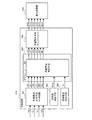
図2は、この発明の実施の形態1による車両用電力変換装置を備えた発電電動機102の内部構成を示す構成図である。図2に於いて、発電電動機102は、電力変換装置110とモータジェネレータ部200により構成されている。電力変換装置110は、電力変換部220とスイッチング素子のオン・オフ制御を行う制御装置210とを備えている。
FIG. 2 is a configuration diagram showing an internal configuration of the
電力変換部220は、モータジェネレータ部200の界磁コイル202に通電する界磁電流をPWM制御するための界磁スイッチング素子221とフリーホイールダイオード222を備える。又、電力変換部220は、U相正極側アームUHAを構成するU相正極側アームスイッチング素子(以下、スイッチング素子UHと称する)223a、V相正極側アームVHAを構成するV相正極側アームスイッチング素子(以下、スイッチング素子VHと称する)223b、W相正極側アームWHAを構成するW相正極側アームスイッチング素子(以下、スイッチング素子WHと称する)223c、及び、U相負極側アームULAを構成するU相負極側アームスイッチング素子(以下、スイッチング素子ULと称する)224a、V相負極側アームVLAを構成するV相負極側アームスイッチング素子(以下、スイッチング素子VLと称する)224b、W相負極側アームWLAを構成するW相負極側アームスイッチング素子(以下、スイッチング素子WLと称する)224cとにより構成された3相ブリッジ回路を備える。
The
スイッチング素子UH223a、VH223b、WH223c、UL224a、VL224b、WL224cとは、夫々図示のように、夫々逆並列接続された寄生ダイオードを内蔵している。 The switching elements UH223a, VH223b, WH223c, UL224a, VL224b, and WL224c each incorporate a parasitic diode connected in antiparallel as shown in the figure.
尚、正極側アームを上アーム、負極側アームを下アームと称することもあるが、以下の説明では正極側アーム、負極側アームの呼称を用いる。 The positive arm is sometimes referred to as the upper arm, and the negative arm is referred to as the lower arm. In the following description, the positive arm and the negative arm are used.
モータジェネレータ部200の電機子コイル201は、その3相の各相端子が電力変換部220の交流側端子U、V、Wに接続されている。バッテリー103の正極側端子及び負極側端子は、夫々電力変換部220の直流側端子P、Nに接続されている。
The
電力変換部220の三相ブリッジ回路を構成する各スイッチング素子UH223a、VH223b、WH223c、UL224a、VL224b、WL224c、及び界磁スイッチング素子221は、後述するように制御装置210から与えられるゲート信号によりスイッチング制御される。
The switching elements UH223a, VH223b, WH223c, UL224a, VL224b, WL224c, and the
尚、図2では、モータジェネレータ部200を、三相の電機子コイル201と界磁コイル202を備えた三相界磁コイル方式発電電動機として示しているが、相数や界磁方式(例えば、永久磁石等)が異なっていてもよい。更に、図2では、発電電動機102を電力変換装置110とモータジェネレータ部200が一体構造とされた一体構造式発電電動機装置として示しているが、電力変換装置110と発電電動機200とが物理的に分割された別体構造式発電電動装置であってもよい。
In FIG. 2, the
図3は、前述の制御装置210の構成を示すブロック図である。図3に於いて、制御装置210及びマイコン304は、図3の表示した機能以外にも車両用電力変換装置の様々な機能を有するが、以下の説明ではこの発明の実施の形態1に関係する部分を主体に説明する。図3に於いて、同期整流許可手段301は、電力変換部220の負極側端子Nの電位を基準に、正極側端子Pの電圧Vp、三相の各端子U、V、Wの端子電圧Vu、Vv、Vwが入力され、三相ブリッジ回路の各スイッチング素子UH223a、VH223b、WH223cと、UL224a、VL224b、WL224cをオンにしない状態で寄生ダイオードに順方向電流が流れるかどうかを、電圧Vpと三相の各端子電圧Vu、Vv、Vwとに基づいて検出する。
FIG. 3 is a block diagram illustrating a configuration of the
動機整流許可手段301は、前述の各寄生ダイオードに順方向電流が流れるかどうかの検出の結果、寄生ダイオードが順方向電流の流れるオン状態であればハイレベルHi、順方向電流の流れないオフ状態であればローレベルLowとして、三相ブリッジ回路の全正極側アームのダイオードの導通状態の周期に対応する周期の実施許可信号UH、VH、WHを出力し、全負極側アームのダイオードの導通状態の周期に対応する周期の実施許可信号UL、VL、WLを夫々出力する。 The motivation rectification permitting means 301 is a high level Hi if the parasitic diode is in an on state in which a forward current flows as a result of detecting whether or not a forward current flows in each of the parasitic diodes, and in an off state in which no forward current flows. If so, the execution permission signals UH, VH, and WH having a period corresponding to the period of the conduction state of the diodes of all the positive side arms of the three-phase bridge circuit are output as the low level Low, and the conduction state of the diodes of the all negative side arms The execution permission signals UL, VL, WL having a period corresponding to the period are respectively output.
同期整流許可手段301に於ける前述の寄生ダイオードのオン、オフ状態の検出は、周知の技術を用いればよい。尚、ここでは、入力される電圧Vu、Vv、VwがハイレベルHiの時はそれに対応する寄生ダイオードがオン状態であり、ローレベルLowの時は、それに対応する寄生ダイオードがオフ状態であるとしているが、その逆の状態としてもよい。又、入力される電圧Vu、Vv、Vwのエッジ検出により、アップエッジが入力されたときは寄生ダイオードがオン状態、ダウンエッジが入力されたときはオフ状態であるとしてもよく、何れにしても寄生ダイオードのオン、オフ状態が区別できるような信号が同期整流許可手段301に入力されるものであればよい。
A well-known technique may be used to detect the on / off state of the parasitic diode in the synchronous
同期整流制御手段302は、同期整流許可手段301の出力である実施許可信号UH、UL、VH、VL、WH、WLが入力され、又、回転数検出手段305が検出した内燃機関の回転数に対応した信号Nmgと界磁電流検出手段306の検出した界磁電流に対応した信号Ifが入力される。同期整流制御手段302は、後述するように、これらの信号に基づいて全相の正極側アーム及び負極側アームのスイッチング素子のオンタイミング、及びオフタイミングを演算し、その演算したスイッチングタイミングに対応する出力信号UH*、UL*、VH*、VL*、WH*、WL*を出力し、同期整流手段303に入力する。 The synchronous rectification control means 302 receives the execution permission signals UH, UL, VH, VL, WH, WL, which are the outputs of the synchronous rectification permission means 301, and sets the rotational speed of the internal combustion engine detected by the rotational speed detection means 305. The corresponding signal Nmg and the signal If corresponding to the field current detected by the field current detection means 306 are input. As will be described later, the synchronous rectification control means 302 calculates the on timing and the off timing of the switching elements of the positive and negative arms of all phases based on these signals, and corresponds to the calculated switching timing. Output signals UH * , UL * , VH * , VL * , WH * , WL * are output and input to the synchronous rectification means 303.
同期整流手段303は、同期整流制御手段302からの出力信号UH*、UL*、VH*、VL*、WH*、WL*に基づき、車両用電力変換装置220の各スイッチング素子UH223a、VH223b、WH223c、UL224a、VL224b、WL224cのゲートに与えるゲート指令信号UHG、ULG、VHG、VLG、WHG、WLGを生成し、各スイッチング素子のゲートに入力する。
The synchronous rectification means 303 is based on the output signals UH * , UL * , VH * , VL * , WH * , WL * from the synchronous rectification control means 302, and the switching elements UH223a, VH223b, WH223c of the
同期整流制御手段302は、同期整流許可手段301から入力された実施許可信号UH、UL、VH、VL、WH、WLに基づいて、各寄生ダイオードのオン状態の時間をマイコン304の機能により計測する。そして、同期整流制御手段302は、全相の正極側アーム及び負極側アームの計測した前回の寄生ダイオードのオン状態の時間から制御の遅れ時間と発電電動機102の回転変動を考慮した制御余裕時間αを差し引いて、スイッチング素子UH223a、VH223b、WH223c、UL224a、VL224b、WL224cのスイッチングタイミングを演算し、そのスイッチングタイミングに対応した出力信号UH*、UL*、VH*、VL*、WH*、WL*を出力し同期整流手段303へ入力する。
The synchronous
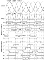
図4は、この発明の実施の形態1による車両用電力変換装置の動作を説明するタイミングチャートである。図4に於いて、U相正極側アームUHAに着目して説明すると、同期整流制御手段302は、同期整流許可手段301から出力された実施許可信号UHがHiレベルである時間、即ち、U相正極側アームUHAの寄生ダイオードがオン状態である時間TUH(n−1)を計測する。次に、同期整流制御手段302は、下記に示す式(1)で示すように、計測した寄生ダイオードのオン状態である時間TUH(n−1)から、制御の遅れ時間と発電電動機102の回転変動を考慮した制御余裕時間αとを差し引いた時間TUHon(n)を、U相正極側アームUHAが次回の同期整流を行う時のスイッチング素子UH223aのスイッチングタイミングとして演算し、この演算した時間TUHon(n)に応じた信号を出力信号UH*として出力し同期整流制御手段303へ入力する。
TUHon(n)=TUH(n−1)−α 式(1)
FIG. 4 is a timing chart for explaining the operation of the vehicle power converter according to
TUHon (n) = TUH (n−1) −α Formula (1)
同様に、U相負極側アームULA、V相正極側アームVHA、V相負極側アームVLA、W相正極側アームWHA、W相負極側アームWLAの各スイッチング素子UL224a、VH223b、VL224b、WH223c、WL224cのオン状態となる時間TULon(n)、TVHon(n)、TVLon(n)、TWHon(n)、TWLon(n)を、同期整流許可手段301の出力である実施許可信号UL、VH、VL、WH、WLから、夫々独立して、各相の前回の寄生ダイオードのオン状態の時間から制御の遅れ時間と発電電動機の回転変動を考慮した制御余裕時間αを減算するよう演算し、この演算した時間TULon(n)、TVHon(n)、TVLon(n)、TWHon(n)、TWLon(n)に応じた信号を夫々出力信号UL*、VH*、VL*、WH*、WL*として出力して同期整流制御手段303へ入力する。
Similarly, the switching elements UL224a, VH223b, VL224b, WH223c, WL224c of the U-phase negative side arm ULA, the V-phase positive side arm VHA, the V-phase negative side arm VLA, the W-phase positive side arm WHA, and the W-phase negative side arm WLA. The time TULon (n), TVHon (n), TVLon (n), TWHon (n), and TWLon (n) when the ON state is turned into the execution permission signals UL, VH, VL, which are outputs of the synchronous
同期整流手段303は、同期整流制御手段302の出力信号UH*、UL*、VH*、VL*、WH*、WL*に基づき、電力変換部220の各々対応するスイッチング素子UH223aと、VH223bと、WH223c、及びUL224aと、VL224bと、WL224cのゲート指令信号UHG、VHG、WHG、ULG、VLG、WLGを生成し、これらのスイッチング素子のゲートに入力する。
The
電力変換部220では、同期整流手段303からのゲート指令信号UHG、VHG、WHG、ULG、VLG、WLGに基づき、スイッチング素子UH223aと、VH223bと、WH223c、及びUL224aと、VL224bと、WL224cがオン、オフ制御され、夫々の寄生ダイオードのオンタイミングに同期したスイッチング動作を行い、同期整流を実行する。
In the
前述のように、この発明の実施の形態1による車両用電力変換装置によれば、三相ブリッジ回路の全相の正極側アームUHA、VHA、WHA、及び負極側アームULA、VLA、WLA毎に独立してスイッチングを行うことで、全相の正極側アーム及び負極側アーム毎に夫々最適なオン時間でスイッチング素子の制御を行うことが可能となり、高効率且つノイズに強く安定した発電力を供給できる車両用電力変換装置を提供することが可能である。 As described above, according to the vehicle power conversion device according to the first embodiment of the present invention, the positive-phase arms UHA, VHA, WHA and the negative-side arms ULA, VLA, WLA of all phases of the three-phase bridge circuit By switching independently, it becomes possible to control the switching element with the optimal on-time for each positive-phase arm and negative-side arm of all phases, and supply stable power generation with high efficiency and noise resistance. It is possible to provide a vehicular power conversion device.
実施の形態2.
次にこの発明の実施の形態2に係る車両用電力変換装置ついて説明する。実施の形態2は、実施の形態1に対してスイッチング素子のスイッチングタイミングの演算方法を変更したものであり、その他については実施の形態1と同様である。
Next, a vehicle power converter according to
図5は、この発明の実施の形態2に係る車両用電力変換装置の動作を説明するタイミングチャートである。同期整流制御手段302は、実施の形態1の場合と同様に、同期整流許可手段301の出力である実施許可信号UH、UL、VH、VL、WH、WLを入力し、全相の正極側アームUHA、VHA、WHA、及び負極側アームULA、VLA、WLAの夫々の寄生ダイオードのオン状態の時間をマイコン304の機能により計測する。次に、同期整流制御手段302は、全相の正極側アームUHA、VHA、WHA、及び負極側アームULA、VLA、WLAの計測した前回のダイオードのオン状態であるオン時間のうちから、最小のオン時間を選択し、この選択した最小のオン時間から、制御の遅れ時間と発電電動機の回転変動を考慮した制御余裕時間αを差し引いて、スイッチング素子UH223a、VH223b、WH223c、UL224a、VL224b、WL224cをオン状態とする時間、即ちスイッチングタイミングを演算し、その演算した時間に応じた信号を出力信号UH*、UL*、VH*、VL*、WH*、WL*として出力し同期整流手段303へ入力する。
FIG. 5 is a timing chart for explaining the operation of the vehicle power converter according to
図5に於いて、U相負極側アームULAに着目し、同期整流制御手段302が次回の同期整流を行う時のスイッチング素子224aのオン状態の時間Tmin1を出力信号UL*として出力する場合を説明する。この場合、図5から明らかなように、同期整流制御手
段302が次回のオン時間Tmin1を出力信号UL*として出力するときに、同期整流
許可手段301の出力である実施許可信号UH、UL、VH、VL、WH、WLから、前回の寄生ダイオードのオン状態の時間が既に計測できている値は、実施許可信号UHであればTUH(n−1)、実施許可信号ULであればTUL(n−2)(図示せず)、実施許可信号VHであればTVH(n−2)(図示せず)、実施許可信号VLであればTVL(n−1)、実施許可信号WHであればTWH(n−1)、実施許可信号WLであればTWL(n−2)(図示せず)である。
In FIG. 5, focusing on the U-phase negative electrode side arm ULA, the case where the on-time Tmin1 of the
この既に計測ができているオン時間のうちから最小のオン時間を選択し、下記の式(2)により、この選択した前回の実施許可信号の最小の時間から、制御の遅れ時間と発電電動機の回転変動を考慮した制御余裕時間αを差し引いた時間Tmin1を、U相下側アームのスイッチング素子224aの次回のオン状態の時間、即ちスイッチングタイミングとして出力する。
Tmin1=min[TUH(n−1)、TUL(n−2)、TVH(n−2)、
TVL(n−1)、TWH(n−1)、TWL(n−2)]−α 式(2)
The minimum on-time is selected from the on-times that have already been measured, and the control delay time and the generator motor are determined from the minimum time of the selected previous execution permission signal by the following equation (2). The time Tmin1 obtained by subtracting the control allowance time α in consideration of the rotational fluctuation is output as the next ON state time of the
Tmin1 = min [TUH (n-1), TUL (n-2), TVH (n-2),
TVL (n−1), TWH (n−1), TWL (n−2)] − α Formula (2)
同様に、次のスイッチングタイミングであるW相正極側アームWHAのTmin2では、同期整流許可手段301の出力である実施許可信号のオン状態の時間の計測が既にできている値は、実施許可信号UHであればTUH(n−1)、実施許可信号ULであればTUL(n−2)(図示せず)、実施許可信号VHであればTVH(n−2)(図示せず)、実施許可信号VLであればTVL(n−1)、実施許可信号WHであればTWH(n−1)、実施許可信号WLであればTWL(n−1)であり、これら実施許可信号のうちの最小時間を選択し、この最小のオン時間から、制御の遅れ時間と発電電動機の回転変動を考慮した制御余裕時間αを差し引いた時間Tmin2を、W相正極側アームWHAのスイッチング素子224cのスイッチングタイミングとして出力すればよい。
Similarly, at Tmin2 of the W-phase positive electrode side arm WHA that is the next switching timing, the value that has already been measured for the on-state time of the execution permission signal that is the output of the synchronous rectification permission means 301 is the execution permission signal UH. Is TUH (n-1), if it is an execution permission signal UL, TUL (n-2) (not shown), if it is the execution permission signal VH, TVH (n-2) (not shown), execution permission The signal VL is TVL (n-1), the execution permission signal WH is TWH (n-1), and the execution permission signal WL is TWL (n-1). The time Tmin2 obtained by subtracting the control delay time α in consideration of the control delay time and the rotation fluctuation of the generator motor from the minimum on-time is selected as the switch of the
同様にして、全相正極側アームUHA、VHA、WHA、及び負極側アームULA、VLA、WLAのスッチング素子のスイッチングの順に、各スイッチング素子のオンとなる時間であるスイッチングタイミングを、前回の実施許可信号のうちの最小時間から制御の遅れ時間と発電電動機の回転変動を考慮した制御余裕時間αを減算するように演算し、夫々のスイッチングタイミングに応じた信号を出力し同期整流制御手段303へ入力する。 In the same manner, the previous implementation permission is granted for the switching timing, which is the time when each switching element is turned on, in the order of switching of the switching elements of all-phase positive-side arms UHA, VHA, WHA and negative-side arms ULA, VLA, WLA. The control delay time α taking into account the control delay time and the generator motor rotation fluctuation is subtracted from the minimum time of the signal, and a signal corresponding to each switching timing is output and input to the synchronous rectification control means 303. To do.
同期整流手段303は、同期整流制御手段302の出力信号UH*、UL*、VH*、VL*、WH*、WL*に基づき、電力変換部220の各々対応するスイッチング素子UH223aと、VH223bと、WH223c、及びUL224aと、VL224bと、WL224cのゲート指令信号UHG、VHG、WHG、ULG、VLG、WLGを生成し、これらの対応するスイッチング素子のゲートに入力する。
The
電力変換部220では、同期整流手段303の出力であるゲート指令信号UHG、VHG、WHG、ULG、VLG、WLGに基づき、各スイッチング素子UH223a、VH
223b、WH223c、及びUL224a、VL224b、WL224cをスイッチン
グ制御することで寄生ダイオードのオンタイミングに同期したスイッチングを行い、同期整流を実行する。
In the
By performing switching control of 223b, WH223c, and
以上述べたこの発明の実施の形態2による車両用電力変換装置によれば、全相の正極側アーム及び負極側アームの実施許可信号のうちから最小時間を選択し、その選択した最小のオン時間から、制御の遅れ時間と発電電動機の回転変動を考慮した制御余裕時間αを差し引いた時間によりスイッチング素子をスイッチングを行うことで、スイッチングのオン状態が寄生ダイオードのオンタイミングに同期し、更にオンタイミングの範囲内でスイッチングすることが可能であり、寄生ダイオードのオンタイミングを逃すことなく最適なスイッチング制御を行うことが可能となり、高効率且つノイズに強く安定した車両用電力変換装置を提供することが可能である。 According to the above-described vehicle power conversion device according to the second embodiment of the present invention, the minimum time is selected from the execution permission signals of the positive-side arm and the negative-side arm of all phases, and the selected minimum on-time The switching ON state is synchronized with the ON timing of the parasitic diode by switching the switching element by the time obtained by subtracting the control delay time α taking into account the control delay time and the rotation fluctuation of the generator motor. It is possible to perform switching within the above range, and it is possible to perform optimum switching control without missing the on-timing of the parasitic diode, and to provide a highly efficient, noise-resistant and stable power conversion device for vehicles. Is possible.
実施の形態3.
次にこの発明の実施の形態3に係る車両用電力変換装置ついて説明する。実施の形態3は、実施の形態1及び2に対してスイッチング素子のスイッチングタイミングの演算方法を変更したものであり、その他については実施の形態1及び2と同様である。
Embodiment 3 FIG.
Next, a vehicle power converter according to Embodiment 3 of the present invention will be described. The third embodiment is different from the first and second embodiments in the method of calculating the switching timing of the switching element, and is otherwise the same as the first and second embodiments.
図6は、この発明の実施の形態3に係る車両用電力変換装置の動作を説明するタイミングチャートである。同期整流制御手段302は、実施の形態1の場合と同様に、同期整流許可手段301の出力である実施許可信号UH、UL、VH、VL、WH、WLを入力し、全相の正極側アーム及び負極側アームの夫々の寄生ダイオードのオン状態の時間をマイコン304の機能により計測する。次に、同期整流制御手段302は、全相の正極側アームUHA、VHA、WHA、及び負極側アームULA、VLA、WLAの計測した前回のダイオードのオン状態である時間の平均値を演算し、この平均値から制御の遅れ時間と発電電動機の回転変動を考慮した制御余裕時間を差し引いて、スイッチング素子UH223a、VH223b、WH223c、UL224a、VL224b、WL224cをオン状態とする時間、即ちスイッチングタイミングを演算し、この演算した夫々の時間に応じた信号を、同期整流手段303へ出力信号UH*、UL*、VH*、VL*、WH*、WL*として出力する。
FIG. 6 is a timing chart for explaining the operation of the vehicle power converter according to Embodiment 3 of the present invention. As in the case of the first embodiment, the synchronous
図6に於いて、U相負極側アームULAに着目し、同期整流制御手段302が次回の同期整流を行う時のスイッチング素子224aのオン状態の時間Tave1に応じた信号を出力信号UL*として出力する場合を説明する。時間Tave1に応じた信号が同期整流
制御手段302の出力信号UL*として出力されるときに、同期整流許可手段301の出
力である実施許可信号から寄生ダイオードのオン状態の時間を計測できている値は、UHであればTUH(n−1)、ULであればTUL(n−2)(図示せず)、VHであればTVH(n−2)(図示せず)、VLであればTVL(n−1)、WHであればTWH(n−1)、WLであればTWL(n−2)(図示せず)である。同期整流制御手段302は、下記の式(3)に示すように、計測した実施許可信号の平均時間を演算し、この演算した前回の実施許可信号の平均時間から、制御の遅れ時間と発電電動機の回転変動を考慮した制御余裕時間αを差し引いた時間Tave1を、U相負極側アームULAのスイッチング素子224aのスイッチングタイミングとして出力する。
Tave1={[TUH(n−1)、TUL(n−2)、TVH(n−2)、TVL(n−1)、 TWH(n−1)、TWL(n−2)]/6}−α 式(3)
In FIG. 6, paying attention to the U-phase negative arm ULA, a signal corresponding to the on-state time Tave1 of the
Tave1 = {[[TUH (n-1), TUL (n-2), TVH (n-2), TVL (n-1), TWH (n-1), TWL (n-2)] / 6}- α Formula (3)
同様に、次にスイッチングするW相正極側アームWLAのTave2では、同期整流許
可手段301の出力である実施許可信号のオン状態の時間を計測できている値は、UHであればTUH(n−1)、ULであればTUL(n−2)(図示せず)、VHであればTVH(n−2)(図示せず)、VLであればTVL(n−1)、WHであればTWH(n−1)、WLであればTWL(n−1)であり、これら実施許可信号の平均時間を演算し、その平均時間から、制御の遅れ時間と発電電動機の回転変動を考慮した制御余裕時間αを差し引いた時間Tave2に応じた信号を、W相正極側アームWHAのスイッチング素子224cのスイッチングタイミングとして出力すればよい。
Similarly, in the Tave2 of the W-phase positive electrode side arm WLA to be switched next, the value that can measure the ON state time of the execution permission signal that is the output of the synchronous
同様にして、全相正極側アームUHA、VHA、WHA、及び負極側アームULA、VLA、WLAのスッチング素子のスイッチングの順に、各スイッチング素子のオンとなる時間、即ちスイッチングタイミングを、前回の実施許可信号の平均時間から、制御の遅れ時間と発電電動機の回転変動を考慮した制御余裕時間αを差し引いて求め、その夫々の時間に応じた信号を出力信号として同期整流制御手段303へ出力する。 Similarly, in the order of switching of the switching elements of all-phase positive arm UHA, VHA, WHA and negative arm ULA, VLA, WLA, the time when each switching element is turned on, that is, the switching timing is permitted. A control delay time α in consideration of the control delay time and the rotation fluctuation of the generator motor is subtracted from the average signal time, and a signal corresponding to each time is output to the synchronous rectification control means 303 as an output signal.
同期整流手段303は、同期整流制御手段302の出力信号UH*、UL*、VH*、VL*、WH*、WL*に基づき、電力変換部220の各々対応するスイッチング素子UH223aと、VH223bと、WH223c、及びUL224aと、VL224bと、WL224cのゲート指令信号UHG、VHG、WHG、ULG、VLG、WLGを生成し、これらの対応するスイッチング素子のゲートに入力する。
The
電力変換部220では、同期整流手段303の出力であるゲート指令信号UHG、VHG、WHG、ULG、VLG、WLGに基づき、各スイッチング素子UH223a、VH
223b、WH223c、及びUL224a、VL224b、WL224cをスイッチン
グ制御することで寄生ダイオードのオンタイミングに同期したスイッチングを行い、同期整流を実行する。
In the
By performing switching control of 223b, WH223c, and
以上述べたこの発明の実施の形態3による車両用電力変換装置によれば、全相の正極側アーム及び負極側アームの実施許可信号の平均時間を演算し、その平均時間から、制御の遅れ時間と発電電動機の回転変動を考慮した制御余裕時間αを差し引いた時間によりスイッチング素子をスイッチングを行うことで、同期整流の実施許可信号にオン状態の時間にバラツキがあっても、オン状態の平均時間を演算することで寄生ダイオードのオンタイミングに同期し、更にオンタイミングの範囲内でスイッチングすることが可能であり、寄生ダイオードのオンタイミングを逃すことなく最適なスイッチング制御を行うことが可能となり、高効率且つノイズに強く安定した車両用電力変換装置を提供することが可能である。 According to the vehicular power conversion device according to the third embodiment of the present invention described above, the average time of the execution permission signals of the positive side arm and the negative side arm of all phases is calculated, and the control delay time is calculated from the average time. The switching element is switched according to the time obtained by subtracting the control margin time α taking into account the rotational fluctuation of the generator motor, so that even if there is a variation in the ON state time of the synchronous rectification execution permission signal, the average time of the ON state Can be synchronized with the on-timing of the parasitic diode, and can be switched within the on-timing range, enabling optimal switching control without missing the on-timing of the parasitic diode. It is possible to provide a vehicular power conversion device that is efficient and resistant to noise.
実施の形態4.
次にこの発明の実施の形態4に係る車両用電力変換装置ついて説明する。実施の形態4は、実施の形態1乃至3に対してスイッチング素子のスイッチングタイミングの演算方法を変更したものであり、その他については実施の形態1乃至3と同様である。
Embodiment 4 FIG.
Next, a vehicle power converter according to Embodiment 4 of the present invention will be described. The fourth embodiment is different from the first to third embodiments in the method of calculating the switching timing of the switching element, and is otherwise the same as the first to third embodiments.
図7は、この発明の実施の形態4に係る車両用電力変換装置の動作を説明するタイミングチャートである。同期整流制御手段302では、同期整流許可手段301の出力である実施許可信号を入力し、各寄生ダイオードのオン状態の時間をマイコン304の機能により計測する。同期整流制御手段302は、全相の正極側アームの計測した前回の寄生ダイオードのオン状態の時間のうちの最小時間、及び全相の負極側アームの計測した前回の寄生ダイオードのオン状態の時間のうちの最小時間を選択し、正極側アーム及び負極側アーム夫々の寄生ダイオードのオン状態の最小時間から、制御の遅れ時間と発電電動機の回転変動を考慮した制御余裕時間αを差し引いて、スイッチング素子UH223a、VH223b、WH223c、UL224a、VL224b、WL224cをオン状態とする時間、即ちスイッチングタイミングを演算し、この演算した夫々の時間に応じた信号を出力信号UH*、UL*、VH*、VL*、WH*、WL*として出力し、同期整流手段303へ入力する。
FIG. 7 is a timing chart for explaining the operation of the vehicle power converter according to Embodiment 4 of the present invention. The synchronous
図7に於いて、U相負極側アームULAに着目し、同期整流制御手段302が次回の同期整流を行う時のスイッチング素子224aのオン状態の時間TL1に応じた信号を出力
信号UL*として出力する場合を説明する。同期整流制御手段302が出力信号UL*としてTL1を出力するときに、各相の負極側アームで同期整流許可手段301の出力である実施許可信号のオン状態の時間を計測できている値は、ULであればTUL(n−2)(図示せず)、VLであればTVL(n−1)、WLであればTWL(n−2)(図示せず)である。この計測した実施許可信号のうちの最小時間を選択し、下記の式(4)に示すように、その実施許可信号の最小時間から、制御の遅れ時間と発電電動機の回転変動を考慮した制御余裕時間αを差し引いた時間Tmin1を、U相負極側アームULAのスイッチング素子224aのスイッチングタイミングとして出力する。
TL1=min[TUL(n−2)、TVL(n−1)、TWL(n−2)]−α
式(4)
In FIG. 7, paying attention to the U-phase negative electrode side arm ULA, a signal corresponding to the time TL 1 when the
TL 1 = min [TUL (n−2), TVL (n−1), TWL (n−2)] − α
Formula (4)
このようにして、全相負極側アームのスイッチングの順に負極側アームの各スイッチング素子のスイッチングタイミングを、前回の全相負極側の実施許可信号のうちの最小時間から、制御の遅れ時間と発電電動機の回転変動を考慮した制御余裕時間αを差し引いて求め、その求めた時間に応じた信号を同期整流制御手段303へ入力する。 In this way, the switching timing of each switching element of the negative electrode side arm in the order of switching of the negative phase arm of the all phase is changed from the minimum time of the previous execution permission signals of the negative phase side of the all phase to the control delay time and the generator motor. The control margin time α taking into account the rotational fluctuation is subtracted and a signal corresponding to the obtained time is input to the synchronous rectification control means 303.
一方、U相正極側アームUHAのオン状態の時間TU1は、同期整流許可手段301の出力である実施許可信号のオン状態の時間を計測できている値は、UHであればTUH(n−1)、VHであればTVH(n−1)、WHであればTWH(n−1)であり、これらの中でのオン状態の最小時間を選択し、下記の式(5)に示すように、その選択した最小時間から、制御の遅れ時間と発電電動機の回転変動を考慮した制御余裕時間αを差し引いた時間TU1を、U相正極側アームUHAのスイッチング素子223aのスイッチングタイミングとして出力すればよい。
TU1=min[TUH(n−1)、TVH(n−1)、TWH(n−1)]−α
式(5)
On the other hand, the on-state time TU 1 of the U-phase positive electrode side arm UHA is TUH (n− if the value that can measure the on-state time of the execution permission signal that is the output of the synchronous
TU 1 = min [TUH (n−1), TVH (n−1), TWH (n−1)] − α
Formula (5)
このようにして、全相正極側アームのスイッチングの順に正極側アームの各スイッチング素子のスイッチングタイミングを、前回の全相の正極側実施許可信号のうちの最小時間から、制御の遅れ時間と発電電動機の回転変動を考慮した制御余裕時間αを差し引いて求め、その求めた時間に応じた信号を同期整流制御手段303へ入力する。 In this way, the switching timing of each switching element of the positive side arm is changed from the minimum time of the positive side execution permission signals of all previous phases to the control delay time and the generator motor. The control margin time α taking into account the rotational fluctuation is subtracted and a signal corresponding to the obtained time is input to the synchronous rectification control means 303.
同期整流手段303は、同期整流制御手段302の出力信号UH*、UL*、VH*、VL*、WH*、WL*に基づき、電力変換部220の各々対応するスイッチング素子UH223aと、VH223bと、WH223c、及びUL224aと、VL224bと、WL224cのゲート指令信号UHG、VHG、WHG、ULG、VLG、WLGを生成し、これらの対応するスイッチング素子のゲートに入力する。
The
電力変換部220では、同期整流手段303の出力であるゲート指令信号UHG、VHG、WHG、ULG、VLG、WLGに基づき、各スイッチング素子UH223a、VH
223b、WH223c、及びUL224a、VL224b、WL224cをスイッチン
グ制御することで寄生ダイオードのオンタイミングに同期したスイッチングを行い、同期整流を実行する。
In the
By performing switching control of 223b, WH223c, and
以上述べたこの発明の実施の形態4による車両用電力変換装置によれば、全相正極側アーム及び負極側アームの実施許可信号の最小時間を正極側アームと負極側アーム毎に演算し、その最小時間から、制御の遅れ時間と発電電動機の回転変動を考慮した制御余裕時間αを差し引いた時間によりスイッチング素子をスイッチングを行うことで、スイッチングのオン状態が寄生ダイオードのオンタイミングに同期し、正極側アーム及び負極側アーム毎に最小時間でスイッチング素子をオンするので、各相正極側アーム及び負極側アームの適切なオンタイミングの範囲でスイッチングすることが可能であり、寄生ダイオードのオンタイミングを逃すことなく最適なスイッチング制御を行うことが可能となり、高効率な且つノイズに強く安定した車両用電力変換装置を提供することが可能である。 According to the vehicle power conversion device according to Embodiment 4 of the present invention described above, the minimum time of the execution permission signal of the all-phase positive side arm and the negative side arm is calculated for each positive side arm and negative side arm, By switching the switching element by the time obtained by subtracting the control delay time α taking into account the control delay time and the generator motor rotation fluctuation from the minimum time, the switching ON state is synchronized with the parasitic diode ON timing, and the positive electrode Since the switching element is turned on in the minimum time for each of the side arm and the negative side arm, it is possible to switch within the appropriate on timing range of each phase positive side arm and negative side arm, and miss the on-timing of the parasitic diode. It is possible to perform optimal switching control without any problem, and it is a highly efficient, noise-resistant and stable vehicle It is possible to provide a power conversion device.
実施の形態5.
次にこの発明の実施の形態5に係る車両用電力変換装置ついて説明する。実施の形態5は、実施の形態1乃至4に対してスイッチング素子のスイッチングタイミングの演算方法を変更したものであり、その他については実施の形態1乃至4と同様である。前述の実施の形態4では、同期整流許可手段301の出力である実施許可時間の正極側アームと負極側アーム毎に、夫々最小時間を選択しその最小時間に基づいて正極側アームと負極側アーム毎の同期整流制御手段302の出力信号を得ていたが、実施形態5では、同期整流許可手段301の出力である実施許可時間の正極側アームと負極側アーム毎に、夫々の平均時間を演算して同期整流制御手段302の出力とするものである。
Next, a vehicle power converter according to
そして、全相正極側アームUHA、VHA、WHA、及び負極側アームULA、VLA、WLA毎のスッチング素子のスイッチングの順に、各スイッチング素子のオンとなる時間、即ちスイッチングタイミングを、前回の実施許可信号の平均時間から、制御の遅れ時間と発電電動機の回転変動を考慮した制御余裕時間αを差し引いて求め、夫々の時間に応じた信号を出力信号として同期整流制御手段303へ出力する。 Then, in the order of switching of the switching elements for all phase positive side arms UHA, VHA, WHA and negative side arms ULA, VLA, WLA, the time when each switching element is turned on, that is, the switching timing, is set as the previous execution permission signal. The control delay time α taking into account the control delay time and the rotational fluctuation of the generator motor is subtracted from the average time, and a signal corresponding to each time is output to the synchronous rectification control means 303 as an output signal.
同期整流手段303は、同期整流制御手段302の出力信号UH*、UL*、VH*、VL*、WH*、WL*に基づき、電力変換部220の各々対応するスイッチング素子UH223aと、VH223bと、WH223c、及びUL224aと、VL224bと、WL224cのゲート指令信号UHG、VHG、WHG、ULG、VLG、WLGを生成し、これらの対応するスイッチング素子のゲートに入力する。 The synchronous rectification means 303 is based on the output signals UH * , UL * , VH * , VL * , WH * , WL * of the synchronous rectification control means 302, the switching elements UH223a, VH223b, WH223c, UL224a, VL224b, and WL224c gate command signals UHG, VHG, WHG, ULG, VLG, and WLG are generated and input to the gates of the corresponding switching elements.
電力変換部220では、同期整流手段303の出力であるゲート指令信号UHG、VHG、WHG、ULG、VLG、WLGに基づき、各スイッチング素子UH223a、VH
223b、WH223c、及びUL224a、VL224b、WL224cをスイッチン
グ制御することで寄生ダイオードのオンタイミングに同期したスイッチングを行い、同期整流を実行する。
In the
By performing switching control of 223b, WH223c, and
以上述べたこの発明の実施の形態5による車両用電力変換装置によれば、全相正極側アーム及び負極側アームの実施許可信号の平均時間を正極側アームと負極側アーム毎に演算し、その平均時間から、制御の遅れ時間と発電電動機の回転変動を考慮した制御余裕時間αを差し引いた時間によりスイッチング素子のスイッチングを行うことで、スイッチングのオン状態が寄生ダイオードのオンタイミングに同期し、正極側アーム及び負極側アーム毎に平均時間でスイッチング素子をオンするので、各相正極側アーム及び負極側アームの適切なオンタイミングの範囲でスイッチングすることが可能であり、寄生ダイオードのオンタイミングを逃すことなく最適なスイッチング制御を行うことが可能となり、高効率な且つノイズに強く安定した車両用電力変換装置を提供することが可能である。
According to the vehicle power conversion device according to
実施の形態6.
次にこの発明の実施の形態6に係る車両用電力変換装置ついて説明する。実施の形態6は、実施の形態1乃至5に対して同期整流制御手段の出力であるスイッチング素子のスイッチングタイミングの演算方法を変更したものであり、他については実施の形態1乃至5と同様である。
Embodiment 6 FIG.
Next, a vehicle power converter according to Embodiment 6 of the present invention will be described. The sixth embodiment is different from the first to fifth embodiments in the method of calculating the switching timing of the switching element that is the output of the synchronous rectification control means, and is otherwise the same as the first to fifth embodiments. is there.
図8は、この発明の実施の形態6に係る車両用電力変換装置の動作を説明するタイミングチャートである。同期整流制御手段302では、同期整流許可手段301の出力である実施許可信号の何れか1つ以上を入力し、その入力した実施許可信号から対応する寄生ダイオードのオン状態の時間をマイコン304の機能にて計測する。何れか1つ以上入力した実施許可信号の計測したオン状態の時間から前回の寄生ダイオードのオン状態の時間の最小時間を選択し、その選択した実施許可信号の最小時間から、制御の遅れ時間と発電電動機の回転変動を考慮した制御余裕時間αを差し引き、スイッチング素子のスイッチングタイミングを演算し、同期整流手段303へ出力する。
FIG. 8 is a timing chart for explaining the operation of the vehicular power conversion apparatus according to the sixth embodiment of the present invention. In the synchronous
図8に於いて、V相正極側アームVHAに着目し、同期整流制御手段302が次回の同期整流を行う時のスイッチング素子224bのオン状態の時間T1に応じた信号を出力信
号VH*として出力する場合を説明する。以下の説明では、実施許可信号の何れか1つ以上の信号として、U相とV相とW相の正極側アームの実施許可信号UH、VH、WHを選択したと仮定して説明する。同期整流制御手段302の出力信号VH*としてT1を出力するときに、前述の選択した実施許可信号でオン状態の時間を計測できている値は、UHであればTUH(n−1)、VHであればTVH(n−1)、WHであればTWH(n)である。
In FIG. 8, paying attention to the V-phase positive side arm VHA, a signal corresponding to the on-time T 1 of the
この計測した実施許可信号のうちの最小時間を選択し、下記の式(6)に示すように、その最小時間から、制御の遅れ時間と発電電動機の回転変動を考慮した制御余裕時間αを差し引いた時間T1を、V相の正極側アームVHAのスイッチング素子223bのスイッ
チングタイミングとして出力する。
T1=min[TUH(n−1)、TVH(n−1)、TWH(n)]−α
式(6)
Select the minimum time from the measured execution permission signal, and subtract the control allowance time α taking into account the control delay time and the rotation fluctuation of the generator motor from the minimum time as shown in the following equation (6). The time T 1 is output as the switching timing of the
T 1 = min [TUH (n−1), TVH (n−1), TWH (n)] − α
Formula (6)
次にU相負極側アームULAのT2が出力されるが、T2を演算するには、選択した実施許可信号でオン状態の時間を計測できている値は、UHであればTUH(n)、VHであればTVH(n−1)、WHであればTWH(n)となり、これら実施許可信号のうちの最小時間を選択し、その最小時間から、制御の遅れ時間と発電電動機の回転変動を考慮した制御余裕時間αを差し引いた時間T2を、U相負極側アームULAのスイッチング素子224aのスイッチングタイミングとして出力すればよい。
Next, T 2 of the U-phase negative electrode side arm ULA is output. To calculate T 2 , if the value of the on-state time measured by the selected execution permission signal is UH, TUH (n ), VH is TVH (n-1), WH is TWH (n), and the minimum time is selected from these execution permission signals. From the minimum time, the control delay time and the generator motor rotation are selected. the time T 2 by subtracting the control allowance time α considering variation may be output as a switching timing of the
同様にして選択された実施許可信号のオン時間に基づき、全相の正極側アーム及び負極側アームのスイッチングの順に各スイッチング素子のスイッチングタイミングを、前回の実施許可信号の最小時間から、制御の遅れ時間と発電電動機の回転変動を考慮した制御余裕時間αを差し引いて求め、同期整流制御手段303へ出力する。 Similarly, based on the ON time of the execution permission signal selected in the same manner, the switching timing of each switching element is changed from the minimum time of the previous execution permission signal in the order of switching of the positive side arm and the negative side arm of all phases. It is obtained by subtracting the control margin time α in consideration of the time and the rotational fluctuation of the generator motor, and output to the synchronous rectification control means 303.
同期整流手段303は、同期整流制御手段302の出力信号UH*、UL*、VH*、VL*、WH*、WL*に基づき、電力変換部220の各々対応するスイッチング素子UH223aと、VH223bと、WH223c、及びUL224aと、VL224bと、WL224cのゲート指令信号UHG、VHG、WHG、ULG、VLG、WLGを生成し、これらの対応するスイッチング素子のゲートに入力する。
The
電力変換部220では、同期整流手段303の出力であるゲート指令信号UHG、VHG、WHG、ULG、VLG、WLGに基づき、各スイッチング素子UH223a、VH
223b、WH223c、及びUL224a、VL224b、WL224cをスイッチン
グ制御することで寄生ダイオードのオンタイミングに同期したスイッチングを行い、同期整流を実行する。
In the
By performing switching control of 223b, WH223c, and
以上述べたこの発明の実施の形態6による車両用電力変換装置によれば、全相の正極側アーム及び負極側アームの実施許可信号を何れか1つ以上選択しそのうちの最小時間を演算し、その最小時間から、制御の遅れ時間と発電電動機の回転変動を考慮した制御余裕時間αを差し引いた時間によりスイッチング素子をスイッチングを行うことで、スイッチングのオン状態が寄生ダイオードのオンタイミングに同期し、最小時間でスイッチング素子をオンするので、各相正極側アーム及び負極側アームのオンタイミングの範囲内でスイッチングすることが可能であり、寄生ダイオードのオンタイミングを逃すことなく最適なスイッチング制御を行うことが可能となり、高効率且つノイズに強く安定した車両用電力変換装置を提供することが可能である。また、実施許可時間を選択することにより、マイコン304の負荷軽減にもつながる。
According to the vehicle power conversion device according to Embodiment 6 of the present invention described above, any one or more of the implementation permission signals for the positive-phase arm and the negative-side arm of all phases are selected, and the minimum time is calculated. By switching the switching element by the time obtained by subtracting the control delay time α taking into account the control delay time and the rotation fluctuation of the generator motor from the minimum time, the ON state of the switching is synchronized with the ON timing of the parasitic diode, Since the switching element is turned on in the minimum time, it is possible to switch within the range of the on-timing of each phase positive-side arm and negative-side arm, and optimal switching control is performed without missing the on-timing of the parasitic diode It is possible to provide a highly efficient, noise-resistant and stable power converter for vehicles. . Further, by selecting the execution permission time, the load on the
実施の形態7.
次にこの発明の実施の形態7に係る車両用電力変換装置ついて説明する。実施の形態7は、実施の形態1乃至6に対してスイッチング素子のスイッチングタイミングの演算方法を変更したものであり、その他については実施の形態1乃至6と同様である。前述の実施の形態6では、同期整流許可手段301の出力である実施許可信号から何れか1つ以上を選択しそのうちの最小時間に基づいて同期整流制御手段302の出力信号を得るようにしていたが、実施の形態7では、選択した実施許可信号の平均時間を演算し、その平均時間に基づいて同期整流制御手段302の出力信号を得るようにしたものである。
Embodiment 7 FIG.
Next, a vehicle power converter according to Embodiment 7 of the present invention will be described. The seventh embodiment is different from the first to sixth embodiments in the method of calculating the switching timing of the switching element, and is otherwise the same as the first to sixth embodiments. In the above-described sixth embodiment, one or more of the execution permission signals that are the output of the synchronous rectification permission means 301 are selected, and the output signal of the synchronous rectification control means 302 is obtained based on the minimum time among them. However, in the seventh embodiment, the average time of the selected execution permission signal is calculated, and the output signal of the synchronous rectification control means 302 is obtained based on the average time.
そして、全相正極側アームと負極側アームのスッチング素子のスイッチングの順に、各スイッチング素子のオンとなる時間、即ちスイッチングタイミングを、前回の実施許可信号の平均時間から、制御の遅れ時間と発電電動機の回転変動を考慮した制御余裕時間αを差し引いて求め、夫々の時間に応じた信号を出力信号として同期整流制御手段303へ出力する。 Then, in the order of switching of the switching elements of all-phase positive side arm and negative side arm, the time when each switching element is turned on, that is, the switching timing is changed from the average time of the previous execution permission signal to the control delay time and the generator motor. The control margin time α in consideration of the rotational fluctuation is subtracted and a signal corresponding to each time is output to the synchronous rectification control means 303 as an output signal.
同期整流手段303は、同期整流制御手段302の出力信号UH*、UL*、VH*、VL*、WH*、WL*に基づき、電力変換部220の各々対応するスイッチング素子UH223aと、VH223bと、WH223c、及びUL224aと、VL224bと、WL224cのゲート指令信号UHG、VHG、WHG、ULG、VLG、WLGを生成し、これらの対応するスイッチング素子のゲートに入力する。
The
電力変換部220では、同期整流手段303の出力であるゲート指令信号UHG、VHG、WHG、ULG、VLG、WLGに基づき、各スイッチング素子UH223a、VH
223b、WH223c、及びUL224a、VL224b、WL224cをスイッチン
グ制御することで寄生ダイオードのオンタイミングに同期したスイッチングを行い、同期整流を実行する。
In the
By performing switching control of 223b, WH223c, and
以上述べたこの発明の実施の形態7による車両用電力変換装置によれば、全相の正極側アーム及び負極側アームの実施許可信号を何れか1つ以上選択しその平均時間を演算し、
その平均時間から、制御の遅れ時間と発電電動機の回転変動を考慮した制御余裕時間αを差し引いた時間によりスイッチング素子をスイッチングを行うことで、スイッチングのオン状態が寄生ダイオードのオンタイミングに同期し、平均時間でスイッチング素子をオンするので、各相正極側アーム及び負極側アームの適切なオンタイミングの範囲でスイッチングすることが可能であり、寄生ダイオードのオンタイミングを逃すことなく最適なスイッチング制御を行うことが可能となり、高効率な且つノイズに強く安定した車両用電力変換装置を提供することが可能である。
According to the vehicle power conversion device according to Embodiment 7 of the present invention described above, any one or more of the implementation permission signals for the positive-phase arm and the negative-side arm of all phases are selected, and the average time is calculated.
By switching the switching element by the time obtained by subtracting the control delay time α taking into account the control delay time and the rotation fluctuation of the generator motor from the average time, the on-state of switching is synchronized with the on-timing of the parasitic diode, Since the switching element is turned on in an average time, it is possible to perform switching within the appropriate on-timing range of each phase positive-side arm and negative-side arm, and optimal switching control is performed without missing the on-timing of the parasitic diode. Therefore, it is possible to provide a vehicle power conversion device that is highly efficient and stable against noise.
実施の形態8.
次にこの発明の実施の形態8に係る車両用電力変換装置ついて説明する。これまで実施の形態1から7では同期整流許可手段301の出力である実施許可信号のオン状態の時間を計測していた。しかし、図9のタイミングチャートに示すように、何らかの要因により同期整流許可手段301の出力の周期が所定値と異なった場合、同期整流制御手段301は正常な出力をすることができなくなり、安定した発電電力を供給することができなくなる。
Embodiment 8 FIG.
Next, a vehicle power converter according to Embodiment 8 of the present invention will be described. So far, in the first to seventh embodiments, the ON state time of the execution permission signal that is the output of the synchronous
そこで、実施の形態8では、実施許可信号のうちの少なくとも1つのオン状態の時間が所定値より小さいか否かを判断し、所定値より大きい場合は通常通り実施の形態1乃至7の何れかの動作を行う。実施許可信号のうちの少なくとも1つが所定値より小さい場合は、同期整流制御手段301の出力を停止させる。前述の判断を行なうための所定値は、例えば通電幅TOFFWidthを90度とした場合、所定時間TOFF[sec]は、発電電動機の電気回転速度NmGe[rpm]から演算することができ、下記の式(7)により表すことができる。
TOFF=TOFFWidth/Nmge 式(7)
Therefore, in the eighth embodiment, it is determined whether or not the on-state time of at least one of the execution permission signals is smaller than a predetermined value. If it is larger than the predetermined value, any one of the first to seventh embodiments is performed as usual. Perform the operation. When at least one of the execution permission signals is smaller than the predetermined value, the output of the synchronous
T OFF = T OFF Width / Nmg equation (7)
上記より、演算された所定時間より同期整流許可手段の出力である実施許可信号のうち少なくとも1つが小さい場合に、同期整流制御手段301の出力をオフ状態にし、同期整流を停止し、寄生ダイオードにより整流を行う。尚、実施許可時間が所定時間より小さいものが1つ以上の場合も同様であるのは勿論である。 From the above, when at least one of the execution permission signals that are the output of the synchronous rectification permission means is smaller than the calculated predetermined time, the output of the synchronous rectification control means 301 is turned off, the synchronous rectification is stopped, and the parasitic diode Rectify. It goes without saying that the same applies to the case where the number of execution permission times is smaller than the predetermined time.
尚、実施の形態8では、実施許可信号のうちの少なくとも1つが所定時間より小さい場合に同期整流制御手段が同期整流をオフ状態にするようにしたが、所定時間より大きい場合に同期整流制御手段が同期整流をオフ状態にするようにしてもよい。 In the eighth embodiment, the synchronous rectification control means turns off the synchronous rectification when at least one of the execution permission signals is smaller than the predetermined time. May turn off synchronous rectification.
以上述べたこの発明の実施の形態8による車両用電力変換装置によれば、同期整流許可手段の出力である実施許可信号のうちの少なくとも1つの周期が所定値と異なるときに同期整流制御手段が同期整流をオフ状態にすることにより、同期整流のオン、オフ状態を繰り返すことがなくなり、安定した発電電力を供給することが可能である。 According to the above-described vehicular power conversion device according to the eighth embodiment of the present invention, the synchronous rectification control means is operated when at least one cycle of the execution permission signal that is the output of the synchronous rectification permission means is different from the predetermined value. By turning off the synchronous rectification, it is possible to supply stable generated power without repeating the on / off state of the synchronous rectification.
実施の形態9.
次にこの発明の実施の形態9に係る車両用電力変換装置ついて説明する。実施の形態9とこれまでの実施の形態1乃至8との差異は、マイコン304に同期整流停止手段307を設けたことである。
Embodiment 9 FIG.
Next, a vehicle power converter according to Embodiment 9 of the present invention will be described. The difference between the ninth embodiment and the first to eighth embodiments is that the
図10は、この発明の実施の形態9に係る車両用電力変換装置の構成を示すブロック図である。図10に於いて、同期整流停止手段307は、界磁電流検出手段306の出力である界磁電流値と、回転数検出手段305の出力である回転数Nmgeとが入力される。同期整流停止手段307は、同期整流が可能な界磁電流値と回転数Nmgeとの関係が示された回転数・界磁電流値のマップから、回転数Nmgeに応じた同期整流が可能な界磁電流を演算し、界磁電流検出手段306の出力と比較を行う。
FIG. 10 is a block diagram showing the configuration of the vehicle power converter according to Embodiment 9 of the present invention. In FIG. 10, the synchronous
尚、回転数・界磁電流値のマップは、予めROMに記憶しておいてもよい。又、マップの他に、回転数に対する界磁電流の演算式を用いてもよい。 The rotation speed / field current value map may be stored in the ROM in advance. In addition to the map, an arithmetic expression for the field current with respect to the rotational speed may be used.
同期整流停止手段307は、界磁電流検出手段306の出力である界磁電流Ifが界磁電流値マップから読み込んだ値より大きな場合は、同期整流停止信号を同期整流制御手段302へは出力せず、前述の実施の形態1乃至8の何れかの手法を用いて、同期整流許可手段301からの実施許可信号のオン時間を計測し、前述の各実施の形態で説明したようにして同期整流制御手段302の出力を演算し、スイッチング素子をオン状態をとするスイッチングタイミングを同期整流手段303に入力する。
The synchronous
同期整流手段303は、同期整流制御手段302の出力信号UH*、UL*、VH*、VL*、WH*、WL*に基づき、電力変換部220の各々対応するスイッチング素子UH223aと、VH223bと、WH223c、及びUL224aと、VL224bと、WL224cのゲート指令信号UHG、VHG、WHG、ULG、VLG、WLGを生成し、これらの対応するスイッチング素子のゲートに入力する。
The
電力変換部220では、同期整流手段303の出力であるゲート指令信号UHG、VHG、WHG、ULG、VLG、WLGに基づき、各スイッチング素子UH223a、VH
223b、WH223c、及びUL224a、VL224b、WL224cをスイッチン
グ制御することで寄生ダイオードのオンタイミングに同期したスイッチングを行い、同期整流を実行する。
In the
By performing switching control of 223b, WH223c, and
一方、同期整流停止手段307は、界磁電流値Ifが回転数検出手段305の検出した回転数に対応する界磁電流マップ値より小さい場合、同期整流許可手段301の出力である実施許可信号が許可状態であっても、同期整流制御手段302へ同期整流停止信号を出力する。同期整流制御手段302は、同期整流停止手段307からの同期整流停止信号に基づき、出力をオフ状態として同期整流を停止する。この場合、寄生ダイオードにより整流が行なわれる。
On the other hand, when the field current value If is smaller than the field current map value corresponding to the rotation speed detected by the rotation speed detection means 305, the synchronous rectification stop means 307 outputs the execution permission signal that is the output of the synchronous rectification permission means 301. Even in the permitted state, a synchronous rectification stop signal is output to the synchronous rectification control means 302. The synchronous
以上述べたこの発明の実施の形態9による車両用電力変換装置によれば、同期整流停止手段により、界磁電流の値に基づいて同期整流の実施、若しくは未実施を決定するようにしたので、界磁電流が所定値より小さなところでは同期整流のオン・オフ状態を繰り返すことがなく、安定した発電電力を供給することが可能となる。 According to the vehicle power conversion device according to the ninth embodiment of the present invention described above, the synchronous rectification stop means determines whether to perform synchronous rectification based on the value of the field current, or not. When the field current is smaller than a predetermined value, the synchronous rectification ON / OFF state is not repeated, and stable generated power can be supplied.
101 内燃機関
102 発電電動機
103 蓄電池
104 動力伝達手段
110 電力変換装置
200 モータジェネレータ部
201 電機子コイル
202 界磁コイル
210 制御装置
211 回転子位置検出部
212 ダイオード通電状態検出部
213 タイミング処理部
214 ゲート指令生成部
215 ゲート指令監視部
220 電力変換部
221 界磁スイッチング素子
222 フリーホイールダイオード
223a U相正極側アームスイッチング素子
223b V相正極側アームスイッチング素子
223c W相正極側アームスイッチング素子
224a U相負極側アームスイッチング素子
224b V相負極側アームスイッチング素子
224c W相負極側アームスイッチング素子
301 同期整流許可手段
302 同期整流制御手段
303 同期整流手段
304 マイコン
305 回転数検出手段
306 界磁電流検出手段
307 同期整流停止手段
DESCRIPTION OF
Claims (9)
Priority Applications (1)
| Application Number | Priority Date | Filing Date | Title |
|---|---|---|---|
| JP2008130966A JP4934097B2 (en) | 2008-05-19 | 2008-05-19 | Power converter for vehicle |
Applications Claiming Priority (1)
| Application Number | Priority Date | Filing Date | Title |
|---|---|---|---|
| JP2008130966A JP4934097B2 (en) | 2008-05-19 | 2008-05-19 | Power converter for vehicle |
Publications (2)
| Publication Number | Publication Date |
|---|---|
| JP2009284564A true JP2009284564A (en) | 2009-12-03 |
| JP4934097B2 JP4934097B2 (en) | 2012-05-16 |
Family
ID=41454426
Family Applications (1)
| Application Number | Title | Priority Date | Filing Date |
|---|---|---|---|
| JP2008130966A Active JP4934097B2 (en) | 2008-05-19 | 2008-05-19 | Power converter for vehicle |
Country Status (1)
| Country | Link |
|---|---|
| JP (1) | JP4934097B2 (en) |
Cited By (7)
| Publication number | Priority date | Publication date | Assignee | Title |
|---|---|---|---|---|
| JP2011166863A (en) * | 2010-02-05 | 2011-08-25 | Denso Corp | Generator for vehicles |
| FR2959073A1 (en) * | 2010-04-15 | 2011-10-21 | Mitsubishi Electric Corp | ELECTRIC POWER CONVERTER FOR VEHICLE |
| EP2403133A2 (en) | 2010-07-02 | 2012-01-04 | Mitsubishi Electric Corporation | Electric power converting apparatus |
| DE102011051756A1 (en) | 2010-07-16 | 2012-01-19 | Denso Corporation | Generator for vehicle e.g. passenger car, has timing determining unit displaying identification signal to control unit if differential voltage is maintained for preset time period, where differential voltage is higher than threshold voltage |
| JP2012503966A (en) * | 2008-09-25 | 2012-02-09 | ローベルト ボツシユ ゲゼルシヤフト ミツト ベシユレンクテル ハフツング | Synchronous rectifier drive control |
| JP2012070559A (en) * | 2010-09-24 | 2012-04-05 | Denso Corp | Rotary electric machine for vehicle |
| WO2021220632A1 (en) * | 2020-04-28 | 2021-11-04 | シャープ株式会社 | Rectifier device and contactless power supply system |
Citations (4)
| Publication number | Priority date | Publication date | Assignee | Title |
|---|---|---|---|---|
| JP2001320882A (en) * | 2000-05-09 | 2001-11-16 | Matsushita Electric Ind Co Ltd | Power supply apparatus, inverter and air conditioner |
| JP2003284396A (en) * | 2002-03-19 | 2003-10-03 | Toyota Motor Corp | Controller for alternating-current generator-motor |
| JP2004180427A (en) * | 2002-11-27 | 2004-06-24 | Mitsubishi Electric Corp | Regenerative power supply converter |
| JP2007209154A (en) * | 2006-02-03 | 2007-08-16 | Matsushita Electric Ind Co Ltd | Controller for brushless dc motor, heat-exchange type cooling device, and ventilator blower |
-
2008
- 2008-05-19 JP JP2008130966A patent/JP4934097B2/en active Active
Patent Citations (4)
| Publication number | Priority date | Publication date | Assignee | Title |
|---|---|---|---|---|
| JP2001320882A (en) * | 2000-05-09 | 2001-11-16 | Matsushita Electric Ind Co Ltd | Power supply apparatus, inverter and air conditioner |
| JP2003284396A (en) * | 2002-03-19 | 2003-10-03 | Toyota Motor Corp | Controller for alternating-current generator-motor |
| JP2004180427A (en) * | 2002-11-27 | 2004-06-24 | Mitsubishi Electric Corp | Regenerative power supply converter |
| JP2007209154A (en) * | 2006-02-03 | 2007-08-16 | Matsushita Electric Ind Co Ltd | Controller for brushless dc motor, heat-exchange type cooling device, and ventilator blower |
Cited By (11)
| Publication number | Priority date | Publication date | Assignee | Title |
|---|---|---|---|---|
| JP2012503966A (en) * | 2008-09-25 | 2012-02-09 | ローベルト ボツシユ ゲゼルシヤフト ミツト ベシユレンクテル ハフツング | Synchronous rectifier drive control |
| JP2011166863A (en) * | 2010-02-05 | 2011-08-25 | Denso Corp | Generator for vehicles |
| FR2959073A1 (en) * | 2010-04-15 | 2011-10-21 | Mitsubishi Electric Corp | ELECTRIC POWER CONVERTER FOR VEHICLE |
| JP2011229204A (en) * | 2010-04-15 | 2011-11-10 | Mitsubishi Electric Corp | Vehicle power converter |
| US8397847B2 (en) | 2010-04-15 | 2013-03-19 | Mitsubishi Denki Kabushiki Kaisha | Electric power converter for vehicle |
| EP2403133A2 (en) | 2010-07-02 | 2012-01-04 | Mitsubishi Electric Corporation | Electric power converting apparatus |
| US8450983B2 (en) | 2010-07-02 | 2013-05-28 | Mitsubishi Electric Corporation | Secondary control system for maintaining motor generator power generation during primary control failure |
| DE102011051756A1 (en) | 2010-07-16 | 2012-01-19 | Denso Corporation | Generator for vehicle e.g. passenger car, has timing determining unit displaying identification signal to control unit if differential voltage is maintained for preset time period, where differential voltage is higher than threshold voltage |
| JP2012070559A (en) * | 2010-09-24 | 2012-04-05 | Denso Corp | Rotary electric machine for vehicle |
| WO2021220632A1 (en) * | 2020-04-28 | 2021-11-04 | シャープ株式会社 | Rectifier device and contactless power supply system |
| JP7470185B2 (en) | 2020-04-28 | 2024-04-17 | シャープ株式会社 | Rectifier and non-contact power supply system |
Also Published As
| Publication number | Publication date |
|---|---|
| JP4934097B2 (en) | 2012-05-16 |
Similar Documents
| Publication | Publication Date | Title |
|---|---|---|
| JP5504878B2 (en) | Vehicle generator | |
| JP5367008B2 (en) | Control device for power converter | |
| JP4934097B2 (en) | Power converter for vehicle | |
| US8513924B2 (en) | Vehicle generator | |
| US8716983B2 (en) | Vehicle-use electric rotating machine | |
| US8564255B2 (en) | Vehicle-use electric rotating machine | |
| JP5434696B2 (en) | Vehicle generator | |
| KR101615490B1 (en) | Supercharger and ship | |
| JP4561865B2 (en) | Synchronous motor drive device | |
| JP5464368B2 (en) | Rotating electric machine for vehicles | |
| WO2016006386A1 (en) | Control device and control method for vehicle dynamo | |
| JP6214711B2 (en) | Control device for rotating electrical machine | |
| JP2004007964A (en) | Inverter circuit device for three-phase motor for vehicle | |
| JP4965685B2 (en) | Power converter for vehicle | |
| JP2005304143A (en) | Power converter | |
| JP4814975B2 (en) | Power converter for vehicle | |
| JP2013090453A (en) | Control arrangement and control method for power converter | |
| JP2010011575A (en) | Vehicle motor control apparatus | |
| JP5971663B1 (en) | Control device for vehicle generator motor | |
| JP7192258B2 (en) | Rotating electric machine for vehicle | |
| JP6091571B1 (en) | Rotating electric machine and method for controlling rotating electric machine | |
| JP5828404B2 (en) | Rotating electric machine for vehicles | |
| JP5751227B2 (en) | Rotating electric machine for vehicles | |
| JP5614908B2 (en) | Brushless motor control device and brushless motor control method | |
| JP2004229395A (en) | Controller and controlling method of motor/generator |
Legal Events
| Date | Code | Title | Description |
|---|---|---|---|
| A131 | Notification of reasons for refusal |
Free format text: JAPANESE INTERMEDIATE CODE: A131 Effective date: 20110419 |
|
| A521 | Written amendment |
Free format text: JAPANESE INTERMEDIATE CODE: A523 Effective date: 20110524 |
|
| TRDD | Decision of grant or rejection written | ||
| A01 | Written decision to grant a patent or to grant a registration (utility model) |
Free format text: JAPANESE INTERMEDIATE CODE: A01 Effective date: 20120131 |
|
| A01 | Written decision to grant a patent or to grant a registration (utility model) |
Free format text: JAPANESE INTERMEDIATE CODE: A01 |
|
| A61 | First payment of annual fees (during grant procedure) |
Free format text: JAPANESE INTERMEDIATE CODE: A61 Effective date: 20120217 |
|
| R151 | Written notification of patent or utility model registration |
Ref document number: 4934097 Country of ref document: JP Free format text: JAPANESE INTERMEDIATE CODE: R151 |
|
| FPAY | Renewal fee payment (event date is renewal date of database) |
Free format text: PAYMENT UNTIL: 20150224 Year of fee payment: 3 |
|
| R250 | Receipt of annual fees |
Free format text: JAPANESE INTERMEDIATE CODE: R250 |
|
| R250 | Receipt of annual fees |
Free format text: JAPANESE INTERMEDIATE CODE: R250 |
|
| R250 | Receipt of annual fees |
Free format text: JAPANESE INTERMEDIATE CODE: R250 |
|
| R250 | Receipt of annual fees |
Free format text: JAPANESE INTERMEDIATE CODE: R250 |
|
| R250 | Receipt of annual fees |
Free format text: JAPANESE INTERMEDIATE CODE: R250 |
|
| R250 | Receipt of annual fees |
Free format text: JAPANESE INTERMEDIATE CODE: R250 |
|
| R250 | Receipt of annual fees |
Free format text: JAPANESE INTERMEDIATE CODE: R250 |
|
| R250 | Receipt of annual fees |
Free format text: JAPANESE INTERMEDIATE CODE: R250 |