JP2009284091A - Reading sheet for scanner - Google Patents
Reading sheet for scanner Download PDFInfo
- Publication number
- JP2009284091A JP2009284091A JP2008132311A JP2008132311A JP2009284091A JP 2009284091 A JP2009284091 A JP 2009284091A JP 2008132311 A JP2008132311 A JP 2008132311A JP 2008132311 A JP2008132311 A JP 2008132311A JP 2009284091 A JP2009284091 A JP 2009284091A
- Authority
- JP
- Japan
- Prior art keywords
- sheet
- scanner
- reading
- mount
- read
- Prior art date
- Legal status (The legal status is an assumption and is not a legal conclusion. Google has not performed a legal analysis and makes no representation as to the accuracy of the status listed.)
- Pending
Links
Images


Abstract
Description
本発明は、イメージスキャナの読取シートに関する。 The present invention relates to a reading sheet of an image scanner.
パーソナルコンピュータにイメージデータを格納するためのイメージスキャナは、個人用途のフラットベッドスキャナと、ビジネス用途の複合機を含む自動給紙機構を備えたスキャナとがある。 Image scanners for storing image data in a personal computer include a flatbed scanner for personal use and a scanner having an automatic paper feeding mechanism including a multifunction machine for business use.
前者はスキャナとしては安価であり、新聞、雑誌や1枚ずつの用紙の読取には適しているが、複数枚を連続して読み取るような用途には適していなかった。 The former is inexpensive as a scanner, and is suitable for reading newspapers, magazines, and one sheet at a time, but is not suitable for applications in which a plurality of sheets are read continuously.
一方、自動給紙機構を備えたスキャナは定常的な大きさの印刷物を連続的に読み取ることに優れているが、機構が複雑となり高価であるため、個人が所有するスキャナとしては適していなかった。 On the other hand, a scanner equipped with an automatic paper feeding mechanism is excellent for continuously reading printed matter of a constant size, but the mechanism is complicated and expensive, so it is not suitable as a scanner owned by an individual. .
この点について、株式会社PFUのScanSnap(商標名)は、自動紙送り機構を備えた個人用のスキャナとして数万円台の価格を実現しており、個人のイメージファイリングに貢献する入力機器として期待されている。
しかしながら、個人のイメージファイリングのニーズとしては、読み込み媒体が必ずしも定常的な大きさの印刷物だけとは限らず、むしろレシート(領収書)、チケット、新聞の切り抜き等、不定形の紙片が多く、これらをイメージデータ化するためには、一旦複写機でA4用紙等の定型用紙に印刷した後にスキャナに読み込ませたり、A4用紙に糊等で貼り付けた状態でスキャナに読み込ませざるを得なかった。 However, for personal image filing needs, the reading medium is not always a regular size printed matter, but rather a lot of irregular paper pieces such as receipts, tickets, paper clippings, etc. In order to convert the image data into the image data, it has been unavoidable that the image is once printed on a standard paper such as A4 paper by a copying machine and then read into the scanner, or read into the scanner in a state of being pasted on the A4 paper with glue or the like.
また、透明シートに当該紙片を挟み込んでスキャナに読み込ませることも考えられるが、自動紙送り機構に挿入した状態で紙片がずれてしまい、読み取りが当該紙片を当初固定した位置で行えない場合が多いという不具合があった。 In addition, it is conceivable that the paper piece is sandwiched between transparent sheets and read by the scanner. However, the paper piece is displaced in a state where it is inserted into the automatic paper feeding mechanism, and in many cases, reading cannot be performed at the position where the paper piece is initially fixed. There was a problem that.
さらに、読み取り後の当該紙片を保存したい場合には、また別のファイル等にファイリングし直すか、上述のとおりA4用紙に糊等で貼り付けた上で、パンチで穴を空けてファイリングしなければならず、読み込み作業から保存作業までに複数の作業工程を重ねなければならなかった。 Furthermore, if you want to save the piece of paper after reading it, you must file it again in another file, etc., or paste it on A4 paper with glue as described above and punch it with a punch to file it. In other words, a plurality of work processes had to be repeated from reading to storage.
本発明は、このような点に鑑みてなされたものであり、レシート、チケット、新聞の切り抜き等の印刷紙片を的確に固定するとともに、自動紙送り機構を備えたスキャナに最適なスキャナ用読取シートを提供することを技術的課題とする。また、読み取りから保存まで作業を省力化できるスキャナ用読取シートを提供することを技術的課題とする。 SUMMARY OF THE INVENTION The present invention has been made in view of the above points, and is suitable for a scanner equipped with an automatic paper feed mechanism, which accurately fixes printed paper pieces such as receipts, tickets, and newspaper cutouts. It is a technical challenge to provide Another object of the present invention is to provide a scanner reading sheet that can save work from reading to storage.
前記課題を解決するために、本発明では、以下の手段を採用した。 In order to solve the above problems, the present invention employs the following means.
本発明の第1は、少なくとも一面に粘着層を設けた台紙と、前記台紙の少なくとも一辺に固定され他辺方向から剥離可能な透明シートが前記粘着層に装着され、前記粘着層と前
記透明シートの間に被読取用紙が挟持された状態で前記固定辺側からイメージスキャナの読取紙送り機構に読み取られるスキャナ用読取シートである。
In the first aspect of the present invention, a mount provided with an adhesive layer on at least one surface, and a transparent sheet that is fixed to at least one side of the mount and can be peeled from the other side are attached to the adhesive layer, and the adhesive layer and the transparent sheet The reading sheet for the scanner is read by the reading paper feed mechanism of the image scanner from the fixed side in a state where the reading paper is sandwiched between the two.
これによれば、粘着層と透明シートとの間で被読取用紙である印刷紙片が確実に固定されるとともに、透明シートの固定辺側からイメージスキャナの紙送り機構に挿入されるため、紙送り機構のローラの摩擦力により透明シートと台紙が分離してしまうことを防止できるため、不定形な印刷紙片を確実にイメージファイリングすることができる。 According to this, since the printing paper piece that is the read paper is securely fixed between the adhesive layer and the transparent sheet and is inserted into the paper feeding mechanism of the image scanner from the fixed side of the transparent sheet, Since it is possible to prevent the transparent sheet and the mount from being separated due to the frictional force of the roller of the mechanism, it is possible to reliably image-file an irregular printed paper piece.
本発明の第2は、前記被読取用紙を会計用伝票、新聞・雑誌記事等の印刷面を有する紙片としたものである。 According to a second aspect of the present invention, the paper to be read is a piece of paper having a printing surface such as an accounting slip or a newspaper / magazine article.
本発明の第3は、前記粘着層を台紙表面の一部に粘着剤を混合した印刷用インク(糊インク)を塗布したものとし、当該糊インクにより文字、図形、記号または画像を描いたものとした。 According to a third aspect of the present invention, a printing ink (paste ink) in which a pressure-sensitive adhesive is mixed with a part of the surface of the mount is applied to the pressure-sensitive adhesive layer, and characters, figures, symbols or images are drawn with the paste ink It was.
これによれば、粘着層に粘着剤を混合した印刷用インク(糊インク)を用いることができ、被読取用紙が挟持されていない部分は透明シートを介して印刷面が目視できるため、糊インクで会社名、商品名等の文字やロゴを配置して広告情報を表示することができる。また、印刷用インクであるため白黒のみならずカラー印字にも対応できるため、上記広告情報への注目をより喚起させることができる。さらに、当該糊インクにより紙片の配置位置を示す目盛り、方眼目等を設けてもよい。 According to this, printing ink (glue ink) in which an adhesive is mixed in the adhesive layer can be used, and the printing surface can be visually observed through the transparent sheet in the portion where the sheet to be read is not sandwiched. It is possible to display advertising information by arranging characters and logos such as company names and product names. Moreover, since it is a printing ink, since it can respond not only to black-and-white but also color printing, it can attract more attention to the said advertisement information. Further, a scale, a grid, or the like indicating the position of the paper piece may be provided by the glue ink.
本発明の第4は、前記粘着層を台紙の表裏面に設け、1枚の透明シートを前記固定辺を中心に前記台紙の表裏面方向に折り込む構造としたものである。 According to a fourth aspect of the present invention, the adhesive layer is provided on the front and back surfaces of the mount, and one transparent sheet is folded in the direction of the front and back surfaces of the mount around the fixed side.
このように、台紙に対して1枚の透明シートで表裏面をカバーさせるとともに、折り込んだ部分を固定辺とすることによって、部材点数を低減できるとともに、自動紙送り機構に挿入した場合でも透明シートと台紙のずれが生じることをより確実に防止することができる。 In this way, the front and back surfaces are covered with a single transparent sheet with respect to the mount, and the number of members can be reduced by using the folded portion as a fixed side, and even when inserted into the automatic paper feeding mechanism, the transparent sheet It is possible to more reliably prevent the mounting sheet from shifting.
本発明の第5は、前記固定辺または側辺にはフォルダへの綴じ穴を設けた構造としたものである。 According to a fifth aspect of the present invention, the fixed side or the side is provided with a binding hole for a folder.
このように、本発明のスキャナ用読取シートは、スキャナでの読み取り後に、そのままフォルダに綴じることができる。 As described above, the reading sheet for a scanner of the present invention can be bound in a folder as it is after being read by the scanner.
本発明の第6は、前記台紙の台紙面に対して粘着剤を混合した印刷用インク(糊インク)の占有面積比率は2%以上で且つ100%以下であり、且つ前記糊インクの粘着力が0.001N/10mm以上で且つ10N/10mm以下としたものである。 According to a sixth aspect of the present invention, the occupation area ratio of the printing ink (glue ink) mixed with the adhesive on the mount surface of the mount is 2% or more and 100% or less, and the adhesive strength of the glue ink. Is 0.001 N / 10 mm or more and 10 N / 10 mm or less.
本発明者の実験によれば、糊インクの塗布による印刷面の占有面積が2%未満、且つ糊インクの粘着力が0.001N/10mm未満では粘着性が低すぎてスキャナの自動紙送り機構に挿入した際に、台紙と被読取用紙と透明シートのずれを生じてしまう。また、印刷面の占有面積が100%、且つ糊インクの粘着力が10N/10mm以上となった場合、印刷面が見苦しくなるとともに粘着性が高くなりすぎて粘着面からの被読取用紙の剥離が困難になってしまう。しかしながら、上記パラメータの範囲内であれば、スキャナ読み取り時の粘着性も適度に保たれ、且つ被読取用紙の剥離も好適に行うことができる。 According to the experiment of the present inventor, if the area occupied by the printing surface by applying the glue ink is less than 2% and the adhesive strength of the glue ink is less than 0.001 N / 10 mm, the adhesiveness is too low and the automatic paper feeding mechanism of the scanner When the sheet is inserted into the sheet, the mount, the sheet to be read, and the transparent sheet are displaced. In addition, when the occupation area of the printing surface is 100% and the adhesive strength of the glue ink is 10 N / 10 mm or more, the printing surface becomes unsightly and the adhesiveness becomes too high, and the read paper is peeled off from the adhesive surface. It becomes difficult. However, as long as it is within the range of the above parameters, the adhesiveness at the time of reading the scanner can be maintained moderately, and the read paper can be suitably peeled off.
本発明の第7は、1箇所または複数箇所に折り目が設けられており、折り込まれて手帳に収納可能なものとした。 In the seventh aspect of the present invention, one or a plurality of folds are provided, and the folds can be folded and stored in the notebook.
本発明の第8は、2枚の透明シートを重ね合わせて少なくとも一辺を固定し、または1枚の透明シートを中央部から折り込んで重ね合わせてその折り目により一辺を固定し、重ね合わせた内面の少なくとも一面に粘着層を設けて前記固定辺の他辺方向から剥離可能として、前記粘着層と前記透明シートの間に被読取用紙が挟持された状態で前記固定辺側からイメージスキャナの読取紙送り機構に読み取られるスキャナ用読取シートである。 In the eighth aspect of the present invention, two transparent sheets are overlapped to fix at least one side, or one transparent sheet is folded from the center and overlapped to fix one side by the fold, An adhesive layer is provided on at least one surface so that the sheet can be peeled from the other side of the fixed side, and the read paper feed of the image scanner is fed from the fixed side while the sheet to be read is sandwiched between the adhesive layer and the transparent sheet. It is a reading sheet for a scanner read by the mechanism.
これによれば、粘着層と透明シートとの間で被読取用紙である印刷紙片が確実に固定されるとともに、透明シートの固定辺側からイメージスキャナの紙送り機構に挿入されるため、紙送り機構のローラの摩擦力により透明シートが剥離してしまうことを防止できるため、不定形な印刷紙片を確実にイメージファイリングすることができる。さらに、台紙を不要とすることで部材点数を軽減できるとともに、シートの厚さを薄くできるので、読み取り時には厚みによる紙詰まりを防止して好適な紙送りが可能となり、保存時には厚みによる嵩張りを軽減できる。 According to this, since the printing paper piece that is the read paper is securely fixed between the adhesive layer and the transparent sheet and is inserted into the paper feeding mechanism of the image scanner from the fixed side of the transparent sheet, Since it is possible to prevent the transparent sheet from being peeled off by the frictional force of the roller of the mechanism, it is possible to reliably image-file an irregular printed paper piece. Furthermore, by eliminating the need for a mount, the number of components can be reduced and the thickness of the sheet can be reduced, so that paper jams due to thickness can be prevented during reading, and suitable paper feeding can be achieved during storage. Can be reduced.
本発明の第9は、被読取用紙を挟持した状態でのスキャナ用読取シートの厚みは0.001mm以上で且つ5.00mm以下としたものである。 According to the ninth aspect of the present invention, the thickness of the reading sheet for the scanner in a state where the sheet to be read is sandwiched is 0.001 mm or more and 5.00 mm or less.
本発明者の実験によれば、被読取用紙を挟持した状態でのスキャナ用読取シートの厚みを0.001mm未満とした場合、スキャナ用読取シートが薄すぎてスキャナの自動紙送り機構に挿入した際に、スキャナ内で紙詰まりを起こしてしまう。また、スキャナ用読取シートの厚みを5.00mm以上とした場合、スキャナ用読取シートの厚みによりスキャナの自動紙送り機構に挿入した際に紙送りが困難になってしまう。さらに、透明シートの厚みによりスキャナ読み取り時の透過性が低下することで、読み取った画像データの画質も低下してしまう。しかしながら、スキャナ用読取シートの厚みが上記パラメータの範囲内であれば、スキャナ読み取り時の紙詰まりを防止し、好適なスキャナでの読み取りを行うことができる。 According to the experiments of the present inventor, when the thickness of the scanner reading sheet is less than 0.001 mm with the sheet to be read sandwiched, the scanner reading sheet is too thin and inserted into the automatic paper feeding mechanism of the scanner. In this case, a paper jam occurs in the scanner. If the thickness of the scanner reading sheet is 5.00 mm or more, paper feeding becomes difficult when the scanner reading sheet is inserted into the automatic paper feeding mechanism of the scanner due to the thickness of the scanner reading sheet. Furthermore, since the transparency at the time of reading the scanner is lowered due to the thickness of the transparent sheet, the image quality of the read image data is also lowered. However, if the thickness of the reading sheet for the scanner is within the range of the above parameters, paper jam at the time of reading the scanner can be prevented, and reading with a suitable scanner can be performed.
本発明によれば、レシート、チケット、新聞の切り抜き等の印刷紙片を的確に固定するとともに、自動紙送り機構を備えたスキャナに最適なスキャナ用読取シートを提供することができる。また、読み取りから保存まで作業を省力化できるスキャナ用読取シートを提供することができる。 According to the present invention, it is possible to provide a scanner reading sheet that is optimal for a scanner equipped with an automatic paper feeding mechanism while accurately fixing a printed paper piece such as a receipt, a ticket, or a newspaper cutout. Further, it is possible to provide a scanner reading sheet that can save work from reading to storage.
以下、本発明の最良の実施形態を図に基づいて説明する。 Hereinafter, the best embodiment of the present invention will be described with reference to the drawings.
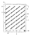
図1は、本発明の一実施形態であるスキャナ用読取シートの全体構成図である。 FIG. 1 is an overall configuration diagram of a scanner reading sheet according to an embodiment of the present invention.
本実施形態のスキャナ用読取シートは、図4に示すように、イメージスキャナ15の紙送り機構に挿入され、不定形な印刷紙片を確実にイメージファイリングするためのシートである。前記イメージスキャナ15は、USBケーブルを介してパーソナルコンピュータに接続されており、当該イメージスキャナ15で読み取った画像データがパーソナルコンピュータにインストールされたプログラムによってそのハードディスク装置内にイメージファイリング可能となっている。なお、図4では個人用のイメージスキャナを用いて説明しているが、同様に紙送り機構を備える複合機、あるいはフラットベッドスキャナでも読み取りは可能である。
As shown in FIG. 4, the scanner reading sheet according to the present embodiment is a sheet that is inserted into the paper feeding mechanism of the
台紙1は、被読取用紙を貼付するためのシート中央部2と読み取る情報を記載するためのシート底部3とで構成されている。シート中央部2の表面には、イメージスキャナ15
で画像ファイリングするための伝票11を貼付するために、粘着層10が設けられている。この粘着層10は、シート中央部2上に粘着剤を一定間隔で塗布して設けられている。
The
An
図において粘着層10はシート中央部2上において、斜め方向に所定間隔毎に配置された形状を有しているが、この粘着層10を構成する粘着剤には色素を加えて粘着剤自体が印刷用インク(以下、糊インクという)であるものを用いている。糊インクを用いることにより図3に示すように、汎用の印刷技術を用いて任意の文字、図形、記号等を粘着層10として設けることができ、これらを企業の商号、ロゴ、商品名等とすれば、伝票等が貼付されていない台紙部分ではこれらの印刷が目視できるため、スキャナ用読取シートそのものを広告媒体として使用することもでき、宣伝・広告効果も期待できる。また、糊インクは、印刷用インクであるため白黒のみならずカラー印字にも対応できるため、カラー広告として印刷されたものへシートのユーザの注目をより喚起させることができる。
In the figure, the pressure-sensitive
なお、台紙1には、伝票11を真っ直ぐ(台紙の側辺と並行)に貼付するために方眼目ラインのような罫線や所定間隔毎のマトリクス状に配置された十字記号等を糊インクで設けてもよい。
The
本実施形態においては、被読取用紙として伝票11を例に挙げているが、レシート、各種チケット、新聞・雑誌のスクラップ記事等、印刷面を有するイメージスキャナ15で読み取られるのに支障がない程度の厚さの紙片であれば読み取り可能である。
In the present embodiment, the
透明シート4は、前記台紙1を覆うように設けられており、当該透明シート4は、その表面に文字や図形を印刷可能な素材のポリプロピレン(PP)で構成され、その中央部を台紙1の表裏面方向に折り曲げることによって1枚の透明シートで台紙1の表裏面を覆う構造となっている。当該透明シート4は前記台紙1と台紙上部の透明シート固定部5で熱圧着または超音波圧着によって固定されている。透明シート4はこの透明シート固定部5以外の部分において、図1に示すように台紙1から剥離可能であり、透明シート4を剥離してからシート中央部2に伝票11を貼付し、再度透明シートで台紙1を覆うことで伝票11を挟持し固定できる。
The
なお、透明シート4は、ポリプロピレン(PP)に限定されるものではなく、その他の素材であってもよい。また、透明シート4は、無色透明に限定されるものではなく、イメージスキャナ15で読み取られるのに支障がない程度であれば半透明であってもよく、着色があってもよい。また、台紙1の素材も紙製に限定されるものではなくポリプロピレン(PP)、その他の素材であってもよい。
The
台紙1には、その一辺に綴じ穴7が設けられており、イメージスキャナ15での読み取り後に書類保存用のファイルに綴じることができるようになっている。この構成により、読み取った後にそのままファイルに保存が可能となる。この際、複数の台紙1を色分けをしてファイリングするようにしてもよい。なお、本実施形態では、綴じ穴7を台紙1の左側辺に設けた構成としているがこれに限定するものではなく、右側辺、あるいは上側、下側に設けた構成としてもよいし、綴じ穴7の個数・大きさもファイルのタイプに合わせた構成となる。
The
透明シート4は、透明シート固定部5より下の部分に、綴じ代8が開閉の際引っかからないよう一定間隔を空けた箇所に切り込み線6を入れて綴じ代8以外の透明シート4を剥離可能な構成とした。これによりファイルに綴じられた後でも透明シート4を開閉可能となる。シート中央部2とシート底部3との間で透明シート4にミシン目を入れた構成としてもよい。伝票11を貼付した台紙1をイメージスキャナ15で読み込んだ後、透明シート4のシート底部3の部分をミシン目により切り取るようにすることで、切り取りのある
シートはスキャナ読み込み済みであることを明示する目印になる。この構成により同じ伝票を二度読み込んでしまうことを防止できる。
The
台紙1には、イメージスキャナ15に読み取られる対象物が中央に来るように伝票11の貼付範囲を制限するための被読取用紙貼付枠9を設けて伝票11の貼付位置をガイドするようにしている。
The
本実施形態の図1においては、台紙1の表面のみの構成が示されているが、裏面も同様の構成となっており両面に伝票11が貼付可能である。その際、透明シート4は、1枚の透明シート4が透明シート固定部5の設けられている辺を中心に台紙1の表裏面方向に折り込まれて成形される構成とすることが好ましい。台紙1の表面・裏面2枚の透明シート4で台紙1を挟み込む構成も可能であるが、台紙1に対して1枚の透明シート4で表裏面をカバーさせるとともに、折り込んだ部分を透明シート固定部5で固定することによって、部材点数を低減できるとともに、イメージスキャナ15の自動紙送り機構に挿入した場合でも透明シート4と台紙1のずれが生じることをより確実に防止することができる。
In FIG. 1 of the present embodiment, the configuration of only the front surface of the
なお、本実施形態では、透明シート固定部5を台紙1の上側に設けた構成としているがこれに限定するものではなく、下側、あるいは左右側辺に設けた構成としてもよい。また、当該スキャナ用読取シートは、透明シート固定部5を設けない構成とすることも可能である。しかしながら、イメージスキャナ15の紙送り機構のローラの摩擦力により透明シート4と台紙1が分離してしまうことを防止することを目的とするには透明シート固定部5を設けた方が好ましい。
In the present embodiment, the transparent
図2は、本発明の一実施形態であるスキャナ用読取シートが読み取られる際の説明図である。図2のように伝票11を挟持した台紙1を図2中の矢印の方向(透明シート固定部5が設けられている辺側)からイメージスキャナ15の自動紙送り機構に挿入され読み取られる。
FIG. 2 is an explanatory diagram when a scanner reading sheet according to an embodiment of the present invention is read. As shown in FIG. 2, the
図2中の矢印と反対側、すなわちシート底部3側から読み取ることも可能であるが、矢印の方向から読み取られる方が好ましい。透明シート固定部5側からイメージスキャナ15の紙送り機構に挿入されることにより、粘着層10と透明シート4との間で伝票11が確実に固定されるとともに、紙送り機構のローラの摩擦力により透明シート4と台紙1が分離してしまうことを防止できるため、不定形な伝票11等の印刷紙片を確実にイメージファイリングすることができる。
Although it is possible to read from the opposite side of the arrow in FIG. 2, that is, from the
図3は、本発明の一実施形態であるスキャナ用読取シートのシート底部の説明図である。
シート底部3の右欄には、図1及び2に示すようにマーク12が付されており、会社名、商品名等の文字やロゴを配置して広告情報を表示することができる。また、図3に示すように、QRコード等の2次元バーコード13を付することにより、例えば台紙1が綴られる書類保存用のファイルの保管場所情報、読み込んだ日付等、台紙1に貼付されている伝票11等の被読取用紙に関するデータを格納させることができる。本実施形態では、2次元バーコードを例にあげているが、1次元バーコードであってもよい。
FIG. 3 is an explanatory diagram of a sheet bottom portion of a scanner reading sheet according to an embodiment of the present invention.
The
また、2次元バーコード13に企業データ(例えば、企業のサイトURL)を格納させたQRコードを用いれば、シートのユーザに携帯電話端末を用いて企業のサイトにアクセスさせることができ、上述の糊インクと併せてスキャナ用読取シートそのものを広告媒体として使用することができる。
Further, if a QR code in which company data (for example, company site URL) is stored in the two-
さらに、シート底部3には、□マークと文字から成るチェック欄14が設けられている
。例えば、チェック欄14には「交際費・通信費・旅費交通費・雑費」等の会計用の勘定科目が記載されており、伝票11が属する勘定科目に該当する□マークをペン等により黒く塗りつぶしておいて、イメージスキャナ15のOCR機能を使用すると、イメージファイリングの仕分けの際に上記勘定科目の該当箇所に仕分けすることができる。
Further, the
次に、本実施形態に係る粘着層10について言及する。台紙1に伝票11を貼付する際には、位置が曲がってしまう等により、何度か貼付し直すことが考えられる。その際、台紙1全体に粘着層10(糊インク)が設けられていると一度貼付した伝票11を剥がすことが困難となる。そこで、台紙1全体に糊インクを印刷(塗布)するのではなく、一定間隔を空けて印刷(塗布)するようにすることで、粘着強度を適切なものとした。糊インクの台紙面積に対する最適な比率及び粘着力については後述する。
Next, the
また、粘着層10を構成する糊インクには香料を混合してもよい。その場合、透明シート4を剥離した際に特定の匂いがするため、スキャナ用読取シートの利用促進を図れるとともに、当該匂いを比較的強い匂いで構成することによって、当該透明シート4を台紙1から剥離直後であれば匂いによって剥離した事実を検知することが可能となるため、伝票等の不正な差し替えの有無を調べることも可能である。
Further, a fragrance may be mixed in the glue ink constituting the
同様に会計上の不正防止を目的として、一度貼った伝票11を剥がすと粘着層10(糊インク)が伝票側に付着し、台紙側には粘着層10(糊インク)が残らない構成としてもよい。その場合、粘着層10が剥がれた台紙側には、予め粘着層10の下に印字しておいた文字(例えば「剥離禁止」等)が粘着層10が剥がれることによって表示される構成としてもよい。
Similarly, for the purpose of preventing fraud in accounting, the adhesive layer 10 (glue ink) adheres to the slip side when the
なお、台紙面積に対して、糊インクによる粘着層10が形成された面積の占める割合は2%以上で且つ100%以下であり、且つ糊インクの粘着力が0.001N/10mm以上で且つ10N/10mm以下であることが好ましいことが本発明者の実験により明らかとなった。
Note that the ratio of the area where the
本発明者の実験によれば、糊インクの印刷(塗布)による印刷面の占有面積が2%未満、且つ糊インクの粘着力が0.001N/10mm未満では粘着性が低すぎて伝票11を固定して挟持しにくいばかりかスキャナの自動紙送り機構に挿入した際に、台紙1と伝票11と透明シート4のずれを生じてしまう。また、印刷面の占有面積が100%、且つ糊インクの粘着力が10N/10mm以上となった場合、印刷面が見苦しくなるとともに粘着性が高くなりすぎて粘着層10からの伝票11の剥離が困難になってしまう。具体的には伝票11を剥離する際に捲りづらくなったり、破れてしまったりしてしまう。しかしながら、上記パラメータの範囲内であれば、スキャナ読み取り時の粘着性も適度に保たれ、且つ伝票11の剥離も好適に行うことができる。
According to the experiment of the present inventor, when the occupied area of the printing surface by the printing (application) of the glue ink is less than 2% and the adhesive strength of the glue ink is less than 0.001 N / 10 mm, the adhesiveness is too low and the
本実施形態では、図4に示すように、イメージスキャナ15の紙送り機構に挿入され、不定形な印刷紙片を確実にイメージファイリングするためのシートをモデルケースとしているため、スキャナ用読取シートの用紙サイズは、標準的なA4サイズを想定して示されている。しかしながら、イメージスキャナ15に読み取られるのに支障がないサイズであればA4サイズに限定されるものではない。
In this embodiment, as shown in FIG. 4, a sheet that is inserted into the paper feed mechanism of the
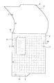
図5は、本発明の一実施形態である手帳用のスキャナ用読取シートである。これは、持ち運びように考えられたものであり図5に示すように、1箇所または複数箇所に折り目が設けられており、折り込まれて手帳に収納可能なものとした。図5では綴じ穴7が設けられておりシステム手帳に綴じられる構成となっている。通常の手帳の場合には挟んで持ち運ぶこととなる。
FIG. 5 is a scanner reading sheet for a notebook according to an embodiment of the present invention. This is considered to be carried, and as shown in FIG. 5, folds are provided at one place or a plurality of places and can be folded and stored in a notebook. In FIG. 5, a
図8は、スキャナ用読取シートの3つの実施形態を説明する断面図である。図8(a)は、図1に示したスキャナ用読取シートの断面図である。上述のとおり透明シート4は、1枚で台紙1の表裏を覆うように設けられており、台紙1には表面・裏面両面に粘着層10が設けられており伝票11が貼付されている。図8(a)に示すように、台紙1の表面で透明シート4と粘着層10に伝票11が挟持されており、裏面も同様である。
FIG. 8 is a cross-sectional view illustrating three embodiments of a scanner reading sheet. FIG. 8A is a cross-sectional view of the scanner reading sheet shown in FIG. As described above, the single
図8(b)は、図6に示した本発明の一実施形態であるスキャナ用読取シートの断面図である。図6に示したスキャナ用読取シートと図1に示したスキャナ用読取シートの最大の違いは、上述の透明シート4のみで成形されており台紙1を挟まない構成となっている点にある。1枚の透明シート4を中央部で強く折り込んで折り目16を設けて重ね合わせて、重ね合わせた内面の両面に粘着層10を設けて、伝票11を粘着層10に貼付して表裏面の透明シート4で挟持した構成である。図6の表裏面の透明シート4には、ファイリングされるための綴じ穴7が各々設けられている。また、シート下部3には約半分の部分から表裏面の透明シート4で左右対称的になるように切り取られている。これにより、透明シート4を剥離する際に剥がし易くなると共に、表裏面にチェック欄14を設けて文字情報を記入できる。
FIG. 8B is a cross-sectional view of the scanner reading sheet according to the embodiment of the present invention shown in FIG. The greatest difference between the scanner reading sheet shown in FIG. 6 and the scanner reading sheet shown in FIG. 1 is that it is formed of only the
図6のシートでは、透明シート4内面の両面に被読取用紙を貼付して読み取りを行う構成としてイメージスキャナ15の両面読み取りに対応可能としている。表裏面の透明シート4の粘着層は10ミリ単位の方眼目で構成されており、各々伝票11を貼付できる。この場合、重ね合わせた透明シート4の内面各々に粘着層10が重ならないように互い違いに設けられ、伝票11の印刷面側を各々の粘着層10に貼付して読み取りを行う。
In the sheet of FIG. 6, the
図8(c)は、図7に示した本発明の一実施形態であるスキャナ用読取シートの断面図である。1枚の透明シート4を中央部で強く折り込んで折り目16を設けて重ね合わせて、重ね合わせた内面の片面に粘着層10を設けて、伝票11を透明シート4と粘着層10とで挟持した構成である。図7に示したスキャナ用読取シートと図6に示したスキャナ用読取シートの最大の違いは、図6に示したスキャナ用読取シートは透明シート4の内面の両面に被読取用紙を貼付して読み取りを行う構成であるのに対し、図7に示したスキャナ用読取シートは透明シート4の内面の片面のみに被読取用紙を貼付して読み取りを行う構成となっている点にある。
FIG. 8C is a cross-sectional view of the scanner reading sheet according to the embodiment of the present invention shown in FIG. One
なお、図8(b)(c)では、スキャナ用読取シートを1枚の透明シート4で成形した構成としているがこれに限定されるものではなく、2枚の透明シート4を上述の図1に示したように透明シート固定部5で圧着した構成としてもよい。また、粘着層10を方眼目で設ける構成としているが、図1に示したように文字(企業の商号、ロゴ、商品名等)、図形、記号等を糊インクで設ける構成としてもよい。
In FIGS. 8B and 8C, the scanner reading sheet is formed by one
図8(b)(c)の構成によれば、粘着層10と透明シート4との間で伝票11が確実に固定されるとともに、透明シート4の折り目16側からイメージスキャナ15の紙送り機構に挿入されるため、紙送り機構のローラの摩擦力により透明シート4が剥離してしまうことなく、不定形な印刷紙片を確実にイメージファイリングすることができる。さらに、台紙1を不要とすることで部材点数を軽減できるとともに、図8の断面により示すように、(c)→(b)→(a)の順にシートの厚さを薄くできるので、読み取り時には厚みによる紙詰まりを防止して好適な紙送りが可能となり、保存時には厚みによる嵩張りを軽減できる。
8B and 8C, the
また、図8(a)(b)(c)に示した、伝票11を挟持した状態でのスキャナ用読取シートの厚みは0.001mm以上で且つ5.00mm以下の範囲とすることが好ましい
ことが本発明の実験により明らかとなった。
Further, it is preferable that the thickness of the scanner reading sheet shown in FIGS. 8A, 8B, and 8C is in the range of 0.001 mm or more and 5.00 mm or less in a state where the
本発明者の実験によれば、伝票11を挟持した状態でのスキャナ用読取シートの厚みを0.001mm未満とした場合、スキャナ用読取シートが薄すぎてスキャナの自動紙送り機構に挿入した際に、スキャナ内で紙詰まりを起こしてしまう。また、スキャナ用読取シートの厚みを5.00mm以上とした場合、スキャナ用読取シートの厚みによりスキャナの自動紙送り機構に挿入した際に紙送りが困難になってしまう。さらに、透明シート4の厚みによりスキャナ読み取り時の透過性が低下することで、読み取った画像データの画質も低下してしまう。しかしながら、スキャナ用読取シートの厚みが上記パラメータの範囲内であれば、スキャナ読み取り時の紙詰まりを防止し、好適なスキャナでの読み取りを行うことができる。
According to the experiment of the present inventor, when the thickness of the scanner reading sheet with the
本発明は、自動紙送り機構を備えたスキャナを用いたイメージファイリングに利用できる。 The present invention can be used for image filing using a scanner having an automatic paper feed mechanism.
1 台紙
2 シート中央部
3 シート底部
4 透明シート
5 透明シート固定部
6 切り込み線
7 綴じ穴
8 綴じ代
9 被読取用紙貼付枠
10 粘着層(糊インク)
11 伝票(被読取用紙)
12 マーク
13 2次元バーコード(QRコード)
14 チェック欄
15 イメージスキャナ
16 折り目
DESCRIPTION OF
11 slip (read paper)
12
14
Claims (9)
Priority Applications (1)
| Application Number | Priority Date | Filing Date | Title |
|---|---|---|---|
| JP2008132311A JP2009284091A (en) | 2008-05-20 | 2008-05-20 | Reading sheet for scanner |
Applications Claiming Priority (1)
| Application Number | Priority Date | Filing Date | Title |
|---|---|---|---|
| JP2008132311A JP2009284091A (en) | 2008-05-20 | 2008-05-20 | Reading sheet for scanner |
Publications (2)
| Publication Number | Publication Date |
|---|---|
| JP2009284091A true JP2009284091A (en) | 2009-12-03 |
| JP2009284091A5 JP2009284091A5 (en) | 2011-07-07 |
Family
ID=41454103
Family Applications (1)
| Application Number | Title | Priority Date | Filing Date |
|---|---|---|---|
| JP2008132311A Pending JP2009284091A (en) | 2008-05-20 | 2008-05-20 | Reading sheet for scanner |
Country Status (1)
| Country | Link |
|---|---|
| JP (1) | JP2009284091A (en) |
Cited By (3)
| Publication number | Priority date | Publication date | Assignee | Title |
|---|---|---|---|---|
| JP2010042533A (en) * | 2008-08-11 | 2010-02-25 | Topuri System Kk | Paste ink |
| JP2016071314A (en) * | 2014-09-29 | 2016-05-09 | 大塚 恭男 | Poster device |
| US9340044B2 (en) | 2014-02-14 | 2016-05-17 | Brother Kogyo Kabushiki Kaisha | Holding member, cutting apparatus and non-transitory computer-readable medium storing cutting operation control program |
Citations (2)
| Publication number | Priority date | Publication date | Assignee | Title |
|---|---|---|---|---|
| JPH0518164U (en) * | 1991-08-13 | 1993-03-05 | 村田機械株式会社 | Carrier Sheet for Facsimile |
| JPH0671884U (en) * | 1993-03-18 | 1994-10-07 | 有限会社樹脂印刷社 | Film for glass window |
-
2008
- 2008-05-20 JP JP2008132311A patent/JP2009284091A/en active Pending
Patent Citations (2)
| Publication number | Priority date | Publication date | Assignee | Title |
|---|---|---|---|---|
| JPH0518164U (en) * | 1991-08-13 | 1993-03-05 | 村田機械株式会社 | Carrier Sheet for Facsimile |
| JPH0671884U (en) * | 1993-03-18 | 1994-10-07 | 有限会社樹脂印刷社 | Film for glass window |
Cited By (3)
| Publication number | Priority date | Publication date | Assignee | Title |
|---|---|---|---|---|
| JP2010042533A (en) * | 2008-08-11 | 2010-02-25 | Topuri System Kk | Paste ink |
| US9340044B2 (en) | 2014-02-14 | 2016-05-17 | Brother Kogyo Kabushiki Kaisha | Holding member, cutting apparatus and non-transitory computer-readable medium storing cutting operation control program |
| JP2016071314A (en) * | 2014-09-29 | 2016-05-09 | 大塚 恭男 | Poster device |
Similar Documents
| Publication | Publication Date | Title |
|---|---|---|
| JP2931404B2 (en) | Printable co-area layer body and method of making same | |
| US5076490A (en) | Combination index card/post card | |
| GB2423958A (en) | Printable laminate | |
| US20030178837A1 (en) | Repositionably adherent note sheets which permit the passage of light, and assemblies thereof | |
| US8169654B2 (en) | Sequencing and reproducing sets of text and graphics across a collection of printable areas | |
| US6672624B2 (en) | Mailing form for non-impact printing | |
| JP2009284091A (en) | Reading sheet for scanner | |
| US9150007B2 (en) | Reusable printing carrier assembly and method of making and operating the assembly | |
| JP2006315252A (en) | Information recording booklet for sending | |
| JP5004122B2 (en) | Concealed postcard and application form with concealed postcard | |
| JP2003072262A (en) | Tag slip | |
| JP4890346B2 (en) | Application form with concealed postcard | |
| JP4401102B2 (en) | Delivery slip | |
| JP2006315255A (en) | Printing system of communication advertising booklet | |
| JP3065527U (en) | Signage for stores | |
| US20030197320A1 (en) | Method and system for minimizing the amount of paper utilized by a network printer | |
| KR200431340Y1 (en) | advertisement paper and information medium paper with advertisement paper | |
| US20070180746A1 (en) | Photograph label and album page | |
| NL1010364C1 (en) | Sheet of detachable business cards which can be overprinted, ten at a time, using computer printer | |
| JP3395851B2 (en) | Delivery slip | |
| US7910189B2 (en) | Photo sheet assembly with removable adhesive portions | |
| JP3072968U (en) | Notepad with advertising information | |
| JP3119328U (en) | Booklet type business card | |
| KR20160003106U (en) | Mouse pad of memo-note type | |
| GB2332877A (en) | Printed page with zig zag folded booklet attached thereto |
Legal Events
| Date | Code | Title | Description |
|---|---|---|---|
| A521 | Written amendment |
Free format text: JAPANESE INTERMEDIATE CODE: A523 Effective date: 20110520 |
|
| A621 | Written request for application examination |
Free format text: JAPANESE INTERMEDIATE CODE: A621 Effective date: 20110520 |
|
| A521 | Written amendment |
Free format text: JAPANESE INTERMEDIATE CODE: A523 Effective date: 20120511 |
|
| A977 | Report on retrieval |
Free format text: JAPANESE INTERMEDIATE CODE: A971007 Effective date: 20121130 |
|
| A131 | Notification of reasons for refusal |
Free format text: JAPANESE INTERMEDIATE CODE: A131 Effective date: 20121211 |
|
| A02 | Decision of refusal |
Free format text: JAPANESE INTERMEDIATE CODE: A02 Effective date: 20130409 |