JP2009283879A - Cable with sealing member - Google Patents
Cable with sealing member Download PDFInfo
- Publication number
- JP2009283879A JP2009283879A JP2008137340A JP2008137340A JP2009283879A JP 2009283879 A JP2009283879 A JP 2009283879A JP 2008137340 A JP2008137340 A JP 2008137340A JP 2008137340 A JP2008137340 A JP 2008137340A JP 2009283879 A JP2009283879 A JP 2009283879A
- Authority
- JP
- Japan
- Prior art keywords
- sealing member
- cable
- inner peripheral
- main body
- hole
- Prior art date
- Legal status (The legal status is an assumption and is not a legal conclusion. Google has not performed a legal analysis and makes no representation as to the accuracy of the status listed.)
- Granted
Links
Images


Classifications
-
- Y—GENERAL TAGGING OF NEW TECHNOLOGICAL DEVELOPMENTS; GENERAL TAGGING OF CROSS-SECTIONAL TECHNOLOGIES SPANNING OVER SEVERAL SECTIONS OF THE IPC; TECHNICAL SUBJECTS COVERED BY FORMER USPC CROSS-REFERENCE ART COLLECTIONS [XRACs] AND DIGESTS
- Y02—TECHNOLOGIES OR APPLICATIONS FOR MITIGATION OR ADAPTATION AGAINST CLIMATE CHANGE
- Y02A—TECHNOLOGIES FOR ADAPTATION TO CLIMATE CHANGE
- Y02A30/00—Adapting or protecting infrastructure or their operation
- Y02A30/14—Extreme weather resilient electric power supply systems, e.g. strengthening power lines or underground power cables
Abstract
Description
本発明は、電子機器の筐体に形成されたケーブル通し孔と該ケーブル通し孔に通されるケーブルとの間を封止する封止部材を備えた封止部材付ケーブルに関する。 The present invention relates to a cable with a sealing member provided with a sealing member that seals between a cable through hole formed in a housing of an electronic device and a cable passed through the cable through hole.
近年、携帯用電話機(電子機器)は、更なる小型化を図るため、折り畳み式等の種々の形態のものが提供されている。折り畳み式の携帯用電話機は、操作ボタン等と液晶ディスプレイ等が2つの筐体にそれぞれ配設され、2つの筐体がヒンジ機構を介して旋回自在に接続された構造となっている。そして、ユーザは、携帯用電話機を使用しないときは、2つの筐体をヒンジ機構を中心に折り畳んで携帯し、携帯用電話機を使用するときは、2つの筐体をヒンジ機構を中心に展開して操作ボタンを押したり液晶ディスプレイを見て通話やメール送受信等を行う。 In recent years, portable telephones (electronic devices) have been provided in various forms such as a folding type in order to further reduce the size. A foldable portable telephone has a structure in which an operation button and a liquid crystal display are disposed in two casings, and the two casings are connected to each other through a hinge mechanism so as to be rotatable. When the user does not use the portable phone, the user folds the two cases around the hinge mechanism and carries the case. When using the portable phone, the user unfolds the two cases around the hinge mechanism. Then press the operation button or look at the LCD to make calls or send / receive emails.
この方式の携帯用電話機は、操作ボタン等が配設された筐体と液晶ディスプレイ等が配設された筐体を備えているため、両筐体に内蔵されている回路間を電気的に接続する配線が必要となる。このため、例えば特許文献1には、各筐体のヒンジ機構側の側面に筐体内外に通じるヒンジに平行な長尺な通し孔(ケーブル通し孔)を形成し、各通し孔にフレキシブル配線基板(ケーブル)を通して両筐体に内蔵されている回路間を電気的に接続し、各通し孔をフレキシブル配線基板に一体化されている防水用部材(封止部材)により密閉(封止)したものが開示されている。
上述した従来のフレキシブル配線基板では、防水用部材をインサート成形により一体化している。このため、インサート成形用金型内でのフレキシブル配線基板の位置決めを誤った場合、フレキシブル配線基板の一部が、一体化された防水用部材の側面から露出してしまうことがあり、かかる防水用部材では筐体の通し孔を密閉できず筐体内に水分が浸入したときは内蔵回路を短絡させるおそれがある。このような問題を解消するためには、インサート成形用金型内でのフレキシブル配線基板の位置決めを高精度に行う必要があって金型内へのフレキシブル配線基板の設置に手間が掛かるなど工数が増加し、結果的に製造コスト増、生産性の低下を招いていた。 In the conventional flexible wiring board described above, the waterproof member is integrated by insert molding. For this reason, if positioning of the flexible wiring board in the mold for insert molding is mistaken, a part of the flexible wiring board may be exposed from the side surface of the integrated waterproofing member. The member cannot seal the through-hole of the housing, and there is a risk of short-circuiting the built-in circuit when moisture enters the housing. In order to solve such problems, it is necessary to position the flexible wiring board in the insert molding die with high accuracy, and it takes time to install the flexible wiring board in the die. As a result, the manufacturing cost increased and the productivity decreased.
また、このようなフレキシブル配線基板は、凹凸のない平面形状をしており、防水用部材を一体成形しやすいが、このフレキシブル配線基板を用いた場合には、高速、大容量のデータ伝送の送受信時にノイズの影響を受けることがあり、このようなノイズの影響を除去するためには、シールドされた複数本の同軸ケーブルからなるフラットケーブルを用いることが好ましい。しかし、この種のフラットケーブルは、極細径の同軸ケーブルが用いられており、これをフラット化したフラットケーブルは、その外周部に凹凸形状を有しており、密閉のための防水用部材を一体化するのが困難である。 In addition, such a flexible wiring board has a flat shape without irregularities, and it is easy to integrally form a waterproof member. However, when this flexible wiring board is used, transmission and reception of high-speed, large-capacity data transmission is possible. It is sometimes affected by noise, and in order to remove the influence of such noise, it is preferable to use a flat cable composed of a plurality of shielded coaxial cables. However, this type of flat cable uses an ultra-thin coaxial cable, and the flat cable that has been flattened has an irregular shape on its outer periphery, and is integrated with a waterproofing member for sealing. It is difficult to convert.
さらに、このような極細径の同軸ケーブルを携帯電話機などの配線に使用した場合には、フレキシブル配線基板と同様に金型内での同軸ケーブルの位置決め・保持が必要となるが、保持圧力及び溶融樹脂の流動圧力に対して同軸ケーブル自体が座屈したり、同軸ケーブルが断線する恐れなどがあり、接着剤により防水用部材と気密的に一体化する方法がとられることとなる。したがって、この方法も前記したフレキシブル配線基板と同様に多くの手間を要することとなり、製造コストの増加、生産性の低下を招いていた。 Furthermore, when such an ultra-thin coaxial cable is used for wiring of a mobile phone or the like, it is necessary to position and hold the coaxial cable in the mold as with the flexible wiring board. The coaxial cable itself may buckle against the flow pressure of the resin, or the coaxial cable may be disconnected, and a method of hermetically integrating with the waterproofing member with an adhesive is taken. Therefore, this method also requires a lot of labor similar to the above-described flexible wiring board, resulting in an increase in manufacturing cost and a decrease in productivity.
本発明は、上記のような課題に鑑みなされたものであり、その目的は、筐体に形成されたケーブル通し孔と該ケーブル通し孔に通されるケーブルとの間を確実に封止することができる封止部材を備えた封止部材付ケーブルを良好な生産性をもって提供することにある。 The present invention has been made in view of the above-described problems, and an object of the present invention is to reliably seal between a cable through hole formed in a housing and a cable passed through the cable through hole. It is providing the cable with a sealing member provided with the sealing member which can be performed with favorable productivity.
上記目的達成のため、本発明の封止部材付ケーブルでは、電子機器の筐体に形成されたケーブル通し孔と該ケーブル通し孔に通されるケーブルとの間を封止する封止部材を備えた封止部材付ケーブルであって、前記封止部材は、前記ケーブル通し孔の内周部と密着する本体外周部及び前記ケーブルが挿通される本体内周部を有する封止部材本体と、該封止部材本体から突設され前記本体内周部と連通して前記ケーブルが挿通される突出内周部を有する封止部材突出部とを備え、前記ケーブルは、前記封止部材突出部の突出内周部に融着されていることを特徴としている。 In order to achieve the above object, the cable with a sealing member of the present invention includes a sealing member that seals between a cable through hole formed in the housing of the electronic device and a cable passed through the cable through hole. A sealing member main body having a main body outer peripheral portion in close contact with an inner peripheral portion of the cable through hole and a main body inner peripheral portion through which the cable is inserted; A sealing member projecting portion that protrudes from the sealing member main body and has a projecting inner peripheral portion that communicates with the inner peripheral portion of the main body and is inserted into the cable, and the cable projects from the sealing member projecting portion. It is characterized by being fused to the inner periphery.
これにより、予め成形されている封止部材の封止部材突出部に形成されている突出内周部にケーブルを挿通してから突出内周部とケーブル外皮を融着するので、封止部材本体に融着時の熱による変形などの影響を抑えることが可能となり、封止部材本体は高精度な形状を維持することが可能となる。この結果、従来のようにケーブルの一部が封止部材の側面から露出してしまうことはなく、筐体に形成されたケーブル通し孔と該ケーブル通し孔に通されるケーブルとの間を確実に封止して筐体内への水分の浸入を防止し内蔵回路を保護することができる。 As a result, the cable is inserted into the protruding inner peripheral portion formed on the sealing member protruding portion of the sealing member that is molded in advance, and then the protruding inner peripheral portion and the cable outer shell are fused, so that the sealing member main body In addition, it is possible to suppress the influence of deformation due to heat at the time of fusion, and the sealing member body can maintain a highly accurate shape. As a result, a part of the cable is not exposed from the side surface of the sealing member as in the conventional case, and the cable passing through the cable passing hole formed in the housing and the cable passing through the cable passing hole are surely secured. The internal circuit can be protected by preventing the ingress of moisture into the housing.
また、前記封止部材突出部は、側壁がR形状を有することを特徴としている。また、前記封止部材突出部は、側壁に切欠き部を有することを特徴としている。これにより、封止部材突出部側面を更に撓み易くすることができるので、封止部材突出部の突出内周部の半溶融した上下内面をケーブルの外皮の上下面に容易かつ確実に融着することができ、ケーブルと封止部材との気密性を一層向上させることができる。また、少なくとも前記封止部材本体の本体外周部は、前記ケーブル通し孔の内周部よりも軟質の樹脂で形成されていることを特徴としている。これにより、封止部材本体の本体外周部は変形してケーブル通し孔の内周部に密着することができるので、封止部材本体の本体外周部とケーブル通し孔の内周部との間を確実に封止することができる。また、少なくとも前記封止部材突出部は、前記ケーブルの外皮と組成が近似する樹脂で形成されていることを特徴としている。これにより、封止部材突出部とケーブルの外皮との融着度合いを高めることができるので、封止部材突出部とケーブルの外皮との間を確実に封止することができる。そして、封止部材本体の本体外周部と筐体のケーブル通し孔の内周部との間、及び封止部材突出部とケーブルの外皮との間を確実に封止するという特徴を合わせることにより、筐体内への水分の浸入を防止し内蔵回路を保護することができる。 Further, the sealing member protrusion has a side wall having an R shape. Further, the sealing member protrusion has a notch on the side wall. As a result, the side surface of the protruding portion of the sealing member can be more easily bent, so that the semi-molten upper and lower inner surfaces of the protruding inner peripheral portion of the protruding portion of the sealing member can be easily and reliably fused to the upper and lower surfaces of the outer cover of the cable. The airtightness between the cable and the sealing member can be further improved. Further, at least the outer peripheral portion of the main body of the sealing member main body is formed of a softer resin than the inner peripheral portion of the cable through hole. As a result, the outer peripheral part of the main body of the sealing member main body can be deformed and can be brought into close contact with the inner peripheral part of the cable through hole. It can be surely sealed. Further, at least the sealing member protrusion is formed of a resin having a composition similar to that of the outer sheath of the cable. Accordingly, the degree of fusion between the sealing member protrusion and the cable outer sheath can be increased, so that the gap between the sealing member protrusion and the cable outer sheath can be reliably sealed. And by combining the characteristics of reliably sealing between the outer peripheral part of the main body of the sealing member main body and the inner peripheral part of the cable through hole of the housing and between the sealing member protruding part and the outer sheath of the cable This prevents moisture from entering the housing and protects the built-in circuit.
以下、本発明の実施形態について説明する。尚、以下に説明する実施形態は特許請求の範囲にかかる発明を限定するものではなく、また実施形態の中で説明されている特徴の組み合わせの全てが発明の解決手段に必須であるとは限らない。 Hereinafter, embodiments of the present invention will be described. The embodiments described below do not limit the invention according to the scope of claims, and all combinations of features described in the embodiments are not necessarily essential to the solution means of the invention. Absent.
図1(A)は、本発明の第1の実施形態に係る封止部材付ケーブルに用いられる封止部材を示す斜視図、同図(B)は、その封止部材付ケーブルを示す斜視図である。図2は、電子機器の筐体の分解斜視図及び封止部材付ケーブルを電子機器の筐体に取り付けた状態を示す断面図である。図3は、封止部材をフラットケーブルに融着する製造方法を示す図である。図1(B)に示すように、封止部材付ケーブル1は、封止部材10をフラットケーブル20に一体化した構成となっている。
FIG. 1A is a perspective view showing a sealing member used for a cable with a sealing member according to the first embodiment of the present invention, and FIG. 1B is a perspective view showing the cable with a sealing member. It is. FIG. 2 is an exploded perspective view of the housing of the electronic device and a cross-sectional view illustrating a state where the cable with the sealing member is attached to the housing of the electronic device. FIG. 3 is a view showing a manufacturing method for fusing the sealing member to the flat cable. As shown in FIG. 1B, the
図1(A)に示すように、封止部材10は、封止部材本体11とこの封止部材本体11に一体化された封止部材突出部12を備えている。封止部材本体11は、長円環状の断面を有する筒状体に形成されており、外周の軸方向略中央には全周にわたってシール部材13(図1(B)参照)が嵌め込まれる半円形状の断面を有する溝11aが形成されている。封止部材突出部12は、封止部材本体11の外径(長径及び短径)より小径の外径(長径及び短径)であって封止部材本体11の内径(長径及び短径)と同径の内径(長径及び短径)の長円環状の断面を有する筒状体に形成されている。この封止部材突出部12の筒状体は、後に述べる融着時の加熱により、封止部材本体11は変形しないが、容易に溶融しやすいように封止部材本体11より肉厚が薄手に形成されている。そして、封止部材突出部12は、その突出内周部12bと封止部材本体11の本体内周部11bとが連通するように封止部材本体11の一端面から突出して形成されている。
As shown in FIG. 1A, the sealing
図1(B)に示すように、フラットケーブル20は、複数本(この例では3本)の同軸ケーブル21を並列配置して一体化した構成となっている。この同軸ケーブル21は、1本の導体もしくは複数本の導体を撚り合わせて作られた中心導体22の周囲に絶縁材料から成る誘電体層23を形成し、この誘電体層23の外周に外部導体24を形成し、この外部導体24の外周に外被25が形成された構成となっている。
As shown in FIG. 1B, the
封止部材本体11の本体内周部11b及び封止部材突出部12の突出内周部12bは、長径及び短径がフラットケーブル20の幅及び厚さより若干大きくなるように形成されている。本体内周部11b及び突出内周部12bにフラットケーブル20が挿通され、突出内周部12bにて外被25が融着されて一体化されている。これにより、封止部材10とフラットケーブル20との間のシール性を保っている。
The main body inner
封止部材本体11の溝11aには、Oリング等のシール部材13(封止部材本体11の本体外周部)が嵌め込まれる。シール部材13が嵌め込まれた封止部材本体11は、図2に示すように、電子機器の筐体30を構成する下蓋32に設けられたケーブル通し孔33に嵌め込まれる。このケーブル通し孔33は、封止部材本体11に嵌め込まれたシール部材13の外形よりも若干小さく形成されているので、シール部材13は、ケーブル通し孔33の内周部33aにより押圧される。ここで、シール部材13は、下蓋32(ケーブル通し孔33の内周部33a)よりも軟質の樹脂で形成されている。このため、ケーブル通し孔33の内周部33aによる圧縮力によりシール部材13が若干潰れてその外周がケーブル通し孔33の内周部33aに密着する。これにより、封止部材10と筐体30のケーブル通し孔33との間のシール性を保っている。尚、封止部材10は、上蓋31側の外側開口縁部31aが突出形成されることにより筐体30外への抜けが防止され、また、下蓋32側の内側開口縁部32aが突出形成されることにより筐体30内への入り込みが防止されている。また、電子機器の筐体30を構成する上蓋31と下蓋32は、下蓋32の上蓋31との接合面に形成された溝32b内に嵌め込まれたシール部材32cを介して接合される。これにより、筐体30の上蓋31と下蓋32との間のシール性を保っている。
A sealing
尚、溝11aの代わりに半円形状の断面を有する凸部(封止部材本体11の本体外周部)をシール部材として封止部材本体11の外周の軸方向略中央に全周にわたって一体成形しても良い。これにより、部品点数を減じることができる。このときの凸部を含む封止部材本体11は、上蓋31及び下蓋32(ケーブル通し孔33の内周部33a)よりも軟質の樹脂で形成されており、上蓋31及び下蓋32による圧縮力により凸部が若干潰れてその外周がケーブル通し孔33の内周部33aに密着する。これによっても、封止部材10と筐体30のケーブル通し孔33との間のシール性を保つことができる。また、封止部材突出部12に筐体30からの抜け止めとなるつば部を一体成形しても良い。
In addition, the convex part (main body outer peripheral part of the sealing member main body 11) which has a semicircular cross section instead of the
以上のような構成の封止部材付ケーブル1の製造方法について説明する。先ず、封止部材10を例えば射出成形等により製作し、フラットケーブル20を例えば押出成形等により製作する。封止部材10の材料としては、例えばフッ素樹脂の一種である接着性を有する変性ETFE(エチレン−テトラフルオロエチレン共重合体)(商品名:ネオフロンEFEP,RP−4020、ダイキン社製)(融点:155°C〜170°C)を用いる。フラットケーブル20の中心導体22の材料としては、例えば銀メッキ軟銅線を用いる。誘電体層23の材料としては、例えばテトラフルオロエチレン−パーフルオロアルキルビニルエーテル共重合体(PFA)(融点:300°C)を用いる。外被25の材料としては、例えばエチレンーテトラフルオロエチレン共重合体(ETFE)(融点:260°C)を用いる。
A method for manufacturing the
次に、図3に示すように、製作した封止部材10の溝11aにOリング等のシール部材13を嵌め込む。一方、製作したフラットケーブル20の一端側の外皮25、外部導体24及び誘電体層23を取り除き、中心導体22の一端にコネクタ2を半田付けする。そして、フラットケーブル20を他端側から封止部材10の突出内周部12bに挿通し、更に本体内周部11bに挿通して外部に引き出す。
Next, as shown in FIG. 3, a
封止部材10をコネクタ2から所定距離離れたフラットケーブル20の所定位置に位置決めしたら、封止部材10の封止部材突出部12のみが加熱されるようにインパルスヒータ等の加熱装置40にセットする。即ち、加熱装置40の台座41の上に離型材となる例えばポリイミドフィルム42を載置し、該フィルム42の上に封止部材10の封止部材突出部12のみを載置し、更に該封止部材突出部12の上に離型材となるポリイミドフィルム43を載置する。そして、加熱部44を該フィルム43の上から押し当てて封止部材突出部12を融点以上となるように加熱する。
When the sealing
ここで、加熱部44の押し当て方向と直交する方向の封止部材突出部12の側面形状は図1(B)に示すように半円形状(R形状)となっているため、加熱部44の押し当て力により該側面12aは撓み易くなっている。このため、先ず封止部材突出部12の突出内周部12bの半溶融した上下内面がフラットケーブル20の外皮25の上下面に融着し、次に封止部材突出部12を構成する溶融した樹脂がフラットケーブル20の側面や隙間に流れ込んで外皮25に融着する。このとき、上述したように封止部材突出部12の材料は変性ETFEを選択し、外皮25の材料は変性ETFEの組成に近似したETFEを選択しているため、封止部材突出部12と外皮25との融着度合いを高めることができ、封止部材突出部12と外皮25との間を確実に封止することができる。
Here, the side surface shape of the sealing
尚、図4の封止部材10の変形例に示すように、封止部材突出部12の両側側面12aに軸方向に延びるスリット12cを1本もしくは複数本入れておくことにより、該側面12aを更に撓み易くすることができ、封止部材突出部12の突出内周部12bの半溶融した上下内面をフラットケーブル20の外皮25の上下面に容易かつ確実に融着することができ、フラットケーブル20と封止部材10との気密性を一層向上させることができる。また、加熱装置40の例えば台座41に加振部を予め組み込んでおき、加熱部44により封止部材突出部12を加熱する際に加振部により封止部材突出部12を加振することで、封止部材突出部12を構成する溶融樹脂をフラットケーブル20の周囲に容易かつ確実に流れ込ませることができ、フラットケーブル20と封止部材10との気密性を一層向上させることができる。
In addition, as shown in the modification of the sealing
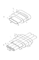
図5は、本発明の第2の実施形態に係る封止部材付ケーブルを図1(B)に対応させて示す斜視図であり、同一構成部材は同一番号を付して詳細な説明は省略する。この封止部材付ケーブル2は、図1(B)に示す封止部材付ケーブル1を上下に2段重ねて一体化したような構成となっている。封止部材50は、封止部材本体51とこの封止部材本体51に一体化された封止部材突出部52を備えている。封止部材本体51の外周の軸方向略中央には全周にわたってシール部材53が嵌め込まれる半円形状の断面を有する溝51aが形成されている。封止部材突出部52は、その突出内周部52bと封止部材本体51の本体内周部51bとが連通するように封止部材本体51の一端面から突出して形成されている。
FIG. 5 is a perspective view showing a cable with a sealing member according to the second embodiment of the present invention corresponding to FIG. 1B, and the same components are denoted by the same reference numerals and detailed description thereof is omitted. To do. The cable 2 with a sealing member has a configuration in which the
このように2段(複数段)構成の突出内周部52bを形成することにより、同軸ケーブル21の並列本数を減じたフラットケーブル20に分けて挿通することができるので、封止部材50の幅をフラットケーブル20の幅に合わせて小さくすることができ、特に筐体30内の部品レイアウトによりケーブル通し孔33の幅が制限されるときに有効となる。
In this way, by forming the protruding inner
尚、上述した実施形態では、複数本の同軸ケーブルを一列に並べたフラットケーブルについて説明したが、同軸ケーブル以外の複数本のケーブルを一列に並べたフラットケーブルや複数本の同軸ケーブル等を円形状に束ねたケーブルであっても同様に適用可能である。また、封止部材突出部12を封止部材本体11の一端面側のみに形成したが、両端面側にそれぞれ形成しても良い。また、外被25の材料としてETFEを用いたが、PFAであっても多少融着性は低下するが用いることができる。
In the above-described embodiment, the flat cable in which a plurality of coaxial cables are arranged in a row has been described. However, a flat cable in which a plurality of cables other than the coaxial cable are arranged in a row, a plurality of coaxial cables, and the like are circular. Even a cable bundled together can be similarly applied. Moreover, although the sealing
本発明に係る封止部材付ケーブルは、例えば携帯用電話機、パーソナルコンピュータ等の電子機器全般に適用が可能である。 The cable with a sealing member according to the present invention can be applied to all electronic devices such as mobile phones and personal computers.
1、2 封止部材付ケーブル、 10,50 封止部材、 11,51 封止部材本体、
11a、51a 溝、 11b、51b 本体内周部、 12,52 封止部材突出部、
12a 封止部材突出部側面、 12b、52b 突出内周部、 12c スリット、
13、53 シール部材(本体外周部)、 20 フラットケーブル、
21 同軸ケーブル、 22 中心導体、 23 誘電体層、 24 外部導体、
25 外皮、 30 筐体、 33 ケーブル通し孔、
33a ケーブル通し孔内周部、 40 加熱装置
1, 2, cable with sealing member, 10, 50 sealing member, 11, 51 sealing member body,
11a, 51a groove, 11b, 51b body periphery, 12, 52 sealing member protrusion,
12a Sealing member protruding portion side surface, 12b, 52b protruding inner peripheral portion, 12c slit,
13, 53 Seal member (outer peripheral part of main body), 20 flat cable,
21 coaxial cable, 22 central conductor, 23 dielectric layer, 24 outer conductor,
25 outer skin, 30 housing, 33 cable hole,
33a Cable through hole inner periphery, 40 heating device
Claims (5)
前記封止部材は、前記ケーブル通し孔の内周部と密着する本体外周部及び前記ケーブルが挿通される本体内周部を有する封止部材本体と、該封止部材本体から突設され前記本体内周部と連通して前記ケーブルが挿通される突出内周部を有する封止部材突出部とを備え、
前記ケーブルは、前記封止部材突出部の突出内周部に融着されていることを特徴とする封止部材付ケーブル。 A cable with a sealing member provided with a sealing member for sealing between a cable through hole formed in a housing of an electronic device and a cable passed through the cable through hole,
The sealing member includes a main body outer peripheral portion that is in close contact with an inner peripheral portion of the cable through hole, and a main body inner peripheral portion through which the cable is inserted, and a main body that protrudes from the sealing member main body. A sealing member protruding portion having a protruding inner peripheral portion that communicates with the inner peripheral portion and through which the cable is inserted;
The cable with a sealing member, wherein the cable is fused to a protruding inner peripheral portion of the protruding portion of the sealing member.
Priority Applications (1)
| Application Number | Priority Date | Filing Date | Title |
|---|---|---|---|
| JP2008137340A JP5015064B2 (en) | 2008-05-26 | 2008-05-26 | Cable with sealing member |
Applications Claiming Priority (1)
| Application Number | Priority Date | Filing Date | Title |
|---|---|---|---|
| JP2008137340A JP5015064B2 (en) | 2008-05-26 | 2008-05-26 | Cable with sealing member |
Publications (2)
| Publication Number | Publication Date |
|---|---|
| JP2009283879A true JP2009283879A (en) | 2009-12-03 |
| JP5015064B2 JP5015064B2 (en) | 2012-08-29 |
Family
ID=41453979
Family Applications (1)
| Application Number | Title | Priority Date | Filing Date |
|---|---|---|---|
| JP2008137340A Expired - Fee Related JP5015064B2 (en) | 2008-05-26 | 2008-05-26 | Cable with sealing member |
Country Status (1)
| Country | Link |
|---|---|
| JP (1) | JP5015064B2 (en) |
Cited By (7)
| Publication number | Priority date | Publication date | Assignee | Title |
|---|---|---|---|---|
| JP2011228892A (en) * | 2010-04-19 | 2011-11-10 | Panasonic Corp | Foldable electronic apparatus |
| JP2011228169A (en) * | 2010-04-21 | 2011-11-10 | Sumitomo Electric Ind Ltd | Small-diameter coaxial cable harness and method of manufacturing the same |
| WO2012105075A1 (en) * | 2011-02-03 | 2012-08-09 | 住友電気工業株式会社 | Narrow diameter coaxial cable harness and method of manufacturing same |
| JP2013026181A (en) * | 2011-07-26 | 2013-02-04 | Sumitomo Electric Ind Ltd | Small-diameter cable harness |
| CN104123983A (en) * | 2014-08-07 | 2014-10-29 | 徐可澍 | Flat cable |
| JP2015225802A (en) * | 2014-05-29 | 2015-12-14 | 株式会社フジクラ | Terminal-provided wire and production method thereof |
| CN109155168A (en) * | 2016-05-13 | 2019-01-04 | 株式会社自动网络技术研究所 | Flat cable and sealing cable |
Citations (5)
| Publication number | Priority date | Publication date | Assignee | Title |
|---|---|---|---|---|
| JPS5152996U (en) * | 1974-10-21 | 1976-04-22 | ||
| JPS61151272U (en) * | 1985-03-11 | 1986-09-18 | ||
| JPS61205185U (en) * | 1985-06-14 | 1986-12-24 | ||
| JPH09320370A (en) * | 1996-05-28 | 1997-12-12 | Sumitomo Wiring Syst Ltd | Grommet |
| JP2006344813A (en) * | 2005-06-09 | 2006-12-21 | Casio Hitachi Mobile Communications Co Ltd | Flexible wiring board |
-
2008
- 2008-05-26 JP JP2008137340A patent/JP5015064B2/en not_active Expired - Fee Related
Patent Citations (5)
| Publication number | Priority date | Publication date | Assignee | Title |
|---|---|---|---|---|
| JPS5152996U (en) * | 1974-10-21 | 1976-04-22 | ||
| JPS61151272U (en) * | 1985-03-11 | 1986-09-18 | ||
| JPS61205185U (en) * | 1985-06-14 | 1986-12-24 | ||
| JPH09320370A (en) * | 1996-05-28 | 1997-12-12 | Sumitomo Wiring Syst Ltd | Grommet |
| JP2006344813A (en) * | 2005-06-09 | 2006-12-21 | Casio Hitachi Mobile Communications Co Ltd | Flexible wiring board |
Cited By (8)
| Publication number | Priority date | Publication date | Assignee | Title |
|---|---|---|---|---|
| JP2011228892A (en) * | 2010-04-19 | 2011-11-10 | Panasonic Corp | Foldable electronic apparatus |
| JP2011228169A (en) * | 2010-04-21 | 2011-11-10 | Sumitomo Electric Ind Ltd | Small-diameter coaxial cable harness and method of manufacturing the same |
| WO2012105075A1 (en) * | 2011-02-03 | 2012-08-09 | 住友電気工業株式会社 | Narrow diameter coaxial cable harness and method of manufacturing same |
| JP2013026181A (en) * | 2011-07-26 | 2013-02-04 | Sumitomo Electric Ind Ltd | Small-diameter cable harness |
| JP2015225802A (en) * | 2014-05-29 | 2015-12-14 | 株式会社フジクラ | Terminal-provided wire and production method thereof |
| CN104123983A (en) * | 2014-08-07 | 2014-10-29 | 徐可澍 | Flat cable |
| CN109155168A (en) * | 2016-05-13 | 2019-01-04 | 株式会社自动网络技术研究所 | Flat cable and sealing cable |
| CN109155168B (en) * | 2016-05-13 | 2020-04-10 | 株式会社自动网络技术研究所 | Flat cable and water-stop cable |
Also Published As
| Publication number | Publication date |
|---|---|
| JP5015064B2 (en) | 2012-08-29 |
Similar Documents
| Publication | Publication Date | Title |
|---|---|---|
| JP5015064B2 (en) | Cable with sealing member | |
| US8546697B2 (en) | Bundled flexible circuit board based flat cable with water resistant section | |
| JP5134711B2 (en) | Bundling flexible wiring with waterproof structure | |
| TWI614643B (en) | Accessory for a handset, accessory button controllers, and method of manufacturing accessory button controllers | |
| WO2010087141A1 (en) | Electronic device | |
| JP4508213B2 (en) | Portable electronic devices | |
| JP6050164B2 (en) | Portable device | |
| JP5296462B2 (en) | Cable and cable with sealing member | |
| JP5568136B2 (en) | Manufacturing method of cable assembly | |
| JP2010263298A (en) | Waterproof type portable terminal | |
| JP5394456B2 (en) | Cable assembly and method for manufacturing cable assembly | |
| US20190074646A1 (en) | Mobile terminal and method for manufacturing earphone socket | |
| JP2008301440A (en) | Electronic equipment and method for storing substrate in electronic equipment | |
| JP3989453B2 (en) | Intermediate unit and manufacturing method thereof | |
| JP2010283443A (en) | Solid-state imaging apparatus, and method of manufacturing the same | |
| JP3989454B2 (en) | Intermediate unit | |
| JP2014216826A (en) | Connection structure having sealability | |
| JP2011258726A (en) | Sealing member and cable with sealing member | |
| JP5325538B2 (en) | Portable electronic devices | |
| CN107659685B (en) | Waterproof assembly and mobile terminal | |
| JP5503329B2 (en) | Electronics | |
| JP5447572B2 (en) | Wiring body arrangement structure and mobile phone | |
| JP2009177570A (en) | Mobile terminal device | |
| JP2012256566A (en) | Small-diameter cable harness | |
| JP2010016123A (en) | Arrangement structure of wiring body, mobile phone, and wiring component |
Legal Events
| Date | Code | Title | Description |
|---|---|---|---|
| A621 | Written request for application examination |
Free format text: JAPANESE INTERMEDIATE CODE: A621 Effective date: 20110405 |
|
| A977 | Report on retrieval |
Free format text: JAPANESE INTERMEDIATE CODE: A971007 Effective date: 20120124 |
|
| A131 | Notification of reasons for refusal |
Free format text: JAPANESE INTERMEDIATE CODE: A131 Effective date: 20120131 |
|
| A521 | Written amendment |
Free format text: JAPANESE INTERMEDIATE CODE: A523 Effective date: 20120329 |
|
| TRDD | Decision of grant or rejection written | ||
| A01 | Written decision to grant a patent or to grant a registration (utility model) |
Free format text: JAPANESE INTERMEDIATE CODE: A01 Effective date: 20120530 |
|
| A01 | Written decision to grant a patent or to grant a registration (utility model) |
Free format text: JAPANESE INTERMEDIATE CODE: A01 |
|
| A61 | First payment of annual fees (during grant procedure) |
Free format text: JAPANESE INTERMEDIATE CODE: A61 Effective date: 20120606 |
|
| FPAY | Renewal fee payment (event date is renewal date of database) |
Free format text: PAYMENT UNTIL: 20150615 Year of fee payment: 3 |
|
| R150 | Certificate of patent or registration of utility model |
Free format text: JAPANESE INTERMEDIATE CODE: R150 |
|
| R250 | Receipt of annual fees |
Free format text: JAPANESE INTERMEDIATE CODE: R250 |
|
| R250 | Receipt of annual fees |
Free format text: JAPANESE INTERMEDIATE CODE: R250 |
|
| R250 | Receipt of annual fees |
Free format text: JAPANESE INTERMEDIATE CODE: R250 |
|
| LAPS | Cancellation because of no payment of annual fees |