JP2009273610A - Ic tag with indwelling function - Google Patents
Ic tag with indwelling function Download PDFInfo
- Publication number
- JP2009273610A JP2009273610A JP2008126663A JP2008126663A JP2009273610A JP 2009273610 A JP2009273610 A JP 2009273610A JP 2008126663 A JP2008126663 A JP 2008126663A JP 2008126663 A JP2008126663 A JP 2008126663A JP 2009273610 A JP2009273610 A JP 2009273610A
- Authority
- JP
- Japan
- Prior art keywords
- tag
- lesion
- indwelling
- needle
- shape
- Prior art date
- Legal status (The legal status is an assumption and is not a legal conclusion. Google has not performed a legal analysis and makes no representation as to the accuracy of the status listed.)
- Pending
Links
Images


Abstract
Description
本発明は人体の病変部にICタグを挿入し、このICタグを所定の位置に留置することが出来るようにした留置機能を備えたICタグに関するものである。 The present invention relates to an IC tag having an indwelling function in which an IC tag is inserted into a lesioned part of a human body and the IC tag can be placed at a predetermined position.
近年、内視鏡下手術の器具及び手術手技の発達はめざましく、これに伴い手術対象となる病変部はより小さくなるが、該病変部の特定が困難な場合も拡大している。その為に、手術中に病変部位の正確な位置を術者が分かるような手段の開発が強く望まれている。 In recent years, the development of endoscopic surgical instruments and surgical techniques has been remarkable, and as a result, the lesioned part to be operated becomes smaller, but the case where it is difficult to identify the lesioned part is also expanding. Therefore, it is strongly desired to develop a means by which an operator can know the exact position of a lesion site during surgery.
手術前に内視鏡又はCTなどの画像診断機器による病変部位の確認が行われ、これを何らかの方法で標識し、この標識を確認しつつ摘出手術を行うことが出来る。ところで、従来の標識方法としては次のようなものが知られている。
(1)病変又は病変近傍に色素を注入する方法。
特表平8−500335号に係る「手術 ,血管内手技または内視鏡手技における腫瘍および病変の検出と治療」は、手技を受ける患者に有効量の薬剤を非経口的に注入し、 標識タンパク質を付着させ、 内視鏡または血管内カテーテルによって、または手術手技中に供給される光源により標識を検出することが出来る。
しかし、この方法では注入した色素が時間の経過と共に拡散してしまい、正確な病変部位を把握することが容易でない。
(2)病変又は病変近傍に留置針を刺入・残置する方法。
特開2008−100069号に係る「超音波映像と外部医療映像との合成映像をディスプレイする超音波システム」は、カテーテル手術過程においてリアルタイムで超音波映像と外部医療映像との合成映像上に医療用針をディスプレイする超音波システムである。
この超音波システムは、対象体及び前記対象体に挿入される医療用針から反射された超音波信号の入力を受けるためのプローブを含む超音波診断部と、前記対象体上のプローブの位置情報を提供するためのプローブ位置情報提供部と、外部映像装置から得られて前記対象体の外部映像をなす外部映像信号を提供するための映像信号提供部と、ユーザから前記外部映像内病変の位置情報の入力を受けるためのユーザ入力部と、前記プローブの位置情報及び前記病変の位置情報に基づいて超音波映像と外部映像の合成映像を形成するための映像処理部と、前記超音波映像、前記外部映像及び前記合成映像をディスプレイするためのディスプレイ部とを備えている。
しかし、この方法では病変又は病変近傍に刺入された医療用針が変位してしまい、病変部位を特定することが出来ないことがあり、時には刺入した医療用針を見失う場合もある。
(3)病変又は病変近傍にクリップを残置する方法。
特開2005−218680号に係る「外科手術用病変部同定システム」は、内視鏡の観察画像を確認するだけでリアルタイムに病変部を同定可能な安価かつ簡易的な外科手術用病変部同定システムである。
すなわち、病変部の周囲には、光源クリップが留置される。この状態で光源クリップのLEDを発光させ、その光を光源クリップが留置された肺の壁部に対して反対側の壁部の近傍に配置した硬性鏡のCCD素子で撮像する。CCD素子で撮像した像は画像処理され、LEDの近赤外域の波長を有する光が可視域の像に重ね合わせられて硬性鏡のモニター上で術者に認識されて病変部が同定される。
しかし、この方法では病変又は病変近傍に残置したクリップが変位してしまい、病変部位を特定することが出来ないことがあり、時には残置したクリップが脱落する場合もある。さらに、触知不能な手術の場合、該クリップの正確な位置の把握が困難である。
(4)病変又は病変近傍に磁性体を残置する方法。
特開2002−113018号に係る「体内位置検出システム」は、手術の際に、あらゆる病変部の位置を迅速で簡単にしかも低コストで検出する手段であり、磁性体を装備したクリップを患者の病変部に予め留置し、その後の手術に際して、検出器により留置したクリップの位置を探査する。検出器には磁気センサが設けられ、検出した磁気の強さに応じた強さの音又は光を出力することが出来る。術者は音又は光出力によりクリップの位置を認識し、病変組織を切除することが可能である。
しかし、この方法では磁性体の正確な位置を定める為に、体外に3次元センサーの設置が必要と成り、このセンサーで磁性体の位置を演算し、術者に表示する為には大掛かりな装置となる。
(5)病変又は病変近傍に金属球を3〜4個残置し、2方向からX線照射により位置を定める方法。
この方法は内視鏡下手術において、X線を常時照射することは不可能であり、その為に病変部位の位置をつかみ難く、又装置が大掛りになる。
(1) A method of injecting a dye into or near a lesion.
The “Surgery, Detection and Treatment of Tumors and Lesions in Endovascular Procedures or Endoscopic Procedures” according to Japanese Translation of PCT International Publication No. 8-500335 is a method in which an effective amount of a drug is parenterally injected into a patient receiving the procedure The label can be detected by an endoscope or intravascular catheter or by a light source supplied during a surgical procedure.
However, with this method, the injected dye diffuses over time, and it is not easy to grasp the exact lesion site.
(2) A method of inserting and leaving an indwelling needle in or near a lesion.
Japanese Patent Application Laid-Open No. 2008-100069 discloses an “ultrasonic system for displaying a composite image of an ultrasound image and an external medical image” on a composite image of the ultrasound image and the external medical image in real time during a catheter operation process. An ultrasound system that displays a needle.
The ultrasonic system includes an ultrasonic diagnostic unit including a probe for receiving an input of an ultrasonic signal reflected from a target body and a medical needle inserted into the target body, and positional information of the probe on the target body A probe position information providing unit for providing an image, a video signal providing unit for providing an external video signal obtained from an external video device and forming an external video of the object, and a position of a lesion in the external video from a user A user input unit for receiving input of information, a video processing unit for forming a composite image of an ultrasound image and an external image based on the position information of the probe and the position information of the lesion, the ultrasound image, A display unit for displaying the external video and the composite video.
However, in this method, the medical needle inserted in the lesion or in the vicinity of the lesion is displaced, and the lesion site may not be specified, and sometimes the inserted medical needle may be lost.
(3) A method of leaving a clip in or near a lesion.
“Surgery lesion identification system” according to Japanese Patent Application Laid-Open No. 2005-218680 is an inexpensive and simple surgical lesion identification system that can identify a lesion in real time only by confirming an observation image of an endoscope It is.
That is, a light source clip is placed around the lesion. In this state, the LED of the light source clip is caused to emit light, and the light is imaged by a CCD element of a rigid endoscope disposed in the vicinity of the wall portion on the opposite side to the lung wall portion where the light source clip is placed. The image picked up by the CCD element is subjected to image processing, and light having a wavelength in the near infrared region of the LED is superimposed on the image in the visible region and recognized by the operator on the monitor of the rigid endoscope to identify the lesioned part.
However, in this method, the clip left in the vicinity of the lesion or the lesion is displaced, and the lesion site may not be specified, and sometimes the remaining clip may be dropped. Furthermore, in the case of a non-tactable operation, it is difficult to grasp the exact position of the clip.
(4) A method of leaving a magnetic substance in or near a lesion.
The “in-body position detection system” according to Japanese Patent Application Laid-Open No. 2002-1113018 is a means for detecting the position of all lesions quickly, easily and at a low cost during surgery. Indwelling in advance at the lesion, the position of the clip placed by the detector is probed during subsequent surgery. The detector is provided with a magnetic sensor, and can output sound or light having a strength corresponding to the detected magnetic strength. The surgeon can recognize the position of the clip by sound or light output and excise the diseased tissue.
However, this method requires the installation of a three-dimensional sensor outside the body in order to determine the exact position of the magnetic body, and this sensor is a large-scale device for calculating the position of the magnetic body and displaying it to the operator. It becomes.
(5) A method in which 3 to 4 metal balls are left in the vicinity of the lesion or near the lesion, and the position is determined by X-ray irradiation from two directions.
In this method, it is impossible to always irradiate X-rays in an endoscopic operation. Therefore, it is difficult to grasp the position of a lesion site, and the apparatus becomes large.
このように病変部位を特定する標識方法は色々知られているが、上記のごとき問題がある。本発明が解決しようとする課題はこれら問題点であり、病変部位を的確に標識することが出来、術者はこの標識に基づいて摘出手術を行うことが可能と成り、しかも小型化して身体のあらゆる部位に留置可能なICタグを提供する。 Various labeling methods for identifying a lesion site are known, but there are problems as described above. The problems to be solved by the present invention are these problems, the lesion site can be accurately labeled, and the surgeon can perform an excision operation based on the label, and the body can be downsized to reduce the body. An IC tag that can be placed at any site is provided.
本発明に係るICタグは何らかの手段で体内へ挿入し、その位置で移動しないように留置機能を備えている。ただしICタグ自体の内部構造は限定しない。ここで、留置機能として働く手段は、所定の病変部又は病変部近傍へ押出し・挿入することで、横移動したり逆戻りしないように係止片を設けている。すなわち、ICタグに1本又は複数本の係止片を取付けることで、この係止片が体内に引っ掛かって所定の位置で留置することが出来る。又、ICタグ自体に係止片機能を備えた形状とする場合もあり、例えば概略V形、概略三角形などを形成することが出来る。 The IC tag according to the present invention has an indwelling function so that the IC tag is inserted into the body by some means and does not move at that position. However, the internal structure of the IC tag itself is not limited. Here, the means functioning as an indwelling function is provided with a locking piece so that it does not move laterally or return backward by being pushed and inserted into a predetermined lesioned part or near the lesioned part. That is, by attaching one or more locking pieces to the IC tag, the locking pieces can be caught in the body and placed at a predetermined position. In some cases, the IC tag itself has a shape having a locking piece function. For example, a substantially V shape, a roughly triangular shape, or the like can be formed.
一方、係止片の具体的な形態としてコイルバネやゼンマイバネをICタグに取付けることで留置機能を与える場合もある。すなわち、ICタグをカテーテルあるいは筒状のアプリケータに収容して押出す際にはストレートに伸びた状態とし、病変部又は病変部近傍に挿入されると同時に元のコイルバネ形状又はゼンマイバネ形状に復元してその位置に留置することが出来る。例えば、バネの材質とし、体温にてその形状が復元する形状記憶合金を使用するならば、病変部に挿入されると同時に所定形状のコイルバネ又はゼンマイバネに復元する。このタイプのICタグは一般に血管及び細い管状内への留置を対象とする。 On the other hand, a detention function may be provided by attaching a coil spring or a spring to the IC tag as a specific form of the locking piece. In other words, when the IC tag is accommodated in a catheter or a cylindrical applicator and pushed out, it is stretched straight and inserted into the lesioned part or the vicinity of the lesioned part and simultaneously restored to the original coil spring shape or spring spring shape. Can be placed at that position. For example, if a shape memory alloy whose shape is restored at body temperature is used as a spring material, it is restored to a coil spring or spring having a predetermined shape at the same time as being inserted into the lesion. This type of IC tag is generally intended for placement in blood vessels and thin tubes.
ICタグには0.3mm程度の小さいものから2〜3cm程度のものまで、その大きさは色々ある。本発明ではICタグ大きさは限定せず、実際には比較的小さいICタグの方が好ましいが、用途に応じて使い分ければよい。例えば、脳腫瘍の場合には細い脳血管に入ることが可能な小さいICタグが用いられる。又、ICタグはその動作方式が電磁誘導方式(磁界型タグ)と電波通信方式(電界型タグ)、又アクティブタイプ、パッシングタイプが存在しているが、何れの方式でもよい。 There are various sizes of IC tags ranging from small ones of about 0.3 mm to those of about 2 to 3 cm. In the present invention, the size of the IC tag is not limited. Actually, a relatively small IC tag is preferable, but it may be properly used depending on the application. For example, in the case of a brain tumor, a small IC tag that can enter a thin cerebral blood vessel is used. In addition, there are two types of IC tags, namely, an electromagnetic induction method (magnetic field type tag) and a radio wave communication method (electric field type tag), and an active type and a passing type.
そして、ICタグを病変部又は病変部近傍に挿入するに際し、該病変部を認識する為に内視鏡を使用する場合、CTを用いて病変部を確認する場合、X線を用いて病変部を確認する場合、エコーを使用する場合があり、カテーテルあるいは筒状のアプリケータにセットしたICタグをプッシャーにて押出して病変部又は病変部近傍に留置することが出来る。一方、体内に留置された小さいICタグをセンサーにて確認するが、該センサーから送信される信号が弱くても応答できるように特別なアンテナを設けた構造とする場合も可能である。 When inserting an IC tag in or near a lesioned part, when using an endoscope to recognize the lesioned part, when confirming a lesioned part using CT, a lesioned part using X-rays In some cases, an echo may be used, and an IC tag set on a catheter or a cylindrical applicator can be pushed out by a pusher and placed in or near the lesion. On the other hand, a small IC tag placed in the body is confirmed by a sensor, but it is also possible to adopt a structure in which a special antenna is provided so that it can respond even if the signal transmitted from the sensor is weak.
本発明に係るICタグは留置機能を備えている為に、このICタグを針から押出して病変部又は病変部近傍に挿入することで、その位置が変わることはない。内視鏡やCTなどを使用して病変部を確認した上で所定の位置にICタグが挿入され、手術に際しては病変部の位置を正確に把握することが出来る。手術に際して肉眼では認識することが出来ない小さな病変部位であっても、センサーにてICタグから発信する信号を検出して該病変部を摘出することが可能である。 Since the IC tag according to the present invention has an indwelling function, the position of the IC tag is not changed by pushing the IC tag out of the needle and inserting it into the lesioned part or the vicinity of the lesioned part. After confirming the lesion using an endoscope or CT, an IC tag is inserted at a predetermined position, so that the position of the lesion can be accurately grasped during surgery. Even in a small lesion that cannot be recognized with the naked eye during surgery, a signal transmitted from the IC tag can be detected by a sensor and the lesion can be removed.
すなわち、病変部又は病変部近傍に留置されたICタグは、センサーを近づけることで、術者はその位置を確認することが出来る。ここでセンサーはICタグから発信される信号を所定の距離に近づけることで感知することが出来る。すなわち、センサーをICタグに近づけることで該センサーの先端からの距離を術者に知らせることが出来る為に、ICタグの位置、すなわち病変部位を正確に把握することが可能と成り、術者はその位置を確認したところで該病変部位を焼くなどしてその位置を定める。 That is, the operator can confirm the position of the IC tag placed in or near the lesioned part by bringing the sensor closer. Here, the sensor can detect the signal transmitted from the IC tag by bringing it close to a predetermined distance. That is, since the operator can be informed of the distance from the tip of the sensor by bringing the sensor closer to the IC tag, the position of the IC tag, that is, the lesion site can be accurately grasped. When the position is confirmed, the position is determined by baking the lesion site.
病変によっては色々な形態があり、例えばガンの場合、初期段階の小さなガンであれば1個のICタグを挿入して留置する。しかし、ある領域に広がった状態のガンの場合、複数のICタグを留置することが必要となる。この際、各ICタグに番号を与えることで、手術する場合にその位置を把握し、ガン細胞を残すことなく摘出出来る。 Depending on the lesion, there are various forms. For example, in the case of cancer, if an early stage small cancer, one IC tag is inserted and placed. However, in the case of a gun spread in a certain area, it is necessary to place a plurality of IC tags. At this time, by assigning a number to each IC tag, it is possible to grasp the position in the case of surgery and extract it without leaving cancer cells.
ICタグは従来の標識に比較して小さく、脳腫瘍の場合には脳血管へ小さなICタグを挿入し、係止片を血管内に係止することで所定の位置に留置できる。又、標識としての信頼性が高く、広く拡大したガンの場合には複数のICタグを打ち込んで留置できる為に、手術に際して摘出残しが発生しない。 The IC tag is smaller than a conventional label. In the case of a brain tumor, the IC tag can be placed in a predetermined position by inserting a small IC tag into the cerebral blood vessel and locking the locking piece in the blood vessel. In addition, since the marker is highly reliable and a cancer that has been enlarged widely, a plurality of IC tags can be driven and placed, so that there is no unremoved residue during surgery.
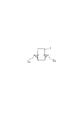
図1は本発明に係る留置機能を備えたICタグを示す実施例である。同図の1はICタグ、2a,2bは係止片を表し、ICタグ1は2本の係止片2a,2bを有している。ここで、ICタグ1はアンテナとLSIから成るチップで、外表面は樹脂で被覆された構造とし、このICタグに細いバネ性の係止片2a,2bが連結して延びている。そこで、このICタグ1を体内に挿入する場合、両係止片2a,2bは互いに内側へ撓んで縮まるが、所定の病変部位で停止するならば外方向へ広がり、ICタグ1はその位置に留置される。
FIG. 1 is an embodiment showing an IC tag having an indwelling function according to the present invention. In FIG. 1, 1 denotes an IC tag, 2a and 2b denote locking pieces, and the
図2は本発明の他の実施例であり、ICタグが逆V形をしている。すなわち、逆V形として先端が細く尖っていることで、体内への挿入はし易く、しかも所定の病変部位に達したならば、逆戻りすることなく留置する。ICタグ自体に留置機能を備える形状としては、図2の逆V形に限らず、三角形とすることも出来、さらには逆V形や三角形のICタグに上記係止片2a,2bを組み合わせた形態とすることも可能である。
FIG. 2 shows another embodiment of the present invention, in which the IC tag has an inverted V shape. That is, since the tip is thin and sharp as an inverted V shape, it is easy to insert into the body, and when it reaches a predetermined lesion site, it is placed without returning. The shape provided with the indwelling function in the IC tag itself is not limited to the inverted V shape shown in FIG. 2, but may be a triangle. Further, the locking
図3は本発明に係る留置機能を備えたICタグ1の更なる別形態を示している。このICタグ1にはゼンマイ3が備わっていて、所定の病変部位に挿入したICタグ1は該ゼンマイバネ3によって移動することなく留置される。ここで、ゼンマイバネの材質として、例えば形状記憶合金を使用するならば、同図(a)に示すように針穴にセットされている時に該ゼンマイバネ3はストレートに伸びているが、体内に挿入されて所定の温度(約36℃)に達したところで、変形して元の形状に復元することが出来る。すなわち、ゼンマイバネ3の形状に復元することで、挿入されたICタグの位置は変化せずに留置される。
FIG. 3 shows still another embodiment of the
ところで、本発明に係る留置機能を備えたICタグの用途は特に限定されるものではない。基本的には手術に際して術者が病変部を認識する為の標識手段として用いるもので、具体的には次の病変に適用出来る。
(1)大腸ガン
大腸ガンは大腸の内壁表面に発生する。この内壁に発生したガンは内視鏡にて発見され、該内視鏡を用いてICタグを大腸ガン又は大腸ガンの近傍に挿入・留置する。
(2)乳ガン
乳ガンは軟部組織に発生するが、そこで乳ガンをCT、エコーなどにて確認しながらICタグを挿入・留置し、ガン細胞を摘出する際の標識として利用できる。
(3)肺ガン
肺ガンの場合には、CTを使いながら体表から針を刺して、又は気管支から内視鏡やカテーテルを入れて、所定の病変部位にICタグを挿入・留置する。
(4)肝臓ガン
肝臓ガンの場合には、血管から細いチューブを挿入し、例えばエコーを使いながら所定の病変部位を特定し、この位置にICタグを挿入・留置する。又は、体表から針を刺してICタグを挿入・留置することが出来る。
(5)脳腫瘍
非常に細いチューブを血管に挿入し、CTを使いながら病変部を特定してICタグを該チューブから押出して留置することが出来る。
By the way, the application of the IC tag having the indwelling function according to the present invention is not particularly limited. Basically, it is used as a labeling means for an operator to recognize a lesion during surgery, and can be applied specifically to the next lesion.
(1) Colorectal cancer Colorectal cancer occurs on the inner wall surface of the large intestine. The cancer that has occurred on the inner wall is discovered by an endoscope, and an IC tag is inserted and placed in the vicinity of colon cancer or colon cancer using the endoscope.
(2) Breast cancer Although breast cancer occurs in soft tissues, it can be used as a label for inserting and placing an IC tag and extracting cancer cells while confirming breast cancer by CT, echo, or the like.
(3) Lung cancer In the case of lung cancer, a needle is inserted from the body surface using CT, or an endoscope or a catheter is inserted from the bronchus, and an IC tag is inserted and placed at a predetermined lesion site.
(4) Liver cancer In the case of liver cancer, a thin tube is inserted from a blood vessel, a predetermined lesion site is identified using, for example, an echo, and an IC tag is inserted and placed at this position. Alternatively, the IC tag can be inserted and placed by inserting a needle from the body surface.
(5) Brain tumor A very thin tube can be inserted into a blood vessel, a lesion can be identified using CT, and an IC tag can be pushed out of the tube and placed.
図4は大腸4にガン細胞5が発生した場合を示し、本発明に係るICタグ1をガン部位に留置することが出来る。ガン細胞5は大腸4の内壁6に発生するが、このガン細胞5は内視鏡7によって確認することが出来る。すなわち、肛門から内視鏡7を入れて検査すれば、大腸4の内壁6に発生したガン細胞5が確認される。ガン細胞5を確認したならば、ガン細胞5の中心部にICタグ1を押出し・挿入する。挿入されたICタグ1は係止片2a,2bによってその位置が定まり、針を抜いても逆戻りすることなく留置される。
FIG. 4 shows the case where
図5は内視鏡7の先端部を表しているが、同図の8a,8bは光源を示し、光ファイバー9a,9bを介して機器本体(図示なし)の光を照射することが出来、この光は反射してレンズ10から入射し、光ファイバー11を介して機器本体のディスプレイに拡大画像として表示する。術者はこの画像を見ながら針を近づけてICタグ1を押出し、所定の位置にICタグ1を挿入する。
FIG. 5 shows the distal end portion of the endoscope 7. Reference numerals 8a and 8b in FIG. 5 denote light sources, which can emit light from an apparatus main body (not shown) via optical fibers 9a and 9b. The light is reflected and incident from the
図6はICタグ1がセットされる針12を示している。この針12は術者の手元まで延びているチューブの先端と連結していて内視鏡7のチャンネル13に嵌って出し入れ可能な状態にあり、針穴15に収容されているプッシャー14を先端側へ移動するならば、該プッシャー14に押されてICタグ1は押出される。この場合、前記図4に示しているように、内視鏡7の先端から針12を突出してガン細胞5に刺し込み、この状態でプッシャー14が移動してICタグ1を押出す。ICタグ1はガン細胞5に挿入され、係止片2a,2bが広がって留置される。
FIG. 6 shows the
内視鏡7のチャンネル13に嵌っている針12は手元まで延びているチューブを操作することで該チャンネル13から出し入れすることが出来る。そして、プッシャー14は該チューブの穴に挿通した細いワイヤーと連結し、手元でワイヤーを操作して該プッシャー14を押出すことが出来る構造としている。勿論、本発明ではICタグ1を病変部又は病変部付近に挿入する手段は限定するものではない。
The
図4は針12が内視鏡7の先端からある程度突出して延びている状態であって、この針12をガン細胞5又はその近傍に刺し、この状態でプッシャー14にて押圧するならば、ICタグ1は針12の先端から押出されてガン細胞5内に埋着・留置される。前記図1に示すICタグ1の係止片2a,2bは両外方向へストレートに延びているが、針穴15内ではICタグ1の側辺に沿うように屈曲している。そして、針穴15から押出されると共に係止片2a,2bは復元して外方向へ真っ直ぐに伸び、係止片2a,2bがガン細胞5に係止し、針12を抜いても逆戻りすることはない。
FIG. 4 shows a state in which the
ここで、係止片2a,2bには細いバネ材が使用されている。又は形状記憶合金を用いることも出来る。すなわち、ガン細胞5に挿入されると同時に温度が36℃前後に上昇することで、ICタグ1の側辺に沿って屈曲している係止片2a,2bが元の形状に復元して両外方向へストレートに伸びることが出来る。
Here, a thin spring material is used for the
図2に示すICタグ1の場合も針穴15にセットされ、プッシャー14にて押出される。逆V形のICタグ1は全体又は両側部が円弧状に湾曲した状態で針穴15に嵌ってセットされる。そこで、プッシャー14によって針先端から押出されると同時に湾曲している形状が復元して平面状になり、針12が後退しても両先端が係止して逆戻りすることなく、その位置に留置される。
The
図3に示すゼンマイバネ3を備えたICタグ1は同じく針穴15にセットされる。この場合、ゼンマイバネ3はストレートに伸びた状態と成っていて、例えば、体内の血管に挿入されると同時にゼンマイバネ3に復元する。すなわち、ゼンマイバネ3には形状記憶合金が使用され、その温度が36℃前後に成った時にゼンマイバネ形状に復元することが出来、挿入されたその位置に留置される。
The
ところで、ICタグはアンテナとLSIが一体的に組み込まれたチップであるが、センサーから発信する弱い信号に対して反応できるように、特別なアンテナを設けることも可能である。 By the way, the IC tag is a chip in which an antenna and an LSI are integrated, but a special antenna can be provided so that it can react to a weak signal transmitted from the sensor.
1 ICタグ
2 係止片
3 ゼンマイバネ
4 大腸
5 ガン細胞
6 内壁
7 内視鏡
8 光源
9 光ファイバー
10 レンズ
11 光ファイバー
12 針
13 チャンネル
14 プッシャー
15 針穴
DESCRIPTION OF
10 lenses
11 Optical fiber
12 stitches
13 channels
14 Pusher
15 Needle hole
Claims (6)
Priority Applications (1)
| Application Number | Priority Date | Filing Date | Title |
|---|---|---|---|
| JP2008126663A JP2009273610A (en) | 2008-05-14 | 2008-05-14 | Ic tag with indwelling function |
Applications Claiming Priority (1)
| Application Number | Priority Date | Filing Date | Title |
|---|---|---|---|
| JP2008126663A JP2009273610A (en) | 2008-05-14 | 2008-05-14 | Ic tag with indwelling function |
Publications (1)
| Publication Number | Publication Date |
|---|---|
| JP2009273610A true JP2009273610A (en) | 2009-11-26 |
Family
ID=41439594
Family Applications (1)
| Application Number | Title | Priority Date | Filing Date |
|---|---|---|---|
| JP2008126663A Pending JP2009273610A (en) | 2008-05-14 | 2008-05-14 | Ic tag with indwelling function |
Country Status (1)
| Country | Link |
|---|---|
| JP (1) | JP2009273610A (en) |
Cited By (8)
| Publication number | Priority date | Publication date | Assignee | Title |
|---|---|---|---|---|
| WO2014185067A1 (en) * | 2013-05-17 | 2014-11-20 | パナソニックIpマネジメント株式会社 | Sensor-implanting device and sensor-implanting system |
| JP2018524059A (en) * | 2015-06-05 | 2018-08-30 | シアナ メディカル,インク. | Passive tag and system and method using the same |
| KR20190054237A (en) * | 2017-11-13 | 2019-05-22 | 재단법인 오송첨단의료산업진흥재단 | Attachable clip module using rfid for detecting a portion |
| WO2019156714A1 (en) * | 2018-02-06 | 2019-08-15 | Chase Arnold | Diversified glucose sensor system |
| WO2019175931A1 (en) * | 2018-03-12 | 2019-09-19 | 日特エンジニアリング株式会社 | Tag for embedment |
| US10827949B2 (en) | 2016-04-06 | 2020-11-10 | Cianna Medical, Inc. | Reflector markers and systems and methods for identifying and locating them |
| US11191445B2 (en) | 2015-06-05 | 2021-12-07 | Cianna Medical, Inc. | Reflector markers and systems and methods for identifying and locating them |
| US11883150B2 (en) | 2018-09-06 | 2024-01-30 | Cianna Medical, Inc. | Systems for identifying and locating reflectors using orthogonal sequences of reflector switching |
Citations (9)
| Publication number | Priority date | Publication date | Assignee | Title |
|---|---|---|---|---|
| US5853366A (en) * | 1996-07-08 | 1998-12-29 | Kelsey, Inc. | Marker element for interstitial treatment and localizing device and method using same |
| JP2001008947A (en) * | 1999-04-26 | 2001-01-16 | Junichi Shimada | Microtumor tracking operation |
| JP2001145646A (en) * | 1999-09-17 | 2001-05-29 | Pi Medical Inc | Embedding object and method for treating snore |
| US6336904B1 (en) * | 1998-04-07 | 2002-01-08 | Pro Duct Health, Inc. | Methods and devices for the localization of lesions in solid tissue |
| JP2002058648A (en) * | 2000-08-18 | 2002-02-26 | Jiinia & Aarei Kk | Observation apparatus for action of animal and movement of article |
| JP2003520057A (en) * | 1998-10-23 | 2003-07-02 | ユナイテッド ステイツ サージカル コーポレイション | Anatomy device |
| JP2004536660A (en) * | 2001-08-03 | 2004-12-09 | タイコ ヘルスケア グループ エルピー | Tissue marking device and method |
| JP2007203092A (en) * | 2001-01-02 | 2007-08-16 | Therasense Inc | Insertion kit |
| JP2007229490A (en) * | 2001-08-29 | 2007-09-13 | Rare Metal:Kk | Tag device usable for living body internal information detection system |
-
2008
- 2008-05-14 JP JP2008126663A patent/JP2009273610A/en active Pending
Patent Citations (9)
| Publication number | Priority date | Publication date | Assignee | Title |
|---|---|---|---|---|
| US5853366A (en) * | 1996-07-08 | 1998-12-29 | Kelsey, Inc. | Marker element for interstitial treatment and localizing device and method using same |
| US6336904B1 (en) * | 1998-04-07 | 2002-01-08 | Pro Duct Health, Inc. | Methods and devices for the localization of lesions in solid tissue |
| JP2003520057A (en) * | 1998-10-23 | 2003-07-02 | ユナイテッド ステイツ サージカル コーポレイション | Anatomy device |
| JP2001008947A (en) * | 1999-04-26 | 2001-01-16 | Junichi Shimada | Microtumor tracking operation |
| JP2001145646A (en) * | 1999-09-17 | 2001-05-29 | Pi Medical Inc | Embedding object and method for treating snore |
| JP2002058648A (en) * | 2000-08-18 | 2002-02-26 | Jiinia & Aarei Kk | Observation apparatus for action of animal and movement of article |
| JP2007203092A (en) * | 2001-01-02 | 2007-08-16 | Therasense Inc | Insertion kit |
| JP2004536660A (en) * | 2001-08-03 | 2004-12-09 | タイコ ヘルスケア グループ エルピー | Tissue marking device and method |
| JP2007229490A (en) * | 2001-08-29 | 2007-09-13 | Rare Metal:Kk | Tag device usable for living body internal information detection system |
Cited By (14)
| Publication number | Priority date | Publication date | Assignee | Title |
|---|---|---|---|---|
| US10194939B2 (en) | 2013-05-17 | 2019-02-05 | Panasonic Intellectual Property Management Co., Ltd. | Sensor embedding device and sensor embedding system |
| JP5896322B2 (en) * | 2013-05-17 | 2016-03-30 | パナソニックIpマネジメント株式会社 | Sensor embedding device and sensor embedding system |
| WO2014185067A1 (en) * | 2013-05-17 | 2014-11-20 | パナソニックIpマネジメント株式会社 | Sensor-implanting device and sensor-implanting system |
| US11191445B2 (en) | 2015-06-05 | 2021-12-07 | Cianna Medical, Inc. | Reflector markers and systems and methods for identifying and locating them |
| JP2018524059A (en) * | 2015-06-05 | 2018-08-30 | シアナ メディカル,インク. | Passive tag and system and method using the same |
| US11351008B2 (en) | 2015-06-05 | 2022-06-07 | Cianna Medical, Inc. | Passive tags, and systems and methods for using them |
| US10827949B2 (en) | 2016-04-06 | 2020-11-10 | Cianna Medical, Inc. | Reflector markers and systems and methods for identifying and locating them |
| US11484219B2 (en) | 2016-04-06 | 2022-11-01 | Cianna Medical, Inc. | Reflector markers and systems and methods for identifying and locating them |
| KR20190054237A (en) * | 2017-11-13 | 2019-05-22 | 재단법인 오송첨단의료산업진흥재단 | Attachable clip module using rfid for detecting a portion |
| KR102016960B1 (en) | 2017-11-13 | 2019-09-02 | 재단법인 오송첨단의료산업진흥재단 | Attachable clip module using rfid for detecting a portion |
| WO2019156714A1 (en) * | 2018-02-06 | 2019-08-15 | Chase Arnold | Diversified glucose sensor system |
| US11730403B2 (en) | 2018-02-06 | 2023-08-22 | Arnold Chase | Diversified glucose sensor system |
| WO2019175931A1 (en) * | 2018-03-12 | 2019-09-19 | 日特エンジニアリング株式会社 | Tag for embedment |
| US11883150B2 (en) | 2018-09-06 | 2024-01-30 | Cianna Medical, Inc. | Systems for identifying and locating reflectors using orthogonal sequences of reflector switching |
Similar Documents
| Publication | Publication Date | Title |
|---|---|---|
| JP2009273610A (en) | Ic tag with indwelling function | |
| CN107072736B (en) | Computed tomography enhanced fluoroscopy systems, devices, and methods of use thereof | |
| JP2020163217A (en) | Apparatus, systems, and methods for localizing markers or tissue structures within a body | |
| US7935048B2 (en) | Method and system for navigating within a flexible organ of the body of a patient | |
| US20080154090A1 (en) | Endoscopic System for In-Vivo Procedures | |
| JP4166277B2 (en) | Medical method and apparatus using in-vivo probe | |
| CN103648416B (en) | System for fiducial deployment | |
| US20050192478A1 (en) | System and method for endoscopic optical constrast imaging using an endo-robot | |
| US8989844B2 (en) | Imaging system for following a surgical tool in an operation field | |
| EP2249737B1 (en) | Biopsy guidance by electromagnetic tracking and photonic needle | |
| US7074189B1 (en) | Endoscopically deliverable ultrasound imaging system and method of use | |
| JP2010000284A (en) | Surgical procedure using ic tag | |
| Law et al. | Endoscopic ultrasound (EUS)-guided fiducial placement allows localization of small neuroendocrine tumors during parenchymal-sparing pancreatic surgery | |
| WO2006072947A2 (en) | Endoscopic system for in-vivo procedures | |
| JPH10508504A (en) | Method and apparatus for identifying and marking tissue | |
| JPH10108827A (en) | Infrared ray system for visualizing body portion | |
| CN107427202B (en) | Device, system and method for illuminating a structure of interest inside a human or animal body | |
| CN111465351A (en) | Ultrasonic localization system with advanced biopsy site markers | |
| US20050090711A1 (en) | System for locating lesions in hollow organs | |
| JPWO2012102099A1 (en) | Treatment tool | |
| WO2009050667A1 (en) | Tumor demarcation using targeted fluorescent probe and photonic needle | |
| JP7283778B2 (en) | Imaging system and method | |
| JP5833776B2 (en) | Fiducial deployment system | |
| JP2003290127A (en) | Sentinel lymph node-detecting method | |
| JP2005204694A (en) | Identifying system of lesion in digestive organ |
Legal Events
| Date | Code | Title | Description |
|---|---|---|---|
| A621 | Written request for application examination |
Free format text: JAPANESE INTERMEDIATE CODE: A621 Effective date: 20110513 |
|
| A521 | Written amendment |
Free format text: JAPANESE INTERMEDIATE CODE: A523 Effective date: 20120723 |
|
| A131 | Notification of reasons for refusal |
Free format text: JAPANESE INTERMEDIATE CODE: A131 Effective date: 20121106 |
|
| A02 | Decision of refusal |
Free format text: JAPANESE INTERMEDIATE CODE: A02 Effective date: 20130618 |