JP2009257554A - Manifold for solenoid valve - Google Patents
Manifold for solenoid valve Download PDFInfo
- Publication number
- JP2009257554A JP2009257554A JP2008110437A JP2008110437A JP2009257554A JP 2009257554 A JP2009257554 A JP 2009257554A JP 2008110437 A JP2008110437 A JP 2008110437A JP 2008110437 A JP2008110437 A JP 2008110437A JP 2009257554 A JP2009257554 A JP 2009257554A
- Authority
- JP
- Japan
- Prior art keywords
- manifold
- discharge
- supply
- communication passage
- manifolds
- Prior art date
- Legal status (The legal status is an assumption and is not a legal conclusion. Google has not performed a legal analysis and makes no representation as to the accuracy of the status listed.)
- Pending
Links
Images


Abstract
Description
本発明は、複数の電磁弁を装着するためのマニホールドを一対の同一部品のダイカスト成形によって構成し、また、任意数の電磁弁を装着するためのマニホールドを、2種の部品のダイカスト成形によって構成できるようにした電磁弁用マニホールドに関するものである。 In the present invention, a manifold for mounting a plurality of solenoid valves is configured by die casting of a pair of identical parts, and a manifold for mounting an arbitrary number of solenoid valves is configured by die casting of two types of parts. The present invention relates to a solenoid valve manifold that can be made.
電磁弁を装着するための一つの弁装着面を有するマニホールドの任意数を連接して多連の電磁弁用マニホールドとすることは、例えば、特許文献1に開示されているように、従来から知られている。
この多連の電磁弁用マニホールドにおいては、マニホールドの連接方向の一端または両端に外部配管を接続する端部連結部材を設けて、各マニホールドの一括圧力流体給排用の流路に圧力流体の給排を行うように構成しているが、電磁弁を搭載するマニホールドが全て共通のものであっても、両端の連結部材を含めて少なくとも3種の部品を接続する必要があり、従ってそれらの部品を製造、保管する必要がある。そのため、部品の種類をできるだけ少なくすることが望まれる。
For example, as disclosed in
In this multiple solenoid valve manifold, an end connecting member for connecting an external pipe is provided at one or both ends in the manifold connecting direction, and pressure fluid is supplied to the collective pressure fluid supply / discharge passage of each manifold. Although it is configured to exhaust, it is necessary to connect at least three types of parts including the connecting members at both ends even if all the manifolds on which the solenoid valves are mounted are common. Must be manufactured and stored. Therefore, it is desirable to reduce the number of parts as much as possible.
また、各マニホールドの上面の弁装着面には、電磁弁の各接続ポートに対応させて複数の給排用の通孔が列設されるが、電磁弁は近年著しく小型化されているため、それに設けられている複数の接続ポートは、そのポート間の間隔が非常に短くなり、一方、端部連結部材に設ける外部配管の継手間の間隔は、規格化された径の配管接続を行うため、電磁弁の上記各接続ポート間の間隔よりも著しく大きいものであり、そのため、上記外部配管の継手に連なる端部連結部材及びマニホールドにおける一括圧力流体給排用の流路も、大径で流路間隔が大きいものになる。 In addition, on the valve mounting surface on the upper surface of each manifold, there are a plurality of supply / discharge holes arranged corresponding to each connection port of the solenoid valve, but since the solenoid valve has been remarkably miniaturized in recent years, The plurality of connection ports provided on it have a very short interval between the ports, while the interval between the joints of the external piping provided on the end connecting member is to connect the pipes with a standardized diameter. Therefore, the interval between the connection ports of the solenoid valve is remarkably larger than that of the connection port. Therefore, the end connecting member connected to the joint of the external pipe and the flow path for supplying and discharging the collective pressure fluid in the manifold also have a large diameter. The road spacing will be large.
そこで、電磁弁を搭載するマニホールド内において、上記一括圧力流体給排用の流路と電磁弁の各ポートに対応させる複数の給排用の通孔を相互に連通させようとすると、その流路が複雑になったり、電磁弁装着面から斜めに穿設した孔になったりし、それらの製造過程が複雑化してしまう。また、例えば、特許文献2に開示されているように、隣接する一括圧力流体給排用の流路の位置を上下にずらして設けることにより、電磁弁の各ポートに対応させる複数の給排用の通孔から一括圧力流体給排用の流路に至る通路を電磁弁装着面からの垂直の孔によって形成すると、上記通孔を形成するための穿孔等の製造過程が単純化されるが、マニホールド自体が上下に大型化するという問題がある。
本発明の技術的課題は、複数の電磁弁を装着するためのマニホールドを一対の同一部品のダイカスト成形によって構成し、また、任意数の電磁弁を装着するためのマニホールドを、2種の部品のダイカスト成形によって構成できるようにした電磁弁用マニホールドを提供することにある。
本発明の更に具体的な技術的課題は、マニホールド内における流路形成の改善により、一括供給用流路及びその両側の一括排出用流路のように設置間隔が広いものと、それよりも設置間隔が非常に狭い、電磁弁に連通させるための個別供給用通孔とその両側の個別排出用通孔等を、上記弁装着面に対して垂直に形成された上記連通路によって連通させ、マニホールドを構成する部品のダイカスト成形を容易にすることにある。
The technical problem of the present invention is that a manifold for mounting a plurality of solenoid valves is formed by die casting of a pair of identical parts, and a manifold for mounting any number of solenoid valves is made up of two types of parts. An object of the present invention is to provide a solenoid valve manifold which can be constructed by die casting.
A more specific technical problem of the present invention is that, by improving the flow path formation in the manifold, a larger installation interval such as a collective supply flow path and a collective discharge flow path on both sides of the flow path is installed. An individual supply through hole for communicating with a solenoid valve and an individual discharge through hole on both sides thereof are communicated with each other through the communication passage formed perpendicular to the valve mounting surface. Is to facilitate die-casting of the components constituting the.
上記課題を解決するため、本発明は、同一形状の一対のダイカスト成形されたエンドマニホールドを備え、それぞれのエンドマニホールドが、そのボディに、相互に連接可能な第1連接面と、該第1連接面に背向する配管接続面と、上面に形成された電磁弁を装着するための第1弁装着面とを有し、上記配管接続面に開口する断面円形の一括供給用流路と上記第1連接面に開口して上記弁装着面の内部まで延びる断面縦長の第1供給用連通路、及び上記一括供給用流路の両側の断面円形の一括排出用流路と上記第1連接面における第1供給用連通路の両側に開口してそれぞれ上記第1弁装着面の内部まで延びる断面横長の第1排出用連通路とが、上記ボディ内において相互に連通すると共に、上記第1弁装着面に開口する個別供給用通孔及びその両側の個別排出用通孔が、上記第1供給用連通路及びその両側の第1排出用連通路にそれぞれ連通しており、上記配管接続面に開口する各流路、上記第1連接面に開口する各連通路、及び上記第1弁装着面に開口する各通孔は、ボディにおけるそれらを設けた面に対して垂直で直線的に延びるものとして形成され、上記第1弁装着面の個別供給用通孔とその両側の個別排出用通孔との間隔は、上記配管接続面における一括供給用流路と一括排出用流路との間隔よりも狭く、上記第1供給用連通路の両側に位置する断面横長の両第1排出用連通路が、それぞれ、両側の一括排出用流路及び個別排出用通孔の両者に連通する横長形状に形成されていることを特徴とするものである。 In order to solve the above problems, the present invention includes a pair of die-cast end manifolds having the same shape, each end manifold having a first connecting surface that can be connected to the body, and the first connecting surface. A pipe connection surface facing away from the surface and a first valve mounting surface for mounting a solenoid valve formed on the upper surface, and a collective supply flow path having a circular cross section that opens to the pipe connection surface and the first A first supply communication passage having a vertically long cross section that opens to one connection surface and extends to the inside of the valve mounting surface; a collective discharge flow channel having a circular cross section on both sides of the collective supply flow channel; and the first connection surface A first discharge communication passage having a horizontally long cross section that opens to both sides of the first supply communication passage and extends to the inside of the first valve mounting surface communicates with each other within the body, and the first valve mounting Individual feed through holes open on the surface The individual discharge through holes on both sides of the pipes communicate with the first supply communication passage and the first discharge communication passages on both sides thereof, respectively, and each flow path opened to the pipe connection surface, the first connection surface The communication passages that open to each other and the through holes that open to the first valve mounting surface are formed so as to extend linearly and perpendicularly to the surface of the body where they are provided. The interval between the individual supply through holes and the individual discharge through holes on both sides thereof is narrower than the interval between the collective supply flow path and the collective discharge flow path on the pipe connection surface. Both the first discharge communication passages having a horizontally long cross section located on both sides are formed in a horizontally long shape communicating with both the collective discharge flow path and the individual discharge through holes on both sides, respectively. is there.
上記構成を有する電磁弁用マニホールドは、上記一対のエンドマニホールドの第1連接面間に挟着されるダイカスト成形された中間マニホールドを備え、この中間マニホールドが、そのボディの対向両面にあって上記エンドマニホールドの第1連接面に連接可能な第2連接面と、上面に形成された電磁弁を装着するための第2弁装着面とを有し、上記両第2連接面間に、上記エンドマニホールドの第1連接面に開口する第1供給用連通路及びその両側の第1排出用連通路と同形同配置で直線的に延びる第2供給用連通路及び第2排出用連通路を設けると共に、上記第2弁装着面に開口する個別供給用通孔とその両側の個別排出用通孔との間隔を、エンドマニホールドの第1弁装着面におけるそれらの通孔の間隔と同一にし、且つ、それらの通孔の第2供給用連通路及び第2排出用連通路に対する連通位置を、エンドマニホールドにおけるそれらの通孔の連通位置と同一にしたものとすることができる。 The solenoid valve manifold having the above-described configuration includes a die-cast intermediate manifold sandwiched between the first connecting surfaces of the pair of end manifolds. A second connecting surface connectable to the first connecting surface of the manifold, and a second valve mounting surface for mounting an electromagnetic valve formed on the upper surface, and the end manifold is disposed between the second connecting surfaces. And a second supply communication passage and a second discharge communication passage extending linearly in the same shape and arrangement as the first supply communication passage opening on the first connection surface and the first discharge communication passages on both sides thereof. The interval between the individual supply through-holes opening on the second valve mounting surface and the individual discharge through-holes on both sides thereof is the same as the interval between those through-holes on the first valve mounting surface of the end manifold, and Those Second communication position relative to the supply communication passage and the second discharge communication passage may be provided with the same communication position thereof through holes in the end manifold.
本発明に係る電磁弁用マニホールドの好ましい実施形態においては、上記中間マニホールドが、その複数を相互に連接可能な第2連接面において連接した中間マニホールド連接体として構成され、その中間マニホールド連接体の両端側の第2連接面を上記一対のエンドマニホールドの第1連接面間に挟着させることにより多連のマニホールドとして構成される。 In a preferred embodiment of the manifold for solenoid valves according to the present invention, the intermediate manifold is configured as an intermediate manifold connecting body that is connected to a plurality of second connecting surfaces that can be connected to each other. The second connecting surface on the side is sandwiched between the first connecting surfaces of the pair of end manifolds to constitute a multi-unit manifold.
また、本発明に係る電磁弁用マニホールドの好ましい実施形態においては、一対のエンドマニホールドにおける第1連接面の第1供給用連通路相互、及び第1排出用連通路相互の連結部、一対の中間マニホールドにおける第2連接面の第2供給用連通路相互、及び第2排出用連通路相互の連結部、あるいは、エンドマニホールドにおける第1連接面の第1供給用連通路及び第1排出用連通路と、中間マニホールドにおける第2連接面の第2供給用連通路及び第2排出用連通路の連結部を、それらの各連通路端の周囲に凹設した装着溝間にシール用のブッシュを密に嵌入することによりシールされる。
この場合に、第1供給用連通路と第1排出用連通路、及び第2供給用連通路と第2排出用連通路とを縦横に向きが異なる同一断面形状に形成し、それらの全ての連結部に同一のシール用ブッシュを用いるのが望ましい。
Further, in a preferred embodiment of the solenoid valve manifold according to the present invention, the first supply communication passages on the first connecting surfaces of the pair of end manifolds, the connection portion between the first discharge communication passages, and the pair of intermediate portions. A connection part between the second supply communication paths and the second discharge communication paths on the second connection surface in the manifold, or a first supply communication path and a first discharge communication path on the first connection surface in the end manifold. And a sealing bush between the connecting portions of the second supply communication path and the second discharge communication path on the second connection surface of the intermediate manifold between the mounting grooves recessed around the respective communication path ends. It is sealed by being inserted into.
In this case, the first supply communication path and the first discharge communication path, and the second supply communication path and the second discharge communication path are formed in the same cross-sectional shape with different directions in the vertical and horizontal directions, and all of them are formed. It is desirable to use the same sealing bush for the connecting portion.
本発明に係る上記電磁弁用マニホールドにおいては、連結する両連通路端の各周囲に凹設した装着溝間に嵌入するシール用のブッシュを、上記連通路と同形の内孔を有し、且つ該装着溝に嵌入する周面にそれぞれOリングを嵌合した2個の環状溝を有するものとし、それぞれのOリングによって、連結する両連通路端の環状溝の内周壁とブッシュの外面との間をシールさせたものとすることができる。 In the solenoid valve manifold according to the present invention, the sealing bushing fitted between the mounting grooves recessed around each of the communicating path ends to be connected has an inner hole having the same shape as the communicating path, and It is assumed that there are two annular grooves each fitted with an O-ring on the peripheral surface to be fitted in the mounting groove, and the inner peripheral wall of the annular groove at both communication path ends to be connected to the outer surface of the bush by each O-ring. The gap can be sealed.
また、上記本発明に係る電磁弁用マニホールドにおいては、エンドマニホールド及び中間マニホールドにおける連接面に近接する両側側面に、内奥を連接面側に傾斜させたクリップ収容溝を、その下端から上端面までは達しない範囲に設けることにより、該クリップ収容溝と連接面との間に係合突部を形成し、相互に当接した連接面の両側部においてそれぞれ重ね合わされた二つの係合突部を、両端に折曲部を有する一対の接続クリップの該折曲部で弾性的に挟持させることにより、エンドマニホールド相互、中間マニホールド相互、またはエンドマニホールドと中間マニホールドを連結することができる。 Further, in the solenoid valve manifold according to the present invention, the clip receiving groove whose inner back is inclined toward the connecting surface side is formed on both side surfaces close to the connecting surface in the end manifold and the intermediate manifold from the lower end to the upper end surface. By providing in a range that does not reach, an engagement protrusion is formed between the clip receiving groove and the connection surface, and two engagement protrusions that are overlapped on both sides of the connection surface that are in contact with each other are formed. The end manifolds, the intermediate manifolds, or the end manifolds and the intermediate manifolds can be coupled by elastically holding the bent parts of the pair of connection clips having the bent parts at both ends.
上述した本発明によれば、任意数の電磁弁を装着するためのマニホールドを、2種の部品のダイカスト成形によって構成できるようにした電磁弁用マニホールドを提供することができ、更に、マニホールド内における流路形成の改善により、一括供給用流路及びその両側の一括排出用流路のように設置間隔が広いものと、それよりも設置間隔が非常に狭い、電磁弁に連通させるための個別供給用通孔とその両側の個別排出用通孔等を、上記弁装着面に対して垂直に形成された上記連通路によって連通させ、マニホールドを構成する部品のダイカスト成形を容易にすることができる。 According to the above-described present invention, a manifold for mounting an arbitrary number of solenoid valves can be provided by a die-cast molding of two types of parts, and a solenoid valve manifold can be provided in the manifold. Due to improved flow path formation, individual supply to communicate with solenoid valves that have a wide installation interval, such as a collective supply flow path and a collective discharge flow path on both sides of the flow path, and a very narrow installation interval. The through holes and the individual discharge through holes on both sides thereof can be communicated with each other by the communication passage formed perpendicular to the valve mounting surface, thereby facilitating die-casting of parts constituting the manifold.
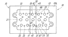
本発明に係る電磁弁用マニホールドは、図1及び図2に例示するように、少なくとも同一形状の一対のダイカスト成形されたエンドマニホールド10を備え、それらは、それぞれ二つの電磁弁を搭載できる2連のマニホールドとして構成しているので、その連接によって四つの電磁弁を搭載できる4連のマニホールドとして構成できるものである。また、電磁弁を搭載するマニホールドの連数を増加させるためには、図2及び図5に明瞭に示しているように、上記一対のエンドマニホールド10の間に挟着する中間マニホールド30が用いられる。
As illustrated in FIGS. 1 and 2, the manifold for solenoid valves according to the present invention includes at least a pair of die-
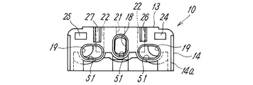
上記一対のエンドマニホールド10は、図1〜図7から分かるように、それらのボディ10aに、それぞれ、相互に連接可能な第1連接面11と、該第1連接面11に背向する配管接続面12と、図示しない電磁弁を並置して装着するための上面の平坦な第1弁装着面13とを有している。上記配管接続面12は、図5及び図6に示すように、断面円形の一括供給用流路15及びその両側に断面円形の一対の一括排出用流路16を開口させたもので、それらの各流路に外部配管を接続するための管継手を連結可能に形成している。また、図5及び図7に示すように、上記第1連接面11には、上記第1弁装着面13の内部まで延びる断面縦長の第1供給用連通路18、及びその両側において同様に上記第1弁装着面13の内部まで延びる一対の断面横長の第1排出用連通路19を開口させている。
As can be seen from FIGS. 1 to 7, the pair of
更に、上記第1弁装着面13には、電磁弁の供給ポートに連通させる中央の個別供給用通孔21、及びその両側に電磁弁の排出ポートに連通させる一対の個別排出用通孔22を設けている。なお、この第1弁装着面13には、電磁弁を取り付けるためのねじ穴23を開設している。
Further, the first
上記配管接続面12に開口する一括供給用流路15と上記第1連接面11に開口する断面縦長の第1供給用連通路18、及び上記配管接続面12の一対の一括排出用流路16と上記第1連接面11に開口する断面横長の第1排出用連通路19とは、エンドマニホールド10のボディ10a内においてそれらの内端を相互に連通させ、上記第1弁装着面13における個別供給用通孔21を第1供給用連通路18に、また上記個別排出用通孔22を第1供給用連通路18の両側の第1排出用連通路19にそれぞれ連通させている。
そして、上記配管接続面12に開口する各流路15,16、上記第1連接面11に開口する各連通路18,19、及び上記第1弁装着面13に開口する各通孔21,22は、ダイカストによる成形を容易にするため、ボディ10aにおけるそれらを設けた面に対して垂直で直線的に延びるものとして形成している。
The collective
And each
上記第1弁装着面13における個別供給用通孔21とその両側の個別排出用通孔22との間の間隔は、近年、電磁弁が非常に小型化されてそれらの複数の接続ポート間の間隔が非常に短くなっていることから、上記配管接続面12における一括供給用流路15と一括排出用流路16との間隔よりも非常に狭く形成する必要があり、そのため上記配管接続面12から一括供給用流路15及び一括排出用流路16を第1連接面11まで貫通させて、それに、第1弁装着面13に開口する個別供給用通孔21及び個別排出用通孔22を連通させようとすると、該通孔22を第1弁装着面13から一括排出用流路16に向けて斜めに開設する必要があり、エンドマニホールドのダイカスト成形が困難になる。
In recent years, the interval between the individual supply through
そこで、上記電磁弁用マニホールドにおいては、上記第1連接面11から第1弁装着面13の内部まで延びる断面縦長の長円形の第1供給用連通路18、及びその両側において同様に第1弁装着面13の内部まで延びる断面横長の長円形の第1排出用連通路19を設けて、第1弁装着面13から垂直に開設した個別供給用通孔21及び個別排出用通孔22をそれらに連通可能とし、特に、上記第1供給用連通路18は縦長にすることにより、その両側に位置する一対の第1排出用連通路19を、配管接続面12に開口する一対の一括排出用流路16と十分な流路断面で連通させながら、個別排出用通孔22の下まで延ばした横長形状に形成できるようにしている。
なお、図では、上記第1供給用連通路18及び一対の第1排出用連通路19の断面形状を、離間した2つの半円間を2本の直線で結んだ形状としているが、長径と短径とを有する楕円その他の縦または横に長い断面形状にすることができる。
In view of this, in the solenoid valve manifold, the first
In the drawing, the cross-sectional shapes of the first
一対のエンドマニホールド10における第1連接面11は、それらを相互に連接可能にするため、図5及び図7から分かるように、縦長の上記第1供給用連通路18を中央において左右対称形に形成すると共に、一対の第1排出用連通路19を同様に中心線の両側において左右対称形に形成し、また、連接する第1連接面11の位置決め用の凸部24と凹部25とを同様に左右対称の位置に設け、更に、第1弁装着面13に取り付ける電磁弁を可及的に第1連接面11に近づけて固定し、それによって全体的な形状を小型にするために、該第1連接面11からの突出部26に電磁弁固定用のねじ穴23を設けているが、その突出部26を受け入れる凹窪部27を該突出部26と対称の位置に設けている。この突出部26及び凹窪部27は、両第1連接面11の位置決め用にも機能するものである。
As can be seen from FIGS. 5 and 7, the first connecting
上記構成を有する電磁弁用マニホールドにおける一対のエンドマニホールド10においては、それらに搭載する電磁弁の連数を増大させるためには、図2〜図5に示しているように、一対の第1連接面11間に挟着できるダイカスト成形された中間マニホールド30が用いられる。
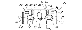
この中間マニホールド30は、そのボディ30aの対向両面にあって上記エンドマニホールド10の第1連接面11に連接可能な第2連接面31と、上面に形成された電磁弁を装着するための第2弁装着面33とを有している。
In the pair of
The
そして、図5及び図8に示すように、上記両第2連接面31間に、ボディ30aを貫通させて、エンドマニホールド10の第1供給用連通路18及びその両側の第1排出用連通路19とそれぞれ同形同配置で直線的に延びる第2供給用連通路38及びその両側の一対の第2排出用連通路39を設けている。第2供給用連通路38及び第2排出用連通路39が両第2連接面31に対して垂直に開設されているのは勿論である。
As shown in FIGS. 5 and 8, the
また、上記第2弁装着面33には、エンドマニホールド10の第1弁装着面13における通孔21,22と同じ間隔で同じ配置の個別供給用通孔41及びその両側の個別排出用通孔42を開口させ、且つ、それらの通孔41,42の第2供給用連通路38及び第2排出用連通路39に対する連通位置を、エンドマニホールド10におけるそれらの通孔21,22の連通路18,19に対する連通位置と同一にしている。上記通孔41,42も第2弁装着面33に対して垂直に開設されている。
The second
更に、上記一対の第2連接面31には、エンドマニホールド10の第1連接面11における位置決め用の凸部24と凹部25と同じ位置に同じ形状の凸部44及び凹部45を設け、また、エンドマニホールド10の電磁弁を取り付けるためのねじ穴23に対応する位置にねじ穴43を設け、エンドマニホールド10の突出部26及びそれを受け入れる凹窪部27と同じ位置に、同じ形状の突出部46及び凹窪部47を設けている。
従って、上記中間マニホールド30は、そのボディ30aの対向両面にある第2連接面31が他の中間マニホールド30の第2連接面31に連接可能であると共に、エンドマニホールド10の第1連接面11にも連接可能であり、そのため、複数の中間マニホールド30におけるボディ30aにある第2連接面31相互を連接することにより、中間マニホールド連接体とし、この中間マニホールド連接体の両端側の第2連接面31を上記一対のエンドマニホールド10の第1連接面11間に挟着させることにより、任意の多連のマニホールドとすることができる。
なお、上記エンドマニホールド10は必ずしも2連である必要はなく、また上記中間マニホールド30は必ずしも図示する1連のものとする必要はない。
Further, the pair of second connecting
Therefore, the
It should be noted that the
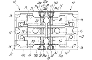
図1に示すように、一対のエンドマニホールド10の第1連接面11相互を連接し、それに伴って該連接面11に開口している長円形断面の第1供給用連通路18及び第1排出用連通路19を相互に連通させる場合に、あるいは、一対の中間マニホールド30における第2連接面31を相互に連接してその連接面31に開口している長円形断面の第2供給用連通路38及び第2排出用連通路39を相互に連通させる場合、更に、図2に示すように、エンドマニホールド10の第1連接面11と中間マニホールド30における第2連接面31とを連接し、それに伴って上記第1連接面11に開口している第1供給用連通路18及び第1排出用連通路19と、前記第2連接面31に開口している第2供給用連通路38及び第2排出用連通路39とを連通させる場合に、それらの各連通路の連結部における流体の漏洩を防止するため、上記長円形断面の各連通路を、縦横に向きが異なるにしても同一断面形状に形成し、それらの全ての連通路端の周囲に凹設した同形の装着溝51間に、図4、図5、図11及び図12に示すような同一のシール用ブッシュ50を密に嵌入するようにしている。
As shown in FIG. 1, a first
上記ブッシュ50はプラスチック製で、連結すべき連通路と同形の内孔52を有し、且つ、外周面に、連結すべき各連通路端の周囲に凹設した装着溝51のそれぞれに嵌入させるためのOリング54を嵌合した2個の環状溝53を有するものとして構成され、それぞれのOリング54により、連結する両連通路端の装着溝51の内周壁とブッシュ50の外面との間をシールさせている。上記ブッシュ50の環状溝53は、外周面の両側のフランジ部55,56と中央の環状突出部57との間に形成されたものである。
The
一対のエンドマニホールド10の第1連接面11相互を連接し、また、一対の中間マニホールド30における第2連接面31を相互に連接し、更に、エンドマニホールド10の第1連接面11と中間マニホールド30における第2連接面31とを連接するに当たっては、図3及び図4に示すような接続クリップ59を用いるのが望ましい。
この接続クリップ59による固定のため、上記エンドマニホールド10の第1連接面11に近接するボディ10aの両側側面14、及び中間マニホールド30における第2連接面31に近接するボディ30aの両側側面34には、内奥を連接面11,31側に傾斜させたクリップ収容溝14a,34aを、その側面14,34の下端から上端面までは達しない範囲に設けることにより、該クリップ収容溝14a,34aと連接面11,31との間に係合突部14b,34bを形成している。
The first connecting
For fixing by the
ここで用いる接続クリップ59は、図4に示すように、弾性を有する金属製でその両端部に、互いに接近する方向に傾斜するよう折曲された折曲部59aが形成されたものである。
そして、相互に当接した連接面11または31の両側部において、それぞれ重ね合わされた二つの係合突部14b,34bを、一対の接続クリップ59の該折曲部59aで弾性的に挟持させることにより、ボディ10aまたはボディ30a相互、あるいは、ボディ10aとボディ30aとが固定されるようにしている。上記クリップ収容溝14a,34aは、ボディ10a及びボディ30aの側面の下端から上端面までは達しない範囲に設けているので、ボディ10a及びボディ30aの下面側からクリップ収容溝14a,34aに接続クリップ59を圧入することにより連接したボディを固定することができ、それにより、エンドマニホールド10相互、中間マニホールド30相互、またはエンドマニホールド10と中間マニホールド30とが連結される。
As shown in FIG. 4, the
Then, the two engaging
上記構成を有するエンドマニホールド10または中間マニホールド30の各一対を連接し、あるいはエンドマニホールド10と中間マニホールドとを連接するに際し、一対のエンドマニホールド10の第1連接面11を相互に接合させると、該第1連接面11に開口する第1供給用連通路18及び第1排出用連通路19が相互に連通すると同時に、該連接面11に設けた位置決め用の凸部24と凹部25とが相互に嵌り合い、また、ねじ穴23を設けるために第1連接面11から突出させているの突出部26と、その突出部26に対応する凹窪部27が相互に嵌り合い、それらによって両第1連接面11の位置決めが行われて、両連接面11が密接状態で接合される。中間マニホールド30の各一対の連接、あるいはエンドマニホールド10と中間マニホールドとの連接についても同様である。
When each pair of the
また、上記エンドマニホールド10及び中間マニホールド30は、ダイカスト鋳造法により成形されるが、前述したように、エンドマニホールド10のボディ10aに開設した各流路15,16、各連通路18,19、及び各通孔21,22、並びに、中間マニホールド30のボディ30aにおける同様な連通路及び通孔は、いずれも基本的に直方体状をなすボディ10a,30aのそれらを設けた面に対して垂直で直線的に延びるものとし、斜め方向の孔のように、ダイカストの型抜きが困難、あるいは成形が煩雑になるような形態に形成していないので、それらのダイカストによる成形を容易にし、且つ低コストで行うことができ、厚肉部分は肉抜きによる軽量化を図ることもでき、また、一定断面の押出し材に対して多くの孔加工を行うことによりマニホールドを製造する場合のように、素材に対する機械加工が多くなることはなく、ダイカスト成形後の僅かな機械加工で最終的な製品とすることができる。上記ダイカスト成形に用いる金属として、通常、アルミニウム合金等が用いられる。
The
10 エンドマニホールド
10a ボディ
11 第1連接面
12 配管接続面
13 第1弁装着面
14,34 側面
14a,34a クリップ収容溝
14b,34b 係合突部
15 一括供給用流路
16 一括排出用流路
18 第1供給用連通路
19 第1排出用連通路
21 個別供給用通孔
22 個別排出用通孔
30 中間マニホールド
30a ボディ
31 第2連接面
33 第2弁装着面
38 第2供給用連通路
39 第2排出用連通路
41 個別供給用通孔
42 個別排出用通孔
50 ブッシュ
51 装着溝
52 内孔
53 環状溝
54 Oリング
59 接続クリップ
59a 折曲部
DESCRIPTION OF
Claims (7)
それぞれのエンドマニホールドが、そのボディに、相互に連接可能な第1連接面と、該第1連接面に背向する配管接続面と、上面に形成された電磁弁を装着するための第1弁装着面とを有し、
上記配管接続面に開口する断面円形の一括供給用流路と上記第1連接面に開口して上記弁装着面の内部まで延びる断面縦長の第1供給用連通路、及び上記一括供給用流路の両側の断面円形の一括排出用流路と上記第1連接面における第1供給用連通路の両側に開口してそれぞれ上記第1弁装着面の内部まで延びる断面横長の第1排出用連通路とが、上記ボディ内において相互に連通すると共に、上記第1弁装着面に開口する個別供給用通孔及びその両側の個別排出用通孔が、上記第1供給用連通路及びその両側の第1排出用連通路にそれぞれ連通しており、
上記配管接続面に開口する各流路、上記第1連接面に開口する各連通路、及び上記第1弁装着面に開口する各通孔は、ボディにおけるそれらを設けた面に対して垂直で直線的に延びるものとして形成され、
上記第1弁装着面の個別供給用通孔とその両側の個別排出用通孔との間隔は、上記配管接続面における一括供給用流路と一括排出用流路との間隔よりも狭く、上記第1供給用連通路の両側に位置する断面横長の両第1排出用連通路が、それぞれ、両側の一括排出用流路及び個別排出用通孔の両者に連通する横長形状に形成されている、
ことを特徴とする電磁弁用マニホールド。 Equipped with a pair of die-cast end manifolds of the same shape,
Each end manifold has a first valve for mounting on its body a first connecting surface that can be connected to each other, a pipe connecting surface that faces away from the first connecting surface, and an electromagnetic valve formed on the upper surface. A mounting surface,
A collective supply channel having a circular cross section that opens to the pipe connection surface, a first supply communication passage having a vertically long cross section that extends to the inside of the valve mounting surface and opens to the first connection surface, and the collective supply flow channel The first discharge communication passage having a horizontally long cross section that opens to both sides of the first supply communication passage on the first connection surface and extends to the inside of the first valve mounting surface respectively. Are communicated with each other within the body, and the individual supply through-holes opened on the first valve mounting surface and the individual discharge through-holes on both sides thereof are connected to the first supply communication passage and the first 1 communicating with each discharge passage,
Each flow path that opens to the pipe connection surface, each communication passage that opens to the first connection surface, and each through hole that opens to the first valve mounting surface are perpendicular to the surface of the body in which they are provided. Formed as linearly extending,
The interval between the individual supply through holes on the first valve mounting surface and the individual discharge through holes on both sides thereof is narrower than the interval between the collective supply flow path and the collective discharge flow path on the pipe connection surface, Both first discharge communication passages having a horizontally long cross section located on both sides of the first supply communication passage are formed in a horizontally long shape communicating with both the collective discharge flow path and the individual discharge through holes on both sides. ,
This is a manifold for solenoid valves.
この中間マニホールドが、そのボディの対向両面にあって上記エンドマニホールドの第1連接面に連接可能な第2連接面と、上面に形成された電磁弁を装着するための第2弁装着面とを有し、
上記両第2連接面間に、上記エンドマニホールドの第1連接面に開口する第1供給用連通路及びその両側の第1排出用連通路と同形同配置で直線的に延びる第2供給用連通路及び第2排出用連通路を設けると共に、上記第2弁装着面に開口する個別供給用通孔とその両側の個別排出用通孔との間隔を、エンドマニホールドの第1弁装着面におけるそれらの通孔の間隔と同一にし、且つ、それらの通孔の第2供給用連通路及び第2排出用連通路に対する連通位置を、エンドマニホールドにおけるそれらの通孔の連通位置と同一にしている、
ことを特徴とする請求項1に記載の電磁弁用マニホールド。 A die-cast intermediate manifold sandwiched between the first connecting surfaces of the pair of end manifolds;
The intermediate manifold has a second connecting surface on both opposing surfaces of the body that can be connected to the first connecting surface of the end manifold, and a second valve mounting surface for mounting an electromagnetic valve formed on the upper surface. Have
The second supply linearly extending in the same shape and the same arrangement as the first supply communication passage opening on the first connection surface of the end manifold and the first discharge communication passages on both sides thereof between the second connection surfaces. A communication passage and a second discharge communication passage are provided, and an interval between the individual supply through hole opened on the second valve mounting surface and the individual discharge through holes on both sides thereof is determined on the first valve mounting surface of the end manifold. The intervals between the through holes are the same, and the communication positions of the through holes with respect to the second supply communication path and the second discharge communication path are the same as the communication positions of the through holes in the end manifold. ,
The solenoid valve manifold according to claim 1.
ことを特徴とする請求項2に記載の電磁弁用マニホールド。 The intermediate manifold is configured as an intermediate manifold connecting body in which a plurality of the intermediate manifolds are connected to each other on a second connecting surface that can be connected to each other, and the second connecting surfaces on both ends of the intermediate manifold connecting body serve as the first connecting ends of the pair of end manifolds. Multiple manifolds were created by sandwiching between the faces.
The solenoid valve manifold according to claim 2.
ことを特徴とする請求項1〜3のいずれかに記載の電磁弁用マニホールド。 The first supply communication passages on the first connection surface in the pair of end manifolds and the connection portion between the first discharge communication passages, the second supply communication passage on the second connection surface in the pair of intermediate manifolds, and the first A connection portion between the two discharge communication passages, or a first supply communication passage and a first discharge communication passage on the first connection surface in the end manifold, and a second supply communication passage on the second connection surface in the intermediate manifold, and The connecting portion of the second discharge communication path was sealed by closely fitting a sealing bush between mounting grooves recessed around the respective communication path ends,
The manifold for solenoid valves according to any one of claims 1 to 3, wherein:
ことを特徴とする請求項4に記載の電磁弁用マニホールド。 The first supply communication passage and the first discharge communication passage, and the second supply communication passage and the second discharge communication passage are formed in the same cross-sectional shape with different directions in the vertical and horizontal directions, and are the same for all of the connecting portions. Use the sealing bush
The solenoid valve manifold according to claim 4.
ことを特徴とする請求項4または5に記載の電磁弁用マニホールド。 Sealing bushes that fit between mounting grooves recessed around each end of both communicating passages to be connected have inner holes of the same shape as the communicating passages, and O-rings on the circumferential surfaces that fit into the mounting grooves. The two annular grooves are fitted to each other, and the respective O-rings seal between the inner peripheral wall of the annular groove at the end of both communicating passages to be connected and the outer surface of the bush.
The solenoid valve manifold according to claim 4 or 5, wherein the manifold is for a solenoid valve.
相互に当接した連接面の両側部においてそれぞれ重ね合わされた二つの係合突部を、両端に折曲部を有する一対の接続クリップの該折曲部で弾性的に挟持させることにより、エンドマニホールド相互、中間マニホールド相互、またはエンドマニホールドと中間マニホールドを連結した、
ことを特徴とする請求項1〜3のいずれかに記載の電磁弁用マニホールド。 By providing a clip receiving groove with the inner back inclined to the connecting surface side on both side surfaces close to the connecting surface in the end manifold and the intermediate manifold, the clip receiving groove is not reached from the lower end to the upper end surface. Forming an engaging protrusion between the connecting surfaces,
An end manifold is formed by elastically holding two engaging protrusions overlapped on both side portions of the connecting surfaces that are in contact with each other at the bent portions of a pair of connecting clips having bent portions at both ends. Connected to each other, intermediate manifolds, or end manifolds and intermediate manifolds,
The manifold for solenoid valves according to any one of claims 1 to 3, wherein:
Priority Applications (1)
| Application Number | Priority Date | Filing Date | Title |
|---|---|---|---|
| JP2008110437A JP2009257554A (en) | 2008-04-21 | 2008-04-21 | Manifold for solenoid valve |
Applications Claiming Priority (1)
| Application Number | Priority Date | Filing Date | Title |
|---|---|---|---|
| JP2008110437A JP2009257554A (en) | 2008-04-21 | 2008-04-21 | Manifold for solenoid valve |
Publications (1)
| Publication Number | Publication Date |
|---|---|
| JP2009257554A true JP2009257554A (en) | 2009-11-05 |
Family
ID=41385219
Family Applications (1)
| Application Number | Title | Priority Date | Filing Date |
|---|---|---|---|
| JP2008110437A Pending JP2009257554A (en) | 2008-04-21 | 2008-04-21 | Manifold for solenoid valve |
Country Status (1)
| Country | Link |
|---|---|
| JP (1) | JP2009257554A (en) |
Cited By (2)
| Publication number | Priority date | Publication date | Assignee | Title |
|---|---|---|---|---|
| KR20180092944A (en) | 2015-12-14 | 2018-08-20 | 에스엠시 가부시키가이샤 | A manifold assembly for a solenoid valve and a solenoid valve assembly |
| WO2018150932A1 (en) | 2017-02-16 | 2018-08-23 | Smc株式会社 | Manifold base for electromagnetic valve and manifold-type electromagnetic valve |
-
2008
- 2008-04-21 JP JP2008110437A patent/JP2009257554A/en active Pending
Cited By (5)
| Publication number | Priority date | Publication date | Assignee | Title |
|---|---|---|---|---|
| KR20180092944A (en) | 2015-12-14 | 2018-08-20 | 에스엠시 가부시키가이샤 | A manifold assembly for a solenoid valve and a solenoid valve assembly |
| US11092255B2 (en) | 2015-12-14 | 2021-08-17 | Smc Corporation | Manifold assembly for electromagnetic valve and electromagnetic valve cluster using same |
| WO2018150932A1 (en) | 2017-02-16 | 2018-08-23 | Smc株式会社 | Manifold base for electromagnetic valve and manifold-type electromagnetic valve |
| KR20190117574A (en) | 2017-02-16 | 2019-10-16 | 에스엠시 가부시키가이샤 | Manifold Base for Solenoid Valves and Manifold Solenoid Valves |
| US10900581B2 (en) | 2017-02-16 | 2021-01-26 | Smc Corporation | Manifold base for electromagnetic valve and manifold-type electromagnetic valve |
Similar Documents
| Publication | Publication Date | Title |
|---|---|---|
| KR100515063B1 (en) | Manifold-Connecting Mechanism | |
| JP4780558B2 (en) | Fitting for fluid control device and fluid control device using the same | |
| EP1834122B1 (en) | Tubing connecting system | |
| GB2581097A (en) | Modular single header manifold | |
| US20170328042A1 (en) | Wall faucet | |
| CN102042433A (en) | Valve housing blank and valve assembly | |
| US20100258207A1 (en) | Flow-optimized valve sub-base | |
| JP2009257554A (en) | Manifold for solenoid valve | |
| JP2014151471A (en) | Connector member | |
| JP5277278B2 (en) | Fitting for fluid control device | |
| JP6630496B2 (en) | Manifold block and fluid control device | |
| JP2013024229A (en) | Resin intake manifold | |
| US20200316836A1 (en) | Plastic faucet body and a die for molding the same | |
| KR101114906B1 (en) | Die casting spray cassette which is convenient for maintenance | |
| NL2013156B1 (en) | A multi-part concentric manifold and method of making the manifold. | |
| CN206608569U (en) | A kind of plastic body structure of temperature adjusting water tap | |
| JP5931645B2 (en) | Connector member | |
| WO2018073933A1 (en) | Flowmeter | |
| JP2012097776A (en) | Electromagnetic valve manifold | |
| CN202360848U (en) | Pulling-out type faucet water channel body structure | |
| CN216027496U (en) | Insert for hot forming die and cooling structure therein | |
| CN203730854U (en) | Multi-valve core dynamic flow balance valve | |
| US11772135B2 (en) | Air nozzle and method for manufacturing the same | |
| US20150252932A1 (en) | Multi-part, tapered, concentric manifold and method of making the manifold | |
| KR200393811Y1 (en) | distribution valve and header structure using the same |