JP2009253162A - Article transportation facility - Google Patents
Article transportation facility Download PDFInfo
- Publication number
- JP2009253162A JP2009253162A JP2008101709A JP2008101709A JP2009253162A JP 2009253162 A JP2009253162 A JP 2009253162A JP 2008101709 A JP2008101709 A JP 2008101709A JP 2008101709 A JP2008101709 A JP 2008101709A JP 2009253162 A JP2009253162 A JP 2009253162A
- Authority
- JP
- Japan
- Prior art keywords
- article
- support
- fixed frame
- movement path
- perspective direction
- Prior art date
- Legal status (The legal status is an assumption and is not a legal conclusion. Google has not performed a legal analysis and makes no representation as to the accuracy of the status listed.)
- Granted
Links
Images


Classifications
-
- H—ELECTRICITY
- H01—ELECTRIC ELEMENTS
- H01L—SEMICONDUCTOR DEVICES NOT COVERED BY CLASS H10
- H01L21/00—Processes or apparatus adapted for the manufacture or treatment of semiconductor or solid state devices or of parts thereof
- H01L21/67—Apparatus specially adapted for handling semiconductor or electric solid state devices during manufacture or treatment thereof; Apparatus specially adapted for handling wafers during manufacture or treatment of semiconductor or electric solid state devices or components ; Apparatus not specifically provided for elsewhere
- H01L21/683—Apparatus specially adapted for handling semiconductor or electric solid state devices during manufacture or treatment thereof; Apparatus specially adapted for handling wafers during manufacture or treatment of semiconductor or electric solid state devices or components ; Apparatus not specifically provided for elsewhere for supporting or gripping
- H01L21/687—Apparatus specially adapted for handling semiconductor or electric solid state devices during manufacture or treatment thereof; Apparatus specially adapted for handling wafers during manufacture or treatment of semiconductor or electric solid state devices or components ; Apparatus not specifically provided for elsewhere for supporting or gripping using mechanical means, e.g. chucks, clamps or pinches
- H01L21/68707—Apparatus specially adapted for handling semiconductor or electric solid state devices during manufacture or treatment thereof; Apparatus specially adapted for handling wafers during manufacture or treatment of semiconductor or electric solid state devices or components ; Apparatus not specifically provided for elsewhere for supporting or gripping using mechanical means, e.g. chucks, clamps or pinches the wafers being placed on a robot blade, or gripped by a gripper for conveyance
-
- H—ELECTRICITY
- H01—ELECTRIC ELEMENTS
- H01L—SEMICONDUCTOR DEVICES NOT COVERED BY CLASS H10
- H01L21/00—Processes or apparatus adapted for the manufacture or treatment of semiconductor or solid state devices or of parts thereof
- H01L21/67—Apparatus specially adapted for handling semiconductor or electric solid state devices during manufacture or treatment thereof; Apparatus specially adapted for handling wafers during manufacture or treatment of semiconductor or electric solid state devices or components ; Apparatus not specifically provided for elsewhere
- H01L21/677—Apparatus specially adapted for handling semiconductor or electric solid state devices during manufacture or treatment thereof; Apparatus specially adapted for handling wafers during manufacture or treatment of semiconductor or electric solid state devices or components ; Apparatus not specifically provided for elsewhere for conveying, e.g. between different workstations
- H01L21/67703—Apparatus specially adapted for handling semiconductor or electric solid state devices during manufacture or treatment thereof; Apparatus specially adapted for handling wafers during manufacture or treatment of semiconductor or electric solid state devices or components ; Apparatus not specifically provided for elsewhere for conveying, e.g. between different workstations between different workstations
- H01L21/67706—Mechanical details, e.g. roller, belt
-
- H—ELECTRICITY
- H01—ELECTRIC ELEMENTS
- H01L—SEMICONDUCTOR DEVICES NOT COVERED BY CLASS H10
- H01L21/00—Processes or apparatus adapted for the manufacture or treatment of semiconductor or solid state devices or of parts thereof
- H01L21/67—Apparatus specially adapted for handling semiconductor or electric solid state devices during manufacture or treatment thereof; Apparatus specially adapted for handling wafers during manufacture or treatment of semiconductor or electric solid state devices or components ; Apparatus not specifically provided for elsewhere
- H01L21/677—Apparatus specially adapted for handling semiconductor or electric solid state devices during manufacture or treatment thereof; Apparatus specially adapted for handling wafers during manufacture or treatment of semiconductor or electric solid state devices or components ; Apparatus not specifically provided for elsewhere for conveying, e.g. between different workstations
- H01L21/67763—Apparatus specially adapted for handling semiconductor or electric solid state devices during manufacture or treatment thereof; Apparatus specially adapted for handling wafers during manufacture or treatment of semiconductor or electric solid state devices or components ; Apparatus not specifically provided for elsewhere for conveying, e.g. between different workstations the wafers being stored in a carrier, involving loading and unloading
- H01L21/67769—Storage means
-
- B—PERFORMING OPERATIONS; TRANSPORTING
- B65—CONVEYING; PACKING; STORING; HANDLING THIN OR FILAMENTARY MATERIAL
- B65G—TRANSPORT OR STORAGE DEVICES, e.g. CONVEYORS FOR LOADING OR TIPPING, SHOP CONVEYOR SYSTEMS OR PNEUMATIC TUBE CONVEYORS
- B65G1/00—Storing articles, individually or in orderly arrangement, in warehouses or magazines
- B65G1/02—Storage devices
- B65G1/04—Storage devices mechanical
- B65G1/06—Storage devices mechanical with means for presenting articles for removal at predetermined position or level
-
- Y—GENERAL TAGGING OF NEW TECHNOLOGICAL DEVELOPMENTS; GENERAL TAGGING OF CROSS-SECTIONAL TECHNOLOGIES SPANNING OVER SEVERAL SECTIONS OF THE IPC; TECHNICAL SUBJECTS COVERED BY FORMER USPC CROSS-REFERENCE ART COLLECTIONS [XRACs] AND DIGESTS
- Y10—TECHNICAL SUBJECTS COVERED BY FORMER USPC
- Y10S—TECHNICAL SUBJECTS COVERED BY FORMER USPC CROSS-REFERENCE ART COLLECTIONS [XRACs] AND DIGESTS
- Y10S414/00—Material or article handling
- Y10S414/135—Associated with semiconductor wafer handling
- Y10S414/14—Wafer cassette transporting
Abstract
Description
本発明は、物品支持体に対する物品移載箇所を経由する天井側の移動経路に沿って移動自在な物品搬送体が設けられ、前記物品支持体は、天井側に設置された固定枠体に対して前記移動経路に接近する側に突出する物品授受用の突出位置と前記移動経路から離間する側に引退する引退位置とに移動自在に支持され、前記物品搬送体は、前記物品移載箇所に停止した状態において、前記突出位置の前記物品支持体に対して物品の受け渡し及び受け取りを行うように構成されている物品搬送設備に関する。 The present invention is provided with an article transporter that is movable along a movement path on the ceiling side that passes through an article transfer location with respect to the article support, and the article support is provided for a fixed frame body installed on the ceiling side. The article transfer body is supported movably at a protruding position for receiving and receiving the article protruding to the side approaching the movement path and a retreat position retreating to the side away from the movement path, and the article transporter is placed at the article transfer position. The present invention relates to an article transport facility configured to deliver and receive articles to and from the article support at the protruding position in a stopped state.
上記のような物品搬送設備は、物品の移載対象となる物品移載用のステーションが床部側に移動経路に沿って複数設けられ、物品搬送体は、物品を吊り下げ状態で把持自在な把持部を昇降させることにより、ステーション間での物品搬送を行うものである。
物品支持体は、ステーションに搬送する物品を一時的に保管するために設けられている。物品支持体は、通常、移動経路の側脇等に設けられた固定枠体に対して引退する引退位置に位置しており、物品搬送体の移動等を邪魔しないようにしている。物品支持体に物品を保管する場合や物品支持体にて保管している物品を搬送する場合に、物品支持体を引退位置から突出位置に位置変更させて、把持部にて物品支持体へ物品を受け渡したり、把持部にて物品支持体から物品を受け取るようにしている。
In the article transport facility as described above, a plurality of article transfer stations, which are objects to be transferred, are provided on the floor side along the movement path, and the article transporter can hold the article in a suspended state. The article is conveyed between the stations by raising and lowering the grip.
The article support is provided for temporarily storing articles to be transported to the station. The article support is normally located at a retreat position where the article support is retracted with respect to a fixed frame provided on the side of the movement path, etc., so as not to obstruct the movement of the article carrier. When storing the article on the article support or transporting the article stored on the article support, the article support is moved from the retracted position to the protruding position, and the article is transferred to the article support at the gripping portion. The article is delivered or received from the article support at the gripping portion.
このような物品搬送設備は、例えば、クリーンルーム内に設けられ、浄化空気を天井側から下方側に向けて通風させることにより、塵埃の少ない清浄な環境において物品支持体にて物品を一時的に保管するようにしている。そのために、固定枠体等により天井側から下方側への浄化空気の流れを大きく阻害すると、清浄度が低下してしまうことになる。 Such an article conveyance facility is provided in a clean room, for example, and temporarily stores articles on an article support in a clean environment with little dust by passing purified air from the ceiling side to the lower side. Like to do. Therefore, if the flow of the purified air from the ceiling side to the lower side is largely obstructed by a fixed frame or the like, the cleanliness is lowered.
そこで、従来の物品搬送設備では、物品支持体が、固定枠体に対して遠近方向に移動自在に支持され且つ固定枠体から下方に延びたのち遠近方向の移動経路に接近する側に延びる左右一対の支持アーム体と、左右一対の支持アーム体において遠近方向の移動経路に接近する側に延びる部分同士を連結する連結体とを備えている(例えば、特許文献1参照。)。左右一対の支持アーム体は、遠近方向の移動経路に接近する側に延びる部分が遠近方向の物品の全幅に亘って物品の側面部に当接するように、移動経路に沿う方向において物品の幅よりも大きな間隔を隔てて設けられている。連結体は、遠近方向に間隔を隔てて複数設けられており、複数の連結体の夫々が物品の底部に当接するように構成されている。 Therefore, in the conventional article transport facility, the article support is supported so as to be movable in the perspective direction with respect to the fixed frame body, and extends downward from the fixed frame body and then extends to the side approaching the perspective movement path. A pair of support arm bodies and a connecting body that couples the portions of the pair of left and right support arm bodies that extend to the side approaching the moving path in the perspective direction are provided (for example, see Patent Document 1). The pair of left and right support arm bodies are larger than the width of the article in the direction along the movement path so that the portion extending to the side approaching the movement path in the perspective direction contacts the side surface of the article over the entire width of the article in the perspective direction. Are also provided at large intervals. A plurality of connecting bodies are provided at intervals in the perspective direction, and each of the plurality of connecting bodies is configured to contact the bottom of the article.
従来の物品搬送設備では、固定枠体は、左右一対の支持アーム体の夫々を遠近方向に移動自在に支持するように左右一対設けるだけでよい。よって、移動経路に沿う方向での固定枠体の幅を小さくすることができ、天井側から下方側への浄化空気の流れを固定枠体によって大きく阻害するのを防止できる。 In the conventional article transport facility, the fixed frame body need only be provided in a pair of left and right so as to support each of the pair of left and right support arm bodies so as to be movable in the perspective direction. Therefore, the width of the fixed frame body in the direction along the movement path can be reduced, and it is possible to prevent the flow of the purified air from the ceiling side to the lower side from being largely hindered by the fixed frame body.
上記従来の物品搬送設備では、物品支持体が物品を支持した状態において、左右一対の支持アーム体において遠近方向の移動経路に接近する側に延びる部分が遠近方向の物品の全幅に亘って物品の側面部に当接する。これにより、移動経路に沿う方向において、支持アーム体が物品の遠近方向の全幅に亘って物品の外側に突出することになる。その為に、移動経路に沿う方向において物品の側部に、物品の遠近方向の全幅に亘って下方側への浄化空気の流れを阻害してしまうことになる。よって、清浄度が低下してしまう虞がある。
また、移動経路に沿う方向に複数の物品支持体を設ける場合には、物品支持体同士の間に天井側から下方側への浄化空気の流れを許容するための大きなスペースを設けなければならない。よって、移動経路に沿う方向で物品支持体同士の間に大きな空間が存在することになり、移動経路に沿う方向での設置スペースが大きくなってしまう。
In the conventional article transport facility, in the state where the article support supports the article, the portion extending to the side approaching the moving path in the perspective direction in the pair of left and right support arms extends over the entire width of the article in the perspective direction. Abuts on the side. Thereby, in the direction along the movement path, the support arm body protrudes outside the article over the entire width of the article in the perspective direction. Therefore, the flow of the purified air to the lower side is obstructed on the side part of the article in the direction along the movement path over the entire width in the perspective direction of the article. Therefore, there is a possibility that the cleanliness is lowered.
Further, when providing a plurality of article supports in the direction along the movement path, a large space for allowing the flow of purified air from the ceiling side to the lower side must be provided between the article supports. Therefore, a large space exists between the article supports in the direction along the movement path, and the installation space in the direction along the movement path becomes large.
本発明は、かかる点に着目してなされたものであり、その目的は、物品支持体が物品を支持した状態において上方側から下方側への浄化空気の流れを阻害するのを防止し、清浄度の低下を抑制しながら、物品を保管できる物品搬送設備を提供する点にある。 The present invention has been made paying attention to such a point, and the object thereof is to prevent the flow of purified air from obstructing the flow of purified air from the upper side to the lower side in a state where the article support supports the article. The object of the present invention is to provide an article transport facility capable of storing articles while suppressing a decrease in the degree.
この目的を達成するために、本発明に係る物品搬送設備の第1特徴構成は、物品支持体に対する物品移載箇所を経由する天井側の移動経路に沿って移動自在な物品搬送体が設けられ、前記物品支持体は、天井側に設置された固定枠体に対して前記移動経路に接近する側に突出する物品授受用の突出位置と前記移動経路から離間する側に引退する引退位置とに移動自在に支持され、前記物品搬送体は、前記物品移載箇所に停止した状態において、前記突出位置の前記物品支持体に対して物品の受け渡し及び受け取りを行うように構成されている物品搬送設備において、
前記物品支持体は、前記固定枠体に対して前記移動経路に対する遠近方向に移動自在に支持され且つ前記固定枠体から下方に延びる形状に形成された移動体と、前記移動体の下端部から前記遠近方向に沿って延びるように設けられた載置体とを備え、前記載置体は、前記移動経路に沿う方向において物品の幅内の幅狭で前記移動体の下端部から前記遠近方向に沿って延びるように設けられた当接載置部と、前記当接載置部から前記移動経路に沿う方向に延びるように設けられて物品の側面部に当接する立壁部分を備え且つ前記移動経路に対する遠近方向において物品よりも幅狭に形成された移動規制部とから構成されている点にある。
In order to achieve this object, the first characteristic configuration of the article conveying facility according to the present invention is provided with an article conveying body that is movable along a moving path on the ceiling side through an article transfer position with respect to the article support. The article support has a protruding position for receiving and receiving articles that protrudes toward the side approaching the movement path with respect to a fixed frame installed on the ceiling side, and a retreat position that retreats away from the movement path. An article conveying facility that is supported movably and is configured to deliver and receive articles to and from the article support at the protruding position in a state where the article conveying body is stopped at the article transfer location. In
The article support body is supported by the fixed frame body so as to be movable in a perspective direction with respect to the movement path and extends downward from the fixed frame body, and a lower end portion of the movable body. A mounting body provided so as to extend along the perspective direction, and the mounting body is narrow within the width of the article in the direction along the movement path and from the lower end portion of the moving body in the perspective direction. An abutment placing portion provided so as to extend along the moving path, and a standing wall portion provided so as to extend from the abutment placement portion in a direction along the movement path so as to abut on a side portion of the article, and the movement It is in the point comprised from the movement control part formed narrower than the article | item in the perspective direction with respect to a path | route.
すなわち、物品支持体は、遠近方向に移動自在で且つ下方側に延びる形状である移動体と、その移動体の下端部から遠近方向に沿って延びる載置体とを備えているので、固定枠体としては、移動体を遠近方向に移動自在に支持するだけの構成を備えればよい。これにより、移動経路に沿う方向において固定枠体の幅を小さくでき、固定枠体にて天井側から下方側への浄化空気の流れを阻害するのを防止できる。
載置体は、当接載置部にて物品の底部に当接して物品を載置支持することができ、しかも、移動規制部における立壁部分が移動経路に沿う方向の物品の側面部に当接して移動経路に沿う方向での物品の移動を規制できる。当接載置部は移動経路に沿う方向において物品の幅内の幅狭であり、移動規制部は遠近方向において物品よりも幅狭である。これにより、移動経路に沿う方向において物品の外側に突出する部分は、遠近方向で物品よりも幅狭の移動規制部だけとなり、遠近方向において移動規制部の両側部にて下方側への浄化空気の流れを許容できる。しかも、当接載置部は、移動経路に沿う方向において物品の幅内の幅狭であることから、物品支持体の軽量化及びコストの低減を図ることができる。
That is, the article support includes a moving body that is movable in the perspective direction and extends downward, and a mounting body that extends along the perspective direction from the lower end of the moving body. As the body, it is only necessary to have a configuration that supports the moving body so as to be movable in the perspective direction. Thereby, the width | variety of a fixed frame body can be made small in the direction along a movement path | route, and it can prevent inhibiting the flow of the purified air from a ceiling side to a downward side in a fixed frame body.
The placing body can contact and support the bottom of the article at the abutment placing portion, and the standing wall portion of the movement restricting portion can contact the side portion of the article in the direction along the movement path. The movement of the article in the direction along the moving path can be regulated. The abutment placement portion is narrow within the width of the article in the direction along the movement path, and the movement restricting portion is narrower than the article in the perspective direction. As a result, the only part that protrudes outside the article in the direction along the movement path is the movement restricting portion that is narrower than the article in the perspective direction, and the purified air that flows downward on both sides of the movement restricting portion in the perspective direction. Is acceptable. Moreover, since the abutment placement portion is narrow within the width of the article in the direction along the movement path, the weight of the article support and the cost can be reduced.
以上のことから、物品支持体が物品を支持した状態において天井側から下方側への浄化空気の流れを阻害するのを防止し、清浄度の低下を抑制しながら、物品を保管できつつ、物品支持体の軽量化及びコストの低減を図ることができる物品搬送設備を実現できる。 From the above, the article support prevents the flow of the purified air from the ceiling side to the lower side while supporting the article, and the article can be stored while suppressing the decrease in cleanliness. It is possible to realize an article transport facility capable of reducing the weight of the support and reducing the cost.
本発明に係る物品搬送設備の第2特徴構成は、前記物品支持体は、前記移動経路に沿う方向において隣接する状態で複数設けられている点にある。 A second characteristic configuration of the article transport facility according to the present invention is that a plurality of the article supports are provided adjacent to each other in a direction along the movement path.
すなわち、上述の如く、物品支持体が物品を支持した状態において、移動経路に沿う方向の物品の側部において、遠近方向での移動規制部の両側部にて下方側への浄化空気の流れを許容できることから、移動経路に沿う方向において物品支持体同士の間において下方側への浄化空気の流れを許容するスペースを極力小さくすることができる。これにより、移動経路に沿う方向で物品支持体同士の間の間隔を小さくしながら、複数の物品支持体を設けることができる。よって、移動経路に沿う方向に小さなスペースに複数の物品支持体を効率よく設置することができる。 That is, as described above, in the state where the article support supports the article, the flow of the purified air flows downward on both sides of the movement restricting portion in the perspective direction at the side portion of the article along the movement path. Since it is permissible, the space allowing the flow of the purified air to the lower side between the article supports in the direction along the movement path can be made as small as possible. Thereby, a plurality of article supports can be provided while reducing the interval between the article supports in the direction along the movement path. Therefore, a plurality of article supports can be efficiently installed in a small space in the direction along the movement path.
本発明に係る物品搬送設備の第3特徴構成は、前記当接載置部は、前記移動経路に対する遠近方向において物品よりも幅狭に形成され、前記当接載置部から前記遠近方向に延びるように設けられて物品の側面部に当接する立壁部分を備え且つ前記移動経路に沿う方向において前記当接載置部よりも幅狭に形成された遠近方向移動規制部が設けられている点にある。 According to a third characteristic configuration of the article transporting facility according to the present invention, the contact mounting portion is formed narrower than the article in a perspective direction with respect to the movement path, and extends in the perspective direction from the contact mounting portion. Provided with a standing wall portion that comes into contact with the side surface portion of the article, and is provided with a perspective direction movement restriction portion that is formed narrower than the contact placement portion in the direction along the movement path. is there.
すなわち、当接載置部は、移動経路に沿う方向において物品の幅内の幅狭であるだけでなく、遠近方向においても物品よりも幅狭に形成されているので、物品支持体にて物品を支持していない状態において、遠近方向の当接載置部と移動経路との間に下方側への浄化空気の流れを許容するスペースを設けることができる。これにより、物品支持体にて物品を支持していない状態においても下方側への浄化空気の流れを阻害するのを防止できる。当接載置部を移動経路に沿う方向において物品の幅内の幅狭とすることにより、物品の底部と当接する部分が小さくなるが、遠近方向移動規制部における立壁部分が遠近方向の物品の側面部に当接して遠近方向での物品の移動を規制することができる。よって、物品支持体にて物品を支持していない状態において浄化空気の流れを阻害するのを防止できながら、物品支持体にて物品を支持するときには物品を安定して支持できる。 In other words, the abutment mounting portion is not only narrow within the width of the article in the direction along the movement path, but also narrower than the article in the perspective direction. In a state where the air is not supported, a space allowing the flow of the purified air downward can be provided between the contact mounting portion in the perspective direction and the movement path. Accordingly, it is possible to prevent the flow of the purified air from flowing downward even when the article support is not supporting the article. By making the abutment placement portion narrow within the width of the article in the direction along the movement path, the portion that abuts the bottom of the article is reduced, but the standing wall portion in the perspective movement restriction portion is The movement of the article in the perspective direction can be restricted by contacting the side surface portion. Therefore, it is possible to stably support the article when the article is supported by the article support, while preventing the flow of the purified air from being inhibited while the article is not supported by the article support.
本発明に係る物品搬送設備の第4特徴構成は、前記当接載置部には、複数の孔部が設けられている点にある。 The 4th characteristic structure of the article conveyance equipment which concerns on this invention exists in the point by which the said contact mounting part is provided with the several hole part.
すなわち、物品支持体にて物品を支持していない状態において下方側への浄化空気の流れを当接載置部における複数の孔部にて許容することができる。よって、物品支持体にて物品を支持していない状態において浄化空気の流れを阻害するのを的確に防止できる。 In other words, in a state where the article support is not supporting the article, the flow of the purified air to the lower side can be allowed at the plurality of holes in the abutment placement section. Therefore, it is possible to accurately prevent the flow of the purified air from being inhibited when the article is not supported by the article support.
本発明に係る物品搬送設備の第5特徴構成は、前記固定枠体は、前記引退位置の前記物品支持体と前記移動経路に沿う方向及び前記遠近方向において重複するように配設されている点にある。 According to a fifth characteristic configuration of the article conveying facility according to the present invention, the fixed frame is disposed so as to overlap with the article support at the retracted position in the direction along the moving path and in the perspective direction. It is in.
すなわち、固定枠体が水平方向において引退位置の物品支持体と重複するように設けているので、物品支持体とは別に下方側への浄化空気の流れを阻害することはなく、浄化空気の流れを阻害するのを的確に防止できる。 That is, since the fixed frame body is provided so as to overlap with the article support in the retracted position in the horizontal direction, the flow of the purified air does not hinder the flow of the purified air to the lower side separately from the article support. Can be prevented accurately.
本発明に係る物品搬送設備の第6特徴構成は、前記遠近方向に間隔を隔てた一対の固定枠体支持用の支持レール体が前記移動経路に沿うように天井側に設けられ、前記固定枠体は、前記一対の支持レール体の夫々における受け止め支持部にて受け止め支持された状態で前記一対の支持レール体に吊り下げ支持されている点にある。 According to a sixth characteristic configuration of the article transporting facility according to the present invention, a pair of support rail bodies for supporting the fixed frame body spaced apart in the perspective direction are provided on the ceiling side so as to follow the movement path, and the fixed frame The body is suspended and supported by the pair of support rail bodies in a state of being received and supported by the receiving support portions of the pair of support rail bodies.
すなわち、物品支持体を天井側に設置するに当たり、単に、一対の支持レール体の夫々における受け止め支持部にて受け止め支持される状態で固定枠体を固定するだけで、固定枠体を天井側に吊り下げ支持する状態で設置することができる。これにより、物品支持体の設置作業の簡素化を図ることができる。一対の支持レール体は、移動経路に沿うように天井側に設けられているので、複数の物品支持体を移動経路に沿う方向に隣接する状態で設置する場合に、複数の物品支持体の夫々における固定枠体を1つずつ天井側に吊り下げ支持するように設置しなくても、単に、複数の物品支持体の夫々における固定枠体を一対の支持レール体に吊り下げ支持するように設置するだけでよい。よって、複数の物品支持体を移動経路に沿う方向に隣接する状態で設置する場合に、設置作業の簡素化という効果が大きなものとなる。 That is, when installing the article support body on the ceiling side, the fixed frame body is simply fixed to the ceiling side by simply fixing the fixed frame body in a state of being received and supported by the reception support portions in each of the pair of support rail bodies. It can be installed in a state of supporting by hanging. Thereby, simplification of the installation work of the article support can be achieved. Since the pair of support rail bodies are provided on the ceiling side along the movement path, when the plurality of article support bodies are installed adjacent to each other in the direction along the movement path, each of the plurality of article support bodies is provided. Even if the fixed frame bodies are not installed so as to be suspended and supported on the ceiling side one by one, they are simply installed so that the fixed frame bodies of each of the plurality of article support bodies are suspended and supported on a pair of support rail bodies. Just do it. Therefore, when a plurality of article supports are installed adjacent to each other in the direction along the movement path, the effect of simplifying the installation work is significant.
本発明に係る物品搬送設備の実施形態について、図面に基づいて説明する。
この物品搬送設備は、例えば、浄化空気を天井側から下方側に通風させるダウンフロー式の浄化空気通風手段を備えたクリーンルーム内に設けられている。
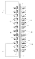
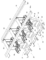
図1及び図2に示すように、物品搬送設備は、複数の物品処理部1を経由する状態で案内レール2(移動経路に相当する)が設置され、この案内レール2に沿って移動自在な移動車3(物品搬送体に相当する)が設けられている。移動車3が、半導体基板を収納した容器5(物品に相当する)を複数の物品処理部1の間で搬送するように構成されている。物品処理部1では、半導体基板の製造途中での半製品等に対して所定の処理を行うように構成されている。
An embodiment of an article conveying facility according to the present invention will be described based on the drawings.
This article conveyance facility is provided, for example, in a clean room provided with a downflow type purified air ventilation means for allowing purified air to flow downward from the ceiling side.
As shown in FIGS. 1 and 2, the article transport facility is provided with a guide rail 2 (corresponding to a movement path) in a state of passing through a plurality of article processing units 1, and is movable along the
移動車3は、容器5を吊り下げ状態で把持する把持部4を昇降自在に備えている。把持部4は、移動車3が停止した状態において、ワイヤ6を巻き取り又は巻き出すことにより、移動車3に近接位置させる上昇位置と移動車3よりも下方側に設置された物品移載用のステーション7との間で物品移載を行う下降位置とに昇降自在に設けられている。ちなみに、図2では、把持部4が上昇位置から下降位置に下降する場合を上方側に示し、把持部4を下降位置から上昇位置に上昇させる場合を下方側に示している。
The
ステーション7は、容器5を載置支持する床部に設けられた載置台にて構成されている。ステーション7は、物品処理部1にて所定の処理を行う容器5を移動車3から受け取る又は物品処理部1にて所定の処理を行った容器5を移動車3に受け渡すためのものであり、複数の物品処理部1の夫々に対応して配置されている。
移動車3は、把持部4を上昇位置に位置させた状態で案内レール2に沿って移動し、複数のステーション7のうち、移載対象のステーション7に対応する停止位置に停止した状態で把持部4を上昇位置と下降位置との間で昇降させることにより、ステーション7との間で容器5の授受を行うように構成されている。
The
The moving
案内レール2は、図2〜図4に示すように、案内レール用ブラケット8により天井部に固定状態で設置されている。移動車3は、案内レール2の内方空間部に位置する上方車体9と案内レール2の下方に位置する下方車体12とを前後の連結扞10,11にて連結して構成されている。
As shown in FIGS. 2 to 4, the
上方車体9は、案内レール2の内方空間部に設けられるマグネット13に近接対向させる状態で一次コイル14を備えている。上方車体9は、マグネット13と一次コイル14とからなるリニアモータにより推進力を得るリニアモータ式であり、移動車3は、この推進力によって案内レール2に沿って移動するように構成されている。案内レール2の内方空間部には、上方車体9に備えた走行輪15に対する走行案内面16と、上方車体9に備えた振止輪17に対する振止案内面18とが形成されている。
案内レール2には給電線19が設けられ、上方車体9には受電コイル20が設けられ、交流電流の通電により給電線19に磁界を発生させ、この磁界により移動車3側での必要電力を受電コイル20に発生させて、無接触状態で給電を行うように構成されている。
The
The
この実施形態では、上方車体9を駆動させる方式として、リニアモータにより推進力を得て駆動させるリニアモータ式を例示しているが、例えば、走行輪15を回転駆動する電動モータを設け、この電動モータにて走行輪15を回転駆動させることにより上方車体9を駆動させる方式を用いることもできる。
In this embodiment, as a method of driving the
下方車体12は、移動車3の前後方向に延びる前後枠体21、前後枠体21の前端箇所及び後端箇所から下方側に延びる前後一対の縦枠体22から構成されている。下方車体12は、側面視において、下方側が開放されたコ字状に形成され、前後方向の中央部に把持部4を配置している。
The
把持部4は、上方車体9に対して昇降自在な昇降体23に設けられ、この昇降体23は、前後枠体21に設けられた昇降操作機構24によって昇降操作自在に支持されている。
昇降操作機構24は、ドラム駆動用モータ25により回動自在な回転ドラム26に4本のワイヤ6を巻き掛けて構成されている。そして、昇降操作機構24は、回転ドラム26を正逆回転させて4本のワイヤ6を同時に巻き取り及び巻き出しすることによって、昇降体23を略水平姿勢に維持しながら昇降操作するように構成されている。
The
The lifting / lowering
この実施形態では、回転ドラム26にワイヤ6を巻き掛けた例を示しているが、例えば、回転ドラム26にベルトを巻き掛けて昇降体23を昇降操作することもでき、ワイヤ6に限らず、ベルトを用いることもできる。
In this embodiment, an example in which the
把持部4には、容器5のフランジ5aを把持する一対の把持具4aが設けられている。そして、一対の把持具4aが把持動作用モータ27の正逆回転により互いに近づく方向に揺動してフランジ5aを把持する把持姿勢(図3中実線)と、一対の把持具4aが互いに離れる方向に揺動して把持を解除する解除姿勢(図3中点線)とに切り換え自在に構成されている。把持部4は、縦軸芯周りで旋回自在に昇降体23に設けられ、図示は省略するが、把持部4を旋回操作する旋回用モータが設けられている。
The
ステーション7に搬送する容器5を一時的に保管するために、案内レール2の側脇には、図1及び図5に示すように、案内レール2に対して左右両側に物品保管用の物品支持体28が設けられている。そして、物品支持体28は、案内レール2に沿って隣接して並ぶ状態で複数設けられている。
In order to temporarily store the
以下、図5〜図10に基づいて、物品支持体28について説明する。
複数の物品支持体28の夫々は、それに対する物品移載箇所に停止した移動車3の把持部4からの容器5の受け取り及び把持部4への容器5の受け渡しを行う案内レール2に接近する側に突出する物品授受用の突出位置(図10参照)と案内レール2から離間する側に引退する引退位置(図9参照)とに位置変更自在に設けられている。
以下、物品移載箇所に停止した移動車3の前後方向、すなわち案内レール2に沿う方向を「前後方向」と略称し、且つ、物品移載箇所に停止した移動車3に対する遠近方向を「遠近方向」と略称して説明する。
Hereinafter, the
Each of the plurality of article supports 28 approaches the
Hereinafter, the front-rear direction of the moving
物品移載箇所は、複数の物品支持体28の夫々に対応して定められている。前後方向において物品支持体28の幅は移動車3における前後一対の縦枠体22の間隔よりも小さくなるように形成されている。したがって、物品移載箇所に移動車3が停止した状態において、移動車3における前後一対の縦枠体22の間に物品支持体28を挿脱できるように構成されている。
The article transfer location is determined corresponding to each of the plurality of article supports 28. In the front-rear direction, the width of the
引退位置は、物品支持体28が引退位置に位置するときに、自己及び自己が載置支持する容器5が移動車3の移動や把持部4の昇降の邪魔にならないように、案内レール2の存在箇所から遠近方向に外れた案内レール2の側脇に定められている。
突出位置は、物品支持体28が突出位置に位置するときに、物品移載箇所に停止した移動車3において上昇位置に近接する位置に位置する把持部4との間で容器5を授受できるように、物品移載箇所に停止した移動車3における把持部4と水平方向において重複する位置に定められている。
The retraction position is such that when the
The protruding position is such that when the
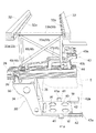
物品支持体28は、図5〜図8に示すように、引退位置に対応して天井側に設置された固定枠体29に対して突出位置と引退位置とに移動自在に支持されている。物品支持体28は、固定枠体29に対して遠近方向に移動自在に支持され且つ固定枠体29から下方に延びる形状に形成された移動体30と、移動体30の下端部から遠近方向の案内レール2に接近する側に延びるように設けられた載置体31とを備えている。
As shown in FIGS. 5 to 8, the
固定枠体29は、遠近方向に間隔を隔てた一対の固定枠体支持用の支持レール体32に亘る状態で吊り下げ支持されている。固定枠体29は、吊り下げ支持部33として、遠近方向の一方側及び他方側の夫々において固定枠体29から上方に延びる立壁部分33aと、立壁部分33aの上端部同士を連結する水平連結部分33bとを備えている。一対の支持レール体32の夫々には、水平連結部分33cにおいて遠近方向の一端部及び他端部の夫々を受け止め支持する受け止め支持部32aが設けられている。固定枠体29は、一対の支持レール体32の夫々における受け止め支持部32aにて受け止め支持された状態で固定することにより、一対の支持レール体32に吊り下げ支持されるように構成されている。
The fixed
固定枠体29を天井側に吊り下げ支持する構成は、上述の構成に限らず、適宜変更が可能である。例えば、固定枠体29の上端部にボルト取り付け用溝部を設け、このボルト取り付け用溝部に吊り下げ支持体の下端部をボルト固定し、吊り下げ支持体の上端部を天井部にボルト固定することにより、固定枠体29を天井側に吊り下げ支持することができる。
The configuration in which the fixed
移動体30は、上方よりも下方の方が遠近方向での幅が幅狭となる状態で下方に延びる形状に形成された左右一対の支持アーム体34と、左右一対の支持アーム体34の上端部同士を連結する上部連結体35と、左右一対の支持アーム体34の上端部から下方に延びる部分同士を連結する中間連結体36とから構成されている。支持アーム体34及び中間連結体36には、複数の孔部が形成されており、軽量化が図られている。上部連結体35には、前後方向の中央部に上方に突出する突出部37が設けられ、前後方向の一端部に棒状の連係用被操作体39が立設する状態で設けられている。突出部37には、その側面部に水平軸心周りで回転自在に支持された左右一対の第1ガイドローラ38aが遠近方向に間隔を隔てて2組設けられ、且つ、その上面部に上下軸心周りで回転自在に支持された左右一対の第2ガイドローラ38bが遠近方向に間隔を隔てて2組設けられている。
The
固定枠体29は、下方から移動体30の突出部37を内部に挿入させた状態で突出部37の遠近方向での移動を許容するように下方を開放させた筒状に形成されている。固定枠体29の下方は、前後方向の全長に亘って開放されているのではなく、その中央部のみ開放されており、両側の側壁部29aから水平方向に延びる底部29bが設けられている。固定枠体29の底部29bは、固定枠体29の内部に挿入された突出部37に支持された第1ガイドローラ38aを遠近方向に案内するように構成されている。固定枠体29の上部には、下方側に突出する案内レール部29cが遠近方向に沿って設けられている。この案内レール部29cは、固定枠体29の内部に挿入された突出部37に支持された第2ガイドローラ38bを遠近方向に案内するように構成されている。これにより、移動体30は、固定枠体29に対して遠近方向にスライド移動自在に支持されている。
The fixed
載置体31は、前後方向において容器5の幅内の幅狭で移動体30の下端部から遠近方向の案内レール2に接近する側に延びるように設けられた当接載置部40と、当接載置部40から前後方向に延びるように設けられて容器5の側面部に当接する立壁部分41aを備え且つ遠近方向において容器5よりも幅狭に形成された移動規制部41とから構成されている。移動規制部41は、当接載置部40において容器5の遠近方向の中央部に相当する箇所から前後方向の一端側及び他端側に延びるように一対設けられている。
The mounting
これにより、物品支持体28にて容器5を支持した状態において、前後方向で容器5の外側に突出する部分は、移動規制部41における立壁部分41aだけとなり、その立壁部分41aの両側から天井側から下方側への浄化空気の流れを許容できる。よって、物品支持体28が容器5を支持した状態において天井側から下方側への浄化空気の流れを阻害するのを防止することができ、塵埃の少ない清浄な環境において容器5を保管できる。このように、立壁部分41aの両側に下方側への浄化空気の流れを許容できるスペースを設けることにより、図1に示すように、前後方向において物品支持体28同士の間において下方側への浄化空気の流れを許容するスペースを極力小さくすることができる。これにより、前後方向で物品支持体28同士の間の間隔を小さくしながら、複数の物品支持体28を設けることができる。よって、前後方向に小さなスペースに複数の物品支持体28を効率よく設置することができる。
また、当接載置部40は、前後方向において容器5の中央部に設けられており、容器5の前後方向の中央部に当接して容器5を載置支持することができ、容器5を安定して支持することができる。しかも、移動規制部41における立壁部分41aが容器5の側面部に当接して、前後方向での容器5の移動を規制することができる。
As a result, in a state where the
The
当接載置部40は、遠近方向において容器5よりも幅狭に形成されており、遠近方向において案内レール2に接近する側に中空空間を形成するように構成されている。これにより、物品支持体38が容器5を支持していない状態においても、中空空間にて天井側から下方側への浄化空気の流れを許容でき、物品支持体28自体を塵埃の少ない清浄な環境としておくことができる。
The
当接載置部40には、当接載置部40から遠近方向に延びるように設けられて容器5の側面部に当接する立壁部分42aを備え且つ前後方向において当接載置部40よりも幅狭に形成された遠近方向移動規制部42が設けられている。遠近方向移動規制部42は、前後方向において当接載置部40の両端部に設けられている。これにより、遠近方向での容器5の移動を規制して容器5を載置支持することができる。当接載置部40には、容器5を位置決めした状態で載置するために複数の位置決めピンWが設けられている。位置決めピンWの配設箇所は、平面視において三角形の各角部となるように設けられている。当接載置部40には、複数の孔部が形成されており、物品支持体38が容器5を支持していない状態において下方側への浄化空気の流れを許容するとともに、軽量化が図られている。
The
移動体30と当接載置部40とは、遠近方向に連続する状態で設けられ、且つ、前後方向での幅が同じ又は略同じ幅となるように構成されている。固定枠体29は、前後方向において移動体30の中央部に設けられており、移動体30をバランスよく安定した状態で遠近方向に移動自在に支持することができる。固定枠体29は、引退位置の物品支持体28と前後方向及び遠近方向において重複するように配設され、且つ、前後方向において当接載置部40よりも幅狭に形成されている。これにより、水平方向において物品支持体28とは異なる箇所で、固定枠体29にて下方側への浄化空気の流れを阻害してしまうことがない。
The moving
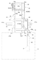
固定枠体29には、遠近方向において物品移載箇所に停止した移動車3に接近する接近位置(図9参照)と物品移載箇所に停止した移動車3から離間する離間位置(図10参照)とに移動自在に支持された被操作体43が設けられている。被操作体43は、接近位置では物品支持体28を引退位置に操作し、且つ、離間位置では物品支持体28を突出位置に操作するように、物品支持体28に連係されている。
The fixed
被操作体43は、その長手方向の中央部が固定枠体29の上部に設けられたコ字状の基体44に枢支連結されて、その連結箇所である第1揺動軸心P1周りに揺動自在に設けられている。被操作体43は、接近位置に位置する状態において、第1揺動軸心P1から移動車3に接近する側に延びる第1被操作部分43aと第1揺動軸心P1から移動車3から離れる側に延びる第2被操作部分43bとを上下に段差をつけて一体的に形成されている。
The operated
被操作体43は、第1揺動軸心P1周りでの揺動により接近位置と離間位置とに切換自在で且つ接近位置(図9参照)においては第1被操作部分43aが第1揺動軸心P1よりも物品移載箇所に停止した移動車3に接近する姿勢となるように設けられている。被操作体43の第1被操作部分43aには、被操作体43が接近位置に位置する状態において、遠近方向に対して交差する方向に沿って第1揺動軸心P1側に延びる溝部45が設けられている。この溝部45は、物品移載箇所に停止した移動車3に接近する側の先端を遠近方向に沿って開口させた形状に形成されている。
The operated
被操作体43が接近位置に位置すると、図9に示すように、物品支持体28を引退位置に位置させ、且つ、被操作体43が離間位置に位置すると、図10に示すように、物品支持体28を突出位置に位置させるように、被操作体43の動きと物品支持体28の動きとを連係させる連係機構46が設けられている。
When the operated
連係機構46は、上下軸心周りに揺動自在な第1リンクアーム47、第2リンクアーム48及び第3リンクアーム49の3つのリンクアームから構成されている。第1リンクアーム47は、一端部が被操作体43の第2操作部分43bの一端部に枢支連結され且つ他端部が第2リンクアーム48の長手方向の途中部分に枢支連結されている。第2リンクアーム48は、一端部が基体44に枢支連結され且つ他端部が第3リンクアーム49の一端部に枢支連結されている。第3リンクアーム49は、他端部が固定枠体29に立設された連係用被操作体39に枢支連結されている。
The
図9及び図10に示すように、移動車3には、物品支持体28を引退位置と突出位置とに変更操作するための操作手段50が設けられている。操作手段50は、移動車3に固定されて遠近方向に長尺状のベース51と、そのベース51に対して遠近方向に移動自在に設けられた長尺状の操作体52と、その操作体52の先端部の下面側に設けられた係合ローラ53とから構成されている。操作手段50は、図示を省略したアクチュエータの作動によりベース51に対して操作体52を出退させて、係合ローラ53を遠近方向に移動させる突出作動及び引退作動を行うように構成されている。ちなみに、移動車3には、移動車3の走行方向において右側に位置する物品支持体28を変更操作するための操作手段50と、移動車3の走行方向において左側に位置する物品支持体28を変更操作するための操作手段50とが設けられている。
As shown in FIGS. 9 and 10, the moving
係合ローラ53は、前後方向において被操作体43の溝部45の幅と同じ又はその幅よりも小さい直径に形成されている。これにより、係合ローラ53が、遠近方向での移動により被操作体43の溝部45に係脱自在に構成されている。操作手段50が、突出作動により係合ローラ53を溝部45に係合させて被操作体43を接近位置から離間位置に押し操作し、且つ、引退作動により係合ローラ53を溝部45に係合させて被操作体43を離間位置から接近位置に引き操作し、その後係合ローラ53を溝部45から離脱させる押し引き式に構成されている。
The
操作手段50が突出作動により係合ローラ53にて被操作体43を接近位置から離間位置に操作すると、被操作体43が離間位置に位置することにより物品支持体28を突出位置に操作して、物品支持体28を引退位置から突出位置に位置変更させる。逆に、操作手段50が引退作動により係合ローラ53にて被操作体43を離間位置から接近位置に操作すると、被操作体43が接近位置に位置することにより物品支持体28を引退位置に操作して、物品支持体28を突出位置から引退位置に位置変更させる。
When the operating means 50 is operated from the approach position to the separated position by the engaging
物品支持体28を引退位置と突出位置とに位置変更させるときの動きについて説明する。
図9に示すように、被操作体43が接近位置に位置すると、溝部45の開口部分が遠近方向に開口しているので、操作手段50が突出作動を行うことにより、係合ローラ53が遠近方向において移動車3から突出する側に移動して溝部45の開口から溝部45に嵌り込んで係合する。そして、係合ローラ53が溝部45に係合した状態で遠近方向において移動車3から突出する側に移動することにより、係合ローラ53が溝部45の側壁部を押圧しながら移動して被操作体43を接近位置から離間位置に押し操作する。被操作体43が接近位置から離間位置に揺動すると、第1リンクアーム47、第2リンクアーム48、及び、第3リンクアーム49が順次揺動して連係用被操作体39を移動車3に接近する側に移動させることになる。したがって、連係用被操作体39による移動車3に接近する側への移動によって移動体30をスライド移動させて、図10に示すように、物品支持体28が引退位置から突出位置に位置変更される。
The movement when changing the position of the
As shown in FIG. 9, when the object to be operated 43 is located at the approach position, the opening portion of the
図10に示すように、被操作体43が離間位置に位置するときに、操作手段50が引退作動を行うと、係合ローラ53が溝部45に係合した状態で移動車3に接近する側に移動することになり、係合ローラ53が溝部45の側壁部を押圧しながら移動して被操作体43を離間位置から接近位置に引き操作する。被操作体43が離間位置から接近位置に揺動すると、第1リンクアーム47、第2リンクアーム48、及び、第3リンクアーム49が順次揺動して連係用被操作体39を移動車3から離れる側に移動させることになる。したがって、連係用被操作体56による移動車3から離れる側への移動によって移動体30をスライド移動させて、物品支持体28が物品授受用位置から物品保管用位置に位置変更される。図9に示すように、被操作体43が接近位置に位置すると、溝部45の開口部分が遠近方向に開口しているので、係合ローラ53が移動車3に接近する側に移動することにより、係合ローラ53が溝部45を離脱して移動車3に引退する。
As shown in FIG. 10, when the operating means 50 performs the retraction operation when the operated
移動車3には、移動車3の動作を制御する台車用制御部が設けられている。そして、台車用制御部は、物品搬送設備全体の動作を管理する管理用コンピュータからの指令、及び、移動車3に設けられた各種センサの検出情報に基づいて、移動車3の移動及び把持部4の昇降作動を制御するとともに、把持動作用モータ27及び操作手段50の作動を制御するように構成されている。
The moving
例えば、管理用コンピュータから、複数のステーション7のうちから搬送元及び搬送先のステーション7を特定した状態で搬送元のステーション7から搬送先のステーション7に容器5を搬送する搬送指令が指令された場合には、台車用制御部が、搬送元のステーション7から容器5を受け取り、搬送先のステーション7に容器5を卸すべく、移動車3の動作を制御するように構成されている。
For example, a transfer command for transferring the
搬送元のステーション7から容器5を受け取る場合には、まず、台車用制御部は、搬送元のステーション7に対応する停止位置に移動車3を移動させるべく、移動車3の移動を制御する。次に、台車用制御部は、搬送元のステーション7に対応する停止位置に移動車3を停止させた状態で、上昇位置から下降位置に把持部4を下降させるべく、把持部4の昇降作動を制御する。そして、台車用制御部は、把持部4が下降位置に位置すると、把持動作用モータ27を作動させて一対の把持具4aを把持姿勢に切り換え、容器5のフランジ5aを一対の把持具4aにて把持して容器5を受け取る。その後、台車用制御部は、下降位置から上昇位置に把持部4を上昇させるべく、把持部4の昇降作動を制御したのち、搬送先のステーション7に対応する停止位置に移動車3を移動させるべく、移動車3の移動を制御する。
台車用制御部は、搬送先のステーション7に対応する停止位置に移動車3が停止すると、搬送元のステーション7から容器5を受け取る場合と同様に、把持部4の昇降作動や把持動作用モータ27の作動を制御することにより、搬送先のステーション7に容器5を卸すように構成されている。
When the
When the moving
また、管理用コンピュータから、複数の物品支持体28のうち移載対象の物品支持体28が特定された状態で物品支持体28に容器5を保管する保管指令が指令された場合について説明する。
台車用制御部が、まず、移載対象の物品支持体28に対応する物品移載箇所に移動車3を移動させるべく、移動車3の移動を制御する。次に、台車用制御部は、移載対象の物品支持体28に対応する物品移載箇所に移動車3を停止させた状態で、操作手段50を突出作動させる。操作手段50が突出作動を行うことにより、物品支持体28を引退位置から突出位置に位置変更させる。台車用制御部は、上昇位置からそれに近接する位置に把持部4を下降させるべく、把持部4の昇降作動を制御したのち、把持動作用モータ27を作動させて一対の把持具4aを解除姿勢に切り換え、把持部4から物品授受用位置に位置する物品支持体28に容器5を卸す。その後、台車用制御部は、把持部4を上昇位置まで上昇させるべく、把持部4の昇降作動を制御したのち、操作手段50を引退作動させる。そして、操作手段50が引退作動を行うことにより、物品支持体28を突出位置から引退位置に位置変更させる。
Further, a case will be described in which a storage command for storing the
The cart controller first controls the movement of the moving
管理用コンピュータから、複数の物品支持体28のうち移載対象の物品支持体28が特定された状態で物品支持体28にて保管している容器5を取り出す取出指令が指令された場合について説明する。
台車用制御部は、保管指令が指令された場合と同様に、移動車3の移動を制御することにより、移載対象の物品支持体28に対応する物品移載箇所に移動車3を停止させる。そして、台車用制御部は、操作手段50を突出作動させることにより、物品支持体28を物品保管用位置から物品授受用位置に位置変更させる。その後、台車用制御部は、上昇位置からそれに近接する位置へ把持部4を下降させるべく、把持部4の昇降作動を制御したのち、把持動作用モータ27を作動させて一対の把持具4aを把持姿勢に切り換え、物品支持体28から把持部4に容器5を受け取る。そして、台車用制御部は、上昇位置まで把持部4を上昇させるべく、把持部4の昇降作動を制御したのち、操作手段50を引退作動させる。操作手段50が引退作動を行うことにより、物品支持体28を突出位置から引退位置に位置変更させる。
Description will be given of a case where an instruction to take out a
Similarly to the case where the storage command is instructed, the cart controller controls the movement of the
〔別実施形態〕
(1)上記実施形態では、物品支持体28が、突出位置において、上昇位置に近接する位置に位置する把持部4との間で容器5を授受するように設けられているが、例えば、突出位置において、上昇位置に位置する把持部4との間で容器5を授受するように物品支持体29を設けることもできる。
また、突出位置において、物品支持体28が把持部4との間で容器5を授受する位置については、上昇位置に近接する位置または上昇位置に限らず、上昇位置よりも設定高さだけ下降した位置であってもよい。この場合には、物品支持体28を突出位置に位置させた状態で、把持部4を上昇位置から設定高さだけ下降させることにより、物品支持体28と把持部4との間での容器5の授受を行うことができることになる。
[Another embodiment]
(1) In the above embodiment, the
In addition, the position at which the
(2)上記実施形態では、物品支持体28を案内レール2に沿って並ぶ状態で複数設けているが、物品支持体28を設置する数については適宜変更が可能である。また、物品支持体28の設置位置についても、案内レール2に対して左右両側に設けているが、案内レール2の片側のみに設置することも可能である。
(2) In the above embodiment, a plurality of article supports 28 are provided in a state of being aligned along the
(3)上記実施形態では、移動車3に、移動車3の走行方向において右側に位置する物品支持体28を変更操作するための操作手段50と、移動車3の走行方向において左側に位置する物品支持体28を変更操作するための操作手段50との2つの操作手段50を設けているが、例えば、操作手段50が、移動車3の走行方向に対して右側及び左側の両側に係合ローラを出退自在に備えることにより、移動車3に1つの操作手段を設けて実施することもできる。
(3) In the above embodiment, the moving
(4)上記実施形態では、物品として、半導体基板を収納した容器5を搬送する物品搬送設備を例示したが、搬送する物品は適宜変更が可能である。
(4) In the above embodiment, the article transport facility for transporting the
2 移動経路(案内レール)
3 物品搬送体(移動車)
28 物品支持体
29 固定枠体
30 移動体
31 載置体
32 支持レール体
32a 受け止め支持部
40 当接載置部
41 移動規制部
41a 立壁部分
42 遠近方向移動規制部
42a 立壁部分
2 Movement route (guide rail)
3 article carrier (mobile)
28
Claims (6)
前記物品支持体は、天井側に設置された固定枠体に対して前記移動経路に接近する側に突出する物品授受用の突出位置と前記移動経路から離間する側に引退する引退位置とに移動自在に支持され、
前記物品搬送体は、前記物品移載箇所に停止した状態において、前記突出位置の前記物品支持体に対して物品の受け渡し及び受け取りを行うように構成されている物品搬送設備であって、
前記物品支持体は、前記固定枠体に対して前記移動経路に対する遠近方向に移動自在に支持され且つ前記固定枠体から下方に延びる形状に形成された移動体と、前記移動体の下端部から前記遠近方向に沿って延びるように設けられた載置体とを備え、
前記載置体は、前記移動経路に沿う方向において物品の幅内の幅狭で前記移動体の下端部から前記遠近方向に沿って延びるように設けられた当接載置部と、前記当接載置部から前記移動経路に沿う方向に延びるように設けられて物品の側面部に当接する立壁部分を備え且つ前記移動経路に対する遠近方向において物品よりも幅狭に形成された移動規制部とから構成されている物品搬送設備。 An article transporter is provided that is movable along a movement path on the ceiling side through an article transfer location with respect to the article support,
The article support moves to a protruding position for receiving and receiving articles that protrudes toward the side approaching the movement path with respect to a fixed frame installed on the ceiling side, and a retreat position that retreats away from the movement path. Freely supported,
The article transporter is an article transport facility configured to deliver and receive an article to and from the article support at the protruding position in a state where the article transporter is stopped at the article transfer location,
The article support body is supported by the fixed frame body so as to be movable in a perspective direction with respect to the movement path and extends downward from the fixed frame body, and a lower end portion of the movable body. A mounting body provided to extend along the perspective direction;
The mounting body includes a contact mounting portion provided so as to be narrow in the width of the article in the direction along the moving path and to extend from the lower end portion of the moving body along the perspective direction; A movement restricting portion that is provided so as to extend in a direction along the movement path from the placement section and includes a standing wall portion that comes into contact with a side surface portion of the article, and is formed narrower than the article in a perspective direction with respect to the movement path. Constructed goods transport equipment.
前記当接載置部から前記遠近方向に延びるように設けられて物品の側面部に当接する立壁部分を備え且つ前記移動経路に沿う方向において前記当接載置部よりも幅狭に形成された遠近方向移動規制部が設けられている請求項1又は2に記載の物品搬送設備。 The abutment mounting portion is formed narrower than the article in a perspective direction with respect to the movement path,
Provided so as to extend in the perspective direction from the abutment placement portion, and provided with a standing wall portion that abuts on the side surface portion of the article, and formed narrower than the abutment placement portion in the direction along the movement path. The article conveyance facility according to claim 1, wherein a perspective direction movement restriction unit is provided.
前記固定枠体は、前記一対の支持レール体の夫々における受け止め支持部にて受け止め支持された状態で前記一対の支持レール体に吊り下げ支持されている請求項1〜5の何れか1項に記載の物品搬送設備。 A pair of fixed frame support rails that are spaced apart in the perspective direction are provided on the ceiling side along the movement path,
6. The fixed frame body according to any one of claims 1 to 5, wherein the fixed frame body is suspended and supported by the pair of support rail bodies in a state in which the fixed frame body is received and supported by a receiving support portion in each of the pair of support rail bodies. The article conveying facility as described.
Priority Applications (7)
| Application Number | Priority Date | Filing Date | Title |
|---|---|---|---|
| JP2008101709A JP5062485B2 (en) | 2008-04-09 | 2008-04-09 | Goods transport equipment |
| US12/933,944 US9011068B2 (en) | 2008-04-09 | 2009-01-15 | Article transport facility |
| CN2009801217198A CN102067299B (en) | 2008-04-09 | 2009-01-15 | Article transportation facility |
| PCT/JP2009/050471 WO2009125615A1 (en) | 2008-04-09 | 2009-01-15 | Article transportation facility |
| EP09730037A EP2264750A4 (en) | 2008-04-09 | 2009-01-15 | Article transportation facility |
| KR20107022753A KR101389783B1 (en) | 2008-04-09 | 2009-01-15 | Article transportation facility |
| TW98101890A TWI438127B (en) | 2008-04-09 | 2009-01-19 | Article transport facility |
Applications Claiming Priority (1)
| Application Number | Priority Date | Filing Date | Title |
|---|---|---|---|
| JP2008101709A JP5062485B2 (en) | 2008-04-09 | 2008-04-09 | Goods transport equipment |
Publications (2)
| Publication Number | Publication Date |
|---|---|
| JP2009253162A true JP2009253162A (en) | 2009-10-29 |
| JP5062485B2 JP5062485B2 (en) | 2012-10-31 |
Family
ID=41161751
Family Applications (1)
| Application Number | Title | Priority Date | Filing Date |
|---|---|---|---|
| JP2008101709A Expired - Fee Related JP5062485B2 (en) | 2008-04-09 | 2008-04-09 | Goods transport equipment |
Country Status (7)
| Country | Link |
|---|---|
| US (1) | US9011068B2 (en) |
| EP (1) | EP2264750A4 (en) |
| JP (1) | JP5062485B2 (en) |
| KR (1) | KR101389783B1 (en) |
| CN (1) | CN102067299B (en) |
| TW (1) | TWI438127B (en) |
| WO (1) | WO2009125615A1 (en) |
Cited By (2)
| Publication number | Priority date | Publication date | Assignee | Title |
|---|---|---|---|---|
| JP2012044033A (en) * | 2010-08-20 | 2012-03-01 | Daifuku Co Ltd | Component storage facility |
| CN104444190A (en) * | 2014-09-28 | 2015-03-25 | 安徽康佳电子有限公司 | Automatic lifting device with liftable support |
Families Citing this family (10)
| Publication number | Priority date | Publication date | Assignee | Title |
|---|---|---|---|---|
| JP5590420B2 (en) * | 2011-12-21 | 2014-09-17 | 株式会社ダイフク | Goods transport equipment |
| KR101418812B1 (en) * | 2012-10-31 | 2014-07-16 | 크린팩토메이션 주식회사 | Apparatus for stocking and purging wafer at ceiling |
| KR101501257B1 (en) * | 2013-09-30 | 2015-03-11 | 크린팩토메이션 주식회사 | Mobile wafer stocking apparatus having purging function and wafer stocking system of purging type |
| JP6327124B2 (en) * | 2014-11-12 | 2018-05-23 | 株式会社ダイフク | Goods transport vehicle |
| EP3034414B1 (en) * | 2014-12-19 | 2017-02-22 | UHLMANN PAC-SYSTEME GmbH & Co. KG | Method for transferring articles to be packaged to containers and further transport of the filled containers |
| EP3034415B1 (en) * | 2014-12-19 | 2017-03-22 | UHLMANN PAC-SYSTEME GmbH & Co. KG | Method for transferring articles to be packaged to containers and further transport of the filled containers |
| US11876009B2 (en) * | 2018-11-06 | 2024-01-16 | Murata Machinery, Ltd. | Overhead transport vehicle |
| US11295973B2 (en) * | 2020-02-11 | 2022-04-05 | Taiwan Semiconductor Manufacturing Company, Ltd. | Apparatus and method for automated wafer carrier handling |
| CN113830469B (en) * | 2020-06-24 | 2022-05-17 | 长鑫存储技术有限公司 | Movable storage device, material conveying system and corresponding overhead traveling crane |
| KR20230023301A (en) * | 2021-08-10 | 2023-02-17 | 삼성전자주식회사 | Storage system including shelf moving module |
Citations (5)
| Publication number | Priority date | Publication date | Assignee | Title |
|---|---|---|---|---|
| JPH0936196A (en) * | 1995-07-17 | 1997-02-07 | Mitsubishi Electric Corp | Product feeding mechanism in clean room |
| JPH1045213A (en) * | 1996-08-06 | 1998-02-17 | Daifuku Co Ltd | Article carrying device |
| JP2003072917A (en) * | 2001-08-31 | 2003-03-12 | Daifuku Co Ltd | Baggage storing facility |
| JP2003072912A (en) * | 2001-08-31 | 2003-03-12 | Daifuku Co Ltd | Baggage storage facility |
| JP2007091463A (en) * | 2005-08-30 | 2007-04-12 | Daifuku Co Ltd | Article conveyance facility |
Family Cites Families (21)
| Publication number | Priority date | Publication date | Assignee | Title |
|---|---|---|---|---|
| EP0235488B1 (en) | 1986-09-19 | 1990-01-24 | REDOUTE CATALOGUE Société Anonyme: | Robotic handling system |
| US4762353A (en) * | 1987-03-09 | 1988-08-09 | Dexon, Inc. | Flexible carrier for semiconductor wafer cassettes |
| DE3714638A1 (en) | 1987-05-02 | 1988-12-01 | Megamat Gmbh & Co | Unloading and, if required, loading device |
| US4971508A (en) | 1987-06-29 | 1990-11-20 | Tsubakimoto Chain Co. | Storage and conveyance of heavy articles |
| TW348162B (en) * | 1996-09-30 | 1998-12-21 | Murada Kikai Kk | Work carrying system |
| US5927472A (en) * | 1997-10-15 | 1999-07-27 | Eisenmann Corporation | Conveyor transfer unit |
| US6435330B1 (en) * | 1998-12-18 | 2002-08-20 | Asyai Technologies, Inc. | In/out load port transfer mechanism |
| US20020025244A1 (en) * | 2000-04-12 | 2002-02-28 | Kim Ki-Sang | Transfer system and apparatus for workpiece containers and method of transferring the workpiece containers using the same |
| JP3829633B2 (en) * | 2001-02-22 | 2006-10-04 | 株式会社ダイフク | Load storage equipment |
| JPWO2003017344A1 (en) * | 2001-08-20 | 2004-12-09 | 株式会社ニコン | Mask replacement method and exposure apparatus |
| US6726429B2 (en) * | 2002-02-19 | 2004-04-27 | Vertical Solutions, Inc. | Local store for a wafer processing station |
| US7810645B2 (en) * | 2002-07-03 | 2010-10-12 | Taiwan Semiconductor Manufacturing Co., Ltd. | Paddle for securely mounting a wafer cassette holder thereto |
| JP4045451B2 (en) * | 2003-12-26 | 2008-02-13 | 村田機械株式会社 | Overhead traveling vehicle system |
| US7409263B2 (en) * | 2004-07-14 | 2008-08-05 | Applied Materials, Inc. | Methods and apparatus for repositioning support for a substrate carrier |
| JP2006051886A (en) * | 2004-08-12 | 2006-02-23 | Murata Mach Ltd | Ceiling traveling vehicle system |
| JP4337683B2 (en) * | 2004-08-16 | 2009-09-30 | 村田機械株式会社 | Transport system |
| JP4915051B2 (en) * | 2005-03-28 | 2012-04-11 | ムラテックオートメーション株式会社 | Automatic transfer system |
| DE102006039697B4 (en) * | 2006-08-21 | 2010-07-29 | SSI Schäfer Noell GmbH Lager- und Systemtechnik | Device and method for unloading trays loaded with pallet layers |
| JP5088468B2 (en) * | 2007-03-09 | 2012-12-05 | 村田機械株式会社 | Conveying system using a suspended conveying cart |
| JP4543338B2 (en) * | 2007-11-13 | 2010-09-15 | 村田機械株式会社 | Overhead vehicle system and its buffer construction method |
| US7984543B2 (en) * | 2008-01-25 | 2011-07-26 | Applied Materials, Inc. | Methods for moving a substrate carrier |
-
2008
- 2008-04-09 JP JP2008101709A patent/JP5062485B2/en not_active Expired - Fee Related
-
2009
- 2009-01-15 EP EP09730037A patent/EP2264750A4/en not_active Withdrawn
- 2009-01-15 US US12/933,944 patent/US9011068B2/en active Active
- 2009-01-15 KR KR20107022753A patent/KR101389783B1/en active IP Right Grant
- 2009-01-15 CN CN2009801217198A patent/CN102067299B/en active Active
- 2009-01-15 WO PCT/JP2009/050471 patent/WO2009125615A1/en active Application Filing
- 2009-01-19 TW TW98101890A patent/TWI438127B/en active
Patent Citations (5)
| Publication number | Priority date | Publication date | Assignee | Title |
|---|---|---|---|---|
| JPH0936196A (en) * | 1995-07-17 | 1997-02-07 | Mitsubishi Electric Corp | Product feeding mechanism in clean room |
| JPH1045213A (en) * | 1996-08-06 | 1998-02-17 | Daifuku Co Ltd | Article carrying device |
| JP2003072917A (en) * | 2001-08-31 | 2003-03-12 | Daifuku Co Ltd | Baggage storing facility |
| JP2003072912A (en) * | 2001-08-31 | 2003-03-12 | Daifuku Co Ltd | Baggage storage facility |
| JP2007091463A (en) * | 2005-08-30 | 2007-04-12 | Daifuku Co Ltd | Article conveyance facility |
Cited By (6)
| Publication number | Priority date | Publication date | Assignee | Title |
|---|---|---|---|---|
| JP2012044033A (en) * | 2010-08-20 | 2012-03-01 | Daifuku Co Ltd | Component storage facility |
| CN102376529A (en) * | 2010-08-20 | 2012-03-14 | 株式会社大福 | Container storage facility |
| US8926251B2 (en) | 2010-08-20 | 2015-01-06 | Daifuku Co., Ltd. | Container storage facility |
| CN102376529B (en) * | 2010-08-20 | 2015-06-17 | 株式会社大福 | Container storage facility |
| TWI496235B (en) * | 2010-08-20 | 2015-08-11 | Daifuku Kk | Container storage facility |
| CN104444190A (en) * | 2014-09-28 | 2015-03-25 | 安徽康佳电子有限公司 | Automatic lifting device with liftable support |
Also Published As
| Publication number | Publication date |
|---|---|
| KR101389783B1 (en) | 2014-04-30 |
| JP5062485B2 (en) | 2012-10-31 |
| TW200942469A (en) | 2009-10-16 |
| US20110056900A1 (en) | 2011-03-10 |
| CN102067299A (en) | 2011-05-18 |
| EP2264750A4 (en) | 2012-07-25 |
| US9011068B2 (en) | 2015-04-21 |
| TWI438127B (en) | 2014-05-21 |
| EP2264750A1 (en) | 2010-12-22 |
| CN102067299B (en) | 2013-09-04 |
| WO2009125615A1 (en) | 2009-10-15 |
| KR20100134028A (en) | 2010-12-22 |
Similar Documents
| Publication | Publication Date | Title |
|---|---|---|
| JP5062485B2 (en) | Goods transport equipment | |
| JP4378656B2 (en) | Goods transport equipment | |
| JP4632091B2 (en) | Goods transport equipment | |
| JP5041207B2 (en) | Goods transport equipment | |
| JP4378655B2 (en) | Article processing equipment | |
| JP4849331B2 (en) | Goods transport equipment | |
| JP5674041B2 (en) | Goods transport equipment | |
| JP5472209B2 (en) | Goods transport equipment | |
| JP4389181B2 (en) | Article processing equipment | |
| JP5429570B2 (en) | Goods transport equipment | |
| JP2008195471A (en) | Article conveying facility | |
| JP5527619B2 (en) | Ceiling-mounted goods transport equipment | |
| JP5316907B2 (en) | Goods transport equipment | |
| JP2012044033A (en) | Component storage facility | |
| KR20200050973A (en) | Transport vehicle, and transport equipment | |
| TWI722208B (en) | Transport system | |
| JP2009029568A (en) | Article storage facility | |
| IL271508A (en) | Transport system and transport method | |
| JP2012144334A (en) | Article carrying device | |
| JP4626812B2 (en) | Goods transport equipment | |
| JP2003300617A (en) | Moving equipment and shelf equipment using the same |
Legal Events
| Date | Code | Title | Description |
|---|---|---|---|
| A621 | Written request for application examination |
Free format text: JAPANESE INTERMEDIATE CODE: A621 Effective date: 20091217 |
|
| A131 | Notification of reasons for refusal |
Free format text: JAPANESE INTERMEDIATE CODE: A131 Effective date: 20111102 |
|
| A521 | Request for written amendment filed |
Free format text: JAPANESE INTERMEDIATE CODE: A523 Effective date: 20111227 |
|
| A131 | Notification of reasons for refusal |
Free format text: JAPANESE INTERMEDIATE CODE: A131 Effective date: 20120426 |
|
| A521 | Request for written amendment filed |
Free format text: JAPANESE INTERMEDIATE CODE: A523 Effective date: 20120607 |
|
| TRDD | Decision of grant or rejection written | ||
| A01 | Written decision to grant a patent or to grant a registration (utility model) |
Free format text: JAPANESE INTERMEDIATE CODE: A01 Effective date: 20120712 |
|
| A01 | Written decision to grant a patent or to grant a registration (utility model) |
Free format text: JAPANESE INTERMEDIATE CODE: A01 |
|
| A61 | First payment of annual fees (during grant procedure) |
Free format text: JAPANESE INTERMEDIATE CODE: A61 Effective date: 20120725 |
|
| R150 | Certificate of patent or registration of utility model |
Ref document number: 5062485 Country of ref document: JP Free format text: JAPANESE INTERMEDIATE CODE: R150 Free format text: JAPANESE INTERMEDIATE CODE: R150 |
|
| FPAY | Renewal fee payment (event date is renewal date of database) |
Free format text: PAYMENT UNTIL: 20150817 Year of fee payment: 3 |
|
| R250 | Receipt of annual fees |
Free format text: JAPANESE INTERMEDIATE CODE: R250 |
|
| R250 | Receipt of annual fees |
Free format text: JAPANESE INTERMEDIATE CODE: R250 |
|
| R250 | Receipt of annual fees |
Free format text: JAPANESE INTERMEDIATE CODE: R250 |
|
| R250 | Receipt of annual fees |
Free format text: JAPANESE INTERMEDIATE CODE: R250 |
|
| R250 | Receipt of annual fees |
Free format text: JAPANESE INTERMEDIATE CODE: R250 |
|
| R250 | Receipt of annual fees |
Free format text: JAPANESE INTERMEDIATE CODE: R250 |
|
| R250 | Receipt of annual fees |
Free format text: JAPANESE INTERMEDIATE CODE: R250 |
|
| LAPS | Cancellation because of no payment of annual fees |