JP2009247677A - Endoscope system - Google Patents
Endoscope system Download PDFInfo
- Publication number
- JP2009247677A JP2009247677A JP2008100375A JP2008100375A JP2009247677A JP 2009247677 A JP2009247677 A JP 2009247677A JP 2008100375 A JP2008100375 A JP 2008100375A JP 2008100375 A JP2008100375 A JP 2008100375A JP 2009247677 A JP2009247677 A JP 2009247677A
- Authority
- JP
- Japan
- Prior art keywords
- endoscope
- specifications
- processor device
- endoscope system
- electronic endoscope
- Prior art date
- Legal status (The legal status is an assumption and is not a legal conclusion. Google has not performed a legal analysis and makes no representation as to the accuracy of the status listed.)
- Pending
Links
Images


Landscapes
- Instruments For Viewing The Inside Of Hollow Bodies (AREA)
- Endoscopes (AREA)
- Closed-Circuit Television Systems (AREA)
Abstract
Description
本発明は、内視鏡の仕様に応じた仕様を変更可能なプロセッサ装置を有する内視鏡システムに関する。 The present invention relates to an endoscope system having a processor device capable of changing specifications according to the specifications of an endoscope.
内視鏡及びプロセッサ装置からなる内視鏡システムは、内視鏡に設けられたCCDなどの撮像素子で被検体内を撮像した撮像信号をプロセッサ装置に取り込み、この撮像信号からプロセッサ装置で画像を形成し、さらに形成した画像にノイズ軽減やブレ補正、色補正や、ホワイトバランス補正などの画像処理を行って出力し、モニタに画像を表示させる。 An endoscope system including an endoscope and a processor device captures an imaging signal obtained by imaging the inside of a subject with an imaging device such as a CCD provided in the endoscope, and the processor device captures an image from the imaging signal. The formed image is subjected to image processing such as noise reduction, blur correction, color correction, white balance correction, and the like to be output, and the image is displayed on the monitor.
内視鏡は、世界の様々な国、地域などの仕向け地によって仕様が異なるため、プロセッサ装置の仕様も内視鏡の仕様に合わせて、表示メニューの言語や、モニタの表示方式、接続可能な周辺機器、画像処理の方法などを変える必要がある。 Endoscope specifications vary depending on the destination in various countries and regions of the world, so the specifications of the processor unit can be connected to the display menu language, monitor display method, etc. according to the endoscope specifications. Peripheral devices and image processing methods need to be changed.
従来は、内視鏡の様々な仕様に合わせるために、プロセッサ装置を共通のデバイスで構成し、このデバイスで処理するソフトを各仕様に合わせて変更していた。特許文献1記載の電子内視鏡装置(プロセッサ装置)は、プログラミング可能なデバイスによって構成され、操作者が特定機能のプログラミングをすることによって設定を変更していた。
しかしながら、内視鏡の仕様に合わせて、プロセッサ装置のソフトを変更したり、特許文献1のようにプログラミングを変えたりする場合、煩雑且つ面倒である。また、仕様に合わせてソフトを変更する場合、仕様の数が増加してくると、ソフトの変更ミスや、管理ミスで、実際の仕様とは別のものを入れてしまうなどの問題が起きる。さらに、モニタに表示される設定画面に、仕様によっては必要のない項目が表示されたりすると、誤って選択してしまって機能せず、故障などと判断される可能性もある。
However, when the software of the processor device is changed in accordance with the specifications of the endoscope or the programming is changed as in
本発明は上記事情を考慮してなされたものであり、内視鏡の仕様に合わせて、プロセッサ装置の仕様を容易に変更可能とし、変更後の仕様が認識可能な内視鏡システムを提供することを目的とする。 The present invention has been made in consideration of the above circumstances, and provides an endoscope system in which the specifications of a processor device can be easily changed in accordance with the specifications of the endoscope and the changed specifications can be recognized. For the purpose.
上記目的を達成するために、本発明の内視鏡システムは、撮像手段を備えた内視鏡と、前記内視鏡が接続され、前記撮像手段から得られる撮像信号を取り込んで画像処理を施す画像処理手段を備えたプロセッサ装置とからなる内視鏡システムにおいて、前記プロセッサ装置は、外部から選択操作可能、且つ選択状態を保持する複数の手動選択手段と、複数の仕様の中から、接続される前記内視鏡の仕様に応じた仕様を、前記手動選択手段の選択状態に応じて変更する仕様変更手段とを備えたことを特徴とする。 In order to achieve the above object, an endoscope system according to the present invention is connected to an endoscope provided with an imaging unit and the endoscope, and performs image processing by capturing an imaging signal obtained from the imaging unit. In an endoscope system comprising a processor device provided with an image processing means, the processor device is connected to a plurality of manual selection means capable of performing a selection operation from the outside and maintaining a selected state, from a plurality of specifications. And a specification changing unit that changes a specification according to the specification of the endoscope according to a selection state of the manual selection unit.
なお、前記仕様変更手段は、前記内視鏡に設けられた操作ボタンに関する仕様を切り替えることが好ましい。また、前記仕様変更手段は、言語仕様を切り替えることが好ましい。さらにまた、前記仕様変更手段は、カラー表示方式、接続可能な周辺機器の種類、日付の表示方法、接続される前記内視鏡のコネクタ種類の認識のいずれかに関する仕様を切り替えることが好ましい。 In addition, it is preferable that the said specification change means switches the specification regarding the operation button provided in the said endoscope. The specification changing means preferably switches language specifications. Furthermore, it is preferable that the specification changing unit switches specifications regarding any of a color display method, types of peripheral devices that can be connected, a date display method, and recognition of a connector type of the endoscope to be connected.
前記手動選択手段は、ディップスイッチからなることが好ましい。なお、前記仕様変更手段で変更された仕様に基づいた各種機能の設定画面をモニタに表示させる表示制御手段を備えたことが好ましい。また、前記表示制御手段は、前記仕様変更手段による仕様の変更に伴って無効となった機能を前記設定画面に非表示とすることが好ましい。 The manual selection means preferably comprises a dip switch. In addition, it is preferable to include display control means for displaying various function setting screens based on the specifications changed by the specification changing means on the monitor. Further, it is preferable that the display control unit hides the function that has become invalid due to the change of the specification by the specification changing unit on the setting screen.
本発明によれば、プロセッサ装置の外部から選択操作可能、且つ選択状態を保持する複数の手動選択手段の選択操作によって、複数の仕様の中から、接続される内視鏡の仕様に応じた仕様に変更可能とするので、内視鏡の仕様に合わせて、プロセッサ装置の仕様を容易に変更することが可能となり、変更後の仕様を認識することができる。 According to the present invention, the specification according to the specification of the endoscope to be connected is selected from the plurality of specifications by the selection operation of the plurality of manual selection means that can be selected from the outside of the processor device and holds the selection state. Therefore, the specification of the processor device can be easily changed according to the specification of the endoscope, and the changed specification can be recognized.
図1において、内視鏡システム2は、電子内視鏡10と、プロセッサ装置11と、光源装置12とから構成される。プロセッサ装置11の前面には、プロセッサ装置11の電源をオン/オフするための電源スイッチ13が設けられ、光源装置12の前面には、光源装置12の電源をオン/オフする電源スイッチ14、及び後述する光源51(図3参照)を点灯/消灯するための点灯スイッチ15が設けられている。
In FIG. 1, the
図2において、プロセッサ装置11の側面には、メンテナンス蓋16が開閉自在に取り付けられている(図1も参照)。このメンテナンス蓋16を開き位置にすると、プロセッサ装置11の内部に設けられた複数のディップスイッチSW1〜SW6(手動選択手段)が露呈する。これらのディップスイッチSW1〜SW6は、例えばスライドスイッチからなり、メンテナンス蓋16を開き位置にしたとき外部から専用工具などで、オン/オフの選択操作をすることが可能であり、且つ選択したオン/オフいずれかの状態を保持することができる。
2, a
図1にもどって、電子内視鏡10は、体腔内に挿入される可撓性の挿入部17と、挿入部17の基端部分に連設された操作部18と、プロセッサ装置11に接続される通信用コネクタ19と、光源装置12に接続される光源用コネクタ20と、操作部18とコネクタ19,20とを繋ぐユニバーサルコード21とを備えている。プロセッサ装置11は、電子内視鏡10及び光源装置12と電気的に接続しており、内視鏡システム2全体の動作を統括的に制御する。
Returning to FIG. 1, the
挿入部17の先端には、体腔内撮影用のCCD27(図3参照)などが内蔵された先端部17aが連設されている。先端部17aの後方には、複数の湾曲駒を連結した湾曲部17bが設けられている。湾曲部17bは、操作部18に設けられたアングルノブ22が操作されて、挿入部17内に挿設されたワイヤが押し引きされることにより、上下左右方向に湾曲動作する。これにより、先端部17aが体腔内の所望の方向に向けられる。
At the distal end of the
操作部18には、第1〜第3操作ボタン23a〜23cが設けられている。第1〜第3操作ボタン23a〜23cは、モニタ45に表示された画像を一時停止するフリーズ機能、フリーズ機能と静止画を記録する機能とを併せたトリガー機能、静止画を記録するレコード機能のいずれかを、後述する設定画面48a,48bによって割り当てることが可能である。なお、操作ボタン23a〜23cに割り当て可能な機能としては、上記の他に、絞り値の設定を切り替えるアイリスモード切替機能、電子拡大のオン/オフを切り替える電子拡大切替機能、患者氏名や検査日等の各種情報の表示/非表示を切り替える表示切替機能等があるが、本実施形態では、フリーズ機能、トリガー機能、レコード機能の三機能を代表として詳述する。
The
第1〜第3操作ボタン23a〜23cのうち、フリーズ機能が割り当てられたボタンを押圧操作すると、そのときCCD27で撮像して得られた画像データが画像メモリ(図示せず)にラッチされる。モニタ45(図1および図3参照)には、画像メモリにラッチされた画像データに基づいた画像(静止画)が親画面で表示され、リアルタイムの動画が子画面でPinP(Picture in Picture)表示される。この状態でフリーズ機能が割り当てられたボタンをもう一度押圧操作すると、モニタ45の表示は静止画表示が解除され、動画が全画面表示される通常の状態に復帰する。
When one of the first to
トリガー機能には、後述する設定画面48a,48bによってさらに、フリーズ/トリガーモードとフリーズ+トリガーモードの2種類のモード設定が可能となっている。トリガー機能が割り当てられたボタンを押圧操作すると、フリーズ/トリガーモードが設定されていた場合は、フリーズ機能の場合と同様に、モニタ45に静止画が表示される。そして、最初の押圧操作から所定時間内に、もう一度トリガー機能が割り当てられたボタンを押圧操作すると、そのときCCD27で撮像して得られた画像データがCFカード等の外部記録メディア(図示せず)に記録される。所定時間内に押圧操作がない場合は、自動的にモニタ45の表示が通常の状態に復帰する。
In the trigger function, two kinds of mode settings of a freeze / trigger mode and a freeze + trigger mode can be further set by setting
一方、フリーズ+トリガーモードが設定されていた場合は、トリガー機能が割り当てられたボタンを押圧操作すると、上記同様にモニタ45に静止画が表示される。最初の押圧操作から所定時間内に、もう一度トリガー機能が割り当てられたボタンを押圧操作すると、上記とは逆に、自動的にモニタ45の表示が通常の状態に復帰し、所定時間内に押圧操作がない場合は、これも上記とは逆に、画像データが記録される。
On the other hand, when the freeze + trigger mode is set, when a button to which a trigger function is assigned is pressed, a still image is displayed on the
レコード機能が割り当てられたボタンを押圧操作すると、そのときフリーズ操作がされている(モニタ45に静止画が表示されている)場合は、画像データが記録される。フリーズ操作がされていなかった(モニタ45に動画が全画面表示されていた)場合は、モニタ45に所定時間静止画が表示された後、自動的に画像データが記録される。
When a button to which a record function is assigned is pressed, image data is recorded if a freeze operation is performed at that time (a still image is displayed on the monitor 45). When the freeze operation has not been performed (a moving image is displayed on the
電子内視鏡10には、第1〜第3操作ボタン23a〜23cが全て備わっているものと、第1、第3操作ボタン23a、23cの二つしか備わっていないものがある。操作ボタンの配備に関する仕様は、電子内視鏡10の仕向け地によって異なる。本実施形態では、図1に示す前者の仕様の電子内視鏡10を米国、欧州向け、後者の仕様の電子内視鏡10を日本向けとする。また、米国、欧州向けには、通信用コネクタ19の仕様が異なる2種類の電子内視鏡10があり、日本向けには、通信用コネクタ19が共通の1種類の電子内視鏡10があるものとする。
Some
図3において、先端部17aには、観察窓24、照明窓25が設けられている。観察窓24の奥には、被検体内の像光を取り込むための光学系26が取り付けられ、さらに光学系26の奥には、CCD27が取り付けられている。CCD27は、例えばインターライントランスファ型のCCDを使用する。なお、撮像素子としては、CCD27に限らず、CMOSを用いてもよい。CCD27には、挿入部17、操作部18、ユニバーサルコード21の内部を通る信号ライン28,29が接続されている。信号ライン28は、ユニバーサルコード21及び通信用コネクタ19を介してプロセッサ装置11に接続される。
In FIG. 3, an
通信用コネクタ19の内部には、信号ライン29と接続された増幅器(以下、AMPと略す)30と、相関二重サンプリング/プログラマブルゲインアンプ(以下、CDS/PGAと略す)31と、A/D変換器(以下、A/Dと略す)32とが設けられている。AMP30は、CCD27から出力された撮像信号に所定のゲインで増幅を施し、これをCDS/PGA31に出力する。
The
CDS/PGA31は、AMP30で増幅された撮像信号に相関二重サンプリングを施してノイズ低減し、A/D32に出力する。A/D32は、CDS/PGA31から出力されたアナログの撮像信号を、デジタルの撮像信号に変換して出力する。A/D32から出力されたデジタルの撮像信号は、信号ライン33を介してプロセッサ装置11に送られる。
The CDS /
照明窓25の奥には、照射レンズ34が設けられる。この照射レンズ34には、ライトガイド35の出射端が面している。ライトガイド35は、挿入部17、操作部18、ユニバーサルコード21、及び光源用コネクタ20の内部を通っており、光源用コネクタ20の後方から入射端35aが露呈する。ライトガイド35は、多数の光ファイバ(例えば、石英からなる)を束ねて形成されたものである。
An
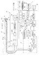
プロセッサ装置11には、タイミング/ドライバ回路36、画像形成回路37、画像処理回路38、表示回路39、RAM40、ROM41、入出力I/F42、固有情報読取部43、これらを制御するシステムコントローラ44、及びディップスイッチSW1〜SW6が設けられている。電子内視鏡10の通信用コネクタ19がプロセッサ装置11に接続されたとき、CCD27は信号ライン28を介してタイミング/ドライバ回路36に接続され、A/D32は信号ライン33を介して画像形成回路37にそれぞれ接続される。
The
固有情報読取部43は、プロセッサ装置11に接続された電子内視鏡10の固有情報を読み取り、システムコントローラ44へ出力する。システムコントローラ44は、取得した電子内視鏡10の固有情報から電子内視鏡の機種を認識し、電子内視鏡10の機種がプロセッサ装置11に対応か、未対応かに応じて電子内視鏡10の駆動制御を切り替える。固有情報読取部43としては、例えば、通信用コネクタ19がプロセッサ装置11に接続されたとき、通信用コネクタ19に設けられたRFIDタグから固有情報を読み取るタグリーダから構成される。なお、固有情報には、機種情報の他、プロセッサ装置11に電子内視鏡10を適合させるための色補正情報や、アイリス情報などが含まれている。
The unique
画像形成回路37は、デジタルの撮像信号から画像データを形成するための各種信号処理を行う。画像形成回路37が行う信号処理としては、RGB信号(撮像信号)を輝度信号及び色差信号に分離する色分離処理、分離された色差信号に対する擬色の除去処理、分離した輝度信号及び色差信号をマトリクス演算し、RGB信号からなる画像データを形成するマトリクス演算処理、CCD27の欠損画素を補間する画素補間処理、ゲイン補正、ホワイトバランス調整、ガンマ補正ななどを行う。画像形成回路37で形成された画像データは、画像処理回路38へ出力される。
The
画像処理回路38は、複数の論理回路から構成されており、画像データに複数種の画像処理を施す。画像処理回路38で施される画像処理としては、例えば、輪郭強調処理、あるいは特定の色や領域の強調処理、明度の調整処理などである。
The
画像処理回路38で画像処理が施された画像データは、表示回路39へ出力される。表示回路39は、画像処理から出力された画像データにマスキングを施して映像信号として出力し、プロセッサ装置11にケーブル接続されたモニタ45(図1も参照)に内視鏡画像として表示させる。
The image data that has been subjected to image processing by the
タイミング/ドライバ回路36は、CCD27の蓄積電荷の読み出しタイミング、CCD27の電子シャッタのシャッタ速度などを制御するための駆動パルス、また画像形成回路37や画像処理回路38での各種信号処理を行うための水平同期信号及び垂直同期信号を生成する。
The timing /
入出力I/F42は、マウス46aやキーボード46bなどの入力機器46や、プリンタやビデオレコーダなどの周辺機器47と接続し、これらとの間のデータの送受信を行う。
The input / output I /
ROM41には、内視鏡システム2を動作させるためのOS等の基本ソフトウェアや、ファームウェアなどが記憶されている。システムコントローラ44は、ROM41から作業用メモリであるRAM40に各種ソフトウェアのプログラムを読み出し、これらに基づいてプロセッサ装置11の各部を制御する。
The ROM 41 stores basic software such as an OS for operating the
ディップスイッチSW1〜SW6の選択状態は、プロセッサ装置11の電源投入時にファームウェアで読み取られる。システムコントローラ44は、読み取ったディップスイッチSW1〜SW6の選択状態に応じて、各部の動作を制御することで、プロセッサ装置11の各種仕様を変更する。
The selected state of the DIP switches SW1 to SW6 is read by firmware when the
以下の表1では、ディップスイッチSW1〜SW6のうち、ディップスイッチSW1〜SW5の選択操作で、電子内視鏡10の仕向け地に応じた仕様に変更したプロセッサ装置11の仕様について示す。
Table 1 below shows the specifications of the
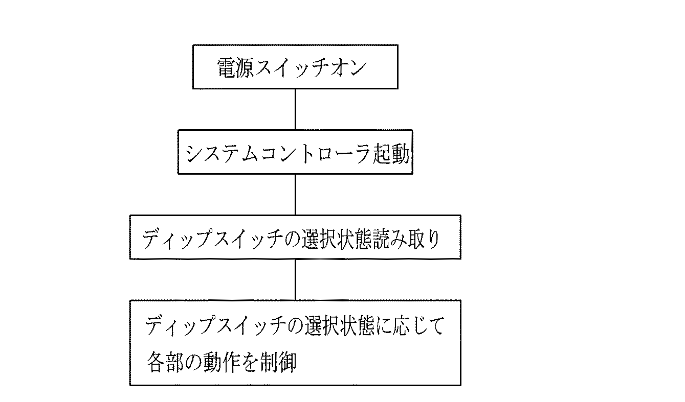
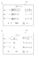
表1において、ディップスイッチSW1〜SW6で変更可能な仕様には、カラー表示方式、メッセージ言語、キーボード、コネクタの認識、日付表示、周辺機器(ビデオレコーダ)、操作ボタン配置がある。なお、周辺機器(プリンタ)については、タイプA〜Cで共通であるので、ディップスイッチに関わりなく、プリンタA、B、Cで固定である。 In Table 1, specifications that can be changed by the DIP switches SW1 to SW6 include color display method, message language, keyboard, connector recognition, date display, peripheral device (video recorder), and operation button arrangement. Since peripheral devices (printers) are common to the types A to C, they are fixed to the printers A, B, and C regardless of the dip switches.
カラー表示方式は、モニタ45への画像の表示出力規格を変更するもので、ディップスイッチSW2で変更可能である。ディップスイッチSW2をオンにすると、タイプCの欧州向けの表示規格であるPAL、ディップスイッチSW2をオフにすると、タイプA、Bの日本、米国向けの表示規格であるNTSCにそれぞれ変更される。
The color display method changes the display output standard of the image on the
メッセージ言語は、モニタ45に表示する各種文字情報の言語を変更するものである。また、キーボードは、キーボード46bによる操作入力言語を変更するものであり、日付表示は、モニタ45に表示する日付の並び順を変更するものである。さらに、周辺機器(ビデオレコーダ)は、周辺機器47のうち、接続可能なビデオレコーダを規定するものであり、操作ボタン配置は、電子内視鏡10の操作ボタン配置を規定するものである。これらの仕様は、ディップスイッチSW3で変更可能である。ディップスイッチSW3をオンにすると、メッセージ言語が日本語、キーボードが日本語キーボード、日付表示が年/月/日の順、操作ボタン配置が第1及び第3操作ボタン23a,23c、周辺機器(ビデオレコーダ)がビデオレコーダA、B、C、ディップスイッチSW3をオフにすると、メッセージ言語が英語、キーボードが英語キーボード、日付表示が月/日/年の順(ディップスイッチSW2がオフの場合)、あるいは日/月/年の順(ディップスイッチSW2がオンの場合)、操作ボタン配置が第1〜第3操作ボタン23a〜23c、周辺機器(ビデオレコーダ)が使用不可にそれぞれ変更される。
The message language changes the language of various character information displayed on the
未対応電子内視鏡の使用は、プロセッサ装置11に未対応の電子内視鏡10が接続された場合の仕様を変更するものである。この仕様は、ディップスイッチSW5で変更可能である。電子内視鏡10が対応か、未対応かの識別については、電子内視鏡10が通信用コネクタ19を介してプロセッサ装置11に接続されたとき、固有情報読取部43が、電子内視鏡10から読み出した固有情報に基づいてシステムコントローラ44が識別する。そして、電子内視鏡10が固有情報を格納していない場合、あるいは、読み出した固有情報にプロセッサ装置11に適合する情報が含まれて無かった場合、システムコントローラ44は、この電子内視鏡10がプロセッサ装置11に未対応の機種であることを認識する。
The use of an unsupported electronic endoscope changes the specifications when the unsupported
ディップスイッチSW5をオンにすると、システムコントローラ44は、NO(使用不可)、すなわち、プロセッサ装置11に接続された電子内視鏡10が未対応の機種であることが認識されたとき、電子内視鏡10への電力及び駆動信号の供給を行わず、さらに未対応の電子内視鏡10が接続されていることをモニタ45に表示する。一方、ディップスイッチSW5をオフにすると、システムコントローラ44は、YES(使用可能;NOと選択可)、すなわち、プロセッサ装置11に接続された電子内視鏡10が未対応の機種であることが認識された場合、プロセッサ装置11の初期設定のデータを用いて電子内視鏡10へ電力及び駆動信号を供給し、電子内視鏡10による撮像を可能にする。なお、プロセッサ装置11に接続された電子内視鏡10がプロセッサ装置11に対応する機種であることが認識されたときは、ディップスイッチSW5のオン/オフに関係無く、システムコントローラ44は、読み出した固有情報に基づいて電子内視鏡10へ電力及び駆動信号を供給し、電子内視鏡10による撮像を可能にする。
When the dip switch SW5 is turned on, the
なお、タイプA〜Cについては、タイプAは日本国内向け、タイプBは米国向け、タイプCは欧州向けの電子内視鏡10の仕様に合わせたプロセッサ装置11の仕様を示す。タイプAを選択するときには、ディップスイッチSW1,SW3,SW5をオン、ディップスイッチSW2,SW4をオフにする。同様にタイプBを選択するときには、ディップスイッチSW1をオン、ディップスイッチSW2〜5をオフに、タイプCを選択するときには、ディップスイッチSW1,SW2をオン、ディップスイッチSW3〜SW5をオフにする。
As for types A to C, type A indicates specifications of the
そして、タイプAが選択されたときは、カラー表示方式がNTSC、メッセージ言語が日本語、キーボードの仕様が日本語キーボード、コネクタの認識はNO、日付表示が年/月/日(年、月、日はそれぞれ数字が入る)で、周辺機器がプリンタA,B,C及びビデオレコーダA,B,Cに対応し、操作ボタン配置については第1及び第3操作ボタン23a,23cとなる。このタイプAの場合、電子内視鏡10には、上述の通り、通信用コネクタ19の種類が1通りしかないので、コネクタの認識を行う必要が無く、上述したように第2操作ボタン23bが省略されているため、この第2操作ボタン23bに関する表示メニューも設定画面48a,48bに表示されない(図4参照)。なお、日付表示は年/月/日がデフォルト状態の設定で、入力機器46によってデフォルト設定以外の日付表示に変更することができる(タイプB、及びタイプCについても同様)。
When Type A is selected, the color display method is NTSC, the message language is Japanese, the keyboard specification is Japanese keyboard, the connector recognition is NO, the date display is year / month / day (year, month, The number is entered for each day), and the peripheral devices correspond to the printers A, B, C and the video recorders A, B, C, and the operation button arrangement is the first and
また、タイプBが選択されたときは、カラー表示方式がNTSC、メッセージ言語が英語、キーボードの仕様が英語キーボード、コネクタの認識がYES、日付表示が月/日/年で、周辺機器がプリンタA,B,Cに対応し、ビデオレコーダは使用不可、操作ボタン配置については第1〜第3操作ボタン23a〜23cとなる。
When type B is selected, the color display method is NTSC, the message language is English, the keyboard specification is English keyboard, the connector recognition is YES, the date display is month / day / year, and the peripheral device is printer A. , B, and C, the video recorder cannot be used, and the operation button arrangement is the first to
また、タイプCが選択されたときは、カラー表示方式がPAL、メッセージ言語が英語、キーボードの仕様が英語キーボード、コネクタの認識がYES、日付表示が日/月/年で、周辺機器がプリンタA,B,Cに対応し、ビデオレコーダは使用不可、操作ボタン配置については第1〜第3操作ボタン23a〜23cとなる。
When type C is selected, the color display method is PAL, the message language is English, the keyboard specification is English keyboard, the connector recognition is YES, the date display is day / month / year, and the peripheral device is printer A. , B, and C, the video recorder cannot be used, and the operation button arrangement is the first to
なお、ディップスイッチSW1は、バックアップ用のROMの種別を選択するもので、ディップスイッチSW1をオンにすると、プロセッサ装置11内蔵のフラッシュメモリ(図示せず)から起動し、ディップスイッチSW1をオフにすると、プロセッサ装置11の回路基板に接続可能な外部のEEPROM(図示せず)から起動する方式に変更される。なお、このディップスイッチSW1は、通常はオンが選択される。ディップスイッチSW4は予備用であり、通常はオフが選択される。また、ディップスイッチSW6は、例えば、仕向け地によって適正な画像処理(表示画像のベース色など)が異なる場合、いずれかの電子内視鏡10の仕様に応じて選択操作される。
The dip switch SW1 is used to select the type of ROM for backup. When the dip switch SW1 is turned on, the dip switch SW1 is started from a flash memory (not shown) built in the
図4は、第1〜第3操作ボタン23a〜23cの機能割り当てを行う設定画面の一例を示す。機能割り当ての設定変更を行うときは、入力機器46を操作して、設定画面48a(図4(a)),設定画面48b(図4(b))内の各設定項目49a〜49cのいずれかの位置に合わせるようにカーソルを上下方向に移動させて設定変更する項目を決定し、さらに各設定項目49a〜49cの横に配された各機能を横矢印で切り替えると、上述したフリーズ、トリガー、レコードなどの機能が順に変更される。なお、現在選択されている項目については、他の項目と違う色にしたり、点滅させたり、枠で囲むなど表示が異なっている。
FIG. 4 shows an example of a setting screen for assigning functions of the first to
そして全ての設定項目49a〜49cについて設定が完了し、設定画面48a,48b内の終了の項目50にカーソルを合わせ、さらにNO側からYES側にカーソルを移動させると、設定画面48a,48bの表示が終了し、変更した機能が第1〜第3操作ボタン23a〜23cに割り当てられる。
When the setting is completed for all the
なお、図4(a)に示す設定画面48aは、日本向けのタイプAの仕様に応じた設定画面である。このため、各項目等の表記が日本語となっており、第1及び第3操作ボタン23a、23cに相当する操作ボタンA、Cの各項目49a、49cが表示され、第2操作ボタン23bに相当する操作ボタンBの項目49bは、非表示(図中では点線で示しているが実際は表示しない)となっている。
The
図4(b)に示す設定画面48bは、米国、欧州向けのタイプB、Cの仕様に応じた設定画面である。このため、各項目等の表記が英語となっており、全ての項目49a〜49cが表示されている。なお、この他にも、周辺機器(ビデオレコーダ)の設定画面において、日本向けの場合はビデオレコーダを選択する項目が表示されるが、米国、欧州向けの設定画面では非表示になる、あるいは、コネクタの認識の設定画面において、日本向けの場合は認識せず(NO)以外は選択不可となるが、米国、欧州向けではYES、NOが選択可能など、仕様に応じて各種機能の設定画面の表示が切り替えられる。これらの設定画面の表示切り替えは、システムコントローラ44の制御の下、表示回路39によって行われる。
The setting screen 48b shown in FIG. 4B is a setting screen according to the specifications of types B and C for the US and Europe. For this reason, the description of each item etc. is English and all the
図3にもどって、光源装置12は、照明光を発する光源51、集光レンズ52、光源制御回路53、光源装置12を統括的に制御するCPU54を備える。光源51から発せられる照明光は、集光レンズ52によって集光されてライトガイド35の入射端35aに導かれる。なお、光源51としては、キセノンランプなどの放電ランプが用いられるが、これに限らず、ハロゲンランプ、LED(発光ダイオード)、蛍光発光素子ランプ、またはLD(レーザーダイオード)などを用いてもよい。
Returning to FIG. 3, the
光源制御回路53は、電源スイッチ14が操作されたとき供給される電源電圧を変圧し、点灯スイッチ15が操作されたときCPU54から入力される点灯指示信号に応じて点灯電力を供給して光源51を点灯させる。
The light
上記構成の作用について、以下では、出荷時に電子内視鏡10の仕様に応じてディップスイッチSW1〜SW6の選択操作がすでに行われた状態のプロセッサ装置11で検査を行うときのプロセスについて、図5のフローチャートを用いて説明する。内視鏡システム2で検査を行う際には、電子内視鏡10のコネクタ19,20をプロセッサ装置11及び光源装置12に差し込み、プロセッサ装置11と光源装置12とを接続した状態でプロセッサ装置11、光源装置12の電源スイッチ13,14をオンする。電源スイッチ13,14をオンすると、プロセッサ装置11及び光源装置12の電源がオンになるとともに、プロセッサ装置11から電子内視鏡10へ電力が供給される。
With respect to the operation of the above configuration, a process when an inspection is performed in the
プロセッサ装置11の電源がオンされると、システムコントローラ44が起動してROM41からRAM40にファームウェアを読み出して実行する。ディップスイッチSW1〜SW6の選択状態がファームウェアで読み取られる。読み取られたディップスイッチSW1〜SW6の選択状態に応じて、システムコントローラ44により各部の動作が制御される。
When the power of the
電子内視鏡10は、プロセッサ装置11からの電力供給によりオンされ、CCD27が起動して撮像を開始する。CCD27から出力された撮像信号は、プロセッサ装置11へ出力され、撮像信号に基づいた画像がモニタ45に出力される。また、各操作ボタン23a〜23cの機能割り当ての設定変更を行いたいときは、上述した設定画面48aまたは48bをモニタ45に表示し、マウス46a、キーボード46bなどを操作する。この設定画面48a,48bを表示するときも、ディップスイッチSW1〜SW6の選択状態に応じて、電子内視鏡10の仕様に合わせた設定画面48a,48bが表示される。
The
このようにして、ディップスイッチSW1〜SW6だけの簡単な選択操作で、電子内視鏡10の仕様に応じてプロセッサ装置11の仕様を容易に変更することができる。また、ディップスイッチSW1〜SW6は、オン/オフの選択状態をそれぞれ保持することができるので、ディップスイッチSW1〜SW6の選択状態を見ることで、変更後の仕様を容易に認識することができる。
In this way, the specification of the
従来は、何種類ものソフトを用意し、これを仕様に応じて変更していたが、本発明によれば、1つのソフトを用意すれば足りるので、ソフトの設計コストや、出荷時の管理コストが大幅に削減される。 Conventionally, several types of software were prepared and changed according to the specifications. However, according to the present invention, it is sufficient to prepare a single software, so the software design cost and the management cost at the time of shipment are sufficient. Is greatly reduced.
仕様変更に伴って無効となった機能(上記実施形態では、日本向けの場合の第2操作ボタン23bの項目49b等)を、設定画面に非表示とするので、誤って必要のない項目を選択してしまい、故障と判断されることや、医療ミスに繋がるおそれがない。
Functions that are invalidated due to specification changes (in the above embodiment, the
上記実施形態で例示した変更可能な仕様や、仕様とディップスイッチとの組み合わせ(カラー表示方式はディップスイッチSW2等)、ディップスイッチの配置、個数、あるいは操作ボタンに割り当てる機能等は一例であり、本発明を特に限定するものではない。例えば、変更可能な仕様として、電源電圧(日本向けは100V、米国向けは120V、欧州向けは230V)を加えてもよい。また、上記実施形態ではディップスイッチをメンテナンス蓋16内に設けているが、システムコントローラ44等が実装される基板に設けてもよい。
The changeable specification exemplified in the above embodiment, the combination of the specification and the DIP switch (color display method is DIP switch SW2, etc.), the arrangement and number of DIP switches, the function assigned to the operation buttons, etc. are examples. The invention is not particularly limited. For example, a power supply voltage (100V for Japan, 120V for the United States, 230V for Europe) may be added as a changeable specification. In the above embodiment, the dip switch is provided in the
上記実施形態においては、プロセッサ装置及び光源装置を別体にした構成を例に挙げているが、本発明はこれに限らず、プロセッサ装置と光源装置とを一体型にした構成としてもよい。さらに、上記実施形態では、電子内視鏡を例示しているがこれに限らず、超音波トランスデューサが先端部に一体化された超音波内視鏡にも適用することができる。 In the above-described embodiment, a configuration in which the processor device and the light source device are separated is described as an example. However, the present invention is not limited to this, and the processor device and the light source device may be integrated. Furthermore, in the said embodiment, although the electronic endoscope is illustrated, it is not restricted to this, It can apply also to the ultrasonic endoscope with which the ultrasonic transducer was integrated in the front-end | tip part.
2 電子内視鏡システム
10 電子内視鏡
11 プロセッサ装置
23a〜23c 操作ボタン
27 CCD
SW1〜SW6 ディップスイッチ
2
SW1 to SW6 DIP switch
Claims (7)
前記内視鏡が接続され、前記撮像手段から得られる撮像信号を取り込んで画像処理を施す画像処理手段を備えたプロセッサ装置とからなる内視鏡システムにおいて、
前記プロセッサ装置は、外部から選択操作可能、且つ選択状態を保持する複数の手動選択手段と、
複数の仕様の中から、接続される前記内視鏡の仕様に応じた仕様を、前記手動選択手段の選択状態に応じて変更する仕様変更手段とを備えたことを特徴とする内視鏡システム。 An endoscope provided with imaging means;
In an endoscope system including the processor connected to the endoscope and having an image processing unit that captures an imaging signal obtained from the imaging unit and performs image processing,
The processor device includes a plurality of manual selection means capable of performing a selection operation from the outside and holding a selection state;
An endoscope system comprising: a specification changing unit that changes a specification according to a specification of the connected endoscope from a plurality of specifications according to a selection state of the manual selection unit. .
Priority Applications (1)
| Application Number | Priority Date | Filing Date | Title |
|---|---|---|---|
| JP2008100375A JP2009247677A (en) | 2008-04-08 | 2008-04-08 | Endoscope system |
Applications Claiming Priority (1)
| Application Number | Priority Date | Filing Date | Title |
|---|---|---|---|
| JP2008100375A JP2009247677A (en) | 2008-04-08 | 2008-04-08 | Endoscope system |
Publications (1)
| Publication Number | Publication Date |
|---|---|
| JP2009247677A true JP2009247677A (en) | 2009-10-29 |
Family
ID=41308905
Family Applications (1)
| Application Number | Title | Priority Date | Filing Date |
|---|---|---|---|
| JP2008100375A Pending JP2009247677A (en) | 2008-04-08 | 2008-04-08 | Endoscope system |
Country Status (1)
| Country | Link |
|---|---|
| JP (1) | JP2009247677A (en) |
Citations (12)
| Publication number | Priority date | Publication date | Assignee | Title |
|---|---|---|---|---|
| JPS61143171A (en) * | 1984-12-17 | 1986-06-30 | Tokyo Electric Co Ltd | Printer |
| JPS6425836A (en) * | 1988-06-16 | 1989-01-27 | Olympus Optical Co | Endoscopic apparatus |
| JPS6444957A (en) * | 1987-08-13 | 1989-02-17 | Ricoh Kk | Copying device |
| JPH04297224A (en) * | 1991-03-26 | 1992-10-21 | Asahi Optical Co Ltd | Light source apparatus for endoscope |
| JPH11309A (en) * | 1997-06-12 | 1999-01-06 | Hitachi Ltd | Image processor |
| JPH1188567A (en) * | 1997-09-12 | 1999-03-30 | Ricoh Co Ltd | Digital equipment |
| JP2002199420A (en) * | 2000-12-27 | 2002-07-12 | Matsushita Electric Ind Co Ltd | Key telephone set |
| JP2005143582A (en) * | 2003-11-11 | 2005-06-09 | Olympus Corp | Ultrasonic diagnostic device system |
| JP2005258690A (en) * | 2004-03-10 | 2005-09-22 | Canon Inc | Information processor, method for controlling it, computer program, and computer readable storage medium |
| JP2005267201A (en) * | 2004-03-18 | 2005-09-29 | Canon Inc | Image processor and system, method of limiting use, and program |
| JP2006141670A (en) * | 2004-11-19 | 2006-06-08 | Pentax Corp | Electronic endoscope and endoscope apparatus |
| JP2007082668A (en) * | 2005-09-21 | 2007-04-05 | Pentax Corp | Converter for endoscope apparatus |
-
2008
- 2008-04-08 JP JP2008100375A patent/JP2009247677A/en active Pending
Patent Citations (12)
| Publication number | Priority date | Publication date | Assignee | Title |
|---|---|---|---|---|
| JPS61143171A (en) * | 1984-12-17 | 1986-06-30 | Tokyo Electric Co Ltd | Printer |
| JPS6444957A (en) * | 1987-08-13 | 1989-02-17 | Ricoh Kk | Copying device |
| JPS6425836A (en) * | 1988-06-16 | 1989-01-27 | Olympus Optical Co | Endoscopic apparatus |
| JPH04297224A (en) * | 1991-03-26 | 1992-10-21 | Asahi Optical Co Ltd | Light source apparatus for endoscope |
| JPH11309A (en) * | 1997-06-12 | 1999-01-06 | Hitachi Ltd | Image processor |
| JPH1188567A (en) * | 1997-09-12 | 1999-03-30 | Ricoh Co Ltd | Digital equipment |
| JP2002199420A (en) * | 2000-12-27 | 2002-07-12 | Matsushita Electric Ind Co Ltd | Key telephone set |
| JP2005143582A (en) * | 2003-11-11 | 2005-06-09 | Olympus Corp | Ultrasonic diagnostic device system |
| JP2005258690A (en) * | 2004-03-10 | 2005-09-22 | Canon Inc | Information processor, method for controlling it, computer program, and computer readable storage medium |
| JP2005267201A (en) * | 2004-03-18 | 2005-09-29 | Canon Inc | Image processor and system, method of limiting use, and program |
| JP2006141670A (en) * | 2004-11-19 | 2006-06-08 | Pentax Corp | Electronic endoscope and endoscope apparatus |
| JP2007082668A (en) * | 2005-09-21 | 2007-04-05 | Pentax Corp | Converter for endoscope apparatus |
Similar Documents
| Publication | Publication Date | Title |
|---|---|---|
| JP5452785B1 (en) | Imaging system | |
| JP4575720B2 (en) | Electronic endoscope system | |
| JP6104493B1 (en) | Imaging system | |
| WO2016076314A1 (en) | Endoscope system | |
| JP2012065698A (en) | Operation support system, and operation support method using the same | |
| JP2006006833A (en) | Electronic endoscope system | |
| JP2006325672A (en) | Endoscope apparatus | |
| JP6378846B2 (en) | Image processing device | |
| US20170164817A1 (en) | Signal processing device and endoscope system | |
| US20170007095A1 (en) | Control device and endoscope system | |
| US9838610B2 (en) | Imaging system | |
| JP4197879B2 (en) | Endoscope device | |
| JP2010000185A (en) | Electronic endoscope system | |
| WO2019244407A1 (en) | Endoscope system and endoscope system operation method | |
| US10667669B2 (en) | Endoscope system having various combinations of light sources | |
| JP2009247677A (en) | Endoscope system | |
| JP6266927B2 (en) | Endoscope system | |
| CN115315210A (en) | Image processing device, image processing method, navigation method, and endoscope system | |
| JP2005176398A (en) | Endoscope apparatus | |
| JP2007175430A (en) | Endoscope apparatus | |
| US11582427B2 (en) | Medical image processing apparatus and medical observation system | |
| WO2021161369A1 (en) | Endoscope device, information processing method, and program | |
| JP6620139B2 (en) | Endoscope system and method for operating endoscope system | |
| JP7235532B2 (en) | MEDICAL IMAGE PROCESSING APPARATUS, IMAGE PROCESSING METHOD AND PROGRAM | |
| WO2017187835A1 (en) | Housing device |
Legal Events
| Date | Code | Title | Description |
|---|---|---|---|
| A711 | Notification of change in applicant |
Free format text: JAPANESE INTERMEDIATE CODE: A711 Effective date: 20100618 |
|
| A621 | Written request for application examination |
Free format text: JAPANESE INTERMEDIATE CODE: A621 Effective date: 20110111 |
|
| A977 | Report on retrieval |
Free format text: JAPANESE INTERMEDIATE CODE: A971007 Effective date: 20120829 |
|
| A131 | Notification of reasons for refusal |
Free format text: JAPANESE INTERMEDIATE CODE: A131 Effective date: 20120905 |
|
| A521 | Written amendment |
Free format text: JAPANESE INTERMEDIATE CODE: A523 Effective date: 20121105 |
|
| A02 | Decision of refusal |
Free format text: JAPANESE INTERMEDIATE CODE: A02 Effective date: 20130327 |