JP2009247648A - Coupling device of vehicle seat - Google Patents

Coupling device of vehicle seat Download PDF

Info

Publication number
JP2009247648A
JP2009247648A JP2008100047A JP2008100047A JP2009247648A JP 2009247648 A JP2009247648 A JP 2009247648A JP 2008100047 A JP2008100047 A JP 2008100047A JP 2008100047 A JP2008100047 A JP 2008100047A JP 2009247648 A JP2009247648 A JP 2009247648A
Authority
JP
Japan
Prior art keywords
seat
surface portion
holding member
guide
axial direction
Prior art date
Legal status (The legal status is an assumption and is not a legal conclusion. Google has not performed a legal analysis and makes no representation as to the accuracy of the status listed.)
Pending
Application number
JP2008100047A
Other languages
Japanese (ja)
Inventor
Atsutaka Mihashi
篤敬 三橋
Takayuki Endo
隆行 遠藤
Current Assignee (The listed assignees may be inaccurate. Google has not performed a legal analysis and makes no representation or warranty as to the accuracy of the list.)
Toyota Boshoku Corp
Original Assignee
Toyota Boshoku Corp
Priority date (The priority date is an assumption and is not a legal conclusion. Google has not performed a legal analysis and makes no representation as to the accuracy of the date listed.)
Filing date
Publication date
Application filed by Toyota Boshoku Corp filed Critical Toyota Boshoku Corp
Priority to JP2008100047A priority Critical patent/JP2009247648A/en
Publication of JP2009247648A publication Critical patent/JP2009247648A/en
Pending legal-status Critical Current

Links

Images

Abstract

<P>PROBLEM TO BE SOLVED: To widely apply a supporter to be applied as an anchor to a holder member when the holder member of a reclining device is caulked. <P>SOLUTION: The holder member 70 for preventing a ratchet 10 and a guide 20 of the reclining device 4 from being loosened in the axial direction is assembled across the axial direction on the outer surface of the ratchet 10 and the guide 20, and is integrally connected to the ratchet 10 in the axial direction by folding and caulking a folding face part 73 forming an opening end of the holder member 70 on the receiving side. The folding face part 73 of the holder member is caulked with the supporter applied in the axial direction to the back surface of a second seat surface part 72 for positioning the insertion position of the ratchet 10. The back surface of the second seat surface part 72 to which the supporter is applied is formed as a slope obliquely extending in the axial direction outward in the radial direction from a first seat surface part 71 for positioning the position of insertion of the guide 20. <P>COPYRIGHT: (C)2010,JPO&INPIT

Description

本発明は、車両用シートの連結装置に関する。詳しくは、二つの対象部材を互いに相対回転可能に連結する車両用シートの連結装置に関する。   The present invention relates to a connecting device for a vehicle seat. Specifically, the present invention relates to a vehicle seat coupling device that couples two target members such that they can rotate relative to each other.

従来、車両用シートにおいて、シートバックがリクライニング装置を介してシートクッションと連結されており、その背凭れ角度の調整操作が行える構成とされたものが知られている。ここで、下記特許文献1には、上記したリクライニング装置の構成が開示されている。この開示のリクライニング装置は、シートバックの骨格部に一体的に連結される円盤状のラチェットと、シートクッションの骨格部に一体的に連結される円盤状のガイドとが、互いに回転可能に支え合うように軸方向に組み付けられて構成されている。   2. Description of the Related Art Conventionally, in a vehicle seat, a seat back is connected to a seat cushion via a reclining device, and a configuration in which a backrest angle adjustment operation can be performed is known. Here, the following Patent Document 1 discloses the configuration of the reclining device described above. In the reclining device of this disclosure, a disc-shaped ratchet integrally connected to the skeleton portion of the seat back and a disc-shaped guide integrally connected to the skeleton portion of the seat cushion support each other rotatably. In this way, it is assembled in the axial direction.

そして、上記したラチェットとガイドとは、それらの外周部に跨るようにして軸方向に組み付けられる円筒状の保持部材によって、軸方向に外れ止めされて保持されている。この保持部材は、その円筒形状の軸方向の一端に、ラチェットの外盤面に軸方向に面が当てがわれるフランジ状の第1座面部と、ガイドの内盤面に軸方向に面が当てがわれるフランジ状の第2座面部とが軸方向に段差状に形作られて構成されている。   And the above-mentioned ratchet and guide are held by being prevented from coming off in the axial direction by a cylindrical holding member assembled in the axial direction so as to straddle the outer peripheral portion thereof. The holding member has a flange-shaped first seat surface portion that is axially applied to the outer plate surface of the ratchet at one end in the axial direction of the cylindrical shape, and a surface that is axially applied to the inner plate surface of the guide. A flange-shaped second seat surface portion is formed in a step shape in the axial direction.

したがって、この保持部材の円筒内にラチェットとガイドとを挿通し、その後に受入口側となる開口端部をフランジ状に半径方向内方側に折り曲げ処理してガイドの外盤面にかしめることにより、ラチェットとガイドとが軸方向に挟み込まれた状態として保持されるようになっている。
特開2007−130237号公報
Therefore, by inserting the ratchet and the guide into the cylinder of the holding member, and then bending the opening end on the receiving side into the flange in the radially inward direction and caulking it on the outer plate surface of the guide The ratchet and the guide are held in a state of being sandwiched in the axial direction.
JP 2007-130237 A

しかし、上記開示の従来技術では、保持部材の受入口側の開口端部をガイドの外盤面にかしめる際に、その反対側で支え用の治具を保持部材に当てがうための支え面の確保が難しい構成となっている。すなわち、保持部材のかしめ処理時には、ガイドの内盤面に当てがわれている第2座面部が、上記した支え用の治具を当てがうための支え面として設定されることとなる。したがって、この第2座面部のように第1座面部に対して段差状に折曲されて形成された部位が支え面として設定されることにより、その折曲部の丸角によって治具を当てがえる面積が実質的に狭められることとなる。   However, in the prior art disclosed above, when the opening end portion on the receiving side of the holding member is caulked to the outer plate surface of the guide, the supporting surface for applying the supporting jig to the holding member on the opposite side Is difficult to secure. That is, at the time of the caulking process of the holding member, the second seat surface portion applied to the inner board surface of the guide is set as a support surface for applying the above-described support jig. Therefore, when the portion formed by being stepped with respect to the first seat surface portion like the second seat surface portion is set as the support surface, the jig is applied by the round corner of the bent portion. The area to be relieved is substantially reduced.

本発明は、上記した問題を解決するものとして創案されたものであって、本発明が解決しようとする課題は、保持部材のかしめ処理時に支えとして当てがわれる支え具を保持部材に広く当てがえるようにすることにある。   The present invention has been devised as a solution to the above-described problems, and the problem to be solved by the present invention is that a support applied as a support during caulking processing of the holding member is widely applied to the holding member. There is to make it.

上記課題を解決するために、本発明の車両用シートの連結装置は次の手段をとる。
先ず、第1の発明は、二つの対象部材を互いに相対回転可能に連結する車両用シートの連結装置であって、二枚の連結部材と保持部材とを有する。二枚の連結部材は、二つの対象部材の一方側或いは他方側にそれぞれ一体的に連結されて、互いに相対回転可能に盤合わせ方向に組付けられる少なくとも円盤状部分を有する。保持部材は、二枚の連結部材を軸方向に外れ止めする。二枚の連結部材は、互いの間に設けられた回転留め構造の作動状態によって、互いの相対回転が行われる状態と留められる状態とに切り換えられるようになっている。保持部材は、軸方向に面を有する第1座面部と第2座面部とをそれぞれ一方側の連結部材の外盤面と他方側の連結部材の内盤面とに当てがえた状態で、他方側の連結部材の外盤面に軸方向に面を当てがうように折曲面部を折り曲げてかしめることにより、他方側の連結部材に軸方向に一体的に連結されている。保持部材の折曲面部のかしめ処理は、保持部材の第2座面部の背面に支え具が軸方向に当てがわれて行われる。この支え具が当てがわれる第2座面部の背面は、第1座面部から半径方向外方側に向けて軸方向に傾斜状に延びる傾斜面として形成されている。
In order to solve the above-mentioned problems, the vehicle seat coupling device of the present invention takes the following means.
First, the first invention is a vehicle seat coupling device that couples two target members such that they can rotate relative to each other, and includes two coupling members and a holding member. The two connecting members are integrally connected to one side or the other side of the two target members, respectively, and have at least a disc-like portion that is assembled in the disc alignment direction so as to be rotatable relative to each other. The holding member prevents the two connecting members from coming off in the axial direction. The two connecting members are switched between a state in which the relative rotation is performed and a state in which the two relative members are held in accordance with the operating state of the rotating structure provided between them. The holding member is in a state where the first seat surface portion and the second seat surface portion having surfaces in the axial direction are respectively applied to the outer plate surface of the connection member on one side and the inner plate surface of the connection member on the other side. The folded surface portion is bent and caulked so that the surface is applied to the outer plate surface of the connecting member in the axial direction, thereby being integrally connected to the connecting member on the other side in the axial direction. The caulking process of the folding surface portion of the holding member is performed by applying a support member in the axial direction to the back surface of the second seating surface portion of the holding member. The back surface of the second seat surface portion to which the support is applied is formed as an inclined surface extending in an inclined manner in the axial direction from the first seat surface portion toward the radially outer side.

この第1の発明によれば、保持部材の第2座面部の背面が傾斜面となっており、折曲面部のかしめ処理時には、この傾斜した第2座面部の背面に支え具が傾斜向きに当てがわれる。これにより、例えば第2座面部の背面が軸方向に向いて形成される構成と比べると、第2座面部の背面に支え具を広く当てがうことができる。すなわち、第2座面部の背面が軸方向に向いて形成される場合には、第1座面部の外周縁部から第2座面部に向けて軸方向に折り返される面部の半径方向の肉厚や、その折り返された面部から更に半径方向外方側に第2座面部が折り返される折曲点の丸角によって、第2座面部の背面に支え具を当てがうことのできる軸方向の面が狭められるからである。   According to the first aspect of the present invention, the back surface of the second seat surface portion of the holding member is an inclined surface, and the support member is inclined to the back surface of the inclined second seat surface portion when the folding surface portion is caulked. Applied. Thereby, compared with the structure by which the back surface of a 2nd seat surface part is formed in the axial direction, for example, a support can be widely applied to the back surface of a 2nd seat surface part. That is, when the back surface of the second seat surface portion is formed in the axial direction, the thickness in the radial direction of the surface portion folded in the axial direction from the outer peripheral edge portion of the first seat surface portion toward the second seat surface portion The axial surface on which the support member can be applied to the back surface of the second seat surface portion is formed by the round corner of the folding point at which the second seat surface portion is further folded radially outward from the folded surface portion. Because it is narrowed.

次に、第2の発明は、上述した第1の発明において、保持部材の第2座面部が当てがわれる他方側の連結部材の内盤面は、その背面となる外盤面に向けて半径方向外方側に傾斜して形成されている。そして、この傾斜した内盤面に保持部材の第2座面部が傾斜向きに当てがわれて、この傾斜した第2座面部の背面に支え具が傾斜向きに当てがわれる。
この第2の発明によれば、保持部材は、他方側の連結部材に傾斜して形成された内盤面に、第2座面部が傾斜向きに当てがわれる。そして、この傾斜した第2座面部の背面に支え具が傾斜向きに当てがわれる。したがって、保持部材の第2座面部を、単に傾斜向きに真っ直ぐに延ばした形状として単純化して形成することができる。
Next, according to a second aspect of the present invention, in the first aspect described above, the inner surface of the connecting member on the other side to which the second seating surface portion of the holding member is applied is radially outward toward the outer surface of the rear surface. It is formed to be inclined toward the side. Then, the second seat surface portion of the holding member is applied to the inclined inner board surface in the inclined direction, and the support member is applied to the rear surface of the inclined second seat surface portion in the inclined direction.
According to the second aspect of the invention, the holding member has the second seat surface portion applied in an inclined direction to the inner board surface formed to be inclined to the other connecting member. And a support is applied to the back of this inclined 2nd bearing surface part in the inclination direction. Therefore, the second seating surface portion of the holding member can be simplified and formed as a shape that extends straight in the inclined direction.

次に、第3の発明は、上述した第1又は第2の発明において、支え具が当てがわれる保持部材の第2座面部の背面は、第1座面部の背面から屈曲して傾斜方向に真っ直ぐに延びて形成されている。
この第3の発明によれば、保持部材の第2座面部の背面を、第1座面部の背面から屈曲して傾斜方向に真っ直ぐに延びる形状とすることにより、この第2座面部の背面に支え具を広く当てがうことができる。
Next, according to a third invention, in the first or second invention described above, the back surface of the second seat surface portion of the holding member to which the support member is applied is bent from the back surface of the first seat surface portion and is inclined. It is formed to extend straight.
According to the third aspect of the present invention, the back surface of the second seat surface portion of the holding member is bent from the back surface of the first seat surface portion so as to extend straight in the inclined direction. Supports can be applied widely.

以下に、本発明を実施するための最良の形態の実施例について図面を用いて説明する。   Embodiments of the best mode for carrying out the present invention will be described below with reference to the drawings.

始めに、実施例1の車両用シートの連結装置の構成について、図1〜図12を用いて説明する。ここで、図2には、本実施例の車両用シート1の概略構成が示されている。この車両用シート1は、背凭れとなるシートバック2が、その両サイドの下部位置に配設された左右一対のリクライニング装置4,4によって、着座部となるシートクッション3と連結されている。ここで、リクライニング装置4,4が本発明の車両用シートの連結装置に相当する。   First, the configuration of the vehicle seat coupling device according to the first embodiment will be described with reference to FIGS. Here, FIG. 2 shows a schematic configuration of the vehicle seat 1 of the present embodiment. In the vehicle seat 1, a seat back 2 that serves as a backrest is coupled to a seat cushion 3 that serves as a seating portion by a pair of left and right reclining devices 4 and 4 disposed at lower positions on both sides. Here, the reclining devices 4 and 4 correspond to the vehicle seat coupling device of the present invention.

これらリクライニング装置4,4は、それらの内部に挿通されたロック解除の切換え操作を行う操作軸4c,4cが、連結ロッド4rによって互いに一体的に連結されて構成されている。これにより、各リクライニング装置4,4は、シートバック2の背凭れ角度を固定したロック状態と、この固定状態を解除してシートバック2の背凭れ角度調整を行えるようにする解除状態とに、互いのロック解除の切換え操作が同期して行われるようになっている。ここで、各リクライニング装置4,4は、常時は附勢によってロックした作動状態に切り換えられて保持されている。   The reclining devices 4 and 4 are configured such that operation shafts 4c and 4c that perform a switching operation of unlocking inserted into the reclining devices 4 and 4 are integrally connected to each other by a connecting rod 4r. Thereby, each reclining device 4, 4 is in a locked state in which the backrest angle of the seat back 2 is fixed, and in a released state in which the fixed state is released and the backrest angle of the seat back 2 can be adjusted. Mutual unlocking switching operations are performed synchronously. Here, the reclining devices 4 and 4 are always switched and held in the operating state locked by the urging force.

そして、各リクライニング装置4,4は、シートクッション3の側部位置に設けられた操作レバー5の引き上げ操作を行うことによって、それらのロック状態が一斉に解除操作される。これにより、シートバック2の背凭れ角度の固定状態が解かれるため、その背凭れ角度の調整操作が行える状態となる。そして、シートバック2の背凭れ角度を調整して、操作レバー5の解除操作をやめることにより、各リクライニング装置4,4が再び附勢によってロック状態に戻されるため、シートバック2がその調整した背凭れ角度位置に固定される。   The reclining devices 4, 4 are unlocked simultaneously by performing a pulling operation of the operation lever 5 provided at the side position of the seat cushion 3. Thereby, since the fixed state of the backrest angle of the seat back 2 is released, the backrest angle can be adjusted. Then, by adjusting the backrest angle of the seat back 2 and stopping the release operation of the operation lever 5, the reclining devices 4 and 4 are returned to the locked state by urging again, so that the seat back 2 is adjusted. It is fixed at the backrest angle position.

ここで、シートバック2は、シートクッション3との間に掛着された図示しない附勢ばねの附勢力によって、常時は前倒しの回動方向に附勢されている。したがって、車両用シート1が着座使用されていない状態で、上述した各リクライニング装置4,4のロック状態を解除することにより、シートバック2は附勢によって前倒しされて、シートクッション3の上面部に畳み込まれる。   Here, the seat back 2 is normally urged in a forward rotation direction by an urging force of an urging spring (not shown) hooked between the seat back 2 and the seat cushion 3. Therefore, when the vehicle seat 1 is not seated and used, the reclining devices 4 and 4 are released from the locked state, whereby the seat back 2 is pushed forward by the urging force, and the seat cushion 3 is moved upward. Folded.

このとき、各リクライニング装置4,4は、通常、シートバック2が背凭れとして使用される角度領域にある時には、操作レバー5の解除操作をやめることによって、附勢によってロック状態に戻される。しかし、各リクライニング装置4,4の回転角度領域には、上記した解除操作をやめた際に附勢によってロック状態に戻されるロックゾーンと、解除操作をやめてもロック状態には戻されないフリーゾーンとが設定されている。   At this time, the reclining devices 4 and 4 are normally returned to the locked state by urging by stopping the release operation of the operation lever 5 when the seat back 2 is in an angle region used as a backrest. However, in the rotation angle region of each reclining device 4, 4, there are a lock zone that is returned to the locked state by urging when the release operation is stopped, and a free zone that is not returned to the locked state even if the release operation is stopped. Is set.

前者のロックゾーンは、通常、シートバック2が背凭れとして使用される角度領域、具体的にはシートバック2が直立姿勢となる角度位置から後方側に倒し込まれる角度領域に設定されている。そして、後者のフリーゾーンは、シートバック2が背凭れ使用されることのない前倒れ姿勢の角度領域、具体的にはシートバック2が直立姿勢となる角度位置から前方側に倒し込まれる角度領域に設定されている。   The former lock zone is normally set to an angular region where the seat back 2 is used as a backrest, specifically, an angular region where the seat back 2 is tilted backward from an angular position where the seat back 2 is in an upright posture. The latter free zone is an angle region in a forward tilted posture in which the seat back 2 is not used on its back, specifically, an angular region in which the seat back 2 is tilted forward from an angular position where the seat back 2 is in an upright posture. Is set to

したがって、シートバック2を前倒しする時には、各リクライニング装置4,4のロック状態を解除して、シートバック2が直立姿勢から少しでも前に傾けば、あとは解除操作をやめてしまっても、シートバック2はシートクッション3の上面部に畳み込まれる位置まで自然と前倒しされていく。以下、リクライニング装置4,4の構成について詳しく説明をする。なお、各リクライニング装置4,4は、互いに左右対称の構成となっているが、実質的には同じ構成となっている。したがって、以下ではこれらを代表して、図2の紙面向かって右側に示されている一方側のリクライニング装置4の構成についてのみ説明をする。   Accordingly, when the seat back 2 is moved forward, the reclining devices 4 and 4 are released from the locked state, and if the seat back 2 is tilted slightly from the upright position, the release operation is stopped. 2 is naturally pushed forward to the position where it is folded into the upper surface of the seat cushion 3. Hereinafter, the configuration of the reclining devices 4 and 4 will be described in detail. The reclining devices 4 and 4 have a symmetrical configuration with each other, but have substantially the same configuration. Accordingly, in the following, only the configuration of the reclining device 4 on one side shown on the right side of the sheet of FIG.

このリクライニング装置4は、図1に示されるように、円盤形状のラチェット10及びガイド20と、これらの円盤面の間に挟まれて配置される上下一対のポール30,30及びスライドカム40と、このスライドカム40をスライド操作するためのヒンジカム50と、このヒンジカム50を回動附勢するための巻きばね60と、ラチェット10及びガイド20を互いに板厚方向(軸方向)に挟み込んだ状態に保持して外れ止めするための保持部材70とが一つに組み付けられて構成されている。ここで、ガイド20が本発明の一方側の連結部材に相当し、ラチェット10が本発明の他方側の連結部材に相当する。   As shown in FIG. 1, the reclining device 4 includes a disk-shaped ratchet 10 and a guide 20, a pair of upper and lower poles 30 and 30 and a slide cam 40 disposed between the disk surfaces, A hinge cam 50 for sliding the slide cam 40, a winding spring 60 for rotating and energizing the hinge cam 50, and the ratchet 10 and the guide 20 are held in a state of being sandwiched in the plate thickness direction (axial direction). Thus, the holding member 70 for preventing it from coming off is assembled into one. Here, the guide 20 corresponds to a connecting member on one side of the present invention, and the ratchet 10 corresponds to a connecting member on the other side of the present invention.

詳しくは、ラチェット10には、その円盤部11の外周部において、ガイド20への組み付け方向となる板厚方向に円筒状に突出する円筒部12と支え部15とが段差状に形成されている。これら円筒部12や支え部15は、ラチェット10の板厚方向への半抜き加工によって形成されている。これにより、支え部15は、図5に示されるように、その形状の一部が円筒部12と板厚方向に重なって、円筒部12よりも板厚方向に突出した円筒形状に形成されている。   Specifically, the ratchet 10 is formed with a cylindrical portion 12 and a support portion 15 projecting in a cylindrical shape in the plate thickness direction, which is an assembling direction to the guide 20, at the outer peripheral portion of the disk portion 11. . The cylindrical portion 12 and the support portion 15 are formed by half punching of the ratchet 10 in the plate thickness direction. Accordingly, as shown in FIG. 5, the support portion 15 is formed in a cylindrical shape in which a part of the shape overlaps the cylindrical portion 12 in the plate thickness direction and protrudes in the plate thickness direction from the cylindrical portion 12. Yes.

これら円筒部12や支え部15は、ラチェット10の回転中心まわりに円筒状に突出して形成されている。ここで、円筒部12の内周面には、内歯を有する内周歯面12aと内歯を有さない突出平面12bとが形成されている。この突出平面12bは、円筒部12の軸対称となる二箇所の位置に形成されており、それぞれ、内周面が内周歯面12aよりも半径方向内方側に突出した平坦な湾曲面とされて形成されている。   The cylindrical portion 12 and the support portion 15 are formed so as to protrude in a cylindrical shape around the rotation center of the ratchet 10. Here, the inner peripheral surface of the cylindrical portion 12 is formed with an inner peripheral tooth surface 12a having internal teeth and a protruding plane 12b having no internal teeth. The projecting plane 12b is formed at two positions that are axially symmetric with the cylindrical portion 12, and each of the projecting planes 12b is a flat curved surface whose inner circumferential surface projects radially inward from the inner circumferential tooth surface 12a. Has been formed.

そしてこれにより、この突出平面12bがいずれのポール30,30とも干渉しない円周方向の回転角度領域が、内周歯面12aが各ポール30,30と噛合することのできるロックゾーンとして設定されている。そして、突出平面12bがポール30,30と干渉して噛合が阻止される回転角度領域がフリーゾーンとして設定されている。このラチェット10は、図3に示されるように、その円盤部11の外盤面が、シートバック2の骨格を成すバックフレーム2fの板面と接合されることによって、シートバック2と一体的に連結されている。ここで、バックフレーム2fが本発明の二つの対象部材の一方側に相当する。   As a result, the rotation angle region in the circumferential direction in which the projecting plane 12b does not interfere with any of the poles 30 and 30 is set as a lock zone in which the inner peripheral tooth surface 12a can mesh with each of the poles 30 and 30. Yes. And the rotation angle area | region where the protrusion plane 12b interferes with the poles 30 and 30 and a meshing is prevented is set as a free zone. As shown in FIG. 3, the ratchet 10 is integrally connected to the seat back 2 by joining the outer surface of the disk portion 11 to the plate surface of the back frame 2 f forming the skeleton of the seat back 2. Has been. Here, the back frame 2f corresponds to one side of the two target members of the present invention.

ここで、ラチェット10の円盤部11には、その外盤面から円筒状に突出する複数のダボ13a・・やDダボ13bが形成されている。これらダボ13a・・やDダボ13bは、円盤部11のより外周縁に近い位置で、円周方向に等間隔に並べて配置形成されている。このうち、Dダボ13bは、その突出した円筒形状の一部が断面D字状に切り欠かれて形成されており、円筒形状に突出したダボ13a・・とは形状が区別されるようになっている。   Here, the disc portion 11 of the ratchet 10 is formed with a plurality of dowels 13a... And D dowels 13b that protrude in a cylindrical shape from the outer plate surface. These dowels 13a,... And D dowels 13b are arranged and formed at equal intervals in the circumferential direction at a position closer to the outer peripheral edge of the disk portion 11. Among them, the D dowel 13b is formed by cutting out a part of the protruding cylindrical shape into a D-shaped cross section, and the shape is distinguished from the dowel 13a protruding in the cylindrical shape. ing.

一方、バックフレーム2fには、上述したダボ13a・・やDダボ13bを嵌合させることのできるダボ孔2a・・やDダボ孔2bが貫通形成されている。したがって、これらダボ13a・・やDダボ13bを、バックフレーム2fに形成されたダボ孔2a・・やDダボ孔2bにそれぞれ嵌合させて、これら嵌合部を溶着して接合することにより、ラチェット10がバックフレーム2fに対して強固に一体的に連結されている(図5参照)。   On the other hand, the dowel holes 2a,... And the D dowel holes 2b into which the above-described dowels 13a,. Therefore, by fitting these dowels 13a... And D dowels 13b into dowel holes 2a .. and D dowel holes 2b formed in the back frame 2f, and welding and joining these fitting portions, The ratchet 10 is firmly and integrally connected to the back frame 2f (see FIG. 5).

そして、このラチェット10の円盤部11の中心には、リクライニング装置4のロック解除の切換え操作を行う操作軸4c(図2参照)を挿通するための貫通孔14が形成されている。そして、バックフレーム2fにも、この貫通孔14と同軸線上の位置に、同じ目的の貫通孔2cが形成されている。ここで、図1に示されるように、上述した支え部15の図示左側の端面部には、その外周縁に、背面となる外盤面に向けて半径方向外方側に傾斜した傾斜面15aが形成されている。なお、傾斜面15aの機能については後に詳しく説明をする。   At the center of the disk portion 11 of the ratchet 10, a through hole 14 is formed for inserting an operation shaft 4 c (see FIG. 2) for performing the unlocking switching operation of the reclining device 4. The back frame 2f is also formed with a through hole 2c having the same purpose at a position coaxial with the through hole 14. Here, as shown in FIG. 1, an inclined surface 15 a that is inclined outwardly in the radial direction toward the outer surface of the back surface is formed on the outer peripheral edge of the end surface portion on the left side of the support portion 15 described above. Is formed. The function of the inclined surface 15a will be described in detail later.

次に、図1に戻って、ガイド20の構成について説明をする。このガイド20は、ラチェット10よりもひとまわり小さな外径をもつ円盤形状に形成されている。そして、このガイド20の円盤部21の外周縁には、ラチェット10への組み付け方向となる板厚方向に円筒状に突出する円環部22が形成されている。この円環部22は、ガイド20を板厚方向に半抜き加工して形成されている。   Next, returning to FIG. 1, the configuration of the guide 20 will be described. The guide 20 is formed in a disk shape having an outer diameter slightly smaller than that of the ratchet 10. An annular portion 22 is formed on the outer peripheral edge of the disk portion 21 of the guide 20 so as to project in a cylindrical shape in the plate thickness direction, which is an assembling direction to the ratchet 10. The annular portion 22 is formed by half-cutting the guide 20 in the plate thickness direction.

この円環部22は、図5に示されるように、前述したラチェット10の支え部15の筒内に軸方向に受け入れられて支え部15の筒内に緩やかに嵌り込む大きさに形成されている。したがって、ガイド20は、円環部22がラチェット10の支え部15の筒内に嵌め込まれて組み付けられることにより、同円環部22が支え部15によって外周側から囲い込まれた状態となる。これにより、ガイド20は、円環部22と支え部15の嵌合構造によって、ラチェット10に対して互いに摺動し合って相対回転することのできる支え合った状態に組み付けられる。   As shown in FIG. 5, the annular portion 22 is formed in such a size that it is axially received in the cylinder of the support portion 15 of the ratchet 10 and is gently fitted into the cylinder of the support portion 15. Yes. Therefore, the guide 20 is in a state in which the annular portion 22 is enclosed by the support portion 15 from the outer peripheral side when the annular portion 22 is fitted into the cylinder of the support portion 15 of the ratchet 10 and assembled. As a result, the guide 20 is assembled in a supported state that can slide relative to the ratchet 10 and rotate relative to each other by the fitting structure of the annular portion 22 and the support portion 15.

詳しくは、円環部22は、ラチェット10の支え部15の筒内に嵌め込まれることにより、ラチェット10の円筒部12と軸方向に対面した状態に組み付けられる。なお、円環部22の内径は、ラチェット10の円筒部12の内径よりも大きく設定されており、その内周面が、円筒部12の内周歯面12aよりも半径方向内方側に突出して後述するポール30,30の噛合を妨げないようになっている。この円環部22は、ガイド20の回転中心まわりに円筒状に突出して形成されている。   Specifically, the annular portion 22 is assembled in a state of facing the cylindrical portion 12 of the ratchet 10 in the axial direction by being fitted into the cylinder of the support portion 15 of the ratchet 10. The inner diameter of the annular portion 22 is set to be larger than the inner diameter of the cylindrical portion 12 of the ratchet 10, and the inner peripheral surface thereof protrudes radially inward from the inner peripheral tooth surface 12 a of the cylindrical portion 12. Thus, the engagement of the poles 30 and 30 to be described later is not hindered. The annular portion 22 is formed to project in a cylindrical shape around the rotation center of the guide 20.

ところで、上述したガイド20は、図4に示されるように、その円盤部21の外盤面が、シートクッション3の骨格を成すクッションフレーム3fの板面と接合されることによって、シートクッション3と一体的に連結されている。ここで、クッションフレーム3fが本発明の二つの対象部材の他方側に相当する。   By the way, as shown in FIG. 4, the guide 20 described above is integrated with the seat cushion 3 by joining the outer surface of the disk portion 21 to the plate surface of the cushion frame 3 f forming the skeleton of the seat cushion 3. Connected. Here, the cushion frame 3f corresponds to the other side of the two target members of the present invention.

ここで、ガイド20の円盤部21には、その外盤面から円筒状に突出する複数のダボ24a・・やDダボ24bが形成されている。これらダボ24a・・やDダボ24bは、円盤部21のより外周縁に近い位置で、円周方向に等間隔に並べて配置形成されている。このうち、Dダボ24bは、その突出した円筒形状の一部が断面D字状に切り欠かれて形成されており、円筒形状に突出したダボ24a・・とは形状が区別されるようになっている。   Here, the disc portion 21 of the guide 20 is formed with a plurality of dowels 24a... And D dowels 24b that protrude in a cylindrical shape from the outer plate surface. These dowels 24a... And D dowels 24b are arranged and formed at equal intervals in the circumferential direction at a position closer to the outer peripheral edge of the disk portion 21. Among these, the D dowel 24b is formed by cutting out a part of the protruding cylindrical shape into a D-shaped cross section, and the shape is distinguished from the dowel 24a. ing.

一方、クッションフレーム3fには、上述したダボ24a・・やDダボ24bを嵌合させることのできるダボ孔3a・・やDダボ孔3bが貫通形成されている。したがって、これらダボ24a・・やDダボ24bを、クッションフレーム3fに形成されたダボ孔3a・・やDダボ孔3bにそれぞれ嵌合させて、これら嵌合部を溶着して接合することにより、ガイド20がクッションフレーム3fに対して強固に一体的に連結されている(図5参照)。   On the other hand, dowel holes 3a,... And D dowel holes 3b, through which the above-described dowels 24a, .., and D dowels 24b can be fitted, are formed through the cushion frame 3f. Therefore, by fitting these dowels 24a .. and D dowels 24b into dowel holes 3a .. and D dowel holes 3b formed in the cushion frame 3f, respectively, these fitting portions are welded and joined. The guide 20 is firmly and integrally connected to the cushion frame 3f (see FIG. 5).

そして、このガイド20の円盤部21の中心には、リクライニング装置4のロック解除の切換え操作を行う操作軸4c(図2参照)を挿通するための貫通孔25が形成されている。そして、クッションフレーム3fにも、この貫通孔25と同軸線上の位置に、同じ目的の貫通孔3cが形成されている。この貫通孔3cは、後述する巻きばね60もその孔内部に収め入れられるように形状が大きく形成されている。   A through hole 25 is formed in the center of the disk portion 21 of the guide 20 for inserting the operation shaft 4c (see FIG. 2) for performing the unlocking switching operation of the reclining device 4. The cushion frame 3f is also provided with a through hole 3c having the same purpose at a position coaxial with the through hole 25. The through hole 3c is formed to have a large shape so that a later-described winding spring 60 can be accommodated in the hole.

そして、図1に戻って、ガイド20の円盤部21には、その内盤面が板厚方向に「十」符号状に凹んだガイド溝23が形成されている。このガイド溝23は、円盤部21が「十」符号状に板厚方向に半抜き加工されることによって形成されている。ここで、前述したダボ24a・・やDダボ24bは、このガイド溝23が形成された外盤面上の位置にそれぞれ突出して形成されている。このガイド溝23は、その図示向かって上側と下側の溝部が、後述する各ポール30,30をそれぞれ内部に収め入れることのできるポール溝23a,23aとして形成されている。   Returning to FIG. 1, a guide groove 23 is formed in the disk portion 21 of the guide 20, the inner plate surface of which is recessed in a “ten” sign shape in the plate thickness direction. The guide groove 23 is formed by half-cutting the disk portion 21 in the plate thickness direction in the shape of a “ten”. Here, the above-mentioned dowels 24a... And D dowels 24b are formed so as to protrude at positions on the outer board surface where the guide grooves 23 are formed. In the guide groove 23, the upper and lower groove portions in the figure are formed as pole grooves 23 a and 23 a that can accommodate respective poles 30 and 30 to be described later.

これらポール溝23a,23aは、図7に示されるように、その左右両サイドに側壁となって形成される案内壁21a,21bや案内壁21c,21dの形状により、ポール30,30をその溝形状に沿ってガイド20の半径方向内方側や外方側(図示上下方向)にのみスライドさせられるようにガイドする。そして、ガイド溝23の横方向に延びる図示向かって右側と左側とその間の溝部が、後述するスライドカム40を内部に収め入れることのできるスライドカム溝23bとしてひとつなぎに形成されている。   As shown in FIG. 7, these pole grooves 23a and 23a are formed in the shape of guide walls 21a and 21b and guide walls 21c and 21d formed as side walls on both the left and right sides. The guide 20 is guided so as to be slid along the shape only in the radially inward side or outward side (the vertical direction in the figure). Further, the right and left sides of the guide groove 23 extending in the lateral direction and the groove portions therebetween are formed as a single slide cam groove 23b in which a slide cam 40 described later can be housed.

このスライドカム溝23bは、その上下両サイドに側壁となって形成される案内壁21a,21cや案内壁21b,21dの形状により、スライドカム40をその溝形状に沿ってガイド20に対してポール30,30のスライド方向とは垂直な図示左右方向にのみスライドさせられるようにガイドする。そして、図1に戻って、ガイド20の円盤部21には、その外盤面からピン形状に突出するばね掛部26,26が形成されている。これらばね掛部26,26は、後述する巻きばね60の外端62を掛着させるための機能部品となっており、その掛着位置を選択できるように円周方向の二箇所に形成されている。   This slide cam groove 23b has a guide wall 21a, 21c and guide walls 21b, 21d formed as side walls on both upper and lower sides thereof, so that the slide cam 40 is poled with respect to the guide 20 along the groove shape. 30 and 30 are guided so as to be slid only in the horizontal direction in the figure perpendicular to the sliding direction. Returning to FIG. 1, the disk portion 21 of the guide 20 is formed with spring hook portions 26, 26 protruding in a pin shape from the outer plate surface. These spring hook portions 26 and 26 are functional parts for hooking an outer end 62 of a winding spring 60 described later, and are formed at two locations in the circumferential direction so that the hook positions can be selected. Yes.

次に、ポール30,30の構成について説明する。これらポール30,30は、前述したガイド20に形成された各ポール溝23a,23aの内部に収容可能な駒形状に形成されている。これらポール30,30は、互いに上下対称な形状に形成されている。具体的には、各ポール30,30は、その外周縁が、前述したラチェット10の円筒部12の内周面と合致する円弧状に湾曲した形状に形成されている。そして、この円弧状に湾曲した外周面には、円筒部12の内周面に形成された内周歯面12aと噛合可能な外歯を有する外周歯面30a,30aが形成されている。   Next, the configuration of the poles 30 and 30 will be described. These poles 30 and 30 are formed in a frame shape that can be accommodated in the respective pole grooves 23a and 23a formed in the guide 20 described above. These poles 30 and 30 are formed in a vertically symmetrical shape. Specifically, each of the poles 30 and 30 is formed in an arcuate shape whose outer peripheral edge matches the inner peripheral surface of the cylindrical portion 12 of the ratchet 10 described above. And the outer peripheral tooth surfaces 30a and 30a which have the external tooth which can be meshed | engaged with the inner peripheral tooth surface 12a formed in the inner peripheral surface of the cylindrical part 12 are formed in the outer peripheral surface curved in this circular arc shape.

したがって、各ポール30,30は、図6に示されるように、後述するスライドカム40に押圧されて半径方向外方側にスライド操作されることにより、各外周歯面30a,30aがラチェット10の内周歯面12aに押し当てられて噛合する。これにより、各ポール30,30とラチェット10とは、互いの噛合力によって、円周方向に一体的な状態となる。しかし、各ポール30,30は、ガイド20との関係においては、案内壁21a,21cや案内壁21b,21dによるガイドによって半径方向の内外方にしかスライドできないようになっている。   Accordingly, as shown in FIG. 6, each of the pawls 30, 30 is pressed by a slide cam 40 described later and is slid radially outward, so that the outer peripheral tooth surfaces 30 a, 30 a It is pressed against the inner peripheral tooth surface 12a and meshes. Thereby, each pole 30 and 30 and the ratchet 10 will be in an integrated state in the circumferential direction by mutual meshing force. However, the poles 30 and 30 can be slid only inward and outward in the radial direction by the guides by the guide walls 21a and 21c and the guide walls 21b and 21d.

したがって、ラチェット10は、各ポール30,30を介してガイド20に対する回転移動が規制された状態となる。これにより、リクライニング装置4が回転ロックされた状態となる。このリクライニング装置4の回転ロック状態は、図7に示されるように、各ポール30,30が半径方向内方側に引き込まれて、ラチェット10との噛合状態から外されることによって解除される。   Therefore, the ratchet 10 is in a state in which the rotational movement with respect to the guide 20 is restricted via the poles 30 and 30. As a result, the reclining device 4 is rotationally locked. The rotation lock state of the reclining device 4 is released when the poles 30 and 30 are pulled inward in the radial direction and removed from the meshed state with the ratchet 10, as shown in FIG.

ここで、各ポール30,30を半径方向の内外方にスライドさせる操作は、ポール30,30の間に配設されたスライドカム40のスライド動作によって行われる。このスライドカム40は、図1に示されるように、前述したガイド20に形成されたスライドカム溝23bの内部に収容可能な駒形状に形成されている。このスライドカム40は、上下対称な形状に形成されており、その図示上下側の縁部に、各ポール30,30を半径方向外方側に押し出すための肩部42,42と、各ポール30,30を半径方向内方側に引き込むためのフック44,44とが形成されている。   Here, the operation of sliding the poles 30 and 30 inward and outward in the radial direction is performed by a sliding operation of a slide cam 40 disposed between the poles 30 and 30. As shown in FIG. 1, the slide cam 40 is formed in a frame shape that can be accommodated in the slide cam groove 23b formed in the guide 20 described above. The slide cam 40 is formed in a vertically symmetric shape, and shoulders 42 and 42 for pushing the poles 30 and 30 outward in the radial direction are formed on the upper and lower edges of the slide cam 40 and the poles 30. , 30 are formed on the inner side in the radial direction.

ここで、前述したポール30,30は、その半径方向内方側の形状が一部肉抜きされた門型形状に形成されている。そして、各ポール30,30は、その門型の両脚をなす脚部32,32をそれぞれスライドカム40の上縁側と下縁側の面部に当接させることにより、スライドカム40によって半径方向外方側に押圧操作されるようになっている。具体的には、図6に示されるように、各ポール30,30は、スライドカム40が図示右方側にスライド操作されることにより、各脚部32,32がスライドカム40の各肩部42,42に乗り上げて半径方向外方側に押し出し操作される。   Here, the above-described poles 30 and 30 are formed in a gate shape in which the shape on the radially inner side is partially cut out. The poles 30, 30 are brought into contact with the surface portions of the upper and lower edges of the slide cam 40 by contacting the leg portions 32, 32 forming both gate-shaped legs, respectively. Is pressed. Specifically, as shown in FIG. 6, the pawls 30, 30 are configured so that the leg portions 32, 32 are the shoulder portions of the slide cam 40 when the slide cam 40 is slid to the right side in the drawing. 42 and 42 are pushed out radially outward.

これにより、各ポール30,30は、それらの外周歯面30a,30aをラチェット10の内周歯面12aに噛合させた状態となって保持される。そして、各ポール30,30は、図7に示されるように、スライドカム40が図示左方側にスライド操作されることにより、その門型の内側に形成された各掛部31,31にスライドカム40の各フック44,44が引掛けられて、半径方向内方側に引き込まれる。これにより、各ポール30,30は、各脚部32,32をスライドカム40の各肩部42,42からそれらの図示右脇位置に形成された溝部43,43の内部へと引き込ませて、ラチェット10との噛合状態から外される。   As a result, the poles 30 and 30 are held in a state where their outer peripheral tooth surfaces 30 a and 30 a are engaged with the inner peripheral tooth surface 12 a of the ratchet 10. Then, as shown in FIG. 7, each pole 30, 30 is slid to each hanging portion 31, 31 formed on the inner side of the portal shape by sliding the slide cam 40 to the left side in the figure. The hooks 44 of the cam 40 are hooked and pulled inward in the radial direction. Thereby, each pole 30 and 30 is made to draw each leg part 32 and 32 into the inside of the groove parts 43 and 43 formed in those illustration right side positions from each shoulder part 42 and 42 of the slide cam 40, The meshed state with the ratchet 10 is removed.

ここで、各溝部43,43は、各肩部42,42から滑らかに凹み込む形状に形成されている。これにより、図6に示したように、各ポール30,30は、スライドカム40が図示右方側にスライド操作されることにより、それらの脚部32,32が各溝部43,43の斜面形状に沿って移動案内されて各肩部42,42に乗り上げるようになっている。ここで、スライドカム40を図示左右方向にスライドさせる操作は、スライドカム40の中央部に貫通形成されたカム孔41内に組み付けられたヒンジカム50の回転動作によって行われる。   Here, each groove part 43 and 43 is formed in the shape dented from each shoulder part 42 and 42 smoothly. As a result, as shown in FIG. 6, the pawls 30, 30 are slid to the right side in the drawing, so that their leg portions 32, 32 are inclined surfaces of the groove portions 43, 43. Are moved and guided along the shoulders 42, 42. Here, the operation of sliding the slide cam 40 in the left-right direction in the drawing is performed by the rotation operation of the hinge cam 50 assembled in the cam hole 41 penetratingly formed in the center portion of the slide cam 40.

このヒンジカム50は、図1に示されるように、スライドカム40の中心部に貫通形成されたカム孔41内に回動可能に組み付けられている。このヒンジカム50は、ガイド20との間に掛着された巻きばね60の附勢力によって、常時は図1に示される反時計回り方向に回動附勢されている。ここで、巻きばね60は、図4に示されるように、予め捩り込まれた状態としてその内端61がヒンジカム50のばね掛部51に掛着されており、外端62がガイド20のばね掛部26に掛着されている。   As shown in FIG. 1, the hinge cam 50 is rotatably assembled in a cam hole 41 formed through the center of the slide cam 40. The hinge cam 50 is normally urged to rotate counterclockwise as shown in FIG. 1 by the urging force of the winding spring 60 hooked between the hinge cam 50 and the guide 20. Here, as shown in FIG. 4, the winding spring 60 has its inner end 61 hooked on the spring hooking portion 51 of the hinge cam 50 as a pre-twisted state, and the outer end 62 is the spring of the guide 20. It is hooked on the hook portion 26.

これにより、ヒンジカム50は、図6に示されるように、常時はその外周部に突出形成された操作突起52によって、スライドカム40をカム孔41の内周面側から押圧して図示右方側にスライドさせるようになっている。そしてこれにより、各ポール30,30は、常時は各脚部32,32をスライドカム40の各肩部42,42に乗り上げさせた状態として、ラチェット10と噛合した状態に保持される。   Accordingly, as shown in FIG. 6, the hinge cam 50 is normally pressed on the right side in the drawing by pressing the slide cam 40 from the inner peripheral surface side of the cam hole 41 by the operation protrusion 52 formed to protrude on the outer peripheral portion thereof. To slide. As a result, the poles 30 and 30 are normally held in a state of meshing with the ratchet 10 with the leg portions 32 and 32 riding on the shoulder portions 42 and 42 of the slide cam 40.

このヒンジカム50は、図2において前述した操作軸4cと一体的に連結されている。これにより、ヒンジカム50は、操作レバー5(図2参照)の引き上げ操作に伴って、図1に示される巻きばね60の附勢に抗した図示時計回りに回動操作されるようになっている。すなわち、ヒンジカム50は、上記した操作によって、図6に示される反時計回り方向に回動操作される。これにより、図7に示されるように、スライドカム40が図示左方側にスライド操作されて、各ポール30,30がラチェット10との噛合状態から外される。   The hinge cam 50 is integrally connected to the operation shaft 4c described above with reference to FIG. As a result, the hinge cam 50 is rotated in the clockwise direction against the urging force of the winding spring 60 shown in FIG. 1 as the operating lever 5 (see FIG. 2) is pulled up. . That is, the hinge cam 50 is rotated in the counterclockwise direction shown in FIG. 6 by the above-described operation. As a result, as shown in FIG. 7, the slide cam 40 is slid to the left side in the drawing, and the poles 30 and 30 are released from the meshed state with the ratchet 10.

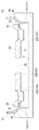
次に、図1に戻って、保持部材70について説明する。この保持部材70は、薄い鋼板がリング状に打ち抜かれて形成されており、更に軸方向に半抜き加工されることによって、その図示左手前側の一端に軸方向に面を有するフランジ状の第1座面部71が形成され、更にこの第1座面部71の外周縁部からは図示奥方側の他端に向けて半径方向外方側に傾斜状に延びる第2座面部72が形成された円筒型形状に形成されている。   Next, returning to FIG. 1, the holding member 70 will be described. The holding member 70 is formed by punching a thin steel plate into a ring shape, and is further half-punched in the axial direction, whereby a flange-shaped first having a surface in the axial direction at one end on the left front side in the figure. Cylindrical type in which a seat surface portion 71 is formed, and a second seat surface portion 72 extending from the outer peripheral edge of the first seat surface portion 71 toward the other end on the back side in the figure is inclined in the radially outward direction. It is formed into a shape.

ここで、図5に示されるように、第1座面部71は、保持部材70の円筒内にガイド20が組み付けられることにより、このガイド20の円環部22の外盤面と軸方向に対面する位置に配置形成されている。そして、上述した傾斜方向に延びる第2座面部72は、保持部材70の円筒内にラチェット10が組み付けられることにより、このラチェット10の支え部15の内盤面の外周縁部に形成された傾斜面15aに面当接するように形成されている。したがって、上記構成の保持部材70の円筒内にガイド20が軸方向に挿通されることにより、円環部22が第1座面部71と当接する位置でガイド20の挿通位置が位置決めされることとなる。   Here, as shown in FIG. 5, the first seat surface portion 71 faces the outer plate surface of the annular portion 22 of the guide 20 in the axial direction by assembling the guide 20 in the cylinder of the holding member 70. It is arranged at the position. The above-described second seat surface portion 72 extending in the inclined direction is formed on the outer peripheral edge portion of the inner plate surface of the support portion 15 of the ratchet 10 by assembling the ratchet 10 in the cylinder of the holding member 70. It is formed so as to be in surface contact with 15a. Therefore, when the guide 20 is inserted into the cylinder of the holding member 70 having the above configuration in the axial direction, the insertion position of the guide 20 is positioned at a position where the annular portion 22 contacts the first seat surface portion 71. Become.

そして、保持部材70の円筒内にラチェット10が軸方向に挿通されることにより、このラチェット10に形成された傾斜面15aが第2座面部72と面当接する位置でラチェット10の挿通位置が位置決めされることとなる。そして、上述したガイド20及びラチェット10の挿通後に、保持部材70の受入口側の開口端部を半径方向内方側に折り曲げ処理してラチェット10の支え部15の外盤面にかしめることにより、保持部材70がラチェット10と一体的となって結合固定される。   Then, when the ratchet 10 is inserted into the cylinder of the holding member 70 in the axial direction, the insertion position of the ratchet 10 is positioned at a position where the inclined surface 15 a formed on the ratchet 10 comes into surface contact with the second seat surface portion 72. Will be. Then, after the guide 20 and the ratchet 10 are inserted, the opening end portion on the receiving side of the holding member 70 is bent inward in the radial direction and caulked on the outer plate surface of the support portion 15 of the ratchet 10. The holding member 70 is coupled and fixed integrally with the ratchet 10.

これにより、ラチェット10及びガイド20の外周部が、保持部材70の第1座面部71及び第2座面部72と上述した折り曲げ処理された折曲面部73とによって軸方向に挟み込まれて外れ止めされた状態として保持される。ここで、ガイド20の円環部22は、ラチェット10の円筒部12と保持部材70の第1座面部71との間に軸方向の僅かな隙間を有して組み付けられるようになっている。これにより、ガイド20のラチェット10に対する回転移動が保持部材70との摺動摩擦によって阻害されることなくスムーズに行えるようになっている。   Accordingly, the outer peripheral portions of the ratchet 10 and the guide 20 are sandwiched in the axial direction and prevented from being separated by the first seat surface portion 71 and the second seat surface portion 72 of the holding member 70 and the folded curved surface portion 73 described above. It is held as a state. Here, the annular portion 22 of the guide 20 is assembled with a slight gap in the axial direction between the cylindrical portion 12 of the ratchet 10 and the first seat surface portion 71 of the holding member 70. Thereby, the rotational movement of the guide 20 with respect to the ratchet 10 can be smoothly performed without being hindered by the sliding friction with the holding member 70.

ここで、第1座面部71には、その周方向の複数箇所に、内盤側の面から軸方向に点状に突出する突部71a・・が形成されている。これにより、ガイド20の円環部22は、第1座面部71に対しては各突部71a・・によって点で接触するようになっており、その回転時の接触による摺動抵抗の影響が小さく抑えられるようになっている。   Here, the first seat surface portion 71 is formed with protrusions 71a,. As a result, the annular portion 22 of the guide 20 comes into contact with the first seat surface portion 71 at each point by the protrusions 71a, and the influence of sliding resistance due to the contact at the time of rotation is exerted. It is designed to be kept small.

ところで、上述したリクライニング装置4は、図8〜図12に示されるように、支え具Jに保持部材70をセットして、この保持部材70に各構成部品を重力方向に順にセットしていくことによって組み付けられている。具体的には、先ず、図8に示されるように、保持部材70を、支え具Jに対して、その受入口側の開口部が上方側を向くようにしてセットする。ここで、支え具Jには、保持部材70の第2座面部72の背面の形状に即して傾斜した支持面Jaが形成されている。   By the way, as shown in FIGS. 8 to 12, the reclining device 4 described above sets the holding member 70 on the support member J, and sets each component in order on the holding member 70 in the direction of gravity. It is assembled by. Specifically, first, as shown in FIG. 8, the holding member 70 is set with respect to the support J such that the opening on the receiving side faces upward. Here, the support member J is formed with a support surface Ja inclined according to the shape of the back surface of the second seat surface portion 72 of the holding member 70.

したがって、保持部材70を、この支え具Jの傾斜した支持面Jaに第2座面部72の傾斜した背面を当てがうようにしてセットすることにより、保持部材70が支持面Jaによって軸方向に支えられた状態として支え具Jにセットされる。   Therefore, the holding member 70 is set in the axial direction by the support surface Ja by setting the holding member 70 so that the inclined back surface of the second seat surface portion 72 is applied to the inclined support surface Ja of the support member J. The support J is set as a supported state.

そして次に、図9に示されるように、この保持部材70の円筒内部にガイド20を挿通してセットする。このとき、ガイド20は、その円環部22の外盤面が保持部材70の第1座面部71(突部71a・・)と当接することにより、その挿通位置が位置決めされた状態として保持部材70にセットされる。次に、図10に示されるように、ガイド20の円盤部21上にポール30,30、スライドカム40及びヒンジカム50を載置してセットする。このとき、各ポール30,30は、ガイド20に形成されたポール溝23a,23a内に収容されることにより、ガイド20に対する組み付け位置が位置決めされた状態としてセットされる。   Then, as shown in FIG. 9, the guide 20 is inserted and set inside the cylinder of the holding member 70. At this time, the guide 20 has the holding member 70 in a state where its insertion position is positioned by the outer plate surface of the annular portion 22 coming into contact with the first seat surface portion 71 (projection 71a...) Of the holding member 70. Set to Next, as shown in FIG. 10, the poles 30, 30, the slide cam 40 and the hinge cam 50 are placed and set on the disk portion 21 of the guide 20. At this time, each of the poles 30 and 30 is set in a state in which the assembly position with respect to the guide 20 is positioned by being accommodated in the pole grooves 23 a and 23 a formed in the guide 20.

また、スライドカム40は、ガイド20に形成されたスライドカム溝23b内に収容されることにより、ガイド20に対する組み付け位置が位置決めされた状態としてセットされる。また、ヒンジカム50は、スライドカム40のカム孔41とガイド20の貫通孔25とに貫通して挿通されることにより、スライドカム40やガイド20に対する組み付け位置が位置決めされた状態としてセットされる。そして次に、図11に示されるように、ガイド20の円環部22に嵌め込むようにしてラチェット10をセットする。   Further, the slide cam 40 is set in a state in which the assembly position with respect to the guide 20 is positioned by being accommodated in the slide cam groove 23b formed in the guide 20. Further, the hinge cam 50 is set in a state in which the assembly position with respect to the slide cam 40 and the guide 20 is positioned by being inserted through the cam hole 41 of the slide cam 40 and the through hole 25 of the guide 20. Then, as shown in FIG. 11, the ratchet 10 is set so as to be fitted into the annular portion 22 of the guide 20.

このとき、ラチェット10は、その支え部15の円筒内にガイド20の円環部22を嵌め込むように組み付けることにより、支え部15の傾斜面15aが保持部材70の傾斜した第2座面部72に面当接してその挿通位置が位置決めされた状態として保持部材70にセットされる。そして次に、図12に示されるように、保持部材70の受入口側の開口端部をかしめ機Mによって半径方向内方側に折り曲げ処理してラチェット10の支え部15の外盤面にかしめることにより、ラチェット10とガイド20とが保持部材70によって外れ止めされた状態として組み付けられる。   At this time, the ratchet 10 is assembled so that the annular portion 22 of the guide 20 is fitted into the cylinder of the support portion 15, whereby the inclined surface 15 a of the support portion 15 is inclined to the second seat surface portion 72 where the holding member 70 is inclined. The holding member 70 is set in a state in which the insertion position is positioned by abutting the surface of the holding member 70. Then, as shown in FIG. 12, the opening end portion on the receiving side of the holding member 70 is bent inward in the radial direction by the caulking machine M and caulked to the outer plate surface of the support portion 15 of the ratchet 10. Thus, the ratchet 10 and the guide 20 are assembled in a state in which they are prevented from coming off by the holding member 70.

このとき、保持部材70の開口端部のかしめ処理は、第2座面部72の背面に沿って傾斜向きに当てがわれた支え具Jの支持面Jaによって軸方向に支えられた状態で行われるため、精度良くかしめ処理が行われるようになっている。このように、リクライニング装置4は、各構成部品を重力方向に順にセットしていくことによって組み付けることができ、その組み付けの途中で組み付けた構成部品全体を引っ繰り返す反転作業をしなくても、外れ止めした状態に組み付けることができる。   At this time, the caulking process of the opening end portion of the holding member 70 is performed in a state of being supported in the axial direction by the support surface Ja of the support member J applied in an inclined direction along the back surface of the second seat surface portion 72. Therefore, the caulking process is performed with high accuracy. In this way, the reclining device 4 can be assembled by sequentially setting each component in the direction of gravity, and the reclining device 4 can be detached without performing a reversing operation that repeats the entire component assembled in the middle of the assembly. Can be assembled in a stopped state.

このように、本実施例の車両用シートの連結装置であるリクライニング装置4によれば、保持部材70の第2座面部72の背面が傾斜面となっており、折曲面部73のかしめ処理時には、この傾斜した第2座面部72の背面に支え具Jが傾斜向きに当てがわれる。これにより、例えば第2座面部72の背面が軸方向に向いて形成される構成と比べると、第2座面部72の背面に支え具Jを広く当てがうことができる。   Thus, according to the reclining device 4 that is the vehicle seat coupling device of the present embodiment, the back surface of the second seat surface portion 72 of the holding member 70 is an inclined surface, and during the caulking process of the folding surface portion 73 The support member J is applied to the inclined back surface of the second seat surface portion 72 in an inclined direction. Thereby, compared with the structure by which the back surface of the 2nd seat surface part 72 is formed in the axial direction, for example, the support J can be widely applied to the back surface of the 2nd seat surface part 72.

すなわち、第2座面部72の背面が軸方向に向いて形成される場合には、第1座面部71の外周縁部から第2座面部72に向けて軸方向に折り返される面部の半径方向の肉厚や、その折り返された面部から更に半径方向外方側に第2座面部72が折り返される折曲点の丸角によって、第2座面部72の背面に支え具Jを当てがうことのできる軸方向の面が狭められるからである。また、保持部材70の第2座面部72の背面を、第1座面部71の背面から屈曲して傾斜方向に真っ直ぐに延びる形状としたことにより、この第2座面部72の背面に支え具Jを広く当てがうことができる。   That is, when the back surface of the second seat surface portion 72 is formed in the axial direction, the radial direction of the surface portion that is folded back in the axial direction from the outer peripheral edge portion of the first seat surface portion 71 toward the second seat surface portion 72. The support J is applied to the back surface of the second seat surface portion 72 by the wall thickness or the round corner of the bending point at which the second seat surface portion 72 is folded further outward in the radial direction from the folded surface portion. This is because the possible axial surface is narrowed. Further, the back surface of the second seat surface portion 72 of the holding member 70 is bent from the back surface of the first seat surface portion 71 and extends straight in the inclined direction, so that the support J Can be widely applied.

以上、本発明の実施形態を一つの実施例を用いて説明したが、本発明は上記実施例のほか各種の形態で実施できるものである。例えば、上記実施例では、本発明の車両用シートの連結装置を、シートバック2をシートクッション3に対して背凭れ角度調整可能に連結するリクライニング装置4として適用したものを示した。しかし、この連結装置は、シートバック2を車体フロアに対して背凭れ角度調整可能に連結する用途にも適用することができる。   As mentioned above, although the embodiment of the present invention has been described using one example, the present invention can be implemented in various forms in addition to the above example. For example, in the above embodiment, the vehicle seat connecting device of the present invention is applied as the reclining device 4 that connects the seat back 2 to the seat cushion 3 so that the backrest angle can be adjusted. However, this connecting device can also be applied to applications in which the seat back 2 is connected to the vehicle floor so that the backrest angle can be adjusted.

また、連結装置を、シート本体を車体フロアに対して旋回方向に回転させられるように連結する用途にも適用することができる。また、連結装置を、着座者の下腿部を下方側から持ち上げて支持するいわゆるオットマン装置をシートクッション3や車体フロアに対して起倒回動可能に連結する用途にも適用することができる。また、ラチェット10に形成した支え部15によってガイド20の円環部22を外周側から囲い込んで支えるようにした構成を示したが、支え部15に相当する構成をガイド20側に形成して、ラチェット10の円筒部12をこのガイド20に形成した支え部によって外周側から囲い込んで支えるように構成することもできる。この場合には、例えば保持部材70の第1座面部71がラチェット10の円筒部12の外盤面に当てがわれ、第2座面部72がガイド20の支え部の内盤面に当てがわれ、折曲面部73が同ガイド20の支え部の外盤面にかしめられて固定される構成となる。   Further, the connecting device can be applied to an application for connecting the seat body so as to be rotated in the turning direction with respect to the vehicle body floor. Further, the connecting device can be applied to an application in which a so-called ottoman device that lifts and supports the lower leg of a seated person from below is connected to the seat cushion 3 or the vehicle body floor so as to be able to be turned upside down. Moreover, although the structure which enclosed and supported the annular part 22 of the guide 20 from the outer peripheral side by the support part 15 formed in the ratchet 10 was shown, the structure corresponded to the support part 15 is formed in the guide 20 side. The cylindrical portion 12 of the ratchet 10 can be enclosed and supported from the outer peripheral side by a support portion formed on the guide 20. In this case, for example, the first seat surface portion 71 of the holding member 70 is applied to the outer plate surface of the cylindrical portion 12 of the ratchet 10, and the second seat surface portion 72 is applied to the inner plate surface of the support portion of the guide 20. The curved surface portion 73 is fixed by being caulked to the outer surface of the support portion of the guide 20.

また、ラチェット10に支え部15を形成せずに、単にラチェット10とガイド20とを円筒部12と円環部22とが軸方向に対面するように組み付けて、これらを保持部材70によって軸方向にも半径方向にも外れ止めできるようにした構成であってもよい。また、図13に示されるように、保持部材70の第2座面部72を厚肉化して形成し、第2座面部72がラチェット10(他方側の連結部材)の内盤面に対しては軸方向に面当てされるが、その背面に形成された傾斜面によって支え具Jの支持面Jaに対してはその傾斜面に即して傾斜向きに当てがわれるように構成することもできる。これにより、ラチェット10(他方側の連結部材)の内盤面に傾斜面15a(図5参照)を形成することなく、支え具Jを保持部材70に広く当てがうことができる。   Further, without forming the support portion 15 on the ratchet 10, the ratchet 10 and the guide 20 are simply assembled so that the cylindrical portion 12 and the annular portion 22 face each other in the axial direction, and these are held by the holding member 70 in the axial direction. Alternatively, it may be configured such that it can be prevented from coming off in the radial direction. Further, as shown in FIG. 13, the second seating surface portion 72 of the holding member 70 is formed to be thick, and the second seating surface portion 72 is a shaft with respect to the inner board surface of the ratchet 10 (the other side connecting member). Although it faces to a direction, it can also be comprised so that it may be applied to the support surface Ja of the support tool J in the inclination direction according to the inclined surface with the inclined surface formed in the back surface. Accordingly, the support member J can be widely applied to the holding member 70 without forming the inclined surface 15a (see FIG. 5) on the inner surface of the ratchet 10 (the other side connecting member).

また、連結装置として、ラチェット10の内周歯面12aに各ポール30,30の外周歯面30a,30aを噛合ロックさせて回転留めを行うロック解除操作タイプのリクライニング装置4を例示したが、特開2008−18055公報に開示されているように、外歯車を有する外歯部材(一方側の連結部材)が内歯車を有する内歯部材(他方側の連結部材)の内周歯面上を噛合位置を変えながら回転(公転)運動し、両者を噛合させる方向に押さえ付ける操作力によって回転留めを行ういわゆる無段階式のリクライニング装置にも本発明の構成を適用することができる。   Further, as an example of the connecting device, the unlocking operation type reclining device 4 is illustrated in which the inner peripheral tooth surface 12a of the ratchet 10 is engaged and locked with the outer peripheral tooth surfaces 30a, 30a of the poles 30 and 30. As disclosed in Japanese Unexamined Patent Application Publication No. 2008-18055, an external tooth member (one side connecting member) having an external gear meshes with an inner peripheral tooth surface of an internal tooth member (other side connecting member) having an internal gear. The configuration of the present invention can also be applied to a so-called stepless reclining device that rotates (revolves) while changing its position and performs rotation stop by an operating force that presses in a direction in which both are engaged.

実施例1のリクライニング装置の分解斜視図である。1 is an exploded perspective view of a reclining device according to Embodiment 1. FIG. 車両用シートの概略構成を表した斜視図である。It is a perspective view showing the schematic structure of the vehicle seat. リクライニング装置の組み付け状態を表した斜視図である。It is a perspective view showing the assembly state of the reclining device. リクライニング装置の組み付け状態を表した斜視図である。It is a perspective view showing the assembly state of the reclining device. 図4のV-V線断面図である。It is the VV sectional view taken on the line of FIG. リクライニング装置のロック状態を表した図3のVI-VI線断面図である。It is the VI-VI sectional view taken on the line of FIG. 3 showing the locked state of the reclining apparatus. リクライニング装置のロックを解除した状態を表した断面図である。It is sectional drawing showing the state which unlocked the reclining apparatus. 保持部材の組み付け工程を表した工程図である。It is process drawing showing the assembly | attachment process of the holding member. ガイドの組み付け工程を表した工程図である。It is process drawing showing the assembly | attachment process of a guide. 各ロック部品の組み付け工程を表した工程図である。It is process drawing showing the assembly | attachment process of each lock component. ラチェットの組み付け工程を表した工程図である。It is process drawing showing the assembly | attachment process of a ratchet. 保持部材のかしめ処理工程を表した工程図である。It is process drawing showing the caulking process process of a holding member. リクライニング装置の変形実施例を示した構成図である。It is the block diagram which showed the modification Example of the reclining apparatus.

符号の説明Explanation of symbols

1 車両用シート
2 シートバック
2f バックフレーム(二つの対象部材の一方側)
2a ダボ孔
2b Dダボ孔
2c 貫通孔
3 シートクッション
3f クッションフレーム(二つの対象部材の他方側)
3a ダボ孔
3b Dダボ孔
3c 貫通孔
4 リクライニング装置(車両用シートの連結装置)
4c 操作軸
4r 連結ロッド
5 操作レバー
10 ラチェット(他方側の連結部材)
11 円盤部
12 円筒部
12a 内周歯面
12b 突出平面
13a ダボ
13b Dダボ
14 貫通孔
15 支え部
15a 傾斜面
20 ガイド(一方側の連結部材)
21 円盤部
21a〜21d 案内壁
22 円環部
23 ガイド溝
23a ポール溝
23b スライドカム溝
24a ダボ
24b Dダボ
25 貫通孔
26 ばね掛部
30 ポール
30a 外周歯面
31 掛部
32 脚部
40 スライドカム
41 カム孔
42 肩部
43 溝部
44 フック
50 ヒンジカム
51 ばね掛部
52 操作突起
60 巻きばね
61 内端
62 外端
70 保持部材
71 第1座面部
71a 突部
72 第2座面部
73 折曲面部
J 支え具
Ja 支持面
M かしめ機
DESCRIPTION OF SYMBOLS 1 Vehicle seat 2 Seat back 2f Back frame (one side of two object members)
2a Dowel hole 2b D Dowel hole 2c Through hole 3 Seat cushion 3f Cushion frame (the other side of the two target members)
3a Dowel hole 3b D Dowel hole 3c Through hole 4 Reclining device (vehicle seat coupling device)
4c Operation shaft 4r Connection rod 5 Operation lever 10 Ratchet (connection member on the other side)
DESCRIPTION OF SYMBOLS 11 Disk part 12 Cylindrical part 12a Inner peripheral tooth surface 12b Projection plane 13a Dowel 13b D Dowel 14 Through-hole 15 Support part 15a Inclined surface 20 Guide (one side connection member)
21 disk part 21a-21d guide wall 22 ring part 23 guide groove 23a pole groove 23b slide cam groove 24a dowel 24b D dowel 25 through hole 26 spring hook part 30 pole 30a outer peripheral tooth surface 31 hook part 32 leg part 40 slide cam 41 Cam hole 42 Shoulder portion 43 Groove portion 44 Hook 50 Hinge cam 51 Spring hook portion 52 Operation protrusion 60 Winding spring 61 Inner end 62 Outer end 70 Holding member 71 First seat surface portion 71a Projection portion 72 Second seat surface portion 73 Folding curved surface portion J Supporting tool Ja Support surface M Caulking machine

Claims (3)

二つの対象部材を互いに相対回転可能に連結する車両用シートの連結装置であって、
前記二つの対象部材の一方側或いは他方側にそれぞれ一体的に連結されて互いに相対回転可能に盤合わせ方向に組付けられる少なくとも円盤状部分を有する二枚の連結部材と、
該二枚の連結部材を軸方向に外れ止めする保持部材と、を有し、
前記二枚の連結部材は、互いの間に設けられた回転留め構造の作動状態によって互いの相対回転が行われる状態と留められる状態とに切り換えられるようになっており、
前記保持部材は、軸方向に面を有する第1座面部と第2座面部とをそれぞれ前記一方側の連結部材の外盤面と前記他方側の連結部材の内盤面とに当てがえた状態で該他方側の連結部材の外盤面に軸方向に面を当てがうように折曲面部を折り曲げてかしめることにより該他方側の連結部材に軸方向に一体的に連結されており、
該保持部材の折曲面部のかしめ処理は前記保持部材の第2座面部の背面に支え具が軸方向に当てがわれて行われ、該支え具が当てがわれる第2座面部の背面は前記第1座面部から半径方向外方側に向けて軸方向に傾斜状に延びる傾斜面として形成されていることを特徴とする車両用シートの連結装置。
A vehicle seat coupling device that couples two target members such that they can rotate relative to each other,
Two connecting members having at least a disk-shaped portion that are integrally connected to one side or the other side of the two target members and assembled to each other so as to be rotatable relative to each other;
A holding member for preventing the two connecting members from coming off in the axial direction,
The two connecting members are configured to be switched between a state in which relative rotation is performed and a state in which the relative rotation is performed according to an operation state of a rotation retaining structure provided between each other,
The holding member is in a state where the first seat surface portion and the second seat surface portion having surfaces in the axial direction are respectively applied to the outer board surface of the one side connecting member and the inner board surface of the other side connecting member. It is integrally connected to the connecting member on the other side in the axial direction by bending and crimping the bent surface portion so that the surface is applied to the outer board surface of the connecting member on the other side in the axial direction.
The folding process of the folding surface portion of the holding member is performed by applying a support member in the axial direction to the back surface of the second seat surface portion of the holding member, and the back surface of the second seat surface portion to which the support member is applied is A vehicular seat coupling device, wherein the vehicular seat coupling device is formed as an inclined surface extending in an axially inclined manner from the first seat surface portion toward the radially outward side.
請求項1に記載の車両用シートの連結装置であって、
前記保持部材の第2座面部が当てがわれる前記他方側の連結部材の内盤面はその背面となる外盤面に向けて半径方向外方側に傾斜して形成されており、この傾斜した内盤面に前記保持部材の第2座面部が傾斜向きに当てがわれて、この傾斜した第2座面部の背面に前記支え具が傾斜向きに当てがわれるようになっていることを特徴とする車両用シートの連結装置。
The vehicle seat coupling device according to claim 1,
The inner plate surface of the other side connecting member to which the second seating surface portion of the holding member is applied is formed so as to be inclined radially outward toward the outer plate surface serving as the back surface of the inner plate surface. The holding member is applied to the second seat surface portion in an inclined direction, and the support member is applied to the inclined rear surface of the inclined second seat surface portion. Sheet coupling device.
請求項1又は請求項2に記載の車両用シートの連結装置であって、
前記支え具が当てがわれる前記保持部材の第2座面部の背面は、前記第1座面部の背面から屈曲して傾斜方向に真っ直ぐに延びて形成されていることを特徴とする車両用シートの連結装置。
The vehicle seat coupling device according to claim 1 or 2,
The back surface of the second seat surface portion of the holding member to which the support member is applied is formed by bending from the back surface of the first seat surface portion and extending straight in the inclined direction. Connecting device.
JP2008100047A 2008-04-08 2008-04-08 Coupling device of vehicle seat Pending JP2009247648A (en)

Priority Applications (1)

Application Number Priority Date Filing Date Title
JP2008100047A JP2009247648A (en) 2008-04-08 2008-04-08 Coupling device of vehicle seat

Applications Claiming Priority (1)

Application Number Priority Date Filing Date Title
JP2008100047A JP2009247648A (en) 2008-04-08 2008-04-08 Coupling device of vehicle seat

Publications (1)

Publication Number Publication Date
JP2009247648A true JP2009247648A (en) 2009-10-29

Family

ID=41308880

Family Applications (1)

Application Number Title Priority Date Filing Date
JP2008100047A Pending JP2009247648A (en) 2008-04-08 2008-04-08 Coupling device of vehicle seat

Country Status (1)

Country Link
JP (1) JP2009247648A (en)

Cited By (1)

* Cited by examiner, † Cited by third party
Publication number Priority date Publication date Assignee Title
JP2015067144A (en) * 2013-09-30 2015-04-13 トヨタ紡織株式会社 Recliner

Cited By (1)

* Cited by examiner, † Cited by third party
Publication number Priority date Publication date Assignee Title
JP2015067144A (en) * 2013-09-30 2015-04-13 トヨタ紡織株式会社 Recliner

Similar Documents

Publication Publication Date Title
JP5315757B2 (en) Vehicle seat coupling device
JP5309665B2 (en) Vehicle seat coupling device
JP5167948B2 (en) Vehicle seat coupling device
JP5177144B2 (en) Rotating locking device for vehicle seat
JP5195761B2 (en) Reclining device for vehicle seat
JP2010035738A (en) Coupling device of vehicle seat
JP2010052454A (en) Coupling device of vehicle seat
JP2009138758A (en) Rotation stopper
JP5256876B2 (en) Vehicle seat coupling device
JP5217632B2 (en) Vehicle seat coupling device
JP2009247648A (en) Coupling device of vehicle seat
JP5223423B2 (en) Vehicle seat coupling device
JP5176560B2 (en) Vehicle seat coupling device
JP4720659B2 (en) Connecting device
JP5130956B2 (en) Vehicle seat coupling device
JP5169232B2 (en) Vehicle seat coupling device
JP5169233B2 (en) Vehicle seat coupling device
JP5338201B2 (en) Vehicle seat coupling device
JP5338212B2 (en) Vehicle seat coupling device
JP5278085B2 (en) Vehicle seat coupling device
JP5104321B2 (en) Vehicle seat coupling device
JP2009279183A (en) Coupling device of vehicle seat
JP2009285025A (en) Coupling device of vehicle seat
JP2010064539A (en) Connection device for vehicle seat
JP2009061007A (en) Rotation stop device of vehicle seat