JP2009243711A - Combustion system - Google Patents
Combustion system Download PDFInfo
- Publication number
- JP2009243711A JP2009243711A JP2008087919A JP2008087919A JP2009243711A JP 2009243711 A JP2009243711 A JP 2009243711A JP 2008087919 A JP2008087919 A JP 2008087919A JP 2008087919 A JP2008087919 A JP 2008087919A JP 2009243711 A JP2009243711 A JP 2009243711A
- Authority
- JP
- Japan
- Prior art keywords
- gas
- wobbe index
- fuel gas
- nozzle
- adjusting
- Prior art date
- Legal status (The legal status is an assumption and is not a legal conclusion. Google has not performed a legal analysis and makes no representation as to the accuracy of the status listed.)
- Pending
Links
Images


Abstract
Description
本発明は、ノズルより噴射された燃料ガスを燃焼する燃焼装置と、該燃焼装置の上記ノズルに燃料ガスを供給する燃料供給装置とを備える燃焼システムに関するものである。 The present invention relates to a combustion system including a combustion device that burns fuel gas injected from a nozzle, and a fuel supply device that supplies the fuel gas to the nozzle of the combustion device.
ガスタービン、ガスエンジンあるいはボイラ等の燃焼装置を備える燃焼システムは、例えば、工場等で発生した副生ガスの燃焼に用いられる。そして、副生ガスの燃焼によって取り出された熱エネルギを用いて発電や水蒸気の生成が行われる。 A combustion system including a combustion device such as a gas turbine, a gas engine, or a boiler is used for combustion of by-product gas generated in a factory or the like, for example. Then, power generation and water vapor generation are performed using the thermal energy extracted by the combustion of the byproduct gas.
ところで、副生ガスの組成は、工場等の稼動条件や時期によって変動しやすい。副生ガスの組成が変動すると、燃焼装置において所望の燃焼状態が得られなくなり、所望の熱エネルギが取り出せなくなる場合がある。つまり、燃焼システムにおいては、燃料ガスの組成が変動する場合があり、このような場合には所望の熱エネルギが取り出せなくなる場合がある。
このため、特許文献1には、燃料ガスに対して、発熱量の高いガスを追加したり、発熱量の低いガスを追加することによって、燃料ガスの熱量を調節し、燃料ガスの組成が変動して熱量が変化した場合であっても、所望の燃焼状態を維持する方法が提案されている。
For this reason, in Patent Document 1, the amount of heat of the fuel gas is adjusted by adding a gas having a high calorific value or a gas having a low calorific value to the fuel gas, and the composition of the fuel gas varies. Even when the amount of heat changes, a method for maintaining a desired combustion state has been proposed.
しかしながら、燃料ガスに上述のように熱量を調節する目的で他のガスを混合した場合には、燃料ガスのウォッベ指数が変化してしまう。燃料ガスをノズルから噴射するためには、燃料ガスのウォッベ指数をノズルの噴射可能範囲に合わせる必要があるが、上述のように他のガスを燃料ガスに混合した場合には、ノズルの噴射可能範囲を超えてウォッベ指数が変化する場合がある。このため、特許文献1の方法では、ウォッベ指数の変化に応じてノズルを交換する必要が生じる。 However, when other gases are mixed with the fuel gas for the purpose of adjusting the amount of heat as described above, the Wobbe index of the fuel gas changes. In order to inject fuel gas from the nozzle, it is necessary to adjust the wobbe index of the fuel gas to the nozzle injectable range. However, if other gases are mixed with the fuel gas as described above, the nozzle can be injected. The Wobbe index may change beyond the range. For this reason, in the method of Patent Document 1, it is necessary to replace the nozzle according to the change in the Wobbe index.
一方で特許文献2には、燃料ガスに水を混合することによって燃料ガスのウォッベ指数を調節する方法が提案されている。
しかしながら、特許文献2の方法では、燃料ガスの組成が熱量の低下する方向に変化した場合には、ウォッベ指数の調節のために水を混合することによって燃料ガスの熱量がさらに低下されてしまう。これによって、所望の燃焼状態を維持することができなくなる。また、燃料ガスの組成が熱量の低下する方向に変化している場合には、水を混合することによってのみでは十分にウォッベ指数を調節することができない。
On the other hand, Patent Document 2 proposes a method of adjusting the Wobbe index of the fuel gas by mixing water with the fuel gas.
However, in the method of Patent Document 2, when the composition of the fuel gas changes in a direction in which the amount of heat decreases, the amount of heat of the fuel gas is further decreased by mixing water for adjusting the Wobbe index. As a result, the desired combustion state cannot be maintained. In addition, when the composition of the fuel gas changes in the direction in which the amount of heat decreases, the Wobbe index cannot be adjusted sufficiently only by mixing water.
本発明は、上述する問題点に鑑みてなされたもので、ノズルを介して噴射される燃料ガスを燃焼する燃焼装置を備える燃焼システムにおいて、ノズル交換を必要とせずかつ所望の燃焼状態を得ることを目的とする。 The present invention has been made in view of the above-described problems, and in a combustion system including a combustion device that burns fuel gas injected through a nozzle, nozzle replacement is not required and a desired combustion state is obtained. With the goal.
上記目的を達成するために、本発明では、ノズルより噴射された燃料ガスを燃焼する燃焼装置と、該燃焼装置の上記ノズルに燃料ガスを供給する燃料供給装置とを備える燃焼システムであって、上記燃料供給装置が、上記燃料ガスに熱量を調節するための熱量調節ガスを混合可能な熱量調節ガス混合手段と、上記燃料ガスにウォッベ指数を調節するためのウォッベ指数調節ガスを混合可能なウォッベ指数調節ガス混合手段と、上記ノズルに供給される上記燃料ガスのウォッベ指数が上記ノズルの噴射可能範囲となり、上記ノズルに供給される上記燃料ガスの熱量が上記燃焼装置の要求範囲となるように上記熱量調節ガス混合手段及び上記ウォッベ指数調節ガス混合手段を制御する制御手段とを備えることを特徴とする。 In order to achieve the above object, in the present invention, a combustion system comprising a combustion device for burning fuel gas injected from a nozzle, and a fuel supply device for supplying fuel gas to the nozzle of the combustion device, The fuel supply device includes a calorific value adjusting gas mixing means capable of mixing a calorific value adjusting gas for adjusting a calorific value with the fuel gas, and a wobbe capable of mixing a wobbe index adjusting gas for adjusting the Wobbe index with the fuel gas. The index adjusting gas mixing means and the Wobbe index of the fuel gas supplied to the nozzle are in the injectable range of the nozzle, and the amount of heat of the fuel gas supplied to the nozzle is in the required range of the combustion device And a control means for controlling the heat quantity adjusting gas mixing means and the Wobbe index adjusting gas mixing means.
このような特徴を有する本発明によれば、燃料ガスの組成が変化した場合であっても、その組成に応じて、ノズルに供給される燃料ガスのウォッベ指数がノズルの噴射可能範囲となり、ノズルに供給される燃料ガスの熱量が燃焼装置の要求範囲となるように調節される。なお、ここでの燃焼装置の要求範囲の熱量とは、燃焼装置において所望の燃焼状態が維持可能な範囲の熱量を意味する。 According to the present invention having such characteristics, even when the composition of the fuel gas changes, the Wobbe index of the fuel gas supplied to the nozzle becomes the nozzle injectable range according to the composition, and the nozzle The amount of heat of the fuel gas supplied to is adjusted so as to be within the required range of the combustion apparatus. The amount of heat in the required range of the combustion device here means the amount of heat in a range in which a desired combustion state can be maintained in the combustion device.
また、本発明においては、上記熱量調節ガスは、都市ガス、天然ガス、LPGあるいは水素ガスであるという構成を採用する。 Moreover, in this invention, the structure that the said calorie | heat amount adjustment gas is city gas, natural gas, LPG, or hydrogen gas is employ | adopted.
また、本発明においては、上記ウォッベ指数調節ガスは、水蒸気あるいは不活性ガスであるという構成を採用する。 In the present invention, the Wobbe index adjusting gas is water vapor or an inert gas.
本発明によれば、燃料ガスの組成が変化した場合であっても、その組成に応じて、ノズルに供給される燃料ガスのウォッベ指数がノズルの噴射可能範囲となり、ノズルに供給される燃料ガスの熱量が燃焼装置の要求範囲となるように調節される。
このため、ノズルを介して噴射される燃料ガスを燃焼する燃焼装置を備える燃焼システムにおいて、ノズル交換を必要とせずかつ所望の燃焼状態を得ることが可能となる。
According to the present invention, even when the composition of the fuel gas changes, the wobbe index of the fuel gas supplied to the nozzle becomes the injectable range of the nozzle according to the composition, and the fuel gas supplied to the nozzle The amount of heat is adjusted to be within the required range of the combustion device.
For this reason, in a combustion system provided with a combustion device that burns fuel gas injected through a nozzle, it is possible to obtain a desired combustion state without requiring nozzle replacement.
以下、図面を参照して、本発明に係る燃焼システムの一実施形態について説明する。なお、以下の図面においては、各部材を認識可能な大きさとするために、各部材の縮尺を適宜変更している。 Hereinafter, an embodiment of a combustion system according to the present invention will be described with reference to the drawings. In the following drawings, the scale of each member is appropriately changed in order to make each member a recognizable size.
図1は、本実施形態の燃焼システムSの概略構成を示す模式図である。この図に示すように本実施形態の燃焼システムSは、燃焼装置1と、燃料供給装置2とを備えている。 FIG. 1 is a schematic diagram showing a schematic configuration of a combustion system S of the present embodiment. As shown in this figure, the combustion system S of the present embodiment includes a combustion device 1 and a fuel supply device 2.
燃焼装置1は、本実施形態の燃焼システムSにおいては、ガスタービンによって構成されている。なお、燃焼装置1は、ガスタービンに限られるものではなく、ガスエンジン、ボイラあるいはガスコンロであっても良い。 The combustion apparatus 1 is configured by a gas turbine in the combustion system S of the present embodiment. The combustion apparatus 1 is not limited to a gas turbine, and may be a gas engine, a boiler, or a gas stove.
本実施形態において燃焼装置1は、圧縮機11、燃焼器12、タービン13を備えている。
圧縮機11は、外部から吸気した空気を加圧して圧縮空気とし、燃焼器12に供給する構成となっている。
燃焼器12は、圧縮機11から供給される圧縮空気と燃料ガスとを混合して燃焼させ、燃焼ガスをタービン13へ排出する。なお、燃焼器12は、内部に燃料ガスを噴射するためのノズル12aを複数備えている。そして、ノズル12aから噴射された燃料ガスを燃焼する構成となっている。
タービン13は、燃焼器12から供給される燃焼ガスの運動エネルギ及び圧力エネルギによって回転駆動されて、圧縮機11の駆動力と、燃焼装置1の外部の発電機等の負荷6の駆動力とを発生する構成となっている。
In the present embodiment, the combustion apparatus 1 includes a
The
The
The
なお、燃焼ガスG1としては、工場等で発生した副生ガスあるいは熱分解ガスが用いられ、具体的には、石油精製所にて副生される水素、窒素、酸素、一酸化炭素、二酸化炭素、メタンやエタン、プロパン、ブタン等の飽和炭化水素、エチレンやプロピレン、ブテン、ブタジエン等の不飽和炭化水素を主に含むガス(例えばFCC(流動接触分解)ガスやFLG(重質油熱分解)ガス)や余剰ブタンを主としたガス、製鉄所にて副生される水素、窒素、一酸化炭素、二酸化炭素、炭化水素、水分を主に含むガス(COG(コークス炉ガス)、BFG(高炉ガス)、LDG(転炉ガス))、電界苛性ソーダ工場や化学工場にて副生される水素または炭化水素を含む水素リッチガス、ゴミ処理場から副生される水素、窒素、一酸化炭素、二酸化炭素、炭化水素を主に含む熱分解ガス等が用いられる。 As the combustion gas G1, by-product gas or pyrolysis gas generated in a factory or the like is used. Specifically, hydrogen, nitrogen, oxygen, carbon monoxide, carbon dioxide produced as a by-product in an oil refinery is used. Gases mainly containing saturated hydrocarbons such as methane, ethane, propane and butane, and unsaturated hydrocarbons such as ethylene, propylene, butene and butadiene (for example, FCC (fluid catalytic cracking) gas and FLG (heavy oil pyrolysis)) Gas) and surplus butane, hydrogen, nitrogen, carbon monoxide, carbon dioxide, hydrocarbons, and gas mainly containing water (COG (coke oven gas), BFG (blast furnace) Gas), LDG (converter gas)), hydrogen-rich gas containing hydrogen or hydrocarbons by-produced at electric caustic soda factories and chemical factories, hydrogen by-produced from garbage disposal, nitrogen, carbon monoxide, and carbon dioxide , Pyrolysis gas or the like containing a hydrocarbon mainly are used.
燃料供給装置2は、燃焼装置1の燃焼器12が備えるノズル12aに燃料ガスを供給するものであり、熱量調節ガス混合装置3(熱量調節ガス混合手段)と、ウォッベ指数調節ガス混合装置4(ウォッベ指数調節ガス混合手段)と、制御装置5(制御手段)とを備えている。
The fuel supply device 2 supplies fuel gas to a
熱量調節ガス混合装置3は、燃料ガスG1に熱量を調節するための熱量調節ガスG2を混合するためのものであり、熱量調節ガスG2を供給する供給装置31と、該供給装置31から供給された熱量調節ガスG2を燃料ガスG1に混合する混合器32とを備えている。
なお、熱量調節ガスG2としては、例えば熱量を多く含んで単体にて燃焼可能なガスが用いられ、具体的には都市ガス、天然ガス、LPGあるいは水素ガスが用いられる。
The calorific value adjusting gas mixing device 3 is for mixing the calorific value adjusting gas G2 for adjusting the calorific value with the fuel gas G1, and is supplied from the supplying
As the calorific value adjusting gas G2, for example, a gas containing a large amount of heat and combustible alone is used, and specifically, city gas, natural gas, LPG or hydrogen gas is used.
ウォッベ指数調節ガス混合装置4は、燃料ガスG1にウォッベ指数を調節するためのウォッベ指数調節ガスG3を混合するためのものであり、ウォッベ指数調節ガスG3を供給する供給装置41と、該供給装置31から供給されたウォッベ指数調節ガスG3を燃料ガスG1に混合する混合器42とを備えている。
なお、ウォッベ指数調節ガスG3としては、例えば熱量が極めて小さくて単体にて燃焼しないガスが用いられ、具体的には水蒸気や不活性ガス(窒素ガスやアルゴンガス)等が用いられる。中でもウォッベ指数調節ガスG3として水蒸気を用いる場合には、燃焼装置1のタービン13から排出される燃焼ガスを用いて水蒸気を生成して用いることによって、エネルギ効率の向上を図ることが可能となる。また、中でもウォッベ指数調節ガスG3として水蒸気を用いる場合には、燃料ガスG1に含まれる不飽和炭化水素の熱によるコーキングを抑制する効果が期待できる。
The Wobbe index adjusting
As the Wobbe index adjusting gas G3, for example, a gas that has an extremely small amount of heat and does not burn alone is used, and specifically, water vapor, inert gas (nitrogen gas or argon gas), or the like is used. In particular, when water vapor is used as the Wobbe index adjusting gas G3, it is possible to improve energy efficiency by generating and using water vapor using the combustion gas discharged from the
なお、本実施形態の燃焼システムSにおいてウォッベ指数とは、燃料ガスG1の単位容積あたりの発熱量と、燃料ガスG1の比重あるいは比重及び温度をパラメータとする指数であり、ガスの発熱量を比重の平方根で除した形(下式(1))、またはガスの発熱量を比重とガス温度の乗数の平方根で除した形(下式(2))で表される。 In the combustion system S of the present embodiment, the Wobbe index is an index using the calorific value per unit volume of the fuel gas G1 and the specific gravity or specific gravity and temperature of the fuel gas G1 as parameters. (The following formula (1)) or the form obtained by dividing the calorific value of the gas by the square root of the multiplier of the specific gravity and the gas temperature (the following formula (2)).

制御装置5は、ノズル12aに供給される燃料ガスG1のウォッベ指数がノズル12aの噴射可能範囲となり、ノズル12aに供給される燃料ガスG1の熱量が燃焼装置1の要求範囲となるように熱量調節ガス混合装置3及びウォッベ指数調節ガス混合装置4を制御するものである。
なお、ここでの燃焼装置1の要求範囲の熱量とは、燃焼装置1の燃焼器12において所望の燃焼状態が維持され、負荷6に所望の駆動力が伝達可能な範囲の熱量を意味する。
The
Here, the amount of heat in the required range of the combustion device 1 means the amount of heat in a range in which a desired combustion state is maintained in the
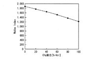
図2は、プロパンガスを燃料ガスG1とし、当該燃料ガスG1にウォッベ指数調節ガスG3として水蒸気を混合した場合における燃料ガスG1のウォッベ指数(Wobbe Index)と熱量(LHV)の変化を示すグラフである。また、図3は、n−ブタンガス、i−ブタンガス、1−ブテンガス、i−ブテンガスを燃料ガスG1とし、当該燃料ガスG1にウォッベ指数調節ガスG3として水蒸気を混合した場合における燃料ガスG1のウォッベ指数の変化を示すグラフである。
これらの図に示すように、燃料ガスG1に水蒸気を混合した場合には、ウォッベ指数が水蒸気の混合割合にほぼ比例して減少するが、熱量も水蒸気の混合割合に比例して減少することが分かる。
FIG. 2 is a graph showing changes in the Wobbe index and the amount of heat (LHV) of the fuel gas G1 when propane gas is the fuel gas G1 and water vapor is mixed with the fuel gas G1 as the Wobbe index adjusting gas G3. is there. FIG. 3 shows the Wobbe index of the fuel gas G1 when n-butane gas, i-butane gas, 1-butene gas, and i-butene gas are used as the fuel gas G1, and water vapor is mixed with the fuel gas G1 as the Wobbe index adjusting gas G3. It is a graph which shows the change of.
As shown in these figures, when water vapor is mixed with the fuel gas G1, the Wobbe index decreases in proportion to the mixing ratio of water vapor, but the amount of heat also decreases in proportion to the mixing ratio of water vapor. I understand.
また、図4は、プロパンガスを燃料ガスG1とし、当該燃料ガスG1に熱量調節ガスG2としてメタンガスを混合した場合における燃料ガスG1のウォッベ指数の変化を示すグラフである。
この図に示すように、燃料ガスG1に熱量調節ガスG2を混合した場合には、熱量調節ガスG2の混合割合に比例してウォッベ指数も減少する。
FIG. 4 is a graph showing a change in the Wobbe index of the fuel gas G1 when the propane gas is the fuel gas G1 and the fuel gas G1 is mixed with methane gas as the calorific value adjusting gas G2.
As shown in this figure, when the calorific value adjusting gas G2 is mixed with the fuel gas G1, the Wobbe index also decreases in proportion to the mixing ratio of the calorific value adjusting gas G2.
これらの図2〜図4から分かるように、燃料ガスG1に熱量調節ガスG2を混合した場合には燃料ガスの熱量と共にウォッベ指数も変化し、燃料ガスG1にウォッベ指数調節ガスG3を混合した場合にはウォッベ指数と共に熱量も変化する。
このため、制御装置5は、上述のような熱量とウォッベ指数の変化の関係を予め記憶しており、熱量調節ガス混合装置3及びウォッベ指数調節ガス混合装置4を制御する際に、例えば外部から入力される燃料ガスG1の組成に応じて、ノズル12aに供給される燃料ガスG1のウォッベ指数がノズル12aの噴射可能範囲となり、ノズル12aに供給される燃料ガスG1の熱量が燃焼装置1の要求範囲となるように、燃料ガスG1に供給する熱量調節ガスG2の量とウォッベ指数調節ガスG3の量とを決定する。
As can be seen from FIGS. 2 to 4, when the calorific value adjusting gas G2 is mixed with the fuel gas G1, the Wobbe index also changes with the calorific value of the fuel gas, and when the Wobbe index adjusting gas G3 is mixed with the fuel gas G1. The amount of heat changes with the Wobbe index.
For this reason, the
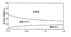
図5は、ウォッベ指数を一定(図5においては750)とするための、ブタンガス(燃料ガスG1)と、メタンガス(熱量調節ガスG2)と、水蒸気(ウォッベ指数調節ガスG3)との体積割合を示すグラフである。なお、図5において横軸は、ブタンガスに対するメタンの割合を示している。図6においてはウォッベ指数を800とするための、製油所副生FCCガス(燃料ガスG1)と、都市ガス(熱量調節ガスG2)と、水蒸気(ウォッベ指数調節ガスG3)との体積割合を示すグラフである。なお、図6において横軸は、FCCガスに対する都市ガスの割合を示している。
これらの図から分かるように、燃料ガスG1の量の減少に応じて熱量調節ガスG2の量を増加させて混合した場合であっても、ウォッベ指数調節ガスG3との体積割合を調節することによって、ウォッベ指数を一定とすることができる。副生ガスが上述のFLGガスやCOG、BFG、LDG、水素または炭化水素を含む水素リッチガス、熱分解ガス等の場合においても、熱量調節ガスG2として都市ガス、LNG、LPGあるいは水素ガスを用い、ウォッベ指数調節ガスG3として水蒸気、窒素ガスあるいはアルゴンガスを用いることによって同様にウォッベ指数を一定とすることができる。
つまり、燃料ガスG1の組成が変動して燃料ガスG1の熱量(流量)がどのように変化した場合であっても、熱量調節ガスG2を混合することにより燃料ガスG1の熱量が燃焼装置1の要求範囲となるように調節することができ、ウォッベ指数調節ガスG3を混合することにより燃料ガスG1のウォッベ指数がノズル12aの噴射可能範囲となるように調節することができる。
FIG. 5 shows the volume ratios of butane gas (fuel gas G1), methane gas (heat quantity adjustment gas G2), and water vapor (Wobbe index adjustment gas G3) to keep the Wobbe index constant (750 in FIG. 5). It is a graph to show. In FIG. 5, the horizontal axis indicates the ratio of methane to butane gas. In FIG. 6, the volume ratio of refinery by-product FCC gas (fuel gas G1), city gas (calorific value adjustment gas G2), and water vapor (Wobbe index adjustment gas G3) for setting the Wobbe index to 800 is shown. It is a graph. In FIG. 6, the horizontal axis represents the ratio of city gas to FCC gas.
As can be seen from these figures, by adjusting the volume ratio with the Wobbe index adjusting gas G3 even when the amount of the calorie adjusting gas G2 is increased and mixed in accordance with the decrease in the amount of the fuel gas G1. The Wobbe index can be constant. Even when the by-product gas is the above-mentioned FLG gas, COG, BFG, LDG, hydrogen-rich gas containing hydrogen or hydrocarbon, pyrolysis gas, etc., city gas, LNG, LPG or hydrogen gas is used as the calorie control gas G2. Similarly, by using water vapor, nitrogen gas or argon gas as the Wobbe index adjusting gas G3, the Wobbe index can be made constant.
That is, even if the composition of the fuel gas G1 fluctuates and the amount of heat (flow rate) of the fuel gas G1 changes, the amount of heat of the fuel gas G1 can be reduced by mixing the heat amount adjustment gas G2. It can be adjusted to be within the required range, and by mixing the Wobbe index adjusting gas G3, the Wobbe index of the fuel gas G1 can be adjusted to be within the injectable range of the
このような構成を有する本実施形態の燃焼システムSにおいては、制御装置5は、予め入力された燃料ガスG1の組成に応じて、ノズル12aに供給される燃料ガスG1のウォッベ指数がノズル12aの噴射可能範囲となり、ノズル12aに供給される燃料ガスG1の熱量が燃焼装置1の要求範囲となるような、熱量調節ガスG2の混合量とウォッベ指数調節ガスG3の混合量を決定し、この決定された混合量の熱量調節ガスG2とウォッベ指数調節ガスG3が燃料ガスG1に供給されるように、熱量調節ガス混合装置3及びウォッベ指数調節ガス混合装置4を制御する。
この結果、燃料ガスG1には、ウォッベ指数がノズル12aの噴射可能範囲となり、熱量が燃焼装置1の要求範囲となるように熱量調節ガスG2とウォッベ指数調節ガスG3が混合され、その後、燃焼装置1の燃焼器12のノズル12aに供給される。
このように、燃料供給装置2は、ウォッベ指数がノズル12aの噴射可能範囲とされ、熱量が燃焼装置1の要求範囲とされた燃料ガスG1を燃焼装置1に供給する。
In the combustion system S of the present embodiment having such a configuration, the
As a result, the fuel gas G1 is mixed with the calorific value adjusting gas G2 and the Wobbe index adjusting gas G3 so that the Wobbe index falls within the injectable range of the
As described above, the fuel supply device 2 supplies the combustion device 1 with the fuel gas G1 in which the Wobbe index is in the injectable range of the
燃焼装置1の燃焼器12のノズル12aに供給された燃料ガスG1は、燃焼器12の内部に噴射され圧縮機11から供給される圧縮空気と混合されて燃焼される。そして、当該燃焼によって生成された燃焼ガスがタービン13に供給されることでタービンが駆動力を生成して当該駆動力が圧縮機11及び負荷6に伝達される。
この際、燃焼器12のノズル12aに供給される燃料ガスG1は、ウォッベ指数がノズル12aの噴射可能範囲となり、熱量が燃焼装置1の要求範囲となるように調節されている。このため、燃焼器12にて所望の燃焼状態を維持することができる。
なお、上述のようにタービンから排出された燃焼ガスによってウォッベ指数調節ガスG3として用いる水蒸気を生成することによってエネルギ効率を向上させることができる。
The fuel gas G1 supplied to the
At this time, the fuel gas G <b> 1 supplied to the
In addition, energy efficiency can be improved by producing | generating the water vapor | steam used as the Wobbe index adjustment gas G3 with the combustion gas discharged | emitted from the turbine as mentioned above.
以上のような本実施形態の燃焼システムSによれば、燃料ガスG1の組成が変化した場合であっても、その組成に応じて、ノズル12aに供給される燃料ガスG1のウォッベ指数がノズル12aの噴射可能範囲となり、ノズル12aに供給される燃料ガスG1の熱量が燃焼装置1の要求範囲となるように調節される。
このため、ノズルを介して噴射される燃料ガスを燃焼する燃焼装置を備える燃焼システムにおいて、ノズル交換を必要とせずかつ所望の燃焼状態を得ることが可能となる。
According to the combustion system S of the present embodiment as described above, even when the composition of the fuel gas G1 is changed, the Wobbe index of the fuel gas G1 supplied to the
For this reason, in a combustion system provided with a combustion device that burns fuel gas injected through a nozzle, it is possible to obtain a desired combustion state without requiring nozzle replacement.
以上、図面を参照しながら本発明の好適な実施形態について説明したが、本発明は上記実施形態に限定されるものではない。上述した実施形態において示した各構成部材の諸形状や組み合わせ等は一例であって、本発明の主旨から逸脱しない範囲において設計要求等に基づき種々変更可能である。 As mentioned above, although preferred embodiment of this invention was described referring drawings, this invention is not limited to the said embodiment. Various shapes, combinations, and the like of the constituent members shown in the above-described embodiments are examples, and various modifications can be made based on design requirements and the like without departing from the gist of the present invention.
例えば、上記実施形態においては、熱量調節ガスG2とウォッベ指数調節ガスG3とを各々一種類ずつ燃料ガスG1に混合する構成について説明した。
しかしながら、本発明はこれに限定されるものではなく、複数種類の熱量調節ガスG2と複数種類のウォッベ指数調節ガスG3を燃料ガスG1に混合しても良い。
この場合には、燃料供給装置2が、複数の熱量調節ガス混合装置3と、複数のウォッベ指数調節ガス混合装置4とを備えれば良い。
For example, in the above-described embodiment, the configuration in which the calorie adjusting gas G2 and the Wobbe index adjusting gas G3 are mixed with the fuel gas G1 one by one has been described.
However, the present invention is not limited to this, and a plurality of types of heat quantity adjusting gas G2 and a plurality of types of Wobbe index adjusting gas G3 may be mixed with the fuel gas G1.
In this case, the fuel supply device 2 may include a plurality of calorie adjusting gas mixing devices 3 and a plurality of Wobbe index adjusting
また、上記実施形態においては、燃料供給装置2の制御装置5が燃料ガスG1の組成を外部から入力されることによって取得する構成について説明した。
しかしながら、本発明はこれに限定されるものではなく、例えば、燃料供給装置2が成分分析装置を備え、制御装置5が成分分析装置の分析結果から燃料ガスG1の組成を取得しても良い。
Moreover, in the said embodiment, the structure which the
However, the present invention is not limited to this. For example, the fuel supply device 2 may include a component analysis device, and the
S……燃焼システム、1……燃焼装置、11……圧縮機、12……燃焼器、12a……ノズル、13……タービン、2……燃料供給装置、3……熱量調節ガス混合装置(熱量調節ガス混合手段)、31……供給装置、32……混合器、4……ウォッベ指数調節ガス混合装置(ウォッベ指数調節ガス混合手段)、41……供給装置、42……混合器、5……制御装置(制御手段)、G1……燃料ガス、G2……熱量調節ガス、G3……ウォッベ指数調節ガス S ... Combustion system, 1 ... Combustion device, 11 ... Compressor, 12 ... Combustor, 12a ... Nozzle, 13 ... Turbine, 2 ... Fuel supply device, 3 ... Heat quantity control gas mixing device ( Calorific control gas mixing means), 31 ... feed device, 32 ... mixer, 4 ... Wobbe index control gas mixing device (Wobbe index control gas mixing means), 41 ... supply device, 42 ... mixer, 5 ...... Control device (control means), G1 ... fuel gas, G2 ... heat quantity adjustment gas, G3 ... Wobbe index adjustment gas
Claims (3)
前記燃料供給装置は、
前記燃料ガスに熱量を調節するための熱量調節ガスを混合可能な熱量調節ガス混合手段と、
前記燃料ガスにウォッベ指数を調節するためのウォッベ指数調節ガスを混合可能なウォッベ指数調節ガス混合手段と、
前記ノズルに供給される前記燃料ガスのウォッベ指数が前記ノズルの噴射可能範囲となり、前記ノズルに供給される前記燃料ガスの熱量が前記燃焼装置の要求範囲となるように前記熱量調節ガス混合手段及び前記ウォッベ指数調節ガス混合手段を制御する制御手段と
を備えることを特徴とする燃焼システム。 A combustion system comprising a combustion device for burning fuel gas injected from a nozzle, and a fuel supply device for supplying fuel gas to the nozzle of the combustion device,
The fuel supply device includes:
A calorific value adjusting gas mixing means capable of mixing a calorific value adjusting gas for adjusting the calorific value of the fuel gas;
A wobbe index adjusting gas mixing means capable of mixing a wobbe index adjusting gas for adjusting the wobbe index to the fuel gas;
The calorific value adjusting gas mixing means, and the wobbe index of the fuel gas supplied to the nozzle is in a jettable range of the nozzle, and the amount of heat of the fuel gas supplied to the nozzle is in a required range of the combustion device; And a control means for controlling the Wobbe index adjusting gas mixing means.
The combustion system according to claim 1 or 2, wherein the Wobbe index adjusting gas is water vapor or an inert gas.
Priority Applications (1)
| Application Number | Priority Date | Filing Date | Title |
|---|---|---|---|
| JP2008087919A JP2009243711A (en) | 2008-03-28 | 2008-03-28 | Combustion system |
Applications Claiming Priority (1)
| Application Number | Priority Date | Filing Date | Title |
|---|---|---|---|
| JP2008087919A JP2009243711A (en) | 2008-03-28 | 2008-03-28 | Combustion system |
Publications (1)
| Publication Number | Publication Date |
|---|---|
| JP2009243711A true JP2009243711A (en) | 2009-10-22 |
Family
ID=41305817
Family Applications (1)
| Application Number | Title | Priority Date | Filing Date |
|---|---|---|---|
| JP2008087919A Pending JP2009243711A (en) | 2008-03-28 | 2008-03-28 | Combustion system |
Country Status (1)
| Country | Link |
|---|---|
| JP (1) | JP2009243711A (en) |
Cited By (13)
| Publication number | Priority date | Publication date | Assignee | Title |
|---|---|---|---|---|
| JP2011140947A (en) * | 2010-01-05 | 2011-07-21 | General Electric Co <Ge> | System and method for controlling fuel flow within machine |
| WO2013008322A1 (en) * | 2011-07-13 | 2013-01-17 | トヨタ自動車株式会社 | Control device for internal combustion engine |
| JP2013092315A (en) * | 2011-10-26 | 2013-05-16 | Miura Co Ltd | Boiler |
| JP2013108661A (en) * | 2011-11-18 | 2013-06-06 | Osaka Gas Co Ltd | Gas mixture supply system |
| CN104031707A (en) * | 2013-03-06 | 2014-09-10 | 中国石油天然气股份有限公司 | Method for quality conditioning of industrial combustion natural gas |
| JP2014178040A (en) * | 2013-03-13 | 2014-09-25 | Miura Co Ltd | Boiler system |
| JP2016008790A (en) * | 2014-06-25 | 2016-01-18 | 三浦工業株式会社 | Boiler system |
| KR20160023470A (en) * | 2014-08-22 | 2016-03-03 | 윤현진 | Air combustion burner |
| WO2016091604A1 (en) * | 2014-12-09 | 2016-06-16 | Nuovo Pignone Srl | Method of controlling a test apparatus for a gas turbine engine and test apparatus |
| JP2018031500A (en) * | 2016-08-23 | 2018-03-01 | 東京電力ホールディングス株式会社 | Combustion control method |
| JP2018031499A (en) * | 2016-08-23 | 2018-03-01 | 東京電力ホールディングス株式会社 | Combustion control method |
| CN112065584A (en) * | 2020-08-06 | 2020-12-11 | 南京瑞华动力科技有限公司 | System and method for controlling Weber correction index of gas turbine fuel |
| CN113188151A (en) * | 2020-01-14 | 2021-07-30 | 中国石油天然气股份有限公司 | Combustion-supporting method for combustor |
Citations (2)
| Publication number | Priority date | Publication date | Assignee | Title |
|---|---|---|---|---|
| JPH0375409A (en) * | 1989-08-18 | 1991-03-29 | Tokyo Gas Co Ltd | Quality control in heat quantity controller |
| JP2004514138A (en) * | 2000-11-15 | 2004-05-13 | ラティス インテレクチュアル プロパティー リミテッド | Determination of the effective composition of mixtures of hydrocarbon gases. |
-
2008
- 2008-03-28 JP JP2008087919A patent/JP2009243711A/en active Pending
Patent Citations (2)
| Publication number | Priority date | Publication date | Assignee | Title |
|---|---|---|---|---|
| JPH0375409A (en) * | 1989-08-18 | 1991-03-29 | Tokyo Gas Co Ltd | Quality control in heat quantity controller |
| JP2004514138A (en) * | 2000-11-15 | 2004-05-13 | ラティス インテレクチュアル プロパティー リミテッド | Determination of the effective composition of mixtures of hydrocarbon gases. |
Cited By (18)
| Publication number | Priority date | Publication date | Assignee | Title |
|---|---|---|---|---|
| JP2011140947A (en) * | 2010-01-05 | 2011-07-21 | General Electric Co <Ge> | System and method for controlling fuel flow within machine |
| WO2013008322A1 (en) * | 2011-07-13 | 2013-01-17 | トヨタ自動車株式会社 | Control device for internal combustion engine |
| JPWO2013008322A1 (en) * | 2011-07-13 | 2015-02-23 | トヨタ自動車株式会社 | Control device for internal combustion engine |
| JP2013092315A (en) * | 2011-10-26 | 2013-05-16 | Miura Co Ltd | Boiler |
| JP2013108661A (en) * | 2011-11-18 | 2013-06-06 | Osaka Gas Co Ltd | Gas mixture supply system |
| CN104031707A (en) * | 2013-03-06 | 2014-09-10 | 中国石油天然气股份有限公司 | Method for quality conditioning of industrial combustion natural gas |
| JP2014178040A (en) * | 2013-03-13 | 2014-09-25 | Miura Co Ltd | Boiler system |
| JP2016008790A (en) * | 2014-06-25 | 2016-01-18 | 三浦工業株式会社 | Boiler system |
| KR20160023470A (en) * | 2014-08-22 | 2016-03-03 | 윤현진 | Air combustion burner |
| KR101602201B1 (en) * | 2014-08-22 | 2016-03-10 | 윤현진 | Air combustion burner |
| WO2016091604A1 (en) * | 2014-12-09 | 2016-06-16 | Nuovo Pignone Srl | Method of controlling a test apparatus for a gas turbine engine and test apparatus |
| AU2015359745B2 (en) * | 2014-12-09 | 2019-08-22 | Nuovo Pignone Srl | Method of controlling a test apparatus for a gas turbine engine and test apparatus |
| AU2015359745B9 (en) * | 2014-12-09 | 2019-09-05 | Nuovo Pignone Srl | Method of controlling a test apparatus for a gas turbine engine and test apparatus |
| JP2018031500A (en) * | 2016-08-23 | 2018-03-01 | 東京電力ホールディングス株式会社 | Combustion control method |
| JP2018031499A (en) * | 2016-08-23 | 2018-03-01 | 東京電力ホールディングス株式会社 | Combustion control method |
| CN113188151A (en) * | 2020-01-14 | 2021-07-30 | 中国石油天然气股份有限公司 | Combustion-supporting method for combustor |
| CN112065584A (en) * | 2020-08-06 | 2020-12-11 | 南京瑞华动力科技有限公司 | System and method for controlling Weber correction index of gas turbine fuel |
| CN112065584B (en) * | 2020-08-06 | 2021-12-17 | 南京瑞华动力科技有限公司 | System and method for controlling Weber correction index of gas turbine fuel |
Similar Documents
| Publication | Publication Date | Title |
|---|---|---|
| JP2009243711A (en) | Combustion system | |
| US8607572B2 (en) | Low NOx combustor for hydrogen-containing fuel and its operation | |
| Chun et al. | Heavy duty gas turbines in petrochemical plants: Samsung's Daesan plant (Korea) beats fuel flexibility records with over 95% hydrogen in process gas | |
| Huth et al. | Fuel flexibility in gas turbine systems: impact on burner design and performance | |
| JP4490912B2 (en) | System and method of use for vaporizing liquid fuel for combustion | |
| KR102038198B1 (en) | Gas turbine combustor and its driving method | |
| EP2706295A1 (en) | Dual fuel gas turbine combustor for low heating value fuel | |
| KR20070040294A (en) | Fuel system and method of reducing emission | |
| WO2014149190A1 (en) | System and method for fuel blending and control in gas turbines | |
| JP2008516178A (en) | Burner operating method and apparatus for carrying out this method | |
| US9739488B2 (en) | Gas turbine combustor with two kinds of gas fuel supply systems | |
| US8215949B2 (en) | Combustion stabilization systems | |
| KR20120131212A (en) | A method pertaining to combustion, and a burner | |
| CN103775215A (en) | Method for operating gas turbine with sequential combustion and gas turbine | |
| JP2012031730A (en) | LOW-NOx COMBUSTION METHOD FOR GAS TURBINE COMBUSTOR | |
| US9388745B2 (en) | Method for switching over a combustion device between a first fuel and a second fuel | |
| JP6474951B2 (en) | Combustor | |
| JP2011529970A5 (en) | ||
| JP2019529595A (en) | Method for cracking hydrocarbon streams using flue gas from a gas turbine | |
| JP7278544B2 (en) | Fuel reformer and fuel reforming method | |
| Wisniewski et al. | Expanding fuel flexibility capability in GE’s aeroderivative engines | |
| JP2002061517A (en) | Power generating plant and its operating method | |
| Popovic et al. | Fuel Flexibility With Low Emissions in Heavy Duty Industrial Gas Turbines | |
| Liu et al. | Effect of change in fuel compositions and heating value on ignition and performance for Siemens SGT-400 dry low emission combustion system | |
| JP4402531B2 (en) | Heavy oil reforming apparatus and reforming method, gas turbine power generation apparatus and petroleum refining apparatus |
Legal Events
| Date | Code | Title | Description |
|---|---|---|---|
| A621 | Written request for application examination |
Free format text: JAPANESE INTERMEDIATE CODE: A621 Effective date: 20110126 |
|
| A977 | Report on retrieval |
Free format text: JAPANESE INTERMEDIATE CODE: A971007 Effective date: 20121115 |
|
| A131 | Notification of reasons for refusal |
Free format text: JAPANESE INTERMEDIATE CODE: A131 Effective date: 20121127 |
|
| A02 | Decision of refusal |
Free format text: JAPANESE INTERMEDIATE CODE: A02 Effective date: 20130402 |