JP2009238317A - Magnetic recording medium, magnetic recording/reproduction device, and method of manufacturing magnetic recording medium - Google Patents
Magnetic recording medium, magnetic recording/reproduction device, and method of manufacturing magnetic recording medium Download PDFInfo
- Publication number
- JP2009238317A JP2009238317A JP2008083488A JP2008083488A JP2009238317A JP 2009238317 A JP2009238317 A JP 2009238317A JP 2008083488 A JP2008083488 A JP 2008083488A JP 2008083488 A JP2008083488 A JP 2008083488A JP 2009238317 A JP2009238317 A JP 2009238317A
- Authority
- JP
- Japan
- Prior art keywords
- magnetic
- layer
- magnetic recording
- recording medium
- soft magnetic
- Prior art date
- Legal status (The legal status is an assumption and is not a legal conclusion. Google has not performed a legal analysis and makes no representation as to the accuracy of the status listed.)
- Granted
Links
- 238000004519 manufacturing process Methods 0.000 title claims description 40
- 239000000758 substrate Substances 0.000 claims description 44
- 239000000696 magnetic material Substances 0.000 claims description 36
- 230000005415 magnetization Effects 0.000 claims description 26
- 238000005530 etching Methods 0.000 claims description 24
- 238000005468 ion implantation Methods 0.000 claims description 11
- 238000006243 chemical reaction Methods 0.000 claims description 5
- 230000004907 flux Effects 0.000 abstract description 7
- 239000010410 layer Substances 0.000 description 213
- 238000000034 method Methods 0.000 description 73
- 230000008569 process Effects 0.000 description 26
- 239000000463 material Substances 0.000 description 21
- 238000010586 diagram Methods 0.000 description 12
- 238000004544 sputter deposition Methods 0.000 description 12
- 230000015572 biosynthetic process Effects 0.000 description 11
- 229910000531 Co alloy Inorganic materials 0.000 description 9
- 239000011521 glass Substances 0.000 description 9
- 238000000992 sputter etching Methods 0.000 description 9
- XKRFYHLGVUSROY-UHFFFAOYSA-N Argon Chemical compound [Ar] XKRFYHLGVUSROY-UHFFFAOYSA-N 0.000 description 4
- IJGRMHOSHXDMSA-UHFFFAOYSA-N Atomic nitrogen Chemical compound N#N IJGRMHOSHXDMSA-UHFFFAOYSA-N 0.000 description 4
- 229910045601 alloy Inorganic materials 0.000 description 4
- 239000000956 alloy Substances 0.000 description 4
- 238000010894 electron beam technology Methods 0.000 description 4
- 238000010438 heat treatment Methods 0.000 description 4
- 238000003801 milling Methods 0.000 description 4
- 230000001681 protective effect Effects 0.000 description 4
- 239000011347 resin Substances 0.000 description 4
- 229920005989 resin Polymers 0.000 description 4
- 229910000599 Cr alloy Inorganic materials 0.000 description 3
- 229910000929 Ru alloy Inorganic materials 0.000 description 3
- 239000000788 chromium alloy Substances 0.000 description 3
- 150000002500 ions Chemical class 0.000 description 3
- 239000010687 lubricating oil Substances 0.000 description 3
- 230000007261 regionalization Effects 0.000 description 3
- ZOXJGFHDIHLPTG-UHFFFAOYSA-N Boron Chemical compound [B] ZOXJGFHDIHLPTG-UHFFFAOYSA-N 0.000 description 2
- 229910001030 Iron–nickel alloy Inorganic materials 0.000 description 2
- OAICVXFJPJFONN-UHFFFAOYSA-N Phosphorus Chemical compound [P] OAICVXFJPJFONN-UHFFFAOYSA-N 0.000 description 2
- 229910052786 argon Inorganic materials 0.000 description 2
- QVGXLLKOCUKJST-UHFFFAOYSA-N atomic oxygen Chemical compound [O] QVGXLLKOCUKJST-UHFFFAOYSA-N 0.000 description 2
- 229910052796 boron Inorganic materials 0.000 description 2
- 230000008878 coupling Effects 0.000 description 2
- 238000010168 coupling process Methods 0.000 description 2
- 238000005859 coupling reaction Methods 0.000 description 2
- 239000010419 fine particle Substances 0.000 description 2
- 230000001678 irradiating effect Effects 0.000 description 2
- 238000010030 laminating Methods 0.000 description 2
- 239000000314 lubricant Substances 0.000 description 2
- 229910052757 nitrogen Inorganic materials 0.000 description 2
- 239000001301 oxygen Substances 0.000 description 2
- 229910052760 oxygen Inorganic materials 0.000 description 2
- 229910052698 phosphorus Inorganic materials 0.000 description 2
- 239000011574 phosphorus Substances 0.000 description 2
- 238000005498 polishing Methods 0.000 description 2
- 238000003825 pressing Methods 0.000 description 2
- 239000002356 single layer Substances 0.000 description 2
- 239000002904 solvent Substances 0.000 description 2
- 230000001629 suppression Effects 0.000 description 2
- OKTJSMMVPCPJKN-UHFFFAOYSA-N Carbon Chemical compound [C] OKTJSMMVPCPJKN-UHFFFAOYSA-N 0.000 description 1
- 229910052799 carbon Inorganic materials 0.000 description 1
- 238000000151 deposition Methods 0.000 description 1
- 238000007598 dipping method Methods 0.000 description 1
- 238000009826 distribution Methods 0.000 description 1
- 230000000694 effects Effects 0.000 description 1
- 239000007789 gas Substances 0.000 description 1
- 238000007654 immersion Methods 0.000 description 1
- 239000012535 impurity Substances 0.000 description 1
- 230000003993 interaction Effects 0.000 description 1
- 238000010884 ion-beam technique Methods 0.000 description 1
- 238000007885 magnetic separation Methods 0.000 description 1
- 230000007246 mechanism Effects 0.000 description 1
- 238000000206 photolithography Methods 0.000 description 1
- 229920000642 polymer Polymers 0.000 description 1
- 239000011241 protective layer Substances 0.000 description 1
- 238000007790 scraping Methods 0.000 description 1
- 239000000126 substance Substances 0.000 description 1
- 239000000725 suspension Substances 0.000 description 1
Images


Classifications
-
- G—PHYSICS
- G11—INFORMATION STORAGE
- G11B—INFORMATION STORAGE BASED ON RELATIVE MOVEMENT BETWEEN RECORD CARRIER AND TRANSDUCER
- G11B5/00—Recording by magnetisation or demagnetisation of a record carrier; Reproducing by magnetic means; Record carriers therefor
- G11B5/74—Record carriers characterised by the form, e.g. sheet shaped to wrap around a drum
- G11B5/82—Disk carriers
-
- B—PERFORMING OPERATIONS; TRANSPORTING
- B82—NANOTECHNOLOGY
- B82Y—SPECIFIC USES OR APPLICATIONS OF NANOSTRUCTURES; MEASUREMENT OR ANALYSIS OF NANOSTRUCTURES; MANUFACTURE OR TREATMENT OF NANOSTRUCTURES
- B82Y10/00—Nanotechnology for information processing, storage or transmission, e.g. quantum computing or single electron logic
-
- G—PHYSICS
- G11—INFORMATION STORAGE
- G11B—INFORMATION STORAGE BASED ON RELATIVE MOVEMENT BETWEEN RECORD CARRIER AND TRANSDUCER
- G11B5/00—Recording by magnetisation or demagnetisation of a record carrier; Reproducing by magnetic means; Record carriers therefor
- G11B5/62—Record carriers characterised by the selection of the material
- G11B5/64—Record carriers characterised by the selection of the material comprising only the magnetic material without bonding agent
- G11B5/66—Record carriers characterised by the selection of the material comprising only the magnetic material without bonding agent the record carriers consisting of several layers
- G11B5/667—Record carriers characterised by the selection of the material comprising only the magnetic material without bonding agent the record carriers consisting of several layers including a soft magnetic layer
-
- G—PHYSICS
- G11—INFORMATION STORAGE
- G11B—INFORMATION STORAGE BASED ON RELATIVE MOVEMENT BETWEEN RECORD CARRIER AND TRANSDUCER
- G11B5/00—Recording by magnetisation or demagnetisation of a record carrier; Reproducing by magnetic means; Record carriers therefor
- G11B5/74—Record carriers characterised by the form, e.g. sheet shaped to wrap around a drum
- G11B5/743—Patterned record carriers, wherein the magnetic recording layer is patterned into magnetic isolated data islands, e.g. discrete tracks
- G11B5/746—Bit Patterned record carriers, wherein each magnetic isolated data island corresponds to a bit
-
- G—PHYSICS
- G11—INFORMATION STORAGE
- G11B—INFORMATION STORAGE BASED ON RELATIVE MOVEMENT BETWEEN RECORD CARRIER AND TRANSDUCER
- G11B5/00—Recording by magnetisation or demagnetisation of a record carrier; Reproducing by magnetic means; Record carriers therefor
- G11B5/84—Processes or apparatus specially adapted for manufacturing record carriers
- G11B5/855—Coating only part of a support with a magnetic layer
Abstract
Description
本発明は、磁気ヘッドにより記録、再生を行うための磁気記録媒体、磁気記録再生装置及び磁気記録媒体の製造方法に関し、特に、物理的に分離された磁気記録ドットを備える磁気記録媒体、磁気記録再生装置及び磁気記録媒体の製造方法に関する。 The present invention relates to a magnetic recording medium for recording and reproducing by a magnetic head, a magnetic recording / reproducing apparatus, and a method for manufacturing the magnetic recording medium, and more particularly, to a magnetic recording medium having magnetic recording dots physically separated, and magnetic recording The present invention relates to a reproducing apparatus and a method for manufacturing a magnetic recording medium.
次世代の超高密度垂直磁気記録方式として、ビットパターン記録方式(BPR : Bit Patterned Recording)が提案されている。BPR方式は、記録媒体の硬磁性材料をフォトリソプロセス及びエッチングプロセス等を用いて、凹凸に加工し、その凸部を記録ドットとして形成し、1ドット=1ビットとして記録再生を行う方法である。 As a next-generation ultra-high density perpendicular magnetic recording system, a bit pattern recording system (BPR: Bit Patterned Recording) has been proposed. The BPR method is a method in which a hard magnetic material of a recording medium is processed into a concavo-convex shape using a photolithography process, an etching process, and the like, the convex portion is formed as a recording dot, and recording / reproduction is performed with 1 dot = 1 bit.
隣接ビットとは、物理的にも磁気的にも分離されていることから、ビット間の磁気的な相互作用が少なく、高密度記録に適している。また、ドットを構成する硬磁性材料の微結晶化を必要としないため、高熱安定性(高信頼性)に優れている。 Since adjacent bits are physically and magnetically separated, there is little magnetic interaction between the bits, which is suitable for high-density recording. Further, since it does not require microcrystallization of the hard magnetic material constituting the dots, it is excellent in high thermal stability (high reliability).
図14は、第1の従来のパターンド媒体の構成図、図15は、第2の従来のパターンド媒体の構成図である。 FIG. 14 is a configuration diagram of a first conventional patterned medium, and FIG. 15 is a configuration diagram of a second conventional patterned medium.
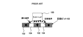
図14に示すように、磁性記録膜を成膜したガラス基板上にレジストを塗布し、レジストに記録ドットパターン、サーボパターンを形成した後、エッチングプロセスにより、磁性記録膜を除去し、レジストパターンを磁性記録膜102に転写する。レジストを除去し、エッチングプロセスで除去された部分に非磁性膜104を埋め込み、最後に平坦化を行い、パターンド媒体100を形成する。以上の方法で作製したパターンド媒体は、ドット102間を、非磁性層104で区切っているため、磁気的にも物理的にも孤立しており高密度記録に適している(例えば、特許文献1,2参照)。
As shown in FIG. 14, after applying a resist on a glass substrate on which a magnetic recording film is formed, forming a recording dot pattern and servo pattern on the resist, the magnetic recording film is removed by an etching process, and the resist pattern is formed. Transfer to the
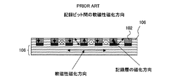
又、図15に示すように、裏打ち層と非磁性層を一体形成する目的で、基板110上に、ポリマーを含んだ軟磁性微粒子をインプリントによりプレス加工し、その後過熱して、軟磁性層106を形成し、その凹部に、下地層及び中間層108と、磁気記録ドット102を形成したパターンド媒体が提案されている(例えば、特許文献3参照)。
Further, as shown in FIG. 15, for the purpose of integrally forming the backing layer and the nonmagnetic layer, soft magnetic fine particles containing a polymer are pressed on the
このパターンド媒体では、磁気記録ドット102の周り及び下部を、軟磁性層106で囲む構造を備える。
磁気記録装置は、継続して記録密度の高密度化が要求されている。このため、パターンド媒体にも、そのドット間隔を、狭くすることが要求される。 Magnetic recording apparatuses are required to continuously increase the recording density. For this reason, the patterned medium is also required to have a narrow dot interval.
図16は、従来技術の問題点の説明図である。このドット間の狭小化が進むと、あるドットへ記録時に、磁気ヘッド(ライトヘッド)110からの記録磁界の漏れ磁界が、隣接ドット102へ影響を与え、その隣接ドット102の磁気情報を消してしまう。いわゆる、サイドイレーズが生じることが問題となる。ドット間の狭小化により、ライトヘッド110の浮上量も小さくなり、サイドイレーズの発生を避けることは、難しい。
FIG. 16 is an explanatory diagram of the problems of the prior art. As the dot narrowing progresses, the recording magnetic field leakage magnetic field from the magnetic head (write head) 110 affects the
一方、第2の従来技術のパターンド媒体では、図17に示すように、ビット間の軟磁性膜と、記録層102の下部の軟磁性膜106は、連続して一体になっており、ビット間の軟磁性層と軟磁性裏打ち層106間の磁気的な結合が生じる。このため、記録再生時に磁気ノイズの発生が懸念される。さらに、パターン形成後、軟磁性微粒子を固めるために熱処理が必要となるため、基板、下地層材料として耐熱性に優れた材料の選定が求められる。
On the other hand, in the patterned medium of the second prior art, as shown in FIG. 17, the soft magnetic film between the bits and the soft
即ち、図16の記録時に動く記録層下部の軟磁性膜106の磁化方向の影響を受け、ビット間の軟磁性膜106の磁化方向も動き易い。又、ビット間の軟磁性膜は、その形状から、磁化方向が垂直に向きやすい。
That is, under the influence of the magnetization direction of the soft
このため、記録ビット間の軟磁性膜の磁化方向は、常に、不安定状態であり、サイドイレーズの低減効果は、期待できない。しかも、記録ドット自体の磁化にも影響を与え、読み出し時のSN(Signal to Noise)比の増大をもたらすおそれがある。 For this reason, the magnetization direction of the soft magnetic film between the recording bits is always in an unstable state, and the effect of reducing the side erase cannot be expected. In addition, the magnetization of the recording dot itself is also affected, and there is a risk of increasing the SN (Signal to Noise) ratio during reading.
従って、本発明の目的は、記録ドット間を狭くしても、サイドイレーズを有効に抑圧するための磁気記録媒体、磁気記録再生装置及び磁気記録媒体の製造方法を提供することにある。 Accordingly, an object of the present invention is to provide a magnetic recording medium, a magnetic recording / reproducing apparatus, and a method of manufacturing a magnetic recording medium for effectively suppressing side erasure even when the gap between recording dots is narrowed.
又、本発明の他の目的は、記録ドット間を狭くしても、サイドイレーズを有効に抑圧し、且つ記録ドットの磁気的な分離性を確保するための磁気記録媒体、磁気記録再生装置及び磁気記録媒体の製造方法を提供することにある。 Another object of the present invention is to provide a magnetic recording medium, a magnetic recording / reproducing apparatus, and a magnetic recording medium for effectively suppressing side erasure and ensuring magnetic separation of recording dots even when the recording dots are narrowed. An object of the present invention is to provide a method for manufacturing a magnetic recording medium.
更に、本発明の他の目的は、記録ドット間を狭くしても、サイドイレーズを有効に抑圧し、高密度記録を実現するための磁気記録媒体、磁気記録再生装置及び磁気記録媒体の製造方法を提供することにある。 Furthermore, another object of the present invention is to provide a magnetic recording medium, a magnetic recording / reproducing apparatus, and a method of manufacturing a magnetic recording medium for effectively suppressing side erasure and realizing high-density recording even when recording dots are narrowed. Is to provide.
この目的の達成のため、本発明の磁気記録媒体は、基板と、前記基板上に設けられた軟磁性裏打ち層と、前記軟磁性裏打ち層上に設けられた非磁性層と、前記非磁性層上に設けられ、硬磁性材料によって形成され、物理的に分離された複数の磁性ドットを有する磁性記録層と、前記磁性記録層の前記磁性ドットの周りを囲むように前記非磁性層上に設けられた軟磁性層とを有する。 In order to achieve this object, a magnetic recording medium of the present invention includes a substrate, a soft magnetic backing layer provided on the substrate, a nonmagnetic layer provided on the soft magnetic backing layer, and the nonmagnetic layer. Provided on the non-magnetic layer so as to surround the magnetic dots of the magnetic recording layer, the magnetic recording layer having a plurality of magnetic dots physically formed and separated by a hard magnetic material. A soft magnetic layer.
又、本発明の磁気記録再生装置は、磁気記録媒体と、前記磁気記録媒体のデータを読み取り且つ書き込む電磁変換素子と、前記電磁変換素子を前記磁気記録媒体の任意の位置に移動するアクチュエータとを有し、前記磁気記録媒体は、基板と、基板上に設けられた軟磁性裏打ち層と、前記軟磁性裏打ち層上に設けられた非磁性層と、前記非磁性層上に設けられ、硬磁性材料によって形成され、物理的に分離された複数の磁性ドットを有する磁性記録層と、前記磁性記録層の前記磁性ドットの周りを囲むように前記非磁性層上に設けられた軟磁性層とを有する。 The magnetic recording / reproducing apparatus of the present invention includes a magnetic recording medium, an electromagnetic conversion element that reads and writes data on the magnetic recording medium, and an actuator that moves the electromagnetic conversion element to an arbitrary position of the magnetic recording medium. The magnetic recording medium includes a substrate, a soft magnetic backing layer provided on the substrate, a nonmagnetic layer provided on the soft magnetic backing layer, and a hard magnetic layer provided on the nonmagnetic layer. A magnetic recording layer formed of a material and having a plurality of physically separated magnetic dots, and a soft magnetic layer provided on the nonmagnetic layer so as to surround the magnetic dots of the magnetic recording layer Have.
又、本発明の磁気記録媒体の製造方法は、基板上に、軟磁性裏打ち層と、非磁性層と、硬磁性材料によって形成された磁気記録層を、成膜する第1の工程と、前記成膜された基板の前記磁気記録層にレジストを塗布し、前記レジストに、物理的に分離された複数の磁性ドットを形成するためのパターンを形成する第2の工程と、前記パターン形成されたレジストを介し、エッチング又はイオン注入のいずれかにより、前記磁性記録層の前記磁性ドットの周りを囲むように前記非磁性層上に軟磁性層を形成する第3の工程とを有する。 The method for producing a magnetic recording medium of the present invention includes a first step of forming a magnetic recording layer formed of a soft magnetic backing layer, a nonmagnetic layer, and a hard magnetic material on a substrate, A second step of applying a resist to the magnetic recording layer of the film-formed substrate and forming a pattern for forming a plurality of physically separated magnetic dots on the resist; And a third step of forming a soft magnetic layer on the nonmagnetic layer so as to surround the magnetic dots of the magnetic recording layer by either etching or ion implantation through a resist.
更に、本発明では、好ましくは、前記軟磁性層の磁化容易軸方向が、前記基板に対して水平であり、前記磁気記録層の磁化容易軸方向が、前記基板に対して垂直である。 In the present invention, it is preferable that the easy axis direction of the soft magnetic layer is horizontal to the substrate, and the easy axis direction of the magnetic recording layer is perpendicular to the substrate.
更に、本発明では、好ましくは、前記磁性ドットと前記軟磁性層との境界に、非磁性部材を設ける。 Furthermore, in the present invention, preferably, a nonmagnetic member is provided at the boundary between the magnetic dots and the soft magnetic layer.
更に、本発明では、好ましくは、前記軟磁性層の保磁力が、前記磁気記録層の保持力より小さい。 Furthermore, in the present invention, preferably, the coercive force of the soft magnetic layer is smaller than the coercive force of the magnetic recording layer.
更に、本発明では、好ましくは、前記磁性記録層は、垂直磁化膜で構成された。 Furthermore, in the present invention, preferably, the magnetic recording layer is formed of a perpendicular magnetization film.
更に、本発明では、好ましくは、前記磁気記録媒体は、磁気ディスクで構成され、前記電磁変換素子は、前記磁気ディスクのデータを読み取る読み取り素子と、前記磁気ディスクにデータを書き込む書込み素子とで構成された。 In the present invention, it is preferable that the magnetic recording medium is composed of a magnetic disk, and the electromagnetic conversion element is composed of a reading element for reading data on the magnetic disk and a writing element for writing data on the magnetic disk. It was done.
更に、本発明では、好ましくは、前記第3の工程は、前記パターン形成されたレジストを介し、前記磁気記録層をエッチングする工程と、前記レジストを剥離する工程と、前記磁性記録層の前記磁性ドットの周りを囲むように前記非磁性層上に軟磁性層を形成する工程とを有する。 Furthermore, in the present invention, preferably, the third step includes a step of etching the magnetic recording layer through the patterned resist, a step of peeling the resist, and the magnetic recording layer. Forming a soft magnetic layer on the nonmagnetic layer so as to surround the dots.
更に、本発明では、好ましくは、前記第3の工程は、前記パターン形成されたレジストを介し、前記磁気記録層に、非磁性材料原子をイオン注入して、軟磁性に改質する工程と、前記レジストを剥離する工程とを有する。 Further, in the present invention, preferably, the third step is a step of ion-implanting nonmagnetic material atoms into the magnetic recording layer through the patterned resist to modify the magnetic recording layer, Removing the resist.
更に、本発明では、好ましくは、前記軟磁性層を形成する工程は、前記エッチングされた磁性記録層に対し、非磁性材料と前記軟磁性材料とを、前記磁性記録層の前記磁性ドットの周りを囲むように前記非磁性層上に形成する工程を有する。 Furthermore, in the present invention, it is preferable that the step of forming the soft magnetic layer includes the step of forming a nonmagnetic material and the soft magnetic material around the magnetic dots of the magnetic recording layer with respect to the etched magnetic recording layer. Forming on the nonmagnetic layer so as to surround the substrate.
更に、本発明では、好ましくは、前記磁気記録層をエッチングする工程は、前記レジストを介し、イオンミリング法により前記硬磁性材料及び下部の非磁性材料を削り、前記下部非磁性材料のミリング時に生じる前記磁気記録層の形成パターン側壁への非磁性材料の再付着により、前記非磁性材料を前記磁性ドットの周囲に形成する工程を有する。 Furthermore, in the present invention, it is preferable that the step of etching the magnetic recording layer occurs when the lower nonmagnetic material is milled by scraping the hard magnetic material and the lower nonmagnetic material by the ion milling method through the resist. Forming a non-magnetic material around the magnetic dots by reattaching the non-magnetic material to the side wall of the magnetic recording layer.
軟磁性下地層上に、非磁性層を介し、磁性ドットと軟磁性層を設け、軟磁性層で、磁性ドットを分離するため、磁性ドットへの記録時の漏れ磁束を、軟磁性層が吸収し、サイドイレーズを抑圧でき、且つ軟磁性下地層と、軟磁性層とが、分離しているため、記録再生特性への影響を防止できる。 A magnetic dot and a soft magnetic layer are provided on the soft magnetic underlayer via a nonmagnetic layer, and the magnetic dot is separated by the soft magnetic layer. Therefore, the soft magnetic layer absorbs the magnetic flux leakage during recording on the magnetic dot. In addition, side erasure can be suppressed and the soft magnetic underlayer and the soft magnetic layer are separated from each other, so that the influence on the recording / reproducing characteristics can be prevented.
以下、本発明の実施の形態を、磁気記録再生装置の構成、磁気記録媒体の第1の実施の形態、磁気記録媒体の第2の実施の形態、磁気記録媒体の製造方法の第1の実施の形態、磁気記録媒体の製造方法の第2の実施の形態、磁気記録媒体の製造方法の第3の実施の形態、磁気記録媒体の製造方法の第4の実施の形態、他の実施の形態の順で説明するが、本発明は、この実施の形態に限られない。 Hereinafter, embodiments of the present invention will be described with reference to a configuration of a magnetic recording / reproducing apparatus, a first embodiment of a magnetic recording medium, a second embodiment of a magnetic recording medium, and a first embodiment of a method for manufacturing a magnetic recording medium. Embodiment, Second Embodiment of Magnetic Recording Medium Manufacturing Method, Third Embodiment of Magnetic Recording Medium Manufacturing Method, Fourth Embodiment of Magnetic Recording Medium Manufacturing Method, Other Embodiments However, the present invention is not limited to this embodiment.
(磁気記録再生装置)
図1は、本発明の磁気記録再生装置の一実施の形態の外観図である。図1は、磁気記録再生装置として、磁気ディスク装置(ハードディスクドライブ)を例に示す。
(Magnetic recording / reproducing device)
FIG. 1 is an external view of an embodiment of a magnetic recording / reproducing apparatus of the present invention. FIG. 1 shows a magnetic disk device (hard disk drive) as an example of a magnetic recording / reproducing device.
図1に示すように、ディスクエンクロージャ(DEという)1では、磁気記録媒体である磁気ディスク3が、スピンドルモータ4の回転軸に設けられている。スピンドルモータ4は、磁気ディスク3を回転する。アクチュエータ(VCMという)5は、アーム(ヘッドアクチュエータという)52、サスペンションの先端に磁気ヘッド53を備え、磁気ヘッド53を磁気ディスク3の半径方向に移動する。
As shown in FIG. 1, in a disk enclosure (referred to as DE) 1, a
アクチュエータ5は、回転軸を中心に回転するボイスコイルモータ(VCM)で構成される。図1では、磁気ディスク装置に、1枚の磁気ディスク3が搭載され、2つの磁気ヘッド53が、同一のアクチュエータ5で同時に駆動される。
The
磁気ヘッド53は、リード素子と、ライト素子とからなる。磁気ヘッド53は、スライダに、磁気抵抗(MR)素子を含むリード素子を積層し、その上にライトコイルを含むライト素子を積層して、構成される。
The
磁気ディスク3の外側には、磁気ヘッド2を磁気ディスク3から退避し、パーキングするためのランプ機構54が設けられる。
A
又、図1の下部には、プリント回路アッセンブリ(制御回路部)が設けられ、プリント回路アッセンブリには、ハードディスクコントローラ(HDC)、マイクロコントローラ(MCU)、リード/ライトチャネル回路(RDC)、サーボコントロール回路、データバッファ(RAM)、ROM(リードオンリーメモリ)が設けられる。この磁気ディスク3として、以下で説明するパターンド媒体が用いられ、磁気ヘッド53は、垂直記録ヘッドで構成される。
In addition, a printed circuit assembly (control circuit unit) is provided at the bottom of FIG. 1, and the printed circuit assembly includes a hard disk controller (HDC), a microcontroller (MCU), a read / write channel circuit (RDC), and a servo control. A circuit, a data buffer (RAM), and a ROM (read only memory) are provided. As the
(磁気記録媒体の第1の実施の形態)
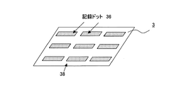
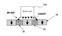
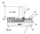
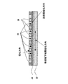
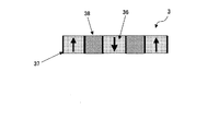
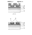
図2は、本発明の磁気記録媒体の第1の実施の形態の断面図、図3は、図2の斜視図、図4は、図2の構成によるサイドイレーズ抑圧効果の説明図、図5は、垂直記録の磁気フラックスの説明図、図6は、図2の構成の磁化方向の説明図である。
(First Embodiment of Magnetic Recording Medium)
2 is a cross-sectional view of the first embodiment of the magnetic recording medium of the present invention, FIG. 3 is a perspective view of FIG. 2, FIG. 4 is an explanatory view of the side erase suppression effect by the configuration of FIG. FIG. 6 is an explanatory diagram of the magnetic flux of perpendicular recording, and FIG.
図2に示すように、磁気記録媒体3は、基板30上に、軟磁性裏打ち層32、非磁性中間層34、磁気記録層(硬磁性材料)36を設けた多層構造である。そして、図3にも示すように、磁気記録層36は、軟磁性膜38で区切られ、記録ドットを形成する。軟磁性膜38の保磁力は、磁気記録層36よりも少なく、約100Oe(エルステッド)程度であり、且つ磁化方向は、基板面に対して水平(面内)方向を持つことが望ましい。
As shown in FIG. 2, the
軟磁性層38の形成方法としては、上記した多層構造の膜を、パターン形状に、一層又は二層以上をエッチング法などにより除去した後、スパッタ法などにより、除去した部分に、軟磁性材料38を成膜する。その後、余分な軟磁性層膜38を除去し、最後に、表面平坦化を行い、形成する。
As a method for forming the soft
基板30としては、ガラス基板が用いられ、ガラス基板に密着性向上のため、ガラス基板30上に、下地層としてクロム合金膜を設けることが望ましい。軟磁性裏打ち層32としては、Co合金/Ru/Co合金からなるAPS−SUL構造(Anti-Parallel-Structure magnetic Soft Under Layer)を持つ多層膜を用いることが望ましい。又、中間層34としてRu層を、磁気記録層36として、Co合金垂直磁化膜を用いる。
As the
軟磁性材料38としては、NiFe合金やCoNiFe合金などを用いる。このときに必要であれば、スパッタ成膜時に磁場を印加する)。
As the soft
このような構成によれば、図4に示すように、ドット間隔を狭めた場合でも、磁気ヘッド(ライトヘッド)53aからの漏れ磁界が,ビット36間の軟磁性層38に吸い込まれ,隣接ドット36への漏れ磁界の影響を防ぐことができる。このため、サイドイレーズ問題が解決される。
According to such a configuration, as shown in FIG. 4, even when the dot interval is narrowed, the leakage magnetic field from the magnetic head (write head) 53a is sucked into the soft
又、軟磁性層38と軟磁性裏打ち層32も分離されており、高密度記録用パターンド媒体構造として適している。更に、熱処理も不要であるため、膜構造、基板及び膜材料の選択性の自由度が高い。
Further, the soft
図5に示すように、垂直磁気記録方式では、ライトヘッド23の磁極23−1とライトヘッド23のシールド23−2間の磁界フラックスの流れは、基板3の磁気記録層38、下地層を介し、軟磁性裏打ち層32を通る。ここで、磁気記録層38への垂直方向の磁気フラックスは、軟磁性裏打ち層32で水平方向になり、シールド23−3へ、垂直方向に分散される。
As shown in FIG. 5, in the perpendicular magnetic recording system, the magnetic flux flux between the magnetic pole 23-1 of the
図6に示すように、軟磁性層38と軟磁性裏打ち層32が、非磁性下地層34で分離されているため、記録時に動く軟磁性裏打ち層32の磁化方向が、軟磁性層38の磁化に影響しない。このため、ビット間の軟磁性層38の磁化方向は、常に安定しており、軟磁性層38で、磁気記録層36を分離しても、記録特性に影響を与えず、サイドイレーズを抑圧できる。
As shown in FIG. 6, since the soft
しかも、ビット間の軟磁性層38の磁化方向は、その形状から、垂直にも向きやすいが、スパッタ法等で形成された磁気特性(異方性)が優れているため、面内方向を向いている。このため、軟磁性層38の磁化が、磁気記録層36の磁化方向に影響しない。
In addition, the magnetization direction of the soft
このように、記録ドット36間に軟磁性層38を設け、記録時に発生する記録磁界の隣接ドットへの漏れ磁界を軟磁性層で吸収し、サイドイレーズを抑制できる。しかも、軟磁性層38と軟磁性裏打ち層32が、非磁性下地層34で分離されているため、より記録・再生エラーの少ない高信頼のパターンド媒体の提供が可能となる。また、軟磁性層を介すことにより、ドット間をさらに狭めることを可能とし、高記録密度で信頼性の高いパターンド媒体を提供できる。
As described above, the soft
(磁気記録媒体の第2の実施の形態)
図7は、本発明の磁気記録媒体の第2の実施の形態の斜視図、図8は、図7の断面図であり、図2及び図6の記録層と軟磁性層の部分のみを示す。
(Second Embodiment of Magnetic Recording Medium)
FIG. 7 is a perspective view of the second embodiment of the magnetic recording medium of the present invention, and FIG. 8 is a cross-sectional view of FIG. 7, showing only the recording layer and soft magnetic layer portions of FIGS. .
図7及び図8に示すように、上記した図2及び図6の構成に加えて、軟磁性層38と磁気記録層36の間に非磁性層37を挟む構成とする。
As shown in FIGS. 7 and 8, in addition to the configuration of FIGS. 2 and 6, the
即ち、図2及び図6に示したように、基板30上に、軟磁性裏打ち層32、非磁性中間層34、磁気記録層(硬磁性材料)36を設けた多層構造の磁気記録媒体に、磁気記録層36を、軟磁性膜38で区切り、記録ドットを形成する。この構成において、軟磁性層38と磁気記録層36の間に非磁性層37を挟む構成とする。
That is, as shown in FIGS. 2 and 6, a magnetic recording medium having a multilayer structure in which a soft
この構成により、軟磁性層38から磁気記録層36への磁気的な結合を低減することが可能となり、記録磁界分布を急峻にすることができる。このため、より、高密度記録に適している。
With this configuration, the magnetic coupling from the soft
(磁気記録媒体の製造方法の第1の実施の形態)
図9は、本発明の磁気記録媒体の製造方法の第1の実施の形態の工程図である。図9は、図2、図3で説明した第1の実施の形態の磁気記録媒体を製造する方法を示す。
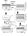
(First Embodiment of Manufacturing Method of Magnetic Recording Medium)
FIG. 9 is a process diagram of the first embodiment of the method of manufacturing the magnetic recording medium of the present invention. FIG. 9 shows a method of manufacturing the magnetic recording medium according to the first embodiment described with reference to FIGS.
(a)スパッタ成膜工程:2.5インチHDD(ハードディスクドライブ)用ガラス基板30上に、スパッタ法を用いて多層膜の成膜を行う。多層膜の構成として、基板30側から下地層33、軟磁性裏打ち層32、中間層34、磁気記録層36の順番で、成膜を行う。尚、各層の構成は単層とは限らず、多層膜によって構成されても良い。
(A) Sputter deposition process: A multilayer film is deposited on a
本実施例では、下地層33としてクロム合金膜を、軟磁性裏打ち層32としてCo合金/Ru/Co合金からなるAPS−SUL構造(Anti-Parallel-Structure magnetic Soft Under Layer)を持つ多層膜を、中間層34としてRu層を、磁気記録層36としてCo合金垂直磁化膜を用いた。
In this embodiment, a chromium alloy film is used as the
(b)、(c)UVインプリント工程:上記スパッタ成膜されたサンプルの磁気記録層36上に、レジスト42(紫外線硬化樹脂等)を塗布し、電子線描画装置などにより、データ領域及びサーボパターンを描画され、記録ドットパターンを凸部として形成されたガラスモールド40を使用し、UV(紫外線)インプリント法を行う。即ち、上記スパッタ成膜されたサンプル上に塗布されたレジスト(UV硬化樹脂など)42上に、モールド40を押し当て、紫外線を照射して、レジスト42へのパターンの転写を行う。
(B), (c) UV imprinting process: A resist 42 (ultraviolet curable resin or the like) is applied on the
レジスト42へのモールドパターン転写法としては、UVインプリント法の他に、レジストを熱で軟化させた後、モールド40を押し付け、パターンを転写する熱インプリント法の使用も可能である。また、上記スパッタ成膜後のサンプルに、レジスト42を塗布し、電子線描画装置で直接パターンを描画する方法もある。この方法は、描画に時間が掛かり、量産には、好ましくない。
As a mold pattern transfer method to the resist 42, besides the UV imprint method, it is possible to use a thermal imprint method in which the resist 40 is softened by heat and then the
(d)イオンミリング工程:エッチング法として、イオンミリング法を用いて、レジスト42をマスクとして、磁気記録層36のエッチングを行い、レジスト42のパターンにより、磁気記録層36の凹凸を形成する。エッチング方法としては、イオンミリング法のほかに、リアクティブエッチング方法なども適用できる。また、エッチングは、必要であれば、磁気記録層36の途中、または磁気記録層36の下部の層までエッチングすることも可能である。
(D) Ion milling process: As an etching method, the
(e)レジスト剥離工程:レジスト42を溶剤などで除去することにより、磁気記録層36にドットパターン(凹凸)を形成する。
(E) Resist stripping step: A dot pattern (unevenness) is formed on the
(f)軟磁性材料成膜工程:スパッタ成膜法などにより、軟磁性材料38を、上記サンプルの(磁性記録層36)上に成膜を行い、磁性記録層36の凹部に、軟磁性材料38を埋め込む。軟磁性材料38としては、NiFe合金やCoNiF合金などを用いる。このときに必要であれば、スパッタ成膜時に磁場を印加する。
(F) Soft magnetic material film forming step: The soft
(g)表面平坦化工程:表面に溢れた軟磁性材料38を除去するため、平坦化処理を行う。平坦化方法として、CMP法(Chemical Mechanical Polishing)や機械研磨法、低角ミリング法、ガスクラスターイオンビーム法などを適用できる。研磨後のサンプル表面は、磁気ヘッド53の浮上が可能な平坦性が必要とされる。本実施例では、原子間力顕微鏡(AFM; Atomic Force Microscopy : Veeco製)の測定で、中心線平均粗さ(Ra)<1nmとした。
(G) Surface flattening step: A flattening process is performed to remove the soft
(h)保護膜形成及び潤滑油塗布工程:保護膜44としてスパッタ成膜法により、カーボンを成膜した後、潤滑剤46を浸漬法で塗布する。
(H) Protective film formation and lubricating oil application process: After forming carbon as the
このようにして、図2、図3で説明した第1の実施の形態の磁気記録媒体を、熱処理工程なしに、製造できる。 In this way, the magnetic recording medium of the first embodiment described with reference to FIGS. 2 and 3 can be manufactured without a heat treatment step.
(磁気記録媒体の製造方法の第2の実施の形態)
図10は、本発明の磁気記録媒体の製造方法の第2の実施の形態の工程図である。図10は、図7、図8で説明した第2の実施の形態の磁気記録媒体を製造する方法を示す。
(Second Embodiment of Manufacturing Method of Magnetic Recording Medium)
FIG. 10 is a process diagram of the second embodiment of the method of manufacturing the magnetic recording medium of the present invention. FIG. 10 shows a method of manufacturing the magnetic recording medium according to the second embodiment described with reference to FIGS.
以下、図9も参照して、説明する。図7及び図8の磁気記録層36と軟磁性層38間に、非磁性層37を挟む構造を作製する方法として、図9の軟磁性材料成膜工程(f)を変形する。
Hereinafter, a description will be given with reference to FIG. As a method for producing a structure in which the
即ち、成膜工程(f)のスパッタ法による軟磁性材料38の埋め込み時に、軟磁性材料38の代わりに非磁性材料37/軟磁性材料38の二層構造膜を成膜する方法である。この場合は、成膜後のプロセスは、図9の表面平坦化工程(g)、保護膜形成及び潤滑油塗布工程(h)と同じ工程を行う。この時、軟磁性層36の下部には、成膜した非磁性層38が残り、図7、図8で説明した第2の実施の形態の磁気記録媒体を、熱処理工程なしに、製造できる。
In other words, when the soft
(磁気記録媒体の製造方法の第3の実施の形態)
図11は、本発明の磁気記録媒体の製造方法の第3の実施の形態の工程図である。図11は、図7、図8で説明した第2の実施の形態の磁気記録媒体を製造する方法を示す。
(Third embodiment of manufacturing method of magnetic recording medium)
FIG. 11 is a process diagram of the third embodiment of the method for manufacturing a magnetic recording medium of the present invention. FIG. 11 shows a method of manufacturing the magnetic recording medium according to the second embodiment described with reference to FIGS.
以下、図9も参照して、説明する。図7及び図8の磁気記録層36と軟磁性層38間に、非磁性層37を挟む構造を作製する方法として、図9のイオンミリング工程(d)を変形する。即ち、イオンミリング装置によるパターンエッチング時に生じるエッチングされた材料の再付着を用いる方法を利用する。
Hereinafter, a description will be given with reference to FIG. As a method for producing a structure in which the
イオンミリング装置でエッチングを行う場合、エッチングされた材料が、エッチングで形成されたパターンの側壁に付着することが知れられている。例えば、特開2005−267736号公報では、レジストに磁性材料を付着させて突起を形成し、平坦化工程での平坦性を制御する方法に使われている。 When etching is performed with an ion milling apparatus, it is known that the etched material adheres to the side wall of the pattern formed by the etching. For example, Japanese Patent Application Laid-Open No. 2005-267636 uses a method of controlling the flatness in the flattening step by forming a protrusion by attaching a magnetic material to a resist.
本実施の形態では、図11に示す例は、磁気記録層36の下部層に、非磁性層39を設け、前述のミリング工程を実行する。このミリング工程において、磁気記録層36をミリングする時には、レジスト42の側面に、エッチングされた磁気記録層36が付着する。更に、磁気記録層36のミリング後、非磁性層39にイオンミリングを行い、上部の磁気記録層36の壁面に、非磁性材料39を付着させる。
In the present embodiment, in the example shown in FIG. 11, the
その後、図9のレジスト剥離工程(e)を行い、軟磁性材料充填工程(f)で、軟磁性材料38を、スパッタ法などにより成膜する。成膜後のプロセスは、図9の表面平坦化工程(g)、保護膜形成及び潤滑油塗布工程(h)と同じ工程を行う。
Thereafter, the resist stripping step (e) of FIG. 9 is performed, and the soft
(磁気記録媒体の製造方法の第4の実施の形態)
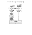
図12は、本発明の磁気記録媒体の製造方法の第4の実施の形態の工程図、図13は、エッチング法とイオン注入法との工程比較図である。図12は、図2、図3で説明した第1の実施の形態の磁気記録媒体を製造する方法を示す。
(Fourth Embodiment of Manufacturing Method of Magnetic Recording Medium)
FIG. 12 is a process diagram of the fourth embodiment of the method for manufacturing a magnetic recording medium of the present invention, and FIG. 13 is a process comparison diagram between the etching method and the ion implantation method. FIG. 12 shows a method of manufacturing the magnetic recording medium according to the first embodiment described with reference to FIGS.
図12は、本発明による構造の軟磁性層を形成する方法として、イオン注入法を用いる方法である。イオン注入法は、例えば、特開2006−286085号公報では、磁性材料イオンを注入し、部分的に硬磁性化し、磁気パターンを形成する例を開示している。 FIG. 12 shows a method using an ion implantation method as a method of forming a soft magnetic layer having a structure according to the present invention. For example, Japanese Patent Application Laid-Open No. 2006-286085 discloses an ion implantation method in which magnetic material ions are implanted, partially hardened, and a magnetic pattern is formed.
一方、本実施の形態の場合は、硬磁性材料の軟磁性化を目的としており、注入するイオンとしてアルゴン、酸素、窒素、ボロン、リンなどの非磁性材料を用いる。イオン注入による硬磁性材料(磁気記録材料)への不純物の添加や、構造の破壊効果などにより、軟磁磁気特性に改質することが可能である。 On the other hand, in the case of this embodiment, the purpose is to soften the hard magnetic material, and nonmagnetic materials such as argon, oxygen, nitrogen, boron, and phosphorus are used as ions to be implanted. It is possible to improve the soft magnetic properties by adding impurities to the hard magnetic material (magnetic recording material) by ion implantation or by destroying the structure.
また、図13に示すように、イオン注入法は、エッチング工程がないため、溝への軟磁性材料の充填及び平坦化工程(図9の(f)、(g)、(h))が不要である。このため、製造装置や工程数が、上記エッチングによるパターン形成より少なく、低製造コストが可能である。 Further, as shown in FIG. 13, since the ion implantation method does not have an etching process, the soft magnetic material filling and planarization processes ((f), (g), and (h) in FIG. 9) are unnecessary. It is. For this reason, the manufacturing apparatus and the number of processes are smaller than the pattern formation by the etching, and a low manufacturing cost is possible.
図12により詳細に説明する。 This will be described in detail with reference to FIG.
(a)スパッタ成膜工程:2.5インチHDD(ハードディスクドライブ)用ガラス基板30上に、スパッタ法を用いて多層膜の成膜を行う。多層膜の構成として、基板30側から下地層33、軟磁性裏打ち層32、中間層34、磁気記録層36、保護層44の順番で、成膜を行う。尚、各層の構成は単層とは限らず、多層膜によって構成されても良い。
(A) Sputter deposition process: A multilayer film is deposited on a
本実施例では、下地層33としてクロム合金膜を、軟磁性裏打ち層32としてCo合金/Ru/Co合金からなるAPS−SUL構造(Anti-Parallel-Structure magnetic Soft Under Layer)を持つ多層膜を、中間層34としてRu層を、磁気記録層36としてCo合金垂直磁化膜を用いた。
In this embodiment, a chromium alloy film is used as the
(b)、(c)UVインプリント工程:上記スパッタ成膜されたサンプルの磁気記録層36上に、レジスト42(紫外線硬化樹脂等)を塗布し、電子線描画装置などにより、データ領域及びサーボパターンを描画され、記録ドットパターンを凸部として形成されたガラスモールド40を使用し、UV(紫外線)インプリント法を行う。即ち、上記スパッタ成膜されたサンプル上に塗布されたレジスト(UV硬化樹脂など)42上に、モールド40を押し当て、紫外線を照射して、レジスト42へのパターンの転写を行う。
(B), (c) UV imprinting process: A resist 42 (ultraviolet curable resin or the like) is applied on the
レジスト42へのモールドパターン転写法としては、UVインプリント法の他に、レジストを熱で軟化させた後、モールド40を押し付け、パターンを転写する熱インプリント法の使用も可能である。また、上記スパッタ成膜後のサンプルに、レジスト42を塗布し、電子線描画装置で直接パターンを描画する方法もある。この方法は、描画に時間が掛かり、量産には、好ましくない。
As a mold pattern transfer method to the resist 42, besides the UV imprint method, it is possible to use a thermal imprint method in which the resist 40 is softened by heat and then the
(d)イオン注入工程:イオン注入法により、磁気記録層36のレジスト42が除去された部分に、イオン(アルゴン、酸素、窒素、ボロン、リンなどの非磁性材料)の注入を行い、磁気記録層(硬磁性層)36を、軟磁性層38に変化させる。
(D) Ion implantation step: Ions (nonmagnetic materials such as argon, oxygen, nitrogen, boron, phosphorus) are implanted into the portion of the
(e)レジスト剥離工程:レジスト42を溶剤などで除去した後、浸漬法により、潤滑剤46の塗布を行う。
(E) Resist stripping step: After removing the resist 42 with a solvent or the like, the
このように、イオン注入法は、エッチング工程がないため、製造装置や工程数が、上記エッチングによるパターン形成より少なく、低製造コストが可能である。 As described above, since the ion implantation method does not include an etching process, the number of manufacturing apparatuses and the number of processes is smaller than that of pattern formation by the etching, and a low manufacturing cost is possible.
(他の実施の形態)
前述の実施の形態では、1枚の磁気ディスクを搭載した磁気ディスク装置で説明したが、2枚以上の磁気ディスクを搭載した装置にも適用できる。磁気記録媒体の形態も、ディスク形状に限らず、他の磁気記録媒体に適用でき、磁気ヘッドの形態は、図5のものに限らず、他の分離型磁気ヘッドの形態にも適用できる。
(Other embodiments)
In the above-described embodiment, the magnetic disk device having one magnetic disk is described. However, the present invention can be applied to an apparatus having two or more magnetic disks. The form of the magnetic recording medium is not limited to the disk shape but can be applied to other magnetic recording media, and the form of the magnetic head is not limited to that of FIG.
尚、本発明は、以下に付記する発明を包含する。 In addition, this invention includes the invention attached to the following.
(付記1)基板と、基板上に設けられた軟磁性裏打ち層と、前記軟磁性裏打ち層上に設けられた非磁性層と、前記非磁性層上に設けられ、硬磁性材料によって形成され、物理的に分離された複数の磁性ドットを有する磁性記録層と、前記磁性記録層の前記磁性ドットの周りを囲むように前記非磁性層上に設けられた軟磁性層とを有することを特徴とする磁気記録媒体。 (Appendix 1) A substrate, a soft magnetic backing layer provided on the substrate, a nonmagnetic layer provided on the soft magnetic backing layer, a nonmagnetic layer provided on the nonmagnetic layer, and formed of a hard magnetic material, A magnetic recording layer having a plurality of magnetic dots physically separated; and a soft magnetic layer provided on the nonmagnetic layer so as to surround the magnetic dots of the magnetic recording layer. Magnetic recording media.
(付記2)前記軟磁性層の磁化容易軸方向が、前記基板に対して水平であり、前記磁気記録層の磁化容易軸方向が、前記基板に対して垂直であることを特徴とする請求項1記載の磁気記録媒体。 (Appendix 2) The easy axis of magnetization of the soft magnetic layer is horizontal to the substrate, and the easy axis of magnetization of the magnetic recording layer is perpendicular to the substrate. The magnetic recording medium according to 1.
(付記3)前記上記の磁性ドットと前記軟磁性層との境界に、非磁性部材を設けることを特徴とする請求項1記載の磁気記録媒体。
(Supplementary note 3) The magnetic recording medium according to
(付記4)前記軟磁性層の保磁力が、前記磁気記録層の保持力より小さいことを特徴とする請求項1記載の磁気記録媒体。
(Supplementary note 4) The magnetic recording medium according to
(付記5)前記磁性記録層は、垂直磁化膜で構成されたことを特徴とする請求項1記載の磁気記録媒体。
(Supplementary note 5) The magnetic recording medium according to
(付記6)磁気記録媒体と、前記磁気記録媒体のデータを読み取り且つ書き込む電磁変換素子と、前記電磁変換素子を前記磁気記録媒体の任意の位置に移動するアクチュエータとを有し、前記磁気記録媒体は、基板と、基板上に設けられた軟磁性裏打ち層と、前記軟磁性裏打ち層上に設けられた非磁性層と、前記非磁性層上に設けられ、硬磁性材料によって形成され、物理的に分離された複数の磁性ドットを有する磁性記録層と、前記磁性記録層の前記磁性ドットの周りを囲むように前記非磁性層上に設けられた軟磁性層とを有することを特徴とする磁気記録再生装置。 (Additional remark 6) It has a magnetic recording medium, the electromagnetic transducer which reads and writes the data of the said magnetic recording medium, and the actuator which moves the said electromagnetic transducer to the arbitrary positions of the said magnetic recording medium, The said magnetic recording medium Is a substrate, a soft magnetic backing layer provided on the substrate, a nonmagnetic layer provided on the soft magnetic backing layer, and a hard magnetic material provided on the nonmagnetic layer, A magnetic recording layer having a plurality of magnetic dots separated from each other, and a soft magnetic layer provided on the nonmagnetic layer so as to surround the magnetic dots of the magnetic recording layer. Recording / playback device.
(付記7)前記軟磁性層の磁化容易軸方向が、前記基板に対して水平であり、前記磁気記録層の磁化容易軸方向が、前記基板に対して垂直であることを特徴とする請求項6記載の磁気記録再生装置。 (Supplementary note 7) The easy magnetization axis direction of the soft magnetic layer is horizontal to the substrate, and the easy magnetization axis direction of the magnetic recording layer is perpendicular to the substrate. 6. The magnetic recording / reproducing apparatus according to 6.
(付記8)前記上記の磁性ドットと前記軟磁性層との境界に、非磁性部材を設けることを特徴とする請求項6記載の磁気記録再生装置。 (Supplementary note 8) The magnetic recording / reproducing apparatus according to claim 6, wherein a nonmagnetic member is provided at a boundary between the magnetic dot and the soft magnetic layer.
(付記9)前記軟磁性層の保磁力が、前記磁気記録層の保持力より小さいことを特徴とする請求項6記載の磁気記録再生装置。 (Supplementary note 9) The magnetic recording / reproducing apparatus according to claim 6, wherein the coercive force of the soft magnetic layer is smaller than the coercive force of the magnetic recording layer.
(付記10)前記磁性記録層は、垂直磁化膜で構成されたことを特徴とする請求項6記載の磁気記録再生装置。 (Supplementary note 10) The magnetic recording / reproducing apparatus according to claim 6, wherein the magnetic recording layer comprises a perpendicular magnetization film.
(付記11)前記磁気記録媒体は、磁気ディスクで構成され、前記電磁変換素子は、前記磁気ディスクのデータを読み取る読み取り素子と、前記磁気ディスクにデータを書き込む書込み素子とで構成されたことを特徴とする付記6の磁気記録再生装置。 (Supplementary Note 11) The magnetic recording medium is configured by a magnetic disk, and the electromagnetic conversion element is configured by a reading element for reading data on the magnetic disk and a writing element for writing data on the magnetic disk. The magnetic recording / reproducing apparatus according to appendix 6.
(付記12)基板上に、軟磁性裏打ち層と、非磁性層と、硬磁性材料によって形成された磁気記録層を、成膜する第1の工程と、前記成膜された基板の前記磁気記録層にレジストを塗布し、前記レジストに、物理的に分離された複数の磁性ドットを形成するためのパターンを形成する第2の工程と、前記パターン形成されたレジストを介し、エッチング又はイオン注入のいずれかにより、前記磁性記録層の前記磁性ドットの周りを囲むように前記非磁性層上に軟磁性層を形成する第3の工程とを有することを特徴とする磁気記録媒体の製造方法。 (Supplementary note 12) A first step of forming a magnetic recording layer formed of a soft magnetic backing layer, a nonmagnetic layer, and a hard magnetic material on a substrate, and the magnetic recording of the formed substrate Applying a resist to the layer and forming a pattern for forming a plurality of physically separated magnetic dots on the resist; and etching or ion implantation through the patterned resist. And a third step of forming a soft magnetic layer on the nonmagnetic layer so as to surround the magnetic dots of the magnetic recording layer.
(付記13)前記第3の工程は、前記パターン形成されたレジストを介し、前記磁気記録層をエッチングする工程と、前記レジストを剥離する工程と、前記磁性記録層の前記磁性ドットの周りを囲むように前記非磁性層上に軟磁性層を形成する工程とを有することを特徴とする付記12の磁気記録媒体の製造方法。 (Supplementary Note 13) The third step surrounds the magnetic recording layer, the step of etching the magnetic recording layer through the patterned resist, the step of peeling the resist, and the magnetic recording layer. And a step of forming a soft magnetic layer on the nonmagnetic layer as described above.
(付記14)前記第3の工程は、前記パターン形成されたレジストを介し、前記磁気記録層に、非磁性材料原子をイオン注入して、軟磁性に改質する工程と、前記レジストを剥離する工程とを有することを特徴とする付記12の磁気記録媒体の製造方法。 (Supplementary Note 14) The third step includes a step of ion-implanting nonmagnetic material atoms into the magnetic recording layer through the patterned resist to modify the magnetic recording layer, and removing the resist. The method of manufacturing a magnetic recording medium according to appendix 12, characterized by comprising the steps of:
(付記15)前記軟磁性層を形成する工程は、前記エッチングされた磁性記録層に対し、非磁性材料と前記軟磁性材料とを、前記磁性記録層の前記磁性ドットの周りを囲むように前記非磁性層上に形成する工程を有することを特徴とする付記13の磁気記録媒体の製造方法。 (Supplementary Note 15) In the step of forming the soft magnetic layer, the nonmagnetic material and the soft magnetic material are surrounded by the etched magnetic recording layer so as to surround the magnetic dots of the magnetic recording layer. The method for producing a magnetic recording medium according to appendix 13, wherein the method comprises a step of forming on a nonmagnetic layer.
(付記16)前記磁気記録層をエッチングする工程は、前記レジストを介し、イオンミリング法により前記硬磁性材料及び下部の非磁性材料を削り、前記下部非磁性材料のミリング時に生じる前記磁気記録層の形成パターン側壁への非磁性材料の再付着により、前記非磁性材料を前記磁性ドットの周囲に形成する工程を有することを特徴とする請求項13記載の磁気記録媒体の製造方法。 (Supplementary Note 16) The step of etching the magnetic recording layer includes the step of etching the hard magnetic material and the lower nonmagnetic material by an ion milling method through the resist, and generating the magnetic recording layer when the lower nonmagnetic material is milled. 14. The method of manufacturing a magnetic recording medium according to claim 13, further comprising the step of forming the nonmagnetic material around the magnetic dots by reattaching the nonmagnetic material to the side wall of the formation pattern.
軟磁性下地層上に、非磁性層を介し、磁性ドットと軟磁性層を設け、軟磁性層で、磁性ドットを分離するため、磁性ドットへの記録時の漏れ磁束を、軟磁性層が吸収し、サイドイレーズを抑圧でき、且つ軟磁性下地層と、軟磁性層とが、分離しているため、記録再生特性への影響を防止できる。 A magnetic dot and a soft magnetic layer are provided on the soft magnetic underlayer via a nonmagnetic layer, and the magnetic dot is separated by the soft magnetic layer. Therefore, the soft magnetic layer absorbs the magnetic flux leakage during recording on the magnetic dot. In addition, side erasure can be suppressed and the soft magnetic underlayer and the soft magnetic layer are separated from each other, so that the influence on the recording / reproducing characteristics can be prevented.
1 磁気ディスクエンクロージャ(DE)
3 磁気ディスク
4 スピンドルモータ
5 アクチュエータ(VCM)
52 アーム
53 磁気ヘッド(電磁変換素子)
30 ガラス基板
32 軟磁性下地層
33 下地層
34 下地層(非磁性層)
36 磁性記録層
38 軟磁性層
39 非磁性層
1 Magnetic disk enclosure (DE)
3
52
30
36
Claims (5)
前記基板上に設けられた軟磁性裏打ち層と、
前記軟磁性裏打ち層上に設けられた非磁性層と、
前記非磁性層上に設けられ、硬磁性材料によって形成され、物理的に分離された複数の磁性ドットを有する磁性記録層と、
前記磁性記録層の前記磁性ドットの周りを囲むように前記非磁性層上に設けられた軟磁性層とを有する
ことを特徴とする磁気記録媒体。 A substrate,
A soft magnetic backing layer provided on the substrate;
A nonmagnetic layer provided on the soft magnetic backing layer;
A magnetic recording layer provided on the nonmagnetic layer, formed of a hard magnetic material, and having a plurality of magnetic dots physically separated;
And a soft magnetic layer provided on the nonmagnetic layer so as to surround the magnetic dots of the magnetic recording layer.
前記磁性記録層の磁化容易軸方向が、前記基板に対して垂直である
ことを特徴とする請求項1記載の磁気記録媒体。 An easy axis direction of magnetization of the soft magnetic layer is horizontal to the substrate;
The magnetic recording medium according to claim 1, wherein an easy axis of magnetization of the magnetic recording layer is perpendicular to the substrate.
ことを特徴とする請求項1記載の磁気記録媒体。 The magnetic recording medium according to claim 1, wherein a nonmagnetic member is provided at a boundary between the magnetic dots and the soft magnetic layer.
前記磁気記録媒体のデータを読み取り且つ書き込む電磁変換素子と、
前記電磁変換素子を前記磁気記録媒体の任意の位置に移動するアクチュエータとを有し、
前記磁気記録媒体は、
基板と、
前記基板上に設けられた軟磁性裏打ち層と、
前記軟磁性裏打ち層上に設けられた非磁性層と、
前記非磁性層上に設けられ、硬磁性材料によって形成され、物理的に分離された複数の磁性ドットを有する磁性記録層と、
前記磁性記録層の前記磁性ドットの周りを囲むように前記非磁性層上に設けられた軟磁性層とを有する
ことを特徴とする磁気記録再生装置。 A magnetic recording medium;
An electromagnetic transducer for reading and writing data on the magnetic recording medium;
An actuator for moving the electromagnetic conversion element to an arbitrary position of the magnetic recording medium,
The magnetic recording medium is
A substrate,
A soft magnetic backing layer provided on the substrate;
A nonmagnetic layer provided on the soft magnetic backing layer;
A magnetic recording layer provided on the nonmagnetic layer, formed of a hard magnetic material, and having a plurality of magnetic dots physically separated;
And a soft magnetic layer provided on the nonmagnetic layer so as to surround the magnetic dots of the magnetic recording layer.
前記成膜された基板の前記磁気記録層にレジストを塗布し、前記レジストに、物理的に分離された複数の磁性ドットを形成するためのパターンを形成する第2の工程と、
前記パターン形成されたレジストを介し、エッチング又はイオン注入のいずれかにより、前記磁性記録層の前記磁性ドットの周りを囲むように前記非磁性層上に軟磁性層を形成する第3の工程とを有する
ことを特徴とする磁気記録媒体の製造方法。 A first step of forming a magnetic recording layer formed of a soft magnetic backing layer, a nonmagnetic layer, and a hard magnetic material on a substrate;
A second step of applying a resist to the magnetic recording layer of the deposited substrate and forming a pattern for forming a plurality of physically separated magnetic dots on the resist;
A third step of forming a soft magnetic layer on the nonmagnetic layer so as to surround the magnetic dots of the magnetic recording layer by either etching or ion implantation through the patterned resist; A method for producing a magnetic recording medium, comprising:
Priority Applications (2)
| Application Number | Priority Date | Filing Date | Title |
|---|---|---|---|
| JP2008083488A JP5417728B2 (en) | 2008-03-27 | 2008-03-27 | Magnetic recording medium, magnetic recording / reproducing apparatus, and method of manufacturing magnetic recording medium |
| US12/346,210 US20090244785A1 (en) | 2008-03-27 | 2008-12-30 | Magnetic recording medium, magnetic recording/reproduction device, and method of manufacturing magnetic recording medium |
Applications Claiming Priority (1)
| Application Number | Priority Date | Filing Date | Title |
|---|---|---|---|
| JP2008083488A JP5417728B2 (en) | 2008-03-27 | 2008-03-27 | Magnetic recording medium, magnetic recording / reproducing apparatus, and method of manufacturing magnetic recording medium |
Publications (2)
| Publication Number | Publication Date |
|---|---|
| JP2009238317A true JP2009238317A (en) | 2009-10-15 |
| JP5417728B2 JP5417728B2 (en) | 2014-02-19 |
Family
ID=41116843
Family Applications (1)
| Application Number | Title | Priority Date | Filing Date |
|---|---|---|---|
| JP2008083488A Active JP5417728B2 (en) | 2008-03-27 | 2008-03-27 | Magnetic recording medium, magnetic recording / reproducing apparatus, and method of manufacturing magnetic recording medium |
Country Status (2)
| Country | Link |
|---|---|
| US (1) | US20090244785A1 (en) |
| JP (1) | JP5417728B2 (en) |
Cited By (2)
| Publication number | Priority date | Publication date | Assignee | Title |
|---|---|---|---|---|
| JP2013012319A (en) * | 2011-06-28 | 2013-01-17 | Ulvac Japan Ltd | Ion implantation method and method for manufacturing magnetic recording medium |
| US8980451B2 (en) | 2010-09-17 | 2015-03-17 | Kabushiki Kaisha Toshiba | Magnetic recording medium, method of manufacturing the same, and magnetic recording apparatus |
Families Citing this family (3)
| Publication number | Priority date | Publication date | Assignee | Title |
|---|---|---|---|---|
| US9142239B2 (en) * | 2011-12-20 | 2015-09-22 | HGST Netherlands B.V. | Patterned magnetic storage medium |
| JP2013145611A (en) * | 2012-01-13 | 2013-07-25 | Toshiba Corp | Magnetic recording medium and manufacturing method thereof |
| US11257862B2 (en) * | 2015-01-30 | 2022-02-22 | Yimin Guo | MRAM having spin hall effect writing and method of making the same |
Citations (6)
| Publication number | Priority date | Publication date | Assignee | Title |
|---|---|---|---|---|
| JPH02301018A (en) * | 1989-05-16 | 1990-12-13 | Sony Corp | Magnetic recording medium |
| JPH07129953A (en) * | 1993-11-08 | 1995-05-19 | Sony Corp | Magnetic recording disk and its magnetic recording method |
| JP2004227639A (en) * | 2003-01-21 | 2004-08-12 | Fuji Electric Device Technology Co Ltd | Perpendicular magnetic recording medium, perpendicular double layer patterned medium and manufacturing method of these media |
| JP2007250091A (en) * | 2006-03-16 | 2007-09-27 | Toshiba Corp | Patterned medium and its manufacturing method, and magnetic recording device |
| JP2008052877A (en) * | 2006-08-28 | 2008-03-06 | Canon Inc | Magnetic recording medium |
| WO2009038105A1 (en) * | 2007-09-18 | 2009-03-26 | Japan Science And Technology Agency | Metal glass, magnetic recording medium produced by using the metal glass, and method for production of the magnetic recording medium |
Family Cites Families (4)
| Publication number | Priority date | Publication date | Assignee | Title |
|---|---|---|---|---|
| US6331364B1 (en) * | 1999-07-09 | 2001-12-18 | International Business Machines Corporation | Patterned magnetic recording media containing chemically-ordered FePt of CoPt |
| US7128988B2 (en) * | 2002-08-29 | 2006-10-31 | Lambeth Systems | Magnetic material structures, devices and methods |
| JP2007004921A (en) * | 2005-06-24 | 2007-01-11 | Tdk Corp | Magnetic recording medium, magnetic recording reproducing device and manufacturing method for magnetic recording medium |
| US9017833B2 (en) * | 2007-06-29 | 2015-04-28 | Seagate Technology Llc | Patterned magnetic media for magnetic recording |
-
2008
- 2008-03-27 JP JP2008083488A patent/JP5417728B2/en active Active
- 2008-12-30 US US12/346,210 patent/US20090244785A1/en not_active Abandoned
Patent Citations (6)
| Publication number | Priority date | Publication date | Assignee | Title |
|---|---|---|---|---|
| JPH02301018A (en) * | 1989-05-16 | 1990-12-13 | Sony Corp | Magnetic recording medium |
| JPH07129953A (en) * | 1993-11-08 | 1995-05-19 | Sony Corp | Magnetic recording disk and its magnetic recording method |
| JP2004227639A (en) * | 2003-01-21 | 2004-08-12 | Fuji Electric Device Technology Co Ltd | Perpendicular magnetic recording medium, perpendicular double layer patterned medium and manufacturing method of these media |
| JP2007250091A (en) * | 2006-03-16 | 2007-09-27 | Toshiba Corp | Patterned medium and its manufacturing method, and magnetic recording device |
| JP2008052877A (en) * | 2006-08-28 | 2008-03-06 | Canon Inc | Magnetic recording medium |
| WO2009038105A1 (en) * | 2007-09-18 | 2009-03-26 | Japan Science And Technology Agency | Metal glass, magnetic recording medium produced by using the metal glass, and method for production of the magnetic recording medium |
Cited By (2)
| Publication number | Priority date | Publication date | Assignee | Title |
|---|---|---|---|---|
| US8980451B2 (en) | 2010-09-17 | 2015-03-17 | Kabushiki Kaisha Toshiba | Magnetic recording medium, method of manufacturing the same, and magnetic recording apparatus |
| JP2013012319A (en) * | 2011-06-28 | 2013-01-17 | Ulvac Japan Ltd | Ion implantation method and method for manufacturing magnetic recording medium |
Also Published As
| Publication number | Publication date |
|---|---|
| JP5417728B2 (en) | 2014-02-19 |
| US20090244785A1 (en) | 2009-10-01 |
Similar Documents
| Publication | Publication Date | Title |
|---|---|---|
| US7147790B2 (en) | Perpendicular magnetic discrete track recording disk | |
| JP4519668B2 (en) | Patterned magnetic recording medium, stamper for producing patterned magnetic recording medium, method for manufacturing patterned magnetic recording medium, and magnetic recording / reproducing apparatus | |
| US20060093863A1 (en) | Magnetic recording medium, manufacturing process thereof, and magnetic recording apparatus | |
| JP2007273067A (en) | Magnetic recording medium, method for production thereof, and magnetic recording/reproducing device | |
| JP2007226862A (en) | Magnetic recording medium, its manufacturing method, and magnetic recording and reproducing device | |
| US9464348B2 (en) | Method for making a patterned perpendicular magnetic recording disk using glancing angle deposition of hard mask material | |
| JP5417728B2 (en) | Magnetic recording medium, magnetic recording / reproducing apparatus, and method of manufacturing magnetic recording medium | |
| CN102016987B (en) | Magnetic recording medium, magnetic recording/reproducing device and method for manufacturing magnetic recording medium | |
| JP5244380B2 (en) | Magnetic recording medium manufacturing method and magnetic recording / reproducing apparatus | |
| JP2008077788A (en) | Method of manufacturing magnetic recording medium, magnetic recording medium, and magnetic recording and reproducing device | |
| JP5186345B2 (en) | Method for manufacturing magnetic recording medium | |
| JP4413703B2 (en) | Magnetic disk and magnetic disk device | |
| JP5030935B2 (en) | Magnetic recording medium, method of manufacturing the same, and storage device | |
| JP2008135138A (en) | Magnetic recording medium, its manufacturing method and magnetic recording device having magnetic recording medium | |
| JP4331067B2 (en) | Magnetic recording device | |
| JP5412196B2 (en) | Magnetic recording medium manufacturing method and magnetic recording / reproducing apparatus | |
| JP5114285B2 (en) | Magnetic recording medium, method for manufacturing magnetic recording medium, and magnetic recording / reproducing apparatus | |
| JP2006155863A (en) | Perpendicular magnetic recording medium, its manufacturing method, and magnetic recording and reproducing apparatus | |
| JP2011054254A (en) | Method for manufacturing magnetic recording medium and magnetic recording and playback device | |
| JP2006048860A (en) | Magnetic recording medium and magnetic recording device | |
| JP4927778B2 (en) | Method for manufacturing magnetic recording medium | |
| US20110051281A1 (en) | Magnetic recording medium and magnetic recording/reproducing apparatus | |
| JP2006048769A (en) | Magnetic recorder | |
| JP2010165398A (en) | Magnetic recording medium and magnetic recording and reproducing device | |
| US20110132867A1 (en) | Method and system for imprint lithography |
Legal Events
| Date | Code | Title | Description |
|---|---|---|---|
| A621 | Written request for application examination |
Free format text: JAPANESE INTERMEDIATE CODE: A621 Effective date: 20101216 |
|
| A977 | Report on retrieval |
Free format text: JAPANESE INTERMEDIATE CODE: A971007 Effective date: 20111208 |
|
| A131 | Notification of reasons for refusal |
Free format text: JAPANESE INTERMEDIATE CODE: A131 Effective date: 20120403 |
|
| A521 | Request for written amendment filed |
Free format text: JAPANESE INTERMEDIATE CODE: A523 Effective date: 20120525 |
|
| A131 | Notification of reasons for refusal |
Free format text: JAPANESE INTERMEDIATE CODE: A131 Effective date: 20130205 |
|
| A521 | Request for written amendment filed |
Free format text: JAPANESE INTERMEDIATE CODE: A523 Effective date: 20130405 |
|
| TRDD | Decision of grant or rejection written | ||
| A01 | Written decision to grant a patent or to grant a registration (utility model) |
Free format text: JAPANESE INTERMEDIATE CODE: A01 Effective date: 20131022 |
|
| A61 | First payment of annual fees (during grant procedure) |
Free format text: JAPANESE INTERMEDIATE CODE: A61 Effective date: 20131104 |
|
| R150 | Certificate of patent or registration of utility model |
Ref document number: 5417728 Country of ref document: JP Free format text: JAPANESE INTERMEDIATE CODE: R150 |