JP2009237192A - Lens driving device - Google Patents
Lens driving device Download PDFInfo
- Publication number
- JP2009237192A JP2009237192A JP2008082314A JP2008082314A JP2009237192A JP 2009237192 A JP2009237192 A JP 2009237192A JP 2008082314 A JP2008082314 A JP 2008082314A JP 2008082314 A JP2008082314 A JP 2008082314A JP 2009237192 A JP2009237192 A JP 2009237192A
- Authority
- JP
- Japan
- Prior art keywords
- lens
- moving body
- coil
- permanent magnet
- driving device
- Prior art date
- Legal status (The legal status is an assumption and is not a legal conclusion. Google has not performed a legal analysis and makes no representation as to the accuracy of the status listed.)
- Pending
Links
Images


Abstract
Description
本発明は、レンズを備えた移動体を磁気駆動回路によってレンズ光軸方向に駆動するレンズ駆動装置に関するものである。 The present invention relates to a lens driving device that drives a moving body including a lens in a lens optical axis direction by a magnetic driving circuit.
カメラ付き携帯電話機やデジタルカメラ等に搭載されたカメラはレンズ駆動装置を有しており、かかるレンズ駆動装置としては、レンズを備えた移動体側に保持されたコイル、および支持体側においてコイルに対してレンズ光軸方向の両側で重なる位置の各々に永久磁石を備えた磁気駆動回路によって、移動体をレンズ光軸方向に駆動するものが提案されている(特許文献1参照)。
しかしながら、特許文献1に開示の構成のように、コイルに対してレンズ光軸方向の両側で重なる位置の各々に永久磁石を配置した場合、レンズ駆動装置のレンズ光軸方向における寸法を短くしにくいという問題点がある。 However, as in the configuration disclosed in Patent Document 1, when permanent magnets are disposed at positions overlapping with both sides in the lens optical axis direction with respect to the coil, it is difficult to shorten the dimension in the lens optical axis direction of the lens driving device. There is a problem.
ここに本願発明者は、図5に示すように、コイル1030に対して外周側で対向する位置に永久磁石1017を配置することを提案するものであり、かかる構成によれば、レンズ駆動装置のレンズ光軸方向における寸法を短くすることができる。しかしながら、移動体1003側はレンズの形状に対応する円筒形状を備えているため、コイル1003は円環状に巻回されている一方、支持体1002は、カメラ付き携帯電話機やデジタルカメラ等に搭載しやすいように、レンズ光軸方向からみたとき矩形形状を備えているため、円環状のコイル1030の外周側には、コイル1030の全周に対向するように永久磁石1017を配置できる十分なスペースが存在しない。このため、矩形形状の支持体1002の角部分に永久磁石1017を配置せざるを得ないが、かかる構成では、コイル1030と永久磁石1017との対向面積が狭いため、小型化した場合に十分な推力を得るには、コイル1030に大電流を流さなければならない等、電流効率が悪いという問題点がある。また、レンズ駆動装置では、移動体1003に磁性片を搭載し、永久磁石1017との間に作用する磁気的な吸引力を利用して移動体1003の位置や姿勢を制御することが多いが、図5に示す構成の永久磁石1017では、磁性片との間に採用する吸引力が弱いという問題点がある。
Here, the inventor of the present application proposes to arrange the
以上の問題点に鑑みて、本発明の課題は、レンズを備えた移動体と支持体との間において、移動体の外周側に永久磁石を配置できるスペースが狭い場合でも、移動体に搭載した磁性片との間に十分な吸引力を発揮可能なレンズ駆動装置を提供することにある。 In view of the above problems, an object of the present invention is to mount a moving body on a moving body even when a space where a permanent magnet can be arranged on the outer peripheral side of the moving body is narrow between a moving body having a lens and a support body. An object of the present invention is to provide a lens driving device capable of exhibiting a sufficient attraction force between magnetic pieces.
以上のような課題を解決するために、本発明では、支持体と、レンズを保持する移動体と、該移動体の外周側面に保持されたコイル、および該コイルに対向するように前記支持体に保持された永久磁石を備え、前記移動体をレンズ光軸に沿って駆動する磁気駆動回路と、を有するレンズ駆動装置において、前記永久磁石は、多角形の辺に相当する位置に配置された複数の平板状永久磁石からなり、前記移動体には、前記平板状永久磁石との間に磁気吸引力を発生させる磁性片が搭載されていることを特徴とする。 In order to solve the above-described problems, in the present invention, a support body, a moving body that holds a lens, a coil that is held on an outer peripheral side surface of the moving body, and the support body that faces the coil And a magnetic drive circuit that drives the movable body along a lens optical axis, wherein the permanent magnet is disposed at a position corresponding to a polygonal side. It is composed of a plurality of flat permanent magnets, and the moving body is mounted with a magnetic piece for generating a magnetic attractive force between the flat permanent magnets.
本発明において、「多角形」とは、完全な多角形の他、多角形の角が丸まっている形状を含む意味である。 In the present invention, “polygon” means not only a complete polygon but also a shape having rounded corners.
本発明では、多角形の辺に相当する位置に複数の平板状永久磁石が配置され、かかる永久磁石を用いた場合には、移動体に磁性片を搭載した際、平板状永久磁石と磁性片との間に作用する磁気吸引力が強い。このため、コイルに通電しない状態において、平板状永久磁石と磁性片との間に作用する磁気吸引力によって移動体を確実に固定しておけるなどの効果を奏する。 In the present invention, a plurality of flat permanent magnets are arranged at positions corresponding to the sides of the polygon, and when such permanent magnets are used, when the magnetic pieces are mounted on the moving body, the flat permanent magnets and the magnetic pieces Strong magnetic attraction acting between the two. For this reason, in the state which does not energize a coil, there exists an effect that a movable body can be fixed reliably by the magnetic attraction force which acts between a flat permanent magnet and a magnetic piece.
本発明において、前記磁性片は、たとえば、リング状である。 In the present invention, the magnetic piece has, for example, a ring shape.
本発明において、前記複数の平板状永久磁石において、隣接する磁極の配置が同一であることが好ましい。このように構成すると、コイルに鎖交磁界を効率よく発生させることができる。 In this invention, it is preferable that the arrangement | positioning of the adjacent magnetic pole is the same in these flat plate-shaped permanent magnets. If comprised in this way, a linkage magnetic field can be efficiently generated in a coil.
本発明において、前記支持体は、前記移動体の周りを囲む内周形状が多角形の角筒状胴部を備え、前記複数の平板状永久磁石は各々、前記角筒状胴部において前記多角形の辺に相当する複数の内面に固着されていることが好ましい。 In the present invention, the support body includes a rectangular cylindrical barrel portion having a polygonal inner periphery surrounding the movable body, and each of the plurality of flat plate-like permanent magnets is provided in the rectangular cylindrical barrel portion. It is preferable to be fixed to a plurality of inner surfaces corresponding to square sides.
本発明において、前記角筒状胴部は、例えば、レンズ光軸方向からみたとき四角形あるいは略四角形の角筒状に形成され、前記複数の平板状永久磁石は、前記角筒状胴部において四角形の辺に相当する4つの内面の各々に固着され、前記コイルは、前記4つの内面に固着された前記平板状永久磁石の各々に対向する4つの辺部を備えた四角形あるいは略四角形に巻回されている構成を採用することができる。本発明において、「四角形あるいは略四角形」とは、四角形の角が丸まっている形状や、四角形の角が直線的に削られて例えば八角形になっているが、角部分で削れた部分が短くて四角形と同様な形状になっているものを含む意味である。このように、レンズは円形であることが多いが、かかるレンズ形状に関係なく、コイルは多角形であり、永久磁石は、支持体において内周面が多角形に形成された角筒状胴部の辺に相当する複数の内面の各々に固着された平板状永久磁石である。このため、移動体と支持体との間において、移動体の外周側に十分なスペースがない場合でも、コイルと永久磁石との対向面積が広いので、十分な推力を発揮することができる。 In the present invention, the square cylindrical body is formed in, for example, a square or substantially quadrangular square cylinder when viewed from the lens optical axis direction, and the plurality of flat plate-like permanent magnets are rectangular in the square cylindrical body. The coil is wound around a quadrilateral or substantially quadrilateral with four sides facing each of the plate-like permanent magnets affixed to the four inner surfaces. It is possible to adopt a configuration that is used. In the present invention, the term “rectangle or substantially quadrilateral” refers to a shape in which the corners of the rectangle are rounded, or the corners of the square are cut linearly, for example, an octagon, but the portion cut at the corner is short. This means that it has a shape similar to a square. In this way, the lens is often circular, but regardless of the shape of the lens, the coil is polygonal, and the permanent magnet is a rectangular cylindrical body whose inner peripheral surface is formed in a polygon on the support. These are plate-like permanent magnets fixed to each of a plurality of inner surfaces corresponding to the sides. For this reason, even when there is no sufficient space between the moving body and the support body on the outer peripheral side of the moving body, the opposing area between the coil and the permanent magnet is wide, so that sufficient thrust can be exerted.
本発明において、前記移動体の外周形状は、前記コイルと同じ四角形あるいは略四角形であることが好ましい。このように構成すると、移動体の外周面にコイルを巻回するだけで、コイルを多角形に巻回することができる。 In this invention, it is preferable that the outer periphery shape of the said mobile body is the same square as the said coil, or a substantially square. If comprised in this way, a coil can be wound in a polygon only by winding a coil on the outer peripheral surface of a moving body.
本発明に係るレンズ駆動装置においては、多角形の辺に相当する位置に複数の平板状永久磁石が配置され、かかる永久磁石を用いた場合には、移動体に磁性片を搭載した際、平板状永久磁石と磁性片との間に作用する磁気吸引力が強い。このため、コイルに通電しない状態において、平板状永久磁石と磁性片との間に作用する磁気吸引力によって移動体を確実に固定しておけるなどの効果を奏する。 In the lens driving device according to the present invention, a plurality of plate-like permanent magnets are arranged at positions corresponding to the sides of the polygon, and when such permanent magnets are used, when the magnetic piece is mounted on the moving body, The magnetic attractive force acting between the permanent magnet and the magnetic piece is strong. For this reason, in the state which does not energize a coil, there exists an effect that a movable body can be fixed reliably by the magnetic attraction force which acts between a flat permanent magnet and a magnetic piece.
以下、本発明を実施するための最良の形態について、図面を参照しながら説明する。なお、以下に説明するレンズ駆動装置は、カメラ付き携帯電話機の他にも、様々な電子機器に取り付けることが可能である。例えば、薄型のデジタルカメラ、PHS、PDA、バーコードリーダ、監視カメラ、車の背後確認用カメラ、光学的認証機能を有するドア等に用いることができる。 The best mode for carrying out the present invention will be described below with reference to the drawings. The lens driving device described below can be attached to various electronic devices in addition to the camera-equipped mobile phone. For example, it can be used for a thin digital camera, PHS, PDA, bar code reader, surveillance camera, camera for checking the back of a car, a door having an optical authentication function, and the like.
(レンズ駆動装置の全体構成)
図1(a)、(b)は各々、本発明を適用したレンズ駆動装置を斜め上方からみた外観図、および分解斜視図である。
(Entire configuration of lens driving device)
1A and 1B are an external view and an exploded perspective view, respectively, of a lens driving device to which the present invention is applied as viewed obliquely from above.
図1(a)、(b)において、本形態のレンズ駆動装置1は、カメラ付き携帯電話機等に用いられる薄型カメラにおいて、例えば3枚のレンズ121をレンズ光軸方向Xに沿って被写体(物体側)に近づくA方向(前側)、および被写体とは反対側(撮像素子側/像側)に近づくB方向(後側)の双方向に移動させるためのものであり、略直方体形状を有している。レンズ駆動装置1は、概ね、3枚のレンズ121および固定絞りを内側に保持した移動体3と、この移動体3を光軸方向に沿って移動させる磁気駆動回路5と、磁気駆動回路5および移動体3等が搭載された支持体2とを有している。移動体3は、レンズ121および固定絞りを保持する円筒状のレンズホルダ12と、後述するコイル30x、30yを外周側面で保持するコイルホルダ13とを備えている。
1A and 1B, the lens driving device 1 of the present embodiment is a thin camera used for a camera-equipped mobile phone or the like. For example, three
支持体2は、撮像素子側で撮像素子(図示せず)を保持するための矩形板状の撮像素子ホルダ19と、撮像素子ホルダ19に対して被写体側で被さる箱状のヨーク18と、ヨーク18の内側に配置される矩形板状のスペーサ11とを備えており、ヨーク18およびスペーサ11の中央には、被写体からの光をレンズ121に取り込むための円形の入射窓110、180が各々形成されている。また、撮像素子ホルダ19の中央には、入射光を撮像素子(図示せず)に導く穴190が形成されている。
The
本形態において、ヨーク18は、鋼板等の強磁性板からなり、後述する永久磁石17とともに、コイルホルダ13に保持されたコイル30x、30yに鎖交磁界を発生させる鎖交磁界発生体4を構成している。かかる鎖交磁界発生体4は、コイルホルダ13の外周面に巻回されたコイル30x、30yとともに磁気駆動回路5を構成している。
In this embodiment, the
支持体2と移動体3とはバネ部材14x、14yを介して接続されている。バネ部材14x、14yは基本的な構成が同様であり、支持体2側に保持される外周側連結部14aと、移動体3の側に保持される円環状の内周側連結部14bと、外周側連結部14aと内周側連結部14bとを接続するアーム状の板バネ部14cとを備えている。バネ部材14x、14yのうち、撮像素子側のバネ部材14xは、撮像素子ホルダ19に外周側連結部14aが保持され、内周側連結部14bが移動体3のコイルホルダ13の撮像素子側端面に連結されている。被写体側のバネ部材14yは、スペーサ11に外周側連結部14aが保持され、内周側連結部14bが移動体3のコイルホルダ13の被写体側端面に連結されている。このようにして、移動体3は、バネ部材14x、14y介して支持体2にレンズ光軸方向Xに移動可能に支持されている。かかるバネ部材14x、14yはいずれも、ベリリウム銅や非磁性のSUS系鋼材等といった非磁性の金属製であり、所定厚の薄板に対するプレス加工、あるいはフォトリソグラフィ技術を用いたエッチング加工により形成したものである。なお、バネ部材14xは、バネ片14e、14fに2分割されており、コイル30x、30yの各端末は各々、バネ片14e、14fに接続される。また、バネ部材14xにおいて、バネ片14e、14fには各々、端子14dが形成されており、バネ部材14x(バネ片14e、14f)はコイル30x、30yに対する給電部材としても機能する。
The
本形態においては、さらに、コイルホルダ13の被写体側端面にリング状の磁性片61が保持されており、このような磁性片61は、永久磁石17との間に作用する吸引力により移動体3に対してレンズ光軸方向Xの付勢力を印加する。このため、移動体3が無通電時に自重で変位することを防止することができるため、移動体3に所望の姿勢を維持させ、さらに耐衝撃性を向上させることが可能である。また、磁性片61は、一種のヨークとして作用し、永久磁石17とコイル30x、30yとの間に構成される磁路からの漏れ磁束を少なくすることができる。なお、磁性片61としては、棒状あるいは球状の磁性体が用いられることもある。
In this embodiment, a ring-shaped
なお、磁性片61をリング形状にすれば、レンズホルダ12が光軸方向に移動する際に永久磁石17と引き合う磁気吸引力が等方的になるという効果がある。また、磁性片61はレンズホルダ12の被写体側端面であって、永久磁石17と対向する面に配置されている。この磁性片61は非通電時(原点位置)においては永久磁石17と吸引することによりレンズホルダ12を撮像素子側に静置できる。また、通電時にはレンズホルダ12の被写体側の端面にとりつけられた磁性片61は永久磁石17からよりよく離間した位置に移動することにより、撮像素子側にレンズホルダ12を押し付けるような余計な力は働かないそのため、少ない電力でレンズホルダ12を光軸方向に移動させることができる。
If the
(磁気駆動回路の詳細構成)
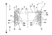
図2(a)、(b)は各々、本発明を適用したレンズ駆動装置1において、ヨーク18の内側に移動体3を挿入した状態を斜め下方(撮像素子側)からみたときの斜視図、およびその分解斜視図である。図3(a)は、本発明を適用したレンズ駆動装置1において、磁気駆動回路5を構成する永久磁石17とコイル30x、30yをレンズ光軸方向Xからみたときの位置関係等を模式的に示す説明図である。なお、図2(a)、(b)には、移動体3のうち、コイルホルダ13のみを図示してある。
(Detailed configuration of magnetic drive circuit)
2 (a) and 2 (b) are perspective views of the lens driving device 1 to which the present invention is applied, as seen from the obliquely lower side (imaging device side) in a state in which the moving
図1、図2(a)、(b)および図3(a)に示すように、本形態のレンズ駆動装置1において、レンズ光軸方向Xからみたとき、レンズ121は円形であるが、支持体2に用いたヨーク18は矩形箱状である。従って、ヨーク18は、角筒状胴部184を備えており、角筒状胴部184の上面側には、入射窓120が形成された上板部185を備えている。本形態において、角筒状胴部184は四角筒状であり、レンズ光軸方向Xからみたときに四角形の辺に相当する各位置に4つの側板部181を備えている。
As shown in FIGS. 1, 2A, 2B, and 3A, in the lens driving device 1 of the present embodiment, the
本形態において、4つの側板部181の各々の内面には永久磁石17が固着されており、かかる永久磁石17は各々、矩形の平板状永久磁石からなる。4つの永久磁石17はいずれもレンズ光軸方向Xにおいて2分割されており、いずれにおいても内面と外面とが異なる極に着磁されている。例えば、4つの永久磁石17では、例えば、上半分では内面がN極に着磁され、外面がS極に着磁され、下半分では、内面がS極に着磁され、外面がN極に着磁されている。このため、4つの永久磁石17では、隣接する永久磁石同士において、磁極の配置が同一であり、コイルに対する鎖交磁束線を効率よく発生させることができる。
In this embodiment,
移動体3は、レンズ121等を保持する円筒状のレンズホルダ12と、コイル(コイル30x、30y)が外周側面に巻回されたコイルホルダ13とを備えており、レンズホルダ12およびコイルホルダ13によって移動体3の側壁部分が構成されている。レンズホルダ12は、上半部が大径の大径円筒部12bになっており、下半部が大径円筒部12bより小径の小径円筒部12aになっている。コイルホルダ13は、レンズホルダ12を内側に保持するための円形のレンズホルダ収納穴130を備えている。
The moving
本形態では、コイルホルダ13をレンズ光軸方向Xからみたとき、内周形状は円形であるが、コイルホルダ13の外周形状を規定する外周側面131は四角形であり、四角形の4つの辺に相当する各位置に4つの面132を備えている。かかるコイルホルダ13の外周側面131において、レンズ光軸方向Xにおける両端部および中央位置には、その全周にわたってリブ状突起131a、131b、131cが形成されており、撮像素子側端部に形成されたリブ状突起131aと中央位置に形成されたリブ状突起131bとに挟まれた凹部は第1コイル巻回部132aになっており、被写体側端部に形成されたリブ状突起131cと中央位置に形成されたリブ状突起131bとに挟まれた凹部は第2コイル巻回部132bになっている。
In this embodiment, when the
また、コイルホルダ13において、4つの面132の各々には、第1コイル巻回部132a、および第2コイル巻回部132bの各々に対して、四角形の角部分を避けるように除去してなる矩形の貫通穴(貫通穴133a、133b)が形成されており、かかる貫通穴133a、133bは、コイルホルダ13の側面壁を内外方向で貫通している。このようにして、本形態では、コイルホルダ13の貫通穴133a、133bによって、移動体3の外周側面131で内側に凹む肉抜き部が構成されている。
Further, in the
貫通穴133a、133bは、周方向においては、コイルホルダ13の外周側面131において隣接する角部分で挟まれた中央部分に、各面132の周方向の長さ寸法(四角形の辺の寸法)の約1/3の寸法で形成されている。このため、コイルホルダ13の角部分には、レンズ光軸方向Xに向けて延びる肉厚の支柱部分134が同等の太さで形成されている。
In the circumferential direction, the through
また、貫通穴133a、133bは、第1コイル巻回部132a、および第2コイル巻回部132bの幅方向(レンズ光軸方向X)の全体にわたって形成されているが、リブ状突起131a、131b、131cにかかるようには形成されていない。このため、貫通穴133a、133b(肉抜き部)は、コイルホルダ13(移動体3)のレンズ光軸方向Xにおける途中部分のみに形成され、両端部を避けた位置に形成されている。
The through
このように構成したコイルホルダ13において、第1コイル巻回部132aにはコイル30xが巻回されており、第2コイル巻回部132bにはコイル30yが巻回されている。ここで、第1コイル巻回部132aおよび第2コイル巻回部132bは、レンズ光軸方向Xからみたとき四角形であるため、コイル30x、30yはいずれも四角筒状に巻回されている。なお、4つの永久磁石17はいずれも光軸方向において2分割されており、いずれにおいても内面と外面とが異なる極に着磁されているため、2つのコイル30x、30yにおける巻回方向は反対である。
In the
また、貫通穴133a、133bは、レンズ光軸方向Xにおける長さ寸法は、第1コイル巻回部132a、および第2コイル巻回部132bのレンズ光軸方向Xにおける長さ寸法と等しく、レンズ光軸方向Xにおいて、第1コイル巻回部132aおよび第2コイル巻回部132bの全体にわたって形成されているが、コイル30x、30yは、第1コイル巻回部132aおよび第2コイル巻回部132bの全体にわたって巻回され、貫通穴133a、133bの形成領域の全体を通っている。このため、貫通穴133a、133bは、外側で開口する開口部がコイル30x、30yで塞がれている。また、コイルホルダ13のレンズホルダ収納穴130にはレンズホルダ12が装着されているため、貫通穴133a、133bのうち、レンズ光軸方向Xの被写体側に位置する貫通穴133bは、内側で開口する開口部がレンズホルダ12の上半部に形成された大径円筒部12bで塞がれている一方、光軸方向の撮像素子側に位置する貫通穴133aは、レンズホルダ12の下半部に形成された小径円筒部12aが対向している。
The through
このように構成したコイルホルダ13は、図2(a)、(b)に示すように、ヨーク18の内側に配置される。その結果、図3(a)に示すように、コイル30x、30yの4つの辺部は各々、ヨーク18の角筒状胴部184の内面に固着された永久磁石17に対向することになる。
The
(基本的な動作)
図4は、図1に示すレンズ駆動装置1の動作を模式的に示す説明図である。なお、図4の左半分は、移動体3が無限遠の位置(通常撮影位置)にあるときの図を示しており、図4の右半分は、移動体3がマクロ位置(接写撮影位置)にあるときの図を示している。
(Basic operation)
FIG. 4 is an explanatory diagram schematically showing the operation of the lens driving device 1 shown in FIG. The left half of FIG. 4 shows a view when the moving
本形態のレンズ駆動装置1において、移動体3は、通常は撮像素子側(撮像素子側)に位置しており、このような状態において、コイル30x、30yに所定方向の電流を流すと、コイル30x、30yは、それぞれ上向き(前側)の電磁力を受けることになる。これにより、コイル30x、30yが固着された移動体3は、被写体側(前側)に移動し始めることになる。このとき、バネ部材14yと移動体3の前端との間、およびバネ部材14xと移動体3の後端との間には、移動体3の移動を規制する弾性力が発生する。このため、移動体3を前側に移動させようとする電磁力と、移動体3の移動を規制する弾性力とが釣り合ったとき、移動体3は停止する。その際、バネ部材14x、14yによって移動体3に働く弾性力に応じて、コイル30x、30yに流す電流量を調整することで、移動体3(移動体3)を所望の位置に停止させることができる。
In the lens driving device 1 of the present embodiment, the moving
本形態では、弾性力(応力)と変位量(歪み量)との間に線形関係が成立するバネ部材14x、14yを用いていることから、移動体3の移動量とコイル30x、30yに流す電流との間のリニアリティを向上させることができる。また、2つのバネ部材14x、14yを用いていることから、移動体3が停止したときに光軸Xの方向に大きな釣り合いの力が加わることになり、光軸Xの方向に遠心力や衝撃力等の他の力が働いたとしても、より安定に移動体3を停止させることができる。さらに、レンズ駆動装置1では、移動体3を停止させるのに、衝突材(緩衝材)等に衝突させて停止させるのではなく、電磁力と弾性力との釣り合いを利用して停止させることとしているので、衝突音の発生を防ぐことも可能である。
In this embodiment, since the
(本形態の主な効果)
以上説明したように、本形態のレンズ駆動装置1において、レンズ121は円形であるが、かかるレンズ形状に関係なく、コイル30x、30yは四角形であり、永久磁石17は、支持体3において内周面が四角形に形成されたヨーク18の角筒状胴部184の辺に相当する複数の内面の各々に固着された平板状永久磁石である。このため、移動体3と支持体2との間において、移動体3の外周側に十分なスペースがない場合でも、コイル30x、30yと永久磁石17との対向面積が広いので、十分な推力を発揮することができる。
(Main effects of this form)
As described above, in the lens driving device 1 of the present embodiment, the
例えば、図3(a)に示す本発明に係る構成と、図5に示す比較例に係る構成とにおいて、ヨーク18のサイズを一定とし、永久磁石17からヨーク18までのクリアランスを一定にし、さらにアンペアターンを一定とするなど、サイズや駆動条件などを同一として、0μmで示す基準位置(移動体の移動範囲のうち最も撮像素子側の位置)と、150μmで示す移動位置(最も撮像素子側の位置から移動体が150μmだけ被写体側に移動した位置)とにおいて、コイルに対する無励磁状態における吸着力Fi(g)と、吸着状態からの脱着力Fo(g)とを比較すると、以下の比較結果
本発明に係る構成 比較例に係る構成
Fi Fo Fi Fo
0μm 1.02 −2.12 0.76 −2.03
150μm 0.60 −2.71 0.59 −2.40
が得られた。
For example, in the configuration according to the present invention shown in FIG. 3A and the configuration according to the comparative example shown in FIG. 5, the size of the
Configuration according to the present invention Configuration according to a comparative example
Fi Fo Fi Fo
0 μm 1.02 -2.12 0.76 -2.03
150 μm 0.60 -2.71 0.59 -2.40
was gotten.
また、推力(吸着力Fi−脱着力Fo)を比較すると、以下の比較結果
本発明に係る構成 比較例に係る構成
0μm −3.14 −2.79
150μm −3.31 −2.99
が得られた。このように、本発明を適用すると、大きな推力を得ることができることがわかる。また、上記の効果のうち、無励磁状態における吸着力Fiが向上した理由は、リング状の磁性片61を用いた場合において、永久磁石17として、平板状永久磁石を用いたことによる効果であり、かかる効果によれば、磁性片61と永久磁石17との間に作用する磁気的な吸引力を利用して移動体3の位置や姿勢を確実に制御することができるという利点がある。
Further, when the thrust (adsorption force Fi−desorption force Fo) is compared, the following comparison results
Configuration according to the present invention Configuration according to a comparative example 0 μm −3.14 −2.79
150 μm −3.31 −2.99
was gotten. Thus, it can be seen that a large thrust can be obtained by applying the present invention. Further, among the above effects, the reason why the attractive force Fi in the non-excited state is improved is an effect obtained by using a plate-like permanent magnet as the
また、移動体3をレンズ光軸方向Xからみたときに、移動体3の外周側面(コイルホルダ13の外周側面131)は、コイル30x、30yと同じ四角形であるため、移動体3の外周面(コイルホルダ13の外周側面131)にコイル30x、30yを巻回するだけで、コイル30x、30yを四角形に巻回することができる。
When the moving
また、移動体3の外周側面には、コイルホルダ13に形成された貫通穴133a、133bによって、内側に向けて凹む肉抜き部が形成されているため、移動体3の軽量化を図ることができるので、十分な推力を得ることができる。
In addition, since the outer side surface of the moving
また、貫通穴133a、133b(肉抜き部)は、コイルホルダ13の外周側面131の角部を避けた面132に形成されているため、コイルホルダ13の角部分には、レンズ光軸方向Xに延びた肉厚部分が支柱部分134として形成される。このため、貫通穴133a、133bの形成によって、移動体3の軽量化を図った場合でも、移動体3は十分な強度を有することになる。また、コイルホルダ13の角部に貫通穴133a、133bに形成すると、コイル30x、30yを巻回した際、角部分でコイル30x、30yの形状が崩れ、コイル30x、30yを四角形に巻回できないが、本形態では、角部を避けた面132に貫通穴133a、133bが形成されているため、貫通穴133a、133bを通るようにコイル30x、30yを巻回した場合でも、コイル30x、30yを四角形に巻回することができる。
Further, since the through
また、貫通穴133a、133bは、多角形の辺の中央部分に形成されているため、多角形の複数の角部分の各々に、レンズ光軸方向Xに延びた肉厚の支柱部分134を同等の太さで形成できるので、移動体の周方向における重量バランスや強度バランスを好適に確保することができる。しかも、貫通穴133a、133bは、コイルホルダ13のレンズ光軸方向Xにおける両端部を避けた途中部分に形成されているため、コイルホルダ13の両端が強度低下することを防止することができる。それ故、コイルホルダ13の周りにコイル30x、30yを巻回する際、線材に十分な荷重をかけることができるので、コイル30x、30yを密に整列した状態に巻回できる分、十分な推力を得ることができる。
Further, since the through
また、本形態では、移動体3をレンズホルダ12とコイルホルダ13とに分割したので、コイルホルダ13にコイル30x、30yを巻回した後、レンズホルダ12をレンズホルダ収納穴130に収納、装着した構成を採用することができ、コイル30x、30yを巻回する際、レンズ121を損傷する等の事態を回避することができる。
In this embodiment, since the moving
また、ヨーク18は、角筒状胴部184の上面に上板部185を備えた箱形状を有しているため、永久磁石17とコイル30x、30yとの間に構成される磁路からの漏れ磁束を少なくすることができる。従って、コイルホルダ13の移動量と、コイル30x、30yに流す電流との間の推力を向上させることができる。また、レンズ駆動装置1を携帯電話に組み付けた場合、周囲の電子部品への漏れ磁束を低減できる。
Further, since the
(他の実施の形態)
上記形態において、レンズ光軸方向Xからみたとき、角筒状胴部184およびコイル30x、30yが四角形であったが、略四角形であってもよい。すなわち、角筒状胴部184およびコイル30x、30yについては、四角形の角が丸まっている形状であってもよく、さらには、図3(b)に示すように、四角形の角が直線的に削られて例えば八角形になっているが、角部分で削れた部分が短くて四角形と同様な形状になっている構成でもよい。
(Other embodiments)
In the above embodiment, when viewed from the lens optical axis direction X, the rectangular
また、上記形態では、角筒状胴部184およびコイル30x、30yが四角形であったが、角筒状胴部およびコイルの形状については、多角形であれば、四角形に限らず、六角形や八角形等であってもよく、また、永久磁石17については、ヨークの角筒状胴部の全ての面に固定されている構成の他、周方向において1つおきに位置する面に固定されている構成を採用してもよい。
Further, in the above embodiment, the rectangular
上記形態では、コイルホルダ13の外周形状も多角形であったが、コイルホルダ13が円筒形であって、その外周側面に形成した突起等を利用して、多角形に巻回したコイル30x、30yをコイルホルダ13の外周側面に固定した構造を採用してもよい。
In the above embodiment, the outer shape of the
上記形態では、移動体3をレンズホルダ12とコイルホルダ13とに分割し、レンズホルダ12の胴部に対して、移動体3の側壁部分の一部を除去してなる凹部あるいは穴からなる肉抜き部を構成する貫通穴133a、133bを形成したが、レンズホルダ12の胴部に対して、その一部を除去してなる凹部あるいは穴を形成し、かかる凹部あるいは穴を肉抜き部として利用してもよい。
In the above embodiment, the moving
上記形態では、移動体3をレンズホルダ12とコイルホルダ13とに分割したが、一部品として移動体を構成してもよく、この場合でも、移動体3の外周側面あるいは内周側面に対して、その一部を除去してなる凹部あるいは穴を肉抜き部として形成すれば、移動体3の軽量化を図ることができる。この場合の肉抜き部の形成位置等についても、上記形態において、レンズホルダ12に貫通穴133a、133bを形成した際に角部を避ける等の構成を採用することが好ましい。
In the above embodiment, the moving
1 レンズ駆動装置
2 支持体
3 移動体
11 スペーサ
12 レンズホルダ
13 コイルホルダ
14x、14y バネ部材
17 永久磁石
18 ヨーク
19 撮像素子ホルダ
30x、30y コイル
61 磁性片
133a、133b 貫通穴(肉抜き部)
DESCRIPTION OF SYMBOLS 1 Lens drive
Claims (6)
前記永久磁石は、多角形の辺に相当する位置に配置された複数の平板状永久磁石からなり、
前記移動体には、前記平板状永久磁石との間に磁気吸引力を発生させる磁性片が搭載されていることを特徴とするレンズ駆動装置。 A support body, a moving body that holds the lens, a coil that is held on the outer peripheral side surface of the moving body, and a permanent magnet that is held by the support body so as to face the coil. A lens driving device having a magnetic driving circuit for driving along an axis,
The permanent magnet is composed of a plurality of plate-like permanent magnets arranged at positions corresponding to polygon sides,
2. A lens driving device according to claim 1, wherein a magnetic piece for generating a magnetic attractive force is mounted between the movable body and the flat permanent magnet.
前記複数の平板状永久磁石は各々、前記角筒状胴部において前記多角形の辺に相当する複数の内面に固着されていることを特徴とする請求項1乃至3の何れか一項に記載のレンズ駆動装置。 The support body includes a rectangular tube-shaped body portion whose inner peripheral shape surrounding the moving body is a polygon,
4. The plurality of flat permanent magnets are respectively fixed to a plurality of inner surfaces corresponding to the sides of the polygon in the rectangular tube-shaped body portion. 5. Lens drive device.
前記複数の平板状永久磁石は、前記角筒状胴部において四角形の辺に相当する4つの内面の各々に固着され、
前記コイルは、前記4つの内面に固着された前記平板状永久磁石の各々に対向する4つの辺部を備えた四角形あるいは略四角形に巻回されていることを特徴とする請求項4に記載のレンズ駆動装置。 The rectangular tube body is formed in a rectangular or substantially quadrangular rectangular tube shape when viewed from the lens optical axis direction,
The plurality of plate-like permanent magnets are fixed to each of four inner surfaces corresponding to the sides of a quadrangle in the rectangular tube body,
5. The coil according to claim 4, wherein the coil is wound in a quadrangular shape or a substantially quadrangular shape having four sides facing each of the plate-like permanent magnets fixed to the four inner surfaces. Lens drive device.
Priority Applications (1)
| Application Number | Priority Date | Filing Date | Title |
|---|---|---|---|
| JP2008082314A JP2009237192A (en) | 2008-03-27 | 2008-03-27 | Lens driving device |
Applications Claiming Priority (1)
| Application Number | Priority Date | Filing Date | Title |
|---|---|---|---|
| JP2008082314A JP2009237192A (en) | 2008-03-27 | 2008-03-27 | Lens driving device |
Publications (1)
| Publication Number | Publication Date |
|---|---|
| JP2009237192A true JP2009237192A (en) | 2009-10-15 |
Family
ID=41251215
Family Applications (1)
| Application Number | Title | Priority Date | Filing Date |
|---|---|---|---|
| JP2008082314A Pending JP2009237192A (en) | 2008-03-27 | 2008-03-27 | Lens driving device |
Country Status (1)
| Country | Link |
|---|---|
| JP (1) | JP2009237192A (en) |
Cited By (7)
| Publication number | Priority date | Publication date | Assignee | Title |
|---|---|---|---|---|
| CN102298189A (en) * | 2010-06-25 | 2011-12-28 | 思考电机(上海)有限公司 | Lens driving device, automatic focusing camera and mobile terminal device |
| CN102313964A (en) * | 2010-07-02 | 2012-01-11 | 思考电机(上海)有限公司 | Lens driving device, automatic focusing camera and mobile terminal device |
| CN102457153A (en) * | 2010-10-20 | 2012-05-16 | 鸿富锦精密工业(深圳)有限公司 | Voice coil motor |
| US20130154396A1 (en) * | 2011-12-19 | 2013-06-20 | Hon Hai Precision Industry Co., Ltd. | Voice coil motor |
| CN103178682A (en) * | 2011-12-21 | 2013-06-26 | 鸿富锦精密工业(深圳)有限公司 | Voice coil motor |
| CN103201934A (en) * | 2010-11-02 | 2013-07-10 | Lg伊诺特有限公司 | Voice coil motor and driving method thereof |
| CN105511046A (en) * | 2015-12-29 | 2016-04-20 | 上海比路电子有限公司 | Mid-mounted motor |
Citations (5)
| Publication number | Priority date | Publication date | Assignee | Title |
|---|---|---|---|---|
| WO2006126545A1 (en) * | 2005-05-24 | 2006-11-30 | Matsushita Electric Industrial Co., Ltd. | Camera module |
| JP2007148354A (en) * | 2005-10-28 | 2007-06-14 | Nidec Sankyo Corp | Lens drive unit |
| JP2007226011A (en) * | 2006-02-24 | 2007-09-06 | Nidec Sankyo Corp | Lens drive unit |
| JP2007248844A (en) * | 2006-03-16 | 2007-09-27 | Mitsumi Electric Co Ltd | Camera module |
| JP2008058946A (en) * | 2007-06-13 | 2008-03-13 | Tricore Corp | VOICE COIL MOTOR TYPE mp FOCUSING ACTUATOR |
-
2008
- 2008-03-27 JP JP2008082314A patent/JP2009237192A/en active Pending
Patent Citations (5)
| Publication number | Priority date | Publication date | Assignee | Title |
|---|---|---|---|---|
| WO2006126545A1 (en) * | 2005-05-24 | 2006-11-30 | Matsushita Electric Industrial Co., Ltd. | Camera module |
| JP2007148354A (en) * | 2005-10-28 | 2007-06-14 | Nidec Sankyo Corp | Lens drive unit |
| JP2007226011A (en) * | 2006-02-24 | 2007-09-06 | Nidec Sankyo Corp | Lens drive unit |
| JP2007248844A (en) * | 2006-03-16 | 2007-09-27 | Mitsumi Electric Co Ltd | Camera module |
| JP2008058946A (en) * | 2007-06-13 | 2008-03-13 | Tricore Corp | VOICE COIL MOTOR TYPE mp FOCUSING ACTUATOR |
Cited By (17)
| Publication number | Priority date | Publication date | Assignee | Title |
|---|---|---|---|---|
| CN102298189B (en) * | 2010-06-25 | 2013-08-21 | 思考电机(上海)有限公司 | Lens driving device, automatic focusing camera and mobile terminal device |
| CN102298189A (en) * | 2010-06-25 | 2011-12-28 | 思考电机(上海)有限公司 | Lens driving device, automatic focusing camera and mobile terminal device |
| CN102313964A (en) * | 2010-07-02 | 2012-01-11 | 思考电机(上海)有限公司 | Lens driving device, automatic focusing camera and mobile terminal device |
| CN102313964B (en) * | 2010-07-02 | 2013-06-19 | 思考电机(上海)有限公司 | Lens driving device, automatic focusing camera and mobile terminal device |
| CN102457153A (en) * | 2010-10-20 | 2012-05-16 | 鸿富锦精密工业(深圳)有限公司 | Voice coil motor |
| CN105763016A (en) * | 2010-11-02 | 2016-07-13 | Lg伊诺特有限公司 | Voice coil motor and driving method thereof |
| CN103201934A (en) * | 2010-11-02 | 2013-07-10 | Lg伊诺特有限公司 | Voice coil motor and driving method thereof |
| JP2013541319A (en) * | 2010-11-02 | 2013-11-07 | エルジー イノテック カンパニー リミテッド | Voice coil motor and driving method thereof |
| JP2015180189A (en) * | 2010-11-02 | 2015-10-08 | エルジー イノテック カンパニー リミテッド | Voice coil motor and driving method thereof |
| CN105720783A (en) * | 2010-11-02 | 2016-06-29 | Lg伊诺特有限公司 | Voice coil motor and driving method thereof |
| US9429734B2 (en) | 2010-11-02 | 2016-08-30 | Lg Innotek Co., Ltd. | Voice coil motor and driving method thereof |
| US9448383B2 (en) | 2010-11-02 | 2016-09-20 | Lg Innotek Co., Ltd. | Voice coil motor and driving method thereof |
| US10254504B2 (en) | 2010-11-02 | 2019-04-09 | Lg Innotek Co., Ltd. | Voice coil motor and driving method thereof |
| US20130154396A1 (en) * | 2011-12-19 | 2013-06-20 | Hon Hai Precision Industry Co., Ltd. | Voice coil motor |
| CN103178682A (en) * | 2011-12-21 | 2013-06-26 | 鸿富锦精密工业(深圳)有限公司 | Voice coil motor |
| CN105511046A (en) * | 2015-12-29 | 2016-04-20 | 上海比路电子有限公司 | Mid-mounted motor |
| WO2017113547A1 (en) * | 2015-12-29 | 2017-07-06 | 上海比路电子有限公司 | Mid-motor |
Similar Documents
| Publication | Publication Date | Title |
|---|---|---|
| JP5140572B2 (en) | Optical unit with shake correction function | |
| US8379337B2 (en) | Lens drive device | |
| JP2009237193A (en) | Lens driving device | |
| JP4250409B2 (en) | Lens drive device | |
| US9638929B2 (en) | Electromagnetic driving device | |
| JP5140573B2 (en) | Optical unit with shake correction function | |
| JP4838744B2 (en) | Lens drive device | |
| JP2009237192A (en) | Lens driving device | |
| WO2007026830A1 (en) | Lens drive device | |
| US20080117536A1 (en) | Lens driving apparatus and its manufacturing method | |
| JP4932591B2 (en) | Lens drive device | |
| JP5430107B2 (en) | Lens drive device | |
| JP5591571B2 (en) | Lens drive device | |
| JPWO2008129827A1 (en) | Lens drive device | |
| JP2008116901A (en) | Lens drive unit | |
| JP2006259032A (en) | Lens driving device | |
| JP2018180353A (en) | Lens drive device | |
| JP2010014920A (en) | Lens drive device | |
| JP2009251474A (en) | Lens unit and imaging apparatus | |
| JP2010211180A (en) | Lens drive device | |
| JP2007121547A (en) | Lens drive device | |
| JP2010008946A (en) | Lens drive device | |
| JP5359443B2 (en) | Lens actuator | |
| JP6793350B2 (en) | Linear actuator, lens barrel and camera | |
| TWI437795B (en) | Voice coil motor |
Legal Events
| Date | Code | Title | Description |
|---|---|---|---|
| A621 | Written request for application examination |
Free format text: JAPANESE INTERMEDIATE CODE: A621 Effective date: 20110113 |
|
| A521 | Written amendment |
Free format text: JAPANESE INTERMEDIATE CODE: A523 Effective date: 20111202 |
|
| A977 | Report on retrieval |
Free format text: JAPANESE INTERMEDIATE CODE: A971007 Effective date: 20120719 |
|
| A131 | Notification of reasons for refusal |
Free format text: JAPANESE INTERMEDIATE CODE: A131 Effective date: 20120724 |
|
| A521 | Written amendment |
Free format text: JAPANESE INTERMEDIATE CODE: A523 Effective date: 20120903 |
|
| A131 | Notification of reasons for refusal |
Free format text: JAPANESE INTERMEDIATE CODE: A131 Effective date: 20130312 |
|
| A02 | Decision of refusal |
Free format text: JAPANESE INTERMEDIATE CODE: A02 Effective date: 20130806 |