JP2009236176A - Drive force transmitting device - Google Patents

Drive force transmitting device Download PDF

Info

Publication number
JP2009236176A
JP2009236176A JP2008081150A JP2008081150A JP2009236176A JP 2009236176 A JP2009236176 A JP 2009236176A JP 2008081150 A JP2008081150 A JP 2008081150A JP 2008081150 A JP2008081150 A JP 2008081150A JP 2009236176 A JP2009236176 A JP 2009236176A
Authority
JP
Japan
Prior art keywords
clutch
pressing
cam
main
transmission device
Prior art date
Legal status (The legal status is an assumption and is not a legal conclusion. Google has not performed a legal analysis and makes no representation as to the accuracy of the status listed.)
Pending
Application number
JP2008081150A
Other languages
Japanese (ja)
Inventor
Naoyuki Kokubo
直之 小久保
Current Assignee (The listed assignees may be inaccurate. Google has not performed a legal analysis and makes no representation or warranty as to the accuracy of the list.)
JTEKT Corp
Original Assignee
JTEKT Corp
Priority date (The priority date is an assumption and is not a legal conclusion. Google has not performed a legal analysis and makes no representation as to the accuracy of the date listed.)
Filing date
Publication date
Application filed by JTEKT Corp filed Critical JTEKT Corp
Priority to JP2008081150A priority Critical patent/JP2009236176A/en
Publication of JP2009236176A publication Critical patent/JP2009236176A/en
Pending legal-status Critical Current

Links

Images

Landscapes

  • Arrangement And Driving Of Transmission Devices (AREA)
  • Mechanical Operated Clutches (AREA)

Abstract

<P>PROBLEM TO BE SOLVED: To provide a drive force transmitting device capable of enhancing traction performance in an initial period of a wheel speed difference generation and capable of enhancing traveling stability of a vehicle. <P>SOLUTION: The drive force transmitting device 6 is provided with a piston 62 for axially pressing a main clutch 34 from an opposite side in an axial direction of a main cam 39 and an interlocking member 64 for reducing a pressing force which the piston 62 applies to the main clutch 34 based on increase of a pressing force generated by a cam mechanism 36. <P>COPYRIGHT: (C)2010,JPO&INPIT

Description

本発明は、駆動力伝達装置に関するものである。   The present invention relates to a driving force transmission device.

従来、円筒状の第1回転部材と、該第1回転部材内に回転自在に同軸配置された軸状の第2回転部材とを備え、これら第1回転部材と第2回転部材との間に設けられたクラッチ機構により第1回転部材及び第2回転部材をトルク伝達可能に連結可能とした駆動力伝達装置がある。このような駆動力伝達装置は、4輪駆動車における駆動伝達系の途中に設けられ、主駆動輪(主に前輪)と補助駆動輪(主に後輪)との間の駆動力配分特性を変更するようになっている。   2. Description of the Related Art Conventionally, a cylindrical first rotating member and a shaft-shaped second rotating member that is coaxially arranged rotatably in the first rotating member are provided, and between the first rotating member and the second rotating member. There is a driving force transmission device in which a first rotating member and a second rotating member can be connected so as to transmit torque by a clutch mechanism provided. Such a driving force transmission device is provided in the middle of a drive transmission system in a four-wheel drive vehicle, and has a driving force distribution characteristic between main driving wheels (mainly front wheels) and auxiliary driving wheels (mainly rear wheels). It is supposed to change.

例えば特許文献1には、クラッチ機構(メインクラッチ)の軸方向に並置されるパイロットクラッチと、メインクラッチとパイロットクラッチの間に設けられ該パイロットクラッチの作動によりメインクラッチを軸方向に押圧するカム機構とから構成された押圧力発生手段を備えた駆動力伝達装置が開示されている。カム機構は、同一回転軸上で互いに相対回転可能な第1カム部材及び第2カム部材と、これらの各対向面にそれぞれ形成されたカム溝に挟持されるカムフォロアとを備えている。そして、カム機構は、パイロットクラッチを介して伝達される第1回転部材と第2回転部材との回転差に基づくトルクによって第1カム部材と第2カム部材とが相対回転することでカムフォロアがカム溝を転動し、第1カム部材と第2カム部材とが離間して第1カム部材がメインクラッチを押圧するように構成されている。
特開2002−61677号公報
For example, Patent Document 1 discloses a pilot clutch that is juxtaposed in the axial direction of a clutch mechanism (main clutch), and a cam mechanism that is provided between the main clutch and the pilot clutch and presses the main clutch in the axial direction by the operation of the pilot clutch. A driving force transmission device having a pressing force generating means constituted by the following is disclosed. The cam mechanism includes a first cam member and a second cam member that can rotate relative to each other on the same rotation shaft, and a cam follower that is sandwiched between cam grooves formed on the respective opposing surfaces. The cam mechanism causes the cam follower to cam as a result of the first cam member and the second cam member rotating relative to each other by torque based on the rotational difference between the first rotating member and the second rotating member transmitted via the pilot clutch. The groove is rolled so that the first cam member and the second cam member are separated and the first cam member presses the main clutch.
JP 2002-61677 A

ところで、上記特許文献1では、第1回転部材と第2回転部材との間に相対回転が生じないと、即ち前輪と後輪との間に車輪速差が生じないとクラッチ機構が摩擦係合せずトルクが伝達されない。そのため、例えば車両の発進時にスリップが発生する場合等のように車輪速差の発生初期では、補助駆動輪に十分なトルクが配分されず、スリップが大きくなってトラクション性能が低下する虞があった。なお、このような問題は、カム機構によってメインクラッチを押圧する場合に限らず、第1回転部材と第2回転部材との回転差に基づいて発生する軸方向の押圧力によってクラッチ機構を押圧する構成を備えた駆動力伝達装置において同様に発生する。   By the way, in Patent Document 1, the clutch mechanism is frictionally engaged unless a relative rotation occurs between the first rotating member and the second rotating member, that is, if there is no wheel speed difference between the front wheel and the rear wheel. Torque is not transmitted. For this reason, for example, when a slip occurs at the start of the vehicle, there is a possibility that sufficient torque is not distributed to the auxiliary drive wheels at the initial stage of the difference in wheel speed, resulting in a large slip and a decrease in traction performance. . Such a problem is not limited to the case where the main clutch is pressed by the cam mechanism, but the clutch mechanism is pressed by the axial pressing force generated based on the rotation difference between the first rotating member and the second rotating member. The same occurs in the driving force transmission device having the configuration.

そこで、第1回転部材と第2回転部材との回転差に基づいて発生する軸方向の押圧力が作用しないときにおいてもクラッチ機構を押圧する、即ちプレトルクをクラッチ機構に付与することで、補助駆動輪にトルクを常時伝達し、発進時のような車輪速差の発生初期などにおけるトラクション性能を向上させることが考えられる。しかしながら、補助駆動輪にトルクを常時伝達するようにすると、例えば車両の旋回半径が小さい場合に前後輪間の回転差を吸収できず、前後輪にブレーキがかかったような所謂タイトコーナブレーキング現象が発生する等、車両の走行安定性が低下してしまう虞がある。   Therefore, even when the axial pressing force generated based on the rotation difference between the first rotating member and the second rotating member does not act, the clutch mechanism is pressed, that is, the pre-torque is applied to the clutch mechanism, thereby assisting driving. It is conceivable to constantly transmit torque to the wheels to improve the traction performance in the initial stage of occurrence of a wheel speed difference such as when starting. However, when torque is always transmitted to the auxiliary drive wheels, for example, when the turning radius of the vehicle is small, the so-called tight corner braking phenomenon in which the difference in rotation between the front and rear wheels cannot be absorbed and the front and rear wheels are braked. There is a possibility that the running stability of the vehicle may be reduced.

本発明は上記問題点を解決するためになされたものであって、その目的は、車輪速差の発生初期におけるトラクション性能の向上を図るとともに車両の走行安定性の向上を図ることができる駆動力伝達装置を提供することにある。   The present invention has been made to solve the above-described problems, and its object is to improve the traction performance at the initial stage of occurrence of the wheel speed difference and the driving force capable of improving the running stability of the vehicle. It is to provide a transmission device.

上記目的を達成するため、請求項1に記載の発明は、円筒状の第1回転部材と、前記第1回転部材内に回転自在に同軸配置された軸状の第2回転部材と、前記第1回転部材と一体回転するアウタクラッチプレート及び前記第2回転部材と一体回転するインナクラッチプレートが交互に配置されたクラッチ機構と、軸方向の押圧力を発生させる押圧力発生手段と、前記押圧力発生手段によって発生された押圧力に応じて軸方向移動し前記クラッチ機構を押圧する第1の押圧部材とを備え、前記第1回転部材と前記第2回転部材との間のトルク伝達容量を変更可能に構成された駆動力伝達装置において、前記第1の押圧部材の軸方向反対側から前記クラッチ機構を軸方向に押圧する第2の押圧部材と、前記押圧力発生手段にて発生する押圧力の増加に基づいて前記第2の押圧部材が前記クラッチ機構へ付与する押圧力を減少させる減少手段とを備えたことを要旨とする。   In order to achieve the above object, the invention according to claim 1 includes a cylindrical first rotating member, a shaft-shaped second rotating member that is coaxially disposed in the first rotating member, and the first rotating member. A clutch mechanism in which an outer clutch plate that rotates integrally with one rotating member and an inner clutch plate that rotates integrally with the second rotating member are alternately arranged; a pressing force generating means for generating an axial pressing force; and the pressing force A first pressing member that moves in the axial direction according to the pressing force generated by the generating means and presses the clutch mechanism, and changes a torque transmission capacity between the first rotating member and the second rotating member. In the driving force transmission device configured to be possible, a second pressing member that presses the clutch mechanism in the axial direction from an axially opposite side of the first pressing member, and a pressing force generated by the pressing force generating means Increase Said second pressing member is summarized in that with a reduction means for reducing the pressing force applied to the clutch mechanism based on.

上記構成によれば、押圧力発生手段の非作動時においても、クラッチ機構は第2の押圧部材によって押圧されることで摩擦係合し、所定のトルクを補助駆動輪に伝達可能になるため、例えば車両の発進時にスリップが発生する場合等のように車輪速差の発生初期においても、補助駆動輪に所定のトルクが配分され、スリップが大きくなることを防止してトラクション性能の向上を図ることができる。また、減少手段により、押圧力発生手段にて発生する押圧力の増加に基づいて第2の押圧部材がクラッチ機構へ付与する押圧力を減少させることでクラッチ機構の摩擦係合力を減少させて、例えば車両の旋回半径が小さい場合にタイトコーナブレーキング現象の発生を防止し、車両の走行安定性の向上を図ることができる。   According to the above configuration, even when the pressing force generating means is not in operation, the clutch mechanism is frictionally engaged by being pressed by the second pressing member, so that a predetermined torque can be transmitted to the auxiliary driving wheel. For example, even when slip occurs at the start of the vehicle, a predetermined torque is distributed to the auxiliary drive wheels even in the early stage of occurrence of the wheel speed difference to prevent the slip from increasing and improve the traction performance. Can do. Further, the reducing means reduces the frictional engagement force of the clutch mechanism by reducing the pressing force applied to the clutch mechanism by the second pressing member based on the increase of the pressing force generated by the pressing force generating means, For example, when the turning radius of the vehicle is small, the occurrence of a tight corner braking phenomenon can be prevented, and the running stability of the vehicle can be improved.

請求項2に記載の発明は、請求項1に記載の駆動力伝達装置において、前記インナクラッチプレートには、該インナクラッチプレートにおける前記アウタクラッチプレートと摺動する摺動部の内周側に貫通孔が形成され、前記減少手段は、前記貫通孔に挿通され、前記第1の押圧部材及び前記第2の押圧部材の何れか一方の軸方向移動により、前記第1の押圧部材及び前記第2の押圧部材の何れか他方を連動して移動させる連動部材であることを要旨とする。上記構成によれば、連動部材により第1の押圧部材と第2の押圧部材とが連動して移動するため、第1の押圧部材がクラッチ機構側に軸方向移動することで第2の押圧部材がクラッチ機構に付与する押圧力を減少させることができる。また、連動部材がインナクラッチプレートに形成された貫通孔に挿通されるため、装置の大型化を防止できる。   According to a second aspect of the present invention, in the driving force transmission device according to the first aspect, the inner clutch plate penetrates into an inner peripheral side of a sliding portion that slides with the outer clutch plate in the inner clutch plate. A hole is formed, and the reducing means is inserted into the through hole, and the first pressing member and the second pressing member are moved in the axial direction of either the first pressing member or the second pressing member. The gist of the invention is that it is an interlocking member that interlocks and moves either one of the pressing members. According to the above configuration, since the first pressing member and the second pressing member move in conjunction with each other by the interlocking member, the first pressing member moves in the axial direction toward the clutch mechanism, whereby the second pressing member. The pressing force applied to the clutch mechanism can be reduced. Further, since the interlocking member is inserted into the through hole formed in the inner clutch plate, the apparatus can be prevented from being enlarged.

請求項3に記載の発明は、請求項1又は2に記載の駆動力伝達装置において、前記第1回転部材は有底筒状に形成され、前記第1回転部材の底部の外周縁には、前記第1の押圧部材に押圧された前記クラッチ機構が当接する当接部が軸方向に延出形成され、前記第2の押圧部材は、前記当接部の内周側に配置され、該第2の押圧部材と前記底部との間に設けられた弾性部材により前記クラッチ機構側に付勢されることを要旨とする。上記構成によれば、第1の押圧部材に押圧されたクラッチ機構が当接する当接部の内周側に第2の押圧部材が配置されるため、装置の大型化を防止できる。また、第2の押圧部材は、底部との間に設けられた弾性部材により押圧されるため、簡単な構成で第2の押圧部材を押圧することができる。   According to a third aspect of the present invention, in the driving force transmission device according to the first or second aspect, the first rotating member is formed in a bottomed cylindrical shape, and an outer peripheral edge of the bottom portion of the first rotating member is An abutting portion with which the clutch mechanism pressed against the first pressing member abuts is formed extending in the axial direction, and the second pressing member is disposed on an inner peripheral side of the abutting portion, The gist is that the clutch mechanism is biased by an elastic member provided between the two pressing members and the bottom. According to the said structure, since the 2nd press member is arrange | positioned in the inner peripheral side of the contact part which the clutch mechanism pressed by the 1st press member contact | abuts, the enlargement of an apparatus can be prevented. Moreover, since the 2nd press member is pressed by the elastic member provided between the bottom parts, it can press a 2nd press member by simple structure.

請求項4に記載の発明は、請求項3に記載の駆動力伝達装置において、前記押圧力発生手段の非作動時において、前記第1の押圧部材と前記クラッチ機構との間には、第1の隙間が形成され、前記当接部と前記クラッチ機構との間には、前記第1の隙間以下の第2の隙間が形成され、前記第2の押圧部材と前記底部との間には、前記第1の隙間以上の第3の隙間が形成され、前記弾性部材は、前記第1の隙間以上に弾性変形可能に構成された要旨とする。上記構成によれば、第1の押圧部材の軸方向移動により、第2の押圧部材を第2の隙間以上にクラッチ機構の軸方向反対側に移動させる、即ち第2の押圧部材がクラッチ機構に付与する押圧力を0にすることができるため、確実にタイトコーナブレーキング現象の発生を防止できる。   According to a fourth aspect of the present invention, there is provided the driving force transmission device according to the third aspect, wherein the first pressing member and the clutch mechanism are not in contact with each other when the pressing force generating means is inactive. A gap is formed between the contact portion and the clutch mechanism, a second gap that is equal to or smaller than the first gap is formed, and between the second pressing member and the bottom portion, A third gap that is equal to or greater than the first gap is formed, and the elastic member is configured to be elastically deformable beyond the first gap. According to the above configuration, the axial movement of the first pressing member causes the second pressing member to move to the opposite side in the axial direction of the clutch mechanism beyond the second gap, that is, the second pressing member becomes the clutch mechanism. Since the applied pressing force can be reduced to 0, the tight corner braking phenomenon can be reliably prevented.

請求項5に記載の発明は、請求項2〜4のうちの何れか一項に記載の駆動力伝達装置において、前記連動部材は、剛性体からなることを要旨とする。上記構成によれば、連動部材が剛性体からなるため、第1の押圧部材又は第2の押圧部材に押圧されても変形せず、第1の押圧部材と第2の押圧部材とが軸方向の相対距離を変えずに軸方向移動する。そのため、第1の押圧部材の軸方向移動に応じて第2の押圧部材がクラッチ機構へ付与する押圧力を効率よく減少させることができる。従って、第2の押圧部材がクラッチ機構に付与する押圧力を、例えば連動部材を弾性材料により構成した場合に比べ、減少させるために第1の押圧部材が軸方向に移動する距離を短くすることが可能になり、装置の軸方向の大型化を防止できる。   The gist of a fifth aspect of the present invention is the driving force transmission device according to any one of the second to fourth aspects, wherein the interlocking member is made of a rigid body. According to the above configuration, since the interlocking member is made of a rigid body, the first pressing member and the second pressing member are not deformed even when pressed by the first pressing member or the second pressing member, and the first pressing member and the second pressing member are in the axial direction. Move in the axial direction without changing the relative distance. Therefore, it is possible to efficiently reduce the pressing force applied by the second pressing member to the clutch mechanism in accordance with the axial movement of the first pressing member. Accordingly, in order to reduce the pressing force applied to the clutch mechanism by the second pressing member, for example, compared with the case where the interlocking member is made of an elastic material, the distance that the first pressing member moves in the axial direction is shortened. Therefore, it is possible to prevent an increase in the size of the apparatus in the axial direction.

本発明によれば、車輪速差の発生初期におけるトラクション性能の向上を図るとともに車両の走行安定性の向上を図ることが可能な駆動力伝達装置を提供することができる。   ADVANTAGE OF THE INVENTION According to this invention, the driving force transmission device which can aim at the improvement of the traction performance in the generation | occurrence | production initial stage of a wheel speed difference and can improve the driving | running | working stability of a vehicle can be provided.

以下、本発明を具体化した一実施形態を図面に従って説明する。
図1に示すように、車両1は、前輪駆動車をベースとする4輪駆動車であり、車両1の前部(図1において左側)にはエンジン2が搭載され、そのエンジン2に組み付けられたトランスアクスル3には、一対のフロントアクスル4が連結されている。また、トランスアクスル3には、上記各フロントアクスル4とともにプロペラシャフト5が連結されており、該プロペラシャフト5は、駆動力伝達装置6を介してピニオンシャフト(ドライブピニオンシャフト)7と連結可能にされている。そして、ピニオンシャフト7は、リヤディファレンシャルギア8を介して一対のリヤアクスル9と連結されている。従って、エンジン2のトルクは、トランスアクスル3からフロントアクスル4を介して前輪10fに伝達されるとともに、トランスアクスル3からプロペラシャフト5、駆動力伝達装置6、ピニオンシャフト7、リヤディファレンシャルギア8及び各リヤアクスル9を介して後輪10rに伝達されるようになっている。また、駆動力伝達装置6には、ECU11が接続されている。ECU11は、車両の走行状態に応じ駆動力伝達装置6に駆動電流を供給し、この電流供給を通じて駆動力伝達装置6の作動を制御することにより、後輪10rに伝達可能なトルク容量、即ちトルク伝達容量を制御するようになっている。なお、駆動力伝達装置6は、リヤディファレンシャルギア8とともに、ディファレンシャルキャリヤ12内に収容されている。
DESCRIPTION OF EXEMPLARY EMBODIMENTS Hereinafter, an embodiment of the invention will be described with reference to the drawings.
As shown in FIG. 1, the vehicle 1 is a four-wheel drive vehicle based on a front-wheel drive vehicle, and an engine 2 is mounted on the front portion (left side in FIG. 1) of the vehicle 1 and assembled to the engine 2. A pair of front axles 4 are connected to the transaxle 3. A propeller shaft 5 is connected to the transaxle 3 together with the front axles 4, and the propeller shaft 5 can be connected to a pinion shaft (drive pinion shaft) 7 via a driving force transmission device 6. ing. The pinion shaft 7 is connected to a pair of rear axles 9 via a rear differential gear 8. Accordingly, the torque of the engine 2 is transmitted from the transaxle 3 to the front wheel 10f through the front axle 4, and from the transaxle 3, the propeller shaft 5, the driving force transmission device 6, the pinion shaft 7, the rear differential gear 8, and the various It is transmitted to the rear wheel 10r via the rear axle 9. In addition, the ECU 11 is connected to the driving force transmission device 6. The ECU 11 supplies a driving current to the driving force transmission device 6 in accordance with the running state of the vehicle, and controls the operation of the driving force transmission device 6 through this current supply, whereby a torque capacity that can be transmitted to the rear wheel 10r, that is, a torque. The transmission capacity is controlled. The driving force transmission device 6 is housed in the differential carrier 12 together with the rear differential gear 8.

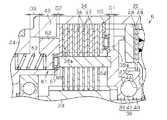
図2に示すように、駆動力伝達装置6は、ディファレンシャルキャリヤ12のカップリングケース21内に回転自在に収容された有底筒状のフロントハウジング22と、同フロントハウジング22の筒内に回転自在に同軸配置された軸状のインナシャフト23とを備えている。   As shown in FIG. 2, the driving force transmission device 6 includes a bottomed cylindrical front housing 22 rotatably accommodated in a coupling case 21 of a differential carrier 12, and is rotatable within the cylinder of the front housing 22. And an axial inner shaft 23 arranged coaxially therewith.

第1回転部材としてのフロントハウジング22は、その底部24(同図中、左側)がカップリングケース21外部に露出された状態で、ボール軸受25により回転自在に支承されるとともに、その開口端26には、環状のリヤハウジング27が嵌着されている。また、第2回転部材としてのインナシャフト23は、リヤハウジング27の内周に設けられたニードル軸受28及びフロントハウジング22の筒内に設けられたボール軸受29により回転自在に支承されている。そして、フロントハウジング22の筒内は、同フロントハウジング22とリヤハウジング27との嵌合部、及びリヤハウジング27の内周とインナシャフト23の外周との間に設けられたシール部材30,31により封止され、その筒内には潤滑油が収容されている。   The front housing 22 as a first rotating member is rotatably supported by a ball bearing 25 with its bottom 24 (left side in the figure) exposed to the outside of the coupling case 21 and its open end 26. A ring-shaped rear housing 27 is fitted into the housing. The inner shaft 23 as the second rotating member is rotatably supported by a needle bearing 28 provided on the inner periphery of the rear housing 27 and a ball bearing 29 provided in a cylinder of the front housing 22. The cylinder of the front housing 22 is fitted by a fitting portion between the front housing 22 and the rear housing 27 and seal members 30 and 31 provided between the inner periphery of the rear housing 27 and the outer periphery of the inner shaft 23. Sealed and lubricating oil is contained in the cylinder.

なお、フロントハウジング22の底部24は、プロペラシャフト5に設けられたフランジ部(図示略)と、ボルト32によって連結される。これにより、フロントハウジング22は、駆動源であるエンジン2の発生するトルクの入力により回転する。また、インナシャフト23における上記ニードル軸受28に支承された側の軸端(同図中、右側)の内周には、ピニオンシャフト7との連結部(スプライン嵌合部)33が形成されている。従って、駆動力伝達装置6は車両1に搭載された状態において、フロントハウジング22は主駆動輪である前輪10f側と連結され、インナシャフト23は補助駆動輪である後輪10r側と連結されるようなっている。   The bottom portion 24 of the front housing 22 is connected to a flange portion (not shown) provided on the propeller shaft 5 by a bolt 32. Thereby, the front housing 22 rotates by the input of the torque which the engine 2 which is a drive source generate | occur | produces. Further, a connecting portion (spline fitting portion) 33 with the pinion shaft 7 is formed on the inner periphery of the shaft end (right side in the figure) of the inner shaft 23 supported by the needle bearing 28. . Therefore, when the driving force transmission device 6 is mounted on the vehicle 1, the front housing 22 is connected to the front wheel 10f side which is the main driving wheel, and the inner shaft 23 is connected to the rear wheel 10r side which is the auxiliary driving wheel. It is like that.

また、フロントハウジング22の筒内には、フロントハウジング22とインナシャフト23とをトルク伝達可能に連結可能なメインクラッチ34が設けられるとともに、メインクラッチ34の軸方向リヤハウジング27側にはパイロットクラッチ35が並置されている。そして、これらメインクラッチ34とパイロットクラッチ35との間にカム機構36が設けられている。   A main clutch 34 is provided in the cylinder of the front housing 22 so that the front housing 22 and the inner shaft 23 can be connected to transmit torque, and a pilot clutch 35 is provided on the axial rear housing 27 side of the main clutch 34. Are juxtaposed. A cam mechanism 36 is provided between the main clutch 34 and the pilot clutch 35.

クラッチ機構としてのメインクラッチ34には、軸方向に移動可能に設けられた複数のアウタクラッチプレート37及びインナクラッチプレート38を交互に配置してなる多板式の摩擦クラッチが採用されている。具体的には、各アウタクラッチプレート37はフロントハウジング22の内周にスプライン嵌合され、各インナクラッチプレート38はインナシャフト23の外周にスプライン嵌合されることにより、それぞれ軸方向に移動可能、且つ対応するフロントハウジング22又はインナシャフト23と一体回転可能に設けられている。メインクラッチ34は、これら各アウタクラッチプレート37及びインナクラッチプレート38が軸方向に押圧され、互いに摩擦係合することにより、フロントハウジング22とインナシャフト23とをトルク伝達可能に連結するようになっている。そして、フロントハウジング22とインナシャフト23との間の伝達トルクは、各アウタクラッチプレート37及びインナクラッチプレート38の摩擦係合力、即ち軸方向の押圧力に応じて変化する。本実施形態では、メインクラッチ34は、軸方向両端側にアウタクラッチプレート37が配置されて構成されている。   The main clutch 34 as a clutch mechanism employs a multi-plate friction clutch in which a plurality of outer clutch plates 37 and inner clutch plates 38 provided so as to be movable in the axial direction are alternately arranged. Specifically, each outer clutch plate 37 is spline-fitted to the inner periphery of the front housing 22, and each inner clutch plate 38 is spline-fitted to the outer periphery of the inner shaft 23 to be movable in the axial direction. And it is provided so as to be able to rotate integrally with the corresponding front housing 22 or inner shaft 23. In the main clutch 34, the outer clutch plate 37 and the inner clutch plate 38 are pressed in the axial direction and frictionally engaged with each other, thereby connecting the front housing 22 and the inner shaft 23 so as to transmit torque. Yes. The transmission torque between the front housing 22 and the inner shaft 23 changes according to the frictional engagement force between the outer clutch plates 37 and the inner clutch plates 38, that is, the axial pressing force. In the present embodiment, the main clutch 34 is configured by disposing outer clutch plates 37 on both ends in the axial direction.

カム機構36は、インナシャフト23の外周にスプライン嵌合されることにより同インナシャフト23と一体回転可能且つ軸方向に移動可能に設けられたメインカム39と、インナシャフト23に回転自在に支承されたパイロットカム40と、パイロットカム40とメインカム39との間に介在されたカムフォロア41とを備えてなる。第1の押圧部材としてのメインカム39及びパイロットカム40は共に円環状に形成され、メインカム39はメインクラッチ34側に、パイロットカム40はリヤハウジング27側に配置されている。メインカム39は、インナシャフト23のスプライン溝のパイロットクラッチ35側にスプライン嵌合している。また、パイロットカム40は、リヤハウジング27との間に設けられたニードル軸受42に当接しており、リヤハウジング27と一定の間隔を保持して相対回転可能に支持されている。   The cam mechanism 36 is rotatably supported by the inner shaft 23 and the main cam 39 provided so as to be integrally rotatable with the inner shaft 23 by being spline fitted to the outer periphery of the inner shaft 23 and to be movable in the axial direction. A pilot cam 40 and a cam follower 41 interposed between the pilot cam 40 and the main cam 39 are provided. Both the main cam 39 and the pilot cam 40 as the first pressing member are formed in an annular shape. The main cam 39 is disposed on the main clutch 34 side, and the pilot cam 40 is disposed on the rear housing 27 side. The main cam 39 is spline-fitted to the pilot clutch 35 side of the spline groove of the inner shaft 23. Further, the pilot cam 40 is in contact with a needle bearing 42 provided between the pilot cam 40 and the rear cam 27, and is supported so as to be relatively rotatable with a predetermined distance from the rear housing 27.

メインカム39及びパイロットカム40の各対向面には、周方向に対して傾斜する複数のカム溝43,44(図3参照)が互いに対向するように形成されており、カムフォロア41は、これら対向する各カム溝43,44内に配置された状態でメインカム39及びパイロットカム40により挟持されている。なお、カム溝43,44は断面U字状に形成され、周方向中央から周方向両端側に向かうにつれてその深さが浅くなるように形成されている。そして、カム機構36は、メインカム39とパイロットカム40とが相対回転することにより、カムフォロア41がカム溝43,44内で転動してメインカム39とパイロットカム40とが離間、即ちメインカム39がメインクラッチ34側に軸方向移動するようになっている。   A plurality of cam grooves 43 and 44 (see FIG. 3) inclined with respect to the circumferential direction are formed on the opposing surfaces of the main cam 39 and the pilot cam 40 so as to oppose each other, and the cam follower 41 opposes each other. It is sandwiched between the main cam 39 and the pilot cam 40 in a state of being arranged in each cam groove 43, 44. The cam grooves 43 and 44 are formed in a U-shaped cross section, and are formed so that the depth becomes shallower from the center in the circumferential direction toward both ends in the circumferential direction. In the cam mechanism 36, when the main cam 39 and the pilot cam 40 rotate relative to each other, the cam follower 41 rolls in the cam grooves 43 and 44 so that the main cam 39 and the pilot cam 40 are separated, that is, the main cam 39 is the main cam 39. It moves in the axial direction toward the clutch 34.

本実施形態では、メインカム39のメインクラッチ34との対向面における径方向外側には、段差部39aが形成されて径方向内側よりも肉薄になっている。この段差部39aには、スラストベアリング45が設けられており、メインカム39は該スラストベアリング45を介してアウタクラッチプレート37を押圧するようになっている。これにより、メインカム39は、アウタクラッチプレート37との間の相対回転可能を許容しつつ、該アウタクラッチプレート37を押圧するようになっている。そして、メインクラッチ34は、メインカム39に押圧されることで、底部24側に配置されたアウタクラッチプレート37が底部24の外周縁から軸方向に延出形成された当接部46に当接し、メインカム39と当接部46との間に挟み込まれて摩擦係合するようになっている。   In the present embodiment, a step portion 39a is formed on the radially outer side of the surface of the main cam 39 facing the main clutch 34, and is thinner than the radially inner side. A thrust bearing 45 is provided at the stepped portion 39 a, and the main cam 39 presses the outer clutch plate 37 through the thrust bearing 45. Thus, the main cam 39 presses the outer clutch plate 37 while allowing relative rotation between the main cam 39 and the outer clutch plate 37. When the main clutch 34 is pressed by the main cam 39, the outer clutch plate 37 disposed on the bottom 24 side comes into contact with a contact portion 46 formed to extend from the outer peripheral edge of the bottom 24 in the axial direction, It is sandwiched between the main cam 39 and the contact portion 46 so as to be frictionally engaged.

パイロットクラッチ35には、上記メインクラッチ34と同様に、軸方向に移動可能に設けられた複数のアウタクラッチプレート48及びインナクラッチプレート49を交互に配置してなる多板式の摩擦クラッチが採用されている。具体的には、各アウタクラッチプレート48は、フロントハウジング22の内周にスプライン嵌合され、インナクラッチプレート49はパイロットカム40の外周にスプライン嵌合されることにより、それぞれ軸方向に移動可能、且つ対応するフロントハウジング22又はパイロットカム40と一体回転可能に設けられている。そして、パイロットクラッチ35は、これら各アウタクラッチプレート48及びインナクラッチプレート49が軸方向に押圧され、互いに摩擦係合することにより、フロントハウジング22とパイロットカム40とをトルク伝達可能に連結するようになっている。   Like the main clutch 34, the pilot clutch 35 employs a multi-plate friction clutch in which a plurality of outer clutch plates 48 and inner clutch plates 49 that are provided so as to be movable in the axial direction are alternately arranged. Yes. Specifically, each outer clutch plate 48 is spline-fitted to the inner periphery of the front housing 22, and the inner clutch plate 49 is spline-fitted to the outer periphery of the pilot cam 40, thereby moving in the axial direction. And it is provided so as to be able to rotate integrally with the corresponding front housing 22 or pilot cam 40. The pilot clutch 35 is configured such that the outer clutch plate 48 and the inner clutch plate 49 are pressed in the axial direction and frictionally engaged with each other, thereby connecting the front housing 22 and the pilot cam 40 so as to transmit torque. It has become.

即ち、メインカム39との間にカムフォロア41を挟持したパイロットカム40は、パイロットクラッチ35の非作動時、メインカム39、即ちインナシャフト23とともに一体回転し、フロントハウジング22とパイロットカム40との間には、フロントハウジング22とインナシャフト23との回転差に相当する回転差が生じている。そして、パイロットクラッチ35は、その作動により、フロントハウジング22とパイロットカム40とをトルク伝達可能に連結することで、フロントハウジング22とインナシャフト23(パイロットカム40)との回転差に基づくトルクをカム機構36に伝達するようになっている。   That is, the pilot cam 40 with the cam follower 41 sandwiched between the main cam 39 rotates together with the main cam 39, that is, the inner shaft 23, when the pilot clutch 35 is not in operation, and between the front housing 22 and the pilot cam 40. A rotation difference corresponding to the rotation difference between the front housing 22 and the inner shaft 23 is generated. The pilot clutch 35 is operated to connect the front housing 22 and the pilot cam 40 so as to be able to transmit torque, thereby camming torque based on the rotational difference between the front housing 22 and the inner shaft 23 (pilot cam 40). It is transmitted to the mechanism 36.

つまり、駆動力伝達装置6では、パイロットクラッチ35の作動により、フロントハウジング22とインナシャフト23との回転差に基づくトルクがカム機構36に伝達され、カム機構36は、そのトルクにより生ずるメインカム39とパイロットカム40との回転差に基づいて同メインカム39を軸方向メインクラッチ34側に移動させる。即ち、カム機構36は、パイロットクラッチ35を介して伝達されたフロントハウジング22とインナシャフト23との回転差に基づくトルクを軸方向の押圧力に変換し、かつ増幅する。そして、そのメインカム39がメインクラッチ34を押圧することにより、同メインクラッチ34が底部24との間に挟み込まれて摩擦係合する、即ちフロントハウジング22とインナシャフト23とがトルク伝達可能に連結されるようになっている。従って、本実施形態では、パイロットクラッチ35及びカム機構36により押圧力発生手段が構成される。   That is, in the driving force transmission device 6, the torque based on the rotational difference between the front housing 22 and the inner shaft 23 is transmitted to the cam mechanism 36 by the operation of the pilot clutch 35, and the cam mechanism 36 is connected to the main cam 39 generated by the torque. Based on the rotational difference from the pilot cam 40, the main cam 39 is moved to the axial main clutch 34 side. That is, the cam mechanism 36 converts the torque based on the rotational difference between the front housing 22 and the inner shaft 23 transmitted through the pilot clutch 35 into an axial pressing force and amplifies it. When the main cam 39 presses the main clutch 34, the main clutch 34 is sandwiched between the bottom portion 24 and frictionally engaged, that is, the front housing 22 and the inner shaft 23 are coupled so as to transmit torque. It has become so. Therefore, in the present embodiment, the pilot clutch 35 and the cam mechanism 36 constitute a pressing force generating means.

パイロットクラッチ35は、電磁石50を駆動源とする電磁クラッチとして構成されている。具体的には、リヤハウジング27には、フロントハウジング22の筒外(反フロントハウジング22側、図2中右側)に開口する環状溝51が形成されており、電磁石50は、この環状溝51内に収容されている。電磁石50には、駆動力伝達装置6の外部に設けられたECU11から電源線52を介して駆動電流が供給される。なお、リヤハウジング27には、その内周部から軸方向、反フロントハウジング22側に延びる円筒部27aが設けられており、電磁石50は、この円筒部27aに設けられたボール軸受53によりリヤハウジング27(及びフロントハウジング22)と相対回転可能に支承されている。   The pilot clutch 35 is configured as an electromagnetic clutch using the electromagnet 50 as a drive source. Specifically, the rear housing 27 is formed with an annular groove 51 that opens to the outside of the front housing 22 (on the side opposite to the front housing 22, the right side in FIG. 2). Is housed in. A driving current is supplied to the electromagnet 50 from the ECU 11 provided outside the driving force transmission device 6 through the power line 52. The rear housing 27 is provided with a cylindrical portion 27a extending axially from the inner peripheral portion thereof toward the front housing 22 side. The electromagnet 50 is connected to the rear housing by a ball bearing 53 provided on the cylindrical portion 27a. 27 (and the front housing 22) are rotatably supported.

また、フロントハウジング22の筒内には、円環状に形成されたアーマチャ54が、同アーマチャ54とリヤハウジング27との間に上記アウタクラッチプレート48及びインナクラッチプレート49を挟む位置において、軸方向に摺動可能にスプライン嵌合されている。そして、パイロットクラッチ35は、このアーマチャ54が、電磁石50の電磁力に吸引され、リヤハウジング27との間に各アウタクラッチプレート48及びインナクラッチプレート49を挟み込むように移動することにより、該各アウタクラッチプレート48及びインナクラッチプレート49が摩擦係合するようになっている。   Further, in the cylinder of the front housing 22, an annular armature 54 is arranged in the axial direction at a position where the outer clutch plate 48 and the inner clutch plate 49 are sandwiched between the armature 54 and the rear housing 27. The spline is slidably fitted. The pilot clutch 35 is attracted to the electromagnetic force of the electromagnet 50 and moves so that the outer clutch plates 48 and the inner clutch plates 49 are sandwiched between the armature 54 and the rear housing 27, thereby The clutch plate 48 and the inner clutch plate 49 are frictionally engaged.

このように、駆動力伝達装置6は、電磁石50に対する電流供給を通じてパイロットクラッチ35の作動を制御することが可能である。そして、このパイロットクラッチ35の作動を通じてメインクラッチ34の作動、即ち、フロントハウジング22とインナシャフト23との間で伝達可能なトルクを自在に制御可能な構成となっている。   As described above, the driving force transmission device 6 can control the operation of the pilot clutch 35 through the current supply to the electromagnet 50. The operation of the main clutch 34, that is, the torque that can be transmitted between the front housing 22 and the inner shaft 23 can be freely controlled through the operation of the pilot clutch 35.

次に、メインクラッチ34をパイロットクラッチ35の非作動時に摩擦係合させるプレトルク機構について説明する。
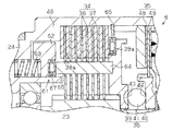
駆動力伝達装置6は、パイロットクラッチ35の非作動時にメインクラッチ34に押圧力を付与して摩擦係合させるとともに、メインカム39がメインクラッチ34に接近するにつれてメインクラッチ34に付与する押圧力を減少させるプレトルク機構61を備えている。本実施形態では、図3に示すように、プレトルク機構61は、メインクラッチ34をメインカム39の軸方向反対側から押圧する第2の押圧部材としてのピストン62と、ピストン62を付勢する弾性部材63と、メインカム39とピストン62とを連動して移動させる連動部材64とを備えている。
Next, a pre-torque mechanism that frictionally engages the main clutch 34 when the pilot clutch 35 is not operated will be described.
The driving force transmission device 6 applies a pressing force to the main clutch 34 and frictionally engages the pilot clutch 35 when the pilot clutch 35 is not operated, and reduces the pressing force applied to the main clutch 34 as the main cam 39 approaches the main clutch 34. A pre-torque mechanism 61 is provided. In the present embodiment, as shown in FIG. 3, the pre-torque mechanism 61 includes a piston 62 as a second pressing member that presses the main clutch 34 from the axially opposite side of the main cam 39, and an elastic member that biases the piston 62. 63, and an interlocking member 64 that moves the main cam 39 and the piston 62 in an interlocking manner.

詳述すると、ピストン62は、円環状に形成されるとともに当接部46の内周側に配置されている。弾性部材63は、底部24とピストン62との間に設けられている。なお、本実施形態では、弾性部材63は、例えばコイルスプリングからなり、周方向に等間隔を空けて複数(例えば4つ)設けられている。また、フロントハウジング22の内周には、ピストン62との間にメインクラッチ34を挟んで配置される止め輪65設けられている。そして、メインクラッチ34は、ピストン62に押圧されることで、該ピストン62と止め輪65との間に挟み込まれて摩擦係合するようになっている。   More specifically, the piston 62 is formed in an annular shape and is disposed on the inner peripheral side of the contact portion 46. The elastic member 63 is provided between the bottom 24 and the piston 62. In the present embodiment, the elastic member 63 is formed of, for example, a coil spring, and a plurality (for example, four) of elastic members 63 are provided at equal intervals in the circumferential direction. A retaining ring 65 is provided on the inner periphery of the front housing 22 with the main clutch 34 interposed between the piston 62 and the piston 62. The main clutch 34 is pressed by the piston 62 so as to be sandwiched between the piston 62 and the retaining ring 65 to be frictionally engaged.

また、減少手段としての連動部材64は、メインカム39及びピストン62の何れか一方の軸方向移動により、メインカム39及びピストン62の何れか他方が連動して移動するように、これらメインカム39とピストン62とを連結している。具体的には、インナクラッチプレート38には、該各インナクラッチプレート38におけるアウタクラッチプレート37と摺動する摺動部38aの内周側に軸方向に沿った貫通孔66が形成されている。貫通孔66は、周方向に等間隔を空けて複数(本実施形態では、4つ)形成され、各インナクラッチプレート38は、各貫通孔66がそれぞれ同軸上に位置するように配置されている。連動部材64は、柱状に形成されるとともに、その基端(図3における右側)がメインカム39における貫通孔66と対応する位置に埋設されて固定されている。そして、連動部材64は各貫通孔66に挿通され、その先端がスラストベアリング67を介してピストン62に当接している。これにより、連動部材64(メインカム39)は、ピストン62との間の相対回転可能を許容しつつ、該ピストン62を押圧するようになっている。さらに、本実施形態では、連動部材64は、例えば鉄、ステンレスや樹脂等の剛性体からなり、メインカム39又はピストンに押圧されても変形しないようになっている。   In addition, the interlocking member 64 as a reducing means is configured such that either the main cam 39 or the piston 62 moves in conjunction with the axial movement of either the main cam 39 or the piston 62. Are linked. Specifically, the inner clutch plate 38 is formed with a through-hole 66 along the axial direction on the inner peripheral side of the sliding portion 38 a that slides with the outer clutch plate 37 in each inner clutch plate 38. A plurality of through holes 66 are formed at equal intervals in the circumferential direction (four in this embodiment), and each inner clutch plate 38 is disposed so that each through hole 66 is coaxially positioned. . The interlocking member 64 is formed in a columnar shape, and its base end (right side in FIG. 3) is embedded and fixed at a position corresponding to the through hole 66 in the main cam 39. The interlocking member 64 is inserted into each through hole 66, and the tip thereof is in contact with the piston 62 via the thrust bearing 67. As a result, the interlocking member 64 (main cam 39) presses the piston 62 while allowing relative rotation with the piston 62. Furthermore, in this embodiment, the interlocking member 64 is made of a rigid body such as iron, stainless steel, or resin, and is not deformed even when pressed by the main cam 39 or the piston.

そして、パイロットクラッチ35の非作動時において、メインカム39とカム機構36側に配置されたアウタクラッチプレート37(メインクラッチ34)との間には、第1の隙間D1が形成されるようになっている。即ち、メインカム39がメインクラッチ34に押圧力を付与するまでに必要な軸方向の移動距離が第1の隙間D1となっている。また、パイロットクラッチ35の非作動時において、底部24側に配置されたアウタクラッチプレート37(メインクラッチ34)と当接部46との間には、第1の隙間D1よりも小さい第2の隙間D2が形成されるようになっている。即ち、当接部46にメインクラッチ34を介してメインカム39の押圧力が作用するまでに必要なメインクラッチ34の移動距離が第2の隙間D2となっている。さらに、ピストン62と底部24との間には、第1の隙間D1よりも大きな第3の隙間D3が形成されるようになっている。即ち、ピストン62が底部24に当接するまでの軸方向距離が第3の隙間D3となっている。そして、弾性部材63は第1の隙間D1よりも大きく弾性変形可能になっている。   When the pilot clutch 35 is not operated, a first gap D1 is formed between the main cam 39 and the outer clutch plate 37 (main clutch 34) disposed on the cam mechanism 36 side. Yes. That is, the axial movement distance required until the main cam 39 applies a pressing force to the main clutch 34 is the first gap D1. Further, when the pilot clutch 35 is not in operation, a second clearance smaller than the first clearance D1 is provided between the outer clutch plate 37 (main clutch 34) disposed on the bottom 24 side and the contact portion 46. D2 is formed. That is, the moving distance of the main clutch 34 required until the pressing force of the main cam 39 acts on the contact portion 46 via the main clutch 34 is the second gap D2. Further, a third gap D3 larger than the first gap D1 is formed between the piston 62 and the bottom 24. That is, the axial distance until the piston 62 contacts the bottom 24 is the third gap D3. The elastic member 63 is elastically deformable to be larger than the first gap D1.

次に、プレトルク機構61の作用について説明する。
上述したように、パイロットクラッチ35の非作動時には、メインクラッチ34は、ピストン62に押圧されて摩擦係合しており、フロントハウジング22からインナシャフトへ所定のトルクが伝達可能になっている。
Next, the operation of the pre-torque mechanism 61 will be described.
As described above, when the pilot clutch 35 is not in operation, the main clutch 34 is pressed and frictionally engaged with the piston 62 so that a predetermined torque can be transmitted from the front housing 22 to the inner shaft.

一方、ECU11から電磁石50への電流供給を開始すると、パイロットクラッチ35が作動し、フロントハウジング22とインナシャフト23との回転差に基づくトルクがパイロットクラッチ35の摩擦係合力に応じてカム機構36に伝達され、メインカム39が軸方向に移動し始める。そして、電磁石50に供給される電流の増加に伴いメインカム39の軸方向移動量が増加すると、メインカム39は、第1の隙間D1が無くなるまでの間は、連動部材64を介してピストン62のみを弾性部材63の付勢方向と反対方向に押圧する。そのため、ピストン62がメインクラッチ34に付与する押圧力が減少し、メインクラッチ34の摩擦係合力が小さくなってメインクラッチ34のトルク伝達容量が小さくなる。   On the other hand, when current supply from the ECU 11 to the electromagnet 50 is started, the pilot clutch 35 is operated, and torque based on the rotational difference between the front housing 22 and the inner shaft 23 is applied to the cam mechanism 36 according to the frictional engagement force of the pilot clutch 35. Then, the main cam 39 starts to move in the axial direction. When the amount of axial movement of the main cam 39 increases as the current supplied to the electromagnet 50 increases, the main cam 39 moves only the piston 62 via the interlocking member 64 until the first gap D1 disappears. The elastic member 63 is pressed in the direction opposite to the urging direction. Therefore, the pressing force applied by the piston 62 to the main clutch 34 is reduced, the friction engagement force of the main clutch 34 is reduced, and the torque transmission capacity of the main clutch 34 is reduced.

そして、メインカム39が第2の隙間D2以上、第1の隙間D1以下だけ軸方向に移動した状態(図4参照)では、メインクラッチ34はピストン62によって押圧されず、且つメインカム39によっても押圧されないため、メインクラッチ34のトルク伝達容量が0になる。なお、図4はメインカム39が第1の隙間D1以下だけ軸方向に移動した状態である。従って、駆動力伝達装置6のトルク伝達容量は、パイロットクラッチ35のトルク伝達容量に応じた値になる。そして、図4に示す状態から、電磁石50に供給する電流をさらに増加すると、図5に示すように、メインクラッチ34はメインカム39により押圧されて再び摩擦係合し、メインカム39の軸方向移動量に応じてメインクラッチ34のトルク伝達容量が大きくなる。   In a state where the main cam 39 is moved in the axial direction by not less than the second gap D2 and not more than the first gap D1 (see FIG. 4), the main clutch 34 is not pressed by the piston 62 and is not pressed by the main cam 39. Therefore, the torque transmission capacity of the main clutch 34 becomes zero. FIG. 4 shows a state in which the main cam 39 is moved in the axial direction by the first gap D1 or less. Accordingly, the torque transmission capacity of the driving force transmission device 6 is a value corresponding to the torque transmission capacity of the pilot clutch 35. When the current supplied to the electromagnet 50 is further increased from the state shown in FIG. 4, the main clutch 34 is pressed by the main cam 39 and frictionally engaged again, as shown in FIG. Accordingly, the torque transmission capacity of the main clutch 34 increases.

従って、本実施形態の駆動力伝達装置6は、図6に示すように、電磁石50に供給される電流に応じてトルク伝達容量を変更可能に構成されている。具体的には、メインクラッチ34のトルク伝達容量は、一点鎖線で示すように、電流の増加に応じて一旦下がり、その後増加する。また、パイロットクラッチ35のトルク伝達容量は、二点鎖線で示すように、電流の増加に応じて単調増加する。従って、駆動力伝達装置6のトルク伝達容量は、太線で示すように、電流の増加に応じて一旦下がり、その後増加するようになっている。そのため、例えば車両1の発進時にスリップが発生する場合等のように前輪10fと後輪10rとの間の車輪速差の発生初期においても、ピストン62によりメインクラッチ34にプレトルクが付与されているため、後輪10rには所定のトルクが配分され、スリップが大きくなることを防止してトラクション性能の向上を図ることができる。また、車両1の旋回半径が小さくなる場合には、メインカム39が第2の隙間D2以上第1の隙間D1以下だけ軸方向に移動するように電流を供給することで、駆動力伝達装置6のトルク伝達容量を小さくし、例えば車両1の旋回半径が小さい場合にタイトコーナブレーキング現象の発生を防止して車両1の走行安定性の向上を図ることができる。   Therefore, the driving force transmission device 6 of the present embodiment is configured to be able to change the torque transmission capacity in accordance with the current supplied to the electromagnet 50, as shown in FIG. Specifically, the torque transmission capacity of the main clutch 34 temporarily decreases as the current increases, and then increases, as indicated by the alternate long and short dash line. Further, the torque transmission capacity of the pilot clutch 35 monotonously increases as the current increases, as indicated by a two-dot chain line. Therefore, the torque transmission capacity of the driving force transmission device 6 is once lowered and increased thereafter as the current increases, as shown by the thick line. For this reason, pre-torque is applied to the main clutch 34 by the piston 62 even at the initial stage of occurrence of the wheel speed difference between the front wheel 10f and the rear wheel 10r, for example, when slip occurs when the vehicle 1 starts. A predetermined torque is distributed to the rear wheel 10r, and an increase in slip can be prevented to improve traction performance. Further, when the turning radius of the vehicle 1 is small, the current is supplied so that the main cam 39 moves in the axial direction by the second gap D2 or more and the first gap D1 or less, so that the driving force transmission device 6 For example, when the torque transmission capacity is reduced and, for example, the turning radius of the vehicle 1 is small, the tight corner braking phenomenon can be prevented and the running stability of the vehicle 1 can be improved.

以上記述したように、本実施形態によれば、以下の効果を奏する。
(1)駆動力伝達装置6は、メインカム39の軸方向反対側からメインクラッチ34を軸方向に押圧するピストン62と、カム機構36により発生する押圧力の増加に基づいてピストン62がメインクラッチ34へ付与する押圧力を減少させる連動部材64とを備えた。そのため、パイロットクラッチ35の非作動時に、メインクラッチ34はピストン62によって押圧されることで摩擦係合し、所定のトルクを伝達可能になる。従って、例えば車両1の発進時にスリップが発生する場合等のように車輪速差の発生初期においても、後輪10rに所定のトルクが配分され、スリップが大きくなることを防止してトラクション性能の向上を図ることができる。また、連動部材64により、カム機構36にて発生する押圧力の増加に基づいてピストン62がメインクラッチ34へ付与する押圧力を減少させることで、メインクラッチ34の摩擦係合力を減少させて、例えば車両1の旋回半径が小さい場合にタイトコーナブレーキング現象の発生を防止し、車両1の走行安定性の向上を図ることができる。
As described above, according to the present embodiment, the following effects can be obtained.
(1) The driving force transmission device 6 includes a piston 62 that presses the main clutch 34 in the axial direction from the opposite side of the main cam 39 in the axial direction, and the piston 62 that is connected to the main clutch 34 based on an increase in pressing force generated by the cam mechanism 36. And an interlocking member 64 that reduces the pressing force applied to the. Therefore, when the pilot clutch 35 is not operated, the main clutch 34 is frictionally engaged by being pressed by the piston 62 and can transmit a predetermined torque. Therefore, for example, when a slip occurs when the vehicle 1 starts, a predetermined torque is distributed to the rear wheel 10r even in the initial generation of the wheel speed difference, thereby preventing the slip from increasing and improving the traction performance. Can be achieved. In addition, the interlocking member 64 reduces the frictional force of the main clutch 34 by reducing the pressing force applied to the main clutch 34 by the piston 62 based on the increase in the pressing force generated by the cam mechanism 36. For example, when the turning radius of the vehicle 1 is small, the occurrence of a tight corner braking phenomenon can be prevented and the running stability of the vehicle 1 can be improved.

(2)インナクラッチプレート38における摺動部38aの内周側に貫通孔66を形成した。そして、連動部材64は、その基端がメインカム39における貫通孔66と対応する位置に固定され、各貫通孔66に挿通されてその先端がスラストベアリング67を介してピストン62に当接するようにした。従って、メインカム39がメインクラッチ34側に軸方向移動することで、ピストン62がメインクラッチ34に付与する押圧力を減少させることができる。   (2) A through hole 66 is formed on the inner peripheral side of the sliding portion 38a in the inner clutch plate 38. The interlocking member 64 has a base end fixed at a position corresponding to the through hole 66 in the main cam 39, and is inserted into each through hole 66 so that a tip thereof contacts the piston 62 via a thrust bearing 67. . Accordingly, the main cam 39 moves in the axial direction toward the main clutch 34, whereby the pressing force applied by the piston 62 to the main clutch 34 can be reduced.

(3)フロントハウジング22を有底筒状に形成し、該フロントハウジング22の底部24の外周縁に、メインカム39に押圧されたメインクラッチ34が当接する当接部46を軸方向に延出形成した。そして、ピストン62を、当接部46の内周側に配置し、該ピストン62と底部24との間に設けた弾性部材63によりメインクラッチ34側に付勢されるようにした。そのため、当接部46の内周側にピストン62が配置されるため、駆動力伝達装置6の大型化を防止できる。また、ピストン62は、底部24との間に設けられた弾性部材63により押圧されるため、簡単な構成でピストン62を押圧することができる。   (3) The front housing 22 is formed in a bottomed cylindrical shape, and an abutting portion 46 is formed in the outer peripheral edge of the bottom portion 24 of the front housing 22 so as to abut the main clutch 34 pressed by the main cam 39 in the axial direction. did. The piston 62 is disposed on the inner peripheral side of the contact portion 46 and is urged toward the main clutch 34 by an elastic member 63 provided between the piston 62 and the bottom portion 24. Therefore, since the piston 62 is disposed on the inner peripheral side of the contact portion 46, the driving force transmission device 6 can be prevented from being enlarged. Moreover, since the piston 62 is pressed by the elastic member 63 provided between the bottom part 24, the piston 62 can be pressed with a simple configuration.

(4)パイロットクラッチ35の非作動時に、メインカム39とメインクラッチ34との間に第1の隙間D1を形成し、当接部46とメインクラッチ34との間に第1の隙間D1よりも小さい第2の隙間D2を形成した。また、ピストン62と底部24との間に第1の隙間D1よりも大きな第3の隙間D3を形成し、弾性部材63を第1の隙間D1よりも大きく弾性変形可能に構成した。そのため、メインカム39の軸方向移動により、ピストン62がメインクラッチ34に付与する押圧力を0にすることができるため、確実にタイトコーナブレーキング現象の発生を防止できる。   (4) When the pilot clutch 35 is not operated, the first gap D1 is formed between the main cam 39 and the main clutch 34, and is smaller than the first gap D1 between the contact portion 46 and the main clutch 34. A second gap D2 was formed. Further, a third gap D3 larger than the first gap D1 is formed between the piston 62 and the bottom 24, and the elastic member 63 is configured to be elastically deformable larger than the first gap D1. Therefore, the axial force of the main cam 39 can reduce the pressing force applied by the piston 62 to the main clutch 34, so that the tight corner braking phenomenon can be reliably prevented.

(5)連動部材64を剛生体により構成したため、メインカム39又はピストン62により押圧されても変形せず、メインカム39とピストン62とが軸方向の相対距離を変えずに軸方向移動する。そのため、メインカム39の軸方向移動に応じてピストン62がメインクラッチ34へ付与する押圧力を、例えば連動部材64を弾性材料により構成した場合に比べ、効率よく減少させることができる。従って、ピストン62がメインクラッチ34に付与する押圧力を減少させるためにメインカム39が軸方向に移動する距離を短くすることが可能になり、駆動力伝達装置6の軸方向の大型化を防止できる。   (5) Since the interlocking member 64 is composed of a rigid body, it does not deform even when pressed by the main cam 39 or the piston 62, and the main cam 39 and the piston 62 move in the axial direction without changing the relative distance in the axial direction. Therefore, the pressing force applied by the piston 62 to the main clutch 34 in accordance with the axial movement of the main cam 39 can be reduced more efficiently than when the interlocking member 64 is made of an elastic material, for example. Accordingly, it is possible to reduce the distance that the main cam 39 moves in the axial direction in order to reduce the pressing force applied by the piston 62 to the main clutch 34, and it is possible to prevent the driving force transmission device 6 from being enlarged in the axial direction. .

なお、上記実施形態は、以下の態様で実施してもよい。
・上記実施形態では、連動部材64は、メインカム39に埋設して固定されたが、これに限らず、メインカム39に固定されていればよく、例えばメインカム39と連動部材64とを一体に形成してもよい。
In addition, you may implement the said embodiment in the following aspects.
In the above embodiment, the interlocking member 64 is embedded and fixed in the main cam 39. However, the interlocking member 64 is not limited thereto, and may be fixed to the main cam 39. For example, the main cam 39 and the interlocking member 64 are integrally formed. May be.

・上記実施形態では、連動部材64は、メインカム39に固定されるとともにスラストベアリング67を介してピストン62と当接するようにしたが、これに限らず、連動部材64をピストン62に固定するとともにスラストベアリング67を介してメインカム39に当接するようにしてもよい。   In the above embodiment, the interlocking member 64 is fixed to the main cam 39 and is brought into contact with the piston 62 via the thrust bearing 67. However, the present invention is not limited to this, and the interlocking member 64 is fixed to the piston 62 and the thrust. You may make it contact | abut to the main cam 39 via the bearing 67. FIG.

・上記実施形態では、弾性部材63を周方向に等間隔を空けて複数設けたが、これに限らず、ピストン62と略同径のコイルスプリングを1つ設けてもよい。
・上記実施形態では、パイロットクラッチ35の非作動時において、第2の隙間D2を第1の隙間D1よりも小さくするとともに、第3の隙間D3を第1の隙間D1よりも大きくし、ピストン62をメインカム39の軸方向移動により、第1の隙間D1よりも大きく軸方向、反メインクラッチ34側に移動されるようにした。しかしながら、これに限らず、第2の隙間D2が第1の隙間D1以下であるとともに第3の隙間D3が第1の隙間D1以上であり、メインカム39の軸方向移動により、ピストン62を第1の隙間D1の軸方向距離と同じ距離だけ軸方向、反メインクラッチ34側に移動されるようにすればよい。このようにしても、メインクラッチ34のトルク伝達容量を0にすることができる。
In the above embodiment, a plurality of elastic members 63 are provided at equal intervals in the circumferential direction. However, the present invention is not limited to this, and one coil spring having substantially the same diameter as the piston 62 may be provided.
In the above embodiment, when the pilot clutch 35 is not in operation, the second gap D2 is made smaller than the first gap D1, the third gap D3 is made larger than the first gap D1, and the piston 62 By moving the main cam 39 in the axial direction, the main cam 39 is moved to the side opposite to the main clutch 34 in the axial direction larger than the first gap D1. However, the present invention is not limited to this, and the second gap D2 is equal to or smaller than the first gap D1 and the third gap D3 is equal to or larger than the first gap D1. What is necessary is just to make it move to the direction opposite to the main clutch 34 in the axial direction by the same distance as the axial distance of the gap D1. Even in this case, the torque transmission capacity of the main clutch 34 can be reduced to zero.

また、第2の隙間D2を第1の隙間D1よりも大きくし、ピストン62をメインカム39の軸方向移動により、第2の隙間D2の軸方向距離よりも小さい距離しか軸方向、反メインクラッチ34側に移動されないようにしてもよい。このようにしても、メインクラッチ34のトルク伝達容量を減少させることができる。   Further, the second gap D2 is made larger than the first gap D1, and the piston 62 is moved in the axial direction of the main cam 39, so that the distance between the second gap D2 and the anti-main clutch 34 is smaller than the axial distance of the second gap D2. It may not be moved to the side. Even in this case, the torque transmission capacity of the main clutch 34 can be reduced.

・上記実施形態では、メインクラッチ34の軸方向両端にアウタクラッチプレート37が配置されるようにしたが、これに限らず、軸方向両端にインナクラッチプレートが配置されるようにしてもよい。この場合、底部24側に配置されたインナクラッチプレート38と当接部46及びピストン62との間にスラストベアリングを介在させることが望ましく、スラストベアリング45は設けずともよい。   In the above embodiment, the outer clutch plates 37 are disposed at both axial ends of the main clutch 34. However, the present invention is not limited thereto, and inner clutch plates may be disposed at both axial ends. In this case, it is desirable to interpose a thrust bearing between the inner clutch plate 38 disposed on the bottom 24 side, the contact portion 46 and the piston 62, and the thrust bearing 45 may not be provided.

・上記実施形態では、底部24にピストン62及び弾性部材63を設けたが、これに限らず、インナシャフト23の底部24側端部に径方向外側に延びるフランジ部を形成し、このフランジ部にピストン62及び弾性部材63を設けてもよい。この場合、底部24側に配置されたアウタクラッチプレート37とピストン62との間にスラストベアリングを介在させることが望ましい。   In the above embodiment, the piston 62 and the elastic member 63 are provided on the bottom 24. However, the present invention is not limited to this, and a flange portion extending radially outward is formed at the end of the inner shaft 23 on the bottom 24 side. A piston 62 and an elastic member 63 may be provided. In this case, it is desirable to interpose a thrust bearing between the outer clutch plate 37 and the piston 62 disposed on the bottom 24 side.

・上記実施形態では、駆動力伝達装置6のトルク伝達容量を電磁石50に供給される電流が増加するにつれて、一旦減少し、その後増加するようにしたが、これに限らず、パイロットクラッチ35の非作動時に駆動力伝達装置6のトルク伝達容量が最大になり、電流の増加によってトルク伝達容量が減少のみするようにしてもよい。   In the above-described embodiment, the torque transmission capacity of the driving force transmission device 6 is once decreased and then increased as the current supplied to the electromagnet 50 increases. The torque transmission capacity of the driving force transmission device 6 may be maximized during operation, and the torque transmission capacity may be decreased only by increasing the current.

・上記実施形態では、連動部材64を剛体材料により構成したが、これに限らず、連動部材64をコイルスプリングなどの弾性部材により構成してもよい。
・上記実施形態では、パイロットクラッチ35を電磁クラッチとして構成し、電磁石50に電流を供給したが、これに限らず、油圧によりパイロットクラッチ35を作動させ、油圧バルブに供給する電流を制御することで、伝達トルクの制御を行ってもよい。
In the above embodiment, the interlocking member 64 is made of a rigid material. However, the present invention is not limited to this, and the interlocking member 64 may be made of an elastic member such as a coil spring.
In the above embodiment, the pilot clutch 35 is configured as an electromagnetic clutch and current is supplied to the electromagnet 50. However, the present invention is not limited to this, and the pilot clutch 35 is operated by hydraulic pressure to control the current supplied to the hydraulic valve. The transmission torque may be controlled.

・上記実施形態では、パイロットカム40及びカム機構36により押圧力発生手段を構成したが、これに限らず、例えば油圧によって作動するピストンを第1の押圧部材としてメインクラッチ34を駆動させる駆動力伝達装置に本発明を適用してもよい。   In the above embodiment, the pressing force generating means is configured by the pilot cam 40 and the cam mechanism 36. However, the present invention is not limited to this, and for example, a driving force transmission for driving the main clutch 34 using a piston operated by hydraulic pressure as the first pressing member. The present invention may be applied to an apparatus.

・上記実施形態では、減少手段として連動部材64を用いたが、これに限らず、カム機構36にて発生する押圧力の増加に基づいてピストン62がメインクラッチ34へ付与する押圧力が減少すればよい。例えば、フロントハウジング22の底部24に電磁石を設け、供給される電流に応じてピストン62を吸引するようにしてもよい。   In the above embodiment, the interlocking member 64 is used as the reducing means. However, the present invention is not limited to this, and the pressing force applied to the main clutch 34 by the piston 62 based on the increase in the pressing force generated by the cam mechanism 36 is reduced. That's fine. For example, an electromagnet may be provided on the bottom 24 of the front housing 22 and the piston 62 may be attracted according to the supplied current.

・上記実施形態では、前輪10fを主駆動輪とする車両1に駆動力伝達装置6を搭載したが、これに限らず、後輪10rを主駆動輪とする車両に搭載してもよい。   In the above embodiment, the driving force transmission device 6 is mounted on the vehicle 1 having the front wheel 10f as the main driving wheel.

駆動力伝達装置を備えた車両の概略構成図。The schematic block diagram of the vehicle provided with the driving force transmission apparatus. 駆動力伝達装置の断面図。Sectional drawing of a driving force transmission device. パイロットクラッチの非作動時における駆動力伝達装置の拡大断面図。The expanded sectional view of the driving force transmission device at the time of non-operation of a pilot clutch. パイロットクラッチの作動によりメインクラッチに押圧力が作用していない状態の駆動力伝達装置の拡大断面図。The expanded sectional view of the driving force transmission device in the state where the pressing force is not acting on the main clutch by the operation of the pilot clutch. パイロットクラッチの作動によりメインクラッチがメインカムに押圧された状態の駆動力伝達装置の拡大断面図。The expanded sectional view of the driving force transmission device in the state where the main clutch was pressed by the main cam by the operation of the pilot clutch. 電磁石に供給される電流とトルク伝達容量との関係を示す波形図。The wave form diagram which shows the relationship between the electric current supplied to an electromagnet, and torque transmission capacity.

符号の説明Explanation of symbols

6…駆動力伝達装置、22…フロントハウジング、23…インナシャフト、24…底部、34…メインクラッチ、35…パイロットクラッチ、36…カム機構、37…アウタクラッチプレート、38…インナクラッチプレート、38a…摺動部、39…メインカム、46…当接部、62…ピストン、63…弾性部材、64…連動部材、66…貫通孔、D1…第1の隙間、D2…第2の隙間、D3…第3の隙間。   6 ... Driving force transmission device, 22 ... Front housing, 23 ... Inner shaft, 24 ... Bottom, 34 ... Main clutch, 35 ... Pilot clutch, 36 ... Cam mechanism, 37 ... Outer clutch plate, 38 ... Inner clutch plate, 38a ... Sliding part 39 ... main cam 46 ... abutting part 62 ... piston 63 ... elastic member 64 ... interlocking member 66 ... through hole D1 ... first gap D2 ... second gap D3 ... first 3 gaps.

Claims (5)

円筒状の第1回転部材と、前記第1回転部材内に回転自在に同軸配置された軸状の第2回転部材と、前記第1回転部材と一体回転するアウタクラッチプレート及び前記第2回転部材と一体回転するインナクラッチプレートが交互に配置されたクラッチ機構と、軸方向の押圧力を発生させる押圧力発生手段と、前記押圧力発生手段によって発生された押圧力に応じて軸方向移動し前記クラッチ機構を押圧する第1の押圧部材とを備え、前記第1回転部材と前記第2回転部材との間のトルク伝達容量を変更可能に構成された駆動力伝達装置において、
前記第1の押圧部材の軸方向反対側から前記クラッチ機構を軸方向に押圧する第2の押圧部材と、
前記押圧力発生手段にて発生する押圧力の増加に基づいて前記第2の押圧部材が前記クラッチ機構へ付与する押圧力を減少させる減少手段とを備えたことを特徴とする駆動力伝達装置。
A cylindrical first rotating member, a shaft-like second rotating member coaxially disposed in the first rotating member, an outer clutch plate that rotates integrally with the first rotating member, and the second rotating member And clutch mechanisms in which inner clutch plates that rotate integrally with each other, pressing force generating means for generating axial pressing force, and axial movement according to the pressing force generated by the pressing force generating means A driving force transmission device including a first pressing member that presses the clutch mechanism, and configured to be able to change a torque transmission capacity between the first rotating member and the second rotating member;
A second pressing member that axially presses the clutch mechanism from an axially opposite side of the first pressing member;
A driving force transmission device comprising: a reducing means for reducing the pressing force applied to the clutch mechanism by the second pressing member based on an increase in the pressing force generated by the pressing force generating means.
前記インナクラッチプレートには、該インナクラッチプレートにおける前記アウタクラッチプレートと摺動する摺動部の内周側に貫通孔が形成され、
前記減少手段は、前記貫通孔に挿通され、前記第1の押圧部材及び前記第2の押圧部材の何れか一方の軸方向移動により、前記第1の押圧部材及び前記第2の押圧部材の何れか他方を連動して移動させる連動部材であることを特徴とする請求項1に記載の駆動力伝達装置。
In the inner clutch plate, a through hole is formed on an inner peripheral side of a sliding portion that slides with the outer clutch plate in the inner clutch plate,
The reducing means is inserted through the through-hole, and any one of the first pressing member and the second pressing member is moved in the axial direction of either the first pressing member or the second pressing member. The driving force transmission device according to claim 1, wherein the driving force transmission device is an interlocking member that moves the other interlockingly.
前記第1回転部材は有底筒状に形成され、
前記第1回転部材の底部の外周縁には、前記第1の押圧部材に押圧された前記クラッチ機構が当接する当接部が軸方向に延出形成され、
前記第2の押圧部材は、前記当接部の内周側に配置され、該第2の押圧部材と前記底部との間に設けられた弾性部材により前記クラッチ機構側に付勢されることを特徴とする請求項1又は2に記載の駆動力伝達装置。
The first rotating member is formed in a bottomed cylindrical shape,
On the outer peripheral edge of the bottom portion of the first rotating member, an abutting portion with which the clutch mechanism pressed against the first pressing member abuts is formed extending in the axial direction.
The second pressing member is disposed on the inner peripheral side of the contact portion, and is biased toward the clutch mechanism by an elastic member provided between the second pressing member and the bottom portion. The driving force transmission device according to claim 1 or 2, characterized in that
前記押圧力発生手段の非作動時において、
前記第1の押圧部材と前記クラッチ機構との間には、第1の隙間が形成され、
前記当接部と前記クラッチ機構との間には、前記第1の隙間以下の第2の隙間が形成され、
前記第2の押圧部材と前記底部との間には、前記第1の隙間以上の第3の隙間が形成され、
前記弾性部材は、前記第1の隙間以上に弾性変形可能に構成されたことを特徴とする請求項3に記載の駆動力伝達装置。
When the pressing force generating means is not in operation,
A first gap is formed between the first pressing member and the clutch mechanism,
A second gap that is equal to or smaller than the first gap is formed between the contact portion and the clutch mechanism,
Between the second pressing member and the bottom, a third gap that is equal to or greater than the first gap is formed,
The driving force transmission device according to claim 3, wherein the elastic member is configured to be elastically deformable beyond the first gap.
前記連動部材は、剛性体からなることを特徴とする請求項2〜4のうちの何れか一項に記載の駆動力伝達装置。   The driving force transmission device according to claim 2, wherein the interlocking member is made of a rigid body.
JP2008081150A 2008-03-26 2008-03-26 Drive force transmitting device Pending JP2009236176A (en)

Priority Applications (1)

Application Number Priority Date Filing Date Title
JP2008081150A JP2009236176A (en) 2008-03-26 2008-03-26 Drive force transmitting device

Applications Claiming Priority (1)

Application Number Priority Date Filing Date Title
JP2008081150A JP2009236176A (en) 2008-03-26 2008-03-26 Drive force transmitting device

Publications (1)

Publication Number Publication Date
JP2009236176A true JP2009236176A (en) 2009-10-15

Family

ID=41250382

Family Applications (1)

Application Number Title Priority Date Filing Date
JP2008081150A Pending JP2009236176A (en) 2008-03-26 2008-03-26 Drive force transmitting device

Country Status (1)

Country Link
JP (1) JP2009236176A (en)

Cited By (1)

* Cited by examiner, † Cited by third party
Publication number Priority date Publication date Assignee Title
KR20220097199A (en) * 2020-12-31 2022-07-07 주식회사 카펙발레오 Torque converter for vehilce

Cited By (2)

* Cited by examiner, † Cited by third party
Publication number Priority date Publication date Assignee Title
KR20220097199A (en) * 2020-12-31 2022-07-07 주식회사 카펙발레오 Torque converter for vehilce
KR102594511B1 (en) * 2020-12-31 2023-10-27 주식회사 카펙발레오 Torque converter for vehilce

Similar Documents

Publication Publication Date Title
US10654360B2 (en) Four-wheel drive vehicle and method for controlling the four-wheel drive vehicle
US5720375A (en) Coupling device for use in differential gear devices
US11207979B2 (en) Drive device for vehicle
JP2010096239A (en) Driving force transmitting device
JP2009236176A (en) Drive force transmitting device
JP2011122679A (en) Electromagnetic clutch
JP5504900B2 (en) Cam mechanism and electromagnetic clutch
JP2004187476A (en) Electromagnetic actuator and differential gear employing it
JP5498707B2 (en) Combined differential limiter
US11117465B2 (en) Vehicle driving-force distributing device
JP6269283B2 (en) Vehicle differential
JP2015090166A (en) Drive force transmission device
JP2016142369A (en) Power force disconnecting mechanism
JP2015148280A (en) Multiplate clutch for vehicle
US6708806B2 (en) Power transmission apparatus
JP4192955B2 (en) Driving force transmission device
JP2010006263A (en) Power transmission device and four-wheel drive vehicle using the same
JP2013221541A (en) Driving force transmission device
JP2013245733A (en) Driving force transmission control device
JP2011122680A (en) Electromagnetic clutch
JP2015121279A (en) Driving force transmission device
JP2011256933A (en) Friction transmission structure, friction clutch, and differential lock device
JP2020128771A (en) Drive force transmission device and four-wheel drive vehicle
JP2008248937A (en) Driving force transmission
JP6216653B2 (en) Driving force distribution device