JP2009228564A - Control device for exhaust gas sensor - Google Patents
Control device for exhaust gas sensor Download PDFInfo
- Publication number
- JP2009228564A JP2009228564A JP2008075675A JP2008075675A JP2009228564A JP 2009228564 A JP2009228564 A JP 2009228564A JP 2008075675 A JP2008075675 A JP 2008075675A JP 2008075675 A JP2008075675 A JP 2008075675A JP 2009228564 A JP2009228564 A JP 2009228564A
- Authority
- JP
- Japan
- Prior art keywords
- condensed water
- temperature
- exhaust
- amount
- exhaust gas
- Prior art date
- Legal status (The legal status is an assumption and is not a legal conclusion. Google has not performed a legal analysis and makes no representation as to the accuracy of the status listed.)
- Granted
Links
Images
Classifications
-
- Y02T10/146—
-
- Y02T10/47—
Landscapes
- Combined Controls Of Internal Combustion Engines (AREA)
Abstract
【課題】排気管に溜まる凝縮水の量を計測する器具などを不要にして、排気ガスセンサの損傷防止にかかる製造コストを十分に低減する排気ガスセンサの制御装置を提供する。
【解決手段】排気管壁温推定部が、供給熱量算出マップ、壁温加算値マップ、壁温減算値マップを参照して、排気温度センサから検出された排気温度、エアフロメータから検出されたガス流量、および外気温センサによって検出された外気温から逐次求められる排気管内の推定壁温を算出すると共に排気管壁露点温度算出部は、露点温度算出マップを参照して、ガス流量と燃料重量との空燃比から求まる排気管の露点温度を算出し、凝縮水量推定部は、凝縮水積算量算出マップを参照して、推定壁温と露点温度とから相対壁温を求め、相対壁温およびガス流量から凝縮水積算量を算出し、算出された凝縮水積算量を積算した値を凝縮水の量として推定する。
【選択図】図5There is provided an exhaust gas sensor control apparatus that eliminates the need for an instrument for measuring the amount of condensed water accumulated in an exhaust pipe and sufficiently reduces the manufacturing cost for preventing damage to the exhaust gas sensor.
An exhaust pipe wall temperature estimating unit refers to a supply heat amount calculation map, a wall temperature addition value map, and a wall temperature subtraction value map, and detects an exhaust temperature detected from an exhaust temperature sensor and a gas detected from an air flow meter. The exhaust pipe wall dew point temperature calculation unit calculates the estimated wall temperature in the exhaust pipe obtained sequentially from the flow rate and the outside air temperature detected by the outside air temperature sensor, and the exhaust pipe wall dew point temperature calculation unit refers to the dew point temperature calculation map to calculate the gas flow rate and the fuel weight. The dew point temperature of the exhaust pipe obtained from the air-fuel ratio of the exhaust pipe is calculated, and the condensate amount estimation unit obtains the relative wall temperature from the estimated wall temperature and the dew point temperature with reference to the condensate integrated amount calculation map, and calculates the relative wall temperature and gas. A condensed water integrated amount is calculated from the flow rate, and a value obtained by integrating the calculated condensed water integrated amount is estimated as the amount of condensed water.
[Selection] Figure 5
Description
本発明は、内燃機関の排気管に設けられた排気ガスセンサの制御装置に関する。 The present invention relates to an exhaust gas sensor control device provided in an exhaust pipe of an internal combustion engine.
従来、排気ガスセンサは、車両に搭載された内燃機関としてのエンジンの排気管などに設けられている。このような排気ガスセンサは、排気管を通る排気ガスの濃度を検知し、検知した濃度に応じた電圧を出力するようになっており、ECU(Electronic [or Engine] Control Unit)は、排気ガスセンサから出力された電圧に基づいて排気ガスの空燃比を算出し、算出した排気ガスの空燃比が、触媒で排気ガスを浄化する際の理想的な空燃比になるように、エンジンに与えるガス流量および燃料噴射重量を調整している。 Conventionally, an exhaust gas sensor is provided in an exhaust pipe of an engine as an internal combustion engine mounted on a vehicle. Such an exhaust gas sensor detects the concentration of exhaust gas passing through the exhaust pipe and outputs a voltage corresponding to the detected concentration. The ECU (Electronic [or Engine] Control Unit) Based on the output voltage, the air-fuel ratio of the exhaust gas is calculated, and the gas flow rate given to the engine and the engine so that the calculated air-fuel ratio of the exhaust gas becomes the ideal air-fuel ratio when purifying the exhaust gas with the catalyst. The fuel injection weight is adjusted.
排気ガスセンサは、セラミックなどの材質からなり、一定温度以上になって活性化しないと排ガス成分を検出できないのでヒータを内蔵し、このヒータで活性化するように加熱される。また、冷却されたエンジンの始動時においては、排ガス中の水蒸気の凝縮により排気管内で凝縮水が生じて溜まることがある。凝縮水が溜まると加熱された排気ガスセンサに被ってしまい、排気ガスセンサが損傷してしまう恐れがある。 The exhaust gas sensor is made of a material such as ceramic, and since an exhaust gas component cannot be detected unless it is activated at a certain temperature or higher, a heater is built in and heated to be activated by this heater. In addition, when the cooled engine is started, condensed water may be generated and accumulated in the exhaust pipe due to condensation of water vapor in the exhaust gas. If condensed water accumulates, the exhaust gas sensor is covered with heat, and the exhaust gas sensor may be damaged.
そこで、排気管内で凝縮水が生じたことを検知する装置としては、エンジンから排出された排気ガスが流れる排気管において排気ガスセンサの下流側に窪みをつけて排気管内の水分を滞留させるための水分滞留部と、窪みをつけた水分滞留部に滞留している水分を検出する水分検出手段とを設け、水分検出手段は、水分滞留部に水分が滞留したときに電流が流れるよう2枚の電極および電源を有し、さらに2枚の電極間に流される電流を計測する電流計を備えたものが知られている(例えば、特許文献1参照)。排気管内で凝縮水が生じたことを検知した際には、排気ガスセンサの加熱が停止されるなどの措置が行われる。
しかしながら、上述のような従来の排気ガスセンサの制御装置にあって、排気管内で凝縮水が生じたことを検知するために、水分滞留部、2枚の電極、電源、および電流計を新たに設ける必要があるため、その分の製造コストが負担となってしまうという問題があった。 However, in the control device for the conventional exhaust gas sensor as described above, a moisture retention part, two electrodes, a power source, and an ammeter are newly provided to detect the occurrence of condensed water in the exhaust pipe. Since it is necessary, there was a problem that the manufacturing cost for that amount would be borne.
本発明は、上述のような従来の問題を解決するためになされたもので、排気管に溜まる凝縮水の量を計測する器具などを不要にして、排気ガスセンサの損傷防止にかかる製造コストを十分に低減することができる排気ガスセンサの制御装置を提供することを目的とする。 The present invention has been made to solve the above-described conventional problems, and eliminates the need for an instrument for measuring the amount of condensed water accumulated in the exhaust pipe, thereby sufficiently increasing the manufacturing cost for preventing damage to the exhaust gas sensor. An object of the present invention is to provide a control device for an exhaust gas sensor that can be reduced to a low level.
本発明に係る排気ガスセンサの制御装置は、上記目的達成のため、(1)内燃機関の排気管に設けられた排気ガスセンサを加熱するヒータの通電状態を制御する排気ガスセンサの制御装置において、前記排気管の排気ガスの排気温度を検出する排気温度検出手段と、前記内燃機関に吸気されるガスの流量を検出するガス流量検出手段と、外気温を検出する外気温検出手段と、前記内燃機関が始動したとき前記排気温度検出手段によって検出された排気温度、前記ガス流量検出手段によって検出されたガスの流量、および前記外気温検出手段によって検出された外気温を用いて前記排気管内に溜まる凝縮水の量を推定する凝縮水量推定手段と、前記凝縮水量推定手段によって推定された凝縮水の有無を判定する凝縮水有無判定手段と、前記凝縮水有無判定手段によって凝縮水が無いと判定された場合に前記ヒータの通電を許可するよう制御する加熱制御手段と、を備えるよう構成する。 In order to achieve the above object, the exhaust gas sensor control apparatus according to the present invention is (1) an exhaust gas sensor control apparatus for controlling an energization state of a heater for heating an exhaust gas sensor provided in an exhaust pipe of an internal combustion engine. Exhaust temperature detection means for detecting the exhaust temperature of the exhaust gas of the pipe, gas flow rate detection means for detecting the flow rate of the gas sucked into the internal combustion engine, outside air temperature detection means for detecting the outside air temperature, and the internal combustion engine Condensed water that accumulates in the exhaust pipe using the exhaust temperature detected by the exhaust temperature detection means, the gas flow rate detected by the gas flow detection means, and the outside air temperature detected by the outside air temperature detection means when the engine is started Condensed water amount estimating means for estimating the amount of condensed water, condensed water presence / absence determining means for determining the presence or absence of condensed water estimated by the condensed water amount estimating means, and the condensation A heating control means for controlling to allow the energization of the heater when it is determined that there is no condensed water by existence determination means configured with a.
この構成により、内燃機関が始動したとき排気温度、ガス流量、および外気温を用いて排気管内に溜まる凝縮水の量を推定し、推定された凝縮水の有無を判定することで、一般的に内燃機関に備えられている排気温度センサ、エアフロメータ、外気温センサからの出力値を使用し、凝縮水が無いと判定された場合にヒータを加熱するため、排気管に溜まる凝縮水の量を計測する器具などを不要にして、排気ガスセンサの損傷防止にかかる製造コストを十分に低減することができる。 This configuration generally estimates the amount of condensed water that accumulates in the exhaust pipe using the exhaust gas temperature, gas flow rate, and outside air temperature when the internal combustion engine is started, and determines the presence or absence of the estimated condensed water. Using the output values from the exhaust temperature sensor, air flow meter, and outside air temperature sensor provided in the internal combustion engine, the heater is heated when it is determined that there is no condensed water. It is possible to reduce the manufacturing cost for preventing damage to the exhaust gas sensor by eliminating the need for measuring instruments.
上記(1)に記載の排気ガスセンサの制御装置において、(2)前記凝縮水量推定手段が、前記排気温度、前記ガス流量、および前記外気温を用いて逐次求められる前記排気管内の推定壁温を算出すると共に前記ガス流量と燃料重量との空燃比から求まる前記排気管の露点温度を算出し、算出された推定壁温と露点温度とから相対壁温を求め、前記相対壁温および前記ガス流量から凝縮水積算量を算出し、算出された凝縮水積算量を積算した値を前記凝縮水の量として推定するよう構成する。 In the exhaust gas sensor control apparatus according to (1) above, (2) the condensed water amount estimation means calculates an estimated wall temperature in the exhaust pipe that is sequentially obtained using the exhaust temperature, the gas flow rate, and the outside air temperature. And calculating a dew point temperature of the exhaust pipe obtained from an air-fuel ratio of the gas flow rate and fuel weight, obtaining a relative wall temperature from the calculated estimated wall temperature and dew point temperature, and calculating the relative wall temperature and the gas flow rate. The condensed water integrated amount is calculated from the value, and the value obtained by integrating the calculated condensed water integrated amount is estimated as the amount of condensed water.
この構成により、排気温度、ガス流量、および外気温を用いて逐次求められる排気管内の推定壁温を算出すると共にガス流量と燃料重量との空燃比から求まる排気管の露点温度を算出し、算出された推定壁温と露点温度とから相対壁温を求め、前記相対壁温および前記ガス流量から凝縮水積算量を算出し、算出された凝縮水積算量を積算した値を凝縮水の量として推定することで、一般的に内燃機関に備えられているエアフロメータ、排気温度センサ、外気温センサからの出力値を使用するため、排気管に溜まる凝縮水の量を計測する器具などを不要にして、排気ガスセンサの損傷防止にかかる製造コストを十分に低減することができる。 With this configuration, the estimated wall temperature in the exhaust pipe, which is obtained sequentially using the exhaust temperature, gas flow rate, and outside air temperature, is calculated, and the dew point temperature of the exhaust pipe is calculated from the air-fuel ratio of the gas flow rate and fuel weight. The relative wall temperature is obtained from the estimated wall temperature and dew point temperature, the condensed water integrated amount is calculated from the relative wall temperature and the gas flow rate, and the value obtained by integrating the calculated condensed water integrated amount is used as the amount of condensed water. By estimating, the output values from the air flow meter, exhaust temperature sensor, and outside air temperature sensor that are generally provided in internal combustion engines are used, eliminating the need for equipment that measures the amount of condensed water that accumulates in the exhaust pipe. Thus, the manufacturing cost for preventing damage to the exhaust gas sensor can be sufficiently reduced.
また、上記(1)または(2)に記載の排気ガスセンサの制御装置において、(3)前記凝縮水量推定手段が、前記排気管内に溜まる前記排気ガスセンサの上流および下流にある凝縮水の量を推定し、前記凝縮水有無判定手段が、前記凝縮水量推定手段によって推定された前記排気ガスセンサの上流および下流にある凝縮水の有無を判定するよう構成する。 In the exhaust gas sensor control apparatus according to (1) or (2), (3) the condensed water amount estimating means estimates the amount of condensed water upstream and downstream of the exhaust gas sensor accumulated in the exhaust pipe. The condensed water presence / absence determining means is configured to determine the presence / absence of condensed water upstream and downstream of the exhaust gas sensor estimated by the condensed water amount estimating means.
この構成により、排気管内に溜まる前記排気ガスセンサの上流および下流にある凝縮水の量を推定してから凝縮水の有無を判定するため、上流または下流にある何れかの凝縮水の量を推定する場合に比べて凝縮水の有無の判定精度をさらに高めることができ、その上で排気ガスセンサのヒータを加熱するため、排気ガスセンサが損傷してしまうことを確実に防止することができる。 With this configuration, in order to determine the presence or absence of condensed water after estimating the amount of condensed water upstream and downstream of the exhaust gas sensor accumulated in the exhaust pipe, the amount of condensed water located upstream or downstream is estimated. Compared to the case, the accuracy of determining the presence or absence of condensed water can be further increased, and since the heater of the exhaust gas sensor is further heated, it is possible to reliably prevent the exhaust gas sensor from being damaged.
本発明によれば、排気管に溜まる凝縮水の量を計測する器具などを不要にして、排気ガスセンサの損傷防止にかかる製造コストを十分に低減する排気ガスセンサの制御装置を提供することができる。 ADVANTAGE OF THE INVENTION According to this invention, the instrument etc. which measure the quantity of the condensed water which accumulates in an exhaust pipe become unnecessary, and the control apparatus of the exhaust gas sensor which fully reduces the manufacturing cost concerning damage prevention of an exhaust gas sensor can be provided.
以下、本発明の実施の形態について、図面を参照して説明する。 Embodiments of the present invention will be described below with reference to the drawings.
(第1の実施の形態)
図1は、本発明の第1の実施の形態に係る車両の内燃機関およびその制御装置を模式的に示す概略構成図である。まず、構成について説明する。
(First embodiment)
FIG. 1 is a schematic configuration diagram schematically showing an internal combustion engine of a vehicle and a control device thereof according to a first embodiment of the present invention. First, the configuration will be described.
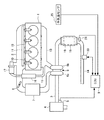
図1は、本発明にかかる内燃機関を車両駆動用ディーゼルエンジンに適用した態様である。図1において、エンジン1は、直列4気筒ディーゼルエンジンであり、各気筒の燃焼室には、吸気マニホールド2および吸気管3を介して吸気が導入される。吸気管3の始端には、エアクリーナ4が設けられ、吸気管3には、エアフロメータ(AFM)5、ターボチャージャ6のコンプレッサ6a、インタークーラ7、スロットルバルブ8が設けられている。本発明の実施の形態では、本発明にかかる内燃機関を車両駆動用ディーゼルエンジンに適用した態様について説明しているが、本発明にかかる内燃機関をガソリンエンジンに適用することも可能である。
FIG. 1 shows a mode in which an internal combustion engine according to the present invention is applied to a vehicle driving diesel engine. In FIG. 1, an engine 1 is an in-line four-cylinder diesel engine, and intake air is introduced into a combustion chamber of each cylinder via an
エアフロメータ5は、エアクリーナ4を介して吸気管3に流入する新気の空気量に応じた出力信号をエンジンコントロール用電子制御ユニット(ECU)9に出力し、ECU9はエアフロメータ5の出力信号に基づいて吸入空気量を演算するようになっている。
The air flow meter 5 outputs an output signal corresponding to the amount of fresh air flowing into the intake pipe 3 via the
また、エンジン1の各気筒の燃焼室には、それぞれ燃料噴射弁10から燃料が噴射される。各燃料噴射弁10は、コモンレール11に接続されており、コモンレール11には、図示しない燃料ポンプから燃料が供給される。各燃料噴射弁10の開弁時期、開弁期間、および燃料噴射量は、エンジン1の運転状態に応じてECU9によって制御されている。
Further, fuel is injected from the
また、エンジン1の各気筒の燃焼室で生じた排気ガスは、排気マニホールド13を介して排気管14に排出され、図示しないマフラーを介して大気に排出される。排気マニホールド13に排出された排気ガスの一部は、排気還流管15を介して吸気マニホールド2に再循環可能になっており、排気還流管15の途中にはEGRクーラ16とEGR弁17が設けられている。EGR弁17は、エンジン1の運転状態に応じてECU9によって開度制御され、排気還流量を制御するようになっている。
Further, the exhaust gas generated in the combustion chamber of each cylinder of the engine 1 is discharged to the
排気管14の途中には、ターボチャージャ6のタービン6b、DPF(Diesel Particulate Filter)18を収容したケーシング19、および排気ガスセンサ20が設けられている。タービン6bは、排気ガスによって駆動され、タービン6bに連結されたコンプレッサ6aを駆動して吸気を昇圧する。DPF18は、排気ガス中の粒子状物質(煤等)を捕集するフィルタエレメントに吸蔵還元型NOx触媒を坦持して構成されており、排気ガス中の粒子状物質を捕集すると共に、排気ガス中のHC、CO、NOxを浄化するものである。排気ガスセンサ20は、エンジン1の運転状態に応じてECU9によって制御される。本発明の実施の形態では、排気ガスセンサ20を酸素センサとして説明しているが、本発明にかかる排気ガスセンサが酸素センサに限定されないことはいうまでもない。
In the middle of the
なお、エンジン1から排気ガスセンサ20までの距離が長い排気管14やエンジン1と排気ガスセンサ20との間に触媒などの部材をもつ排気管14であると、排気ガスが排気ガスセンサ20に到達するまでに排気ガスの温度が低くなってしまい、排気ガスセンサ20の上流側に凝縮水が溜ったり、エンジン1から流出する排気ガスを受けた排気ガスセンサ20に水滴が付着しやすくなるため、ECU9は、後述する排気ガスセンサ20の加熱制御に関わる処理を行うようになっている。
Note that when the
排気ガスセンサ20は、センサ素子をヒータ35によって加熱して活性化し、その活性した状態のセンサ素子によって排気管14を流れる排気ガス中の酸素濃度を検出するようになっている。排気ガスセンサ20は、ジルコニア等のセラミックのセンサ素子からなり、センサ素子が活性状態(活性温度)のときに酸素の検出が可能である。そのため、排気ガスセンサ20は、素子温度を数100℃の活性温度まで上昇させると共にその活性温度を維持するために、センサ素子をヒータ35によって加熱している。また、排気ガスセンサ20は、保護カバーによってセンサ素子のセンシング部分が覆われており、その保護カバーに設けられた小孔から排気ガスを導入している。
The
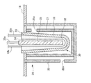
図2も参照して、排気ガスセンサ20について説明する。図2は、本発明の第1の実施の形態に係る排気ガスセンサ20の断面図である。排気ガスセンサ20は、センサ本体30を有しており、センサ本体30の外側に内側保護カバー21を配備し、さらに内側保護カバー21の外側に外側保護カバー22を配備している。内側保護カバー21の側面には、排気ガスを導入するための小さいガス孔21aが複数個設けられており、外側保護カバー22の側面にも、ガス孔21aとはセンサ本体30を挟んで反対側の位置に、排気ガスを導入するための小さいガス孔22aが複数個設けられている。
The
内側保護カバー21および外側保護カバー22は、センサ本体30が排気ガスと直接接触することを防止し、センサ本体30に対する保温性を確保すると共に、センサ本体30が排気管14内に溜まった凝縮水を直接被水するのを防止するためのものである。
The inner
センサ本体30は、抵抗拡散層31、固体電界質層32(センサ素子)、外側電極層33、内側電極層34、およびヒータ35によって構成されている。
The
抵抗拡散層31は、抵抗拡散層31の開口端部が排気管14の管壁の孔に嵌め込まれた状態で固定されており、抵抗拡散層31の内側には、固体電界質層32が配置されて固着されている。また、固体電界質層32は、外側電極層33と内側電極層34とで挟まれた状態で配置されて固着されている。外側電極層33の一端部には、電線33aが接続され、内側電極層34の一端部には、電線34aが接続されている。電線33aと電線34aとの間にはセンサ回路(図示せず)が接続され、センサ回路から外側電極層33と内側電極層34との間に電圧が印加される。
The
固体電界質層32が活性状態の場合、排気ガス中の酸素濃度に比例して外側電極層33と内側電極層34との間に流れる電流が変化する。外側電極層33と内側電極層34との間に流れる電流が検出され、電流値及び印加電圧値がECU9に送信される。
When the
ヒータ35は、固体電界質層32の素子温度を活性温度まで上昇させると共にその活性化した固体電界質層32の活性状態を維持するためのものであり、固体電界質層32の内側に形成される空間に配設される。ECU9からの制御信号に応じた電力が電線35aを介してヒータ35に供給されたとき、ヒータ35は、固体電界質層32を加熱するようになっている。
The
図1に示すように、排気管14においてケーシング19の直ぐ下流には、ケーシング19から流出する排気ガスの温度に対応した出力信号をECU9に出力する排気温度センサ24が設けられている。また、内燃機関の外気温に対応した出力信号をECU9に出力する外気温センサ25が設けられている。
As shown in FIG. 1, an
ECU9は、双方向バスによって相互に接続されたROM(リードオンリメモリ)、RAM(ランダムアクセスメモリ)、CPU(セントラルプロセッサユニット)、入力ポート、出力ポートを具備している。例えば、入力ポートには、エアフロメータ5で検出された信号、排気ガスセンサ20で検出された信号、および排気温度センサ24で検出された信号が入力され、出力ポートには、各燃料噴射弁10やEGR弁17を制御するための信号や排気ガスセンサ20のヒータ35を制御するための信号が出力される。
The
ECU9は、エンジン1の燃料噴射量制御等の基本制御を行うほか、センサ素子を活性化させるため、排気ガスセンサ20のヒータ35の通電状態を制御するようになっている。
The
ECU9は、後述するように、本発明に係る凝縮水量推定手段、凝縮水有無判定手段、および加熱制御手段を構成する。以下、本発明の実施の形態に係る内燃機関の制御装置を構成するECU9の特徴的な構成について、図面を参照して説明する。ECU9は、排気管14内の凝縮水量を推定するようになっている。従って、ECU9は、凝縮水量推定手段を構成している。また、ECU9は、推定した凝縮水の量の有無を判定するようになっている。従って、ECU9は、凝縮水有無判定手段を構成している。また、ECU9は、ヒータ35に対して通電を行うことで排気ガスセンサ20を加熱するよう制御する。従って、ECU9は、加熱制御手段を構成している。
As will be described later, the
また、排気温度センサ24は、本発明に係る排気温度検出手段を構成し、エアフロメータ5は、本発明に係るガス流量検出手段を構成し、外気温センサ25は、本発明に係る外気温検出手段を構成する。
The
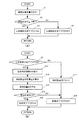
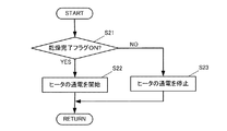
次に、動作について説明する。以下、本発明の第1の実施の形態に係る内燃機関の制御装置による排気ガスセンサ20の加熱制御に関わる処理について説明する。図3および図4は、本発明の第1の実施の形態に係る排気ガスセンサ20の加熱制御に関するフローチャートである。図3(a)は、排気管14内の凝縮水の有無判定に関するフローチャートである。図3(b)は、排気管14内の乾燥判定に関するフローチャートである。図4は、排気ガスセンサ20のヒータ35の通電状態の制御に関するフローチャートである。なお、本発明の第1の実施の形態では、排気ガスセンサ20の上流側に凝縮水が溜まった場合を想定して説明する。
Next, the operation will be described. Hereinafter, processing related to heating control of the
図3および図4に示した処理は、ECU9を構成するCPUによってエンジン1が始動してから所定の時間間隔で実行されると共に、CPUによって処理可能なプログラムで実現されるものである。ここで、所定の時間間隔とは、例えば数秒またはそれ以下の時間毎などの間隔を意味する。
The processing shown in FIGS. 3 and 4 is implemented by a program that can be processed by the CPU while being executed at predetermined time intervals after the engine 1 is started by the CPU constituting the
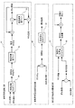
まず、図3(a)に示すように、ECU9は、エンジン1が始動すると排気管14内の凝縮水の推定を行い、凝縮水推定量を算出する(ステップS1)。ここで、排気管14内に溜まる凝縮水の量を推定するための凝縮水量推定処理について図5を参照しながら詳細に説明する。図5は、本発明の第1の実施の形態に係る凝縮水量推定処理を表す制御ブロック図である。
First, as shown in FIG. 3A, when the engine 1 is started, the
凝縮水量推定処理は、排気管壁温推定部91、排気管壁露点温度算出部92、排気管内凝縮水量推定部93によって構成されており、プログラムで実行される。また、凝縮水量推定処理では、供給熱量算出マップ94、壁温加算値マップ95、壁温減算値マップ96、露点温度算出マップ97、および凝縮水積算量算出マップ98が使用される。これらのマップは、ROMなどに予め記憶されている。
The condensed water amount estimation process includes an exhaust pipe wall
なお、本発明の第1の実施の形態では、壁温加算値マップ95、壁温減算値マップ96、凝縮水積算量算出マップ98は、排気ガスセンサ20の上流側に溜まった凝縮水を推定できるように設定されている。また、これらのマップは、排気ガスセンサ20の下流側に溜まった凝縮水を推定できるように設定可能であるが、本発明の第2の実施の形態で説明する。供給熱量算出マップ94および露点温度算出マップ97は、排気ガスセンサ20の上流側に溜まった凝縮水および排気ガスセンサ20の下流側に溜まった凝縮水を共通して推定できるものであるが上流側および下流側に対応して用意してもよい。また、これらのマップは、排気管14の形状などの状況に応じて設定されており、さらに排気ガスセンサ20の近傍が乾燥しているか否かが判定できるように設定されている。これらのマップに設定される値は、実験等で得られた値が用いられる。
In the first embodiment of the present invention, the wall temperature
排気管壁温推定部91は、供給熱量算出マップ94、壁温加算値マップ95、壁温減算値マップ96を使用して排気管の壁の温度を推定するようになっている。供給熱量算出マップ94は、入力値となるガス流量および排気温度と、出力値となる排気管供給熱量とを対応させたものである。壁温加算値マップ95は、入力値となる排気管供給熱量と、出力値となる壁温加算値とを対応させたものである。壁温減算値マップ96は、入力値となる推定壁温と外気温との差分と、出力値となる壁温減算値とを対応させたものである。
The exhaust pipe wall
例えば、供給熱量算出マップ94におけるガス流量および排気温度と排気管供給熱量との関係は、ガス流量が大きいほど排気管供給熱量も大きくなり、排気温度が大きいほど排気管供給熱量も大きくなるような傾向を有している。例えば、壁温加算値マップ95における排気管供給熱量と壁温加算値との関係は、排気管供給熱量が大きいほど壁温加算値も大きくなるような傾向を有している。例えば、壁温減算値マップ96における推定壁温から外気温の差分と壁温減算値との関係は、差分が大きいほど壁温減算値が大きくなるような傾向を有している。
For example, the relationship between the gas flow rate and the exhaust temperature and the exhaust pipe supply heat amount in the supply heat
排気管壁温推定部91の処理について次に説明する。ECU9は、供給熱量算出マップ94を参照して、エアフロメータ5から検出されたガス流量および排気温度センサ24から検出された排気温度と対応する排気管供給熱量を求める。ECU9は、壁温加算値マップ95を参照して、求まった排気管供給熱量と対応する壁温加算値を求める。
Next, the processing of the exhaust pipe wall
次に、ECU9は、壁温減算値マップ96を参照して、前回算出された推定壁温から外気温センサ25によって検出された外気温を減算した値と対応する壁温減算値を求める。ECU9は、壁温加算値マップ95を参照して求めた壁温加算値に前回算出された推定壁温を加算して加算値を求め、さらに壁温減算値マップ96を参照して求めた壁温減算値をこの加算値から減算した値を新たな推定壁温として更新する。なお、排気管壁温推定部91の処理が開始したときの推定壁温の初期値には、例えば、排気管壁温推定部91の処理が開始したときに外気温センサ25によって検出された外気温が設定される。
Next, the
排気管壁露点温度算出部92は、露点温度算出マップ97を使用して排気管14の壁の露点温度を算出するようになっている。露点温度算出マップ97は、入力値となる空燃比と、出力値となる露点温度とを対応させたものである。例えば、露点温度算出マップ97における空燃比と露点温度との関係は、空燃比が大きいほど露点温度が小さくなるような傾向を有している。
The exhaust pipe wall dew point
排気管壁露点温度算出部92の処理について次に説明する。まず、ECU9は、エアフロメータ5から検出されたガス流量と、燃料噴射弁10を介して現在噴射している燃料噴射の重量との比から空燃比を算出する。なお、空燃比は、排気ガスセンサ20からの出力結果でも求められるが、排気ガスセンサ20が活性化していない可能性があるため、ガス流量と燃料噴射の重量とを用いて空燃比が算出される。ECU9は、露点温度算出マップ97を参照して、算出した空燃比と対応する露点温度を求める。
Next, the processing of the exhaust pipe wall dew point
凝縮水量推定部93は、凝縮水積算量算出マップ98を使用して排気管14内の凝縮水量を推定するようになっている。凝縮水積算量算出マップ98は、入力値となるガス流量および相対壁温と、出力値となる凝縮水積算量とを対応させたものである。例えば、凝縮水積算量算出マップ98におけるガス流量および相対壁温と凝縮水積算量との関係は、ガス流量が大きいほど凝縮水積算量が小さくなり、相対壁温が大きいほど凝縮水積算量が小さくなるような傾向を有している。基本的には、ガス流量が基準量以上であると凝縮水積算量が負の値をとり、ガス流量が基準量以下であると凝縮水積算量が正の値をとるが、相対壁温に応じて基準量が変化したりする。
The condensed water
凝縮水量推定部93の処理について次に説明する。まず、ECU9は、排気管壁温推定部91によって推定された推定壁温と、排気管壁露点温度算出部92によって算出された露点温度との差である相対壁温を算出する。ECU9は、凝縮水積算量算出マップ98を参照して、算出した相対壁温およびエアフロメータ5から検出されたガス流量と対応する凝縮水積算量を求め、求まった凝縮水積算量に前回算出された凝縮水推定量を加算し、加算した値を新たな凝縮水推定量として更新する。なお、凝縮水積算量は、上述したように正または負の値をとり、凝縮水推定量が負の値になると0に設定される。なお、排気管壁露点温度算出部92の処理が開始したときの凝縮水推定量の初期値については後述する。
The process of the condensed water
ここで、図3(a)に示すように、ECU9は、ステップS1で算出された凝縮水推定量が0か否か、すなわち排気管14内の上流側の凝縮水推定量が無いか否かを判定する(ステップS2)。凝縮水推定量が無い場合、ECU9は、上流側排水完了フラグをONに設定し(ステップS3)、凝縮水推定量がある場合、上流側排水完了フラグをOFFに設定する(ステップS4)。なお、上流側排水完了フラグに設定された情報は、RAMなどに記憶される。
Here, as shown in FIG. 3A, the
また、ECU9は、排気管14内の乾燥判定処理を行うが、図3(b)に示すように、上流側排水完了フラグがONに設定されているか否かを判定する(ステップS11)。上流側排水完了フラグがONである場合、乾燥判定指数を算出する(ステップS12)。以下に、乾燥判定指数の算出処理について説明する。
Further, the
乾燥判定指数は、「排気管熱容量×外気温度補正係数」で求まる。排気管熱容量は、排気管14内の乾燥に必要な熱容量であり、排気管14の構造に対応した熱容量が予め決められている。また、入力値となる外気温と出力値となる外気温度補正係数とを対応させた外気温度補正係数マップがROMなどに予め記憶されており、ECU9は、外気温度補正係数マップを参照して、外気温センサ25から検出された外気温と対応する外気温度補正係数を求める。例えば、外気温度補正係数マップにおける外気温と外気温度補正係数との関係は、外気温が大きいほど外気温度補正係数が小さくなるような傾向を有している。
The dryness determination index is obtained by “exhaust pipe heat capacity × outside air temperature correction coefficient”. The exhaust pipe heat capacity is a heat capacity necessary for drying in the
次に、ECU9は、エンジン1から供給される排気管14の供給熱量に対する積算量を算出する(ステップS13)。詳細には、入力値となるガス流量および排気温度と、出力値となる積算量とを対応させた供給熱量積算量マップがROMなどに予め記憶されており、ECU9は、供給熱量積算量マップを参照して、エアフロメータ5から検出されたガス流量および排気温度センサ24から検出された排気温度と対応する積算量を求める。例えば、供給熱量積算量マップにおけるガス流量および排気温度と積算量との関係は、ガス流量が大きいほど積算量が大きく、排気温度も大きいほど積算量が大きくなるような傾向を有している。なお、積算量は、正負の値をとる。
Next, the
次に、ECU9は、ステップS12で算出された積算量を前回算出された供給熱量に積算し、積算した値を新たな供給熱量として更新する(ステップS14)。ここで、ECU9は、ステップS14で算出された供給熱量が、ステップS12で算出された乾燥判定指数よりも大きいか否かを判定する(ステップS15)。
Next, the
続いてECU9は、供給熱量が乾燥判定指数よりも大きい場合、乾燥したとみなして乾燥完了フラグをONに設定し(ステップS16)、供給熱量が乾燥判定指数以下である場合、乾燥完了フラグをOFFに設定する(ステップS18)。一方、ステップS11で上流側排水完了フラグがOFFである場合、ECU9は、供給熱量を0などに初期化し(ステップS17)、ステップS18で乾燥完了フラグをOFFに設定する。
Subsequently, if the supplied heat amount is larger than the drying determination index, the
また、図4に示すように、ECU9は、排気ガスセンサ20のヒータ35の通電処理を行うが、乾燥完了フラグがONに設定されているか否かを判定する(ステップS21)。乾燥完了フラグがONである場合、ECU9は、ヒータ35の通電を許可して開始すると共に排気ガスセンサ20を活性化させるように通電制御を行う(ステップS22)。また、ステップS22で、既にヒータ35に通電がなされていた場合、ECU9は、通電制御を継続する。一方、乾燥完了フラグがOFFである場合、ECU9は、ヒータ35の通電を停止する(ステップS23)。また、ステップS23で、既に通電が停止されていた場合、ECU9は、ヒータ35の通電を停止したままの状態とする。
Further, as shown in FIG. 4, the
以上説明したように、本発明の第1の実施の形態に係る車両の制御装置は、排気温度、ガス流量、および外気温を用いて排気管14内に溜まる凝縮水の量を推定し、推定された凝縮水の有無を判定することで、一般的に内燃機関に備えられているエアフロメータ5、排気温度センサ24、外気温センサ25からの出力値を使用し、凝縮水が無いと判定された場合にヒータを加熱するため、排気管14に溜まる凝縮水の量を計測する器具などを不要にして、排気ガスセンサ20の損傷防止にかかる製造コストを十分に低減することができる。また、本発明の第1の実施の形態に係る車両の制御装置は、排気管14に溜まる凝縮水の量を計測する器具などが不要になるため、省スペース化を図ることができる。
As described above, the vehicle control apparatus according to the first embodiment of the present invention estimates the amount of condensed water accumulated in the
ところで、排気ガスセンサ20が活性化した場合においても、エンジン1が長い間アイドリングしている場合など、排気ガスの温度が低くなってしまい、排気管14内に凝縮水が溜まったり、排気管14内が乾燥していない状態となったりすることがある。従って、図3(a)に示した排気管14内の凝縮水の有無判定、図3(b)に示した排気管14内の乾燥判定、および、図4に示した排気ガスセンサ20のヒータ35の通電における処理は、排気ガスセンサ20が活性化した場合においても、常時実施される。
By the way, even when the
ここで、エンジン1を停止させるためにイグニッションスイッチがOFFとなり、しばらくして再度イグニッションスイッチがONになった場合、排気管壁露点温度算出部92の処理が開始したときの凝縮水推定量の初期値には、例えば、直前のエンジン1が停止した時点の凝縮水推定量が設定される。また、ECU9に供給する電力が遮断される等の事象が発生した場合やエンジン1が長時間停止していた場合など、凝縮水推定量の初期値には、排気管14内に溜まることが可能な最大の凝縮水推定量が設定される。
Here, when the ignition switch is turned off to stop the engine 1 and the ignition switch is turned on again after a while, the initial amount of condensed water estimated when the processing of the exhaust pipe wall dew point
(第2の実施の形態)
本発明の第1の実施の形態では、排気ガスセンサ20の上流側に溜まった凝縮水を推定する形態としていたが、排気ガスセンサ20の下流側の排気管14の形状によっては排気ガスセンサ20の下流側に凝縮水が溜まる可能性もある。下流側に凝縮水が溜まった場合、車両が後進したときや車両の走行中に急ブレーキをかけたときなどに下流側の凝縮水が排気ガスセンサ20に被水してしまうため、本発明の第2の実施の形態では、上流側に溜まった凝縮水に加えて下流側に溜まった凝縮水を推定する形態とする。
(Second Embodiment)
In the first embodiment of the present invention, the condensed water accumulated on the upstream side of the
本発明の第2の実施の形態に係る車両の内燃機関は、本発明の第1の実施の形態に係る車両の内燃機関と同様の構成であるため、その説明を省略するが、本発明の第2の実施の形態に係る車両の内燃機関の構成については第1の実施の形態と同一の符号を用いて説明する。 The internal combustion engine of the vehicle according to the second embodiment of the present invention has the same configuration as the internal combustion engine of the vehicle according to the first embodiment of the present invention. The configuration of the internal combustion engine of the vehicle according to the second embodiment will be described using the same reference numerals as those in the first embodiment.
以下、本発明の第2の実施の形態に係る内燃機関の制御装置による排気ガスセンサ20の加熱制御に関わる処理について説明する。本発明の第2の実施の形態では、排気ガスセンサ20の上流側に溜まった凝縮水を推定すると共に乾燥判定を行い、加えて、排気ガスセンサ20の下流側に溜まった凝縮水を推定する形態をとる。
Hereinafter, processing related to heating control of the
図3は、排気ガスセンサ20の上流側に溜まった凝縮水の有無判定および排気管14内の乾燥判定に関するフローチャートである。図6は、排気ガスセンサ20の下流側に溜まった凝縮水の有無判定に関するフローチャートである。図7は、排気ガスセンサ20のヒータ35の通電状態の制御に関するフローチャートである。
FIG. 3 is a flowchart regarding the presence / absence determination of the condensed water accumulated on the upstream side of the
なお、図3、図6、および図7に示した処理は、ECU9を構成するCPUによって所定の時間間隔で実行されると共に、CPUによって処理可能なプログラムで実現されるものである。ここで、所定の時間間隔とは、例えば数秒またはそれ以下の時間毎などの間隔を意味する。
3, 6, and 7 are implemented by a program that can be processed by the CPU while being executed at predetermined time intervals by the CPU that constitutes the
まず、図3に示したように、排気ガスセンサ20の上流側に溜まった凝縮水の有無判定および排気管14内の乾燥判定に関するフローチャートの処理については、本発明の第1の実施の形態で既に説明したため、その説明を省略する。
First, as shown in FIG. 3, the processing of the flowchart regarding the presence / absence determination of the condensed water accumulated on the upstream side of the
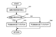
次に、図6に示すように、ECU9は、エンジン1の始動時またはエンジン1の始動後随時、排気管14内の凝縮水の推定を行い、凝縮水推定量を算出する(ステップS41)。ここで、排気管14内に溜まる凝縮水の量を推定するための凝縮水量推定処理については、図5で説明した凝縮水量推定処理と同様である。
Next, as shown in FIG. 6, the
ただし、図5で説明した壁温加算値マップ95、壁温減算値マップ96、凝縮水積算量算出マップ98は、排気ガスセンサ20の上流側に溜まった凝縮水を推定するためのものであったが、ステップS41では、壁温加算値マップ95に替えて下流側凝縮水推定用の壁温加算値マップ、壁温減算値マップ96に替えて下流側凝縮水推定用の壁温減算値マップ、凝縮水積算量算出マップ98に替えて下流側凝縮水推定用の凝縮水積算量算出マップが用いられる。これらのマップは、ROMなどに予め記憶されており、下流側凝縮水推定用のマップには、下流側の排気管14の形状などに適合した出力値が設定されている。
However, the wall temperature
ここで、図6に示すように、ECU9は、ステップS41で算出された凝縮水推定量が0か否か、すなわち排気管14内の下流側の凝縮水推定量が無いか否かを判定する(ステップS42)。凝縮水推定量が無い場合、ECU9は、下流側排水完了フラグをONに設定し(ステップS43)、凝縮水推定量がある場合、下流側排水完了フラグをOFFに設定する(ステップS44)。なお、下流側排水完了フラグに設定された情報は、RAMなどに記憶される。
Here, as shown in FIG. 6, the
なお、排気ガスは、排気ガスセンサ20の上流側から下流側に流れるため、乾燥判定処理は、排気ガスセンサ20の上流側についてのみ行う。
Since exhaust gas flows from the upstream side to the downstream side of the
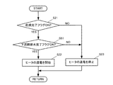
また、図7に示すように、ECU9は、排気ガスセンサ20のヒータ35の通電処理を行うが、乾燥完了フラグがONに設定されているか否かを判定し(ステップS21)、乾燥完了フラグがONである場合、下流側排水完了フラグがONに設定されているか否かを判定する(ステップS51)。
Further, as shown in FIG. 7, the
乾燥完了フラグおよび下流側排水完了フラグがONである場合、ECU9は、ヒータ35の通電を許可して開始すると共に排気ガスセンサ20を活性化させるように通電制御を行う(ステップS22)。また、ステップS22で、既にヒータ35に通電がなされていた場合、ECU9は、通電制御を継続する。
When the drying completion flag and the downstream drainage completion flag are ON, the
一方、乾燥完了フラグおよび下流側排水完了フラグの何れかがOFFである場合、ECU9は、ヒータ35の通電を停止する(ステップS23)。また、ステップS23で、既に通電が停止されていた場合、ECU9は、ヒータ35の通電を停止したままの状態とする。
On the other hand, when either the drying completion flag or the downstream drainage completion flag is OFF, the
以上説明したように、本発明の第2の実施の形態に係る車両の制御装置は、排気ガスセンサ20の上流側に溜まる排気管14内の凝縮水ならず、下流側に溜まる排気管14内の凝縮水の有無を判定するため、凝縮水の有無の判定精度を高めることができ、その上で排気ガスセンサ20のヒータ35を加熱するため、排気ガスセンサ20が損傷してしまうことを確実に防止することができる。
As described above, the vehicle control apparatus according to the second embodiment of the present invention is not limited to the condensed water in the
以上説明したように、本発明の実施の形態に係る車両の制御装置は、排気温度、ガス流量、および外気温を用いて排気管内に溜まる凝縮水の量を推定し、推定された凝縮水の有無を判定するため、一般的にエンジンに備えられている排気温度センサ24、エアフロメータ5、外気温センサ25からの出力値を使用し、凝縮水が無いと判定された場合にヒータを加熱するため、排気管14に溜まる凝縮水の量を計測する器具などを不要にして、排気ガスセンサ24の損傷防止にかかる製造コストを十分に低減することができ、ヒータ35の加熱制御を行う車両の制御装置全般に有用である。
As described above, the vehicle control apparatus according to the embodiment of the present invention estimates the amount of condensed water accumulated in the exhaust pipe using the exhaust temperature, the gas flow rate, and the outside air temperature, and estimates the condensed water. In order to determine the presence or absence, output values from the
1 エンジン(内燃機関)
2 吸気マニホールド
3 吸気管
4 エアクリーナ
5 エアフロメータ(ガス流量検出手段)
6 ターボチャージャ
6a コンプレッサ
6b タービン
7 インタークーラ
8 スロットルバルブ
9 ECU(凝縮水量推定手段、凝縮水有無判定手段、乾燥判定手段、加熱制御手段)
10 燃料噴射弁
11 コモンレール
13 排気マニホールド
14 排気管
15 排気還流管
16 EGRクーラ
17 EGR弁
18 DPF
19 ケーシング
20 排気ガスセンサ
21 内側保護カバー
22 外側保護カバー
24 排気温度センサ(排気温度検出手段)
25 外気温センサ(外気温検出手段)
26 内側保護カバー
30 センサ本体
31 抵抗拡散層
32 固体電界質層
33 外側電極層
34 内側電極層
35 ヒータ
1 engine (internal combustion engine)
2 Intake manifold 3
10
19
25 Outside air temperature sensor (outside air temperature detection means)
26 inner
Claims (3)
前記排気管の排気ガスの排気温度を検出する排気温度検出手段と、
前記内燃機関に吸気されるガスの流量を検出するガス流量検出手段と、
外気温を検出する外気温検出手段と、
前記内燃機関が始動したとき前記排気温度検出手段によって検出された排気温度、前記ガス流量検出手段によって検出されたガスの流量、および前記外気温検出手段によって検出された外気温を用いて前記排気管内に溜まる凝縮水の量を推定する凝縮水量推定手段と、
前記凝縮水量推定手段によって推定された凝縮水の有無を判定する凝縮水有無判定手段と、
前記凝縮水有無判定手段によって凝縮水が無いと判定された場合に前記ヒータの通電を許可するよう制御する加熱制御手段と、
を備えたことを特徴とする排気ガスセンサの制御装置。 In an exhaust gas sensor control device for controlling the energization state of a heater for heating an exhaust gas sensor provided in an exhaust pipe of an internal combustion engine,
Exhaust temperature detecting means for detecting the exhaust temperature of the exhaust gas in the exhaust pipe;
Gas flow rate detecting means for detecting a flow rate of gas sucked into the internal combustion engine;
An outside air temperature detecting means for detecting the outside air temperature;
Using the exhaust temperature detected by the exhaust temperature detection means when the internal combustion engine is started, the flow rate of gas detected by the gas flow rate detection means, and the outside air temperature detected by the outside air temperature detection means, the inside of the exhaust pipe Means for estimating the amount of condensed water accumulated in the
Condensed water presence / absence determining means for determining presence / absence of condensed water estimated by the condensed water amount estimating means;
A heating control means for controlling to allow energization of the heater when it is determined by the condensed water presence / absence determining means that there is no condensed water;
An exhaust gas sensor control apparatus comprising:
Priority Applications (5)
| Application Number | Priority Date | Filing Date | Title |
|---|---|---|---|
| JP2008075675A JP4618312B2 (en) | 2008-03-24 | 2008-03-24 | Exhaust gas sensor control device |
| US12/808,571 US8479494B2 (en) | 2008-03-13 | 2009-03-12 | Exhaust gas sensor control system and control method |
| AT09719611T ATE555295T1 (en) | 2008-03-13 | 2009-03-12 | CONTROL SYSTEM AND CONTROL METHOD FOR AN EXHAUST GAS SENSOR |
| EP09719611A EP2252785B1 (en) | 2008-03-13 | 2009-03-12 | Exhaust gas sensor control system and control method |
| PCT/IB2009/005060 WO2009112947A2 (en) | 2008-03-13 | 2009-03-12 | Exhaust gas sensor control system and control method |
Applications Claiming Priority (1)
| Application Number | Priority Date | Filing Date | Title |
|---|---|---|---|
| JP2008075675A JP4618312B2 (en) | 2008-03-24 | 2008-03-24 | Exhaust gas sensor control device |
Publications (2)
| Publication Number | Publication Date |
|---|---|
| JP2009228564A true JP2009228564A (en) | 2009-10-08 |
| JP4618312B2 JP4618312B2 (en) | 2011-01-26 |
Family
ID=41244239
Family Applications (1)
| Application Number | Title | Priority Date | Filing Date |
|---|---|---|---|
| JP2008075675A Active JP4618312B2 (en) | 2008-03-13 | 2008-03-24 | Exhaust gas sensor control device |
Country Status (1)
| Country | Link |
|---|---|
| JP (1) | JP4618312B2 (en) |
Cited By (8)
| Publication number | Priority date | Publication date | Assignee | Title |
|---|---|---|---|---|
| JP2012172535A (en) * | 2011-02-17 | 2012-09-10 | Hitachi Automotive Systems Ltd | Engine control device |
| JP2012237641A (en) * | 2011-05-11 | 2012-12-06 | Ngk Spark Plug Co Ltd | Fine particle detection system |
| JP2013163978A (en) * | 2012-02-09 | 2013-08-22 | Hitachi Automotive Systems Ltd | Control device of engine |
| JP2013234574A (en) * | 2012-05-07 | 2013-11-21 | Hitachi Automotive Systems Ltd | Internal combustion engine control device |
| KR101361351B1 (en) | 2013-01-22 | 2014-02-11 | 주식회사 현대케피코 | Method for controlling heater of oxygen sensor |
| JP2014100928A (en) * | 2012-11-16 | 2014-06-05 | Toyota Motor Corp | Hybrid car |
| US9097194B2 (en) | 2011-07-19 | 2015-08-04 | Hitachi Automotive Systems, Ltd. | Control device controlling sensor heating in internal combustion engine |
| WO2015141148A1 (en) * | 2014-03-17 | 2015-09-24 | 株式会社デンソー | Internal combustion engine control device |
Citations (5)
| Publication number | Priority date | Publication date | Assignee | Title |
|---|---|---|---|---|
| JP2004316594A (en) * | 2003-04-18 | 2004-11-11 | Toyota Motor Corp | Exhaust system control system for internal combustion engine |
| JP2004360563A (en) * | 2003-06-04 | 2004-12-24 | Toyota Motor Corp | Exhaust gas detector |
| JP2006220026A (en) * | 2005-02-09 | 2006-08-24 | Denso Corp | Control device for internal combustion engine |
| JP2007138832A (en) * | 2005-11-18 | 2007-06-07 | Denso Corp | Heater control device for gas sensor |
| JP2008014235A (en) * | 2006-07-06 | 2008-01-24 | Toyota Motor Corp | Exhaust sensor heater control device |
-
2008
- 2008-03-24 JP JP2008075675A patent/JP4618312B2/en active Active
Patent Citations (5)
| Publication number | Priority date | Publication date | Assignee | Title |
|---|---|---|---|---|
| JP2004316594A (en) * | 2003-04-18 | 2004-11-11 | Toyota Motor Corp | Exhaust system control system for internal combustion engine |
| JP2004360563A (en) * | 2003-06-04 | 2004-12-24 | Toyota Motor Corp | Exhaust gas detector |
| JP2006220026A (en) * | 2005-02-09 | 2006-08-24 | Denso Corp | Control device for internal combustion engine |
| JP2007138832A (en) * | 2005-11-18 | 2007-06-07 | Denso Corp | Heater control device for gas sensor |
| JP2008014235A (en) * | 2006-07-06 | 2008-01-24 | Toyota Motor Corp | Exhaust sensor heater control device |
Cited By (10)
| Publication number | Priority date | Publication date | Assignee | Title |
|---|---|---|---|---|
| JP2012172535A (en) * | 2011-02-17 | 2012-09-10 | Hitachi Automotive Systems Ltd | Engine control device |
| JP2012237641A (en) * | 2011-05-11 | 2012-12-06 | Ngk Spark Plug Co Ltd | Fine particle detection system |
| US9206757B2 (en) | 2011-05-11 | 2015-12-08 | Ngk Spark Plug Co., Ltd. | Particulate detection system |
| US9097194B2 (en) | 2011-07-19 | 2015-08-04 | Hitachi Automotive Systems, Ltd. | Control device controlling sensor heating in internal combustion engine |
| JP2013163978A (en) * | 2012-02-09 | 2013-08-22 | Hitachi Automotive Systems Ltd | Control device of engine |
| JP2013234574A (en) * | 2012-05-07 | 2013-11-21 | Hitachi Automotive Systems Ltd | Internal combustion engine control device |
| JP2014100928A (en) * | 2012-11-16 | 2014-06-05 | Toyota Motor Corp | Hybrid car |
| KR101361351B1 (en) | 2013-01-22 | 2014-02-11 | 주식회사 현대케피코 | Method for controlling heater of oxygen sensor |
| WO2015141148A1 (en) * | 2014-03-17 | 2015-09-24 | 株式会社デンソー | Internal combustion engine control device |
| JP2015175329A (en) * | 2014-03-17 | 2015-10-05 | 株式会社デンソー | Control device for internal combustion engine |
Also Published As
| Publication number | Publication date |
|---|---|
| JP4618312B2 (en) | 2011-01-26 |
Similar Documents
| Publication | Publication Date | Title |
|---|---|---|
| EP2252785B1 (en) | Exhaust gas sensor control system and control method | |
| US7526914B2 (en) | Heater control device for gas sensor | |
| JP4618312B2 (en) | Exhaust gas sensor control device | |
| US10513961B2 (en) | NOx offset diagnostic during engine soak | |
| US8136343B2 (en) | System for an engine having a particulate matter sensor | |
| JP5246284B2 (en) | Control device for internal combustion engine | |
| JP4240132B2 (en) | Control device for internal combustion engine | |
| JP4320744B2 (en) | Control device for internal combustion engine | |
| US7730718B2 (en) | Control system for internal combustion engine | |
| CN102667083A (en) | Exhaust purification system for internal combustion engines | |
| JP5110200B2 (en) | Internal combustion engine detection device | |
| JP4888426B2 (en) | Exhaust gas sensor control device | |
| US7931015B2 (en) | Method and apparatus for controlling diesel engine | |
| JP2010071257A (en) | Engine control device | |
| US11008918B2 (en) | Exhaust gas purification apparatus for an internal combustion engine | |
| JP5559960B2 (en) | NOx sensor and its degradation suppression recovery control device | |
| JP6505578B2 (en) | Filter failure detection device, particulate matter detection device | |
| US11053831B2 (en) | Exhaust gas purification apparatus for an internal combustion engine | |
| JP4780465B2 (en) | Oxygen sensor failure diagnosis device | |
| JP2008297932A (en) | Sensor information detecting device and exhaust temperature detecting device for internal combustion engine | |
| JP2008261757A (en) | Oxygen sensor failure diagnosis device | |
| JP2009191789A (en) | Catalyst degradation diagnosis device | |
| JP2008121573A (en) | Exhaust gas purification device for internal combustion engine |
Legal Events
| Date | Code | Title | Description |
|---|---|---|---|
| A977 | Report on retrieval |
Free format text: JAPANESE INTERMEDIATE CODE: A971007 Effective date: 20100225 |
|
| A131 | Notification of reasons for refusal |
Free format text: JAPANESE INTERMEDIATE CODE: A131 Effective date: 20100302 |
|
| A521 | Written amendment |
Free format text: JAPANESE INTERMEDIATE CODE: A523 Effective date: 20100430 |
|
| A131 | Notification of reasons for refusal |
Free format text: JAPANESE INTERMEDIATE CODE: A131 Effective date: 20100615 |
|
| A521 | Written amendment |
Free format text: JAPANESE INTERMEDIATE CODE: A523 Effective date: 20100806 |
|
| TRDD | Decision of grant or rejection written | ||
| A01 | Written decision to grant a patent or to grant a registration (utility model) |
Free format text: JAPANESE INTERMEDIATE CODE: A01 Effective date: 20100928 |
|
| A01 | Written decision to grant a patent or to grant a registration (utility model) |
Free format text: JAPANESE INTERMEDIATE CODE: A01 |
|
| A61 | First payment of annual fees (during grant procedure) |
Free format text: JAPANESE INTERMEDIATE CODE: A61 Effective date: 20101011 |
|
| FPAY | Renewal fee payment (event date is renewal date of database) |
Free format text: PAYMENT UNTIL: 20131105 Year of fee payment: 3 |
|
| R151 | Written notification of patent or utility model registration |
Ref document number: 4618312 Country of ref document: JP Free format text: JAPANESE INTERMEDIATE CODE: R151 |
|
| FPAY | Renewal fee payment (event date is renewal date of database) |
Free format text: PAYMENT UNTIL: 20131105 Year of fee payment: 3 |