JP2009228281A - Basement of building - Google Patents
Basement of building Download PDFInfo
- Publication number
- JP2009228281A JP2009228281A JP2008074232A JP2008074232A JP2009228281A JP 2009228281 A JP2009228281 A JP 2009228281A JP 2008074232 A JP2008074232 A JP 2008074232A JP 2008074232 A JP2008074232 A JP 2008074232A JP 2009228281 A JP2009228281 A JP 2009228281A
- Authority
- JP
- Japan
- Prior art keywords
- basement
- air
- gap
- hollow concrete
- concrete block
- Prior art date
- Legal status (The legal status is an assumption and is not a legal conclusion. Google has not performed a legal analysis and makes no representation as to the accuracy of the status listed.)
- Granted
Links
Images


Abstract
Description
本発明は、建物の地下室に係り、とくに結露を防止する構造に関する。 The present invention relates to a basement of a building, and more particularly to a structure that prevents condensation.
狭い敷地の有効利用を図るため、一般住宅に限らず、マンション(大型共同住宅)でも地下に倉庫室を設けることがある。大型の商業ビルディングのように、地下に除湿機能を持った空調設備を配している場合には、地下の結露の問題は生じないが、いわゆるエアコンをもたない換気扇だけの地下室は、湿気をもった空気の水分が冷気と混じり合って側壁や天井に結露となってあらわれる問題がある。 In order to effectively use a small site, not only ordinary houses but also apartments (large apartment houses) may have a warehouse room in the basement. If air conditioning equipment with a dehumidifying function is installed in the basement like a large commercial building, the problem of underground dew condensation does not occur, but the basement room with only a ventilation fan without an air conditioner has moisture. There is a problem that moisture in the air mixes with cold air and forms condensation on the side walls and ceiling.
このため、一般住宅に地下室を作っても結露によるカビの発生などで利用価値が失われたり、大型マンションのように地下に倉庫室を作っても結露によるカビの発生等によって倉庫室の利用価値が半減するなど、建築コストに見合う価値を発揮できない場合が少なくなかった。 For this reason, even if a basement is created in a general house, the utility value is lost due to the occurrence of mold due to condensation, or even if a warehouse room is constructed in the basement like a large apartment, the utility value of the warehouse room due to the occurrence of mold due to condensation, etc. In many cases, such as halving the value of the building, the value that is commensurate with the construction cost cannot be achieved.
結露の発生を確実に防止するには、除湿機能をもったエアコンディショナ装置を地下室に設けることが推奨される。しかしながら、結露を防止するためにエアコンディショナ装置を常時稼働させるのは経済的にも難しいことが多く、ショッピングセンターやデパートなど、大型の商業施設や美術館や駅などの公共施設を除けば、建物の地階部分の結露問題は、依然として解決されていないのが実情である。 In order to prevent the occurrence of condensation, it is recommended to install an air conditioner with a dehumidifying function in the basement. However, it is often economically difficult to operate the air conditioner device to prevent dew condensation at all times, except for large commercial facilities such as shopping centers and department stores, and public facilities such as museums and stations. The fact that the dew condensation problem in the basement is still not solved.
除湿機能をもったエアコンディショナ装置のように、設置コストとランニングコストがかかる装置ではなく、より低コストの装置で除湿を行う試みも提案されている。例えば、特許文献1のように、地下室の天井に熱交換素子を用いた空調装置を配する等である。
商業施設や公共施設以外の建物において、地下室の結露を防ぐために空調装置を用いた場合の問題は、設置コストが嵩み、メンテナンスコスト(維持経費)の負担が大きくかかる点にある。また外部の音が遮断された地下室では、空調装置の騒音も大きく聞こえて耳障りになる問題がある。 In buildings other than commercial facilities and public facilities, the problem of using an air conditioner to prevent dew condensation in the basement is that the installation cost increases and the burden of maintenance costs (maintenance costs) increases. Also, in the basement where the external sound is blocked, there is a problem that the noise of the air conditioner can be heard loudly and become annoying.
特許文献1のように、装置構成を単純化させた空調設備であっても、経年劣化に伴う故障やトラブルの可能性を否定できない。除湿のために常時駆動せざるを得ない空調装置は、騒音の点でも課題を残す。
Even if it is an air-conditioning installation which simplified the apparatus structure like
そこで、本発明の目的は、換気扇以外の空調設備を用いることなく、建物の地下室の結露を低コストで防止可能とする点にある。換気扇は、常時駆動する必要はなく、換気のためには必要である。常時駆動するわけではないから騒音の点では問題はない。 Therefore, an object of the present invention is to prevent condensation in a basement of a building at a low cost without using air conditioning equipment other than a ventilation fan. The ventilation fan does not need to be driven at all times, but is necessary for ventilation. There is no problem in terms of noise because it is not always driven.
前記目的を達成して、課題を解決するため、本発明に係る建物の地下室は、地下室の基礎床、側壁、天井をコンクリートによって成形するとともに、コンクリートの基礎床の上に空洞コンクリートブロックを敷設し、この空洞コンクリートブロックの上に断熱材を介して設けたコンクリート製の床を備え、前記空洞コンクリートブロックは、第一に、側壁に最も近い位置に配する空洞コンクリートブロックを地下室の側壁から離隔させて側壁との間に隙間を設け、第二に、隣接する空洞コンクリートブロック同士を離隔させて若干の隙間を設け、第三に、空洞コンクリートブロック同士の空洞が略直線的な空洞を作るように並べて配置してなる(請求項1)。 In order to achieve the above object and to solve the problems, the basement of the building according to the present invention is such that the basement floor, side walls, and ceiling of the basement are formed of concrete, and a hollow concrete block is laid on the concrete basement floor. And a concrete floor provided on the hollow concrete block via a heat insulating material. The hollow concrete block firstly separates the hollow concrete block located closest to the side wall from the side wall of the basement. So that there is a slight gap between the adjacent concrete blocks, and third, the cavities between the concrete blocks form a straight line. They are arranged side by side (Claim 1).
地下室の床面に、隙間を設けて空洞コンクリートブロックを配設すると、側壁と空洞コンクリートブロックの隙間、空洞コンクリートブロック同士の隙間、および略直線的に配した空洞コンクリートブロックの空洞が、地下室内の空気層の温度差に起因する対流空気の通り道となって、地下室内の空気を満遍なく循環させ、空気の滞留(淀み)に起因する結露を防止する。 When a hollow concrete block is arranged with a gap on the floor of the basement, the gap between the side wall and the hollow concrete block, the gap between the hollow concrete blocks, and the hollow of the hollow concrete block arranged in a substantially straight line are formed in the basement. It becomes a path of convection air due to the temperature difference of the air layer, and the air in the basement is circulated evenly to prevent condensation due to air retention (stagnation).
地下室の結露は、湿気をもった温かい空気が天井近くに滞留し、床面近傍に冷たい空気が滞留して、それらが空気層の境界付近で混じり合って生ずるケースが多い。このため、特許文献1でも天井付近の空気の除湿を行う構成をとる。
Condensation in the basement is often caused by warm, moist air staying near the ceiling and cold air staying near the floor, which are mixed near the boundary of the air layer. For this reason, also in
これに対して、地下室に空気の通り道を作って空気を自然流動させれば、空気層の滞りに起因する地下室の結露は確実に低減する。殆ど生じない。 On the other hand, if air is made to flow naturally in the basement by allowing air to flow naturally, the dew condensation in the basement due to the stagnation of the air layer is reliably reduced. It hardly occurs.
請求項2は、室内の側壁を装飾するパネルの設置に関する構造である。地下室の側壁および天井に配する化粧板(化粧パネル材)は、隣接する化粧板同士を離隔させて目地に若干の隙間を備えるよう設ける。 A second aspect of the present invention is a structure related to installation of a panel for decorating an indoor side wall. A decorative plate (decorative panel material) disposed on the side wall and ceiling of the basement is provided so that adjacent decorative plates are separated from each other and have a slight gap in the joint.
このようにしておけば、地下室内の空気は、化粧板の目地の隙間を通って自由に流動し、床に配した空洞コンクリートブロックを通過して冷気と暖気が均等に混合する状態を保つ。 If it does in this way, the air in a basement will flow freely through the crevice between the joints of a decorative board, and will pass the hollow concrete block arranged on the floor, and will maintain the state where cold air and warm air are mixed equally.
請求項3は、化粧板の目地を装飾する構造である。化粧板の目地に隙間を設けると、化粧板の背面にあるコンクリートが隙間を通して見えて、見栄えが悪い場合がある。そこで目地の隙間に化粧目地材を配するが、化粧板の目地と化粧目地材との間にも若干の隙間を設けて、空気の流動性を担保する。 The third aspect is a structure for decorating the joint of the decorative board. If a gap is provided in the joint of the decorative plate, the concrete on the back surface of the decorative plate can be seen through the gap and the appearance may be poor. Therefore, a makeup joint material is arranged in the joint gap, but a slight gap is also provided between the joint of the decorative plate and the joint joint material to ensure air fluidity.
本発明に係る建物の地下室によれば、冷気がある床面に空洞コンクリートブロックを隙間を設けて配したため、より多くの細い空気の通り道が出来、わずかな空気密度の変化でも空気の流動を生じさせる。空気は暖められると密度が低下するから、床の冷たい空気は上方にある密度の低い方向へ流れようとする一方、冷気が暖気側へ移動すると、隙間内の冷気の空気密度が低下して、今度は暖気が床の隙間内に流れようとする。 According to the basement of the building according to the present invention, since the hollow concrete block is provided with a gap on the floor where there is cold air, more narrow air passages can be made, and even a slight change in air density causes air flow. Let When the air is warmed, the density decreases, so the cold air on the floor tends to flow in the direction of low density above it, but when the cold air moves to the warm air side, the air density of the cold air in the gap decreases, This time, warm air tries to flow into the gaps in the floor.
床にある冷気側の通り道(隙間)は細いので、わずかでも空気が流動すれば当該部分の空気の流度は速く、空気密度は直ちに低下する。この空気密度の低下を埋めるために、室内の空気が隙間に流れ込む。 Since the passage (gap) on the cold side on the floor is narrow, if even a slight amount of air flows, the flow rate of air in that part is fast, and the air density decreases immediately. In order to compensate for this decrease in air density, indoor air flows into the gap.
地下室はいわば大きな箱であるが、このような空気密度の変化に伴う空気の流動は、通常の居室では起こりにくい。空気の密度変化が少ないため、暖気は上方に、冷気は下方にとどまって滞留する。 The basement is a so-called large box, but such a flow of air accompanying a change in air density is unlikely to occur in a normal living room. Since there is little change in the density of air, warm air stays upward and cool air stays downward.
しかし、空洞コンクリートブロックを床に多数の細い隙間を設けて敷き並べると、わずかな密度変化でも空気の流動が生じやすくなり、結果として、地下室の空気は常時ゆるやかに流動し、冷気と暖気の大量の混合による結露を生じさせない。 However, when hollow concrete blocks are laid out on the floor with many narrow gaps, air flow tends to occur even with slight changes in density, and as a result, the air in the basement constantly flows gently, resulting in a large amount of cold and warm air. Does not cause condensation due to mixing.
図1〜図4は、本発明に係る地下室の一実施形態を示すものである。図1に示すように、この実施形態に係る地下室1は、窓2の外に空間(いわゆるドライヤード)3をもったもので、基礎床4、側壁5、天井6の全体をコンクリートによって成形してある。7は地表面、Kは排水ポンプ等を設けるための空間(いわゆる釜場)である。一戸建て住宅やマンション等の躯体は、天井6の上に作る。符号Fは、換気口である。
1 to 4 show an embodiment of a basement according to the present invention. As shown in FIG. 1, a
この地下室1は、側壁5と天井6の内面に断熱材8を配する一方、基礎床4の上に空洞コンクリートブロック(建築用ブロック)10を敷設し、この空洞コンクリートブロック10の上に断熱材9を敷設して、その上にコンクリート製の床11を作る。床11は、コンクリートを打設して作っても良いし、成型品であるコンクリート板を敷設して作ってもよい。
In the
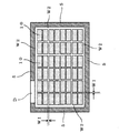
空洞コンクリートブロック10は、図2、図3に示すように、互いに細い隙間W1が出来るように並べるとともに、外周部に配する空洞コンクリートブロック10を側壁5からわずかに離隔させて隙間W2を設ける。図2において符号Dはドア開口である。隙間W1は10mm程度とすることが望ましい。隙間W2は地下室の大きさに応じて設定する。通常の場合、20〜100mmの範囲としておけば空気を流動させる隙間として機能する。
As shown in FIGS. 2 and 3, the
また、図4に示すように、空洞コンクリートブロック10は、隣接する空洞14が略一直線上に整列するよう配置する。空洞コンクリートブロック10が備える空洞14の数は、通常は2個または3個であるが、その数に関係なく、隣接するブロック(10)同士の各空洞14が途中で途切れることなく端から端まで貫通した状態を作るよう配設する。
Moreover, as shown in FIG. 4, the
地下室1には、内装のための内装ボード(化粧板)20を配することが望ましい。この内装ボード20は、例えば図4に示すように、側壁5の表面から若干離隔させて側壁5との間に隙間W3が出来るように配する。21は、内装ボード20を固定するための裏材である。また、内装ボード20は、互いに端部を密着させず、目地23に若干の隙間W4が出来るように配する。側壁5に限らず、天井6に配する内装ボード20も、目地(23)に隙間W4を設ける点は同じである。
It is desirable to arrange an interior board (decorative board) 20 for interior in the
側壁5に配する内装ボード20の最下端部は、例えば、外周にある空洞コンクリートブロック10の上面に配置することが望ましい。側壁5と内装ボード20との間の隙間W3の空気が、空洞コンクリートブロック10が作っている隙間W1および空洞14を自由に流れるようにするためである。
It is desirable that the lowermost end portion of the
目地23には、隙間W4を設けるので、好ましくは図5に示すように、見栄えを良好にするための化粧目地材25を設ける。この化粧目地材25は、例えば、内装ボード20の裏面に配するが、目地23の隙間を完全に密閉せず、目地23に沿って隙間W5を設けておく。側壁5と内装ボード20との間の隙間W3の空気を、居室の空気と自由に交換可能とするためである。Qは固定金具である。
Since the
かかる構成によれば、地下室1の居室の空気は、内装ボード20の目地23の隙間W4(W5)を介して、内装ボード20の裏面の隙間W3と交換可能であり、また内装ボード20の裏面の隙間W3の空気は、空洞コンクリートブロック10の空洞14および隙間W1を自由に流動できる状態にある。
According to this configuration, the air in the living room of the
結露が生じやすいのは、外気温が低い冬期である。冬期は、地下室1でもストーブ等の各種の暖房を使用する。このとき、暖房によって暖められた空気は居室の上方へ移動するが、この地下室1は、内装ボード20の目地に隙間W4、W5があるため、空気の対流により隙間W4、W5における空気の流動が生じる。温度差、つまり気圧差が生じているからである。
Condensation is likely to occur in winter when the outside temperature is low. During the winter, the
内装ボード20の裏面の隙間W3の気圧が微妙に変化すると、床に設けてある空洞コンクリートブロック10の空洞14および隙間W1の空気が微妙な圧力変化に応じて流動する。暖房を使用する冬期は、通常、内装ボード20の裏面の隙間W3の気圧が暖気の流入によって低下すると考えられるが、このような状態では、気圧が高い冷気(床の空気)が気圧の低い方向に流れて圧力を均衡させようとするからである。
When the air pressure in the gap W3 on the back surface of the
圧力差の基づく空気の流動は、室温と床の温度が逆転している場合も生じる。例えば、居住者が長期不在で、室温が外気の影響で低くなり、床の温度が地熱等の影響で高いとき、空気の圧力は床(空洞コンクリートブロック10の空洞14および隙間W1)が低くなり、居室側が高くなる。このときにも、内装ボード20の目地の隙間W4、W5を介して空気の流動が起こり、冷たい空気が床(下方)に流れて、床の空気が居室側に流れる。
The air flow based on the pressure difference also occurs when the room temperature and the bed temperature are reversed. For example, when the resident is absent for a long time, the room temperature is low due to the influence of outside air, and the temperature of the floor is high due to the influence of geothermal heat, etc., the pressure of the floor (the
このようにして、居室の温度状態に関係なく四季を通して空気が自由に動くため、地下室1は、空気の滞留に起因する結露、つまり淀んだ冷気/暖気の混合に起因する結露は生じにくい構造となる。
In this way, air freely moves through the four seasons regardless of the temperature state of the room, so that the
なお、本発明に係る地下室は、この実施形態に限定されない。例えば、地下室1の外部にドライエリアがない大型マンションやビルの地下室でも空気の流動を促して結露を防止できる作用効果は同じである。
The basement according to the present invention is not limited to this embodiment. For example, even in the basement of a large apartment or building where there is no dry area outside the
図4では、側壁5に配する最下端部の内装ボード20を、空洞コンクリートブロック10の上に配設するよう図示してあるが、これは本質的な条件ではない。例えば、図6に示すように、側壁5に配する最下端部の内装ボード20を、空洞コンクリートブロック10から外した位置(基礎床4の上など)に配設しても良いからである。但し、その場合は、内装ボード20の下端部に開口を設けて空気の流動を良好にする等、空気の流動を確保することが望ましい。
In FIG. 4, the lowermost end
内装ボード20は、地下室1の内装のために配するものであるが、内装ボード20を設けない場合でも、隙間W1、W2を設けて空洞コンクリートブロック10の空洞14を整列させれば、空気の自由な流動が生ずるため地下室1の結露を防止できる。
The
内装ボード20を設ける場合に、化粧目地材25は必ずしも必要ではない。見栄えを改善するためのものであり、空気の自由流動を促進させるものではないからである。化粧目地材25は内装ボードの表面側に設けても良いことは勿論である。
When the
1 地下室
2 窓
3 空間(いわゆるドライヤード)
4 基礎床
5 側壁
6 天井
7 地表面
8、9 断熱材
10 空洞コンクリートブロック
11 床
14 空洞
20 内装ボード(化粧板)
23 目地
25 化粧目地材
D ドア開口
K 空間(いわゆる釜場)
F 換気口
W1、W2、W3、W4、W5 隙間
1
23
F Ventilation port W1, W2, W3, W4, W5 Clearance
Claims (3)
コンクリートの基礎床の上に空洞コンクリートブロックを敷設し、
この空洞コンクリートブロックの上に断熱材を介して設けたコンクリート製の床を備え、
前記空洞コンクリートブロックは、
第一に、側壁に最も近い位置に配する空洞コンクリートブロックを地下室の側壁から離隔させて側壁との間に隙間を設け、
第二に、隣接する空洞コンクリートブロック同士を離隔させることにより若干の隙間を設け、
第三に、空洞コンクリートブロック同士の空洞が略直線的に並ぶよう配置することを特徴とする建物の地下室。 While molding the basement floor, side walls, and ceiling of the basement with concrete,
Laying a hollow concrete block on the concrete foundation floor,
A concrete floor provided on the hollow concrete block via a heat insulating material,
The hollow concrete block is
First, the hollow concrete block arranged at the position closest to the side wall is separated from the side wall of the basement to provide a gap between the side wall,
Second, a slight gap is provided by separating adjacent hollow concrete blocks,
Third, the basement of the building is characterized in that the cavities between the hollow concrete blocks are arranged in a substantially straight line.
隣接する化粧板同士を離隔させて目地に若干の隙間を備えることを特徴とする請求項1記載の建物の地下室。 With decorative panels on the side walls and ceiling of the basement,
The basement of a building according to claim 1, wherein the adjoining decorative plates are separated from each other and have a slight gap in the joint.
当該化粧目地材は、化粧板の目地の隙間との間に若干の隙間を備えることを特徴とする請求項2記載の建物の地下室。 It is equipped with a makeup joint material that makes up the joint gap between adjacent decorative plates from the back,
The basement of a building according to claim 2, wherein the decorative joint material includes a slight gap between the decorative joint material and the joint joint.
Priority Applications (1)
| Application Number | Priority Date | Filing Date | Title |
|---|---|---|---|
| JP2008074232A JP5118524B2 (en) | 2008-03-21 | 2008-03-21 | Basement of the building |
Applications Claiming Priority (1)
| Application Number | Priority Date | Filing Date | Title |
|---|---|---|---|
| JP2008074232A JP5118524B2 (en) | 2008-03-21 | 2008-03-21 | Basement of the building |
Publications (2)
| Publication Number | Publication Date |
|---|---|
| JP2009228281A true JP2009228281A (en) | 2009-10-08 |
| JP5118524B2 JP5118524B2 (en) | 2013-01-16 |
Family
ID=41243981
Family Applications (1)
| Application Number | Title | Priority Date | Filing Date |
|---|---|---|---|
| JP2008074232A Expired - Fee Related JP5118524B2 (en) | 2008-03-21 | 2008-03-21 | Basement of the building |
Country Status (1)
| Country | Link |
|---|---|
| JP (1) | JP5118524B2 (en) |
Cited By (1)
| Publication number | Priority date | Publication date | Assignee | Title |
|---|---|---|---|---|
| WO2011039964A1 (en) | 2009-09-30 | 2011-04-07 | パナソニック株式会社 | Photography device, photography method, and program |
Citations (6)
| Publication number | Priority date | Publication date | Assignee | Title |
|---|---|---|---|---|
| JPS5028102Y2 (en) * | 1972-07-19 | 1975-08-20 | ||
| JPS5873645A (en) * | 1981-10-26 | 1983-05-02 | 株式会社竹中工務店 | Construction of concrete slab |
| JPS6043926U (en) * | 1983-08-31 | 1985-03-28 | ナショナル住宅産業株式会社 | Air conditioning equipment that uses the subfloor surface |
| JPH02112736U (en) * | 1989-02-23 | 1990-09-10 | ||
| JPH0424385A (en) * | 1990-05-18 | 1992-01-28 | Fuji Seiko Honsha:Kk | Humidity conditioning wall surface panel |
| JP2005256440A (en) * | 2004-03-12 | 2005-09-22 | Daiken Trade & Ind Co Ltd | Humidity conditioning interior finish panel and mounting structure therefor |
-
2008
- 2008-03-21 JP JP2008074232A patent/JP5118524B2/en not_active Expired - Fee Related
Patent Citations (6)
| Publication number | Priority date | Publication date | Assignee | Title |
|---|---|---|---|---|
| JPS5028102Y2 (en) * | 1972-07-19 | 1975-08-20 | ||
| JPS5873645A (en) * | 1981-10-26 | 1983-05-02 | 株式会社竹中工務店 | Construction of concrete slab |
| JPS6043926U (en) * | 1983-08-31 | 1985-03-28 | ナショナル住宅産業株式会社 | Air conditioning equipment that uses the subfloor surface |
| JPH02112736U (en) * | 1989-02-23 | 1990-09-10 | ||
| JPH0424385A (en) * | 1990-05-18 | 1992-01-28 | Fuji Seiko Honsha:Kk | Humidity conditioning wall surface panel |
| JP2005256440A (en) * | 2004-03-12 | 2005-09-22 | Daiken Trade & Ind Co Ltd | Humidity conditioning interior finish panel and mounting structure therefor |
Cited By (1)
| Publication number | Priority date | Publication date | Assignee | Title |
|---|---|---|---|---|
| WO2011039964A1 (en) | 2009-09-30 | 2011-04-07 | パナソニック株式会社 | Photography device, photography method, and program |
Also Published As
| Publication number | Publication date |
|---|---|
| JP5118524B2 (en) | 2013-01-16 |
Similar Documents
| Publication | Publication Date | Title |
|---|---|---|
| KR101238125B1 (en) | Dual doors having ventilation function | |
| JP4595021B2 (en) | Air conditioning system and building | |
| KR101251221B1 (en) | Window ventilation system | |
| HU217496B (en) | Method and apparatus for the heating and cooling of buildings and heat insulating wall covering | |
| JP5118524B2 (en) | Basement of the building | |
| KR101078605B1 (en) | Cooling and heating system using radiation installation method thereof | |
| JP2007126913A (en) | Double window frame | |
| JP3187707B2 (en) | Building cooling / heating / ventilation system | |
| JP2005201601A (en) | Heating system for building | |
| JP5137599B2 (en) | Air conditioning system | |
| JP2008261535A (en) | Energy-saving constant-temperature ventilation system utilizing underground heat | |
| JP6403605B2 (en) | building | |
| KR200368316Y1 (en) | Door Frame for Preventing Dew Condensation | |
| JP4984118B2 (en) | Basement floor and double wall ventilation structure | |
| JP2004300709A (en) | Wall structure for building | |
| JP2015222004A (en) | Local heat insulation structure of building | |
| JP2010024809A (en) | Forced outer-wall air circulation type wood frame construction | |
| JP3368486B2 (en) | Architectural structures and buildings with them | |
| KR200201181Y1 (en) | Heating device of indoor | |
| KR102561367B1 (en) | Window System For Ventilation | |
| EP4350097A1 (en) | Dynamic insulation wall assembly and respective control method | |
| EP2823235B1 (en) | Ventilation arrangement | |
| JPH0351640A (en) | Ventilating device for housing | |
| JP2012167883A (en) | Heating/cooling system and building | |
| JP2008107053A (en) | Circulation type air conditioning method |
Legal Events
| Date | Code | Title | Description |
|---|---|---|---|
| A621 | Written request for application examination |
Free format text: JAPANESE INTERMEDIATE CODE: A621 Effective date: 20110303 |
|
| A977 | Report on retrieval |
Free format text: JAPANESE INTERMEDIATE CODE: A971007 Effective date: 20120523 |
|
| A131 | Notification of reasons for refusal |
Free format text: JAPANESE INTERMEDIATE CODE: A131 Effective date: 20120529 |
|
| A521 | Request for written amendment filed |
Free format text: JAPANESE INTERMEDIATE CODE: A523 Effective date: 20120730 |
|
| TRDD | Decision of grant or rejection written | ||
| A01 | Written decision to grant a patent or to grant a registration (utility model) |
Free format text: JAPANESE INTERMEDIATE CODE: A01 Effective date: 20121009 |
|
| A01 | Written decision to grant a patent or to grant a registration (utility model) |
Free format text: JAPANESE INTERMEDIATE CODE: A01 |
|
| A61 | First payment of annual fees (during grant procedure) |
Free format text: JAPANESE INTERMEDIATE CODE: A61 Effective date: 20121019 |
|
| R150 | Certificate of patent or registration of utility model |
Free format text: JAPANESE INTERMEDIATE CODE: R150 Ref document number: 5118524 Country of ref document: JP Free format text: JAPANESE INTERMEDIATE CODE: R150 |
|
| FPAY | Renewal fee payment (event date is renewal date of database) |
Free format text: PAYMENT UNTIL: 20151026 Year of fee payment: 3 |
|
| R250 | Receipt of annual fees |
Free format text: JAPANESE INTERMEDIATE CODE: R250 |
|
| R250 | Receipt of annual fees |
Free format text: JAPANESE INTERMEDIATE CODE: R250 |
|
| R250 | Receipt of annual fees |
Free format text: JAPANESE INTERMEDIATE CODE: R250 |
|
| R250 | Receipt of annual fees |
Free format text: JAPANESE INTERMEDIATE CODE: R250 |
|
| LAPS | Cancellation because of no payment of annual fees |